JP4956281B2 - Wireless communication apparatus and control method thereof - Google Patents
Wireless communication apparatus and control method thereof Download PDFInfo
- Publication number
- JP4956281B2 JP4956281B2 JP2007142323A JP2007142323A JP4956281B2 JP 4956281 B2 JP4956281 B2 JP 4956281B2 JP 2007142323 A JP2007142323 A JP 2007142323A JP 2007142323 A JP2007142323 A JP 2007142323A JP 4956281 B2 JP4956281 B2 JP 4956281B2
- Authority
- JP
- Japan
- Prior art keywords
- wireless communication
- communication device
- communication network
- network
- joiner
- Prior art date
- Legal status (The legal status is an assumption and is not a legal conclusion. Google has not performed a legal analysis and makes no representation as to the accuracy of the status listed.)
- Active
Links
Images


Classifications
-
- H—ELECTRICITY
- H04—ELECTRIC COMMUNICATION TECHNIQUE
- H04N—PICTORIAL COMMUNICATION, e.g. TELEVISION
- H04N1/00—Scanning, transmission or reproduction of documents or the like, e.g. facsimile transmission; Details thereof
- H04N1/00127—Connection or combination of a still picture apparatus with another apparatus, e.g. for storage, processing or transmission of still picture signals or of information associated with a still picture
- H04N1/00347—Connection or combination of a still picture apparatus with another apparatus, e.g. for storage, processing or transmission of still picture signals or of information associated with a still picture with another still picture apparatus, e.g. hybrid still picture apparatus
-
- H—ELECTRICITY
- H04—ELECTRIC COMMUNICATION TECHNIQUE
- H04N—PICTORIAL COMMUNICATION, e.g. TELEVISION
- H04N23/00—Cameras or camera modules comprising electronic image sensors; Control thereof
- H04N23/60—Control of cameras or camera modules
- H04N23/66—Remote control of cameras or camera parts, e.g. by remote control devices
- H04N23/661—Transmitting camera control signals through networks, e.g. control via the Internet
-
- H—ELECTRICITY
- H04—ELECTRIC COMMUNICATION TECHNIQUE
- H04W—WIRELESS COMMUNICATION NETWORKS
- H04W4/00—Services specially adapted for wireless communication networks; Facilities therefor
- H04W4/70—Services for machine-to-machine communication [M2M] or machine type communication [MTC]
-
- H—ELECTRICITY
- H04—ELECTRIC COMMUNICATION TECHNIQUE
- H04W—WIRELESS COMMUNICATION NETWORKS
- H04W84/00—Network topologies
- H04W84/02—Hierarchically pre-organised networks, e.g. paging networks, cellular networks, WLAN [Wireless Local Area Network] or WLL [Wireless Local Loop]
- H04W84/10—Small scale networks; Flat hierarchical networks
- H04W84/12—WLAN [Wireless Local Area Networks]
-
- H—ELECTRICITY
- H04—ELECTRIC COMMUNICATION TECHNIQUE
- H04W—WIRELESS COMMUNICATION NETWORKS
- H04W84/00—Network topologies
- H04W84/18—Self-organising networks, e.g. ad-hoc networks or sensor networks
-
- H—ELECTRICITY
- H04—ELECTRIC COMMUNICATION TECHNIQUE
- H04W—WIRELESS COMMUNICATION NETWORKS
- H04W84/00—Network topologies
- H04W84/18—Self-organising networks, e.g. ad-hoc networks or sensor networks
- H04W84/20—Master-slave selection or change arrangements
-
- H—ELECTRICITY
- H04—ELECTRIC COMMUNICATION TECHNIQUE
- H04N—PICTORIAL COMMUNICATION, e.g. TELEVISION
- H04N2101/00—Still video cameras
-
- H—ELECTRICITY
- H04—ELECTRIC COMMUNICATION TECHNIQUE
- H04N—PICTORIAL COMMUNICATION, e.g. TELEVISION
- H04N2201/00—Indexing scheme relating to scanning, transmission or reproduction of documents or the like, and to details thereof
- H04N2201/0008—Connection or combination of a still picture apparatus with another apparatus
- H04N2201/0034—Details of the connection, e.g. connector, interface
- H04N2201/0037—Topological details of the connection
- H04N2201/0039—Connection via a network
-
- H—ELECTRICITY
- H04—ELECTRIC COMMUNICATION TECHNIQUE
- H04N—PICTORIAL COMMUNICATION, e.g. TELEVISION
- H04N2201/00—Indexing scheme relating to scanning, transmission or reproduction of documents or the like, and to details thereof
- H04N2201/0008—Connection or combination of a still picture apparatus with another apparatus
- H04N2201/0034—Details of the connection, e.g. connector, interface
- H04N2201/0048—Type of connection
- H04N2201/0055—By radio
-
- H—ELECTRICITY
- H04—ELECTRIC COMMUNICATION TECHNIQUE
- H04N—PICTORIAL COMMUNICATION, e.g. TELEVISION
- H04N2201/00—Indexing scheme relating to scanning, transmission or reproduction of documents or the like, and to details thereof
- H04N2201/0077—Types of the still picture apparatus
- H04N2201/0084—Digital still camera
-
- H—ELECTRICITY
- H04—ELECTRIC COMMUNICATION TECHNIQUE
- H04W—WIRELESS COMMUNICATION NETWORKS
- H04W8/00—Network data management
- H04W8/005—Discovery of network devices, e.g. terminals
Description
本発明は、無線通信装置において無線通信ネットワークを構築する場合の、通信制御技術に関するものである。 The present invention relates to a communication control technique when a wireless communication network is constructed in a wireless communication apparatus.
近年、無線通信技術の発展に伴い、様々な電子機器に無線通信機能が搭載されるようになってきている。これにより、家電や携帯電話、プリンタ、時計、カメラ、コピー機といった身の回りの電子機器が無線通信ネットワークで結ばれ、お互い無線通信が可能になることによって、今までにない相乗効果を生みだし、利便性が高まることが期待される。 In recent years, with the development of wireless communication technology, various electronic devices are equipped with a wireless communication function. As a result, personal electronic devices such as home appliances, mobile phones, printers, watches, cameras, copiers, etc. are connected via a wireless communication network, enabling wireless communication with each other, creating an unprecedented synergistic effect and convenience. Is expected to increase.
例えば、近年無線LAN端末として機能する電子機器が登場してきている。この無線LAN端末として機能する電子機器により構成される無線通信ネットワークとしては、基地局とその無線セル内に存在する無線LAN端末とで構成されるインフラストラクチャモードと、無線LAN端末のみで構成されるアドホックモードとがある。 For example, electronic devices that function as wireless LAN terminals have recently appeared. The wireless communication network configured by the electronic device functioning as the wireless LAN terminal includes an infrastructure mode including a base station and a wireless LAN terminal existing in the wireless cell, and only a wireless LAN terminal. There is an ad hoc mode.
アドホックモードの場合、基地局を必要とせず、電子機器間で直接通信することが可能である。このため、無線LAN端末として機能する電子機器による無線通信ネットワークの構築に際して、今後、更に利用されるようになると考えられる(なお、アドホックモードによる無線通信ネットワークに関する提案としては、例えば、下記特許文献1乃至3参照)。
ここで、無線LANの規格としては、例えばIEEE802.11等があり、構築される無線通信ネットワークを識別するネットワーク識別子として、ESSIDとBSSIDが定義されている。通常、ESSIDはユーザによって設定される。 Here, as a wireless LAN standard, for example, IEEE802.11 or the like is available, and ESSID and BSSID are defined as network identifiers for identifying a wireless communication network to be constructed. Usually, the ESSID is set by the user.
同規格の場合、アドホックモードにおいては、最初に無線通信ネットワーク機能を構築した電子機器が無線通信ネットワークのBSSIDと呼ばれるネットワーク識別子を決定するよう動作する。以下、この動作を行う電子機器をクリエータと呼ぶ。 For this standard, in an ad hoc mode, first electronic device to construct a wireless communication network function operates to determine a network identifier called a BSSID of a wireless communications network. Hereinafter, an electronic device that performs this operation is referred to as a creator.
また、2台目以降の電子機器は、同一のESSIDのビーコンを探し、ビーコンに含まれるBSSIDを用いて当該無線通信ネットワークに参加するよう動作する。以下、この動作を行う電子機器をジョイナと呼ぶ。 The second and subsequent electronic devices operate to search for a beacon having the same ESSID and participate in the wireless communication network using the BSSID included in the beacon. Hereinafter, an electronic device that performs this operation is referred to as a joiner.
しかしながら、アドホックモードの場合、これらの電子機器が無線通信ネットワークを構築する手順及び無線通信ネットワークに参加する手順を適切にしなければ、無線通信機能の起動のタイミングによっては複数の電子機器がクリエータになることがありえる。このような場合、異なるBSSIDを持った複数の無線通信ネットワークが構築されてしまうこととなる。 However, in the case of the ad hoc mode, if the procedure for constructing the wireless communication network and the procedure for joining the wireless communication network are not appropriate, a plurality of electronic devices become creators depending on the start timing of the wireless communication function. It can happen. In such a case, a plurality of wireless communication networks having different BSSIDs will be constructed.
例えば従来の技術では、電子機器の無線通信機能を起動させた場合、当該電子機器では、まず周囲に存在する無線通信ネットワークの有無を問い合わせるためのスキャン処理を行う。そしてスキャン処理の結果、同一のESSIDをもつ無線通信ネットワークが存在する旨の応答メッセージが返ってきた場合には、当該電子機器は、すでに構築されている無線通信ネットワークに参加する。 For example, in the conventional technique, when the wireless communication function of an electronic device is activated, the electronic device first performs a scan process for inquiring about the presence or absence of a wireless communication network existing in the vicinity. If a response message indicating that there is a wireless communication network having the same ESSID is returned as a result of the scanning process, the electronic device participates in the already established wireless communication network.
一方、無線通信ネットワークが存在する旨の応答メッセージが返ってこなかった場合には、スキャン処理を行った電子機器自身が無線通信ネットワークのクリエータとなり、無線通信ネットワークを構築する。 On the other hand, when a response message indicating that a wireless communication network exists is not returned, the electronic device that has performed the scanning process itself becomes a creator of the wireless communication network, and constructs the wireless communication network.
しかし、複数の電子機器がそれぞれの無線通信機能を同時に起動させた場合、同じタイミングでスキャン処理を行うので、他の電子機器から無線通信ネットワークが存在する旨の応答メッセージが返ってこない。この場合、全ての電子機器が同一のESSIDをもつ他の電子機器の存在を確認できずに、各々が異なるBSSIDを持つ無線通信ネットワークを構築してしまう。 However, when a plurality of electronic devices activate their wireless communication functions at the same time, scanning processing is performed at the same timing, so that a response message indicating that a wireless communication network exists is not returned from another electronic device. In this case, all of the electronic devices cannot confirm the presence of other electronic devices having the same ESSID, and each establishes a wireless communication network having a different BSSID.
この結果、通信したい複数の電子機器が同じ無線通信ネットワークに参加することができずに、電子機器間で通信することができなくなってしまうといった問題が発生する。このような問題は、複数の電子機器間で通信を試みる場合、大きな障害となる。 As a result, there arises a problem that a plurality of electronic devices desired to communicate cannot participate in the same wireless communication network and cannot communicate with each other. Such a problem becomes a big obstacle when trying to communicate between a plurality of electronic devices.
本発明は上記課題に鑑みてなされたものであり、無線通信ネットワークを構築するにあたり、無線通信装置が備える無線通信機能の起動タイミングによらず、無線通信ネットワークが適切に構築できるようにすることを目的とする。 The present invention has been made in view of the above problems, when building a wireless communications network, regardless of the timing of starting the wireless communication functions of the wireless communication device, to make it a wireless communication network can be constructed appropriately Objective.
上記の目的を達成するために本発明に係る無線通信装置は以下のような構成を備える。即ち、
無線通信ネットワークのクリエータとして機能するか、他の無線通信装置が形成した無線通信ネットワークに参加するジョイナとして機能するかを切り替えることが可能な無線通信装置であって、
無線機能の起動に応じて前記クリエータとして起動する起動手段と、
前記クリエータとして機能している他の無線通信装置を探索するための探索要求を送信する送信手段と、
第1の他の無線通信装置からの、前記探索要求に対する応答を受信した場合に、該応答に、前記第1の他の無線通信装置が第2の他の無線通信装置との間で無線通信ネットワークを構築していることを示す情報が含まれているか否かを判別する判別手段と、
前記判別手段による判別結果に基づいて、前記クリエータとして機能するか、前記ジョイナとして機能するかを判定する判定手段と、
前記判定手段により前記ジョイナとして機能すると判定された場合に、前記起動されたクリエータとしての機能を終了し、前記ジョイナとしての機能を開始するよう制御し、前記判定手段により前記クリエータとして機能すると判定された場合に、該クリエータとしての機能を維持するよう制御する制御手段とを備える。
In order to achieve the above object, a wireless communication apparatus according to the present invention has the following configuration. That is,
A wireless communication device capable of switching between functioning as a creator of a wireless communication network or functioning as a joiner participating in a wireless communication network formed by another wireless communication device ,
Starting means for starting as the creator in response to the start of a wireless function ;
Transmitting means for transmitting a search request for searching for another wireless communication device functioning as the creator ;
When a response to the search request is received from the first other wireless communication device, the first other wireless communication device performs wireless communication with the second other wireless communication device in response to the response. A discriminating means for discriminating whether or not information indicating that a network is constructed is included ;
Determination means for determining whether to function as the creator or the joiner based on a determination result by the determination means;
When it is determined by the determination means that the function as the joiner is performed, the function as the activated creator is terminated and the function as the joiner is started, and the determination means is determined to function as the creator. Control means for controlling to maintain the function as the creator .
本発明によれば無線通信ネットワークを構築するにあたり、無線通信装置が備える無線通信機能の起動タイミングによらず、無線通信ネットワークが適切に構築できるようになる。 According to the present invention, when a wireless communication network is constructed, the wireless communication network can be appropriately constructed regardless of the activation timing of the wireless communication function provided in the wireless communication apparatus.
以下、図面を参照しながら各実施形態の詳細について説明する。なお、以下の各実施形態では、無線通信機能が撮像装置に搭載される場合について説明するが、無線通信機能が搭載される電子機器(無線通信装置)は撮像装置に限定されず、他の電子機器(無線通信装置)であってもよいことはいうまでもない。 Details of each embodiment will be described below with reference to the drawings. In each of the following embodiments, a case where a wireless communication function is mounted on an imaging device will be described. However, an electronic device (wireless communication device) on which a wireless communication function is mounted is not limited to the imaging device, and other electronic devices Needless to say, it may be a device (wireless communication device).
[第1の実施形態]
1.無線通信ネットワークの構成
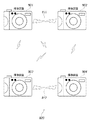
図1は本発明の第1の実施形態に係る無線通信機能を備える撮像装置により構築される無線通信ネットワーク100の構成を示す図である。本実施形態において、無線通信ネットワーク100は、撮像装置101と、撮像装置102と、撮像装置103とにより構築されるものとする。
[First Embodiment]
1. Configuration of Wireless Communication Network FIG. 1 is a diagram showing a configuration of a
なお、撮像装置101、撮像装置102、撮像装置103は、それぞれIEEE802.11規格に準拠する無線通信機能を備えており、各撮像装置101〜103は、アドホックモードのもと、無線通信により直接、無線接続されるものとする。これにより、各撮像装置101〜103は、それぞれ撮像された画像を他の撮像装置に送信したり、他の撮像装置において撮像された画像を受信したりすることができる。なお、本発明にかかる電子機器による無線LANの通信方式はこれに限定されず、それ以外の類似した通信方式であってもよい。
The
撮像装置101〜103が備える無線通信機能によれば、そのうちの2台の撮像装置間(無線通信装置間)において無線通信ネットワークが構築された場合、これを示すコードを残りの1台の撮像装置のスキャン処理に対する応答メッセージに含めて送信する。
According to the wireless communication function included in the
具体的には、残りの1台の撮像装置によるスキャン処理に対する応答メッセージである“Probe Response”(探索応答)の“Vender Specific Information Element”に、当該コードを入力する。なお、無線通信ネットワークが構築されたことを示す当該コードのことを、以下、「ネットワークコード」と呼ぶ。 Specifically, the code is input to “Vender Specific Information Element” of “Probe Response” ( search response ), which is a response message to the scan processing by the remaining one imaging device. The code indicating that the wireless communication network has been constructed is hereinafter referred to as “network code”.
2.撮像装置の構成
図2は本発明の第1の実施形態に係る無線通信機能を備える撮像装置101〜103の機能構成を示す図である。201は制御メモリ(ROM)、202は中央演算処理装置、203はメモリ(RAM)、204は無線通信部、205は入力部、206は表示部、207は撮像部、208は画像処理部、209はバスである。
2. Configuration of Imaging Device FIG. 2 is a diagram showing a functional configuration of the
本実施形態にかかる撮像装置は、撮像機能と無線通信機能とを備えており、これらの機能を実現するための制御プログラム(撮像制御部211、無線通信制御部212)やその制御プログラムで用いるデータ(不図示)は、制御メモリ201に記憶されている。
The imaging apparatus according to the present embodiment includes an imaging function and a wireless communication function, and control programs (
これらの制御プログラムやデータは、中央演算処理装置202の制御のもと、バス209を通じて適宜メモリ203に取り込まれ、中央演算処理装置202によって処理が実行される。
These control programs and data are appropriately fetched into the
これにより撮像部207や画像処理部208、無線通信部204等の各部が動作し、撮像機能と無線通信機能とが実現される。なお、撮像制御部211、無線通信制御部212による処理は、入力部205を介してユーザにより入力された指示を契機として開始され、その処理結果は表示部206に表示される。
Thereby, each unit such as the
3.無線通信ネットワーク100構築の際の処理の流れ
次に、撮像装置101〜103がそれぞれ備える無線通信機能により無線通信ネットワーク100を構築する場合の、各無線通信制御部212による処理の流れについて、図3〜図5を用いて説明する。
3. Flow of Processing when Building Wireless Communication Network 100 Next, the flow of processing performed by each wireless
図3は、撮像装置101〜103の各無線通信制御部212における処理の流れを示すシーケンス図であり、図4、図5は、シーケンス図(図3)に含まれるスキャン処理および判定処理の詳細を示すフローチャートである。ここで、撮像装置101〜103に設定されるESSIDは同一であるとする。
FIG. 3 is a sequence diagram showing a flow of processing in each of the wireless
図3に示すように、本実施形態では、まず撮像装置101と撮像装置102の無線通信制御部212が同時に起動される(ステップS311、S321)。
As shown in FIG. 3, in the present embodiment, first, the
撮像装置101及び撮像装置102では、無線通信制御部212を起動すると、自らが無線通信ネットワークのクリエータ(制御装置)となって、それぞれが無線通信ネットワークを構築するよう動作する(ステップS312、S322)。このように、無線通信制御部212を起動させると同時にスキャン処理をせずにクリエータとなって動作を開始することで、起動時の時間の短縮を図ることができる。
In the
次に、ステップS313では、撮像装置101の無線通信制御部212が、無線通信部204を介してスキャン処理を行い、撮像装置101の周囲(通信可能な範囲)に構築されている無線通信ネットワークの有無を判別し、判別結果を得る。
Next, in step S313, the wireless
図4は、スキャン処理の詳細な流れを示すフローチャートである。なお、図4に示すスキャン処理は、撮像装置101〜103により、それぞれステップS313、S323、S333にて共通して実行される処理であるが、ここでは、撮像装置101によるスキャン処理(ステップS313)の場合について説明する。
FIG. 4 is a flowchart showing a detailed flow of the scanning process. The scan process shown in FIG. 4 is a process that is commonly executed in steps S313, S323, and S333 by the
ステップS401では、Probe RequestランダムタイマT1をセットし、ステップS402においてT1のタイムアップを待つ。ステップS402において、T1のタイムアップが完了すると、ステップS403では、撮像装置101がProbe Request(探索要求)(301)を撮像装置102に送信する。
In step S401, a probe request random timer T1 is set, and in step S402, the time up for T1 is awaited. In step S402, when the time-up of T1 is completed, in step S403, the
ここで、撮像装置102は、すでにクリエータとして動作しているため、その存在を、Probe Response(302)を送信することにより、撮像装置101に報知する。
Here, since the
ステップS404では、Probe Request(301)に対する撮像装置102からのProbe Response(302)を受信したか否かを判定する。ステップS404において、Probe Response(302)を受信していないと判定された場合には、ステップS401に戻り、上記処理を繰り返す。
In step S404, it is determined whether or not a probe response (302) from the
一方、ステップS404において、Probe Response(302)を受信したと判定された場合には、スキャン処理(ステップS313)を終了する。 On the other hand, if it is determined in step S404 that the probe response (302) has been received, the scanning process (step S313) is terminated.
図3に戻る。スキャン処理(ステップS313)が終了すると、ステップS314では受信したProbe Response(302)に基づいて、判定処理を行う。 Returning to FIG. When the scanning process (step S313) is completed, a determination process is performed in step S314 based on the received probe response (302).
図5は、判定処理(ステップS314)の詳細な流れを示すフローチャートである。なお、図5に示す判定処理は、撮像装置101〜103により、それぞれステップS314、S324、S334にて共通して実行される処理であるが、ここでは、撮像装置101の判定処理(ステップS314)の場合について説明する。
FIG. 5 is a flowchart showing a detailed flow of the determination process (step S314). Note that the determination process illustrated in FIG. 5 is a process that is commonly executed in steps S314, S324, and S334 by the
ステップS501では、Probe Response(302)より、撮像装置102のBSSID、TimeStamp、Capability Informationを取得する。
In step S501, the BSSID, TimeStamp, and Capability Information of the
ステップS502では、受信したProbe Response(302)にネットワークコードが入力されているか否かを判定する。ステップS502においてネットワークコードが入力されていないと判定された場合には、無線通信ネットワークが構築されていないと判断し、ステップS503に進む。ステップS503では、撮像装置101がクリエータとして動作するかジョイナ(被制御装置)として動作するかを判定する。
In step S502, it is determined whether a network code is input to the received Probe Response (302). If it is determined in step S502 that a network code has not been input, it is determined that a wireless communication network has not been established, and the process proceeds to step S503. In step S503, it is determined whether the
ステップS503における判定は、例えば、BSSIDを条件に行うのであれば、撮像装置101のBSSIDと撮像装置102のBSSIDとを比較して、大きい方をクリエータ、小さい方をジョイナと判定する。言うまでもなく、この関係は逆であっても良い。
For example, if the determination in step S503 is performed on the basis of BSSID, the BSSID of the
なお、ステップS503における判定方法は、これに限られず、例えば、Probe Responseから得たBSSID以外の情報を用いて同様の比較を行い、クリエータとジョイナとを判定するようにしてもよい。 Note that the determination method in step S503 is not limited to this. For example, the creator and the joiner may be determined by performing the same comparison using information other than the BSSID obtained from the probe response.
一方、ステップS502においてネットワークコードが入力されていると判定された場合には、すでに無線通信ネットワークが構築されていると判断し、ステップS505に進み、クリエータ動作を停止する。 On the other hand, if it is determined in step S502 that a network code has been input, it is determined that a wireless communication network has already been established, and the process proceeds to step S505 to stop the creator operation.
なお、本実施形態の場合、この段階(ステップS314の段階)では2以上の撮像装置による無線通信ネットワークの構築がなされていない。このため、Vender Specific Information Elementにはネットワークコードが入力されておらず、撮像装置101がステップS502で“No”と判定され、ステップS505に進むことはない。
In the present embodiment, the wireless communication network is not constructed by two or more imaging devices at this stage (stage S314). For this reason, the network code is not input to the Vender Specific Information Element, and the
一方、ステップS504では、ステップS503における判定結果が、クリエータであった場合には、そのまま判定処理を終了する。一方、ステップS503における判定結果が、クリエータでなかった場合には、ステップS505に進み、クリエータ動作を停止する。更にステップS506において、ジョイナ動作を開始する(クリエータからジョイナに切り替える)。 On the other hand, in step S504, if the determination result in step S503 is creator, the determination process is terminated as it is. On the other hand, if the determination result in step S503 is not a creator, the process proceeds to step S505 to stop the creator operation. Further, in step S506, the joiner operation is started (switching from the creator to the joiner).
本実施形態では、撮像装置101がクリエータとして動作するため、ステップS504において“Yes”となり、そのまま判定処理を終了することとなる。
In this embodiment, since the
図3に戻る。ステップS314の判定処理が終了すると、ステップS315では、Vender Specific Information Elementにネットワークコードを入力する。 Returning to FIG. When the determination process in step S314 is completed, in step S315, the network code is input to the Vender Specific Information Element.
一方、撮像装置102では、無線通信制御部212が起動されクリエータとして動作を開始すると(ステップS321、S322)、ステップS323においてスキャン処理を行う。なお、スキャン処理(ステップS323)の詳細は、図4を用いてすでに説明済みであるため、ここでは説明は省略する。
On the other hand, in the
更に、ステップS324では、判定処理を行う。判定処理(ステップS324)の詳細も、図5を用いてすでに説明済みであるため、ここでは説明は省略する。ただし、撮像装置101による判定処理(ステップS314)と異なり、ステップS315の段階において、撮像装置101が、既にVender Specific Information Elementにネットワークコードを入力している。このため、ステップS501においてProbe Response(304)より抽出されるVender Specific Information Elementにはネットワークコードが入力されている。
In step S324, determination processing is performed. Since the details of the determination process (step S324) have already been described with reference to FIG. 5, the description thereof is omitted here. However, unlike the determination process (step S314) performed by the
したがって、撮像装置102の場合、図5のステップS502において、ネットワークコード有りと判定され、ステップS505において、クリエータ動作を停止し、ステップS506においてジョイナ動作を開始することとなる。
Therefore, in the case of the
図3に戻る。撮像装置101の判定処理(ステップS314)および撮像装置102の判定処理(ステップS324)が完了することにより、撮像装置101と撮像装置102との間に無線通信ネットワーク100’が構築される。
Returning to FIG. By completing the determination process (step S314) of the
更に、撮像装置102では、ステップS325において、Vender Specific Information Elementにネットワークコードを入力する。
Further, in step S325, the
続いて、撮像装置103の処理について説明する。撮像装置103の無線通信制御部212は、撮像装置101と撮像装置102との間の無線通信ネットワーク100’が構築された後、起動されるものとする(ステップS331)。
Subsequently, processing of the
撮像装置103についても、無線通信制御部212が起動された場合、自らが無線通信ネットワークのクリエータとなって、無線通信ネットワークを構築するよう動作する(ステップS332)。このように、無線通信制御部212を起動すると同時にスキャン処理をせずにクリエータとなって動作を開始することで、起動時の時間の短縮を図ることができる。
Also for the
次に、ステップS333において、撮像装置103の無線通信制御部212が、無線通信部204を介してスキャン処理を行い、撮像装置103の周囲に構築されている無線通信ネットワークの有無を調べる。なお、スキャン処理(ステップS333)の詳細は、図4を用いてすでに説明済みであるため、ここでは説明は省略する。
Next, in step S <b> 333, the wireless
更に、ステップS334では、判定処理を行う。判定処理(ステップS334)の詳細も、図5を用いてすでに説明済みであるため、ここでは説明は省略する。ただし、撮像装置101による判定処理(ステップS314)と異なり、ステップS315の段階において、撮像装置101が既にVender Specific Information Elementにネットワークコードを入力している。このため、ステップS501においてProbe Response(306)より抽出されるVender Specific Information Elementにはネットワークコードが入力されている。
In step S334, determination processing is performed. Details of the determination processing (step S334) have already been described with reference to FIG. However, unlike the determination process (step S314) performed by the
したがって、撮像装置103の場合、図4のステップS502において、ネットワークコード有りと判定され、ステップS505において、クリエータ動作を停止し、ステップS506においてジョイナ動作を開始することとなる。
Therefore, in the case of the
図3に戻る。撮像装置103の判定処理(ステップS334)が完了することにより、撮像装置101と撮像装置102と撮像装置103との間に無線通信ネットワーク100が構築される。つまり、撮像装置101と撮像装置102との間に構築された無線通信ネットワーク100’に、撮像装置103がジョイナとして参加することで、撮像装置101と撮像装置102と撮像装置103との間に無線通信ネットワーク100が構築されることとなる。
Returning to FIG. When the determination process (step S334) of the
更に、撮像装置103では、ステップS335において、Vender Specific Information Elementにネットワークコードを入力する。
Further, in step S <b> 335, the
なお、アドホックモードでは、既存の無線通信ネットワークに参加する場合、既存の電子機器に対し、無線通信ネットワークへの参加通知は無線LANのレイヤでは行わない。そのため、既存の電子機器では上位アプリケーションによって無線通信ネットワークへの参加通知情報をやり取りし、無線通信ネットワークに参加している電子機器を知ることになる。 In the ad hoc mode, when participating in an existing wireless communication network, notification of participation in the wireless communication network is not performed in the wireless LAN layer for existing electronic devices. For this reason, the existing electronic device exchanges participation notification information for the wireless communication network by a higher-level application to know the electronic devices participating in the wireless communication network.
また、自身が無線通信ネットワークを作った場合も、参加してきた電子機器の存在は無線LANのレイヤでは知りえないため、上位アプリケーションによって他の電子機器の存在を検知する。 In addition, even when the wireless communication network itself creates a wireless communication network, since the presence of the participating electronic device cannot be known at the wireless LAN layer, the presence of another electronic device is detected by a higher-level application.
以上の説明から明らかなように、本実施形態によれば、アドホックモードにおいて無線通信ネットワークを構築するにあたり、電子機器の無線通信機能が起動されると、それぞれがクリエータとして動作し、スキャン処理を実行する。これにより、クリエータとしての動作を維持するか、ジョイナとして動作するかの判定に必要な情報を電子機器が取得することが可能となる。この結果、電子機器の無線通信機能が同時に起動された場合でも、それぞれの電子機器が無線通信ネットワークを構築してしまうことがなく、一方がクリエータとして、他方がジョイナとして1つの無線通信ネットワークを構築することが可能となる。 As is clear from the above description, according to the present embodiment, when the wireless communication function of the electronic device is activated in constructing the wireless communication network in the ad hoc mode, each operates as a creator and executes the scanning process. To do. Thereby, it becomes possible for the electronic device to acquire information necessary for determining whether to maintain the operation as the creator or to operate as the joiner. As a result, even when the wireless communication function of the electronic device is activated at the same time, each electronic device does not build a wireless communication network, and one wireless communication network is constructed as one creator and the other as a joiner. It becomes possible to do.
また、本実施形態によれば、無線通信ネットワークを構築した電子機器は、以降、他の電子機器によるスキャン処理に対する応答メッセージにネットワークコードを含めて送信する。これにより、他の電子機器をジョイナとして動作させることが可能となる。 Further, according to the present embodiment, the electronic device that has constructed the wireless communication network subsequently transmits the response message for the scan processing by another electronic device including the network code. This makes it possible to operate other electronic devices as a joiner.
このように、本実施形態によれば、電子機器が備える無線通信機能の起動タイミングによらず、無線通信ネットワークが適切に構築できるようになる。 Thus, according to the present embodiment, a wireless communication network can be appropriately constructed regardless of the activation timing of the wireless communication function provided in the electronic device.
[第2の実施形態]
上記第1の実施形態では、2台の撮像装置101、102間で無線通信ネットワーク100’が構築されると、Vender Specific Information Elementにネットワークコードを入力することとした。これにより、無線通信ネットワーク100’が構築されたことを他の撮像装置(撮像装置103)に報知することが可能となった。
[Second Embodiment]
In the first embodiment, when the
この結果、無線通信ネットワーク100’が構築された後に複数の撮像装置の無線通信制御部が起動された場合でも、それらの撮像装置は既にある無線通信ネットワークに参加するよう動作することとなる。このため、複数の無線通信ネットワークが構築されてしまうといった事態を回避することが可能となる。
As a result, even when the wireless communication control units of a plurality of image capturing apparatuses are activated after the
しかし、仮に2台の撮像装置間で無線通信ネットワークが構築される前に他の撮像装置の無線通信制御部が起動されてしまった場合には、各撮像装置が行うスキャン処理に対して、複数の撮像装置がProbe Responseを送信して応答することとなる。この結果、無線通信ネットワークのクリエータ、ジョイナを決定するための条件が各撮像装置ごとに異なってしまい、適切に無線通信ネットワークが構築されないことが考えられる。 However, if the wireless communication control unit of another imaging device is activated before the wireless communication network is established between the two imaging devices, a plurality of scan processes performed by each imaging device are performed. The imaging device responds by transmitting a probe response. As a result, it is conceivable that the conditions for determining the creator and joiner of the wireless communication network differ for each imaging device, and the wireless communication network is not properly constructed.
そこで本実施形態では、2台の撮像装置間で無線通信ネットワークが構築される前に、他の撮像装置の無線通信制御部が起動された場合においても、適切に無線通信ネットワークが構築することが可能な無線通信機能を備える撮像装置について説明する。 Therefore, in this embodiment, even when the wireless communication control unit of another imaging device is activated before the wireless communication network is established between the two imaging devices, the wireless communication network can be appropriately constructed. An imaging device having a possible wireless communication function will be described.
なお、2台の撮像装置間において無線通信ネットワークが構築される前に、他の撮像装置の無線通信制御部を起動させた場合に問題となるのは、他の撮像装置がスキャン処理をした時に複数の撮像装置から応答メッセージが返信されることである。このように、複数のProbe Responseを受信した場合、撮像装置によってクリエータ、ジョイナを決定する条件が異なっていると、1つのクリエータを決定することができないからである。 Note that the problem arises when the wireless communication control unit of another imaging device is activated before the wireless communication network is established between the two imaging devices. A response message is returned from a plurality of imaging devices. As described above, when a plurality of Probe Responses are received, one creator cannot be determined if conditions for determining a creator and a joiner differ depending on the imaging device.
そこで、本実施形態では、撮像装置が複数のProbe Responseを受信した場合、当該撮像装置が、無線通信ネットワークからLeaveする構成とした。そして、無線通信ネットワークを構築中の撮像装置からのProbe Requestには応答せず、構築中の撮像装置間で無線通信ネットワークの構築が完了するまで待機することとした。以下、本実施形態の詳細について説明する。 Therefore, in the present embodiment, when the imaging apparatus receives a plurality of probe responses, the imaging apparatus is configured to leave from the wireless communication network. Then, it does not respond to the probe request from the imaging device that is constructing the wireless communication network, but waits until the construction of the wireless communication network is completed between the imaging devices that are being constructed. Details of this embodiment will be described below.
1.無線通信ネットワーク構築の際の処理の流れ
本実施形態における撮像装置101、撮像装置102、撮像装置103が無線通信ネットワークを構築する場合の処理の流れについて、図6と図7を用いて説明する。
1. Processing Flow when Building a Wireless Communication Network A processing flow when the
図6は、撮像装置101〜103の各無線通信制御部212における処理の流れを示すシーケンス図であり、図3は、シーケンス図(図6)に含まれるスキャン処理の詳細を示すフローチャートである。
FIG. 6 is a sequence diagram showing a flow of processing in each wireless
図6に示すシーケンス図において、撮像装置101及び撮像装置102において、無線通信ネットワークを構築するまでの処理の流れは、基本的に図3に示すシーケンス図に示した撮像装置101及び撮像装置102における処理の流れと同じである。
In the sequence diagram shown in FIG. 6, the flow of processing until the wireless communication network is constructed in the
一方、撮像装置103については、ステップS331において無線通信制御部212を起動し、ステップS332においてクリエータ動作を開始し、ステップS333において、スキャン処理を行うまでは、基本的に図3と同じである。
On the other hand, the
しかし、スキャン処理(ステップS333)において、Probe Request(307、309)を送信した時点で、撮像装置101、102間に無線通信ネットワーク100’は構築されていない。また、撮像装置101、102ともクリエータとして動作している。
However, when the probe request (307, 309) is transmitted in the scanning process (step S333), the wireless communication network 100 'is not established between the
このため、撮像装置103より送信されたProbe Request(307、309)に対して、撮像装置101、102では、それぞれProbe Response(308、310)を返信する。
For this reason, in response to the probe request (307, 309) transmitted from the
この結果、撮像装置103では、2つのProbe Response(308、310)を受信することとなる。
As a result, the
ステップS634では、スキャン処理(ステップS332)において2つのProbe Response(308、310)を受信した場合に対応した判定処理を実行する。 In step S634, a determination process corresponding to the case where two probe responses (308, 310) are received in the scan process (step S332) is executed.
図7は、判定処理(ステップS634)の詳細な流れを示すフローチャートである。なお、図7に示す判定処理は、撮像装置101〜103により、それぞれステップS614、S624、S634にて共通して実行される処理であるが、ここでは、特に撮像装置103の判定処理(ステップS634)の場合を中心に説明する。
FIG. 7 is a flowchart showing a detailed flow of the determination process (step S634). Note that the determination process illustrated in FIG. 7 is a process that is commonly executed by the
ステップS501では、Probe Response(308、310)より、撮像装置101、102のBSSID、TimeStamp、Capability Informationを取得する。
In step S501, the BSSID, TimeStamp, and Capability Information of the
ステップS502では、受信したProbe Response(308、310)にネットワークコードが入力されているか否かを判定する。ステップS502においてネットワークコードが入力されていないと判定された場合には、無線通信ネットワーク100’が構築されていないと判断し、ステップS707に進む。 In step S502, it is determined whether a network code is input to the received probe response (308, 310). If it is determined in step S502 that the network code has not been input, it is determined that the wireless communication network 100 'has not been established, and the process proceeds to step S707.
ステップS707では、撮像装置103に対してProbe Responseを送信した撮像装置が2台以上あるか否かを判定する。ステップS707において、2台以上ないと判定された場合には、ステップS503〜506の処理を行う。なお、これらの処理は図5において説明済みであるので、ここでは説明を省略する(撮像装置101、102による判定処理(ステップS614、S624)の場合には、これらの処理が実行されることとなる)。
In step S707, it is determined whether or not there are two or more imaging devices that have transmitted Probe Response to the
一方、ステップS707において、2台以上あると判定された場合には、ステップS708に進み、無線通信ネットワークからLeaveする。ステップS708において、無線通信ネットワークからLeaveすると、撮像装置103では、クリエータとして動作中であっても、他の撮像装置からのProbe Requestに対して応答せず、Probe Responseを送信しない。
On the other hand, if it is determined in step S707 that there are two or more units, the process proceeds to step S708 to leave the wireless communication network. In Step S708, when leaving from the wireless communication network, the
そして撮像装置103では、ステップS709において、他の撮像装置により無線通信ネットワークが構築されるまで待機すべく、待機タイマT2をセットする。更に、ステップS710では、待機タイマT2がカウントアップされるまで待機する。
In step S709, the
ステップS710において待機タイマT2がカウントアップされ、時間T2が経過したと判断されると、判定処理を終了する。 In step S710, when the standby timer T2 is counted up and it is determined that the time T2 has elapsed, the determination process ends.
一方、ステップS502において、ネットワークコードが入力されていると判定された場合には、無線通信ネットワークが構築されていると判断し、ステップS505に進む。ステップS505では、クリエータ動作を停止する。更にステップS506では、既に構築されている無線通信ネットワークに参加すべく、ジョイナ動作を開始する。 On the other hand, if it is determined in step S502 that a network code has been input, it is determined that a wireless communication network has been established, and the process proceeds to step S505. In step S505, the creator operation is stopped. In step S506, a joiner operation is started to join a wireless communication network that has already been established.
ここで、本実施形態では、図6に示すように、撮像装置103の無線通信制御部212が起動した時点で、撮像装置101と撮像装置102との間で無線通信ネットワーク100’が構築されておらず、それぞれクリエータとして動作している。
Here, in the present embodiment, as illustrated in FIG. 6, when the wireless
このため、撮像装置103がスキャン処理(ステップS333)を行うことで、撮像装置101、102よりそれぞれProbe Response(308、310)を受信する。また、このとき受信したProbe Response308、310には、Vender Specific Information Elementにネットワークコードが入力されていない。
For this reason, the
このため、ステップS502では、ネットワークコードなしと判定され、ステップS707では、2台以上あると判定され、ステップS708、S709、S710の各処理が実行される。 Therefore, in step S502, it is determined that there is no network code, and in step S707, it is determined that there are two or more units, and the processes of steps S708, S709, and S710 are executed.
ステップS710において、待機タイマT2のカウントアップが完了し、判定処理を終了すると、撮像装置103では、ステップS635に進み、再度、スキャン処理を実行する(再送信、再受信処理)。
In step S710, when the count-up of the standby timer T2 is completed and the determination process is completed, the
そして、Probe Request(305)が再度送信されると、クリエータとして動作する撮像装置101からは、Probe Response(306)が返信され、撮像装置103では、該応答を再度受信する。
Then, when the Probe Request (305) is transmitted again, the Probe Response (306) is returned from the
このとき、撮像装置101では、すでにステップS315においてネットワークコードの入力が完了しているため、返信されたProbe Response(306)には、ネットワークコードが入力されている。
At this time, in the
このため、ステップS636において判定処理が開始された場合、図7のステップS502において、ネットワークコード有りと判定され、すでに、無線通信ネットワーク100’が構築されていることを認識する。そこで、当該構築されている無線通信ネットワーク100’に参加すべく、ステップS505においてクリエータとしての動作を停止し、ステップS506においてジョイナとしての動作を開始する。 Therefore, when the determination process is started in step S636, it is determined in step S502 in FIG. 7 that there is a network code, and it is recognized that the wireless communication network 100 'has already been constructed. Therefore, in order to participate in the constructed wireless communication network 100 ', the operation as a creator is stopped in step S505, and the operation as a joiner is started in step S506.
この結果、撮像装置101〜103間において無線通信ネットワーク100が構築されることとなる。撮像装置103では、ジョイナとして動作を開始させた後は、ステップS335において、ネットワークコードを入力する。
As a result, the
以上の説明から明らかなように、本実施形態では、同時に3台の撮像装置が起動した場合でも、そのうちの2台の撮像装置により無線通信ネットワークが構築されるまで、残りの1台の撮像装置が待機する。この結果、適切に無線通信ネットワークを構築することが可能となる。 As is apparent from the above description, in the present embodiment, even when three image pickup devices are activated simultaneously, the remaining one image pickup device is used until the wireless communication network is constructed by the two image pickup devices. Waits. As a result, it is possible to construct a wireless communication network appropriately.
[第3の実施形態]
上記第1及び第2の実施形態では、撮像装置が3台の場合における無線通信ネットワークの構築について説明した。しかし、実際には3台以上の撮像装置が存在することが当然に想定される。また、撮像装置の位置・電波状態によっては、全ての撮像装置間において無線通信を実現させるに至らず、複数の撮像装置間でそれぞれ構築された無線通信ネットワークが複数存在してしまうことも考えられる。
[Third Embodiment]
In the first and second embodiments, the construction of the wireless communication network when there are three imaging devices has been described. However, it is naturally assumed that there are actually three or more imaging devices. In addition, depending on the position and radio wave state of the imaging device, wireless communication may not be realized between all the imaging devices, and there may be a plurality of wireless communication networks respectively constructed between a plurality of imaging devices. .
そこで本実施形態では、複数の撮像装置間で構築された無線通信ネットワークが複数存在した場合に、それらの無線通信ネットワークを一つにする方法について説明する。 Therefore, in the present embodiment, a method will be described in which when there are a plurality of wireless communication networks constructed between a plurality of imaging devices, the wireless communication networks are combined into one.
1.無線通信ネットワークの構成
図8は本発明の第3の実施形態に係る無線通信機能を備える撮像装置により構築される無線通信ネットワーク800の構成を示す図である。図8に示すように、無線通信ネットワーク800は、撮像装置801乃至804により構成されるものとする。
1. Configuration of Wireless Communication Network FIG. 8 is a diagram showing a configuration of a
なお、無線通信ネットワーク800を構築するにあたり、撮像装置801と撮像装置802とは、図3に示す処理が実行されることにより、既に無線通信ネットワーク811が構築されているものとする。同様に、撮像装置803と撮像装置804とは、図3に示す処理が実行されることにより、無線通信ネットワーク811とは異なる無線通信ネットワーク812が構築されているものとする。このように、撮像装置801〜804が、無線通信ネットワーク811と812とに2台ずつ分かれて無線通信ネットワークが構築されてしまった場合、全ての撮像装置間で通信を行うことはできない。そこで、以下の処理により、1つの無線通信ネットワーク800を構築することとする。
In constructing the
2.無線通信ネットワーク構築の際の処理の流れ
無線通信ネットワーク811と無線通信ネットワーク812を1つの無線通信ネットワーク800にするための処理の流れについて図9〜図11を用いて説明する。
2. Process Flow for Building Wireless Communication Network A process flow for making the
図9は、無線通信ネットワーク811と無線通信ネットワーク812とを1つの無線通信ネットワーク800にするための、撮像装置801〜804の各無線通信制御部212における処理の流れを示すシーケンス図である。また、図10、11は、シーケンス図(図9)に含まれる再スキャン処理、再判定処理の詳細を示すフローチャートである。
FIG. 9 is a sequence diagram showing a flow of processing in each wireless
無線通信ネットワーク811、812がそれぞれ構築された状態で、各撮像装置801乃至804は、それぞれ再スキャン処理(ステップS911、S921、S931、S941)を開始する。
In a state where the
図10は再スキャン処理(ステップS911、S921、S931、S941)の詳細な処理の流れを示すフローチャートである。なお、撮像装置801乃至804にて実行される再スキャン処理は同じであるため、ここでは、特に撮像装置801における再スキャン処理(ステップS911)について説明する。 FIG. 10 is a flowchart showing a detailed process flow of the rescan process (steps S911, S921, S931, and S941). Note that since the rescan processing executed by the imaging devices 801 to 804 is the same, here, the rescan processing (step S911) in the imaging device 801 will be particularly described.
ステップS1001において、撮像装置801は、Probe RequestランダムタイマT1をセットする。ステップS1002では、ランダムタイマT1がタイムアップするのを待つ。ステップS1002において、ランダムタイマT1がタイムアップすると、ステップS1003に進む。ステップS1003では、Probe Request(901)を送信する。 In step S1001, the imaging device 801 sets a Probe Request random timer T1. In step S1002, the process waits for the random timer T1 to expire. In step S1002, when the random timer T1 expires, the process proceeds to step S1003. In step S1003, a Probe Request (901) is transmitted.
撮像装置801がProbe Request(901)を送信すると、無線通信ネットワーク812に含まれる撮像装置803からProbe Response(902)が返信される。本実施形態では、無線通信ネットワーク812が構築された際に、撮像装置803がクリエータとして動作し、撮像装置804がジョイナとして動作したとする。このため、撮像装置803から、Probe Resoponse(902)が送信されることとなる。
When the imaging apparatus 801 transmits a probe request (901), a probe response (902) is returned from the
また、同じ無線通信ネットワーク811に含まれる他の撮像装置802からもProbe Response(904)が送信される。
Also, a probe response (904) is transmitted from another
ステップS1004では、Probe Responseを受信したか否かを判定する。ステップS1004において、Probe Responseが受信できなかったと判定された場合には、ステップS1001に戻り、上記処理を繰り返す。 In step S1004, it is determined whether or not a probe response has been received. If it is determined in step S1004 that the probe response has not been received, the process returns to step S1001 and the above process is repeated.
一方、ステップS1004において、Probe Responseが受信されたと判定された場合には、ステップS1005に進む。撮像装置801による再スキャン処理(ステップS911)では、Probe Response(902、904)を受信する。このため、ステップS1005において、撮像装置802、803のBSSID、TimeStamp、Capability Informationを取得する。
On the other hand, if it is determined in step S1004 that a Probe Response has been received, the process proceeds to step S1005. In the rescan process (step S911) by the imaging device 801, Probe Response (902, 904) is received. For this reason, in step S1005, BSSID, TimeStamp, and Capability Information of the
ステップS1006では、受信したProbe Response(902、904)にネットワークコードが入力されているか否かを判定する。ステップS1006においてネットワークコードが入力されていないと判定された場合には、他に無線通信ネットワークが構築されていないと判断し、ステップS1001に戻り、上記処理を繰り返す。一方、ステップS1006において無線通信ネットワークが構築されていると判断された場合には、再スキャン処理を終了する。 In step S1006, it is determined whether a network code is input to the received probe response (902, 904). If it is determined in step S1006 that no network code has been input, it is determined that no other wireless communication network has been established, and the process returns to step S1001 to repeat the above processing. On the other hand, if it is determined in step S1006 that a wireless communication network has been established, the rescan process is terminated.
撮像装置101が受信したProbe Response(902、904)には、いずれもネットワークコードが入力されているため、無線通信ネットワークが構築されていると判断し、再スキャン処理を終了する。
Since all the network responses are input to the probe responses (902, 904) received by the
図9に戻る。再スキャン処理(ステップS911)が完了すると、ステップS912に進み、受信したProbe Response(902、904)に基づいて再判定処理を実行する。 Returning to FIG. When the rescan process (step S911) is completed, the process proceeds to step S912, and the re-determination process is executed based on the received probe response (902, 904).
図11は、再判定処理の詳細な流れを示すフローチャートである。なお、ここでは、撮像装置801による再判定処理(ステップS912)について説明するが、撮像装置802乃至804による再判定処理(ステップS922、S932、S942)も同様の処理が実行される。
FIG. 11 is a flowchart showing a detailed flow of the redetermination process. Here, the re-determination process (step S912) by the imaging apparatus 801 will be described, but the same process is executed for the re-determination process (steps S922, S932, and S942) by the
ステップS1101では、受信したProbe Response(902、904)にそれぞれ入力されているネットワークコードが、撮像装置801に入力されたネットワークコードと同じネットワークコードであるか否かを判定する。 In step S1101, it is determined whether the network codes input to the received probe responses (902, 904) are the same network codes as the network codes input to the imaging device 801.
ここで、撮像装置802から送信されるProbe Response(904)には、撮像装置801に入力されたネットワークコードと同じネットワークコードが含まれる。一方、撮像装置803から送信されるProbe Response(902)には、撮像装置801に入力されたネットワークコードと異なるネットワークコードが含まれる。
Here, the probe response (904) transmitted from the
ステップS1101において、同じネットワークコードであると判定された場合には、撮像装置801が属する無線通信ネットワーク811と同じ無線通信ネットワークに属していると判断し、再判定処理を終了する。
If it is determined in step S1101 that they are the same network code, it is determined that they belong to the same wireless communication network as the
一方、ステップS1101において、同じネットワークコードでないと判定された場合には、撮像装置801が属する無線通信ネットワーク811とは異なる無線通信ネットワークが構築されていると判断し、ステップS1102に進む。
On the other hand, if it is determined in step S1101 that the network codes are not the same, it is determined that a wireless communication network different from the
ステップS1102では、無線通信ネットワーク811と無線通信ネットワーク812とを、どちらの無線通信ネットワークに統一させるかを判定する。
In step S1102, it is determined to which wireless communication network the
ステップS1102における判定方法としては、例えば、ネットワークコードに時間情報を付加しておき、その時間の早い方の無線通信ネットワークに統一する方法が挙げられる。 Examples of the determination method in step S1102 include a method of adding time information to a network code and unifying the wireless communication network with the earlier time.
または無線通信ネットワーク811のネットワークコードに撮像装置801と撮像装置802のMACアドレスの足したものを付加しておく。更に、無線通信ネットワーク812のネットワークコードに撮像装置803と撮像装置804のMACアドレスの足したものを付加しておく。そしてそれらのMACアドレスを足したものを比較して、大きい方の無線通信ネットワークに統一するという方法もある。なお、言うまでもなく、これらの関係は逆でも良い。
Alternatively, a network code of the
または、ネットワークコードが異なる無線通信ネットワークが構築されているということのみを認識し、Probe Responseに含まれる情報をもとに比較する方法でもよい。Probe Responseに含まれる情報としては、BSSID、Time Stamp、Beacon Interval、Capability Information等の情報が挙げられる。 Alternatively, a method of recognizing only that a wireless communication network with a different network code is constructed and comparing based on information included in the probe response may be used. Examples of information included in the probe response include information such as BSSID, Time Stamp, Beacon Interval, and Capability Information.
また、上記以外の情報を用いて同様に比較を行い、どちらの無線通信ネットワークに統一するかを決定するようにしてもよい。 Further, comparison may be similarly performed using information other than the above, and it may be determined which wireless communication network is unified.
ステップS1103では、撮像装置801が構築した無線通信ネットワーク811に統一するか否かを判定する。ステップS1103において、無線通信ネットワーク811に統一すると判定された場合には、再判定処理を終了する。
In step S1103, it is determined whether or not the
一方、ステップS1103において、無線通信ネットワーク811に統一すると判定されなかった場合には、ステップS1104に進み、クリエータの動作を停止し、ジョイナ動作を開始する。これにより、撮像装置801は、無線通信ネットワーク812に参加することとなる。ステップS1105では、入力したネットワークコードを、無線通信ネットワーク812に対応するネットワークコードに書き換える。
On the other hand, if it is determined in step S1103 that the
なお、本実施形態では、ステップS1102において、無線通信ネットワーク811に統一されるべきと判定されるものとする。このため、撮像装置801は、ステップS1103において、“Yes”と判断され、再判定処理を終了する。また、撮像装置802も同様に、ステップS1103において、“Yes”と判断され、再判定処理を終了する。
In this embodiment, it is determined in step S1102 that the
一方、撮像装置803、804の場合、再判定処理(ステップS932、S942)のステップS1103において、“No”と判断され、ステップS1104において、クリエータ動作を停止し、ジョイナ動作を開始する。更にステップS1105において、入力したネットワークコードを、無線通信ネットワーク811のネットワークコードに書き換える。
On the other hand, in the case of the
この結果、撮像装置803が無線通信ネットワーク811に参加し、無線通信ネットワーク800’が構築され、次に、撮像装置804が無線通信ネットワーク800’に参加し、無線通信ネットワーク800が構築される。
As a result, the
なお、撮像装置803が無線通信ネットワーク811に参加した時点で、無線通信ネットワーク812に属する他の撮像装置804に対して、その旨を通知することで、撮像装置804が無線通信ネットワーク800’に参加するように構成してもよい。
Note that when the
以上の説明から明らかなように、本実施形態によれば、複数の無線通信ネットワークが構築された場合でも、統一した無線通信ネットワークを再構築することが可能となる。 As is clear from the above description, according to the present embodiment, it is possible to reconstruct a unified wireless communication network even when a plurality of wireless communication networks are constructed.
[他の実施形態]
なお、本発明は、複数の機器(例えばホストコンピュータ、インタフェース機器、リーダ、プリンタなど)から構成されるシステムに適用しても、一つの機器からなる装置(例えば、複写機、ファクシミリ装置など)に適用してもよい。
[Other Embodiments]
Note that the present invention can be applied to a system (for example, a copier, a facsimile machine, etc.) consisting of a single device even when applied to a system composed of a plurality of devices (for example, a host computer, interface device, reader, printer, etc.). You may apply.
また、本発明の目的は、前述した実施形態の機能を実現するソフトウェアのプログラムコードを記録した記録媒体を、システムあるいは装置に供給するよう構成することによっても達成されることはいうまでもない。この場合、そのシステムあるいは装置のコンピュータ(またはCPUやMPU)が記録媒体に格納されたプログラムコードを読出し実行することにより、上記機能が実現されることとなる。なお、この場合、そのプログラムコードを記録した記録媒体は本発明を構成することになる。 Needless to say, the object of the present invention can also be achieved by supplying a system or apparatus with a recording medium that records a program code of software that implements the functions of the above-described embodiments. In this case, the function is realized by the computer (or CPU or MPU) of the system or apparatus reading and executing the program code stored in the recording medium. In this case, the recording medium on which the program code is recorded constitutes the present invention.
プログラムコードを供給するための記録媒体としては、例えば、フロッピ(登録商標)ディスク、ハードディスク、光ディスク、光磁気ディスク、CD−ROM、CD−R、磁気テープ、不揮発性のメモリカード、ROMなどを用いることができる。 As a recording medium for supplying the program code, for example, a floppy (registered trademark) disk, hard disk, optical disk, magneto-optical disk, CD-ROM, CD-R, magnetic tape, nonvolatile memory card, ROM, or the like is used. be able to.
また、コンピュータが読出したプログラムコードを実行することにより、前述した実施形態の機能が実現される場合に限られない。例えば、そのプログラムコードの指示に基づき、コンピュータ上で稼働しているOS(オペレーティングシステム)などが実際の処理の一部または全部を行い、その処理によって前述した実施形態の機能が実現される場合も含まれることは言うまでもない。 Further, the present invention is not limited to the case where the functions of the above-described embodiments are realized by executing the program code read by the computer. For example, an OS (operating system) running on a computer performs part or all of actual processing based on an instruction of the program code, and the functions of the above-described embodiments may be realized by the processing. Needless to say, it is included.
さらに、記録媒体から読出されたプログラムコードが、コンピュータに挿入された機能拡張ボードやコンピュータに接続された機能拡張ユニットに備わるメモリに書込まれた後、前述した実施形態の機能が実現される場合も含まれる。つまり、プログラムコードがメモリに書込まれた後、そのプログラムコードの指示に基づき、その機能拡張ボードや機能拡張ユニットに備わるCPUなどが実際の処理の一部または全部を行い、その処理によって実現される場合も含まれる。 Further, when the program code read from the recording medium is written in a memory provided in a function expansion board inserted into the computer or a function expansion unit connected to the computer, the functions of the above-described embodiments are realized. Is also included. That is, after the program code is written in the memory, the CPU or the like provided in the function expansion board or function expansion unit performs part or all of the actual processing based on the instruction of the program code, and is realized by the processing. This is also included.
Claims (19)
無線機能の起動に応じて前記クリエータとして起動する起動手段と、
前記クリエータとして機能している他の無線通信装置を探索するための探索要求を送信する送信手段と、
第1の他の無線通信装置からの、前記探索要求に対する応答を受信した場合に、該応答に、前記第1の他の無線通信装置が第2の他の無線通信装置との間で無線通信ネットワークを構築していることを示す情報が含まれているか否かを判別する判別手段と、
前記判別手段による判別結果に基づいて、前記クリエータとして機能するか、前記ジョイナとして機能するかを判定する判定手段と、
前記判定手段により前記ジョイナとして機能すると判定された場合に、前記起動されたクリエータとしての機能を終了し、前記ジョイナとしての機能を開始するよう制御し、前記判定手段により前記クリエータとして機能すると判定された場合に、該クリエータとしての機能を維持するよう制御する制御手段と
を備えることを特徴とする無線通信装置。 A wireless communication device capable of switching between functioning as a creator of a wireless communication network or functioning as a joiner participating in a wireless communication network formed by another wireless communication device ,
Starting means for starting as the creator in response to the start of a wireless function ;
Transmitting means for transmitting a search request for searching for another wireless communication device functioning as the creator ;
When a response to the search request is received from the first other wireless communication device, the first other wireless communication device performs wireless communication with the second other wireless communication device in response to the response. A discriminating means for discriminating whether or not information indicating that a network is constructed is included ;
Determination means for determining whether to function as the creator or the joiner based on a determination result by the determination means;
When it is determined by the determination means that the function as the joiner is performed, the function as the activated creator is terminated and the function as the joiner is started, and the determination means is determined to function as the creator. And a control means for controlling so as to maintain the function as the creator .
無線機能の起動に応じて前記クリエータとして起動する起動工程と、
前記クリエータとして機能している他の無線通信装置を探索するための探索要求を送信する送信工程と、
第1の他の無線通信装置からの、前記探索要求に対する応答を受信した場合に、該応答に、前記第1の他の無線通信装置が第2の他の無線通信装置との間で無線通信ネットワークを構築していることを示す情報が含まれているか否かを判別する判別工程と、
前記判別工程における判別結果に基づいて、前記クリエータとして機能するか、前記ジョイナとして機能するかを判定する判定工程と、
前記判定工程により前記ジョイナとして機能すると判定された場合に、前記起動されたクリエータとしての機能を終了し、前記ジョイナとしての機能を開始するよう制御し、前記判定工程により前記クリエータとして機能すると判定された場合に、該クリエータとしての機能を維持するよう制御する制御工程と
を備えることを特徴とする無線通信装置の制御方法。 A control method in a wireless communication device capable of switching between functioning as a creator of a wireless communication network or functioning as a joiner participating in a wireless communication network formed by another wireless communication device ,
An activation step of activating as the creator in response to activation of a wireless function ;
A transmission step of transmitting a search request for searching for other wireless communication apparatus functioning as the creator,
When a response to the search request is received from the first other wireless communication device, the first other wireless communication device performs wireless communication with the second other wireless communication device in response to the response. A determination step of determining whether or not information indicating that a network is constructed is included ;
A determination step of determining whether to function as the creator or the joiner based on a determination result in the determination step;
When it is determined that the function as the joiner is determined by the determination step, the function as the activated creator is terminated and the function as the joiner is started, and the determination step is determined to function as the creator. And a control step of controlling so as to maintain the function as the creator .
前記クリエータとして起動する起動手段と、 Starting means for starting as the creator;
通信可能な範囲に存在し、クリエータとして機能している他の無線通信装置を探索するための探索要求を送信する送信手段と、 Transmitting means for transmitting a search request for searching for another wireless communication device existing in a communicable range and functioning as a creator;
前記探索要求に対する応答に含まれる情報に基づいて、他の複数の無線通信装置間で無線通信ネットワークが構築されているか否かを判別する判別手段と、 Based on information included in a response to the search request, a determination unit that determines whether or not a wireless communication network is established among a plurality of other wireless communication devices;
前記判別手段による判別結果に基づいて、前記クリエータとして機能するか、前記ジョイナとして機能するかを判定する判定手段と、 Determination means for determining whether to function as the creator or the joiner based on a determination result by the determination means;
前記判定手段により前記ジョイナとして機能すると判定された場合に、前記起動されたクリエータとしての機能を終了し、前記ジョイナとしての機能を開始するよう制御し、前記判定手段により前記クリエータとして機能すると判定された場合に、該クリエータとしての機能を維持するよう制御する制御手段と、 When it is determined by the determination means that the function as the joiner is performed, the function as the activated creator is terminated and the function as the joiner is started, and the determination means is determined to function as the creator. Control means for controlling to maintain the function as the creator,
前記制御手段による制御が完了し、前記無線通信装置が他の無線通信装置との間で無線通信ネットワークを構築した後に、再度、前記探索要求を送信する再送信手段と、を備え、 Retransmitting means for transmitting the search request again after the control by the control means is completed and the wireless communication apparatus establishes a wireless communication network with another wireless communication apparatus,
前記再送信手段により送信した探索要求に対する応答に応じて、他の複数の無線通信装置間で既に無線通信ネットワークが構築されていると判断した場合であって、該他の複数の無線通信装置間で構築された無線通信ネットワークを識別するためのネットワーク識別子と、前記無線通信装置が他の無線通信装置との間で構築した無線通信ネットワークを識別するためのネットワーク識別子とが異なっていた場合に、該無線通信装置が他の無線通信装置との間で構築した無線通信ネットワークを識別するためのネットワーク識別子の設定を書き換えることを特徴とする無線通信装置。 In response to a response to the search request transmitted by the retransmission means, when it is determined that a wireless communication network has already been established between other wireless communication devices, and between the other wireless communication devices When the network identifier for identifying the wireless communication network constructed in (1) and the network identifier for identifying the wireless communication network constructed by the wireless communication device with another wireless communication device are different, A wireless communication device, wherein the wireless communication device rewrites a setting of a network identifier for identifying a wireless communication network established with another wireless communication device.
第1の他の無線通信装置との間で無線通信ネットワークを構築する構築手段と、 Construction means for constructing a wireless communication network with the first other wireless communication device;
前記構築手段により第1の他の無線通信装置との間で無線通信ネットワークを構築している場合、第2の他の無線通信装置からの探索要求に対して、前記第2の他の無線通信装置にジョイナとして動作することを決定させるための情報を含めて応答する応答手段と、を有し、 When the construction means constructs a wireless communication network with the first other wireless communication device, the second other wireless communication is performed in response to a search request from the second other wireless communication device. Response means including information for causing the apparatus to determine to operate as a joiner,
前記応答手段は、 The response means includes
前記第1の他の無線通信装置との間で無線通信ネットワークを構築していない場合であって、所定の条件を満たす場合は、前記第2の他の無線通信装置からの探索要求に対して、該第2の他の無線通信装置にジョイナとして動作することを決定させるための情報を含めて応答し、前記所定の条件を満たさない場合は、該第2の他の無線通信装置にジョイナとして動作することを決定させるための情報を含めないで応答することを特徴とする無線通信装置。 When a wireless communication network is not established with the first other wireless communication device and a predetermined condition is satisfied, a search request from the second other wireless communication device If the second other wireless communication apparatus responds including information for determining to operate as a joiner and does not satisfy the predetermined condition, the second other wireless communication apparatus serves as a joiner. A wireless communication apparatus that responds without including information for determining to operate.
前記送信した探索要求に対する応答を前記第1の他の無線通信装置から受信した場合、前記ジョイナとして動作することを決定するための情報を検出する検出手段と、 Detecting means for detecting information for determining to operate as the joiner when a response to the transmitted search request is received from the first other wireless communication device;
前記検出手段により前記ジョイナとして動作することを決定するための情報が検出された場合に、前記ジョイナとして動作し、前記第1の他の無線通信装置が形成している無線通信ネットワークに参加する参加手段と Participation that operates as the joiner and participates in a wireless communication network formed by the first other wireless communication device when information for determining to operate as the joiner is detected by the detection means Means and
を更に有することを特徴とする請求項9乃至13のいずれか1項に記載の無線通信装置。 The wireless communication apparatus according to claim 9, further comprising:
前記無線通信装置が前記第1の他の無線通信装置との間で無線通信ネットワークを構築していない場合であって、前記送信した探索要求に対する応答を前記第1の他の無線通信装置から受信し、該応答に含まれる情報に基づいて、前記クリエータとして動作すると判定した後は、前記第2の他の無線通信装置からの前記探索要求に対して、ジョイナとして動作することを決定させるための情報を含めて応答することを特徴とする請求項14に記載の無線通信装置。 The wireless communication device does not construct a wireless communication network with the first other wireless communication device, and receives a response to the transmitted search request from the first other wireless communication device. Then, after determining to operate as the creator based on the information included in the response, in response to the search request from the second other wireless communication device, to determine to operate as a joiner The wireless communication apparatus according to claim 14, which responds including information.
前記無線通信装置が前記第1の他の無線通信装置との間で無線通信ネットワークを構築していない場合であって、無線通信ネットワークを形成するための処理が開始されてから、前記送信した探索要求に対する応答を前記第1の他の無線通信装置から受信し、該応答に含まれる情報に基づいて、前記クリエータとして動作するか前記ジョイナとして動作するかを判定するまでの間に、前記第2の他の無線通信装置から探索要求を受信した場合、前記ジョイナとして動作することを決定させるための情報を含めないで応答することを特徴とする請求項14に記載の無線通信装置。 The transmitted search is performed when the wireless communication device has not established a wireless communication network with the first other wireless communication device and processing for forming the wireless communication network is started. A response to the request is received from the first other wireless communication apparatus, and based on the information included in the response, it is determined whether to operate as the creator or the joiner. The wireless communication apparatus according to claim 14, wherein when receiving a search request from another wireless communication apparatus, the wireless communication apparatus responds without including information for determining to operate as the joiner.
第1の他の無線通信装置との間で無線通信ネットワークを構築する構築工程と、 A construction step of constructing a wireless communication network with the first other wireless communication device;
前記構築工程により第1の他の無線通信装置との間で無線通信ネットワークを構築している場合、第2の他の無線通信装置からの探索要求に対して、前記第2の他の無線通信装置にジョイナとして動作することを決定させるための情報を含めて応答する応答工程と、を有し、 When a wireless communication network is established with the first other wireless communication device in the construction step, the second other wireless communication is performed in response to a search request from the second other wireless communication device. Responding with information for causing the device to determine to act as a joiner,
前記応答工程は、 The response step includes
前記第1の他の無線通信装置との間で無線通信ネットワークを構築していない場合であって、所定の条件を満たす場合は、前記第2の他の無線通信装置からの探索要求に対して、該第2の他の無線通信装置にジョイナとして動作することを決定させるための情報を含めて応答し、前記所定の条件を満たさない場合は、該第2の他の無線通信装置にジョイナとして動作することを決定させるための情報を含めないで応答することを特徴とする無線通信装置の制御方法。 When a wireless communication network is not established with the first other wireless communication device and a predetermined condition is satisfied, a search request from the second other wireless communication device If the second other wireless communication apparatus responds including information for determining to operate as a joiner and does not satisfy the predetermined condition, the second other wireless communication apparatus serves as a joiner. A control method for a wireless communication apparatus, characterized by responding without including information for determining to operate.
Priority Applications (10)
| Application Number | Priority Date | Filing Date | Title |
|---|---|---|---|
| JP2007142323A JP4956281B2 (en) | 2007-05-29 | 2007-05-29 | Wireless communication apparatus and control method thereof |
| US12/114,580 US8175067B2 (en) | 2007-05-29 | 2008-05-02 | Wireless communication apparatus and control method therefor |
| CN201110209039.0A CN102238759B (en) | 2007-05-29 | 2008-05-29 | Radio communication device and control method thereof |
| CN2008101107640A CN101316208B (en) | 2007-05-29 | 2008-05-29 | Wireless communication apparatus and control method therefor |
| JP2012057853A JP5181067B2 (en) | 2007-05-29 | 2012-03-14 | Wireless communication apparatus and control method thereof |
| US13/436,794 US8547947B2 (en) | 2007-05-29 | 2012-03-30 | Wireless communication apparatus and control method therefor |
| JP2013005683A JP5400974B2 (en) | 2007-05-29 | 2013-01-16 | Wireless communication apparatus and control method thereof |
| US13/787,489 US8804683B2 (en) | 2007-05-29 | 2013-03-06 | Wireless communication apparatus and control method therefor |
| JP2013221513A JP5683671B2 (en) | 2007-05-29 | 2013-10-24 | Wireless communication apparatus and control method thereof |
| US14/294,108 US8976772B2 (en) | 2007-05-29 | 2014-06-02 | Wireless communication apparatus and control method therefor |
Applications Claiming Priority (1)
| Application Number | Priority Date | Filing Date | Title |
|---|---|---|---|
| JP2007142323A JP4956281B2 (en) | 2007-05-29 | 2007-05-29 | Wireless communication apparatus and control method thereof |
Related Child Applications (1)
| Application Number | Title | Priority Date | Filing Date |
|---|---|---|---|
| JP2012057853A Division JP5181067B2 (en) | 2007-05-29 | 2012-03-14 | Wireless communication apparatus and control method thereof |
Publications (3)
| Publication Number | Publication Date |
|---|---|
| JP2008300982A JP2008300982A (en) | 2008-12-11 |
| JP2008300982A5 JP2008300982A5 (en) | 2010-06-24 |
| JP4956281B2 true JP4956281B2 (en) | 2012-06-20 |
Family
ID=40088082
Family Applications (4)
| Application Number | Title | Priority Date | Filing Date |
|---|---|---|---|
| JP2007142323A Active JP4956281B2 (en) | 2007-05-29 | 2007-05-29 | Wireless communication apparatus and control method thereof |
| JP2012057853A Active JP5181067B2 (en) | 2007-05-29 | 2012-03-14 | Wireless communication apparatus and control method thereof |
| JP2013005683A Active JP5400974B2 (en) | 2007-05-29 | 2013-01-16 | Wireless communication apparatus and control method thereof |
| JP2013221513A Active JP5683671B2 (en) | 2007-05-29 | 2013-10-24 | Wireless communication apparatus and control method thereof |
Family Applications After (3)
| Application Number | Title | Priority Date | Filing Date |
|---|---|---|---|
| JP2012057853A Active JP5181067B2 (en) | 2007-05-29 | 2012-03-14 | Wireless communication apparatus and control method thereof |
| JP2013005683A Active JP5400974B2 (en) | 2007-05-29 | 2013-01-16 | Wireless communication apparatus and control method thereof |
| JP2013221513A Active JP5683671B2 (en) | 2007-05-29 | 2013-10-24 | Wireless communication apparatus and control method thereof |
Country Status (3)
| Country | Link |
|---|---|
| US (4) | US8175067B2 (en) |
| JP (4) | JP4956281B2 (en) |
| CN (2) | CN101316208B (en) |
Families Citing this family (15)
| Publication number | Priority date | Publication date | Assignee | Title |
|---|---|---|---|---|
| JP4871801B2 (en) * | 2007-07-09 | 2012-02-08 | キヤノン株式会社 | COMMUNICATION DEVICE, COMMUNICATION METHOD, COMPUTER PROGRAM FOR CAUSING COMPUTER TO EXECUTE THE COMMUNICATION METHOD |
| JP5483985B2 (en) | 2008-12-22 | 2014-05-07 | キヤノン株式会社 | COMMUNICATION DEVICE, COMMUNICATION DEVICE CONTROL METHOD, PROGRAM, AND STORAGE MEDIUM |
| US9029866B2 (en) | 2009-08-04 | 2015-05-12 | Gan Systems Inc. | Gallium nitride power devices using island topography |
| US9818857B2 (en) | 2009-08-04 | 2017-11-14 | Gan Systems Inc. | Fault tolerant design for large area nitride semiconductor devices |
| KR20120041237A (en) | 2009-08-04 | 2012-04-30 | 갠 시스템즈 인크. | Island matrixed gallium nitride microwave and power switching transistors |
| JP5328688B2 (en) * | 2010-02-03 | 2013-10-30 | キヤノン株式会社 | COMMUNICATION DEVICE, COMMUNICATION METHOD, PROGRAM |
| KR101797039B1 (en) * | 2011-08-31 | 2017-11-13 | 삼성전자주식회사 | Method for wireless connecting among at least two devices and device capable wireless connection using it |
| JP2014053885A (en) | 2012-08-08 | 2014-03-20 | Canon Inc | Multi-band antenna |
| JP6222962B2 (en) | 2013-03-29 | 2017-11-01 | キヤノン株式会社 | Radiation imaging apparatus, radiation imaging method, and program |
| JP6478510B2 (en) | 2013-08-20 | 2019-03-06 | キヤノン株式会社 | antenna |
| JP6405162B2 (en) | 2014-09-03 | 2018-10-17 | キヤノン株式会社 | COMMUNICATION DEVICE, ITS CONTROL METHOD, AND PROGRAM |
| JPWO2016084276A1 (en) * | 2014-11-28 | 2017-08-31 | 日本電気株式会社 | Wireless communication terminal |
| US9717107B2 (en) | 2015-01-12 | 2017-07-25 | Motorola Mobility Llc | Method for peer-to-peer data transfer using wireless local area network radio equipment |
| JP7034708B2 (en) | 2017-12-28 | 2022-03-14 | キヤノン株式会社 | antenna |
| JP6875435B2 (en) * | 2019-02-21 | 2021-05-26 | 太陽誘電株式会社 | Wireless communication system, wireless slave unit and channel search method |
Family Cites Families (48)
| Publication number | Priority date | Publication date | Assignee | Title |
|---|---|---|---|---|
| US6389010B1 (en) * | 1995-10-05 | 2002-05-14 | Intermec Ip Corp. | Hierarchical data collection network supporting packetized voice communications among wireless terminals and telephones |
| US6970434B1 (en) * | 1995-06-07 | 2005-11-29 | Broadcom Corporation | Hierarchical communication system providing intelligent data, program and processing migration |
| AU730712B2 (en) | 1996-11-07 | 2001-03-15 | Nec Corporation | Method for determining optimal parent terminal and ad hoc network for the same |
| JP2924828B2 (en) | 1996-11-07 | 1999-07-26 | 日本電気株式会社 | Ad hoc network system and connection method |
| US6603751B1 (en) * | 1998-02-13 | 2003-08-05 | Qualcomm Incorporated | Method and system for performing a handoff in a wireless communication system, such as a hard handoff |
| US6321090B1 (en) * | 1998-11-06 | 2001-11-20 | Samir S. Soliman | Mobile communication system with position detection to facilitate hard handoff |
| US6332077B1 (en) * | 1999-07-29 | 2001-12-18 | National Datacom Corporation | Intelligent roaming in AGV application |
| US6445918B1 (en) * | 1999-11-01 | 2002-09-03 | Telefonaktiebolaget L M Ericsson (Publ) | Method and system for saving dropped calls |
| US6438117B1 (en) * | 2000-01-07 | 2002-08-20 | Qualcomm Incorporated | Base station synchronization for handover in a hybrid GSM/CDMA network |
| WO2002017087A1 (en) * | 2000-08-25 | 2002-02-28 | Shikoku Electric Power Co., Inc. | Remote control server, center server, and system constituted of them |
| US7039027B2 (en) * | 2000-12-28 | 2006-05-02 | Symbol Technologies, Inc. | Automatic and seamless vertical roaming between wireless local area network (WLAN) and wireless wide area network (WWAN) while maintaining an active voice or streaming data connection: systems, methods and program products |
| US7315744B2 (en) * | 2001-01-24 | 2008-01-01 | Qualcomm Incorporated | System and method for minimizing hardware and maximizing capacity in a wireless communications system |
| DE60108225T2 (en) * | 2001-05-08 | 2005-12-08 | Agere Systems Guardian Corp., Orlando | Dynamic frequency selection in a wireless local area network with channel exchange between access points |
| US6842460B1 (en) * | 2001-06-27 | 2005-01-11 | Nokia Corporation | Ad hoc network discovery menu |
| JP2003078475A (en) * | 2001-09-04 | 2003-03-14 | Matsushita Electric Ind Co Ltd | Radio transmitter-receiver |
| JP2003143670A (en) * | 2001-10-31 | 2003-05-16 | Sony Corp | Remote control system, electronic device, and program |
| JP3800625B2 (en) * | 2003-01-30 | 2006-07-26 | ソニー株式会社 | Control device and method, recording medium, and program |
| JP4125172B2 (en) * | 2003-04-23 | 2008-07-30 | キヤノン株式会社 | Wireless communication system, wireless communication apparatus, control method therefor, and computer program |
| JP4285138B2 (en) | 2003-07-24 | 2009-06-24 | ソニー株式会社 | Wireless communication system, wireless communication apparatus, wireless communication method, and computer program |
| US20050243765A1 (en) * | 2003-07-25 | 2005-11-03 | Schrader Mark E | Mesh network and piconet work system and method |
| JP2007507959A (en) | 2003-09-30 | 2007-03-29 | コーニンクレッカ フィリップス エレクトロニクス エヌ ヴィ | Automatic assignment of network ID |
| US8233462B2 (en) * | 2003-10-15 | 2012-07-31 | Qualcomm Incorporated | High speed media access control and direct link protocol |
| US7734293B2 (en) * | 2003-10-29 | 2010-06-08 | Martin Zilliacus | Mapping wireless proximity identificator to subscriber identity for hotspot based wireless services for mobile terminals |
| JP4194930B2 (en) * | 2003-12-09 | 2008-12-10 | 株式会社リコー | Image forming apparatus, image forming method, and process cartridge for image forming apparatus |
| US7171203B2 (en) | 2004-01-07 | 2007-01-30 | Research In Motion Limited | Apparatus, and associated method, for facilitating selection by a mobile node of a network through which to communicate |
| EP1721477B1 (en) * | 2004-03-03 | 2013-12-11 | The Trustees of Columbia University in the City of New York | Methods and systems for reducing mac layer handoff latency in wireless networks |
| JP2005277937A (en) * | 2004-03-25 | 2005-10-06 | Canon Inc | Communication method and communication apparatus |
| JP3698711B1 (en) | 2004-05-07 | 2005-09-21 | 株式会社ソニー・コンピュータエンタテインメント | Network identifier setting method, communication method, and wireless communication terminal device |
| JP4438063B2 (en) * | 2004-11-05 | 2010-03-24 | キヤノン株式会社 | COMMUNICATION SYSTEM, COMMUNICATION DEVICE, COMMUNICATION METHOD, AND PROGRAM |
| JP4656637B2 (en) * | 2005-04-27 | 2011-03-23 | キヤノン株式会社 | COMMUNICATION DEVICE, COMMUNICATION SYSTEM AND COMMUNICATION PARAMETER SETTING METHOD |
| JP4250611B2 (en) | 2005-04-27 | 2009-04-08 | キヤノン株式会社 | Communication device, communication parameter setting method, and communication method |
| JP4502393B2 (en) * | 2005-06-13 | 2010-07-14 | キヤノン株式会社 | Communication parameter sharing method and communication apparatus |
| CN100512174C (en) * | 2005-06-13 | 2009-07-08 | 海尔集团公司 | Household network wireless netting and communication method |
| US7577125B2 (en) * | 2005-07-08 | 2009-08-18 | Microsoft Corporation | Direct wireless client to client communication |
| CN1738273A (en) * | 2005-08-26 | 2006-02-22 | 上海贝豪通讯电子有限公司 | Method for building self-organized network in TD-SCDMA system |
| JP4829635B2 (en) | 2006-02-17 | 2011-12-07 | キヤノン株式会社 | Communication apparatus, communication method, network configuration method, and communication system |
| US8023478B2 (en) * | 2006-03-06 | 2011-09-20 | Cisco Technology, Inc. | System and method for securing mesh access points in a wireless mesh network, including rapid roaming |
| WO2007142199A1 (en) * | 2006-06-06 | 2007-12-13 | Panasonic Corporation | Radio communication system, radio terminal, base station, and base station search method |
| JP5298391B2 (en) | 2006-09-18 | 2013-09-25 | マーベル インターナショナル リミテッド | Ad hoc network construction between many devices |
| JP4818178B2 (en) * | 2007-03-27 | 2011-11-16 | キヤノン株式会社 | Network control device, network control method, and program |
| WO2008120159A2 (en) * | 2007-03-30 | 2008-10-09 | Nokia Corporation | System and method for self-optimization of interference coordination in communication systems |
| US20080273486A1 (en) * | 2007-04-13 | 2008-11-06 | Hart Communication Foundation | Wireless Protocol Adapter |
| US8331294B2 (en) * | 2007-07-20 | 2012-12-11 | Broadcom Corporation | Method and system for managing information among personalized and shared resources with a personalized portable device |
| US8559344B2 (en) * | 2007-06-29 | 2013-10-15 | Alcatel Lucent | Method and apparatus for dynamically creating and updating base station neighbor lists |
| JP4958669B2 (en) * | 2007-07-20 | 2012-06-20 | キヤノン株式会社 | COMMUNICATION DEVICE, COMMUNICATION DEVICE COMMUNICATION METHOD, PROGRAM, AND STORAGE MEDIUM |
| WO2009018361A1 (en) * | 2007-07-30 | 2009-02-05 | Marvell Semiconductor, Inc. | Simultaneously maintaining bluetooth and 802.11 connections to increase data throughput |
| JP5046964B2 (en) * | 2008-01-10 | 2012-10-10 | キヤノン株式会社 | COMMUNICATION SYSTEM AND COMMUNICATION TERMINAL, METHOD, PROGRAM |
| WO2010052523A1 (en) * | 2008-11-10 | 2010-05-14 | Nokia Corporation | Cross layer service discovery for wireless networks |
-
2007
- 2007-05-29 JP JP2007142323A patent/JP4956281B2/en active Active
-
2008
- 2008-05-02 US US12/114,580 patent/US8175067B2/en active Active
- 2008-05-29 CN CN2008101107640A patent/CN101316208B/en active Active
- 2008-05-29 CN CN201110209039.0A patent/CN102238759B/en active Active
-
2012
- 2012-03-14 JP JP2012057853A patent/JP5181067B2/en active Active
- 2012-03-30 US US13/436,794 patent/US8547947B2/en active Active
-
2013
- 2013-01-16 JP JP2013005683A patent/JP5400974B2/en active Active
- 2013-03-06 US US13/787,489 patent/US8804683B2/en active Active
- 2013-10-24 JP JP2013221513A patent/JP5683671B2/en active Active
-
2014
- 2014-06-02 US US14/294,108 patent/US8976772B2/en active Active
Also Published As
| Publication number | Publication date |
|---|---|
| JP2008300982A (en) | 2008-12-11 |
| CN102238759A (en) | 2011-11-09 |
| CN101316208A (en) | 2008-12-03 |
| US8175067B2 (en) | 2012-05-08 |
| CN102238759B (en) | 2015-07-29 |
| US20130201871A1 (en) | 2013-08-08 |
| JP5400974B2 (en) | 2014-01-29 |
| US8547947B2 (en) | 2013-10-01 |
| US20140267813A1 (en) | 2014-09-18 |
| JP2013123245A (en) | 2013-06-20 |
| CN101316208B (en) | 2011-12-21 |
| US8804683B2 (en) | 2014-08-12 |
| JP2014045505A (en) | 2014-03-13 |
| JP5683671B2 (en) | 2015-03-11 |
| US20120188910A1 (en) | 2012-07-26 |
| US20080298331A1 (en) | 2008-12-04 |
| JP2012147472A (en) | 2012-08-02 |
| JP5181067B2 (en) | 2013-04-10 |
| US8976772B2 (en) | 2015-03-10 |
Similar Documents
| Publication | Publication Date | Title |
|---|---|---|
| JP4956281B2 (en) | Wireless communication apparatus and control method thereof | |
| JP4865623B2 (en) | Method for forming wireless network for direct wireless communication between wireless terminals and wireless terminal | |
| JP6784306B2 (en) | Communication device and communication method | |
| US8732315B2 (en) | Automatic ad-hoc network creation and coalescing using WiFi protected setup | |
| US8228808B2 (en) | Information communication device and method for selecting protocol | |
| KR102035171B1 (en) | Communication apparatus, control method, and computer-readable storage medium | |
| US20140207895A1 (en) | Communication apparatus, control method for communication apparatus, and communication system | |
| JP6872318B2 (en) | Game system, processing program, processing method, and game device | |
| US20210243685A1 (en) | Communication apparatus, control method, and computer-readable storage medium | |
| JP6385078B2 (en) | COMMUNICATION DEVICE, COMMUNICATION DEVICE CONTROL METHOD, PROGRAM | |
| JP2019075722A (en) | Information processing apparatus, control method for information processing apparatus, and program | |
| US10873680B2 (en) | Communication apparatus, communication method and storage medium storing program | |
| KR102208987B1 (en) | Communication device, communication method, and program | |
| WO2020137366A1 (en) | Communication device, method for controlling communication device, and program | |
| JP2006285090A (en) | Network construction method and communication equipment | |
| JP6877999B2 (en) | Communication device, control method of communication device, program | |
| JP2006261850A (en) | Communication apparatus and network buildup method thereof | |
| JP4412721B2 (en) | Control method in wireless communication system | |
| JP2019193069A (en) | Communication device, and control method and program therefor | |
| JP2017158112A (en) | Communication apparatus, control method, and program |
Legal Events
| Date | Code | Title | Description |
|---|---|---|---|
| A521 | Request for written amendment filed |
Free format text: JAPANESE INTERMEDIATE CODE: A523 Effective date: 20100511 |
|
| A621 | Written request for application examination |
Free format text: JAPANESE INTERMEDIATE CODE: A621 Effective date: 20100511 |
|
| A131 | Notification of reasons for refusal |
Free format text: JAPANESE INTERMEDIATE CODE: A131 Effective date: 20111031 |
|
| A521 | Request for written amendment filed |
Free format text: JAPANESE INTERMEDIATE CODE: A523 Effective date: 20111228 |
|
| TRDD | Decision of grant or rejection written | ||
| A01 | Written decision to grant a patent or to grant a registration (utility model) |
Free format text: JAPANESE INTERMEDIATE CODE: A01 Effective date: 20120217 |
|
| A01 | Written decision to grant a patent or to grant a registration (utility model) |
Free format text: JAPANESE INTERMEDIATE CODE: A01 |
|
| A61 | First payment of annual fees (during grant procedure) |
Free format text: JAPANESE INTERMEDIATE CODE: A61 Effective date: 20120316 |
|
| R151 | Written notification of patent or utility model registration |
Ref document number: 4956281 Country of ref document: JP Free format text: JAPANESE INTERMEDIATE CODE: R151 |
|
| FPAY | Renewal fee payment (event date is renewal date of database) |
Free format text: PAYMENT UNTIL: 20150323 Year of fee payment: 3 |