JP2006261850A - Communication apparatus and network buildup method thereof - Google Patents
Communication apparatus and network buildup method thereof Download PDFInfo
- Publication number
- JP2006261850A JP2006261850A JP2005073951A JP2005073951A JP2006261850A JP 2006261850 A JP2006261850 A JP 2006261850A JP 2005073951 A JP2005073951 A JP 2005073951A JP 2005073951 A JP2005073951 A JP 2005073951A JP 2006261850 A JP2006261850 A JP 2006261850A
- Authority
- JP
- Japan
- Prior art keywords
- network
- wireless terminal
- communication apparatus
- terminal device
- identifier
- Prior art date
- Legal status (The legal status is an assumption and is not a legal conclusion. Google has not performed a legal analysis and makes no representation as to the accuracy of the status listed.)
- Withdrawn
Links
Images


Abstract
Description
本発明は、ネットワークの識別子を隠蔽した報知信号を送信する機能を有する通信装置及びそのネットワーク構築方法に関するものである。 The present invention relates to a communication apparatus having a function of transmitting a notification signal in which a network identifier is concealed and a network construction method thereof.
従来、複数の無線端末装置がお互いに無線通信を行う「アドホックモード」と呼ばれる無線LANシステムが提供されている。このような無線LANシステムでは、2台の無線端末装置(以下、一方をクリエータの役割を持つ「ステーションA」、他方をジョイナーの役割を持つ「ステーションB」という)との間で通信を確立するには、ステーションAから常時一定周期で、SSID(Service Set Identifier、サービス・セット識別子)を含むビーコン情報を報知信号として周囲に発信することにより、そのビーコン情報を受信したステーションBがビーコン情報に含まれているSSIDを使用してステーションAとの通信の確立を行うことが最も一般的な方法である。 Conventionally, a wireless LAN system called “ad hoc mode” in which a plurality of wireless terminal apparatuses perform wireless communication with each other has been provided. In such a wireless LAN system, communication is established between two wireless terminal devices (hereinafter, one is called “Station A” having the role of creator and the other is called “Station B” having the role of Joiner). The station B includes the beacon information including the SSID (Service Set Identifier) as a notification signal, and the station B that has received the beacon information is included in the beacon information. The most common method is to establish communication with the station A using the SSID.
一方、ビーコン情報に含まれるSSIDを隠蔽することにより、ネットワーク上からステーションAの存在を隠し、ステーションAのSSIDを予め知っているユーザしか接続できない「ステルスモード機能」を有するステーションも存在する。 On the other hand, by concealing the SSID included in the beacon information, there is a station having a “stealth mode function” that can conceal the presence of the station A from the network and only a user who knows the SSID of the station A in advance can connect.
また、アクセスポイント装置(以下、「AP」という)と複数の無線端末装置(以下、「STA」という)との間で無線通信を行う「インフラストラクチャモード」と呼ばれる無線LANシステムも提供されている。この無線LANシステムでも、上述のアドホックモードと同様に、クリエータとしてのAPから常時一定周期で、SSIDを含むビーコン情報を周囲に発信することにより、STAがビーコン情報に含まれているSSIDを使用して他のSTAとの通信の確立を行うことが最も一般的な方法である。 There is also provided a wireless LAN system called “infrastructure mode” for performing wireless communication between an access point device (hereinafter referred to as “AP”) and a plurality of wireless terminal devices (hereinafter referred to as “STA”). . In this wireless LAN system, as in the above-described ad hoc mode, the STA uses the SSID included in the beacon information by transmitting the beacon information including the SSID to the surrounding area at a constant cycle from the AP as the creator at all times. The most common method is to establish communication with other STAs.
また、インフラストラクチャモードでも、上述したビーコン情報に含まれるSSIDを隠蔽する「ステルスモード機能」を有するAPも存在する(例えば、特許文献1参照)。この特許文献1には、ステルス機能を持つAPが、SSIDをブランクで接続を試みるSTAからの接続を拒否することが開示されている。
しかしながら、上述したステルス機能を使用しない最も一般的な無線通信を行う従来の無線LANシステムでは、SSIDがネットワーク上で公開されてしまうため、ネットワーク上の誰でもSSIDを読み取ることができる。そのため、任意の第三者が不正なアクセスをしてくる可能性が高くなってしまい、セキュリティ面で好ましくない。また、それが原因で無線通信の転送速度を下げてしまう。 However, in the conventional wireless LAN system that performs the most general wireless communication that does not use the above-described stealth function, the SSID is disclosed on the network, so that anyone on the network can read the SSID. Therefore, there is a high possibility that an arbitrary third party will gain unauthorized access, which is not preferable in terms of security. In addition, this causes a decrease in the transfer rate of wireless communication.
更に、ステルス機能を使用したとしても、一度無線接続を行ったユーザにとっては既にSSIDを認識しているため、たとえステルス機能を使用したとしても、無線端末同士の一対一接続に参加を試みることが可能であり、またそれが原因で無線通信の転送速度を下げることは避けることができない。 Furthermore, even if the stealth function is used, users who have already made a wireless connection already know the SSID, so even if the stealth function is used, they may attempt to participate in a one-to-one connection between wireless terminals. It is possible and it is unavoidable to reduce the transfer speed of wireless communication due to it.
本発明は、上述の事情に鑑みてなされたもので、通信装置間で構築されるネットワークにおいて、第三者からの不正なアクセスを防ぐと共に、第三者からの影響による通信速度の低下を防ぐことを目的とする。 The present invention has been made in view of the above circumstances, and prevents unauthorized access from a third party in a network constructed between communication devices, and prevents a decrease in communication speed due to the influence of the third party. For the purpose.
本発明は、ネットワークの識別子を隠蔽した報知信号を送信する機能を有する通信装置であって、他の通信装置との間でネットワークを構築する際に、特定の通信装置とネットワークを構築したか否かを判定する判定手段と、前記判定手段でネットワークを構築したと判定した場合に、前記ネットワークの識別子を隠蔽した報知信号を発信する手段とを有する。 The present invention is a communication apparatus having a function of transmitting a notification signal concealing a network identifier, and whether or not a network is established with a specific communication apparatus when a network is established with another communication apparatus. And a means for transmitting a notification signal concealing the identifier of the network when the determination means determines that a network has been constructed.
また、本発明は、ネットワークの識別子を隠蔽した報知信号を送信する機能を有する通信装置のネットワーク構築方法であって、他の通信装置との間でネットワークを構築する際に、特定の通信装置とネットワークを構築したか否かを判定する判定工程と、前記判定工程でネットワークを構築したと判定した場合に、前記ネットワークの識別子を隠蔽した報知信号を発信する工程とを有することを特徴とする。 The present invention is also a network construction method for a communication device having a function of transmitting a notification signal concealing a network identifier, and when constructing a network with another communication device, a specific communication device and A determination step for determining whether or not a network has been established; and a step of transmitting a notification signal concealing the identifier of the network when it is determined that the network has been established in the determination step.
本発明によれば、通信装置間で構築されるネットワークにおいて、第三者からの不正なアクセスを防ぐことが可能となると共に、第三者からの影響による通信速度の低下を防ぐことが可能となる。 According to the present invention, in a network constructed between communication devices, it is possible to prevent unauthorized access from a third party and to prevent a decrease in communication speed due to the influence of the third party. Become.
以下、図面を参照しながら発明を実施するための最良の形態について詳細に説明する。 The best mode for carrying out the invention will be described below in detail with reference to the drawings.
[第1の実施形態]
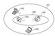
図1は、第1の実施形態における無線LANシステムの構成例を示す図である。図1において、101はIEEE 802.11b/a/g準拠の無線LANシステムにおけるアドホックネットワークを構成可能な範囲である。102は無線LANに対応し、プリンタ、ファクシミリ、スキャナ、或いはこれらの機能を複合したマルチファンクションシステム(無線LAN機能を備えた無線端末装置)である。また、無線端末装置102は、例えば子局としての機能及び親局(制御局)としての機能をそれぞれ備えているものとする。
[First Embodiment]
FIG. 1 is a diagram illustrating a configuration example of a wireless LAN system according to the first embodiment. In FIG. 1,
尚、第1の実施形態では、無線端末装置102は親局として機能し、後述する103、104、105に示す無線端末が子局として機能するものとする。
In the first embodiment, the
103は無線LAN機能を備えたデジタルカメラなどの無線端末装置であり、撮像した画像のファイルを無線接続により無線端末装置102へ転送する。104は無線LAN機能を備えたパーソナルコンピュータなどの無線端末装置であり、文書ファイルを無線接続により無線端末装置102へ転送するか、或いは無線端末装置102で読み取った原稿のファイルを無線接続により読み込む。105は無線LAN機能を備えたノート型パソコンなどの無線端末装置である。
また、無線端末装置102は、自身に接続可能な無線端末の情報として、無線端末装置103、104のMACアドレスを予め所有している。その上で、無線端末装置102は、常時一定周期で、ドメインID(SSID)を含むビーコン信号をアドホックネットワーク上の全ての無線端末装置103、104、105に対して送る。このビーコン信号に対して無線端末装置103、104、105は、自らも備えているIDを含む信号を無線端末装置102に対して接続要求として送る。そして、この場合、MACアドレスとSSIDとの両者が一致している無線端末装置(この例では、無線端末装置103、104)に対してだけ接続を許可し、特定のデータ通信の準備を行う。即ち、SSID以外に設定されたMACアドレスの一致/不一致に基づいて接続の可否を決定する。
In addition, the
ここで、第1の実施形態において、無線端末装置102と無線端末装置103との間で特定のデータ通信チャネル106が確立するまで(即ち、データリンクが確立するまで)の接続時の手順について、図1乃至図4を用いて説明する。
Here, in the first embodiment, a procedure at the time of connection until a specific
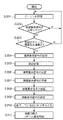
図2は、無線端末装置間における接続時のシーケンスを示す図である。また、図3は、第1の実施形態における接続時の処理を示すフローチャートである。更に、図4は、第1の実施形態における無線端末装置102の概略構成を示すブロック図である。尚、図4には、無線端末装置102の通信部のみを示しているが、装置全体を制御する制御部や上述した複数の機能を実現する複数の機能部などが含まれるのは言うまでもない。この点は、他の実施形態においても同様である。
FIG. 2 is a diagram illustrating a sequence at the time of connection between wireless terminal devices. FIG. 3 is a flowchart showing processing at the time of connection in the first embodiment. Furthermore, FIG. 4 is a block diagram showing a schematic configuration of the
まず、クリエータとしての無線端末装置102がドメインID(SSID)を含むビーコン信号をアドホックネットワーク上の全ての無線端末装置103、104、105に対して発信する(201、S301)。次に、このビーコン信号を受信した各無線端末装置から接続要求信号の受信を待つ(S302)。そして、無線端末装置103、104、105から送信元端末識別情報(例えば、MACアドレス)を含む接続要求信号をそれぞれ受信すると(S302のYES)、その送信元端末識別情報が図4に示す無線端末装置102の無線端末情報記憶部401に予め登録しておいた情報(例えば、無線端末装置103、104のMACアドレス)と一致するか否かを確認する(S303)。
First, the
ここで、送信元端末識別情報が無線端末情報(401)と一致しなければ(S303のNO)、接続要求を破棄し、次の接続要求に備える。また、送信元端末情報が無線端末情報(401)と一致すれば(S303のYES)、無線端末装置102から無線端末装置103、104へ接続要求信号の返信を行う(S304)。
If the source terminal identification information does not match the wireless terminal information (401) (NO in S303), the connection request is discarded and prepared for the next connection request. If the source terminal information matches the wireless terminal information (401) (YES in S303), a connection request signal is returned from the
次に、無線端末装置102と無線端末装置103、104との間で認証シーケンス処理が行われ(S305)、認証シーケンスが完了すると、アソシエーション処理が行われる(202、S306〜S309)。ここで、無線端末装置102は無線端末装置103、104間で特定のデータ通信チャネルが確立すると、無線端末装置102からアドホックネットワークを構成可能な範囲101内の無線端末装置103、104、105に対して発信していたSSIDを含むビーコン信号をSSIDを含まないビーコン信号に切り替える、即ちステルスモードに移行する(203、S310)。これにより、アドホックネットワークを構成可能な範囲101内から無線端末装置102の存在を隠す。
Next, an authentication sequence process is performed between the
これ以降、無線端末装置102と無線端末装置103、104間でデータ通信が可能となり(S311)、他の無線端末装置(図1に示す例では、無線端末装置105)が無線端末装置102のアドホックネットワークへ参加することが不可能となる。
Thereafter, data communication between the
尚、無線端末装置102の無線端末情報記憶部401に登録しておく情報は、装置内の不揮発性メモリに保持し、任意に書き換え可能なものでも良いし、或いは工場出荷時に、ROMに書き込まれ、その後、書き換えができないものでも良い。
Note that the information registered in the wireless terminal
第1の実施形態によれば、通信装置間で構築されるネットワークにおいて、特定の通信装置からの参加を防止し、セキュリティを向上させることができる。 According to the first embodiment, in a network constructed between communication devices, participation from a specific communication device can be prevented and security can be improved.
[第2の実施形態]
次に、図面を参照しながら本発明に係る第2の実施形態について詳細に説明する。第2の実施形態では、無線LANの機能を有し、プリンタ、ファクシミリ、スキャナ、それらの機能を複合したマルチファンクションシステムなどの無線端末装置(親機)と、これに接続することを許可されている無線端末装置群(子機)との間で特定データ通信チャネルを確立させて通信を行う無線LANシステムにおいて、無線端末装置に対して接続した、無線端末装置群の内、任意の無線端末装置(子機)の台数が、当該無線端末装置(親機)に予め設定した台数に達するまでは従来技術で最も一般的な手法を採用し、SSIDをネットワーク上に公開する。その上で、予め設定した台数に達したときに、そのSSIDをステルス化することで、任意の第三者が当該無線端末装置(親機)と任意の無線端末装置(子機)との間で確立された特定データ通信チャネルに進入してくることを困難にする無線LANシステムを提供するものである。
[Second Embodiment]
Next, a second embodiment according to the present invention will be described in detail with reference to the drawings. In the second embodiment, a wireless terminal device (parent device) having a wireless LAN function, such as a printer, a facsimile machine, a scanner, or a multifunction system that combines these functions, is permitted to connect to this. In a wireless LAN system that establishes a specific data communication channel with a wireless terminal device group (slave unit) and performs communication, an arbitrary wireless terminal device in the wireless terminal device group connected to the wireless terminal device Until the number of (slave devices) reaches the number set in advance in the wireless terminal device (master device), the most common method in the prior art is adopted and the SSID is made public on the network. In addition, when the preset number of units is reached, the SSID is converted into stealth so that an arbitrary third party can connect between the wireless terminal device (master unit) and any wireless terminal device (slave unit). The present invention provides a wireless LAN system that makes it difficult to enter a specific data communication channel established in (1).
尚、第2の実施形態における無線LANシステムの構成は、図1を用いて説明した第1の実施形態の構成と同様であり、その説明は省略する。 Note that the configuration of the wireless LAN system in the second embodiment is the same as that of the first embodiment described with reference to FIG.
ここで、無線端末装置102と無線端末装置103との間で特定のデータ通信チャネルが確立するまで(即ち、データリンクが確立するまで)の第2の実施形態における接続時の手順について、図2、図5、図6を用いて説明する。
Here, a procedure at the time of connection in the second embodiment until a specific data communication channel is established between the wireless
図5は、第2の実施形態における接続時の手順を示すフローチャートである。図6は、第2の実施形態における無線端末装置102の概略構成を示すブロック図である。
FIG. 5 is a flowchart illustrating a connection procedure in the second embodiment. FIG. 6 is a block diagram illustrating a schematic configuration of the
まず、クリエータとしての無線端末装置102がドメインID(SSID)を含むビーコン信号をアドホックネットワーク上の全ての無線端末装置103、104、105に対して発信する(201、S501)。次に、このビーコン信号を受信した各無線端末装置から接続要求信号の受信を待つ(S502)。そして、無線端末装置103、104、105から送信元端末識別情報(例えば、MACアドレス)を含む接続要求信号をそれぞれ受信すると(S502のYES)、接続要求信号を受信した無線端末装置の台数が、予め設定した台数(図6に示す接続端末台数記憶部601に記憶されている台数)に達したか否かを判定する(S503)。ここで、記憶部601に設定された台数を越えた場合、以降の接続要求を破棄し、ステップS501に戻る。記憶部601に設定された台数を越えない場合、無線端末装置102から無線端末装置103、104へ接続要求信号の返信を行う(S504)。
First, the
次に、第1の実施形態と同様に、無線端末装置102と無線端末装置103、104との間で認証シーケンス処理が行われ(S505)、認証シーケンスが完了すると、アソシエーション処理が行われる(202、S506〜S509)。ここで、無線端末装置102は無線端末装置103、104間で特定のデータ通信チャネルが確立すると、無線端末装置102からアドホックネットワークを構成可能な範囲101内の無線端末装置103、104、105に対して発信していたSSIDを含むビーコン信号をSSIDを含まないビーコン信号に切り替える、即ちステルスモードに移行する(203、S510)。これにより、アドホックネットワークを構成可能な範囲101内から無線端末装置102の存在を隠す。
Next, as in the first embodiment, authentication sequence processing is performed between the wireless
これ以降、無線端末装置102と無線端末装置103、104間でデータ通信が可能となり(S511)、他の無線端末装置(図1に示す例では、無線端末装置105)が無線端末装置102のアドホックネットワークへ参加することが不可能となる。
Thereafter, data communication is possible between the wireless
尚、図6に示す接続端末台数記憶部601に予め設定してある台数は、不揮発性メモリに保持し、任意に書き換え可能なものでも良いし、或いは工場出荷時にROMに書き込まれ、その後、書き換えができないものでも良い。
The number preset in the connected terminal
第2の実施形態によれば、無線端末装置に対して接続する無線端末装置が予め設定した台数に達したときに、データ通信サービスを享受するための準備(機密保護手段)である認証又は加入などの手順で使用されるSSIDをステルス化するので、セキュリティを高めることができる。 According to the second embodiment, when the number of wireless terminal devices connected to the wireless terminal device reaches a preset number, authentication or subscription that is preparation (security protection means) for receiving a data communication service Since the SSID used in procedures such as these is stealthed, security can be increased.
[第3の実施形態]
次に、図面を参照しながら本発明に係る第3の実施形態について詳細に説明する。第2の実施形態では、無線LANシステムが有するSSIDは予め設定した台数までネットワーク上に公開されているため、SSIDをステルス化した後も、先のSSIDを理解した任意の第三者が存在した場合、その任意の第三者が、無線端末装置に対して不正なアクセスをしてくる可能性も否定できない。
[Third Embodiment]
Next, a third embodiment according to the present invention will be described in detail with reference to the drawings. In the second embodiment, since the SSID of the wireless LAN system is disclosed on the network up to a preset number, even after making the SSID stealth, there was an arbitrary third party who understood the previous SSID. In this case, the possibility that the arbitrary third party may illegally access the wireless terminal device cannot be denied.
そこで、第3の実施形態では、SSIDをステルス化した後、先のSSIDと異なるSSIDを無線端末装置(親機)と任意の無線端末装置(子機)との間で確立された特定データ通信チャネルを使用して、無線端末装置(親機)から、暗号化してユニキャストで送信し、異なるSSIDを用いて再度無線端末装置(親機)と任意の無線端末装置(子機)との間で、新しい特定のデータ通信チャネルを確立することにより、任意の第三者が新しい特定データ通信チャネルに進入してくることを防ぐ無線LANシステムを提供するものである。 Therefore, in the third embodiment, after making the SSID stealth, a specific data communication established between the wireless terminal device (master device) and an arbitrary wireless terminal device (slave device) with an SSID different from the previous SSID. Using a channel, the wireless terminal device (base unit) encrypts it, transmits it by unicast, and again uses a different SSID between the wireless terminal device (base unit) and any wireless terminal device (slave unit). Thus, a wireless LAN system is provided that prevents any third party from entering a new specific data communication channel by establishing a new specific data communication channel.
第3の実施形態における無線LANシステムの構成は、上述した第2の実施形態の構成と同様であり、その説明は省略する。 The configuration of the wireless LAN system in the third embodiment is the same as that of the second embodiment described above, and a description thereof is omitted.
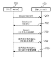
図7は、第3の実施形態における無線端末装置間のシーケンスを示す図である。第3の実施形態では、図1に示す無線端末装置102がクリエータとして動作し、無線端末装置102と特定のデータ通信チャネル106を確立した無線端末装置103がジョイナー(Joiner)として動作する。
FIG. 7 is a diagram illustrating a sequence between wireless terminal devices in the third embodiment. In the third embodiment, the
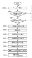
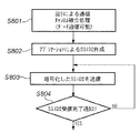
図8は、第3の実施形態におけるデータ通信可能後の処理を示すフローチャートである。まず、図5に示した第2の実施形態における通信チャネル確立処理を行い(S801)、その後、無線端末装置102と無線端末装置103とが、同じアプリケーションを動作させているとき、このアプリケーションにより、通信チャネル106を確立するのに使用したSSIDとは異なるSSIDを作成し(S802)、作成したSSIDを暗号化したものを、既に確立している通信チャネル106を使用してユニキャストで無線端末装置103に対して送信する(704、S803)。
FIG. 8 is a flowchart showing processing after data communication is possible in the third embodiment. First, communication channel establishment processing in the second embodiment shown in FIG. 5 is performed (S801), and then, when the
尚、異なるSSIDは、アプリケーション自体が作成しても良いし、図9に示すSSID記憶部901に予め設定しておいても良い。
Different SSIDs may be created by the application itself or may be preset in the
そして、無線端末装置103上で動作しているアプリケーションは、暗号化されたSSIDを受信すると、受信完了したことを示す情報を無線端末装置102に返信する(705、S804)。その後は、互いに通知しあった新規のSSIDに変更し、このSSIDを用いて無線端末装置102と無線端末装置103との間で、新しいデータ通信チャネルを確立する。
Then, when the application operating on the
第3の実施形態によれば、第2の実施形態に比べて更にセキュリティを向上させることができる。 According to the third embodiment, it is possible to further improve security compared to the second embodiment.
[第4の実施形態]
次に、図面を参照しながら本発明に係る第4の実施形態について詳細に説明する。第4の実施形態では、ステルスモードにおいて新しい特定のデータ通信チャネルで異なるSSIDを使用することで、異なるSSIDを無線端末装置(親機)と無線端末装置(子機)とにしかわからないものとし、任意の第三者にSSIDを読み取られる恐れのないセキュリティの高い無線LANシステムを提供するものである。
[Fourth Embodiment]
Next, a fourth embodiment according to the present invention will be described in detail with reference to the drawings. In the fourth embodiment, by using different SSIDs in a new specific data communication channel in the stealth mode, it is assumed that only the wireless terminal device (parent device) and the wireless terminal device (child device) can recognize different SSIDs, The present invention provides a highly secure wireless LAN system that does not allow any third party to read the SSID.
第4の実施形態における無線LANシステムの構成は、上述した第3の実施形態の構成と同様であり、その説明は省略する。 The configuration of the wireless LAN system in the fourth embodiment is the same as that of the third embodiment described above, and the description thereof is omitted.
第4の実施形態について図10乃至図12を用いて説明する。図10は、第4の実施形態における無線端末装置間のシーケンスを示す図である。図11は、第4の実施形態における処理を示すフローチャートである。図12は、第4の実施形態における無線端末装置102の概略構成を示すブロック図である。
A fourth embodiment will be described with reference to FIGS. FIG. 10 is a diagram illustrating a sequence between wireless terminal devices in the fourth embodiment. FIG. 11 is a flowchart showing processing in the fourth embodiment. FIG. 12 is a block diagram illustrating a schematic configuration of the
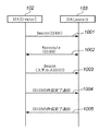
第3の実施形態と同様に、SSIDがステルス化され、通信チャネル確立処理が行われた後(1001〜1003、S1101)、無線端末装置102と無線端末装置103とが、同じアルゴリズムを使用してSSIDとは異なるSSIDを作成する。具体的には、作成するSSIDは、先のSSIDに基づいて確立した通信チャネルを用いて受信したデータから通信相手特有の情報を取得し(S1102)、その情報と、無線端末装置102及び103に予め設定してある情報とを組み合わせて(S1103)、新たなSSIDを作成する(S1104)。そして、SSID作成完了通知をユニキャストで行う(1004、S1105)。
As in the third embodiment, after the SSID is stealized and the communication channel establishment process is performed (1001 to 1003, S1101), the
その後、通信相手からSSID作成完了通知を受信すれば(1005、S1106)、作成したSSIDをお互いに共有したとみなすことができる。そして、互いに共有した新規のSSIDに変更し、このSSIDを用いて無線端末装置102と無線端末装置103との間で、新しいデータ通信チャネルを確立する。このとき、予め無線端末装置102及び103に設定してある情報(図12に示すSSID作成部1202の情報は)自身のMACアドレスやIPアドレスといった情報が考えられる。
Thereafter, if an SSID creation completion notification is received from the communication partner (1005, S1106), it can be considered that the created SSIDs are shared with each other. And it changes to the new SSID shared mutually, and a new data communication channel is established between the radio |
また、無線端末装置102が受信データから取得する固有情報(1202)には、通信相手固有の情報であるMACアドレスやIPアドレスなどが考えられる。また、これらの情報は、当該無線通信機能が備える不揮発性メモリに保持し、任意に書き換え可能なものである。
In addition, the unique information (1202) acquired from the received data by the
第4の実施形態によれば、第3の実施形態に比べて更にセキュリティを向上させることができる。 According to the fourth embodiment, security can be further improved as compared with the third embodiment.
[第5の実施形態]
次に、図面を参照しながら本発明に係る第5の実施形態について詳細に説明する。第5の実施形態では、特定データ通信チャネルを確立したとき、確立した特定データ通信チャネルでは通信サービスを行わず、データ通信チャネルとは異なるSSIDを通知し、そのSSIDを共有する無線端末装置との間で新しい通信ネットワークを構築するものである。
[Fifth Embodiment]
Next, a fifth embodiment according to the present invention will be described in detail with reference to the drawings. In the fifth embodiment, when a specific data communication channel is established, a communication service is not performed on the established specific data communication channel, an SSID different from the data communication channel is notified, and a wireless terminal device sharing the SSID A new communication network is constructed between the two.
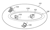
図13は、第5の実施形態における無線LANシステムの構成例を示す図である。図13において、1301はデータ通信チャネル106とは異なる特定のデータ通信チャネルである。その他の構成については、図1に示した構成と同じであり、同じ符号を付与してその説明は省略する。
FIG. 13 is a diagram illustrating a configuration example of a wireless LAN system according to the fifth embodiment. In FIG. 13,
ここで、第5の実施形態において、無線端末装置102と無線端末装置103との間で特定データ通信チャネル1301が確立するまで(即ち、データリンクが確立するまで)の接続時の手順について、図13乃至図15を用いて説明する。
Here, in the fifth embodiment, the procedure at the time of connection until the specific
図14は、第5の実施形態におけるシーケンスを示す図である。また、図15は、第5の実施形態における処理を示すフローチャートである。 FIG. 14 is a diagram illustrating a sequence according to the fifth embodiment. FIG. 15 is a flowchart showing processing in the fifth embodiment.
第5の実施形態では、第1又は第2の実施形態と同様に無線端末装置102と無線端末装置103とがSSID1を使用してアソシエーション処理を行い(1401、1402)、そのSSID1をステルス化した後(1403)、第3又は第4の実施形態と同様に、SSID1とは異なるSSID2を共有する(1404)。そして、一旦、先のSSID1に基づく通信チャネル106を切断し(1405)、ネットワーク上で両者だけが共有しているSSID2を用いて新しい通信チャネル1301を確立する(1406〜1408)。
In the fifth embodiment, as in the first or second embodiment, the
尚、無線端末装置102は発信するビーコン情報にSSID2を含まないステルスモードを使用して新しい通信チャネル1301を確立するものとする。
It is assumed that the
ここで、無線端末装置102と無線端末装置103との新しい特定データ通信チャネルを確立するまでの接続時の処理について、図15を用いて説明する。
Here, processing at the time of connection until establishing a new specific data communication channel between the wireless
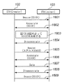
図15は、第5の実施形態における処理を示すフローチャートである。まず、無線端末装置102が特定データ通信チャネル106の確立処理を行い(S1501)、無線端末装置103へ暗号化したSSID2を送信する(S1502)。そして、無線端末装置103からSSID2受信完了通知を受信し(S1503)、SSID2を共有した状態で、無線端末装置102に予め設定した時間が経過すると、自動的にSSID1を用いて確立した通信チャネルを切断する(S1504)。
FIG. 15 is a flowchart showing processing in the fifth embodiment. First, the
その後、改めて共有したSSID2を含まないビーコンをステルスモードで発信し(S1505)、接続要求信号を送信してきた無線端末装置に対して新しい通信チャネル1301を確立する処理を実行する(1506〜1509)を行う。
After that, a beacon that does not include the shared SSID2 is transmitted again in the stealth mode (S1505), and a process of establishing a
第5の実施形態によれば、無線端末装置との間で通信されるデータの機密が漏洩することを防ぐことができ、且つ無線端末装置と確立した特定のデータ通信チャネルに第三者の侵入を防ぐことが可能となる。これにより、各々の通信チャネルにサービスの内容を限定することが可能となるため、様々な使用形態に発展させることができる。 According to the fifth embodiment, the confidentiality of data communicated with the wireless terminal device can be prevented from leaking, and a third party can enter the specific data communication channel established with the wireless terminal device. Can be prevented. As a result, it becomes possible to limit the contents of the service to each communication channel, so that it can be developed into various usage forms.
[第6の実施形態]
次に、図面を参照しながら本発明に係る第6の実施形態について詳細に説明する。第6の実施形態では、異なるSSIDを使用して無線端末装置(親機)と無線端末装置群(子機)とで形成した新しいネットワークから、無線端末装置群の任意の無線端末装置が退出した場合、即ち予め設定した接続台数より少なくなった場合、無線端末装置はステルスモードを解除し、再度元のSSIDをネットワーク上に公開する無線LANシステムを提供するものである。
[Sixth Embodiment]
Next, a sixth embodiment according to the present invention will be described in detail with reference to the drawings. In the sixth embodiment, an arbitrary wireless terminal device in the wireless terminal device group has left the new network formed by the wireless terminal device (master device) and the wireless terminal device group (slave device) using different SSIDs. In this case, that is, when the number of connected devices is less than the preset number, the wireless terminal device cancels the stealth mode and provides a wireless LAN system that releases the original SSID on the network again.
図16は、第6の実施形態における無線LANシステムの構成例を示す図である。図16において、1601は無線無線端末装置102によるアドホックネットワークの範囲で、図13に示す通信チャネル106又は新たな通信チャネル1301である。1602は参加していたアドホックネットワーク1601から外れた無線端末装置である。その他の構成については図1と同じであり、同じ符号を付与し、その説明は省略する。
FIG. 16 is a diagram illustrating a configuration example of a wireless LAN system according to the sixth embodiment. In FIG. 16,
図17は、第6の実施形態における無線端末装置のシーケンスを示す図である。図17に示すように、無線端末装置102がSSID1を含むビーコンを送信し(1701)、アソシエーション処理を行い(1702)、SSID1をステルス化し(1703)、データ通信可能となる(1704)。
FIG. 17 is a diagram illustrating a sequence of the wireless terminal device in the sixth embodiment. As shown in FIG. 17, the
この状態において、無線端末装置103が参加していた通信チャネル1601から抜け出した場合、無線端末装置102はその通信チャネル1601を切断する(1705)。そして、SSID1を含むビーコンを無線端末装置群に対して発信する(1706)。
In this state, when the
また、図18は、第6の実施形態における無線端末装置の他のシーケンスを示す図である。このシーケンスは、図16に示すアドホックネットワークの範囲1601がSSID2で構成された通信チャネル1301であった場合のシーケンスである。
FIG. 18 is a diagram illustrating another sequence of the wireless terminal device in the sixth embodiment. This sequence is a sequence when the
ここで、図18に示す1801〜1807までは、図14に示す1401〜1408と同様であり、その説明は省略する。
Here,
上述したように、データ通信が可能な状態になり、無線端末装置103が参加していた通信チャネル1601から抜け出した場合、無線端末装置102はその通信チャネル1601を切断する(1808)。そして、SSID1を含むビーコンを無線端末装置群に対して発信する(1809)。
As described above, when data communication becomes possible and the
尚、第6の実施形態では、無線端末装置103がアドホックネットワークから退出した場合を例に説明したが、無線端末装置102がアドホックネットワークを退出した場合も適用できることは言うまでもない。
In the sixth embodiment, the case where the
第6の実施形態によれば、無線端末装置がアドホックネットワークから退出したときに新しく構築したネットワークを切断し、元のネットワークを再構築することにより、無線端末装置が自動的に元のネットワークに再参加することが可能となる。 According to the sixth embodiment, when the wireless terminal device leaves the ad hoc network, the newly constructed network is disconnected and the original network is reconstructed, so that the wireless terminal device is automatically restored to the original network. It becomes possible to participate.
[第7の実施形態]
次に、図面を参照しながら本発明に係る第7の実施形態について詳細に説明する。第7の実施形態では、無線端末装置(親機)と無線端末装置群(子機)とで新しいネットワークを形成している間に、SSIDで構成された元のネットワークに無線端末装置(親機)と同じIPアドレスを割り振った無線端末装置が参加している場合に、無線端末装置(親機)が、SSIDを再度使用して元のネットワークに再参加する際に、改めてIPアドレスを振り直すことにより、IPアドレスの衝突をさけ、円滑に元のネットワークに復帰できる無線LANシステムを提供するものである。
[Seventh Embodiment]
Next, a seventh embodiment according to the present invention will be described in detail with reference to the drawings. In the seventh embodiment, while a new network is formed by the wireless terminal device (master device) and the wireless terminal device group (slave device), the wireless terminal device (master device) is added to the original network configured with the SSID. ) When a wireless terminal device to which the same IP address is assigned is participating, when the wireless terminal device (master unit) rejoins the original network using the SSID again, the IP address is reassigned. Accordingly, it is an object of the present invention to provide a wireless LAN system capable of avoiding IP address collision and smoothly returning to the original network.
図19は、第7の実施形態における無線LANシステムの構成を示す図である。図19において、1901は第6の実施形態によりSSID2のデータ通信チャネルを切断し、SSID1のビーコンを発信している状態の無線端末装置である。1902は無線端末装置1901がSSID2のデータ通信チャネルを構築している間に、無線端末装置104、105、1903で構築したSSID1のデータ通信チャネルである。
FIG. 19 is a diagram illustrating a configuration of a wireless LAN system according to the seventh embodiment. In FIG. 19,
尚、無線端末装置1903は、無線端末装置1901と同一のIPアドレス(192.168.0.2)を取得し、1902のアドホックネットワークに参加しているものとする。
It is assumed that the
ここで、第7の実施形態におけるアドホックネットワークを構築する処理を、図20を用いて説明する。 Here, the process of constructing an ad hoc network in the seventh embodiment will be described with reference to FIG.
図20は、第7の実施形態におけるシーケンスを示す図である。第6の実施形態で説明したように、データ通信可能な状態で(1901〜1907)、無線端末装置1901がアドホックネットワークを切断する(1908)。そして、元のSSID1のビーコンを発信し、元のアドホックネットワークに復帰しようとしたとき、無線端末装置1901と同一のIPアドレスを所有しているジョイナーとして機能する無線端末装置1903が復帰先のアドホックネットワークに存在する場合、無線端末装置1901は一旦自分のIPアドレスをクリアし、再度新しいIPアドレスを取得する。このとき、新しいIPアドレスはランダムでも良いし、元のIPアドレスから一定の値をインクリメントする方法やデクリメントする方法でも良い。
FIG. 20 is a diagram illustrating a sequence according to the seventh embodiment. As described in the sixth embodiment, the
そして、新しいIPアドレスを取得すると、元のSSID1を含むビーコンを無線端末装置群104、105、1903に対して発信する(1909)。
When a new IP address is acquired, a beacon including the original SSID1 is transmitted to the wireless
第7の実施形態によれば、元のネットワークに再参加するときに、IPアドレスの衝突を防ぐことが可能となる。 According to the seventh embodiment, it is possible to prevent IP address collision when rejoining the original network.
尚、本発明は複数の機器(例えば、ホストコンピュータ,インターフェース機器,リーダ,プリンタなど)から構成されるシステムに適用しても、1つの機器からなる装置(例えば、複写機,ファクシミリ装置など)に適用しても良い。 Even if the present invention is applied to a system composed of a plurality of devices (for example, a host computer, an interface device, a reader, a printer, etc.), it is applied to an apparatus (for example, a copier, a facsimile machine, etc.) composed of a single device. It may be applied.
また、本発明の目的は、前述した実施形態の機能を実現するソフトウェアのプログラムコードを記録した記録媒体を、システム或いは装置に供給し、そのシステム或いは装置のコンピュータ(CPU若しくはMPU)が記録媒体に格納されたプログラムコードを読出し実行することによっても、達成されることは言うまでもない。 Another object of the present invention is to supply a recording medium that records software program codes for realizing the functions of the above-described embodiments to a system or apparatus, and the computer (CPU or MPU) of the system or apparatus uses the recording medium as a recording medium. Needless to say, this can also be achieved by reading and executing the stored program code.
この場合、記録媒体から読出されたプログラムコード自体が前述した実施形態の機能を実現することになり、そのプログラムコードを記憶した記録媒体は本発明を構成することになる。 In this case, the program code itself read from the recording medium realizes the functions of the above-described embodiment, and the recording medium storing the program code constitutes the present invention.
このプログラムコードを供給するための記録媒体としては、例えばフロッピー(登録商標)ディスク,ハードディスク,光ディスク,光磁気ディスク,CD−ROM,CD−R,磁気テープ,不揮発性のメモリカード,ROMなどを用いることができる。 As a recording medium for supplying the program code, for example, a floppy (registered trademark) disk, a hard disk, an optical disk, a magneto-optical disk, a CD-ROM, a CD-R, a magnetic tape, a nonvolatile memory card, a ROM, or the like is used. be able to.
また、コンピュータが読出したプログラムコードを実行することにより、前述した実施形態の機能が実現されるだけでなく、そのプログラムコードの指示に基づき、コンピュータ上で稼働しているOS(オペレーティングシステム)などが実際の処理の一部又は全部を行い、その処理によって前述した実施形態の機能が実現される場合も含まれることは言うまでもない。 Further, by executing the program code read by the computer, not only the functions of the above-described embodiments are realized, but also an OS (operating system) operating on the computer based on the instruction of the program code. It goes without saying that a case where the function of the above-described embodiment is realized by performing part or all of the actual processing and the processing is included.
更に、記録媒体から読出されたプログラムコードが、コンピュータに挿入された機能拡張ボードやコンピュータに接続された機能拡張ユニットに備わるメモリに書込まれた後、そのプログラムコードの指示に基づき、その機能拡張ボードや機能拡張ユニットに備わるCPUなどが実際の処理の一部又は全部を行い、その処理によって前述した実施形態の機能が実現される場合も含まれることは言うまでもない。 Further, after the program code read from the recording medium is written in a memory provided in a function expansion board inserted into the computer or a function expansion unit connected to the computer, the function expansion is performed based on the instruction of the program code. It goes without saying that the CPU or the like provided in the board or the function expansion unit performs part or all of the actual processing and the functions of the above-described embodiments are realized by the processing.
Claims (12)
他の通信装置との間でネットワークを構築する際に、特定の通信装置とネットワークを構築したか否かを判定する判定手段と、
前記判定手段でネットワークを構築したと判定した場合に、前記ネットワークの識別子を隠蔽した報知信号を発信する手段とを有することを特徴とする通信装置。 A communication device having a function of transmitting a notification signal concealing a network identifier,
A determination means for determining whether or not a network is constructed with a specific communication device when constructing a network with another communication device;
And a means for transmitting a notification signal concealing the identifier of the network when the determination means determines that a network has been constructed.
他の通信装置との間でネットワークを構築する際に、特定の通信装置とネットワークを構築したか否かを判定する判定工程と、
前記判定工程でネットワークを構築したと判定した場合に、前記ネットワークの識別子を隠蔽した報知信号を発信する工程とを有することを特徴とする通信装置のネットワーク構築方法。 A network construction method for a communication apparatus having a function of transmitting a notification signal concealing a network identifier,
When constructing a network with other communication devices, a determination step of determining whether or not a network is constructed with a specific communication device;
And a step of transmitting a notification signal concealing the identifier of the network when it is determined that the network is established in the determination step.
Priority Applications (1)
| Application Number | Priority Date | Filing Date | Title |
|---|---|---|---|
| JP2005073951A JP2006261850A (en) | 2005-03-15 | 2005-03-15 | Communication apparatus and network buildup method thereof |
Applications Claiming Priority (1)
| Application Number | Priority Date | Filing Date | Title |
|---|---|---|---|
| JP2005073951A JP2006261850A (en) | 2005-03-15 | 2005-03-15 | Communication apparatus and network buildup method thereof |
Publications (2)
| Publication Number | Publication Date |
|---|---|
| JP2006261850A true JP2006261850A (en) | 2006-09-28 |
| JP2006261850A5 JP2006261850A5 (en) | 2008-04-24 |
Family
ID=37100634
Family Applications (1)
| Application Number | Title | Priority Date | Filing Date |
|---|---|---|---|
| JP2005073951A Withdrawn JP2006261850A (en) | 2005-03-15 | 2005-03-15 | Communication apparatus and network buildup method thereof |
Country Status (1)
| Country | Link |
|---|---|
| JP (1) | JP2006261850A (en) |
Cited By (3)
| Publication number | Priority date | Publication date | Assignee | Title |
|---|---|---|---|---|
| WO2008075626A1 (en) * | 2006-12-18 | 2008-06-26 | Feel & Tec.2 Co., Ltd. | Communication terminal authentication system and telephone system using internet |
| WO2013153617A1 (en) * | 2012-04-10 | 2013-10-17 | クラリオン株式会社 | Wireless communication system and terminal device |
| WO2018142803A1 (en) * | 2017-02-01 | 2018-08-09 | パナソニックIpマネジメント株式会社 | Wireless communication system and wireless communication device |
-
2005
- 2005-03-15 JP JP2005073951A patent/JP2006261850A/en not_active Withdrawn
Cited By (7)
| Publication number | Priority date | Publication date | Assignee | Title |
|---|---|---|---|---|
| WO2008075626A1 (en) * | 2006-12-18 | 2008-06-26 | Feel & Tec.2 Co., Ltd. | Communication terminal authentication system and telephone system using internet |
| JPWO2008075626A1 (en) * | 2006-12-18 | 2010-05-13 | 有限会社 Feel&Tec・2 | Communication terminal authentication system, Internet telephone system |
| WO2013153617A1 (en) * | 2012-04-10 | 2013-10-17 | クラリオン株式会社 | Wireless communication system and terminal device |
| JPWO2013153617A1 (en) * | 2012-04-10 | 2015-12-17 | クラリオン株式会社 | Wireless communication system and terminal device |
| US9560680B2 (en) | 2012-04-10 | 2017-01-31 | Clarion Co., Ltd. | Two terminal wireless communication system |
| WO2018142803A1 (en) * | 2017-02-01 | 2018-08-09 | パナソニックIpマネジメント株式会社 | Wireless communication system and wireless communication device |
| JPWO2018142803A1 (en) * | 2017-02-01 | 2019-11-07 | パナソニックIpマネジメント株式会社 | Wireless communication system and wireless communication apparatus |
Similar Documents
| Publication | Publication Date | Title |
|---|---|---|
| US9301328B2 (en) | Communication apparatus and communication parameter configuration method thereof | |
| EP2387205B1 (en) | Method and System for Providing Wi-Fi Service by Wi-Fi Device | |
| US7903646B2 (en) | Wireless communication system allowing group identification information to be publicly available and to be hidden, wireless access point device, and communication method and program for wireless access point device | |
| US9094424B2 (en) | Method, apparatus, and computer program product for digital stream swapping between signal sources | |
| US8806023B2 (en) | Auto-connect in a peer-to-peer network | |
| JP4956281B2 (en) | Wireless communication apparatus and control method thereof | |
| JP6141006B2 (en) | Communication device, control method, and program | |
| JP2006246433A (en) | Communication apparatus and communication method | |
| JP2009303238A (en) | Radio communication device | |
| KR20140148405A (en) | Wireless communication device, information processing device, and communication method | |
| JP2010124048A (en) | Wireless terminal device, communication method, and communication program | |
| JP2007074285A (en) | Wireless communication device, receiving device, transmitting device, and communication control program | |
| JP2003188885A (en) | Communication system, server device, client device, method for controlling them, programs for performing them, and computer readable storage medium stored with the programs | |
| JP2016525804A (en) | Method and apparatus for performing a wireless docking service | |
| CN102342153A (en) | Methods and apparatus for automated local network formation using alternate connected interfaces | |
| TW200841642A (en) | Personal area network implementation within an infrastructure network | |
| JP2009027514A (en) | Communication device, its communication method, program, and storage medium | |
| JP6312369B2 (en) | COMMUNICATION DEVICE, COMMUNICATION DEVICE CONTROL METHOD, PROGRAM | |
| JP6015315B2 (en) | Communication device | |
| JP2014183340A (en) | Radio communication system and radio communication device | |
| JP2006261850A (en) | Communication apparatus and network buildup method thereof | |
| KR20150047278A (en) | Image display apparatus for conducting auto wireless communication among devices and image displaying method thereof | |
| JP5197060B2 (en) | COMMUNICATION DEVICE, COMMUNICATION METHOD, PROGRAM, AND STORAGE MEDIUM | |
| JP2007184762A (en) | Communication method of wireless communication system, and wireless communication device | |
| JP2015023539A (en) | Radio communication device |
Legal Events
| Date | Code | Title | Description |
|---|---|---|---|
| A521 | Written amendment |
Free format text: JAPANESE INTERMEDIATE CODE: A523 Effective date: 20080307 |
|
| A621 | Written request for application examination |
Free format text: JAPANESE INTERMEDIATE CODE: A621 Effective date: 20080307 |
|
| A761 | Written withdrawal of application |
Free format text: JAPANESE INTERMEDIATE CODE: A761 Effective date: 20100208 |