EP2387205B1 - Method and System for Providing Wi-Fi Service by Wi-Fi Device - Google Patents
Method and System for Providing Wi-Fi Service by Wi-Fi Device Download PDFInfo
- Publication number
- EP2387205B1 EP2387205B1 EP11166050.2A EP11166050A EP2387205B1 EP 2387205 B1 EP2387205 B1 EP 2387205B1 EP 11166050 A EP11166050 A EP 11166050A EP 2387205 B1 EP2387205 B1 EP 2387205B1
- Authority
- EP
- European Patent Office
- Prior art keywords
- electronic device
- counterpart electronic
- counterpart
- information
- devices
- Prior art date
- Legal status (The legal status is an assumption and is not a legal conclusion. Google has not performed a legal analysis and makes no representation as to the accuracy of the status listed.)
- Active
Links
Images


Classifications
-
- H—ELECTRICITY
- H04—ELECTRIC COMMUNICATION TECHNIQUE
- H04W—WIRELESS COMMUNICATION NETWORKS
- H04W12/00—Security arrangements; Authentication; Protecting privacy or anonymity
- H04W12/06—Authentication
-
- H—ELECTRICITY
- H04—ELECTRIC COMMUNICATION TECHNIQUE
- H04W—WIRELESS COMMUNICATION NETWORKS
- H04W84/00—Network topologies
- H04W84/02—Hierarchically pre-organised networks, e.g. paging networks, cellular networks, WLAN [Wireless Local Area Network] or WLL [Wireless Local Loop]
- H04W84/10—Small scale networks; Flat hierarchical networks
- H04W84/12—WLAN [Wireless Local Area Networks]
-
- H—ELECTRICITY
- H04—ELECTRIC COMMUNICATION TECHNIQUE
- H04L—TRANSMISSION OF DIGITAL INFORMATION, e.g. TELEGRAPHIC COMMUNICATION
- H04L63/00—Network architectures or network communication protocols for network security
- H04L63/08—Network architectures or network communication protocols for network security for authentication of entities
- H04L63/0853—Network architectures or network communication protocols for network security for authentication of entities using an additional device, e.g. smartcard, SIM or a different communication terminal
-
- H—ELECTRICITY
- H04—ELECTRIC COMMUNICATION TECHNIQUE
- H04L—TRANSMISSION OF DIGITAL INFORMATION, e.g. TELEGRAPHIC COMMUNICATION
- H04L67/00—Network arrangements or protocols for supporting network services or applications
- H04L67/50—Network services
- H04L67/51—Discovery or management thereof, e.g. service location protocol [SLP] or web services
-
- H—ELECTRICITY
- H04—ELECTRIC COMMUNICATION TECHNIQUE
- H04W—WIRELESS COMMUNICATION NETWORKS
- H04W12/00—Security arrangements; Authentication; Protecting privacy or anonymity
- H04W12/50—Secure pairing of devices
-
- H—ELECTRICITY
- H04—ELECTRIC COMMUNICATION TECHNIQUE
- H04W—WIRELESS COMMUNICATION NETWORKS
- H04W8/00—Network data management
- H04W8/005—Discovery of network devices, e.g. terminals
-
- H—ELECTRICITY
- H04—ELECTRIC COMMUNICATION TECHNIQUE
- H04W—WIRELESS COMMUNICATION NETWORKS
- H04W80/00—Wireless network protocols or protocol adaptations to wireless operation
- H04W80/04—Network layer protocols, e.g. mobile IP [Internet Protocol]
-
- H—ELECTRICITY
- H04—ELECTRIC COMMUNICATION TECHNIQUE
- H04W—WIRELESS COMMUNICATION NETWORKS
- H04W92/00—Interfaces specially adapted for wireless communication networks
- H04W92/16—Interfaces between hierarchically similar devices
- H04W92/18—Interfaces between hierarchically similar devices between terminal devices
Definitions
- the present invention relates to a Wireless Fidelity (Wi-Fi) device. More particularly, the present invention relates to a method and a system in which Wi-Fi devices share support information on functions that they support by transmitting/receiving the support information to/from each other and provide Wi-Fi services based on the shared support information.
- Wi-Fi Wireless Fidelity
- a mobile communication terminal has various additional functions, which include a Television (TV) viewing function (e.g. mobile broadcasting such as Digital Multimedia Broadcasting (DMB) or Digital Video Broadcasting (DVB)), a music playback function (e.g. Moving Picture Experts Group Audio Layer-3 (MP-3), a function for taking photos, a Wi-Fi connection function, etc., as well as typical communication functions (e.g. a voice phone call and message transmission/reception).
- TV Television
- DMB Digital Multimedia Broadcasting
- DVD Digital Video Broadcasting
- MP-3 Moving Picture Experts Group Audio Layer-3
- typical communication functions e.g. a voice phone call and message transmission/reception.
- Wi-Fi Wireless Local Area Network
- AP Access Point
- Wi-Fi Wireless Fidelity
- a portable terminal supporting the Wi-Fi provides a Wi-Fi Protected Setup (WPS) function for simple and easy settings from a wireless connection to a security setting.
- WPS Wi-Fi Protected Setup
- each Wi-Fi device currently provides a function capable of setting a secure connection between Wi-Fi devices by pressing a particular button assigned by the WPS function or by directly inputting a given PIN code.
- the above WPS function is not widely recognized by general users. Also, the WPS function has the inconvenience of requiring a user to manually press a particular assigned button or manually input multiple digits of a Personal Identification Number (PIN) code. Further, each portable convergence terminal, which has recently been propagated, requires a new process for a Wi-Fi connection in addition to the existing convergence function. Accordingly, inconvenience is caused to users of the portable convergence terminals.
- PIN Personal Identification Number
- US 2004/205246 describes a method for identifying devices in a wireless LAN home network.
- US 2005/078644 describes a technique for service discovery in a wireless network.
- US 2009/104875 describes a technique for establishing a communication link between a plurality of networked electronic devices that communicate using a short-range wireless communication protocol.
- an aspect of the present invention is to provide a method and a system in which Wireless Fidelity (Wi-Fi) devices can exchange information with each other regarding functions that they support.
- Wi-Fi Wireless Fidelity
- Another aspect of the present invention is to provide a control method by which a Wi-Fi device can select an optimal counterpart Wi-Fi device supporting functions of a Wi-Fi service-based application when the Wi-Fi device executes the Wi-Fi service-based application.
- Another aspect of the present invention is to provide a method and a system in which a Wi-Fi device can provide services by rapidly selecting and setting a connection to an optimal counterpart Wi-Fi device for operating a Wi-Fi service-based application based on support information provided by other Wi-Fi devices.
- Another aspect of the present invention is to provide a method and a system capable of selecting an optimal counterpart Wi-Fi device from multiple counterpart Wi-Fi devices by checking the received signal intensities of the multiple counterpart Wi-Fi devices during automatic connection setting of a Wi-Fi Protected Setup (WPS) function according to automatic authentication between the Wi-Fi devices.
- WPS Wi-Fi Protected Setup
- Another aspect of the present invention is to provide a method and a system that can implement an optimal Wi-Fi service environment capable of providing the user convenience of using a Wi-Fi service by enabling Wi-Fi devices to share information supported by themselves with each other.
- Another aspect of the present invention is to provide a method and a system that improve the usability and convenience of a Wi-Fi device by automatically selecting an optimal counterpart Wi-Fi device capable of using a particular Wi-Fi based service.
- an electronic device for providing a Wireless Fidelity, Wi-Fi, service according to the disclosure of the appended claim 6.
- a Wi-Fi Protected Setup (WPS) function for simple and easy settings from a wireless connection to a security setting can be extended without a complicated setting process in a Wi-Fi device.
- a user can set a connection between Wi-Fi devices by pressing a particular button assigned to a Wi-Fi device or by inputting a given Personal Identification Number (PIN) code through the Wi-Fi device in order to use a WPS function.
- PIN Personal Identification Number
- exemplary embodiments of the present invention enable automatic authentication without the intervention of a user when the use of a WPS function is desired.
- Wi-Fi devices can transmit information to each other regarding functions that they support, so that each of the Wi-Fi devices can recognize the information regarding functions supported by a counterpart Wi-Fi device.
- exemplary embodiments of the present disclosure propose an apparatus and a control method, in which a Wi-Fi device can determine an optimal counterpart Wi-Fi device among multiple counterpart Wi-Fi devices during automatic connection setting of the WPS function according to automatic authentication between the Wi-Fi devices based on the support information. Therefore, an exemplary apparatus and control method proposed by the present disclosure can more simply and easily support a Wi-Fi service.
- FIGs. 1 to 11B an exemplary configuration of a Wi-Fi device and a method for controlling the operation thereof will be described with reference to FIGs. 1 to 11B .
- the configuration of a Wi-Fi device and a method for controlling the operation thereof are not limited to the following description and can be applied to various embodiments based on the following description.
- FIG. 1 is a schematic view illustrating the configuration of a system for describing an operation according to an exemplary embodiment of the present invention.
- a system of the present invention includes a Wi-Fi device (hereinafter, referred to as a "transmission device”) 100 functioning as a transmitter, and a Wi-Fi device (hereinafter, referred to as a "reception device”) 200 functioning as a receiver.
- a transmission device and a reception device are discriminated from each other for convenience of description.
- the reception device 200 may represent multiple Wi-Fi devices.
- the reception device 200 may be any of various electronic apparatuses including a music playback player, a display apparatus, a portable game terminal, a printer, etc, each of which includes a built-in Wi-Fi module.
- the reception device 200 will be described as any one or multiple ones among the various electronic apparatuses as described above.
- the transmission device 100 may also include any of various electronic apparatuses including a music playback player, a display apparatus, a portable game terminal, a printer, etc, each of which includes a built-in Wi-Fi module.
- the transmission device 100 is illustrated in FIG. 1 as a mobile communication terminal.
- the Wi-Fi based system may support a Wi-Fi direct function between the transmission device 100 and the reception device 200, and the transmission device 100 and the reception device 200 may be directly interconnected in a Direct Access (DA) mode.
- DA Direct Access
- FIG. 1 illustrates the relation of setting a connection between the Wi-Fi devices 100 and 200 in the DA mode.
- the Wi-Fi devices 100 and 200 located within a short distance of each other may be directly interconnected in the DA mode by using Wi-Fi modules, instead of being connected through an Access Point (AP).
- AP Access Point
- the Wi-Fi devices 100 and 200 may exchange information with each other regarding functions that they support. For example, when a user executes a Wi-Fi service-based application in the transmission device 100, the transmission device 100 identifies support information transmitted from the reception device 200. Then, as an example, the transmission device 100 can first select reception devices, which have been manufactured by the same manufacturer as that of the transmission device 100, with reference to the identified support information. When the number of reception devices selected by the first selection is greater than one, the transmission device 100 may secondly select reception devices capable of supporting a Wi-Fi service according to the executed application among the multiple first-selected reception devices.
- the transmission device 100 may determine an optimal reception device for the Wi-Fi service among the multiple secondly-selected reception devices by checking multiple pieces of signal information (e.g. received signal intensities) from the secondly-selected reception devices. Then, data related to the executed application is transmitted to the determined reception device, so that the application may be executed in the determined reception device.
- An exemplary method for transmitting support information and determining a final counterpart device as described above, and a control method thereof, which is related to the above method, will be described with reference to the drawings described below.
- FIG. 1 illustrates the configuration of the system in which the Wi-Fi devices 100 and 200 are interconnected in the DA mode.
- the Wi-Fi devices 100 and 200 are not limited to a connection in the DA mode.
- the Wi-Fi devices 100 and 200 may have a configuration for a system using a Wireless Local Area Network (WLAN), or a system configuration for interconnection between the Wi-Fi devices 100 and 200 through an AP.
- WLAN Wireless Local Area Network
- the Wi-Fi devices 100 and 200 include Wi-Fi modules and may be connected to an Internet network through a repeater (e.g. a router) via an AP in a hotspot area.
- the Wi-Fi devices 100 and 200 may be connected to the Internet network via a mobile communication network in an area that is not equipped with the AP.
- the Wi-Fi devices 100 and 200 may be set to be interconnected through the APs for data transmission/reception.
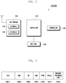
- FIG. 2 is a block diagram schematically illustrating a configuration of a Wi-Fi device according to an exemplary embodiment of the present invention.
- the configuration of a Wi-Fi device as illustrated in FIG. 2 may be commonly applied to both the transmission device 100 and the reception device 200 as described above with reference to FIG. 1 .
- a Wi-Fi device includes a Wi-Fi module 110, an input unit 120, a storage unit 130, and a control unit 140.
- the Wi-Fi device may include various configurations, depending on the form thereof.
- the Wi-Fi device may further include a display unit for displaying screen data, a Radio Frequency (RF) module for performing a mobile communication function, an audio processor having a microphone (MIC) and a speaker (SPK), a camera module for capturing still or moving images, a digital broadcasting module for receiving and reproducing digital broadcasting (e.g. mobile broadcasting such as Digital Multimedia Broadcasting (DMB) or Digital Video Broadcasting (DVB)), and a Bluetooth communication module for performing a Bluetooth communication function.
- RF Radio Frequency
- MIC microphone
- SPK speaker
- a camera module for capturing still or moving images
- DMB Digital Multimedia Broadcasting
- DVD Digital Video Broadcasting
- Bluetooth communication module for performing a Bluetooth communication function.
- the above Wi-Fi module 110 supports Internet Protocol (IP)-based mobile communication of the Wi-Fi device.
- the Wi-Fi module 110 includes an AP module 113 and a station (STA) module 115.
- the Wi-Fi module 110 may operate in an AP mode by waking the AP module 113 or may operate in a non-AP mode (i.e. an STA mode) by waking the STA module 115.
- the non-AP mode i.e. the STA mode refers to a mode in which a Wi-Fi device operates depending on the function of a device side when providing a Wi-Fi based service.
- the non-AP mode may refer to a mode in which a Wi-Fi device operates as the transmission device 100 as described above with reference to FIG. 1 .
- the AP mode refers to a mode in which the Wi-Fi device operates depending on the function of an AP side when providing the Wi-Fi based service.
- the AP mode may refer to a mode in which a Wi-Fi device operates as the reception device 200 as described above with reference to FIG. 1 .
- the AP mode and the non-AP mode i.e. the STA
- the STA the non-AP mode
- the Wi-Fi module 110 transmits support information regarding functions supported by the Wi-Fi device according to the control of the controller 140 in the AP mode of the Wi-Fi device. For example, the Wi-Fi module 110 may periodically broadcast a beacon message, which includes the support information of the Wi-Fi device, through the AP module 113 in the AP mode. Otherwise, in the AP mode, the Wi-Fi module 110 may receive a request message (e.g. a probe request message) from another Wi-Fi device (e.g. the transmission device 100 illustrated in FIG. 1 ) which operates in the non-AP mode, and then provide the received request message to the control unit 140. In response, the Wi-Fi module 110 may transmit a message (e.g. a probe response message), which includes the support information of the Wi-Fi device and is provided by the control unit 140, through the AP module 113.
- a request message e.g. a probe request message
- the Wi-Fi module 110 may transmit a message (e.g. a probe response message), which includes the support information
- the Wi-Fi module 110 may transmit a probe request message as described above to another Wi-Fi device (e.g. the reception device 200 illustrated in FIG. 1 ), which operates in the AP mode, through the STA module 115 in the non-AP mode of the Wi-Fi device. Then, the Wi-Fi module 110 may receive a beacon message or a probe response message as described above, which includes support information of another Wi-Fi device operating in the AP mode and is transmitted from the other Wi-Fi device, through the STA module 115, and provide the received beacon message or probe response message to the control unit 140. Next, the Wi-Fi module 120 may transmit/receive an automatic authentication request message and an automatic authentication response message as described below.
- another Wi-Fi device e.g. the reception device 200 illustrated in FIG. 1
- the Wi-Fi module 110 may receive a beacon message or a probe response message as described above, which includes support information of another Wi-Fi device operating in the AP mode and is transmitted from the other Wi-Fi device, through the STA module 115, and provide the
- the input unit 120 detects a handling action of a user and generates an input signal corresponding to the detected handling action.
- the input unit 120 provides the generated input signal to the control unit 140.
- the input unit 120 may include multiple buttons. More particularly, the input unit 120 may include at least one button for generating a user input signal related to the execution (e.g. performing a WPS function for setting a connection between Wi-Fi devices) of a Wi-Fi function for using a Wi-Fi based service.
- the storage unit 130 stores various programs and data executed and processed by the Wi-Fi device. It may include at least one volatile memory device and at least one nonvolatile memory device. For example, the storage unit 130 may continually or temporarily store an operating system of the Wi-Fi device, programs and data related to a control operation for an AP mode by the Wi-Fi module 110, programs and data related to a control operation for a non-AP mode (i.e. an STA mode) by the Wi-Fi module 110, programs and data related to a control operation for an automatic authentication function in the Wi-Fi device, programs and data related to a control operation for the transmission function of support information of the Wi-Fi device, programs and data related to a control operation for the function of determining an optimal counterpart Wi-Fi device by using signal information (e.g.
- the storage unit 130 may store a threshold for determining an optimal counterpart Wi-Fi device. Also, the storage unit 130 may store an information table for providing the support information of the Wi-Fi device. In this specification, the information table may be constructed as illustrated in FIGs. 11A and 11B .
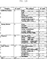
- FIGs. 11A and 11B are an illustrative view showing an information table according to an exemplary embodiment of the present invention.
- the information table includes a category field indicating a device type (e.g. Telephone, Computer, Printers, etc.) to which a Wi-Fi device belongs, an Identifier (ID) value field indicating an identifier (e.g. 10) for identifying a relevant Category (e.g. Telephone), a Sub-category field indicating information (i.e. a convergence function, capability, Windows Mobile, Phone-single mode, Phone-dual mode, etc.) supported by a device belonging to the relevant Category (e.g. Telephone), an ID value field indicating an identifier (e.g. 1, 2 or 3) for identifying each piece of information supported by a relevant Sub-category, etc.
- ID Identifier
- the information table may include a single category (e.g. Telephone) among the Category items as described above depending on the type of a Wi-Fi device, and may include an ID value for the Category, and sub-categories and ID values for the Sub-categories.
- the information table may be constructed as illustrated in Table 1 below for the category "Telephone" among the illustrations shown in FIGs. 11A and 11B .
- the information table includes information on Sub-categories which may change depending on functions supported by the relevant Wi-Fi device in Table 1 below.
- Table 1 Category ID value Sub-category ID value Telephone 10 Windows mobile 1 Phone-single mode 2 Phone-dual mode 3 Smartphone-single mode 4 Smartphone-dual mode 5
- the control unit 140 controls overall operations of the Wi-Fi device.
- the control unit 140 may control an operation related to functions for providing a Wi-Fi based service of the Wi-Fi device.
- the control unit 140 may control an operation related to the automation of a WPS function of the Wi-Fi device.
- the control unit 140 may control the automation of the WPS function through an automatic authentication function in the Wi-Fi device.
- the control unit 140 may control operation of the Wi-Fi module 110 by set periods.
- the control unit 140 may wake the AP module 113 of the Wi-Fi module 110 or may wake the STA module 115 of the Wi-Fi module 110 by the set periods.
- control unit 140 may control an operation related to the AP mode and the non-AP mode (i.e. the STA mode) of the Wi-Fi device according to an operating scheme of the Wi-Fi module 110. For example, when the Wi-Fi device operates in the AP mode and periodically broadcasts a beacon message at beacon intervals, the control unit 140 may include manufacturer information of the Wi-Fi device and support information on functions and capability supported by the Wi-Fi device in the beacon message, and may transmit the beacon message including them. Also, when the Wi-Fi device operates in the AP mode and receives a probe request message from a counterpart Wi-Fi device operating in the non-AP mode (i.e.
- the control unit 140 may include manufacturer information of the Wi-Fi device and support information on functions and capability supported by the Wi-Fi device in a probe response message corresponding to the received probe request message, and may transmit the probe response message including them to the counterpart Wi-Fi device.
- the control unit 140 may check support information included in the relevant beacon message or probe response message, and may confirm functions and capability supported by the counterpart Wi-Fi device. More particularly, when the Wi-Fi device executes an application according to the Wi-Fi based service, the control unit 140 may determine an optimal counterpart Wi-Fi device for the Wi-Fi based service corresponding to the executed application based on the support information obtained from the counterpart Wi-Fi device as described above. For example, the control unit 140 may first select reception devices of the same manufacturer based on the support information of the beacon messages or probe response messages.
- the control unit 140 may secondly select reception devices capable of supporting the particular requested service among the multiple first-selected reception devices.
- the control unit 140 may determine a final counterpart Wi-Fi device for the Wi-Fi service among the multiple secondly-selected reception devices by checking multiple pieces of signal information (e.g. received signal intensities) from the secondly-selected reception devices.
- the control unit 140 may control operating of the Wi-Fi based service according to the determined counterpart Wi-Fi device and the executed application. For example, when an application related to video data reproduction is executed, the control unit 140 may determine a counterpart Wi-Fi device having a video data output function, by checking the obtained support information. Thereafter, the control unit 140 transmits the video data to the determined counterpart Wi-Fi device, so that the determined counterpart Wi-Fi device can output the received video data.
- the control unit 140 may control connection setting according to the transmission/reception of an automatic authentication request message and an automatic authentication response message as described below. For example, when the Wi-Fi device operates in the non-AP mode, the control unit 140 may control transmitting of the automatic authentication request message, which includes a PIN code or a button input command code, to a counterpart Wi-Fi device in a scheme defined for a WPS function. Also, when the Wi-Fi device operates in the AP mode and receives an automatic authentication request message, the control unit 140 may automatically input the PIN code for the WPS function or may activate the button input for the WPS function according to the PIN code or the button input command code included in the received automatic authentication request message, and may control the transmission of an automatic authentication response message.
- the control unit 140 may control connection setting according to the transmission/reception of an automatic authentication request message and an automatic authentication response message as described below. For example, when the Wi-Fi device operates in the non-AP mode, the control unit 140 may control transmitting of the automatic authentication request message, which includes a PIN code or
- Wi-Fi devices of the same manufacturer may mutually transmit/receive an automatic authentication request message and an automatic authentication response message based on support information defined in a beacon message or a probe response message. Namely, it is possible to set a connection between the Wi-Fi devices according to the automation of the WPS function according to automatic authentication by the transmission/reception of the messages between the Wi-Fi devices of the same manufacturer based on the support information.
- the control unit 140 will be described in more detail regarding a method for operation control as described below.
- the control unit 140 also performs various control operations related to typical functions of the Wi-Fi device. For example, when a communication function using a mobile communication network is executed in the Wi-Fi device, the control unit 140 may control operating of the communication function according to the execution of the application. Also, when an application of a communication function using a local network is executed in the Wi-Fi device, the control unit 140 may control operating of the communication function according to the execution of the application.
- the Wi-Fi devices illustrated in FIGs. 1 and 2 may include all types of information communication apparatuses, all types of multimedia apparatuses, and application apparatuses for all types of information communication apparatuses and all types of multimedia apparatuses.
- the Wi-Fi device may include small devices, such as a mobile communication terminal, a smart phone, a Portable Multimedia Player (PMP), a digital broadcasting player, a Personal Digital Assistant (PDA), a music player (e.g. an MP3 player), and a portable game terminal, which operate by communication protocols corresponding to various communication systems.
- PMP Portable Multimedia Player
- PDA Personal Digital Assistant
- music player e.g. an MP3 player
- portable game terminal which operate by communication protocols corresponding to various communication systems.
- the Wi-Fi device may be operated as a medium or large device, such as a Television (TV), a Large Format Display (LFD), a Digital Signage (DS), a media pole, a Personal Computer (PC), a notebook, a printer, and a combination apparatus.
- TV Television
- LFD Large Format Display
- DS Digital Signage
- PC Personal Computer
- FIG. 3 is an illustrative view showing a message format used to transmit support information of another Wi-Fi device according to an exemplary embodiment of the present invention.
- each of a beacon message and a probe response message as described above includes an Organizationally Unique Identifier (OUI) field 301, a Len (Length) field 303, an ID (Identifier) field 305, a Version field 307, a Type field 309, a Value field 311, and a Service Protocol Type field 313.
- OMI Organizationally Unique Identifier
- ID Identifier
- the OUI field 301 represents a service information field for defining service support information.
- the OUI field 301 may have a value indicating manufacturer information of a Wi-Fi device.
- the OUI field 301 may have a value of "00 00 F0" for Samsung Electronics Co., Ltd.
- the OUI field 301 has a unique value assigned to each manufacturer.
- the OUI field 301 may include not only the manufacturer information as described above but also support information on functions and capability supported by the Wi-Fi device. Also, in the OUI field 301, support information on particular service information requested by a particular Wi-Fi device may be additionally defined.
- the OUI field 301 may be used to indicate that the relevant Wi-Fi device supports a WPS function according to automatic authentication, which is employed by Wi-Fi devices of the same manufacturer, and to enable the Wi-Fi devices to recognize the functions supportable by the Wi-Fi devices.
- An exemplary operation for transmitting/receiving a message including the OUI field 301 will be described below.
- the Len field 303 represents a field for recording the entire size of a beacon message or a probe response message.
- the ID field 305 is used to prevent the duplication of the value of the OUI field 301 as described above, and represents a field of a state where a particular value is not determined.
- the Version field 307 represents a field for extension, and may be a field defined depending on the form change of a message used in a Wi-Fi based system.
- the Type field 309 represents a field for defining the type of a beacon message or a response message. The Type field 309 may be defined to indicate "resolved” for "0000,” “advertise” for "0001,” "WPS start request” for "0010,” and "WPS response” for "0011.”
- the Value field 311 represents a field for defining a value for a Category of a Wi-Fi device and values for Sub-categories supported within the relevant Category based on the information table as described above. Namely, the Value field 311 is used to define an apparatus Category and Sub-categories of the Wi-Fi device. Therefore, the Value field 311 may have a value indicating which Category the relevant Wi-Fi device belongs to, and may have values indicating information on particular functions and capability supported by the relevant Wi-Fi device. For example, the Value field 311 may have a value indicating that the Wi-Fi device belongs to Audio Devices and values indicating a particular function and capability among the Audio Devices. Each value defined in the Value field 311 may be defined by previously classifying devices according to Categories as described with reference to Table 1.
- the Service Protocol Type field 313 is used to define the protocol type of a wireless environment for transmitting/receiving a probe response message.
- the Service Protocol Type field 313, for example, may be defined to indicate "all service protocol types” for "00000000,” “bonjour” for "00000001,” “UPnP” for "00000010,” “ws-discovery” for "00000011,” and “vendor specific” for "11111111.” Also, a value, which is still not defined in the Service Protocol Type field 313, has a state of "reserved.”
- a message (e.g. a beacon message or a probe response message) defined in an exemplary embodiment of the present invention may indicate which manufacturer has made a Wi-Fi device in the OUI field 301 as described above. Also, the OUI field 301 or the Value field 311 may be used to indicate which functions and capability are supported by the Wi-Fi device. An exemplary method for using these messages will be described below.
- the first scan process is a passive scan method.
- the passive scan method corresponds to a method for using a beacon message transmitted by a Wi-Fi device operating in an AP mode.
- the beacon message indicates a value transmitted by the Wi-Fi device in the AP mode.
- the beacon message makes it possible to periodically broadcast the existence and support capability (e.g. a signal intensity and a usable bit-rate) of the Wi-Fi device in the AP mode to nearby Wi-Fi devices.
- a Wi-Fi device operating in a non-AP mode i.e.
- an STA mode may obtain various pieces of information necessary to connect to a network through the candidate Wi-Fi devices, and/or service type information and capability information provided by the candidate Wi-Fi devices, etc., along with a list of the candidate Wi-Fi devices transmitting beacon messages.
- the second scan process is an active scan method.
- a Wi-Fi device in the non-AP mode requiring connection setting first transmits a probe request message to a counterpart Wi-Fi device in an AP mode.
- the probe request message may include particular service information requested by the Wi-Fi device in the non-AP mode.
- the Wi-Fi device in the AP mode which has received the probe request message, transmits a probe response message as a response to the probe request message to the Wi-Fi device in the non-AP mode.
- the probe response message may include various pieces of information necessary for a direct Wi-Fi connection. Accordingly, the Wi-Fi device in the non-AP mode may obtain a list of candidate Wi-Fi devices through the received probe response message.
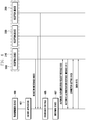
- FIG. 4 is a signal flow diagram illustrating an operation for a Wi-Fi based service between Wi-Fi devices according to an exemplary embodiment of the present invention.
- the transmission device 100 corresponds to a Wi-Fi device operating in the non-AP mode (i.e. the STA mode) and the reception devices 200 correspond to multiple Wi-Fi devices operating in the AP mode, as described above.
- the transmission device 100 may receive as input the execution of a Wi-Fi based application in step 401. Then, the transmission device 100 may receive a beacon message which is periodically transmitted by each of the reception devices 200 existing around the transmission device 100 in step 403. Each of the reception devices 200 may periodically broadcast a beacon message. Accordingly, the transmission device 100 may receive each beacon message before or after executing an application in step 401. Namely, each beacon message may be periodically broadcast by the Wi-Fi device in the AP mode as described above, so that the Wi-Fi device in the non-AP mode may periodically receive each beacon message in response.
- each of the reception devices 200 may include manufacturer information and information on functions that they support and on their capabilities in an OUI field of the beacon message, and may transmit the beacon message.
- each of the reception devices 210 and 230 may define the above information in the OUI field of the beacon message, and may transmit the beacon message including the above information.
- the typical reception device 250 may transmit a usual beacon message following a standard protocol.
- each of the reception devices 200 may define a category and sub-categories of the relevant reception device in a Value field of the beacon message, and may transmit the beacon message including them.
- the transmission device 100 may check the OUI field of each beacon message in step 405. Then, the transmission device 100 may determine reception devices (e.g. the reception devices 210 and 230), each of which has the same manufacturer information as the transmission device 100 and supports a service corresponding to the executed application, with reference to the support information defined in the OUI field of each beacon message as described above in step 407. For example, the transmission device 100 may select counterpart devices, which have been manufactured by the same manufacturer as that of the transmission device 100, with reference to the OUI field of each received beacon message, and may select a counterpart device supporting a requested service among the selected counterpart devices. When there are multiple counterpart devices (e.g.
- the transmission device 100 may check two pieces of signal information (e.g. received signal intensities) of the relevant reception devices 210 and 230. Next, the transmission device 100 may select a reception device having signal information which has a value (e.g. signal intensity) equal to or greater than a threshold. When the number of counterpart devices, each of which has signal information having a value equal to or greater than the threshold, is also greater than one, the transmission device 100 may determine a counterpart device having the largest value in the signal information as a final counterpart device. The determination of a final counterpart device will be described in an exemplary method for operation control below. The case where the determined final counterpart device is the reception device 210 will be illustratively described below.
- the transmission device 100 transmits an automatic authentication request message for setting a Wi-Fi connection to the determined reception device 210 in step 409.
- the automatic authentication request message refers to a message for requesting automatic connection setting according to automatic authentication by a standard previously and mutually agreed upon by devices of the same manufacturer based on information defined in an OUI field.
- the automatic authentication request message may include a PIN code or a button input command code for wireless encryption setting in a PIN scheme or in a Push Button Configuration (PBC) scheme.
- PBC Push Button Configuration
- the reception device 210 When receiving the automatic authentication request message, the reception device 210 transmits an automatic authentication response message as a response to the received automatic authentication request message to the transmission device 100 in step 411. For example, when receiving the automatic authentication request message, the reception device 210 may set connection to the transmission device 100 in response to an automatic input using a PIN code included in the automatic authentication request message in the PIN scheme, and may transmit an automatic authentication response message as a response to the received automatic authentication request message to the transmission device 100.
- the reception device 210 may set a connection to the transmission device 100 by automatically activating a button corresponding to a WPS function by a button input command code included in the received automatic authentication request message in the PBC scheme, and may transmit an automatic authentication response message as a response to the received automatic authentication request message to the transmission device 100.
- the transmission device 100 and the reception device 210 may establish a communication channel for Wi-Fi communication by transmitting/receiving the automatic authentication request message and the automatic authentication response message as described above, and may complete interconnection setting in step 413.
- the transmission device 100 may transmit data, which corresponds to the application executed in step 401, to the reception device 210 in step 415.
- the transmission device 100 requests video data reproduction and the reception device 210 is a display apparatus capable of outputting screen data.
- the transmission device 100 may transmit the video data to the reception device 210 through the established communication channel.
- the reception device 210 may display the received video data through a display unit thereof.
- FIG. 5 is a signal flow diagram illustrating an operation for a Wi-Fi based service between Wi-Fi devices according to an exemplary embodiment of the present invention.
- the transmission device 100 corresponds to a Wi-Fi device operating in the non-AP mode (i.e. the STA mode) and the reception devices 200 correspond to multiple Wi-Fi devices operating in the AP mode, as described above.
- the transmission device 100 may receive as input the execution of a Wi-Fi based application in step 501. Then, the transmission device 100 broadcasts probe request messages in order to scan Wi-Fi devices existing around the transmission device 100 in step 503.
- a probe request message may include a particular service (e.g. request function information on the execution, reproduction, output, storage, etc. of data corresponding to the executed application) requested by a Wi-Fi device (e.g. the transmission device 100) in the non-AP mode.
- each of the reception devices 200 When receiving the probe request message, each of the reception devices 200 transmits a probe response message as a response to the received probe request message to the transmission device 100 in step 505.
- each of the reception devices 200 may include manufacturer information, information on functions that they support, information on their capabilities, and support information on requested services in an OUI field of the probe response message, and may transmit the probe response message.
- a reception device 210 is a Wi-Fi device according to an exemplary embodiment of the present invention while reception devices 230 and 250 are typical Wi-Fi devices
- the reception device 210 may define the above information in the OUI field of the probe response message, and may transmit the probe response message including the above information.
- each of the typical reception devices 230 and 250 may transmit a usual probe response message following a standard protocol. Then, each of the reception devices 200 may define a Category and Sub-categories of the relevant reception device in a Value field of the probe response message, and may transmit the probe response message.
- the transmission device 100 may check the OUI field of each probe response message in step 507. Then, the transmission device 100 may determine a reception device (e.g. the reception device 210), each of which has the same manufacturer information as the transmission device 100 and supports a service corresponding to the executed application, with reference to the support information defined in the OUI field of each probe response message as described above in step 509.
- a reception device e.g. the reception device 210
- the transmission device 100 may check two pieces of signal information (e.g. received signal intensities) of the relevant reception devices 210 and 230. Then, the transmission device 100 may select a reception device which has signal information having a value (e.g. signal intensity) equal to or greater than a preset threshold. When there are also a multiple number of reception devices, each of which has signal information having a value equal to or greater than the preset threshold, the transmission device 100 may determine a reception device having the largest value in the signal information as a final counterpart device (e.g. the reception device 210). The determination of a final counterpart device will be described in an exemplary method for operation control below.
- the transmission device 100 transmits an automatic authentication request message for setting a Wi-Fi connection to the determined reception device 210 in step 511.
- the automatic authentication request message refers to a message for requesting automatic connection setting according to automatic authentication by a standard previously and mutually agreed upon by devices of the same manufacturer based on information defined in an OUI field, as described above.
- the automatic authentication request message may include a PIN code or a button input command code for wireless encryption setting in a PIN scheme or in a PBC scheme.
- the reception device 210 When receiving the automatic authentication request message, the reception device 210 transmits an automatic authentication response message as a response to the received automatic authentication request message to the transmission device 100 in step 513. For example, when receiving the automatic authentication request message, the reception device 210 may set a connection to the transmission device 100 in response to an automatic input using a PIN code included in the automatic authentication request message in the PIN scheme, and may transmit an automatic authentication response message as a response to the received automatic authentication request message to the transmission device 100.
- the reception device 210 may set a connection to the transmission device 100 by automatically activating a button corresponding to a WPS function according to a button input command code included in the received automatic authentication request message in the PBC scheme, and may transmit an automatic authentication response message as a response to the received automatic authentication request message to the transmission device 100.
- the transmission device 100 and the reception device 210 may establish a communication channel for Wi-Fi communication by transmitting/receiving the automatic authentication request message and the automatic authentication response message as described above, and may complete interconnection setting in step 515.
- the transmission device 100 may transmit data, which corresponds to the application executed in step 501, to the reception device 210 in step 517.
- the transmission device 100 requests video data reproduction and the reception device 210 is a display apparatus capable of outputting screen data.
- the transmission device 100 may transmit the video data to the reception device 210 through the established communication channel.
- the reception device 210 may display the received video data through a display unit thereof.
- FIG. 6 is a flowchart showing an operation for transmitting a beacon message by a Wi-Fi device according to an exemplary embodiment of the present invention.
- a Wi-Fi device may correspond to a device (e.g. the reception device 210) operating in an AP mode as described above.
- the Wi-Fi device may drive the AP module 113 of the Wi-Fi module 110, and may wake the AP mode in step 603.
- the beacon message represents a value transmitted by the Wi-Fi device in the AP mode.
- the beacon message refers to a message used to periodically broadcast the existence and support capability (e.g. signal intensity, usable bit-rate, etc.) of the Wi-Fi device in the AP mode to other nearby Wi-Fi devices.
- each of other nearby Wi-Fi devices enables the Wi-Fi device in the AP mode to be synchronized with the time and to operate in a power saving mode by using the received beacon message.
- the beacon message may be periodically broadcast at beacon intervals each of which represents a time interval for transmitting a beacon message by the Wi-Fi device in the AP mode.
- the Wi-Fi device may generate a beacon message which includes the multiple pieces of information as described above and additionally includes support information.
- the Wi-Fi device may add manufacturer information and information on functions it supports and its capability to an OUI field of a beacon message as described above, and may generate the beacon message.
- the manufacturer information in the OUI field may indicate that the Wi-Fi device supports a WPS function according to automatic authentication between the Wi-Fi device and another Wi-Fi device which have been manufactured by the same manufacturer.
- the Wi-Fi device may transmit the generated beacon message to the nearby Wi-Fi devices.
- the beacon message may be periodically transmitted at beacon intervals as described above.
- the Wi-Fi device may support a Wi-Fi service after setting a connection to a particular counterpart Wi-Fi device according to the automation of the WPS function by exchanging an automatic authentication request message and an automatic authentication response message between the Wi-Fi device and the particular counterpart Wi-Fi device as described above.
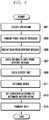
- FIG. 7 is a flowchart showing an operation for transmitting a probe response message by a Wi-Fi device according to an exemplary embodiment of the present invention.
- the Wi-Fi device may correspond to a device (e.g. the reception device 210) operating in an AP mode as described above.
- the Wi-Fi device may receive a probe request message from a particular Wi-Fi device (e.g. the transmission device 100) operating in a non-AP mode (i.e. an STA mode) in step 701.
- the probe request message includes particular service information requested by the Wi-Fi device operating in the non-AP mode.
- the Wi-Fi device may generate a probe response message additionally including support information in step 703.
- the probe response message may include various pieces of conventional information required for a connection to a Wi-Fi service.
- the Wi-Fi device may generate a probe response message which includes the multiple pieces of conventional information and additionally includes manufacturer information and information on functions supported by the device and its capabilities in an OUI field thereof as described above.
- the manufacturer information in the OUI field may indicate that the Wi-Fi device supports a WPS function according to automatic authentication between the Wi-Fi device and another Wi-Fi device which have been manufactured by the same manufacturer.
- the Wi-Fi device may define support information, which indicates whether the Wi-Fi device can support particular service information requested by the probe request message, in the OUI field of the probe response message.
- the Wi-Fi device may transmit the generated probe response message to the counterpart Wi-Fi device (e.g. the transmission device 100) which has transmitted the probe request message in step 705.
- the Wi-Fi device may support a Wi-Fi service after setting a connection to the counterpart Wi-Fi device according to the automation of the WPS function by exchanging an automatic authentication request message and an automatic authentication response message between the Wi-Fi device and the counterpart Wi-Fi device as described above.
- FIG. 8 is a flowchart illustrating an operation of a Wi-Fi device for a Wi-Fi service according to an exemplary embodiment of the present invention.
- a Wi-Fi device may correspond to a device (e.g. the transmission device 100) operating in a non-AP mode (i.e. an STA mode) as described above.
- a non-AP mode i.e. an STA mode
- the control unit 140 may check an OUI field of a beacon message received from each of the other nearby Wi-Fi devices in step 803.
- the control unit 140 may receive a beacon message periodically broadcast by each of the Wi-Fi devices existing around the relevant Wi-Fi device as described above.
- the control unit 140 may check support information defined in an OUI field of each beacon message.
- the control unit 140 may select Wi-Fi devices, which have been manufactured by the same manufacturer as that of the Wi-Fi device including the control unit 140, and may determine a counterpart Wi-Fi device capable of supporting a Wi-Fi service corresponding to the application, the execution of which has been requested, among the selected Wi-Fi devices. For example, it is assumed that a Wi-Fi service corresponding to the execution of the application is the output of video data. In this case, the control unit 140 may select Wi-Fi devices, which have been manufactured by the same manufacturer as that of the Wi-Fi device including the control unit 140, with reference to the OUI field of each beacon message.
- control unit 140 may finally determine a Wi-Fi device having the video data output function among the selected nearby Wi-Fi devices.
- the control unit 140 may determine an optimal counterpart Wi-Fi device based on multiple pieces of signal information of the relevant devices as described above. An exemplary method for determining an optimal counterpart device will be described below.
- the control unit 140 may set a connection to the determined counterpart Wi-Fi device according to automatic authentication between the relevant Wi-Fi device and the determined counterpart Wi-Fi device in step 809.
- the control unit 140 may transmit data corresponding to the executed application to the determined counterpart Wi-Fi device.
- the control unit 140 may transmit, to the determined counterpart Wi-Fi device, an automatic authentication request message including a PIN code or a button input command code necessary to execute a WPS function according to automatic authentication in a PIN scheme or in a PBC scheme, as described above.
- the control unit 140 may set a connection to the determined counterpart Wi-Fi device, and may transmit data to the determined counterpart Wi-Fi device.
- FIG. 9 is a flowchart illustrating an operation of a Wi-Fi device for a Wi-Fi service according to an exemplary embodiment of the present invention.
- a Wi-Fi device may correspond to a device (e.g. the transmission device 100) operating in a non-AP mode (i.e. an STA mode) as described above.
- a non-AP mode i.e. an STA mode
- the control unit 140 may broadcast probe request messages in step 903. For example, when application execution is requested, the control unit 140 may generate and broadcast probe request messages for scanning Wi-Fi devices existing around the relevant Wi-Fi device.
- a probe request message may include a particular service (e.g. request function information on the execution, reproduction, output, storage, etc. of data corresponding to the executed application) requested by a Wi-Fi device (e.g. the transmission device 100) in the non-AP mode, as described above.
- the control unit 140 may receive a probe response message as a response to the transmitted probe request message from each of the nearby Wi-Fi devices.
- a probe response message may include manufacturer information, information on functions supported by the device and its capabilities, support information on requested services, etc. in an OUI field thereof, as described above.
- the control unit 140 may check the OUI field of each probe response message in step 907.
- the control unit 140 may check support information defined in the OUI field of each probe response message. Based on the support information, the control unit 140 may select Wi-Fi devices, which have been manufactured by the same manufacturer as that of the Wi-Fi device including the control unit 140, and may determine a counterpart Wi-Fi device capable of supporting a Wi-Fi service corresponding to the application, the execution of which has been requested, among the selected Wi-Fi devices in step 911. For example, it is assumed that a Wi-Fi service corresponding to the execution of the application is the output of video data.
- control unit 140 may select Wi-Fi devices, which have been manufactured by the same manufacturer as that of the Wi-Fi device including the control unit 140, with reference to the OUI field of each probe response message. Then, the control unit 140 may finally determine a Wi-Fi device having the video data output function among the selected nearby Wi-Fi devices. When there are multiple devices of the same manufacturer, which support the requested service, the control unit 140 may determine an optimal counterpart Wi-Fi device based on the multiple pieces of signal information of the relevant devices as described above. An exemplary method for determining an optimal counterpart device will be described below.
- the control unit 140 may set a connection to the determined counterpart Wi-Fi device according to automatic authentication between the relevant Wi-Fi device and the determined counterpart Wi-Fi device in step 913.
- the control unit 140 may transmit data corresponding to the executed application to the determined counterpart Wi-Fi device.
- the control unit 140 may transmit, to the determined counterpart Wi-Fi device, an automatic authentication request message including a PIN code or a button input command code necessary to execute a WPS function according to automatic authentication in a PIN scheme or in a PBC scheme, as described above.
- the control unit 140 may set a connection to the determined counterpart Wi-Fi device, and may transmit data to the determined counterpart Wi-Fi device.
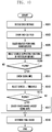
- FIG. 10 is a flowchart showing a control method for determining a counterpart Wi-Fi device, to which a Wi-Fi device is to set a connection, by the Wi-Fi device according to an exemplary embodiment of the present invention.
- a Wi-Fi device may correspond to a device operating in a non-AP mode (i.e. an STA mode).
- FIG. 10 may show an operation for determining a final counterpart Wi-Fi device, to which the transmission device 100 is to set a direct connection among the multiple reception devices 200, as described above.
- the Wi-Fi device operating in a non-AP mode is first assumed to be in a state where the Wi-Fi device has received a message from each of Wi-Fi devices existing around it in step 1001.
- the Wi-Fi device in the non-AP mode may receive a beacon message, which is periodically broadcast by each of the nearby Wi-Fi devices in an AP mode, as described above.
- the Wi-Fi device in the non-AP mode may receive a probe response message as a response to the probe request message, which is transmitted by each of the nearby Wi-Fi devices in an AP mode, as described above.
- the control unit 140 of the Wi-Fi device may check an OUI field of each received message in step 1003.
- the control unit 140 may select devices, which have been manufactured by the same manufacturer as that of the Wi-Fi device including the control unit 140, based on manufacturer information in the OUI field of each received message.
- the control unit 140 may select devices capable of supporting a particular service corresponding to the application, the execution of which has been requested, based on support information in each OUI field among the selected devices of the same manufacturer.
- control unit 140 may determine whether the number of the devices selected in step 1007 is greater than one. For example, the control unit 140 may determine that the number of the first-selected devices of the same manufacturer is greater than one, and may determine that there are multiple devices each of which is secondly selected among the first-selected devices and supports a particular service.
- step 1019 the control unit 140 may determine the relevant device as a final counterpart device.
- the control unit 140 may check signal information of each device in step 1011.
- the signal information may include received signal intensity, a bit-rate, etc.
- the signal information may be obtained by rules for checking signal intensities in Wi-Fi devices.
- signal information e.g. signal intensity and a bit-rate
- each device may be additionally included in a relevant message and the relevant message including the signal information may be transmitted, as described above.
- the control unit 140 may select devices, each of which has signal information having a value (e.g. signal intensity) equal to or greater than a preset threshold among the multiple pieces of signal information of the secondly-selected devices. For example, the control unit 140 may select devices from the secondly-selected devices by checking their received signal intensities and by comparing each of the received signal intensities with the preset threshold.
- a value e.g. signal intensity
- control unit 140 may determine whether there are multiple devices, each of which has been selected in step 1013 and has the signal information having the value (e.g. signal intensity) equal to or greater than the threshold in step 1015. Namely, the control unit 140 may determine whether the number of the thirdly-selected devices is plural by checking the received signal intensities after the first and second selections, as described above.
- step 1019 the control unit 140 may determine the relevant device as a final counterpart device.
- the control unit 140 may select a device having the largest signal information among the multiple pieces of signal information (e.g. received signal intensities) of the thirdly-selected devices in step 1017. For example, the control unit 140 may select a device having the largest received signal intensity.
- control unit 140 may determine the finally-selected device as a final device for setting a connection to a Wi-Fi service.
- the control unit 140 may control an operation of a set scheme. For example, after requesting message retransmission, the control unit 140 may re-perform the above operation based on newly-received messages. Other than this, the control unit 140 enables a user to manually select counterpart devices by outputting an error message and a list of devices collected by message reception.
- the above-described exemplary method for providing a Wi-Fi service by a Wi-Fi device may be implemented in the form of program instructions which can be performed by one or more various computers, and may be stored in a recording medium which can be read by the various computers.
- the recording medium which can be read by the various computers, may separately include program instructions, data files and data structures, or may include combinations of them.
- the program instructions stored in the recording medium may be specially designed and structured ones for exemplary embodiments of the present invention or ones which have been publicly known and can be used to/by those skilled in the computer software arts.
- the recording media readable by the various computers include magnetic media such as a hard disc, a floppy disc and a magnetic tape, optical media such as a Compact Disc Read Only Memory (CD-ROM) and a Digital Versatile Disc (DVD), magnetic-optical media such as a floptical disc, a Read Only Memory (ROM), a Random access Memory (RAM), a flash memory, etc., which correspond to hardware apparatuses specially configured to store and execute the program instructions.
- the program instructions include not only a machine code generated by a compiler but also a high-level language code executable by a computer by using an interpreter, etc.
- the above hardware apparatuses may be configured to operate as at least one software module in order to perform the operation of the present invention, and vice versa.
- exemplary embodiments of the present invention provide a method and a system for providing a Wi-Fi service by a Wi-Fi device, in which Wi-Fi devices can transmit/receive information on their functions and capabilities supported to/from each other and an optimal counterpart Wi-Fi device can be determined among multiple counterpart Wi-Fi devices during automatic connection setting of a WPS function according to automatic authentication between the Wi-Fi devices.
- each of the Wi-Fi devices can recognize the support information on the functions supported by the other Wi-Fi devices. Accordingly, when Wi-Fi devices are interconnected, each Wi-Fi device can automatically authenticate another Wi-Fi device without the intervention of a user.
- an optimal counterpart Wi-Fi device for performing the particular service can be automatically rapidly selected among the multiple Wi-Fi devices. Namely, when a particular application for using a Wi-Fi service is executed, it is possible to rapidly select an appropriate counterpart Wi-Fi device supporting the functions of the particular application, so that the convenience of using the service can be provided. According to exemplary embodiments of the present invention, inconvenient handling actions following a connection between the Wi-Fi devices can be reduced, so that it is possible to contribute to the improvement of the usability, convenience and competitiveness of the Wi-Fi devices.
Description
- The present invention relates to a Wireless Fidelity (Wi-Fi) device. More particularly, the present invention relates to a method and a system in which Wi-Fi devices share support information on functions that they support by transmitting/receiving the support information to/from each other and provide Wi-Fi services based on the shared support information.
- With the development of wireless technology, wired networks that were once used by many people have recently been replaced by wireless networks. Namely, since wireless technology can address the problem of restriction on mobility that a wired network has, research on technologies that use a wireless network has been actively conducted. Also, the propagation and use of various portable terminals have recently rapidly increased due to the remarkable development of information communication technology, semiconductor technology, etc. More particularly, recent portable terminals provide a mobile convergence phase in which they do not stay in a traditional domain but covers domains of other terminals. As an example, a mobile communication terminal has various additional functions, which include a Television (TV) viewing function (e.g. mobile broadcasting such as Digital Multimedia Broadcasting (DMB) or Digital Video Broadcasting (DVB)), a music playback function (e.g. Moving Picture Experts Group Audio Layer-3 (MP-3), a function for taking photos, a Wi-Fi connection function, etc., as well as typical communication functions (e.g. a voice phone call and message transmission/reception).
- A Wireless Local Area Network (WLAN) is also known as "Wireless Fidelity (Wi-Fi)" because a wireless network can be conveniently used, similar to high-fidelity (hi-fi) audio. In the WLAN, the Internet can be accessed through a portable terminal or a notebook computer within a predetermined radius an Access Point (AP). Thus, the WLAN, which has the potential of an open-type wireless network, is being rapidly spread along with the popularization of portable terminals. Currently, Wi-Fi is being used to provide high-speed data services to various locations including schools, airports, hotels, offices, etc.
- However, there is a problem in that a connection function essential for a Wi-Fi service is inconvenient. Accordingly, a portable terminal supporting the Wi-Fi provides a Wi-Fi Protected Setup (WPS) function for simple and easy settings from a wireless connection to a security setting. Namely, each Wi-Fi device currently provides a function capable of setting a secure connection between Wi-Fi devices by pressing a particular button assigned by the WPS function or by directly inputting a given PIN code.
- However, the above WPS function is not widely recognized by general users. Also, the WPS function has the inconvenience of requiring a user to manually press a particular assigned button or manually input multiple digits of a Personal Identification Number (PIN) code. Further, each portable convergence terminal, which has recently been propagated, requires a new process for a Wi-Fi connection in addition to the existing convergence function. Accordingly, inconvenience is caused to users of the portable convergence terminals.
-
US 2004/205246 describes a method for identifying devices in a wireless LAN home network.US 2005/078644 describes a technique for service discovery in a wireless network.US 2009/104875 describes a technique for establishing a communication link between a plurality of networked electronic devices that communicate using a short-range wireless communication protocol. - Aspects of the present invention are to address at least the above-mentioned problems and/or disadvantages and to provide at least the advantages described below. Accordingly, an aspect of the present invention is to provide a method and a system in which Wireless Fidelity (Wi-Fi) devices can exchange information with each other regarding functions that they support.
- Another aspect of the present invention is to provide a control method by which a Wi-Fi device can select an optimal counterpart Wi-Fi device supporting functions of a Wi-Fi service-based application when the Wi-Fi device executes the Wi-Fi service-based application.
- Another aspect of the present invention is to provide a method and a system in which a Wi-Fi device can provide services by rapidly selecting and setting a connection to an optimal counterpart Wi-Fi device for operating a Wi-Fi service-based application based on support information provided by other Wi-Fi devices.
- Another aspect of the present invention is to provide a method and a system capable of selecting an optimal counterpart Wi-Fi device from multiple counterpart Wi-Fi devices by checking the received signal intensities of the multiple counterpart Wi-Fi devices during automatic connection setting of a Wi-Fi Protected Setup (WPS) function according to automatic authentication between the Wi-Fi devices.
- Another aspect of the present invention is to provide a method and a system that can implement an optimal Wi-Fi service environment capable of providing the user convenience of using a Wi-Fi service by enabling Wi-Fi devices to share information supported by themselves with each other.
- Another aspect of the present invention is to provide a method and a system that improve the usability and convenience of a Wi-Fi device by automatically selecting an optimal counterpart Wi-Fi device capable of using a particular Wi-Fi based service.
- In accordance with an aspect of the present invention, there is provided a method, performed by a Wireless Fidelity, Wi-Fi, electronic device, for providing a Wi-Fi service according to the disclosure of the appended
claim 1. - In accordance with another aspect of the present invention, there is provided an electronic device for providing a Wireless Fidelity, Wi-Fi, service according to the disclosure of the appended
claim 6. - Other aspects, advantages, and salient features of the invention will become apparent to those skilled in the art from the following detailed description, which, taken in conjunction with the annexed drawings, discloses exemplary embodiments of the invention. Nevertheless the invention is disclosed uniquely by the the appended set of claims. The embodiments and/or examples of the following description which are not covered by the appended claims are considered as not being part of the present invention.
- The above and other aspects, features, and advantages of certain exemplary embodiments of the present invention will be more apparent from the following description taken in conjunction with the accompanying drawings, in which:
-
FIG. 1 is a schematic view illustrating the configuration of a system for describing an operation according to an exemplary embodiment of the present invention; -
FIG. 2 is a block diagram schematically illustrating a configuration of a Wireless Fidelity (Wi-Fi) device according to an exemplary embodiment of the present invention; -
FIG. 3 is an illustrative view showing a message format used to transmit support information of another Wi-Fi device according to an exemplary embodiment of the present invention; -
FIG. 4 is a signal flow diagram illustrating an operation for a Wi-Fi based service between Wi-Fi devices according to an exemplary embodiment of the present invention; -
FIG. 5 is a signal flow diagram illustrating an operation for a Wi-Fi based service between Wi-Fi devices according to an exemplary embodiment of the present invention; -
FIG. 6 is a flowchart showing an operation for transmitting a beacon message by a Wi-Fi device according to an exemplary embodiment of the present invention; -
FIG. 7 is a flowchart showing an operation for transmitting a probe response message by a Wi-Fi device according to an exemplary embodiment of the present invention; -
FIG. 8 is a flowchart illustrating an operation of a Wi-Fi device for a Wi-Fi service according to an exemplary embodiment of the present invention; -
FIG. 9 is a flowchart illustrating an operation of a Wi-Fi device for a Wi-Fi service according to an exemplary embodiment of the present invention; -
FIG. 10 is a flowchart showing a control method for determining a counterpart Wi-Fi device, to which a Wi-Fi device is to set a connection, by the Wi-Fi device according to an exemplary embodiment of the present invention; and -
FIGs. 11A and11B are an illustrative view showing an information table according to an exemplary embodiment of the present invention. - Throughout the drawings, it should be noted that like reference numbers are used to depict the same or similar elements, features, and structures.
- The following description with reference to the accompanying drawings is provided to assist in a comprehensive understanding of exemplary embodiments of the invention as defined by the claims. It includes various specific details to assist in that understanding but these are to be regarded as merely exemplary. Accordingly, those of ordinary skill in the art will recognize that various changes and modifications of the embodiments described herein can be made without departing from the scope of the invention. In addition, descriptions of well-known functions and constructions may be omitted for clarity and conciseness.
- The terms and words used in the following description and claims are not limited to the bibliographical meanings, but, are merely used by the inventor to enable a clear and consistent understanding of the invention. Accordingly, it should be apparent to those skilled in the art that the following description of exemplary embodiments of the present invention is provided for illustration purpose only and not for the purpose of limiting the invention as defined by the appended claims.
- It is to be understood that the singular forms "a," "an," and "the" include plural referents unless the context clearly dictates otherwise. Thus, for example, reference to "a component surface" includes reference to one or more of such surfaces.
- The following disclosure relates to a technology for automatic authentication between Wireless Fidelity (Wi-Fi) devices. According to an exemplary embodiment of the present invention, a Wi-Fi Protected Setup (WPS) function for simple and easy settings from a wireless connection to a security setting can be extended without a complicated setting process in a Wi-Fi device. Namely, a user can set a connection between Wi-Fi devices by pressing a particular button assigned to a Wi-Fi device or by inputting a given Personal Identification Number (PIN) code through the Wi-Fi device in order to use a WPS function. Moreover, exemplary embodiments of the present invention enable automatic authentication without the intervention of a user when the use of a WPS function is desired. To this end, in an exemplary implementation, Wi-Fi devices can transmit information to each other regarding functions that they support, so that each of the Wi-Fi devices can recognize the information regarding functions supported by a counterpart Wi-Fi device. Also, exemplary embodiments of the present disclosure propose an apparatus and a control method, in which a Wi-Fi device can determine an optimal counterpart Wi-Fi device among multiple counterpart Wi-Fi devices during automatic connection setting of the WPS function according to automatic authentication between the Wi-Fi devices based on the support information. Therefore, an exemplary apparatus and control method proposed by the present disclosure can more simply and easily support a Wi-Fi service.
- Hereinafter, an exemplary configuration of a Wi-Fi device and a method for controlling the operation thereof will be described with reference to
FIGs. 1 to 11B . However, it should be noted that the configuration of a Wi-Fi device and a method for controlling the operation thereof are not limited to the following description and can be applied to various embodiments based on the following description. -
FIG. 1 is a schematic view illustrating the configuration of a system for describing an operation according to an exemplary embodiment of the present invention. - Referring to
FIG. 1 , a system of the present invention includes a Wi-Fi device (hereinafter, referred to as a "transmission device") 100 functioning as a transmitter, and a Wi-Fi device (hereinafter, referred to as a "reception device") 200 functioning as a receiver. In this specification, a transmission device and a reception device are discriminated from each other for convenience of description. Further, in the present invention, thereception device 200 may represent multiple Wi-Fi devices. For example, thereception device 200 may be any of various electronic apparatuses including a music playback player, a display apparatus, a portable game terminal, a printer, etc, each of which includes a built-in Wi-Fi module. In the following description, thereception device 200 will be described as any one or multiple ones among the various electronic apparatuses as described above. Of course, it is to be understood that thetransmission device 100 may also include any of various electronic apparatuses including a music playback player, a display apparatus, a portable game terminal, a printer, etc, each of which includes a built-in Wi-Fi module. For ease of description, thetransmission device 100 is illustrated inFIG. 1 as a mobile communication terminal. - As illustrated in
FIG. 1 , the Wi-Fi based system may support a Wi-Fi direct function between thetransmission device 100 and thereception device 200, and thetransmission device 100 and thereception device 200 may be directly interconnected in a Direct Access (DA) mode. Namely,FIG. 1 illustrates the relation of setting a connection between the Wi-Fi devices Fi devices - Also, the Wi-
Fi devices transmission device 100, thetransmission device 100 identifies support information transmitted from thereception device 200. Then, as an example, thetransmission device 100 can first select reception devices, which have been manufactured by the same manufacturer as that of thetransmission device 100, with reference to the identified support information. When the number of reception devices selected by the first selection is greater than one, thetransmission device 100 may secondly select reception devices capable of supporting a Wi-Fi service according to the executed application among the multiple first-selected reception devices. Further, when the number of the secondly-selected reception devices is also greater than one, thetransmission device 100 may determine an optimal reception device for the Wi-Fi service among the multiple secondly-selected reception devices by checking multiple pieces of signal information (e.g. received signal intensities) from the secondly-selected reception devices. Then, data related to the executed application is transmitted to the determined reception device, so that the application may be executed in the determined reception device. An exemplary method for transmitting support information and determining a final counterpart device as described above, and a control method thereof, which is related to the above method, will be described with reference to the drawings described below. - Meanwhile,
FIG. 1 illustrates the configuration of the system in which the Wi-Fi devices Fi devices Fi devices Fi devices - For example, the Wi-
Fi devices Fi devices Fi devices Fi devices -
FIG. 2 is a block diagram schematically illustrating a configuration of a Wi-Fi device according to an exemplary embodiment of the present invention. The configuration of a Wi-Fi device as illustrated inFIG. 2 may be commonly applied to both thetransmission device 100 and thereception device 200 as described above with reference toFIG. 1 . - Referring to
FIG. 2 , a Wi-Fi device includes a Wi-Fi module 110, aninput unit 120, astorage unit 130, and acontrol unit 140. Also, the Wi-Fi device may include various configurations, depending on the form thereof. For example, the Wi-Fi device may further include a display unit for displaying screen data, a Radio Frequency (RF) module for performing a mobile communication function, an audio processor having a microphone (MIC) and a speaker (SPK), a camera module for capturing still or moving images, a digital broadcasting module for receiving and reproducing digital broadcasting (e.g. mobile broadcasting such as Digital Multimedia Broadcasting (DMB) or Digital Video Broadcasting (DVB)), and a Bluetooth communication module for performing a Bluetooth communication function. However, the description and illustration of the above elements will be omitted. - The above Wi-
Fi module 110 supports Internet Protocol (IP)-based mobile communication of the Wi-Fi device. In an exemplary embodiment, the Wi-Fi module 110 includes anAP module 113 and a station (STA)module 115. Under the control of thecontrol unit 140, the Wi-Fi module 110 may operate in an AP mode by waking theAP module 113 or may operate in a non-AP mode (i.e. an STA mode) by waking theSTA module 115. In this specification, the non-AP mode (i.e. the STA mode) refers to a mode in which a Wi-Fi device operates depending on the function of a device side when providing a Wi-Fi based service. For example, the non-AP mode may refer to a mode in which a Wi-Fi device operates as thetransmission device 100 as described above with reference toFIG. 1 . Also, in this specification, the AP mode refers to a mode in which the Wi-Fi device operates depending on the function of an AP side when providing the Wi-Fi based service. For example, the AP mode may refer to a mode in which a Wi-Fi device operates as thereception device 200 as described above with reference toFIG. 1 . In this specification, the AP mode and the non-AP mode (i.e. the STA) are classified for convenience of description. - The Wi-
Fi module 110 transmits support information regarding functions supported by the Wi-Fi device according to the control of thecontroller 140 in the AP mode of the Wi-Fi device. For example, the Wi-Fi module 110 may periodically broadcast a beacon message, which includes the support information of the Wi-Fi device, through theAP module 113 in the AP mode. Otherwise, in the AP mode, the Wi-Fi module 110 may receive a request message (e.g. a probe request message) from another Wi-Fi device (e.g. thetransmission device 100 illustrated inFIG. 1 ) which operates in the non-AP mode, and then provide the received request message to thecontrol unit 140. In response, the Wi-Fi module 110 may transmit a message (e.g. a probe response message), which includes the support information of the Wi-Fi device and is provided by thecontrol unit 140, through theAP module 113. - Also, the Wi-
Fi module 110 may transmit a probe request message as described above to another Wi-Fi device (e.g. thereception device 200 illustrated inFIG. 1 ), which operates in the AP mode, through theSTA module 115 in the non-AP mode of the Wi-Fi device. Then, the Wi-Fi module 110 may receive a beacon message or a probe response message as described above, which includes support information of another Wi-Fi device operating in the AP mode and is transmitted from the other Wi-Fi device, through theSTA module 115, and provide the received beacon message or probe response message to thecontrol unit 140. Next, the Wi-Fi module 120 may transmit/receive an automatic authentication request message and an automatic authentication response message as described below. - The transmission and reception of the messages as described above, which include a beacon message, a probe request message, a probe response message, an automatic authentication request message, and an automatic authentication response message, will be described in more detail in the following discussion regarding a method for operation control.
- The
input unit 120 detects a handling action of a user and generates an input signal corresponding to the detected handling action. Theinput unit 120 provides the generated input signal to thecontrol unit 140. Theinput unit 120 may include multiple buttons. More particularly, theinput unit 120 may include at least one button for generating a user input signal related to the execution (e.g. performing a WPS function for setting a connection between Wi-Fi devices) of a Wi-Fi function for using a Wi-Fi based service. - The
storage unit 130 stores various programs and data executed and processed by the Wi-Fi device. It may include at least one volatile memory device and at least one nonvolatile memory device. For example, thestorage unit 130 may continually or temporarily store an operating system of the Wi-Fi device, programs and data related to a control operation for an AP mode by the Wi-Fi module 110, programs and data related to a control operation for a non-AP mode (i.e. an STA mode) by the Wi-Fi module 110, programs and data related to a control operation for an automatic authentication function in the Wi-Fi device, programs and data related to a control operation for the transmission function of support information of the Wi-Fi device, programs and data related to a control operation for the function of determining an optimal counterpart Wi-Fi device by using signal information (e.g. a received signal intensity), etc. Thestorage unit 130 may store a threshold for determining an optimal counterpart Wi-Fi device. Also, thestorage unit 130 may store an information table for providing the support information of the Wi-Fi device. In this specification, the information table may be constructed as illustrated inFIGs. 11A and11B . -
FIGs. 11A and11B are an illustrative view showing an information table according to an exemplary embodiment of the present invention. - Referring to
FIGs. 11A and11B , the information table includes a category field indicating a device type (e.g. Telephone, Computer, Printers, etc.) to which a Wi-Fi device belongs, an Identifier (ID) value field indicating an identifier (e.g. 10) for identifying a relevant Category (e.g. Telephone), a Sub-category field indicating information (i.e. a convergence function, capability, Windows Mobile, Phone-single mode, Phone-dual mode, etc.) supported by a device belonging to the relevant Category (e.g. Telephone), an ID value field indicating an identifier (e.g. 1, 2 or 3) for identifying each piece of information supported by a relevant Sub-category, etc. Also, the information table may include a single category (e.g. Telephone) among the Category items as described above depending on the type of a Wi-Fi device, and may include an ID value for the Category, and sub-categories and ID values for the Sub-categories. For example, when the type of the Wi-Fi device corresponds to "Telephone," the information table may be constructed as illustrated in Table 1 below for the category "Telephone" among the illustrations shown inFIGs. 11A and11B . Also, the information table includes information on Sub-categories which may change depending on functions supported by the relevant Wi-Fi device in Table 1 below.Table 1 Category ID value Sub-category ID value Telephone 10 Windows mobile 1 Phone- single mode 2 Phone- dual mode 3 Smartphone- single mode 4 Smartphone- dual mode 5 - The
control unit 140 controls overall operations of the Wi-Fi device. Thecontrol unit 140 may control an operation related to functions for providing a Wi-Fi based service of the Wi-Fi device. Also, thecontrol unit 140 may control an operation related to the automation of a WPS function of the Wi-Fi device. For example, thecontrol unit 140 may control the automation of the WPS function through an automatic authentication function in the Wi-Fi device. In an exemplary implementation, thecontrol unit 140 may control operation of the Wi-Fi module 110 by set periods. For example, thecontrol unit 140 may wake theAP module 113 of the Wi-Fi module 110 or may wake theSTA module 115 of the Wi-Fi module 110 by the set periods. - Also, the
control unit 140 may control an operation related to the AP mode and the non-AP mode (i.e. the STA mode) of the Wi-Fi device according to an operating scheme of the Wi-Fi module 110. For example, when the Wi-Fi device operates in the AP mode and periodically broadcasts a beacon message at beacon intervals, thecontrol unit 140 may include manufacturer information of the Wi-Fi device and support information on functions and capability supported by the Wi-Fi device in the beacon message, and may transmit the beacon message including them. Also, when the Wi-Fi device operates in the AP mode and receives a probe request message from a counterpart Wi-Fi device operating in the non-AP mode (i.e. the STA mode), thecontrol unit 140 may include manufacturer information of the Wi-Fi device and support information on functions and capability supported by the Wi-Fi device in a probe response message corresponding to the received probe request message, and may transmit the probe response message including them to the counterpart Wi-Fi device. - Also, when the Wi-Fi device operates in the non-AP mode (i.e. the STA mode) and receives a beacon message or a probe response message from a counterpart Wi-Fi device operating in the AP mode, the
control unit 140 may check support information included in the relevant beacon message or probe response message, and may confirm functions and capability supported by the counterpart Wi-Fi device. More particularly, when the Wi-Fi device executes an application according to the Wi-Fi based service, thecontrol unit 140 may determine an optimal counterpart Wi-Fi device for the Wi-Fi based service corresponding to the executed application based on the support information obtained from the counterpart Wi-Fi device as described above. For example, thecontrol unit 140 may first select reception devices of the same manufacturer based on the support information of the beacon messages or probe response messages. When the number of the first-selected reception devices is greater than one, thecontrol unit 140 may secondly select reception devices capable of supporting the particular requested service among the multiple first-selected reception devices. When the number of the secondly-selected reception devices is greater than one, thecontrol unit 140 may determine a final counterpart Wi-Fi device for the Wi-Fi service among the multiple secondly-selected reception devices by checking multiple pieces of signal information (e.g. received signal intensities) from the secondly-selected reception devices. - The
control unit 140 may control operating of the Wi-Fi based service according to the determined counterpart Wi-Fi device and the executed application. For example, when an application related to video data reproduction is executed, thecontrol unit 140 may determine a counterpart Wi-Fi device having a video data output function, by checking the obtained support information. Thereafter, thecontrol unit 140 transmits the video data to the determined counterpart Wi-Fi device, so that the determined counterpart Wi-Fi device can output the received video data. - When the counterpart Wi-Fi device has been determined, the
control unit 140 may control connection setting according to the transmission/reception of an automatic authentication request message and an automatic authentication response message as described below. For example, when the Wi-Fi device operates in the non-AP mode, thecontrol unit 140 may control transmitting of the automatic authentication request message, which includes a PIN code or a button input command code, to a counterpart Wi-Fi device in a scheme defined for a WPS function. Also, when the Wi-Fi device operates in the AP mode and receives an automatic authentication request message, thecontrol unit 140 may automatically input the PIN code for the WPS function or may activate the button input for the WPS function according to the PIN code or the button input command code included in the received automatic authentication request message, and may control the transmission of an automatic authentication response message. As described above, Wi-Fi devices of the same manufacturer may mutually transmit/receive an automatic authentication request message and an automatic authentication response message based on support information defined in a beacon message or a probe response message. Namely, it is possible to set a connection between the Wi-Fi devices according to the automation of the WPS function according to automatic authentication by the transmission/reception of the messages between the Wi-Fi devices of the same manufacturer based on the support information. - The
control unit 140 will be described in more detail regarding a method for operation control as described below. Thecontrol unit 140 also performs various control operations related to typical functions of the Wi-Fi device. For example, when a communication function using a mobile communication network is executed in the Wi-Fi device, thecontrol unit 140 may control operating of the communication function according to the execution of the application. Also, when an application of a communication function using a local network is executed in the Wi-Fi device, thecontrol unit 140 may control operating of the communication function according to the execution of the application. - Meanwhile, the Wi-Fi devices illustrated in
FIGs. 1 and2 may include all types of information communication apparatuses, all types of multimedia apparatuses, and application apparatuses for all types of information communication apparatuses and all types of multimedia apparatuses. For example, the Wi-Fi device may include small devices, such as a mobile communication terminal, a smart phone, a Portable Multimedia Player (PMP), a digital broadcasting player, a Personal Digital Assistant (PDA), a music player (e.g. an MP3 player), and a portable game terminal, which operate by communication protocols corresponding to various communication systems. Also, the Wi-Fi device may be operated as a medium or large device, such as a Television (TV), a Large Format Display (LFD), a Digital Signage (DS), a media pole, a Personal Computer (PC), a notebook, a printer, and a combination apparatus. -
FIG. 3 is an illustrative view showing a message format used to transmit support information of another Wi-Fi device according to an exemplary embodiment of the present invention. - Referring to
FIG. 3 , each of a beacon message and a probe response message as described above includes an Organizationally Unique Identifier (OUI)field 301, a Len (Length)field 303, an ID (Identifier)field 305, aVersion field 307, aType field 309, aValue field 311, and a ServiceProtocol Type field 313. The format of a probe response message will be illustratively described with reference toFIG. 3 . - The
OUI field 301 represents a service information field for defining service support information. TheOUI field 301 may have a value indicating manufacturer information of a Wi-Fi device. For example, theOUI field 301 may have a value of "00 00 F0" for Samsung Electronics Co., Ltd. TheOUI field 301 has a unique value assigned to each manufacturer. In an exemplary implementation, theOUI field 301 may include not only the manufacturer information as described above but also support information on functions and capability supported by the Wi-Fi device. Also, in theOUI field 301, support information on particular service information requested by a particular Wi-Fi device may be additionally defined. TheOUI field 301 may be used to indicate that the relevant Wi-Fi device supports a WPS function according to automatic authentication, which is employed by Wi-Fi devices of the same manufacturer, and to enable the Wi-Fi devices to recognize the functions supportable by the Wi-Fi devices. An exemplary operation for transmitting/receiving a message including theOUI field 301 will be described below. - The
Len field 303 represents a field for recording the entire size of a beacon message or a probe response message. TheID field 305 is used to prevent the duplication of the value of theOUI field 301 as described above, and represents a field of a state where a particular value is not determined. TheVersion field 307 represents a field for extension, and may be a field defined depending on the form change of a message used in a Wi-Fi based system. TheType field 309 represents a field for defining the type of a beacon message or a response message. TheType field 309 may be defined to indicate "resolved" for "0000," "advertise" for "0001," "WPS start request" for "0010," and "WPS response" for "0011." - The
Value field 311 represents a field for defining a value for a Category of a Wi-Fi device and values for Sub-categories supported within the relevant Category based on the information table as described above. Namely, theValue field 311 is used to define an apparatus Category and Sub-categories of the Wi-Fi device. Therefore, theValue field 311 may have a value indicating which Category the relevant Wi-Fi device belongs to, and may have values indicating information on particular functions and capability supported by the relevant Wi-Fi device. For example, theValue field 311 may have a value indicating that the Wi-Fi device belongs to Audio Devices and values indicating a particular function and capability among the Audio Devices. Each value defined in theValue field 311 may be defined by previously classifying devices according to Categories as described with reference to Table 1. - The Service
Protocol Type field 313 is used to define the protocol type of a wireless environment for transmitting/receiving a probe response message. The ServiceProtocol Type field 313, for example, may be defined to indicate "all service protocol types" for "00000000," "bonjour" for "00000001," "UPnP" for "00000010," "ws-discovery" for "00000011," and "vendor specific" for "11111111." Also, a value, which is still not defined in the ServiceProtocol Type field 313, has a state of "reserved." - A message (e.g. a beacon message or a probe response message) defined in an exemplary embodiment of the present invention may indicate which manufacturer has made a Wi-Fi device in the
OUI field 301 as described above. Also, theOUI field 301 or theValue field 311 may be used to indicate which functions and capability are supported by the Wi-Fi device. An exemplary method for using these messages will be described below. - Scan processes among Wi-Fi devices are classified into two types. The first scan process is a passive scan method. The passive scan method corresponds to a method for using a beacon message transmitted by a Wi-Fi device operating in an AP mode. The beacon message indicates a value transmitted by the Wi-Fi device in the AP mode. The beacon message makes it possible to periodically broadcast the existence and support capability (e.g. a signal intensity and a usable bit-rate) of the Wi-Fi device in the AP mode to nearby Wi-Fi devices. According to the passive scan method, a Wi-Fi device operating in a non-AP mode (i.e. an STA mode) may obtain various pieces of information necessary to connect to a network through the candidate Wi-Fi devices, and/or service type information and capability information provided by the candidate Wi-Fi devices, etc., along with a list of the candidate Wi-Fi devices transmitting beacon messages.
- The second scan process is an active scan method. In the active scan method, a Wi-Fi device in the non-AP mode requiring connection setting first transmits a probe request message to a counterpart Wi-Fi device in an AP mode. The probe request message may include particular service information requested by the Wi-Fi device in the non-AP mode. The Wi-Fi device in the AP mode, which has received the probe request message, transmits a probe response message as a response to the probe request message to the Wi-Fi device in the non-AP mode. The probe response message may include various pieces of information necessary for a direct Wi-Fi connection. Accordingly, the Wi-Fi device in the non-AP mode may obtain a list of candidate Wi-Fi devices through the received probe response message.
- Hereinafter, an exemplary operation in a passive scan scheme and an exemplary operation in an active scan scheme will be separately described with reference to
FIG. 4 andFIG. 5 . -
FIG. 4 is a signal flow diagram illustrating an operation for a Wi-Fi based service between Wi-Fi devices according to an exemplary embodiment of the present invention. - In
FIG. 4 , thetransmission device 100 corresponds to a Wi-Fi device operating in the non-AP mode (i.e. the STA mode) and thereception devices 200 correspond to multiple Wi-Fi devices operating in the AP mode, as described above. - Referring to
FIG. 4 , thetransmission device 100 may receive as input the execution of a Wi-Fi based application instep 401. Then, thetransmission device 100 may receive a beacon message which is periodically transmitted by each of thereception devices 200 existing around thetransmission device 100 instep 403. Each of thereception devices 200 may periodically broadcast a beacon message. Accordingly, thetransmission device 100 may receive each beacon message before or after executing an application instep 401. Namely, each beacon message may be periodically broadcast by the Wi-Fi device in the AP mode as described above, so that the Wi-Fi device in the non-AP mode may periodically receive each beacon message in response. - Meanwhile, each of the
reception devices 200 may include manufacturer information and information on functions that they support and on their capabilities in an OUI field of the beacon message, and may transmit the beacon message. For example, on the assumption that, among thereception devices 200,reception devices reception device 250 is a typical Wi-Fi device, each of thereception devices typical reception device 250 may transmit a usual beacon message following a standard protocol. Then, each of thereception devices 200 may define a category and sub-categories of the relevant reception device in a Value field of the beacon message, and may transmit the beacon message including them. - When receiving the beacon message from each of the
reception devices 200 existing around thetransmission device 100, thetransmission device 100 may check the OUI field of each beacon message instep 405. Then, thetransmission device 100 may determine reception devices (e.g. thereception devices 210 and 230), each of which has the same manufacturer information as thetransmission device 100 and supports a service corresponding to the executed application, with reference to the support information defined in the OUI field of each beacon message as described above instep 407. For example, thetransmission device 100 may select counterpart devices, which have been manufactured by the same manufacturer as that of thetransmission device 100, with reference to the OUI field of each received beacon message, and may select a counterpart device supporting a requested service among the selected counterpart devices. When there are multiple counterpart devices (e.g. thereception devices 210 and 230) of the same manufacturer, which support the requested service, thetransmission device 100 may check two pieces of signal information (e.g. received signal intensities) of therelevant reception devices transmission device 100 may select a reception device having signal information which has a value (e.g. signal intensity) equal to or greater than a threshold. When the number of counterpart devices, each of which has signal information having a value equal to or greater than the threshold, is also greater than one, thetransmission device 100 may determine a counterpart device having the largest value in the signal information as a final counterpart device. The determination of a final counterpart device will be described in an exemplary method for operation control below. The case where the determined final counterpart device is thereception device 210 will be illustratively described below. - When the
reception device 210 has been determined as the final counterpart device, thetransmission device 100 transmits an automatic authentication request message for setting a Wi-Fi connection to thedetermined reception device 210 instep 409. In this specification, the automatic authentication request message refers to a message for requesting automatic connection setting according to automatic authentication by a standard previously and mutually agreed upon by devices of the same manufacturer based on information defined in an OUI field. The automatic authentication request message may include a PIN code or a button input command code for wireless encryption setting in a PIN scheme or in a Push Button Configuration (PBC) scheme. - When receiving the automatic authentication request message, the
reception device 210 transmits an automatic authentication response message as a response to the received automatic authentication request message to thetransmission device 100 instep 411. For example, when receiving the automatic authentication request message, thereception device 210 may set connection to thetransmission device 100 in response to an automatic input using a PIN code included in the automatic authentication request message in the PIN scheme, and may transmit an automatic authentication response message as a response to the received automatic authentication request message to thetransmission device 100. Other than this, when receiving the automatic authentication request message, thereception device 210 may set a connection to thetransmission device 100 by automatically activating a button corresponding to a WPS function by a button input command code included in the received automatic authentication request message in the PBC scheme, and may transmit an automatic authentication response message as a response to the received automatic authentication request message to thetransmission device 100. - The
transmission device 100 and thereception device 210 may establish a communication channel for Wi-Fi communication by transmitting/receiving the automatic authentication request message and the automatic authentication response message as described above, and may complete interconnection setting instep 413. - When the
transmission device 100 and thereception device 210 are interconnected, thetransmission device 100 may transmit data, which corresponds to the application executed instep 401, to thereception device 210 instep 415. For example, it is assumed that thetransmission device 100 requests video data reproduction and thereception device 210 is a display apparatus capable of outputting screen data. In this case where thetransmission device 100 and thereception device 210 are interconnected by the automatic authentication therebetween as described above, thetransmission device 100 may transmit the video data to thereception device 210 through the established communication channel. When receiving the video data, thereception device 210 may display the received video data through a display unit thereof. -
FIG. 5 is a signal flow diagram illustrating an operation for a Wi-Fi based service between Wi-Fi devices according to an exemplary embodiment of the present invention. - In
FIG. 5 , thetransmission device 100 corresponds to a Wi-Fi device operating in the non-AP mode (i.e. the STA mode) and thereception devices 200 correspond to multiple Wi-Fi devices operating in the AP mode, as described above. - Referring to
FIG. 5 , thetransmission device 100 may receive as input the execution of a Wi-Fi based application instep 501. Then, thetransmission device 100 broadcasts probe request messages in order to scan Wi-Fi devices existing around thetransmission device 100 instep 503. A probe request message may include a particular service (e.g. request function information on the execution, reproduction, output, storage, etc. of data corresponding to the executed application) requested by a Wi-Fi device (e.g. the transmission device 100) in the non-AP mode. - When receiving the probe request message, each of the
reception devices 200 transmits a probe response message as a response to the received probe request message to thetransmission device 100 instep 505. At this time, each of thereception devices 200 may include manufacturer information, information on functions that they support, information on their capabilities, and support information on requested services in an OUI field of the probe response message, and may transmit the probe response message. For example, on the assumption that, among thereception devices 200, areception device 210 is a Wi-Fi device according to an exemplary embodiment of the present invention whilereception devices reception device 210 may define the above information in the OUI field of the probe response message, and may transmit the probe response message including the above information. On the other hand, each of thetypical reception devices reception devices 200 may define a Category and Sub-categories of the relevant reception device in a Value field of the probe response message, and may transmit the probe response message. - When receiving the probe response message from each of the
reception devices 200 existing around thetransmission device 100, thetransmission device 100 may check the OUI field of each probe response message instep 507. Then, thetransmission device 100 may determine a reception device (e.g. the reception device 210), each of which has the same manufacturer information as thetransmission device 100 and supports a service corresponding to the executed application, with reference to the support information defined in the OUI field of each probe response message as described above instep 509. - Meanwhile, when there are multiple reception devices (e.g. the
reception devices 210 and 230) of the same manufacturer, which support the requested service, thetransmission device 100 may check two pieces of signal information (e.g. received signal intensities) of therelevant reception devices transmission device 100 may select a reception device which has signal information having a value (e.g. signal intensity) equal to or greater than a preset threshold. When there are also a multiple number of reception devices, each of which has signal information having a value equal to or greater than the preset threshold, thetransmission device 100 may determine a reception device having the largest value in the signal information as a final counterpart device (e.g. the reception device 210). The determination of a final counterpart device will be described in an exemplary method for operation control below. - When the
reception device 210 has been determined as the final counterpart device, thetransmission device 100 transmits an automatic authentication request message for setting a Wi-Fi connection to thedetermined reception device 210 instep 511. In this description, the automatic authentication request message refers to a message for requesting automatic connection setting according to automatic authentication by a standard previously and mutually agreed upon by devices of the same manufacturer based on information defined in an OUI field, as described above. The automatic authentication request message may include a PIN code or a button input command code for wireless encryption setting in a PIN scheme or in a PBC scheme. - When receiving the automatic authentication request message, the
reception device 210 transmits an automatic authentication response message as a response to the received automatic authentication request message to thetransmission device 100 instep 513. For example, when receiving the automatic authentication request message, thereception device 210 may set a connection to thetransmission device 100 in response to an automatic input using a PIN code included in the automatic authentication request message in the PIN scheme, and may transmit an automatic authentication response message as a response to the received automatic authentication request message to thetransmission device 100. Other than this, when receiving the automatic authentication request message, thereception device 210 may set a connection to thetransmission device 100 by automatically activating a button corresponding to a WPS function according to a button input command code included in the received automatic authentication request message in the PBC scheme, and may transmit an automatic authentication response message as a response to the received automatic authentication request message to thetransmission device 100. - Then, the
transmission device 100 and thereception device 210 may establish a communication channel for Wi-Fi communication by transmitting/receiving the automatic authentication request message and the automatic authentication response message as described above, and may complete interconnection setting instep 515. - When the
transmission device 100 and thereception device 210 are interconnected, thetransmission device 100 may transmit data, which corresponds to the application executed instep 501, to thereception device 210 instep 517. For example, it is assumed that thetransmission device 100 requests video data reproduction and thereception device 210 is a display apparatus capable of outputting screen data. In this case where thetransmission device 100 and thereception device 210 are interconnected by the automatic authentication therebetween as described above, thetransmission device 100 may transmit the video data to thereception device 210 through the established communication channel. When receiving the video data, thereception device 210 may display the received video data through a display unit thereof. -
FIG. 6 is a flowchart showing an operation for transmitting a beacon message by a Wi-Fi device according to an exemplary embodiment of the present invention. InFIG. 6 , a Wi-Fi device may correspond to a device (e.g. the reception device 210) operating in an AP mode as described above. - Referring to
FIG. 6 , when a time interval becomes a transmission period for a beacon message instep 601, the Wi-Fi device may drive theAP module 113 of the Wi-Fi module 110, and may wake the AP mode instep 603. In this case, the beacon message represents a value transmitted by the Wi-Fi device in the AP mode. The beacon message refers to a message used to periodically broadcast the existence and support capability (e.g. signal intensity, usable bit-rate, etc.) of the Wi-Fi device in the AP mode to other nearby Wi-Fi devices. When receiving the beacon message, each of other nearby Wi-Fi devices enables the Wi-Fi device in the AP mode to be synchronized with the time and to operate in a power saving mode by using the received beacon message. Accordingly, the beacon message may be periodically broadcast at beacon intervals each of which represents a time interval for transmitting a beacon message by the Wi-Fi device in the AP mode. - In
step 605, the Wi-Fi device may generate a beacon message which includes the multiple pieces of information as described above and additionally includes support information. For example, the Wi-Fi device may add manufacturer information and information on functions it supports and its capability to an OUI field of a beacon message as described above, and may generate the beacon message. According to an exemplary implementation, the manufacturer information in the OUI field may indicate that the Wi-Fi device supports a WPS function according to automatic authentication between the Wi-Fi device and another Wi-Fi device which have been manufactured by the same manufacturer. - In
step 607, the Wi-Fi device may transmit the generated beacon message to the nearby Wi-Fi devices. In this case, the beacon message may be periodically transmitted at beacon intervals as described above. Next, the Wi-Fi device may support a Wi-Fi service after setting a connection to a particular counterpart Wi-Fi device according to the automation of the WPS function by exchanging an automatic authentication request message and an automatic authentication response message between the Wi-Fi device and the particular counterpart Wi-Fi device as described above. -
FIG. 7 is a flowchart showing an operation for transmitting a probe response message by a Wi-Fi device according to an exemplary embodiment of the present invention. InFIG. 7 , the Wi-Fi device may correspond to a device (e.g. the reception device 210) operating in an AP mode as described above. - Referring to
FIG. 7 , the Wi-Fi device may receive a probe request message from a particular Wi-Fi device (e.g. the transmission device 100) operating in a non-AP mode (i.e. an STA mode) instep 701. The probe request message includes particular service information requested by the Wi-Fi device operating in the non-AP mode. - When receiving the probe request message, the Wi-Fi device may generate a probe response message additionally including support information in
step 703. The probe response message may include various pieces of conventional information required for a connection to a Wi-Fi service. Also, the Wi-Fi device may generate a probe response message which includes the multiple pieces of conventional information and additionally includes manufacturer information and information on functions supported by the device and its capabilities in an OUI field thereof as described above. According to an exemplary embodiment of the present invention, the manufacturer information in the OUI field may indicate that the Wi-Fi device supports a WPS function according to automatic authentication between the Wi-Fi device and another Wi-Fi device which have been manufactured by the same manufacturer. Additionally, the Wi-Fi device may define support information, which indicates whether the Wi-Fi device can support particular service information requested by the probe request message, in the OUI field of the probe response message. - Then, the Wi-Fi device may transmit the generated probe response message to the counterpart Wi-Fi device (e.g. the transmission device 100) which has transmitted the probe request message in
step 705. Next, the Wi-Fi device may support a Wi-Fi service after setting a connection to the counterpart Wi-Fi device according to the automation of the WPS function by exchanging an automatic authentication request message and an automatic authentication response message between the Wi-Fi device and the counterpart Wi-Fi device as described above. -
FIG. 8 is a flowchart illustrating an operation of a Wi-Fi device for a Wi-Fi service according to an exemplary embodiment of the present invention. InFIG. 8 , a Wi-Fi device may correspond to a device (e.g. the transmission device 100) operating in a non-AP mode (i.e. an STA mode) as described above. - Referring to
FIG. 8 , when receiving as input the execution of a Wi-Fi based application instep 801, thecontrol unit 140 may check an OUI field of a beacon message received from each of the other nearby Wi-Fi devices instep 803. Thecontrol unit 140 may receive a beacon message periodically broadcast by each of the Wi-Fi devices existing around the relevant Wi-Fi device as described above. - In
step 805, thecontrol unit 140 may check support information defined in an OUI field of each beacon message. Instep 807, based on the support information, thecontrol unit 140 may select Wi-Fi devices, which have been manufactured by the same manufacturer as that of the Wi-Fi device including thecontrol unit 140, and may determine a counterpart Wi-Fi device capable of supporting a Wi-Fi service corresponding to the application, the execution of which has been requested, among the selected Wi-Fi devices. For example, it is assumed that a Wi-Fi service corresponding to the execution of the application is the output of video data. In this case, thecontrol unit 140 may select Wi-Fi devices, which have been manufactured by the same manufacturer as that of the Wi-Fi device including thecontrol unit 140, with reference to the OUI field of each beacon message. Then, thecontrol unit 140 may finally determine a Wi-Fi device having the video data output function among the selected nearby Wi-Fi devices. When there are multiple devices of the same manufacturer, which support the requested service, thecontrol unit 140 may determine an optimal counterpart Wi-Fi device based on multiple pieces of signal information of the relevant devices as described above. An exemplary method for determining an optimal counterpart device will be described below. - When the counterpart Wi-Fi device has been determined, the
control unit 140 may set a connection to the determined counterpart Wi-Fi device according to automatic authentication between the relevant Wi-Fi device and the determined counterpart Wi-Fi device instep 809. Instep 811, thecontrol unit 140 may transmit data corresponding to the executed application to the determined counterpart Wi-Fi device. For example, when the counterpart Wi-Fi device has been determined, thecontrol unit 140 may transmit, to the determined counterpart Wi-Fi device, an automatic authentication request message including a PIN code or a button input command code necessary to execute a WPS function according to automatic authentication in a PIN scheme or in a PBC scheme, as described above. When receiving an automatic authentication response message as a response to the automatic authentication request message, thecontrol unit 140 may set a connection to the determined counterpart Wi-Fi device, and may transmit data to the determined counterpart Wi-Fi device. -
FIG. 9 is a flowchart illustrating an operation of a Wi-Fi device for a Wi-Fi service according to an exemplary embodiment of the present invention. InFIG. 9 , a Wi-Fi device may correspond to a device (e.g. the transmission device 100) operating in a non-AP mode (i.e. an STA mode) as described above. - Referring to
FIG. 9 , when receiving as input the execution of a Wi-Fi based application instep 901, thecontrol unit 140 may broadcast probe request messages instep 903. For example, when application execution is requested, thecontrol unit 140 may generate and broadcast probe request messages for scanning Wi-Fi devices existing around the relevant Wi-Fi device. In this specification, a probe request message may include a particular service (e.g. request function information on the execution, reproduction, output, storage, etc. of data corresponding to the executed application) requested by a Wi-Fi device (e.g. the transmission device 100) in the non-AP mode, as described above. - In
step 905, thecontrol unit 140 may receive a probe response message as a response to the transmitted probe request message from each of the nearby Wi-Fi devices. In this description, a probe response message may include manufacturer information, information on functions supported by the device and its capabilities, support information on requested services, etc. in an OUI field thereof, as described above. - When receiving the probe response message from each of the nearby Wi-Fi devices, the
control unit 140 may check the OUI field of each probe response message instep 907. Instep 909, thecontrol unit 140 may check support information defined in the OUI field of each probe response message. Based on the support information, thecontrol unit 140 may select Wi-Fi devices, which have been manufactured by the same manufacturer as that of the Wi-Fi device including thecontrol unit 140, and may determine a counterpart Wi-Fi device capable of supporting a Wi-Fi service corresponding to the application, the execution of which has been requested, among the selected Wi-Fi devices instep 911. For example, it is assumed that a Wi-Fi service corresponding to the execution of the application is the output of video data. In this case, thecontrol unit 140 may select Wi-Fi devices, which have been manufactured by the same manufacturer as that of the Wi-Fi device including thecontrol unit 140, with reference to the OUI field of each probe response message. Then, thecontrol unit 140 may finally determine a Wi-Fi device having the video data output function among the selected nearby Wi-Fi devices. When there are multiple devices of the same manufacturer, which support the requested service, thecontrol unit 140 may determine an optimal counterpart Wi-Fi device based on the multiple pieces of signal information of the relevant devices as described above. An exemplary method for determining an optimal counterpart device will be described below. - When the counterpart Wi-Fi device has been determined, the
control unit 140 may set a connection to the determined counterpart Wi-Fi device according to automatic authentication between the relevant Wi-Fi device and the determined counterpart Wi-Fi device instep 913. Instep 915, thecontrol unit 140 may transmit data corresponding to the executed application to the determined counterpart Wi-Fi device. For example, when the counterpart Wi-Fi device has been determined, thecontrol unit 140 may transmit, to the determined counterpart Wi-Fi device, an automatic authentication request message including a PIN code or a button input command code necessary to execute a WPS function according to automatic authentication in a PIN scheme or in a PBC scheme, as described above. When receiving an automatic authentication response message as a response to the automatic authentication request message, thecontrol unit 140 may set a connection to the determined counterpart Wi-Fi device, and may transmit data to the determined counterpart Wi-Fi device. -
FIG. 10 is a flowchart showing a control method for determining a counterpart Wi-Fi device, to which a Wi-Fi device is to set a connection, by the Wi-Fi device according to an exemplary embodiment of the present invention. InFIG. 10 , a Wi-Fi device may correspond to a device operating in a non-AP mode (i.e. an STA mode). For example,FIG. 10 may show an operation for determining a final counterpart Wi-Fi device, to which thetransmission device 100 is to set a direct connection among themultiple reception devices 200, as described above. - Referring to
FIG. 10 , the Wi-Fi device operating in a non-AP mode is first assumed to be in a state where the Wi-Fi device has received a message from each of Wi-Fi devices existing around it instep 1001. For example, the Wi-Fi device in the non-AP mode may receive a beacon message, which is periodically broadcast by each of the nearby Wi-Fi devices in an AP mode, as described above. Other than this, the Wi-Fi device in the non-AP mode may receive a probe response message as a response to the probe request message, which is transmitted by each of the nearby Wi-Fi devices in an AP mode, as described above. - When receiving each beacon message or each probe response message as described above, the
control unit 140 of the Wi-Fi device may check an OUI field of each received message instep 1003. Instep 1005, thecontrol unit 140 may select devices, which have been manufactured by the same manufacturer as that of the Wi-Fi device including thecontrol unit 140, based on manufacturer information in the OUI field of each received message. Instep 1007, thecontrol unit 140 may select devices capable of supporting a particular service corresponding to the application, the execution of which has been requested, based on support information in each OUI field among the selected devices of the same manufacturer. - In
step 1009, thecontrol unit 140 may determine whether the number of the devices selected instep 1007 is greater than one. For example, thecontrol unit 140 may determine that the number of the first-selected devices of the same manufacturer is greater than one, and may determine that there are multiple devices each of which is secondly selected among the first-selected devices and supports a particular service. - When there is only one secondly-selected device (i.e., "NO" in step 1009), the
control unit 140 proceeds to step 1019. Instep 1019, thecontrol unit 140 may determine the relevant device as a final counterpart device. On the other hand, when there is more than one secondly-selected device (i.e., "YES" in step 1009), thecontrol unit 140 may check signal information of each device instep 1011. In this specification, the signal information may include received signal intensity, a bit-rate, etc. The signal information may be obtained by rules for checking signal intensities in Wi-Fi devices. Other than this, signal information (e.g. signal intensity and a bit-rate) of each device may be additionally included in a relevant message and the relevant message including the signal information may be transmitted, as described above. - In
step 1013, thecontrol unit 140 may select devices, each of which has signal information having a value (e.g. signal intensity) equal to or greater than a preset threshold among the multiple pieces of signal information of the secondly-selected devices. For example, thecontrol unit 140 may select devices from the secondly-selected devices by checking their received signal intensities and by comparing each of the received signal intensities with the preset threshold. - Next, the
control unit 140 may determine whether there are multiple devices, each of which has been selected instep 1013 and has the signal information having the value (e.g. signal intensity) equal to or greater than the threshold instep 1015. Namely, thecontrol unit 140 may determine whether the number of the thirdly-selected devices is plural by checking the received signal intensities after the first and second selections, as described above. - When there is only one thirdly-selected device (i.e. "NO" in step 1015), the
control unit 140 proceeds to step 1019. Instep 1019, thecontrol unit 140 may determine the relevant device as a final counterpart device. On the other hand, when there is more than one thirdly-selected device (i.e. "YES" in step 1015), thecontrol unit 140 may select a device having the largest signal information among the multiple pieces of signal information (e.g. received signal intensities) of the thirdly-selected devices instep 1017. For example, thecontrol unit 140 may select a device having the largest received signal intensity. - In
step 1019, thecontrol unit 140 may determine the finally-selected device as a final device for setting a connection to a Wi-Fi service. - Meanwhile, when no devices are selected as devices satisfying the above determination conditions in
step FIG. 10 , thecontrol unit 140 may control an operation of a set scheme. For example, after requesting message retransmission, thecontrol unit 140 may re-perform the above operation based on newly-received messages. Other than this, thecontrol unit 140 enables a user to manually select counterpart devices by outputting an error message and a list of devices collected by message reception. - Meanwhile, the above-described exemplary method for providing a Wi-Fi service by a Wi-Fi device may be implemented in the form of program instructions which can be performed by one or more various computers, and may be stored in a recording medium which can be read by the various computers. At this time, the recording medium, which can be read by the various computers, may separately include program instructions, data files and data structures, or may include combinations of them. Meanwhile, the program instructions stored in the recording medium may be specially designed and structured ones for exemplary embodiments of the present invention or ones which have been publicly known and can be used to/by those skilled in the computer software arts.
- The recording media readable by the various computers include magnetic media such as a hard disc, a floppy disc and a magnetic tape, optical media such as a Compact Disc Read Only Memory (CD-ROM) and a Digital Versatile Disc (DVD), magnetic-optical media such as a floptical disc, a Read Only Memory (ROM), a Random access Memory (RAM), a flash memory, etc., which correspond to hardware apparatuses specially configured to store and execute the program instructions. Also, the program instructions include not only a machine code generated by a compiler but also a high-level language code executable by a computer by using an interpreter, etc. The above hardware apparatuses may be configured to operate as at least one software module in order to perform the operation of the present invention, and vice versa.
- As described above, exemplary embodiments of the present invention provide a method and a system for providing a Wi-Fi service by a Wi-Fi device, in which Wi-Fi devices can transmit/receive information on their functions and capabilities supported to/from each other and an optimal counterpart Wi-Fi device can be determined among multiple counterpart Wi-Fi devices during automatic connection setting of a WPS function according to automatic authentication between the Wi-Fi devices. By doing this, each of the Wi-Fi devices can recognize the support information on the functions supported by the other Wi-Fi devices. Accordingly, when Wi-Fi devices are interconnected, each Wi-Fi device can automatically authenticate another Wi-Fi device without the intervention of a user. More particularly, when multiple Wi-Fi devices capable of supporting a particular service are selected, an optimal counterpart Wi-Fi device for performing the particular service can be automatically rapidly selected among the multiple Wi-Fi devices. Namely, when a particular application for using a Wi-Fi service is executed, it is possible to rapidly select an appropriate counterpart Wi-Fi device supporting the functions of the particular application, so that the convenience of using the service can be provided. According to exemplary embodiments of the present invention, inconvenient handling actions following a connection between the Wi-Fi devices can be reduced, so that it is possible to contribute to the improvement of the usability, convenience and competitiveness of the Wi-Fi devices.
- Also, those skilled in the art in the technical field of the present invention will be able to understand that exemplary embodiments of the present invention as described above may be practiced in other specific forms without changing the technical ideas or essential features thereof. Therefore, it should be understood that the exemplary embodiments as described above are for illustrative purposes and do not limit the present invention in all aspects. Further, the scope of the present invention should be defined not by the above detailed description of the exemplary embodiments but by the accompanying claims, and should be construed to include the meaning and scope of the accompanying claims, and various modifications, additions and substitutions derived from the equivalent concepts of the accompanying claims.
- While the invention has been shown and described with reference to certain exemplary embodiments thereof, it will be understood by those skilled in the art that various changes in form and details may be made therein without departing from the scope of the invention as defined by the appended claims.
Claims (11)
- A method, performed by a Wireless Fidelity, Wi-Fi, electronic device, for providing a Wi-Fi service, the method comprising:executing a Wi-Fi based application;receiving messages from one or more respective counterpart Wi-Fi electronic devices, wherein each message comprises at least one of (i) a beacon message periodically broadcast by each counterpart electronic device, and (ii) a response message as a response to a request message, wherein the response message is transmitted by each counterpart electronic device;acquiring, from a service information field of the received messages, manufacturer information related to the respective counterpart electronic devices and support information on a particular requested service;selecting, based on the manufacturer information, counterpart electronic devices which have been manufactured by the same manufacturer as the selecting device;determining, according to the support information on the particular requested service, a counterpart electronic device capable of supporting a specified Wi-Fi service corresponding to the executed application from among the selected counterpart electronic devices;setting a connection to the determined counterpart electronic device according to automatic authentication; andtransmitting data related to the specified service from the electronic device to the determined counterpart electronic device.
- The method as claimed in claim 1, the method further comprising:checking (1011), by the electronic device (100), a plurality of pieces of signal information of the selected counterpart electronic devices (210, 230, 250), when the number of the selected counterpart electronic devices is greater than one; anddetermining (1017), by the electronic device (100), a counterpart electronic device (210) having the signal information satisfying predetermined conditions as a final counterpart electronic device.
- The method as claimed in claim 2, wherein the determining (1017) of the counterpart electronic device comprises:determining, as the final counterpart electronic device, the counterpart electronic device which has signal information having a value equal to or greater than a preset threshold among the selected counterpart electronic devices; anddetermining (1017), as the final counterpart electronic device, a counterpart electronic device (210) having the largest value of the signal information among multiple pieces of signal information of the counterpart electronic devices (210, 230, 250) when the number of the counterpart electronic devices (210, 230, 250), each of which has the signal information having the value equal to or greater than the preset threshold, is greater than one.
- The method as claimed in claim 1, wherein the service information field includes one or more of capability information, and information on functions supported by each counterpart electronic device (210, 230, 250).
- The method as claimed in claim 1, further comprising:transmitting (409, 511), to the determined counterpart electronic device (210), a request message for requesting execution of a Wi-Fi Protected Setup, WPS, function by the automatic authentication following a previously-defined protocol; andsetting (413, 515) the connection to the determined counterpart electronic device (210) according to the automatic authentication when a response message (411, 513) is received in response to the request message (409, 511).
- An electronic device for providing a Wireless Fidelity, Wi-Fi, service, the electronic device comprising:a communication module;a memory configured to store second manufacturer information related to the apparatus; anda controller configured to:execute a Wi-Fi based application,receive, via the communication module, messages from one or more respective counterpart Wi-Fi electronic devices, wherein each message comprises at least one of (i) a beacon message periodically broadcast by each counterpart electronic device, and (ii) a response message as a response to a request message, wherein the response message is transmitted by each counterpart electronic device,acquire, from a service information field of the received messages, manufacturer information related to the respective counterpart electronic devices and support information on a particular requested service,select, based on the manufacturer information, counterpart electronic devices which have been manufactured by the same manufacturer as the selecting device,determine, according to the support information on the particular requested service, a counterpart electronic device capable of supporting a specified Wi-Fi service corresponding to the executed application from among the selected counterpart electronic devices, andcontrol the communication module to set a connection to the determined counterpart electronic device according to automatic authentication, and transmit data related to the specified service to the determined counterpart electronic device.
- The electronic device as claimed in claim 6, the controller further configured to:check a plurality of pieces of signal information of the selected counterpart electronic devices, when the number of the selected counterpart electronic devices is greater than one; anddetermine a counterpart electronic device having the signal information satisfying predetermined conditions as a final counterpart electronic device.
- The electronic device as claimed in claim 7, the controller further configured to:determine, as the final counterpart electronic device, the counterpart electronic device which has signal information having a value equal to or greater than a preset threshold among the selected counterpart electronic devices, anddetermine, as the final counterpart electronic device, a counterpart electronic device having the largest value of the signal information among multiple pieces of signal information of the counterpart electronic devices when the number of the counterpart electronic devices, each of which has the signal information having the value equal to or greater than the preset threshold, is greater than one.
- The electronic device as claimed in claim 6, wherein the service information field includes one or more of capability information, and information on functions supported by each counterpart electronic device.
- The electronic device as claimed in claim 6, wherein the electronic device (100) is configured to:transmit, to the determined counterpart electronic device (210), a request message (409, 511) for requesting execution of a Wi-Fi Protected Setup, WPS, function by the automatic authentication following a previously-defined protocol, andset (413, 515) the connection to the determined counterpart electronic device (210) according to the automatic authentication when a response message (411, 513) is received in response to the request message (409, 511).
- The electronic device as claimed in claim 7, wherein the signal information corresponds to a received signal intensity of each counterpart electronic device (210, 230, 250).
Applications Claiming Priority (1)
| Application Number | Priority Date | Filing Date | Title |
|---|---|---|---|
| KR1020100045288A KR101731844B1 (en) | 2010-05-14 | 2010-05-14 | METHOD AND SYSTEM FOR PROVIDING Wi-Fi SERVICE OF Wi-Fi DEVICE |
Publications (2)
| Publication Number | Publication Date |
|---|---|
| EP2387205A1 EP2387205A1 (en) | 2011-11-16 |
| EP2387205B1 true EP2387205B1 (en) | 2019-04-10 |
Family
ID=44487026
Family Applications (1)
| Application Number | Title | Priority Date | Filing Date |
|---|---|---|---|
| EP11166050.2A Active EP2387205B1 (en) | 2010-05-14 | 2011-05-13 | Method and System for Providing Wi-Fi Service by Wi-Fi Device |
Country Status (3)
| Country | Link |
|---|---|
| US (3) | US8639220B2 (en) |
| EP (1) | EP2387205B1 (en) |
| KR (1) | KR101731844B1 (en) |
Families Citing this family (51)
| Publication number | Priority date | Publication date | Assignee | Title |
|---|---|---|---|---|
| US9198084B2 (en) | 2006-05-26 | 2015-11-24 | Qualcomm Incorporated | Wireless architecture for a traditional wire-based protocol |
| US8667144B2 (en) | 2007-07-25 | 2014-03-04 | Qualcomm Incorporated | Wireless architecture for traditional wire based protocol |
| US8811294B2 (en) | 2008-04-04 | 2014-08-19 | Qualcomm Incorporated | Apparatus and methods for establishing client-host associations within a wireless network |
| US9398089B2 (en) | 2008-12-11 | 2016-07-19 | Qualcomm Incorporated | Dynamic resource sharing among multiple wireless devices |
| US9264248B2 (en) | 2009-07-02 | 2016-02-16 | Qualcomm Incorporated | System and method for avoiding and resolving conflicts in a wireless mobile display digital interface multicast environment |
| US8830866B2 (en) * | 2009-09-30 | 2014-09-09 | Apple Inc. | Methods and apparatus for solicited activation for protected wireless networking |
| US8873523B2 (en) * | 2009-09-30 | 2014-10-28 | Apple Inc. | Methods and apparatus for solicited activation for protected wireless networking |
| US9582238B2 (en) | 2009-12-14 | 2017-02-28 | Qualcomm Incorporated | Decomposed multi-stream (DMS) techniques for video display systems |
| US8464061B2 (en) | 2010-08-30 | 2013-06-11 | Apple Inc. | Secure wireless link between two devices using probes |
| US10135900B2 (en) | 2011-01-21 | 2018-11-20 | Qualcomm Incorporated | User input back channel for wireless displays |
| US8964783B2 (en) | 2011-01-21 | 2015-02-24 | Qualcomm Incorporated | User input back channel for wireless displays |
| US9413803B2 (en) | 2011-01-21 | 2016-08-09 | Qualcomm Incorporated | User input back channel for wireless displays |
| US9787725B2 (en) | 2011-01-21 | 2017-10-10 | Qualcomm Incorporated | User input back channel for wireless displays |
| US9065876B2 (en) | 2011-01-21 | 2015-06-23 | Qualcomm Incorporated | User input back channel from a wireless sink device to a wireless source device for multi-touch gesture wireless displays |
| US9582239B2 (en) | 2011-01-21 | 2017-02-28 | Qualcomm Incorporated | User input back channel for wireless displays |
| US9503771B2 (en) | 2011-02-04 | 2016-11-22 | Qualcomm Incorporated | Low latency wireless display for graphics |
| US10108386B2 (en) | 2011-02-04 | 2018-10-23 | Qualcomm Incorporated | Content provisioning for wireless back channel |
| US8674957B2 (en) | 2011-02-04 | 2014-03-18 | Qualcomm Incorporated | User input device for wireless back channel |
| KR101915314B1 (en) * | 2011-10-25 | 2018-11-07 | 삼성전자주식회사 | Method and apparatus for wi-fi connecting using wi-fi protected setup in a portable terminal |
| JP5950556B2 (en) * | 2011-12-07 | 2016-07-13 | キヤノン株式会社 | Printing apparatus having wireless communication function, printing apparatus control method, and program |
| US9467818B2 (en) * | 2012-01-04 | 2016-10-11 | Cisco Technology, Inc. | Method and apparatus for identifying wireless access points using beacon frames |
| US9525998B2 (en) | 2012-01-06 | 2016-12-20 | Qualcomm Incorporated | Wireless display with multiscreen service |
| KR101935355B1 (en) * | 2012-03-15 | 2019-01-04 | 엘지전자 주식회사 | Method for providing wi-fi service |
| SG11201406385UA (en) * | 2012-04-13 | 2014-11-27 | Sony Corp | Wireless communication device, information processing device, and communication method |
| US8843629B2 (en) * | 2012-05-14 | 2014-09-23 | Nokia Corporation | Method, apparatus, and computer program product for response criteria |
| GB2502292A (en) | 2012-05-22 | 2013-11-27 | Ibm | Network access tickets including QoS information related to user ID, preferably for public wireless LAN hotspot access |
| GB2506367B (en) * | 2012-09-26 | 2015-01-07 | Imagination Tech Ltd | Method and system for wirelessly transmitting data |
| EP2901799B1 (en) | 2012-09-28 | 2017-07-12 | Samsung Electronics Co., Ltd. | Method and system for establishing wireless fidelity direct(wfd) connection in a wfd network environment |
| RU2648580C2 (en) * | 2012-11-05 | 2018-03-26 | ЭлДжи ЭЛЕКТРОНИКС ИНК. | Method for searching for or advertising service in direct communication system and device for same |
| JP2014203201A (en) * | 2013-04-03 | 2014-10-27 | キヤノン株式会社 | Communication device, and control method and program of the same |
| KR101481150B1 (en) * | 2013-05-31 | 2015-01-14 | 동국대학교 산학협력단 | Device determination method for device to device communications |
| KR102148696B1 (en) * | 2013-07-01 | 2020-08-27 | 삼성전자주식회사 | Method and apparatus for service negotiation |
| US20150065049A1 (en) * | 2013-08-28 | 2015-03-05 | Hyundai Motor Company | Apparatus having bluetooth module and method for bluetooth communication thereof |
| KR102158688B1 (en) * | 2013-10-15 | 2020-09-22 | 엘지전자 주식회사 | Digital device and method for controlling the same |
| US10206233B2 (en) * | 2014-03-04 | 2019-02-12 | Samsung Electronics Co., Ltd | Method and apparatus for automatic switching between devices |
| EP3127370B1 (en) * | 2014-03-31 | 2020-08-26 | Intel Corporation | Methods and apparatus for vertical handover |
| KR102243027B1 (en) * | 2014-05-07 | 2021-04-21 | 에스케이플래닛 주식회사 | Apparatus, method and system for local wireless data communication of hybrid form |
| KR101606547B1 (en) * | 2014-06-02 | 2016-03-28 | 김동연 | Airport passenger position inquiry system |
| CN104093148A (en) * | 2014-06-30 | 2014-10-08 | 广东九联科技股份有限公司 | WIFI automatic connection authorization method based on Bluetooth |
| KR101627621B1 (en) * | 2014-12-05 | 2016-06-07 | 주식회사 케이티 | Method, ap device and system for providing speed information of wireless lan |
| US9538441B2 (en) | 2014-12-18 | 2017-01-03 | At&T Mobility Ii Llc | System and method for offload of wireless network |
| KR101595944B1 (en) * | 2014-12-22 | 2016-02-19 | 주식회사 에세텔 | System and method of bandwidth management for increasing bandwidth utilization efficiency |
| US10419713B2 (en) | 2015-02-13 | 2019-09-17 | Panasonic Intellectual Property Management Co., Ltd. | Reproduction device and output device |
| CN105791964B (en) * | 2016-03-11 | 2018-12-04 | 传成文化传媒(上海)有限公司 | cross-platform media file playing method and system |
| CN106332217A (en) * | 2016-08-22 | 2017-01-11 | 维沃移动通信有限公司 | Wireless routing method and mobile terminal |
| WO2018040005A1 (en) * | 2016-08-31 | 2018-03-08 | 深圳市大疆创新科技有限公司 | Communication connection processing method, apparatus, and system |
| CN111543115A (en) * | 2018-01-10 | 2020-08-14 | 索尼公司 | Information processing apparatus and information processing system |
| KR102114992B1 (en) | 2018-04-25 | 2020-05-25 | (주)휴맥스 | Wireless communication equipment and method for configuring mesh network thereof |
| CN113710344A (en) | 2019-05-01 | 2021-11-26 | 奥升德功能材料运营有限公司 | Filter media comprising a polyamide nanofiber layer |
| CN115379435A (en) * | 2019-08-10 | 2022-11-22 | 华为技术有限公司 | Equipment capability discovery method and P2P equipment |
| CN111491258B (en) * | 2020-03-26 | 2022-07-12 | 微民保险代理有限公司 | Object type detection method and device |
Family Cites Families (22)
| Publication number | Priority date | Publication date | Assignee | Title |
|---|---|---|---|---|
| US6615038B1 (en) * | 2000-04-28 | 2003-09-02 | Samsung Electronics Co., Ltd. | System and method for automatically creating and updating a mobile station configuration database in a wireless network |
| JP3870761B2 (en) * | 2001-09-07 | 2007-01-24 | 松下電器産業株式会社 | Wireless telephone equipment |
| KR100532100B1 (en) * | 2002-12-30 | 2005-11-29 | 삼성전자주식회사 | A method for identifying devices in wireless LAN Home Network environment |
| US7403512B2 (en) | 2003-10-14 | 2008-07-22 | Intel Corporation | Service discovery architecture and method for wireless networks |
| KR100513044B1 (en) * | 2003-12-17 | 2005-09-06 | 한국전자통신연구원 | Apparatus and its method for auto connection of device according to user configuration |
| US7216365B2 (en) * | 2004-02-11 | 2007-05-08 | Airtight Networks, Inc. | Automated sniffer apparatus and method for wireless local area network security |
| US8687543B2 (en) * | 2005-04-05 | 2014-04-01 | Cisco Technology, Inc. | Wireless connection selection and setup |
| WO2007102040A1 (en) * | 2006-03-09 | 2007-09-13 | Nokia Corporation | Identification of mobile electronic terminal through wireless interface capabilities |
| US20070223523A1 (en) * | 2006-03-27 | 2007-09-27 | Motorola, Inc. | Method and apparatus for customization of network services and applications |
| US7881315B2 (en) * | 2006-06-27 | 2011-02-01 | Microsoft Corporation | Local peer-to-peer digital content distribution |
| US8116223B2 (en) * | 2006-11-09 | 2012-02-14 | Ivt Technology Inc. | System and method for supporting automatic establishing and disconnecting several wireless connections |
| WO2008099341A2 (en) * | 2007-02-12 | 2008-08-21 | Nokia Corporation | Apparatus, method and computer program product providing priority setting for multi-rat interworking |
| US8009587B2 (en) * | 2007-05-01 | 2011-08-30 | Broadcom Corporation | System and method of discovery of wireless control device |
| KR101495915B1 (en) * | 2007-10-03 | 2015-02-25 | 삼성전자주식회사 | Method and system for communication in near field communication network |
| US8170481B2 (en) * | 2008-03-24 | 2012-05-01 | Intel Corporation | Techniques for discovering services provided in a wireless network |
| EP2180664A1 (en) * | 2008-10-22 | 2010-04-28 | Vivendi Mobile Entertainment | System and method for accessing multi-media content via a mobile terminal |
| US8340635B2 (en) * | 2009-03-16 | 2012-12-25 | Apple Inc. | Capability model for mobile devices |
| US8953636B2 (en) * | 2009-07-21 | 2015-02-10 | Intel Corporation | End-to-end feature support signaling |
| US20110055917A1 (en) * | 2009-08-28 | 2011-03-03 | Sony Ericsson Mobile Communications Ab | Valid access to mobile device application |
| US9220054B2 (en) * | 2009-12-22 | 2015-12-22 | Intel Corporation | Enhanced service discovery mechanism in wireless communication system |
| US8559340B2 (en) * | 2009-12-22 | 2013-10-15 | Samsung Electronics Co., Ltd. | Method and apparatus for service discovery in Wi-Fi direct network |
| US9565685B2 (en) * | 2013-08-30 | 2017-02-07 | Qualcomm Incorporated | Reverse channel switch request from stations to access points for LTE/Wi-Fi coexistence |
-
2010
- 2010-05-14 KR KR1020100045288A patent/KR101731844B1/en active IP Right Grant
-
2011
- 2011-05-13 US US13/107,209 patent/US8639220B2/en active Active
- 2011-05-13 EP EP11166050.2A patent/EP2387205B1/en active Active
-
2013
- 2013-12-23 US US14/139,117 patent/US8909197B2/en active Active
-
2014
- 2014-10-31 US US14/529,957 patent/US9736691B2/en active Active
Non-Patent Citations (1)
| Title |
|---|
| None * |
Also Published As
| Publication number | Publication date |
|---|---|
| US20110281557A1 (en) | 2011-11-17 |
| US20150058934A1 (en) | 2015-02-26 |
| US20140113595A1 (en) | 2014-04-24 |
| US9736691B2 (en) | 2017-08-15 |
| KR20110125756A (en) | 2011-11-22 |
| US8909197B2 (en) | 2014-12-09 |
| US8639220B2 (en) | 2014-01-28 |
| EP2387205A1 (en) | 2011-11-16 |
| KR101731844B1 (en) | 2017-05-02 |
Similar Documents
| Publication | Publication Date | Title |
|---|---|---|
| EP2387205B1 (en) | Method and System for Providing Wi-Fi Service by Wi-Fi Device | |
| KR101682385B1 (en) | METHOD AND SYSTEM FOR PROVIDING Wi-Fi SERVICE OF Wi-Fi DEVICE | |
| US11825533B2 (en) | Method and apparatus for Wi-Fi connection using Wi-Fi protected setup in portable terminal | |
| KR101700937B1 (en) | Method and apparatus for service discovery in WiFi direct network | |
| EP2901799B1 (en) | Method and system for establishing wireless fidelity direct(wfd) connection in a wfd network environment | |
| CN103298068A (en) | Method and apparatus for discovering device in wireless communication network | |
| TW201218845A (en) | Methods and apparatus to discover network capabilities available via wireless networks | |
| US20090274065A1 (en) | Method and apparatus for setting wireless local area network by using button | |
| KR101914117B1 (en) | Method and apparatus for establishing Wireless Local Network link between portable terminals | |
| US20120158979A1 (en) | Method and apparatus for controlling access to access point in mobile terminal | |
| KR20140105201A (en) | Apparatus and method for providing a wireless communication in a portable terminal | |
| CN105451368A (en) | Communication method and apparatus | |
| KR20150047278A (en) | Image display apparatus for conducting auto wireless communication among devices and image displaying method thereof | |
| KR102004266B1 (en) | Device and method for performing inter-device communication | |
| KR101982199B1 (en) | Method and apparatus for wi-fi connecting using wi-fi protected setup in a portable terminal | |
| KR101935355B1 (en) | Method for providing wi-fi service | |
| KR20170137347A (en) | Method and apparatus for dynamic connection change in wlan | |
| KR102047258B1 (en) | Communication method in wireless local access network and wireless apparatus for thr method | |
| US20140146760A1 (en) | Communication apparatus, control method therefor and computer-readable storage medium | |
| KR20190057254A (en) | Method and apparatus for wi-fi connecting using wi-fi protected setup in a portable terminal | |
| KR20140112916A (en) | Apparatus and method for providing a wireless communication in a portable terminal |
Legal Events
| Date | Code | Title | Description |
|---|---|---|---|
| AK | Designated contracting states |
Kind code of ref document: A1 Designated state(s): AL AT BE BG CH CY CZ DE DK EE ES FI FR GB GR HR HU IE IS IT LI LT LU LV MC MK MT NL NO PL PT RO RS SE SI SK SM TR |
|
| AX | Request for extension of the european patent |
Extension state: BA ME |
|
| PUAI | Public reference made under article 153(3) epc to a published international application that has entered the european phase |
Free format text: ORIGINAL CODE: 0009012 |
|
| 17P | Request for examination filed |
Effective date: 20120516 |
|
| RAP1 | Party data changed (applicant data changed or rights of an application transferred) |
Owner name: SAMSUNG ELECTRONICS CO., LTD. |
|
| STAA | Information on the status of an ep patent application or granted ep patent |
Free format text: STATUS: EXAMINATION IS IN PROGRESS |
|
| 17Q | First examination report despatched |
Effective date: 20170201 |
|
| REG | Reference to a national code |
Ref country code: DE Ref legal event code: R079 Ref document number: 602011057887 Country of ref document: DE Free format text: PREVIOUS MAIN CLASS: H04L0029080000 Ipc: H04W0008000000 |
|
| RIC1 | Information provided on ipc code assigned before grant |
Ipc: H04W 8/00 20090101AFI20180822BHEP |
|
| GRAP | Despatch of communication of intention to grant a patent |
Free format text: ORIGINAL CODE: EPIDOSNIGR1 |
|
| STAA | Information on the status of an ep patent application or granted ep patent |
Free format text: STATUS: GRANT OF PATENT IS INTENDED |
|
| INTG | Intention to grant announced |
Effective date: 20181008 |
|
| GRAJ | Information related to disapproval of communication of intention to grant by the applicant or resumption of examination proceedings by the epo deleted |
Free format text: ORIGINAL CODE: EPIDOSDIGR1 |
|
| STAA | Information on the status of an ep patent application or granted ep patent |
Free format text: STATUS: EXAMINATION IS IN PROGRESS |
|
| GRAR | Information related to intention to grant a patent recorded |
Free format text: ORIGINAL CODE: EPIDOSNIGR71 |
|
| GRAS | Grant fee paid |
Free format text: ORIGINAL CODE: EPIDOSNIGR3 |
|
| STAA | Information on the status of an ep patent application or granted ep patent |
Free format text: STATUS: GRANT OF PATENT IS INTENDED |
|
| INTC | Intention to grant announced (deleted) | ||
| GRAA | (expected) grant |
Free format text: ORIGINAL CODE: 0009210 |
|
| STAA | Information on the status of an ep patent application or granted ep patent |
Free format text: STATUS: THE PATENT HAS BEEN GRANTED |
|
| AK | Designated contracting states |
Kind code of ref document: B1 Designated state(s): AL AT BE BG CH CY CZ DE DK EE ES FI FR GB GR HR HU IE IS IT LI LT LU LV MC MK MT NL NO PL PT RO RS SE SI SK SM TR |
|
| INTG | Intention to grant announced |
Effective date: 20190301 |
|
| REG | Reference to a national code |
Ref country code: GB Ref legal event code: FG4D |
|
| REG | Reference to a national code |
Ref country code: CH Ref legal event code: EP Ref country code: AT Ref legal event code: REF Ref document number: 1120373 Country of ref document: AT Kind code of ref document: T Effective date: 20190415 |
|
| REG | Reference to a national code |
Ref country code: IE Ref legal event code: FG4D |
|
| REG | Reference to a national code |
Ref country code: DE Ref legal event code: R096 Ref document number: 602011057887 Country of ref document: DE |
|
| REG | Reference to a national code |
Ref country code: NL Ref legal event code: FP |
|
| REG | Reference to a national code |
Ref country code: LT Ref legal event code: MG4D |
|
| REG | Reference to a national code |
Ref country code: AT Ref legal event code: MK05 Ref document number: 1120373 Country of ref document: AT Kind code of ref document: T Effective date: 20190410 |
|
| PG25 | Lapsed in a contracting state [announced via postgrant information from national office to epo] |
Ref country code: ES Free format text: LAPSE BECAUSE OF FAILURE TO SUBMIT A TRANSLATION OF THE DESCRIPTION OR TO PAY THE FEE WITHIN THE PRESCRIBED TIME-LIMIT Effective date: 20190410 Ref country code: PT Free format text: LAPSE BECAUSE OF FAILURE TO SUBMIT A TRANSLATION OF THE DESCRIPTION OR TO PAY THE FEE WITHIN THE PRESCRIBED TIME-LIMIT Effective date: 20190910 Ref country code: HR Free format text: LAPSE BECAUSE OF FAILURE TO SUBMIT A TRANSLATION OF THE DESCRIPTION OR TO PAY THE FEE WITHIN THE PRESCRIBED TIME-LIMIT Effective date: 20190410 Ref country code: NO Free format text: LAPSE BECAUSE OF FAILURE TO SUBMIT A TRANSLATION OF THE DESCRIPTION OR TO PAY THE FEE WITHIN THE PRESCRIBED TIME-LIMIT Effective date: 20190710 Ref country code: SE Free format text: LAPSE BECAUSE OF FAILURE TO SUBMIT A TRANSLATION OF THE DESCRIPTION OR TO PAY THE FEE WITHIN THE PRESCRIBED TIME-LIMIT Effective date: 20190410 Ref country code: AL Free format text: LAPSE BECAUSE OF FAILURE TO SUBMIT A TRANSLATION OF THE DESCRIPTION OR TO PAY THE FEE WITHIN THE PRESCRIBED TIME-LIMIT Effective date: 20190410 Ref country code: FI Free format text: LAPSE BECAUSE OF FAILURE TO SUBMIT A TRANSLATION OF THE DESCRIPTION OR TO PAY THE FEE WITHIN THE PRESCRIBED TIME-LIMIT Effective date: 20190410 Ref country code: LT Free format text: LAPSE BECAUSE OF FAILURE TO SUBMIT A TRANSLATION OF THE DESCRIPTION OR TO PAY THE FEE WITHIN THE PRESCRIBED TIME-LIMIT Effective date: 20190410 |
|
| PG25 | Lapsed in a contracting state [announced via postgrant information from national office to epo] |
Ref country code: RS Free format text: LAPSE BECAUSE OF FAILURE TO SUBMIT A TRANSLATION OF THE DESCRIPTION OR TO PAY THE FEE WITHIN THE PRESCRIBED TIME-LIMIT Effective date: 20190410 Ref country code: BG Free format text: LAPSE BECAUSE OF FAILURE TO SUBMIT A TRANSLATION OF THE DESCRIPTION OR TO PAY THE FEE WITHIN THE PRESCRIBED TIME-LIMIT Effective date: 20190710 Ref country code: LV Free format text: LAPSE BECAUSE OF FAILURE TO SUBMIT A TRANSLATION OF THE DESCRIPTION OR TO PAY THE FEE WITHIN THE PRESCRIBED TIME-LIMIT Effective date: 20190410 Ref country code: GR Free format text: LAPSE BECAUSE OF FAILURE TO SUBMIT A TRANSLATION OF THE DESCRIPTION OR TO PAY THE FEE WITHIN THE PRESCRIBED TIME-LIMIT Effective date: 20190711 Ref country code: PL Free format text: LAPSE BECAUSE OF FAILURE TO SUBMIT A TRANSLATION OF THE DESCRIPTION OR TO PAY THE FEE WITHIN THE PRESCRIBED TIME-LIMIT Effective date: 20190410 |
|
| REG | Reference to a national code |
Ref country code: CH Ref legal event code: PL |
|
| PG25 | Lapsed in a contracting state [announced via postgrant information from national office to epo] |
Ref country code: IS Free format text: LAPSE BECAUSE OF FAILURE TO SUBMIT A TRANSLATION OF THE DESCRIPTION OR TO PAY THE FEE WITHIN THE PRESCRIBED TIME-LIMIT Effective date: 20190810 Ref country code: AT Free format text: LAPSE BECAUSE OF FAILURE TO SUBMIT A TRANSLATION OF THE DESCRIPTION OR TO PAY THE FEE WITHIN THE PRESCRIBED TIME-LIMIT Effective date: 20190410 |
|
| REG | Reference to a national code |
Ref country code: DE Ref legal event code: R097 Ref document number: 602011057887 Country of ref document: DE |
|
| PG25 | Lapsed in a contracting state [announced via postgrant information from national office to epo] |
Ref country code: LI Free format text: LAPSE BECAUSE OF NON-PAYMENT OF DUE FEES Effective date: 20190531 Ref country code: MC Free format text: LAPSE BECAUSE OF FAILURE TO SUBMIT A TRANSLATION OF THE DESCRIPTION OR TO PAY THE FEE WITHIN THE PRESCRIBED TIME-LIMIT Effective date: 20190410 Ref country code: CH Free format text: LAPSE BECAUSE OF NON-PAYMENT OF DUE FEES Effective date: 20190531 Ref country code: EE Free format text: LAPSE BECAUSE OF FAILURE TO SUBMIT A TRANSLATION OF THE DESCRIPTION OR TO PAY THE FEE WITHIN THE PRESCRIBED TIME-LIMIT Effective date: 20190410 Ref country code: DK Free format text: LAPSE BECAUSE OF FAILURE TO SUBMIT A TRANSLATION OF THE DESCRIPTION OR TO PAY THE FEE WITHIN THE PRESCRIBED TIME-LIMIT Effective date: 20190410 Ref country code: RO Free format text: LAPSE BECAUSE OF FAILURE TO SUBMIT A TRANSLATION OF THE DESCRIPTION OR TO PAY THE FEE WITHIN THE PRESCRIBED TIME-LIMIT Effective date: 20190410 Ref country code: CZ Free format text: LAPSE BECAUSE OF FAILURE TO SUBMIT A TRANSLATION OF THE DESCRIPTION OR TO PAY THE FEE WITHIN THE PRESCRIBED TIME-LIMIT Effective date: 20190410 Ref country code: SK Free format text: LAPSE BECAUSE OF FAILURE TO SUBMIT A TRANSLATION OF THE DESCRIPTION OR TO PAY THE FEE WITHIN THE PRESCRIBED TIME-LIMIT Effective date: 20190410 |
|
| REG | Reference to a national code |
Ref country code: BE Ref legal event code: MM Effective date: 20190531 |
|
| PLBE | No opposition filed within time limit |
Free format text: ORIGINAL CODE: 0009261 |
|
| STAA | Information on the status of an ep patent application or granted ep patent |
Free format text: STATUS: NO OPPOSITION FILED WITHIN TIME LIMIT |
|
| PG25 | Lapsed in a contracting state [announced via postgrant information from national office to epo] |
Ref country code: LU Free format text: LAPSE BECAUSE OF NON-PAYMENT OF DUE FEES Effective date: 20190513 Ref country code: IT Free format text: LAPSE BECAUSE OF FAILURE TO SUBMIT A TRANSLATION OF THE DESCRIPTION OR TO PAY THE FEE WITHIN THE PRESCRIBED TIME-LIMIT Effective date: 20190410 Ref country code: SM Free format text: LAPSE BECAUSE OF FAILURE TO SUBMIT A TRANSLATION OF THE DESCRIPTION OR TO PAY THE FEE WITHIN THE PRESCRIBED TIME-LIMIT Effective date: 20190410 |
|
| 26N | No opposition filed |
Effective date: 20200113 |
|
| PG25 | Lapsed in a contracting state [announced via postgrant information from national office to epo] |
Ref country code: TR Free format text: LAPSE BECAUSE OF FAILURE TO SUBMIT A TRANSLATION OF THE DESCRIPTION OR TO PAY THE FEE WITHIN THE PRESCRIBED TIME-LIMIT Effective date: 20190410 |
|
| PG25 | Lapsed in a contracting state [announced via postgrant information from national office to epo] |
Ref country code: IE Free format text: LAPSE BECAUSE OF NON-PAYMENT OF DUE FEES Effective date: 20190513 |
|
| PG25 | Lapsed in a contracting state [announced via postgrant information from national office to epo] |
Ref country code: BE Free format text: LAPSE BECAUSE OF NON-PAYMENT OF DUE FEES Effective date: 20190531 Ref country code: SI Free format text: LAPSE BECAUSE OF FAILURE TO SUBMIT A TRANSLATION OF THE DESCRIPTION OR TO PAY THE FEE WITHIN THE PRESCRIBED TIME-LIMIT Effective date: 20190410 |
|
| PG25 | Lapsed in a contracting state [announced via postgrant information from national office to epo] |
Ref country code: FR Free format text: LAPSE BECAUSE OF NON-PAYMENT OF DUE FEES Effective date: 20190610 |
|
| PG25 | Lapsed in a contracting state [announced via postgrant information from national office to epo] |
Ref country code: CY Free format text: LAPSE BECAUSE OF FAILURE TO SUBMIT A TRANSLATION OF THE DESCRIPTION OR TO PAY THE FEE WITHIN THE PRESCRIBED TIME-LIMIT Effective date: 20190410 |
|
| PG25 | Lapsed in a contracting state [announced via postgrant information from national office to epo] |
Ref country code: HU Free format text: LAPSE BECAUSE OF FAILURE TO SUBMIT A TRANSLATION OF THE DESCRIPTION OR TO PAY THE FEE WITHIN THE PRESCRIBED TIME-LIMIT; INVALID AB INITIO Effective date: 20110513 Ref country code: MT Free format text: LAPSE BECAUSE OF FAILURE TO SUBMIT A TRANSLATION OF THE DESCRIPTION OR TO PAY THE FEE WITHIN THE PRESCRIBED TIME-LIMIT Effective date: 20190410 |
|
| PG25 | Lapsed in a contracting state [announced via postgrant information from national office to epo] |
Ref country code: MK Free format text: LAPSE BECAUSE OF FAILURE TO SUBMIT A TRANSLATION OF THE DESCRIPTION OR TO PAY THE FEE WITHIN THE PRESCRIBED TIME-LIMIT Effective date: 20190410 |
|
| PGFP | Annual fee paid to national office [announced via postgrant information from national office to epo] |
Ref country code: NL Payment date: 20230421 Year of fee payment: 13 |
|
| PGFP | Annual fee paid to national office [announced via postgrant information from national office to epo] |
Ref country code: DE Payment date: 20230420 Year of fee payment: 13 |
|
| PGFP | Annual fee paid to national office [announced via postgrant information from national office to epo] |
Ref country code: GB Payment date: 20230420 Year of fee payment: 13 |