JP4956254B2 - Vibration correction apparatus and imaging apparatus - Google Patents
Vibration correction apparatus and imaging apparatus Download PDFInfo
- Publication number
- JP4956254B2 JP4956254B2 JP2007080756A JP2007080756A JP4956254B2 JP 4956254 B2 JP4956254 B2 JP 4956254B2 JP 2007080756 A JP2007080756 A JP 2007080756A JP 2007080756 A JP2007080756 A JP 2007080756A JP 4956254 B2 JP4956254 B2 JP 4956254B2
- Authority
- JP
- Japan
- Prior art keywords
- coil
- unit
- viscoelastic
- shake correction
- shake
- Prior art date
- Legal status (The legal status is an assumption and is not a legal conclusion. Google has not performed a legal analysis and makes no representation as to the accuracy of the status listed.)
- Expired - Fee Related
Links
- 238000003384 imaging method Methods 0.000 title claims description 6
- 238000013016 damping Methods 0.000 claims description 22
- 230000003287 optical effect Effects 0.000 claims description 22
- 230000006641 stabilisation Effects 0.000 claims description 14
- 238000011105 stabilization Methods 0.000 claims description 14
- 238000003860 storage Methods 0.000 claims description 13
- 230000000694 effects Effects 0.000 claims description 12
- 230000000087 stabilizing effect Effects 0.000 claims 2
- 230000006835 compression Effects 0.000 description 16
- 238000007906 compression Methods 0.000 description 16
- 230000010354 integration Effects 0.000 description 11
- 238000006243 chemical reaction Methods 0.000 description 7
- 238000001514 detection method Methods 0.000 description 6
- 238000005520 cutting process Methods 0.000 description 5
- 238000010586 diagram Methods 0.000 description 5
- 230000035945 sensitivity Effects 0.000 description 5
- 230000003321 amplification Effects 0.000 description 4
- 238000003199 nucleic acid amplification method Methods 0.000 description 4
- 238000003825 pressing Methods 0.000 description 3
- 229910052779 Neodymium Inorganic materials 0.000 description 2
- 230000001133 acceleration Effects 0.000 description 2
- 239000003302 ferromagnetic material Substances 0.000 description 2
- 239000004973 liquid crystal related substance Substances 0.000 description 2
- 230000005291 magnetic effect Effects 0.000 description 2
- QEFYFXOXNSNQGX-UHFFFAOYSA-N neodymium atom Chemical compound [Nd] QEFYFXOXNSNQGX-UHFFFAOYSA-N 0.000 description 2
- 238000005070 sampling Methods 0.000 description 2
- 238000001179 sorption measurement Methods 0.000 description 2
- 229910000906 Bronze Inorganic materials 0.000 description 1
- 101100008044 Caenorhabditis elegans cut-1 gene Proteins 0.000 description 1
- 101100008049 Caenorhabditis elegans cut-5 gene Proteins 0.000 description 1
- OAICVXFJPJFONN-UHFFFAOYSA-N Phosphorus Chemical compound [P] OAICVXFJPJFONN-UHFFFAOYSA-N 0.000 description 1
- 239000010974 bronze Substances 0.000 description 1
- KUNSUQLRTQLHQQ-UHFFFAOYSA-N copper tin Chemical compound [Cu].[Sn] KUNSUQLRTQLHQQ-UHFFFAOYSA-N 0.000 description 1
- 230000002542 deteriorative effect Effects 0.000 description 1
- 238000006073 displacement reaction Methods 0.000 description 1
- 210000005069 ears Anatomy 0.000 description 1
- 239000013013 elastic material Substances 0.000 description 1
- 238000005259 measurement Methods 0.000 description 1
- 239000000203 mixture Substances 0.000 description 1
- 238000004091 panning Methods 0.000 description 1
- 238000005375 photometry Methods 0.000 description 1
- 230000001105 regulatory effect Effects 0.000 description 1
- 238000005096 rolling process Methods 0.000 description 1
- 230000035939 shock Effects 0.000 description 1
- 229910001220 stainless steel Inorganic materials 0.000 description 1
- 239000010935 stainless steel Substances 0.000 description 1
- 238000005728 strengthening Methods 0.000 description 1
Images


Landscapes
- Adjustment Of Camera Lenses (AREA)
Description
本発明は、像振れを補正する振れ補正装置および撮像装置に関するものである。 The present invention relates to a shake correction apparatus and an imaging apparatus that correct image shake.
現在のカメラは露出決定やピント合わせ等の撮影にとって重要な作業は全て自動化され、カメラ操作に未熟な人でも撮影失敗を起こす可能性は非常に少なくなっている。また、最近では、カメラに加わる手振れを防ぐシステムも研究されており、撮影者の撮影ミスを誘発する要因は殆ど無くなってきている。 With the current camera, all the important tasks for shooting such as determining exposure and focusing are automated, and it is very unlikely that people who are unskilled in camera operation will fail to shoot. Recently, a system for preventing camera shake applied to the camera has been studied, and there are almost no factors that cause a photographer to make a shooting mistake.
ここで、手振れを防ぐ防振システムについて簡単に説明する。撮影時のカメラの手振れは、周波数として通常1Hzないし10Hzの振動であり、シャッタのレリーズ時点においてこのような手振れを起こしていても像振れの無い写真を撮影可能とする必要がある。このための基本的な考えとして、上記手振れによるカメラの振動を検出し、その検出値に応じて補正レンズを変位させなければならない。従って、カメラ振れが生じても像振れが生じない写真を撮影するためには、第1に、カメラの振動を正確に検出し、第2に、手振れによる光軸変化を補正することが必要となる。 Here, a vibration-proof system that prevents camera shake will be briefly described. The camera shake at the time of shooting is usually a vibration of 1 Hz to 10 Hz as a frequency, and it is necessary to be able to take a photograph with no image shake even if such a camera shake occurs at the time of shutter release. As a basic idea for this, it is necessary to detect the camera vibration due to the above-mentioned camera shake and displace the correction lens in accordance with the detected value. Therefore, in order to take a photograph in which image shake does not occur even when camera shake occurs, first, it is necessary to accurately detect camera vibration, and secondly, to correct optical axis changes due to camera shake. Become.
上記振動(カメラ振れ)の検出は、原理的にいえば、加速度、角加速度、角速度、角変位等を検出し、カメラ振れ補正の為にその出力を適宜演算処理する手段をカメラに搭載することによって行うことができる。そして、この検出情報に基づき撮影光軸を偏心させる振れ補正用の補正レンズを駆動させて像振れ抑制が行われる。 In principle, the above vibration (camera shake) is detected by detecting the acceleration, angular acceleration, angular velocity, angular displacement, etc., and mounting a means for appropriately calculating the output for camera shake correction. Can be done by. Then, based on this detection information, a shake correction lens that decenters the imaging optical axis is driven to suppress image blur.
図11は防振システムを有するデジタルコンパクトカメラの外観図であり、光軸41に対してカメラ縦振れ42p及び横振れ42yに対して像振れ補正を行う。尚、カメラ本体43において、43aはレリーズボタン、43bはモードダイアル(メインスイッチを含む)、43cはリトラクタブルストロボである。
FIG. 11 is an external view of a digital compact camera having an image stabilization system. Image blur correction is performed on the
図11ではカメラ本体43の背面に配置されて見えないが、カメラ本体43の背面には液晶モニターが設けられており、後述する撮像素子44で撮像される像を確認できるようになっている。撮影者は液晶モニターで撮影画像の構図を確認して、その後撮影を行う。
In FIG. 11, the liquid crystal monitor is provided on the back surface of the camera
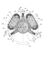
図12は図11の防振カメラにおける防振システム構造を示す斜視図であり、44は撮像素子である。53は補正レンズ52を図12の矢印58p,58y方向に自在に駆動して図11の矢印42p,42y方向の像振れ補正を行う振れ補正装置(詳細については後述)である。45p,45yは各々矢印46p,46y回りの振れを検出する角速度計や角加速度計等の振動検出部である。振動検出部45p,45yの出力は後述する演算部47p,47yを介して振れ補正装置53(詳しくは補正レンズ52)の駆動目標値に変換され、振れ補正装置53のコイルに入力される。これにより、像振れ補正が行われる。
FIG. 12 is a perspective view showing the structure of the image stabilization system in the image stabilization camera of FIG. 11, and 44 is an image sensor.
図13は図12に示した演算部47p,47yの詳細を示すブロック図であり、演算部47p,47yとも同様な為に、図13では演算部47pのみを用いて説明する。
FIG. 13 is a block diagram showing the details of the
演算部47pは、一点鎖線にて囲まれる、DCカットフィルタ兼増幅部48p、ローパスフィルタ兼増幅部49p、A/D変換部410p、カメラマイコン411および駆動部420pを有する。上記カメラマイコン411内には、記憶部412p、差動部413p、DCカットフィルタ414p、積分部415p、敏感度調整部416p、記憶部417p、差動部418pおよびPWMデューティ変換部419pを有する。
The
上記振動検出部45pとして、ここではカメラの振れ角速度を検出する振動ジャイロを用いており、振動ジャイロはカメラのメインスイッチのオンと同期して駆動され、カメラに加わる振れ角速度の検出を開始する。振動検出部45pの信号は、アナログ回路で構成されるDCカットフィルタ兼増幅部48pにて信号に重畳しているDCバイアス成分がカットされると共に適宜増幅される。
Here, a vibration gyro that detects a camera shake angular velocity is used as the
DCカットフィルタ兼増幅部48pは0.1Hz以下の周波数の信号をカットする周波数特性を有しており、カメラに加わる1〜10Hzの手振れ周波数帯域には影響が及ばないようになっている。しかしながら、このように0.1Hz以下をカットする特性にすると、振動検出部45pから振れ信号が入力されて完全にDCがカットされるまでには10秒近くかかってしまう。そこで、カメラのメインスイッチがオンされてから例えば0.1秒まではDCカットフィルタ兼増幅部48pの時定数を小さく(例えば10Hz以下の周波数の信号をカットする特性にする)しておく。この事で、0.1秒位の短い時間でDCをカットし、その後に時定数を大きくして(0.1Hz以下の周波数のみカットする特性にして)、DCカットフィルタ兼増幅部48pにより振れ角速度信号が劣化しないようにしている。
The DC cut filter /
DCカットフィルタ兼増幅部48pの出力は、アナログ回路で構成されるローパスフィルタ兼増幅部49pによりA/D変換の分解能に合わせて適宜増幅されると共に、振れ角速度信号に重畳する高周波のノイズをカットされる。これは振れ角速度信号をカメラマイコン411に入力する時のA/D変換部410pのサンプリングが振れ角速度信号のノイズにより読み誤りが起きるのを避ける為である。
The output of the DC cut filter /
ローパスフィルタ兼増幅部49pの出力は、A/D変換部410pによりサンプリングされてカメラマイコン411に取り込まれる。DCカットフィルタ兼増幅部48pによりDCバイアス成分はカットされている訳であるが、その後のローパスフィルタ兼増幅部49pの増幅により再びDCバイアス成分が振れ角速度信号に重畳している。その為に、カメラマイコン411内において再度DCカットを行う必要がある。
The output of the low-pass filter /
そこで、例えばカメラのメインスイッチのオンから0.2秒後にサンプリングされた振れ角速度信号を記憶部412pで記憶し、差動部413pにより記憶値と振れ角速度信号の差を求めることでDCカットを行う。尚、この動作では大雑把なDCカットしか出来ない(メインスイッチのオンから0.2秒後に記憶された振れ角速度信号の中にはDC成分ばかりでなく、実際の手振れも含まれている為)。その為に後段の、デジタルフィルタで構成されたDCカットフィルタ414pにより十分なDCカットを行っている。
Therefore, for example, a shake angular velocity signal sampled 0.2 seconds after the camera main switch is turned on is stored in the
DCカットフィルタ414pの時定数も、アナログのDCカットフィルタ兼増幅部48pと同様に、変更可能になっており、カメラのメインスイッチのオンから0.2秒後から更に0.2秒費やしてその時定数を徐々に大きくしている。具体的には、このDCカットフィルタ414pはメインスイッチのオンから0.2秒経過した時には10Hz以下の周波数をカットするフィルタ特性である。そして、その後50msec毎にフィルタでカットする周波数を5Hz、1Hz、0.5Hz、0.2Hzと下げてゆく。
The time constant of the
但し、上記動作の間に撮影者がシャッタレリーズボタンを半押し(sw1をオン)して測光、測距を行った時は直ちに撮影を行う可能性があり、時間を費やして時定数変更を行う事が好ましくない場合もある。 However, during the above operation, when the photographer presses the shutter release button halfway (sw1 is turned on) and performs photometry and distance measurement, there is a possibility that the image is taken immediately, and time constant is changed over time. Sometimes things are undesirable.
そこで、その様な時には撮影条件に応じて時定数変更を途中で中止する。例えば、測光結果により撮影シャッタスピードが1/60となる事が判明し、撮影焦点距離が150mmとする。この場合は、防振の精度はさほど要求されない為にDCカットフィルタ414pは0.5Hz以下の周波数をカットする特性まで時定数変更した時点で完了とする(シャッタスピードと撮影焦点距離の積により時定数変更量を制御する)。これにより、時定数変更の時間を短縮でき、シャッタチャンスを優先する事が出来る。勿論より速いシャッタスピード、或いは、より短い焦点距離の時には、DCカットフィルタ414pの特性は1Hz以下の周波数をカットする特性まで時定数変更した時点で完了とする。そして、より遅いシャッタスピード、長い焦点距離の時には時定数が最後まで変更完了するまで撮影を禁止する。
Therefore, in such a case, the time constant change is stopped halfway according to the shooting conditions. For example, it is found from the photometric result that the photographing shutter speed is 1/60, and the photographing focal length is 150 mm. In this case, since the accuracy of image stabilization is not so required, the
積分部415pは、DCカットフィルタ414pからの信号の積分を始め、角速度信号を角度信号に変換する。敏感度調整部416pは、積分された角度信号をその時のカメラの焦点距離、被写体距離情報により適宜増幅し、振れ角度に応じて適切な量、振れ補正装置53が動作するように変換する。ズーム、フォーカスにより撮影光学系が変化し、振れ補正装置53の駆動量に対し光軸偏心量が変わる為、この補正を行う必要がある。
The
シャッタレリーズボタンの半押しにより振れ補正装置53が動作し始める。尚、この時点で、振れ補正装置53による像振れ補正動作が急激に始まらないように注意する必要がある。記憶部417p及び差動部418pはこの対策の為に設けられている。記憶部417pは上記シャッタレリーズボタンの半押し時点で積分部415pの振れ角度信号を記憶する。差動部418pは積分部415pの信号と記憶部417pの信号の差を求める。その為、シャッタレリーズボタンの半押し時点における差動部418pの2つの信号入力は等しく、差動部418pの振れ補正装置53の駆動目標値信号はゼロであるが、その後ゼロより連続的に出力が行われる。記憶部417pはシャッタレリーズボタンの半押し時点の積分信号を原点にする役割となる。これにより、振れ補正装置53は急激に駆動される事が無くなる。
The
差動部418pからの目標値信号はPWMデューティ変更部419pに入力される。振れ補正装置53のコイルに振れ角度に対応した電圧或いは電流を印加すれば、補正レンズ52はその振れ角度に対応して駆動される。しかし、振れ補正装置53の駆動消費電力及びコイルの駆動トランジスタの省電力化の為にはPWM駆動が望ましい。そこで、PWMデューティ変更部419pは目標値に応じてコイル駆動デューティを変更している。例えば、周波数が20KHzのPWMにおいて差動部418pの目標値が2048の時にはデューティゼロ、4096の時にはデューティ100とし、その間を等分にしてデューティを目標値に応じて決定していく。尚、デューティの決定は目標値ばかりではなく、その時のカメラの撮影条件(温度やカメラの姿勢、バッテリーの状態)によって細かく制御して精度良い像振れ補正が行われるようにする。
The target value signal from the
PWMデューティ変更部419pの出力は、PWMドライバ等の公知の駆動部420pに入力され、駆動部420pの出力を振れ補正装置53のコイルに印加して像振れ補正を行う。駆動部420pはシャッタレリーズボタンの半押しより0.2秒経過した時点に同期してオンする。
The output of the PWM
図13では示していないが、撮影者がカメラのシャッタレリーズボタンの押し切り(sw2のオン)を行い、露光を開始したときも、このまま像振れ補正を継続しているので、像振れによる画質劣化を防ぐことが出来る。 Although not shown in FIG. 13, even when the photographer fully pushes the shutter release button of the camera (sw2 is turned on) and starts exposure, image blur correction is continued as it is. Can be prevented.
また、振れ補正装置53による像振れ補正は、シャッタレリーズボタンの半押しが継続される限り継続する。半押しが解除されると、記憶部417pが敏感度調整部416pの信号の記憶を止める(サンプリング状態になる)ので、差動部418pに入力される敏感度調整部416p及び記憶部417pの信号は等しくなり、差動部418pの出力はゼロになる。そのために振れ補正装置53にはゼロの駆動目標値が入力されることになり、像振れ補正が行われない。
Further, the image blur correction by the
カメラのメインスイッチをオフにしない限り、積分部415pは積分を継続しており、次のシャッタレリーズボタンの半押しで再び記憶部417pが新たな積分出力を記憶(信号ホールド)する。メインスイッチのオフで振動検出部45pが動作を停止し、防振シーケンスが終了する。
Unless the main switch of the camera is turned off, the
尚、積分部415pの信号が所定値より大きくなった時にはカメラのパンニングが行われたと判定して、DCカットフィルタ414pの時定数を変更する。例えば、0.2Hz以下の周波数をカットする特性であったものを、1Hz以下をカットする特性に変更し、再び所定時間で時定数をもとに戻していく。この時定数変更量も積分部415pの出力の大きさにより制御される。即ち、出力が第1の閾値を超えた時には、DCカットフィルタ414pの特性を0.5Hz以下をカットする特性にし、第2の閾値を超えた時には、1Hz以下をカットする特性にし、第3の閾値を超えた時には、5Hz以下をカットする特性にする。
When the signal of the
又、積分部415pの出力が非常に大きくなった時(例えば、カメラのパンニングなどの極めて大きな角速度が生じた場合)には、積分部415pを一旦リセットして演算上の飽和(オーバーフロー)を防止している。
Also, when the output of the
図13では、演算部47p内にDCカットフィルタ兼増幅部48p及びローパスフィルタ兼増幅部49pを設けているが、これらは振動検出部45p内に設けても良いのは言うまでもない。
In FIG. 13, the DC cut filter /
図14(a)〜図14(c)は振れ補正装置53の構成を示す図であり、図14(a)は正面図、図14(b)は図14(a)を矢印51方向より見た図、図14(c)は図14(a)のA―A断面図である。
14 (a) to 14 (c) are diagrams showing the configuration of the
図14において、補正レンズ52は支持枠53cに固定される。なお、図14(c)に示すように、補正レンズ52は、支持枠53cに固定される2枚のレンズ52a,52bと地板54に固定されるレンズ52cにより撮影光学系の群を構成している。
In FIG. 14, the
支持枠53cには強磁性材料のヨーク55が取り付けられ、ヨーク55の紙面裏面にはネオジウム等の永久磁石56p,56y(実際には見えない)が吸着固定されている。又、支持枠53cから放射状に延出する3本の支持軸53aは地板54の側壁54bに設けられた長孔54aに嵌合している。
A
図14(b)に示すように、支持軸53aと長孔54aの関係について述べると、補正レンズ52の光軸57方向には嵌合してガタは生じないが、光軸57と直交する方向には長孔54aが延びている。よって、支持枠53cは地板54に対し光軸57方向には移動規制されるが、光軸57と直交する平面内には自由に移動できる(矢印58p,58y,58r)。但し、支持枠53c上のピン53bと地板54上のピン54c間に引っ張りコイルバネ59が掛けられている為に各々の方向(58p,58y、58r)に弾性的に規制されている。
As shown in FIG. 14B, the relationship between the
地板54には永久磁石56p,56yに対向してコイル510p,510yが取り付けられている。ヨーク55、永久磁石56p、コイル510pの配置は図14(c)のようになっている(永久磁石56y、コイル510yも同じ配置)。そして、コイル510pに電流を流すと、支持枠53cは矢印58p方向に駆動され、コイル510yに電流を流すと、支持枠53cは矢印58y方向に駆動される。
その駆動量は各々の方向における引っ張りコイルバネ59のバネ定数とコイル510p,510yと永久磁石56p,56yの関連で生ずる推力との釣り合いで求まる。即ちコイル510p,510yに流す電流量に基づいて補正レンズ52の偏心量を制御できる。
The amount of driving is determined by a balance between the spring constant of the
ところで、最近のデジタルカメラは年々小型化が進んできており、それに伴い、振れ補正装置53の駆動高精度化が要求されるようになってきている。図9は振れ補正装置53の駆動周波数特性を示しており、横軸は駆動周波数、縦軸は駆動目標値に対する実際の駆動の比(利得)である。図9からわかるように、80Hz近傍の共振点(振れ補正作用部である補正レンズ52、支持枠53c、ヨーク55、永久磁石56p,56yの合計の質量と引っ張りコイルバネ59のバネ定数との関連で求まる)で20db程度のピークを持っている。そのため、この周波数近傍の振れが生じた場合には、目標値に対して10倍程度過剰に像振れ補正してしまう。今まではこのような高周波の振れは少なく、問題にはならなかった。しかしカメラの小型化に伴い、振れの周波数帯域が広くなってきたこと、又カメラ内のアクチュエータ(フォーカス駆動やズーム駆動)の強力化による発生振動とカメラが軽くなったことにより、高周波のカメラ振れを誘発する。その為、上記ピークも無視できなくなってきた。
By the way, recent digital cameras have been miniaturized year by year, and accordingly, driving accuracy of the
上記の点に鑑み、特許文献1(図4)においては、像振れを補正する為の補正レンズに駆動方向の制動を効かせる粘性手段を設けている。これにより、図10に示すように、共振点近傍におけるピークが無くなり、高精度な像振れ補正ができるようになっている。
しかしながら、上記従来例においては、機構的に制動を行う為に専用のスペースが必要である。その為に振れ補正装置の小型化が難しかった。 However, in the above-described conventional example, a dedicated space is required for mechanically braking. Therefore, it is difficult to reduce the size of the shake correction device.
(発明の目的)
本発明の目的は、小型を達成しつつ、高精度な像振れ補正を行うことのできる振れ補正装置および撮像装置を提供しようとするものである。
(Object of invention)
An object of the present invention is to provide a shake correction apparatus and an imaging apparatus capable of performing high-precision image shake correction while achieving a small size.
上記目的を達成するために、本発明は、光軸に直交する方向に移動可能な像振れ補正作用部と、前記像振れ補正作用部を支持する地板部と、前記像振れ補正作用部と前記地板部のいずれか一方に設けられたコイルと該像振れ補正作用部と該地板部の他方に設けられた永久磁石から成る、前記像振れ補正作用部を前記地板部に対して相対的に駆動させる駆動手段と、前記コイルの空芯部に配置される粘弾性部材と、一部が該粘弾性部材に挿入されると共に前記像振れ補正作用部と前記地板部のうち前記コイルが設けられた部材に対して固定されることなく前記コイルと前記永久磁石間に設けられる突起部とからなる、前記像振れ補正作用部と前記地板部を粘弾性結合させる振動吸収部材とを有する振れ補正装置とするものである。 In order to achieve the above object, the present invention provides an image shake correction operation unit that is movable in a direction orthogonal to the optical axis, a ground plane unit that supports the image shake correction operation unit, the image shake correction operation unit, Drives the image shake correcting operation portion relative to the ground plate portion, which comprises a coil provided on one of the ground plate portions, the image shake correcting action portion, and a permanent magnet provided on the other of the ground plate portions. driving means for, before and viscoelastic members that will be placed in the air-core portion of Kiko yl, partially provided with the coil of the ground plate portion and the image blur correcting action portion while being inserted into viscoelastic member A shake correction comprising the image shake correction action portion and a vibration absorbing member that viscoelastically couples the ground plane portion, which is composed of a protrusion provided between the coil and the permanent magnet without being fixed to a fixed member. It is a device.
同じく上記目的を達成するために、本発明は、本発明の上記振れ補正装置を有する撮像装置とするものである。 Similarly, in order to achieve the above object, the present invention provides an imaging apparatus having the shake correction apparatus of the present invention.
本発明を実施するための最良の形態は、以下の実施例1および2に示す通りである。 The best mode for carrying out the present invention is as shown in Examples 1 and 2 below.
図1は本発明の実施例1に係わる振れ補正装置を示す正面図、図2は図1のB−B断面図である。図1および図2において、11(11a,11b)は像振れ補正用の補正レンズ、12は補正レンズ11を保持する保持枠、13は振れ補正装置の地板である。保持枠12には、120度放射方向に腕12a,12b,12cが設けられており、腕12a〜12cには表面が平滑な、ステンレスなどの支持軸14a,14b,14cが圧入されている。
1 is a front view showing a shake correction apparatus according to
地板13には3点の側壁13a,13b,13cが設けられている。そして、保持枠12の腕12a,〜12cから放射状に延出する3本の支持軸14a〜14cが地板13の側壁13a〜13cに設けられた長孔13d,13e,13fに嵌合している(図14(b)の長穴54aと同様の構成であり、図1の方向からは見えない)。
The
図14(b)においても示したように、3本の支持軸14a〜14cと長孔13d〜13fの関係は、補正レンズ11の光軸方向(図1の紙面垂直方向)には嵌合してガタは生じない。しかし、光軸と直交する方向(図1の地板13における周方向13g)には長孔13d〜13fが延びている。よって、保持枠12は地板13に対し光軸方向には移動規制されるが、光軸と直交する平面内には自由に移動できる(ピッチ方向19p、ヨー方向19y、ロール方向19r)。
As shown in FIG. 14B, the relationship between the three
但し、保持枠12の腕先端部12d,12e,12fは圧縮コイルバネ15a,15b,15cの内径と締まりばめ嵌合している。そして、圧縮コイルバネ15a〜15cの外径も後述するバネ調整部材15g,15h,15i(15gは図2(a)の断面図に図示)と締まりばめ嵌合している。その為に、各々の方向(ピッチ方向19p、ヨー方向19y、ロール方向19r)に弾性的に規制されている。
However, the
ここで、締まりばめ嵌合について説明する。 Here, the interference fit fitting will be described.
圧縮コイルバネ15a〜15cのばね直径はコイルバネを圧縮してゆくにつれて大きくなってゆく。今、保持枠12の腕先端部12d〜12fおよびバネ調整部材15g〜15iの外径を圧縮コイルバネ15a〜15cを最大圧縮した時のコイル内径と隙間嵌合するように設定する。そして、圧縮コイルバネ15a〜15cを最大圧縮して保持枠12の腕先端部12d〜12fおよびバネ調整部材15g〜15iに押し込むと、バネがその圧縮が解除されると締まりばめとなる。そのため、圧縮コイルバネ15a〜15cと保持枠12の腕先端部12d〜12fおよびバネ調整部材15g〜15iは互いに強固に固定されてずれることがなくなる。
The spring diameters of the
保持枠12の耳部12g,12hには強磁性材料の吸着板17a,17bが取り付けられ(図1では点線で示している)、吸着板17a,17bの裏面側にはネオジウム等の永久磁石110a,110bが吸着固定されている。永久磁石110a,110bに対向し、地板13側にはコイル16a,16bが設けられている。
ここで、補正レンズ11、保持枠12、吸着板17a,17b、永久磁石110a,110b、支持軸14a〜14c、圧縮コイルバネ15a〜15cにより、像振れ補正作用部が構成される。また、地板13、バネ調整ねじ15d〜15f、バネ調整部材15g〜15iにより、地板部が構成される。
Here, the correction lens 11, the holding
図2では、支持軸14a、圧縮コイルバネ15a、ヨーク17a、永久磁石110a、および、コイル16aの配置を図示している。
FIG. 2 illustrates the arrangement of the
永久磁石110aの磁気回路はコイル16aに向かって垂直に貫いている為にコイル16aに電流を流すと、保持枠12は矢印18c方向(図1参照)に駆動され、同様にコイル16bに電流を流すと、保持枠12は矢印18d(図1参照)方向に駆動される。そして、その駆動量は各々の方向における圧縮コイルバネ15a〜15cのバネ定数と駆動コイル16a,16bと永久磁石110a,110bの関連で生ずる推力との釣り合いで求まる。即ち、コイル16a,16bに流す電流量に基づいて補正レンズ11の偏心量を制御できる。
Since the magnetic circuit of the
本実施例1の特徴は、図2において、コイル16aと永久磁石110aの間に振動吸収部材(以下、ダンパ部材とも記す)が設けられている点である。このダンパ部材は、コイル16aのボビン16cの空芯部設けられたUV硬化式のゲルあるいはダンピング効果の大きなゴムなどの粘弾性部材111aと、永久磁石110a側に押さえ部材112bを介して設けられた抵抗板112aとで構成されている。なお、抵抗板112aの先端部は粘弾性部材111aに挿入されている。
The feature of the first embodiment is that a vibration absorbing member (hereinafter also referred to as a damper member) is provided between the
ここで、像振れ補正作用部のうちの永久磁石110aから地板13(コイル16a)へ延出する抵抗板112aは直接地板13には固着されておらず、地板13に対しては粘弾性部材111aを介して自由に動き回ることができるので、駆動の妨げにはならない。
Here, the
図3は、上記ダンパ部材である抵抗板112aと粘弾性部材111aの平面図である。コイル16aの空芯部にはボビン16cを介して粘弾性部材111aが設けられており、永久磁石110a(半透明で示す)から紙面垂直側に延出した抵抗板112aが粘弾性部材111aに挿入されている。ここで、抵抗板112aは紙面左右方向に延びている(紙面上下方向が厚み方向になる板)。そのため、矢印18cの方向に対して抵抗板112aと粘弾性部材111aの接触面積が広く、駆動時には粘弾性部材111aの抵抗を大きく受ける。即ち、ダンピング効果が大きい。それに対して矢印18cと直角な方向は抵抗板112aと粘弾性部材111aの接触面積(抵抗板112aの厚み方向の接触面積)が狭く、駆動時に粘弾性部材111aの抵抗を受けにくい。
FIG. 3 is a plan view of the
ここで、矢印18c方向の駆動力は駆動コイル16aと永久磁石110aの関連で発生する訳であるが、コイル16aの中心部(空芯部)にてその駆動方向のダンピングを行っているので、駆動力とダンピング力の作用点が一致しており、安定した駆動が可能である。
Here, the driving force in the direction of the
一方、コイル16b、永久磁石110bで発生する駆動力(図3の矢印18cと直交する方向、図1では矢印18d)に関しては上述したようにダンピング力が少ない。よって、コイル16b、永久磁石110bで発生する駆動力が抵抗板112aにより不安定になる事はない。
On the other hand, with respect to the driving force generated in the
抵抗板112aはりん青銅などの非磁性のバネで構成されており、そのバネ定数は像振れ補正作用部の質量との関連の共振点が、図10における共振点より高く設定されている。
The
ここで、抵抗体112aを弾性材にしてある理由を説明する。粘弾性部材111aは衝撃などの高周波入力に対しては非常に硬くなる。そのため、そのような入力が発生した時は像振れ補正作用部の重さを全て抵抗板112aで支えることになる(上記条件ではダンパ部材が像振れ補正作用部と地板部の最も強固に結合する為)。これにより、以下の事故が予想される。
・抵抗板112aの破損
・粘弾性部材111aのボビン16cに対する剥離
これらを避けるために抵抗板112aを弾性部材で形成し、衝撃入力時には抵抗板112aがしなることで、衝撃を吸収する構造になっている(図4参照)。
Here, the reason why the
・ Damage of
上記のような粘弾性部材111aおよび抵抗板112aにより構成されるダンパ部材は、コイル16aだけではなく、コイル16bの空芯部においても同じ構造にて設けられている。尚、コイル16a側に抵抗板112aを設け、永久磁石110a側に粘弾性部材111aを設けても、同様な効果を期待できる。又、像振れ補正作用部側に永久磁石110aを設け、地板部側にコイル16aを設けているが、像振れ補正作用部側にコイル16aを、地板部側に永久磁石110aを、それぞれ設けた構成でも同様な効果を期待できる。
The damper member constituted by the
ここで、対のコイル16a,16bに電流を流して保持枠12をピッチ方向19p,ヨー方向19yに駆動する場合について説明する。
Here, a case where current is passed through the pair of
図5はこの為の駆動系の回路構成を示すブロック図である。ピッチ目標値31p及びヨー目標値31yは、各々ピッチ方向19p、ヨー方向19yに像振れ補正作用部を駆動する駆動目標値であり、図13における差動部418pの出力に相当する。この各々の目標値31p,31yは、各駆動方向の駆動力に応じてピッチ駆動力調整部32p、ヨー駆動力調整部32yでゲイン調整される。
FIG. 5 is a block diagram showing the circuit configuration of the drive system for this purpose. The
ピッチ駆動力調整部32pの出力はコイル駆動部34a(図13におけるPWMデューティ変換部419p、駆動部420pに相当)に入力されてコイル16aに電流として流れる。又、ピッチ駆動力調整部32pの出力は、加算部33bを介してコイル駆動部34b(図13におけるPWMデューティ変換部419p、駆動部420pに相当)に入力されてコイル16bに電流として流れる。即ち、ピッチ駆動目標値31aの信号によりコイル16a,16bに同相で同じ量の電流が流れる。
The output of the pitch driving
ヨー駆動力調整部32yの出力はコイル駆動部34b(図13におけるPWMデューティ変換部419p、駆動部420pに相当)に入力されてコイル16bに電流として流れる。又、ヨー駆動力調整部32yの出力は反転部33aを介してコイル駆動部34a(図13におけるPWMデューティ変換部419p、駆動部420pに相当)に入力されてコイル16aに電流として流される。即ち、ヨー駆動目標値31yの信号によりコイル16a,16bに互いに逆相で同じ量の電流が流れる。
The output of the yaw driving
コイル16a,16bに同相で同じ量の電流を流した場合、図6で示すように、コイル16aにより矢印18c方向に駆動力が発生し、コイル16bにより矢印18d方向に駆動力が発生する。よって、その合力は矢印18pのように、図1等のピッチ方向19pに沿った駆動力として発生する。又、このときの駆動力は二つのコイル16a,16bが120度配置になっていることから、互いのコイル16a,16bの駆動力の半分同士を合成してコイル16a或いはコイル16bの何れかのコイル一つ分と同じ駆動力として発生する。
When the same amount of current flows in the
また、コイル16a,16bに逆位相で同じ量の電流を流した場合、図7で示すように、コイル16aにより矢印18c方向に駆動力が発生し、コイル16bにより18d方向と反対方向(18’方向)に駆動力が発生する。よって、その合力は矢印18yのように、図1等のヨー方向19yに沿った駆動力として発生する。又、このときの駆動力は二つのコイル16a,16bが120度配置になっていることから、互いのコイル16a,16bの駆動力の√(3)/2同士を合成してコイル16a或いはコイル16bの何れかのコイルの√(3)倍の駆動力として発生する。
Further, when the same amount of current flows in the
このように駆動方向(19pと19y)で駆動力が異なってくるので、それらを揃えるために、図5に示すようにピッチ駆動力調整部32p、ヨー駆動力調整部32yを設けている。
As described above, since the driving force differs in the driving directions (19p and 19y), a pitch driving
尚、これら駆動力調整部32p,32yは、図5のように各目標値31p,31yの後段に設けるのではなく、図13で示した敏感度調整部416p(ヨー方向では不図示の416y)で調整を行っても良い。この様な構成にすると、ヨー方向19yへの駆動の場合にはコイル16a,16の√(3)倍の駆動力が発生し、この方向の駆動力が少なくて済む代わりに、ピッチ方向19pへの駆動の場合には駆動力の増加が無い。
The driving
一般に、ヨー方向の手振れ量はピッチ方向に比べて2倍近く大きい。 In general, the shake amount in the yaw direction is nearly twice as large as that in the pitch direction.
上記のようにピッチに対してヨーの振れが大きくなる現象は、デジタルカメラを片手で構え、カメラ背面の液晶モニターを観察して撮影する場合に特に顕著になる。このように方向による振れ量に合わせて駆動量を調節しているので、効率よく像振れ補正を行うことができる。 The phenomenon that the yaw shake increases with respect to the pitch as described above becomes particularly noticeable when the digital camera is held with one hand and the liquid crystal monitor on the back of the camera is observed for shooting. Since the drive amount is adjusted in accordance with the amount of shake depending on the direction as described above, image blur correction can be performed efficiently.
図2に戻って、圧縮コイルバネ15aは、前述したように、両端部を保持枠12の腕先端部12dおよびバネ調整部材15gの先端外径部15jと締まりばめ嵌合している。そのため、圧縮コイルバネ15aと保持枠12の腕先端部12dおよび側壁13aは互いに強固に固定されている。
Returning to FIG. 2, as described above, the
バネ調整部材15g(図1における15g〜15i)は側壁13a内に嵌合されており、支持軸方向15lにのみ摺動可能になっている。バネ調整ねじ15d(図1における15d〜15f)は側壁13aにねじ込まれており、先端部がバネ調整部材15gの調整受け部15kと当接する。そのために、バネ調整ねじ15dをねじ込むことでバネ調整部材15dは矢印15l方向に支持軸14aに沿って移動して、その方向の圧縮コイルバネ15aのバネチャージ力を調節する。
The
以上の実施例1によれば、コイル16a,16bの空芯部にダンパ部材である粘弾性部材111aと抵抗板112aを設けている。また、ダンピング効果の効く方向を定められる機構にしている。また、ダンパ部材により衝撃を吸収するようにしている。これらにより、小型且つ駆動が安定し、信頼性の高い振れ補正装置を実現可能となった。
According to the first embodiment described above, the
本実施例1における振れ補正装置の構成を詳しく説明すると、この振れ補正装置は、光軸10に対して略直交する平面内で駆動されて像振れを補正する像振れ補正作用部、像振れ補正作用部を支持する地板部を有する。さらに、像振れ補正作用部を地板部に対して相対的に駆動させる駆動部であるコイル16a,16b、このコイル16a,16bの空芯部に配置され、像振れ補正作用部と地板部を粘弾性結合させるダンパ部材を有する。なお、像振れ補正作用部は、補正レンズ11、保持枠12、吸着板17a,17b、永久磁石110a,110b、支持軸14a〜14cおよび圧縮コイルバネ15a〜15cから構成される。また、地板部は、地板13、バネ調整ねじ15d〜15fおよびバネ調整部材15g〜15iから構成される。また、ダンパ部材は、粘弾性部材111aおよび抵抗板112aから構成される。
The configuration of the shake correction apparatus according to the first embodiment will be described in detail. The shake correction apparatus is driven in a plane substantially orthogonal to the
また、像振れ補正作用部と地板部を第1の方向(矢印18c方向)に対して粘弾性結合し、第2の方向(矢印18cの直交する方向)に関しては、ダンパ部材を像振れ補正作用部と一体に駆動する。このことで、第2の方向には地板部と像振れ補正作用部間の粘弾性作用を生じない構成のダンパ部材とすることができる。
Further, the image blur correcting action part and the ground plane part are viscoelastically coupled with respect to the first direction (
また、地板部に設けられた粘弾性部材111aと、像振れ補正作用部に設けられ、粘弾性部材111aに挿入されると共に地板部に対して固着されない突起部となる抵抗板112aとでダンパ部材を構成している。そして、突起部となる抵抗板112aは像振れ補正作用部が駆動される第1の方向(矢印18c方向)に対する粘弾性部対抗面積と、第1の方向とは異なる第2の方向(矢印18cと直交する方向)に対する粘弾性部対抗面積を異なるようにしている。
Further, the damper member includes a
また、地板部に設けられた粘弾性部材111aと、像振れ補正作用部に設けられ、粘弾性部材111aに挿入されると共に地板部に対して固定されない弾性突起部となる抵抗板112aとでダンパ部材を構成している。或いは、像振れ補正作用部に設けられた粘弾性部材111aと、地板部に設けられ、粘弾性部材111aに挿入されると共に像振れ補正作用部に対して固定されない弾性突起部となる抵抗板112aとでダンパ部材を構成している。
The damper is composed of a
以上により、小型で、安定駆動が可能な、信頼性の高い振れ補正装置が実現できた。 As described above, a highly reliable shake correction apparatus that is compact and can be driven stably has been realized.
図8は本発明の実施例2に係わる振れ補正装置に具備されるダンパ部材近傍を示す平面図及び断面図である。詳しくは、図8(a)はコイル16a、永久磁石110aおよびダンパ部材(抵抗板112aと粘弾性部材111aより成る)の平面図、図8(b)はその断面図である。尚、図8において、コイル16aが像振れ補正作用部に取り付けられ、永久磁石110aが地板部に取り付けられても、或いはその逆でも構わない。
8A and 8B are a plan view and a cross-sectional view showing the vicinity of a damper member provided in the shake correction apparatus according to the second embodiment of the present invention. Specifically, FIG. 8A is a plan view of the
本発明の実施例2の振れ補正装置において、上記実施例1と異なるのは、以下の点である。 The shake correction apparatus according to the second embodiment of the present invention differs from the first embodiment in the following points.
粘弾性体111aを収納するケース111bが設けられ、ケース111bはコイル16aのボビン16c内で矢印18c方向には固定され(ボビン16cに挟まれている為)、それと直交する方向には自由に摺動可能な構成になっている。
A
また、永久磁石110aから延出する抵抗板112aは弾性体の棒状になっている。即ち、抵抗板112aはダンピングの方向性を決める形状になっていないが、粘弾性部材111a自身がダンピングを効かせたくない方向には像振れ補正作用部と一体になって動く構成になっている。
Further, the
図8においては、111a’、112a’は矢印18cと直交方向に像振れ補正作用部が移動したときの、粘弾性部材111a及び抵抗板112aの摺動後の位置を示すものである。このように矢印18cと直交方向の駆動に関してはダンピング作用が全く効かない。
In FIG. 8, 111 a ′ and 112 a ′ indicate positions after sliding of the
この矢印18c方向の駆動力はコイル16bにより発生するのである。しかし、その駆動力のダンピングをコイル16a側のダンパが行ってしまうと、駆動推力方向とダンピング位置のずれによる駆動精度劣化(図1におけるローリング方向19rの回転発生)を起こすことになる。図8のようなダンピング構成であると、コイル16bの駆動力に対し、コイル16aに設けられたダンパ部材のダンピング抵抗は生じない。コイル16aの駆動力に対し、コイル16bに設けられたダンパ部材のダンピング抵抗も生じない。
The driving force in the direction of the
コイル16aの推力方向18cに対するダンピングは、コイル16aの空芯部に設けられたダンパ部材で行い、コイル16bの推力方向18dに対するダンピングは、コイル16bの空芯部に設けられたダンパ部材で行う。これにより、図10で示した素直な周波数特性の駆動を実現できる。
Damping of the
抵抗板112aは弾性棒のため、衝撃などの高周波の入力があった場合には抵抗板112aでその吸収を行う。そのため、衝撃による故障を防ぐことも出来る。
Since the
以上の実施例2によれば、コイル16a,116bの空芯部にダンパ部材を設けたこと、ダンピング効果の効く方向を定められる機構にしたことで、小型且つ駆動が安定し、信頼性の高い振れ補正装置を実現可能となった。
According to the second embodiment described above, a damper member is provided in the air core portions of the
本実施例2における振れ補正装置の構成を詳しく説明すると、この振れ補正装置は、光軸10に対して略直交する平面内で駆動されることで像振れを補正する像振れ補正作用部、像振れ補正作用部を支持する地板部を有する。さらに、地板部を第1の方向(矢印18c)に対して粘弾性結合させると共に第2の方向(矢印18cと直交方向)に関しては、像振れ補正作用部と一体に駆動されて地板部と像振れ補正作用部間の粘弾性作用を生じない構成のダンパ部材を有する。
The configuration of the shake correction apparatus according to the second embodiment will be described in detail. The shake correction apparatus is driven in a plane substantially orthogonal to the
よって、高精度の振れ補正駆動を行える振れ補正装置を実現できた。 Therefore, a shake correction apparatus that can perform highly accurate shake correction drive can be realized.
最後に、上記の実施例1および2による効果をあらためて述べる。デッドスペースであるコイル16a,16bの空芯部にダンパ部材を配置することで、装置の大きさを変えずに、効率的な制動を行えるようにしている。又、ダンパ部材の作用する方向を定めることで、制動により駆動方向が不安定にならないようにしている。更に、ダンパ部材は高周波の外乱に対しては極めて硬くなるので、そのような外乱が入力された時にでも、振れ補正装置の破損が生じないようにしている。
Finally, the effect of the first and second embodiments will be described again. By disposing a damper member in the air core portions of the
つまり、
1)ダンピング機構の小型化(振れ補正装置に専用のスペースを必要としない)
2)ダンピング方向の安定化(ダンピングの効く方向を定める)
3)駆動精度の向上(駆動力とダンピング力の発生位置を一致させる)
4)事故対策(衝撃や落下時の破損防止)
の4つの効果を実現できる振れ補正装置とすることができた。
In other words,
1) Downsizing of the damping mechanism (no special space is required for the shake correction device)
2) Stabilization of damping direction (determining the direction in which damping is effective)
3) Improvement of driving accuracy (matching the driving force and damping force generation position)
4) Measures against accidents (preventing damage during impact or dropping)
Thus, a shake correction apparatus capable of realizing the following four effects can be obtained.
(本発明と実施例の対応)
補正レンズ11、保持枠12、吸着板17a,17b、永久磁石110a,110b、支持軸14a〜14cおよび圧縮コイルバネ15a〜15cが本発明の像振れ補正作用部に相当する。また、地板13、バネ調整ねじ15d〜15fおよびバネ調整部材15g〜15iが地板部に相当する。また、ヨーク17a,17b、永久磁石110a,110bおよびコイル16a,16bが駆動手段に相当する。また、粘弾性部に相当する粘弾性部材111aおよび突起部に相当する抵抗板112aより成るダンパ部材が本発明の振動吸収部材に相当する。なお、粘弾性部は、地板部と像振れ補正作用部の一方に設けられている。また、突起部は、像振れ補正作用部と前記地板部の他方に設けられ、粘弾性部に挿入されると共に地板部或いは振れ補正作用部に対して固定されない構成となっている。
(Correspondence between the present invention and the embodiment)
The correction lens 11, the holding
以上、デジタルカメラの防振システムを例にして説明を続けてきた。しかし、本発明の装置は小型で高安定な機構にまとめることが出来るので、デジタルカメラに限らず、デジタルビデオカメラや、監視カメラ、Webカメラ、携帯電話などにも展開できる。 The description has been continued with the digital camera image stabilization system as an example. However, since the apparatus of the present invention can be integrated into a small and highly stable mechanism, it can be developed not only for digital cameras but also for digital video cameras, surveillance cameras, Web cameras, mobile phones, and the like.
10 光軸
11 補正レンズ
12 保持枠
13 地板
14a,14b,14c 支持軸
15a,15b,15c 圧縮コイルバネ
15d,15e,15f バネ調整ねじ
15g,15h,15i バネ調整部材
16a,16b コイル
17a,17b 吸着板
110a,110b 永久磁石
111a 粘弾性部材
111b ケース
112a 抵抗板
DESCRIPTION OF
Claims (7)
前記像振れ補正作用部を支持する地板部と、
前記像振れ補正作用部と前記地板部のいずれか一方に設けられたコイルと該像振れ補正作用部と該地板部の他方に設けられた永久磁石から成る、前記像振れ補正作用部を前記地板部に対して相対的に駆動させる駆動手段と、
前記コイルの空芯部に配置される粘弾性部材と、一部が該粘弾性部材に挿入されると共に前記像振れ補正作用部と前記地板部のうち前記コイルが設けられた部材に対して固定されることなく前記コイルと前記永久磁石間に設けられる突起部とからなる、前記像振れ補正作用部と前記地板部を粘弾性結合させる振動吸収部材とを有することを特徴とする振れ補正装置。 An image stabilization unit that is movable in a direction perpendicular to the optical axis;
A base plate portion that supports the image shake correcting operation portion;
The image stabilization unit comprising the coil provided on one of the image stabilization unit and the ground plate, and the permanent magnet provided on the other of the image stabilization unit and the ground plate is disposed on the ground plate. Drive means for driving relative to the part;
Before and viscoelastic members that will be placed in the air-core portion of Kiko yl respect member to which the coil is provided of the ground plate portion and the image blur correcting action unit with a portion is inserted into the viscoelastic member And a vibration absorbing member that includes a projection provided between the coil and the permanent magnet without being fixed, and a vibration absorbing member that viscoelastically couples the ground plate portion. apparatus.
前記収納部材は前記コイルの駆動力発生方向に対して固定されるように、該駆動力発生方向および前記光軸に直交する方向に対しては移動可能になるように前記コイルに配置されることを特徴とする請求項2に記載の振れ補正装置。The storage member is disposed on the coil so as to be movable in the driving force generation direction and the direction orthogonal to the optical axis so that the storage member is fixed with respect to the driving force generation direction of the coil. The shake correction apparatus according to claim 2.
Priority Applications (1)
| Application Number | Priority Date | Filing Date | Title |
|---|---|---|---|
| JP2007080756A JP4956254B2 (en) | 2007-03-27 | 2007-03-27 | Vibration correction apparatus and imaging apparatus |
Applications Claiming Priority (1)
| Application Number | Priority Date | Filing Date | Title |
|---|---|---|---|
| JP2007080756A JP4956254B2 (en) | 2007-03-27 | 2007-03-27 | Vibration correction apparatus and imaging apparatus |
Publications (3)
| Publication Number | Publication Date |
|---|---|
| JP2008241967A JP2008241967A (en) | 2008-10-09 |
| JP2008241967A5 JP2008241967A5 (en) | 2010-04-15 |
| JP4956254B2 true JP4956254B2 (en) | 2012-06-20 |
Family
ID=39913427
Family Applications (1)
| Application Number | Title | Priority Date | Filing Date |
|---|---|---|---|
| JP2007080756A Expired - Fee Related JP4956254B2 (en) | 2007-03-27 | 2007-03-27 | Vibration correction apparatus and imaging apparatus |
Country Status (1)
| Country | Link |
|---|---|
| JP (1) | JP4956254B2 (en) |
Families Citing this family (6)
| Publication number | Priority date | Publication date | Assignee | Title |
|---|---|---|---|---|
| JP2010096859A (en) * | 2008-10-14 | 2010-04-30 | Nidec Sankyo Corp | Optical unit with shake correcting function |
| KR102386927B1 (en) * | 2014-01-28 | 2022-04-15 | 엘지이노텍 주식회사 | Lens moving unit and camera module and smartphone having the same |
| JP6310328B2 (en) * | 2014-05-29 | 2018-04-11 | 日本電産コパル株式会社 | LENS DRIVE DEVICE, CAMERA MODULE HAVING LENS DRIVE DEVICE, AND ELECTRONIC DEVICE |
| JP6405135B2 (en) * | 2014-06-30 | 2018-10-17 | 日本電産コパル株式会社 | Lens drive device |
| JP7250458B2 (en) * | 2018-08-24 | 2023-04-03 | 日本電産サンキョー株式会社 | Optical unit with anti-shake function |
| KR102525237B1 (en) * | 2020-09-18 | 2023-04-24 | 엘지이노텍 주식회사 | Lens moving unit and camera module and smartphone having the same |
Family Cites Families (4)
| Publication number | Priority date | Publication date | Assignee | Title |
|---|---|---|---|---|
| JPH0281009A (en) * | 1988-09-19 | 1990-03-22 | Canon Inc | Supporting structure for optical element holding frame |
| JP4669118B2 (en) * | 2000-10-31 | 2011-04-13 | キヤノン株式会社 | Vibration correction apparatus and optical apparatus |
| JP2005338298A (en) * | 2004-05-25 | 2005-12-08 | Sumida Corporation | Blur correcting optical device |
| US7710459B2 (en) * | 2004-07-21 | 2010-05-04 | Hewlett-Packard Development Company, L.P. | Ferrofluid suspension for image stabilization |
-
2007
- 2007-03-27 JP JP2007080756A patent/JP4956254B2/en not_active Expired - Fee Related
Also Published As
| Publication number | Publication date |
|---|---|
| JP2008241967A (en) | 2008-10-09 |
Similar Documents
| Publication | Publication Date | Title |
|---|---|---|
| JP4659465B2 (en) | Vibration correction apparatus and optical apparatus | |
| JP2009258389A (en) | Image blur correction apparatus, imaging apparatus and optical apparatus | |
| JP5094606B2 (en) | Image shake correction apparatus, optical apparatus including the same, image pickup apparatus, and image shake correction apparatus control method | |
| US7634181B2 (en) | Image stabilizing system and optical apparatus | |
| JP5031690B2 (en) | Anti-vibration control device, imaging device, and control method for image stabilization control device | |
| JP4956254B2 (en) | Vibration correction apparatus and imaging apparatus | |
| JP2010025961A (en) | Image stabilization control apparatus and image capturing apparatus | |
| JP2005217993A (en) | Photographing apparatus | |
| JP3530643B2 (en) | Lens barrel and optical equipment using the same | |
| JP5094523B2 (en) | Image shake correction apparatus, imaging apparatus, and optical apparatus | |
| JPH09211518A (en) | Camera and vibration-proof device | |
| US6757488B2 (en) | Control apparatus for image blur correction | |
| JP2003091028A (en) | Controller for positioning correcting means | |
| JP2006267752A (en) | Image blur correction device and optical equipment | |
| JP4669118B2 (en) | Vibration correction apparatus and optical apparatus | |
| JP4329151B2 (en) | Shake detection device and camera shake correction camera | |
| JP4174240B2 (en) | Vibration correction apparatus and optical apparatus provided with the same | |
| JP3526278B2 (en) | Image stabilization optical device | |
| JP2754872B2 (en) | Image blur prevention device | |
| JP4817544B2 (en) | Anti-vibration control device, camera and correction means position control device | |
| JP2003075880A (en) | Optical device | |
| JP2003107552A (en) | Photographic device | |
| JP4974952B2 (en) | Image shake correction apparatus, imaging apparatus, and optical apparatus | |
| JP2003057708A (en) | Shake correcting optical device | |
| JP2002303908A (en) | Optical device, lens barrel and camera |
Legal Events
| Date | Code | Title | Description |
|---|---|---|---|
| A521 | Request for written amendment filed |
Free format text: JAPANESE INTERMEDIATE CODE: A523 Effective date: 20100303 |
|
| A621 | Written request for application examination |
Free format text: JAPANESE INTERMEDIATE CODE: A621 Effective date: 20100303 |
|
| RD01 | Notification of change of attorney |
Free format text: JAPANESE INTERMEDIATE CODE: A7421 Effective date: 20100520 |
|
| RD01 | Notification of change of attorney |
Free format text: JAPANESE INTERMEDIATE CODE: A7421 Effective date: 20100630 |
|
| A131 | Notification of reasons for refusal |
Free format text: JAPANESE INTERMEDIATE CODE: A131 Effective date: 20111213 |
|
| A977 | Report on retrieval |
Free format text: JAPANESE INTERMEDIATE CODE: A971007 Effective date: 20111214 |
|
| A521 | Request for written amendment filed |
Free format text: JAPANESE INTERMEDIATE CODE: A523 Effective date: 20120206 |
|
| TRDD | Decision of grant or rejection written | ||
| A01 | Written decision to grant a patent or to grant a registration (utility model) |
Free format text: JAPANESE INTERMEDIATE CODE: A01 Effective date: 20120313 |
|
| A01 | Written decision to grant a patent or to grant a registration (utility model) |
Free format text: JAPANESE INTERMEDIATE CODE: A01 |
|
| A61 | First payment of annual fees (during grant procedure) |
Free format text: JAPANESE INTERMEDIATE CODE: A61 Effective date: 20120316 |
|
| R151 | Written notification of patent or utility model registration |
Ref document number: 4956254 Country of ref document: JP Free format text: JAPANESE INTERMEDIATE CODE: R151 |
|
| FPAY | Renewal fee payment (event date is renewal date of database) |
Free format text: PAYMENT UNTIL: 20150323 Year of fee payment: 3 |
|
| LAPS | Cancellation because of no payment of annual fees |