JP5031690B2 - Anti-vibration control device, imaging device, and control method for image stabilization control device - Google Patents
Anti-vibration control device, imaging device, and control method for image stabilization control device Download PDFInfo
- Publication number
- JP5031690B2 JP5031690B2 JP2008183428A JP2008183428A JP5031690B2 JP 5031690 B2 JP5031690 B2 JP 5031690B2 JP 2008183428 A JP2008183428 A JP 2008183428A JP 2008183428 A JP2008183428 A JP 2008183428A JP 5031690 B2 JP5031690 B2 JP 5031690B2
- Authority
- JP
- Japan
- Prior art keywords
- shake
- output
- correction
- frequency
- accelerometer
- Prior art date
- Legal status (The legal status is an assumption and is not a legal conclusion. Google has not performed a legal analysis and makes no representation as to the accuracy of the status listed.)
- Expired - Fee Related
Links
Images


Classifications
-
- G—PHYSICS
- G03—PHOTOGRAPHY; CINEMATOGRAPHY; ANALOGOUS TECHNIQUES USING WAVES OTHER THAN OPTICAL WAVES; ELECTROGRAPHY; HOLOGRAPHY
- G03B—APPARATUS OR ARRANGEMENTS FOR TAKING PHOTOGRAPHS OR FOR PROJECTING OR VIEWING THEM; APPARATUS OR ARRANGEMENTS EMPLOYING ANALOGOUS TECHNIQUES USING WAVES OTHER THAN OPTICAL WAVES; ACCESSORIES THEREFOR
- G03B17/00—Details of cameras or camera bodies; Accessories therefor
Abstract
Description
本発明は、手振れ等の振れによる画像振れを補正(画像の劣化を防止)する防振制御装置及び撮像装置並びに防振制御装置の制御方法に関するものである。 The present invention relates to an image stabilization control apparatus, an imaging apparatus , and a control method for an image stabilization control apparatus that correct image blur due to camera shake or the like (prevent image degradation).
現在のカメラは露出決定やピント合わせ等の撮影にとって重要な作業は全て自動化され、カメラ操作に未熟な人でも撮影失敗を起こす可能性は非常に少なくなっている。また、最近では、手振れ等による画像振れを防ぐ防振制御装置(振れ補正部、駆動部及び振動検出部などから成る)を備えたカメラも製品化されてきており、撮影者の撮影ミスを誘発する要因は殆ど無くなってきている。 With the current camera, all the important tasks for shooting such as determining exposure and focusing are automated, and it is very unlikely that people who are unskilled in camera operation will fail to shoot. Recently, a camera equipped with an image stabilization control device (consisting of a shake correction unit, a drive unit, a vibration detection unit, etc.) that prevents image shake due to camera shake has been commercialized, causing a photographer to take a mistake. The factor to do is almost gone.
ここで、画像振れを防ぐ防振制御装置について簡単に説明する。 Here, the image stabilization control apparatus for preventing image blur will be briefly described.
撮影時のカメラの手振れは、周波数として通常1Hzないし10Hzの振動である。そして、シャッタのレリーズ時点においてこのような手振れを起こしていても画像振れの無い写真を撮影可能とする為には、手振れによるカメラの振動を検出し、その検出値に応じて画像振れ補正用のレンズ(以下、補正レンズ)を変位させなければならない。 The camera shake at the time of shooting is usually a vibration of 1 Hz to 10 Hz as a frequency. Then, in order to be able to take a picture without image blur even when such a camera shake occurs at the shutter release time, the camera shake due to the camera shake is detected, and an image shake correction is performed according to the detected value. The lens (hereinafter, correction lens) must be displaced.
従って、カメラに振れが生じても画像振れが生じない写真を撮影するためには、第1に、カメラの振動を正確に検出し、第2に、手振れ等の振れによる光軸変化を補正することが必要となる。上記振動(カメラ振れ)の検出は、原理的にいえば、加速度、角加速度、角速度、角変位等を検出し、カメラ振れ補正の為にその出力を適宜演算処理する振動検出部をカメラに搭載することによって行うことができる。そして、この振動検出部からの信号に基づいて光軸を変位させる振れ補正部(詳しくは補正レンズ)を駆動部により駆動することにより、画像振れ抑制が行われる。 Therefore, in order to take a photograph that does not cause image shake even if the camera shakes, firstly, the camera vibration is accurately detected, and second, the optical axis change due to shake such as camera shake is corrected. It will be necessary. In principle, the above vibration (camera shake) is detected by detecting the acceleration, angular acceleration, angular velocity, angular displacement, etc., and installing a vibration detection unit in the camera that appropriately calculates the output for camera shake correction. Can be done. Then, image blur suppression is performed by driving a shake correction unit (specifically, a correction lens) for displacing the optical axis based on a signal from the vibration detection unit by the drive unit.
ここで、防振制御装置を具備した従来の一眼レフカメラについて、図48及び図49を用いて説明する。尚、図48は一眼レフカメラの平面図であり、図49はその側面図である。 Here, a conventional single-lens reflex camera equipped with an image stabilization control device will be described with reference to FIGS. 48 and 49. FIG. 48 is a plan view of a single-lens reflex camera, and FIG. 49 is a side view thereof.
図48及び図49において、4804はカメラ本体であり、該カメラ本体4804に対し、後述する振れ補正部が具備される交換式の撮影レンズ4801が装着される。後述の振れ補正部は、光軸4802に対して矢印4803p,4803yで示すカメラ縦振れ及び横振れ(以下、角度振れ)に対して画像振れ補正を行うものである。
48 and 49,
4804aはレリーズボタン、4804bはモードダイアル(メインスイッチを含む)、4804cはリトラクタブルストロボ、4804dはカメラCPU、4805は撮像素子であり、これらはカメラ本体4804に具備されている。
4804a is a release button, 4804b is a mode dial (including a main switch), 4804c is a retractable strobe, 4804d is a camera CPU, 4805 is an image sensor, and these are provided in the
4806は補正レンズ4806aやコイル、永久磁石等を含む振れ補正部であり、後述の駆動部によりコイルへの通電がなされ、該コイルと永久磁石との関連により補正レンズ4806aが矢印4806p,4806y方向に自在に移動させられる。これにより、矢印4803p,4803y方向の画像振れ補正が行われる。4807p,4807yは各々矢印4803p,4803y回りの振れを検出する振動検出部であるところの角速度計(gyro)であり、矢印4807pa,4807ya方向の検出感度方向を持つ。この角速度計4807p,4807yで検出された角速度出力はレンズCPU4808で演算され、ここで振れ補正部4806、詳しくは補正レンズ4806aの駆動目標値に変換される。
カメラ本体4804に設けられたレリーズボタン4804aの半押し(スイッチS1のオン:撮影準備の為に測光、ピント合わせを指令する操作)に同期して、駆動目標値は駆動部(driver)4809に入力される。そして、駆動部4809により振れ補正部4806に具備されるコイルが駆動される。これにより、上記したように補正レンズ4806aがコイルと永久磁石との関係により光軸と直交する平面内において画像振れを抑制する矢印4806p,4806y方向に移動させられるようになる。つまり、矢印4803p,4803y方向の画像振れ補正が開始される。
The drive target value is input to a
防振制御装置は、振れ補正部4806、角速度計4807p,4807y、レンズCPU4808、及び、駆動部4809などにより構成される。
The image stabilization control device includes a
図48及び図49を用いて説明した防振制御装置では、手振れ等の振動検出用に角速度計4807p,4807yを用いている。カメラ本体4804には、矢印4803p,4803y回りの角度振ればかりではなく、矢印101pb,101ybに示した様に並進振動(以下、平行振れ)も加わり、レンズの主点位置における並進運動も画像振れに影響してくる。しかし、一般的な撮影条件では矢印4803p,4803y回りの角度振れ(回転振れ)が支配的であり、矢印101pb,101ybに示した平行振れによる像劣化は少ない。そのため、振動検出用には角速度計4807p,4807yだけを設ければよかった。
In the image stabilization control apparatus described with reference to FIGS. 48 and 49, the
ところが、至近距離での撮影(撮影倍率の高い撮影条件)では、矢印101pb,101ybに示した平行振れによる像劣化も無視できなくなってくる。例えばマクロ撮影のように、被写体に20cm程度まで接近して撮影する条件や、被写体は1m程度に位置しているとする。この場合でも、撮像光学系の焦点距離が非常に大きい(例えば400mm)条件下では積極的に平行振れを検出して振れ補正部4806を駆動する必要が出てくる。
However, in close-up shooting (shooting conditions with a high shooting magnification), image degradation due to parallel shake indicated by arrows 101pb and 101yb cannot be ignored. For example, it is assumed that a subject is photographed as close to 20 cm as in macro photography, and the subject is located at about 1 m. Even in this case, under the condition that the focal length of the imaging optical system is very large (for example, 400 mm), it is necessary to positively detect the parallel shake and drive the
特許文献1では、加速度を検出する加速度計を設け、この加速度計で平行振れを検出して、別に設けた角速度計の出力と共に振れ補正部を駆動する技術が開示されている。
しかしながら、上記の従来技術では、平行振れの検出に用いる加速度計の出力は外乱ノイズや温度などの環境変化でその信号が変化する虞があり、平行振れの高精度な補正が難しいものであった。 However, in the above prior art, the output of the accelerometer used for detecting parallel shake may change its signal due to environmental changes such as disturbance noise and temperature, and it is difficult to correct parallel shake with high accuracy. .
(発明の目的)
本発明の目的は、平行振れの高精度な画像振れ補正を行うことのできる防振制御装置及び撮像装置を提供しようとするものである。
(Object of invention)
An object of the present invention is to provide an image stabilization control apparatus and an imaging apparatus capable of performing highly accurate image shake correction of parallel shake.
上記目的を達成するために、本発明は、振れによる画像振れを補正する振れ補正手段と、振れの角速度を検出する第1振れ検出手段と、前記第1振れ検出手段とは異なる方式で振れを検出する第2振れ検出手段と、前記第1振れ検出手段の出力に基づいて前記振れ補正手段を駆動する補正量を演算する第1の演算手段と、前記第1振れ検出手段の出力に基づく第1信号と前記第2振れ検出手段の出力に基づく第2信号とから補正値を演算し、該補正値によって補正された前記第1振れ検出手段の出力に基づいて前記振れ補正手段を駆動する補正量を演算する第2の演算手段と、前記第1の演算手段および/または前記第2の演算手段によって演算された補正量に基づいて前記振れ補正手段を駆動する駆動制御手段と、前記補正値に見かけ上周波数依存性を持たせるために、前記第2の演算手段の周波数特性を前記第1の演算手段の周波数特性とは異ならせる周波数帯域変更手段とを有することを特徴とする防振制御装置とするものである。 In order to achieve the above object, the present invention provides a shake correction means for correcting image shake due to shake, a first shake detection means for detecting an angular velocity of shake, and a shake different from the first shake detection means. A second shake detection means for detecting; a first calculation means for calculating a correction amount for driving the shake correction means based on the output of the first shake detection means; and a first calculation means based on the output of the first shake detection means. Correction for calculating a correction value from one signal and a second signal based on the output of the second shake detection means, and driving the shake correction means based on the output of the first shake detection means corrected by the correction value Second calculation means for calculating the amount, drive control means for driving the shake correction means based on the correction amount calculated by the first calculation means and / or the second calculation means, and the correction value Apparently In order to provide several dependent, image stabilization control apparatus according to claim Rukoto that having a frequency bandwidth changing means for varying the frequency characteristic of the first operation means the frequency characteristic of the second arithmetic means It is what.
また、上記目的を達成するために、本発明は、上記本発明の防振制御装置を具備する撮像装置とするものである。 In order to achieve the above object, the present invention is an imaging apparatus including the image stabilization control apparatus of the present invention.
本発明によれば、小型で機動性が高く、常に平行振れの高精度な補正を行うことができる防振制御装置又は撮像装置並びに防振制御装置の制御方法を提供できるものである。 According to the present invention, it is possible to provide a vibration control device or an imaging device and a control method for the vibration control device that are small in size, high in mobility, and capable of always performing highly accurate correction of parallel shake.
本発明を実施するための最良の形態は、以下の実施例1および2に示す通りである。 The best mode for carrying out the present invention is as shown in Examples 1 and 2 below.
図1及び図2は本発明の実施例1に係わる防振制御装置を具備した一眼レフカメラを示す平面図及び側面図であり、図48及び図49の従来例と同じ部分は同一符号を付してある。図48及び図49の従来例と異なるのは、カメラ(防振制御装置)に加わる振れを検出する振動検出部として、角速度計4807p,4807yに加え、加速度を検出する加速度計(acc)101p,101yを設けている点である。この加速度計101p,101y各々の加速度検出軸は矢印101pa,101yaである。
FIGS. 1 and 2 are a plan view and a side view showing a single-lens reflex camera equipped with an image stabilization control apparatus according to
角速度計4807p,4807y及び加速度計101p,101yの出力はともにレンズCPU4808に入力される。そして、それら出力の関連により駆動部4809によって振れ補正部4806が駆動される。
The outputs of the
図3は、本発明の実施例1に係る防振制御装置を示すブロック図である。図3では、カメラの鉛直方向に生じる振れ(ピッチ方向:図1及び図2の矢印4806p,101pb方向)の構成のみを示している。しかし、同様な構成はカメラの水平方向に生じる振れ(ヨー方向:図1及び図2の矢印4806y,101yb方向)にも設けられている。これらは基本的には同じ構成になっているので、以下ピッチ方向の構成のみを図示し、その説明を行う。
FIG. 3 is a block diagram illustrating the image stabilization control apparatus according to the first embodiment of the present invention. FIG. 3 shows only the configuration of shake (pitch direction: directions of
図3を用いて、まず、角度振れの補正について説明する。 First, correction of angular shake will be described with reference to FIG.
角速度計4807pからの角速度信号はレンズCPU4808に取り込まれる。そして、その角速度信号はHPF積分フィルタ301に入力され、HPF(ハイパスフィルタ或いは高域透過フィルタ)でDC成分をカットされた後に積分され、角度信号に変換される。尚、HPF処理や積分処理は量子化された角速度信号をレンズCPU4808内で演算処理することで得られ、公知の差分方程式などで実現可能である。また、レンズCPU4808に入力される前に、コンデンサや抵抗を利用してアナログ回路で実現する事も可能である。
An angular velocity signal from the
ここで、手振れの周波数帯域は1Hz〜10Hzの間である。そのため、HPFとしては例えば手振れの周波数帯域から十分離れた、例えば0.1Hz以下の周波数成分をカットする1次のHPF特性になっている。この事を以後、“0.1Hz折点1次HPF処理”と記す。 Here, the frequency band of camera shake is between 1 Hz and 10 Hz. For this reason, the HPF has a primary HPF characteristic that cuts a frequency component, for example, 0.1 Hz or less, which is sufficiently away from the frequency band of camera shake, for example. This is hereinafter referred to as “0.1 Hz break primary HPF processing”.
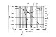
図4及び図5はその説明をするためのHPF特性のボード線図であり、横軸は周波数、縦軸は利得及び位相であり、手振れの帯域を矢印404で示す。尚、利得は角速度計4807pの出力に対するHPF積分フィルタ301の出力比をデシベル表示で示している。
FIG. 4 and FIG. 5 are Bode diagrams of HPF characteristics for the purpose of explanation. The horizontal axis represents frequency, the vertical axis represents gain and phase, and a hand shake band is indicated by an
ここで、図4の“1Hz折点1次HPF処理”では、利得401は1Hz以下の周波数が減衰される特性になっているが、手振れの下限周波数である1Hzにおいても利得が−6db減少し、位相402も矢印403で示すように1Hzでは45度進んでいる。すなわち、1Hzの手振れはその検出精度が低く、十分な画像振れ補正が出来ない。
Here, in “1 Hz break primary HPF processing” in FIG. 4, the
それに対し、図5に示す“0.1Hz折点1次HPF処理”では、利得501は手振れの下限周波数である1Hzでは僅かの減少で、且つ、位相502も矢印503で示すように1Hzでは5度の進みで済んでいる。そのため、1Hzの手振れに対しても精度よい画像振れ補正が出来る。積分に関しても同様であり、手振れの周波数帯域は1Hz〜10Hzの間である。よって、積分処理としては例えば手振れの周波数帯域から十分離れた、例えば0.1Hz以上の周波数成分を1階積分する特性になっている。この事を以後、“0.1Hz折点1階積分処理”と記す。
On the other hand, in the “0.1 Hz break primary HPF processing” shown in FIG. 5, the
図6及び図7はその説明をする積分特性のボード線図であり、横軸は周波数、縦軸は利得及び位相であり、手振れの帯域を矢印404で示す。尚、利得は角速度計4807pの出力信号に対するHPF積分フィルタ301の出力比をデシベル表示で示している。
FIG. 6 and FIG. 7 are Bode diagrams of the integral characteristics to explain the above, where the horizontal axis represents frequency, the vertical axis represents gain and phase, and the hand shake band is indicated by an
ここで、図6の“1Hz折点1階積分処理”では、利得601は1Hz以上の周波数においては周波数に比例して利得が小さくなる1階積分特性が得られている。しかし、手振れの下限周波数である1Hzにおいても利得が−6db減少し、位相602も矢印603で示す様に1Hzでは45度進んでいる。すなわち、1Hzの手振れはその検出精度が低く、十分な画像振れ補正が出来ない。ここで、上記1Hzにおいても利得が−6db減少する、との記載の補足説明をする。0.01Hzや0.1Hzなど積分しない周波数では−16dbである。1Hzから積分を開始するのであれば1Hzでも−16dbである筈なのに、実際には1Hzで−22dbになっている。すなわち、1Hzでは6db分更に利得が低くなってしまっている(利得が−6db減少している)ことを意味する。
Here, in the “1 Hz break point first-order integration process” in FIG. 6, the
それに対し、図7に示す“0.1Hz折点1階積分処理”では、利得701は手振れの下限周波数である1Hzでは僅かの減少で、且つ、位相702も矢印703で示す様に1Hzでは5度の進みで済んでいる。そのため、1Hzの手振れに対しても精度よい振れ補正が出来る。この事をボード線図ではなく、実際の手振れと、角速度計4807pが検出する手振れと補正残りの波形を用いて説明する。
On the other hand, in the “0.1 Hz break point first-order integration process” shown in FIG. 7, the
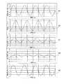
図8は手振れの波形及びその処理結果を時間軸で示した図である。横軸は時間、縦軸は上段より実際の手振れ角度、角速度計4807pの検出する手振れ角速度、HPF後の手振れ角速度、HPF後の角速度出力を積分した積分角度、実際の手振れ角度と積分角度の差である補正残りである。
FIG. 8 is a diagram showing a camera shake waveform and its processing result on a time axis. The horizontal axis represents time, the vertical axis represents the actual camera shake angle from the top, the camera shake angular velocity detected by the
波形801は、実際の手振れの下限周波数である1Hzの振れ角度である。そして、その振れが入力されることで角速度計4807pが検出する角速度を、波形802で示している。ここで実際の角速度計4807pの出力にはDCバイアス成分や長期ドリフト成分が重畳しているので、前述した様に“1Hz折点1次HPF処理”により上記ノイズ成分を減衰させると、波形803となる。
A
波形803は波形802に比べて振幅が半減し、位相も45度進んでしまう。これは前述した様に手振れ下限周波数である1Hzの波形を“1Hz折点1次HPF処理”したことによる影響である。そして、この波形803を前述した様に“1Hz折点1階積分処理”を行うと、波形804となる。ここでも同様の理由で振幅の半減と位相のずれが生じ、実際の振れ角度波形801と比較すると振幅が大きく減衰し、位相も90度進んでしまう。位相がこのように90度進むのは、1次HPFで45度進み、且つ1階積分時に45度進むためにそれらの合計として位相が90度進むことによる。
The
波形805は実際の振れ角度波形801から演算で求めた積分角度の差であり、補正残りに相当するが、その振幅は実際の振れ角度波形801の振幅と殆ど差が無い。即ち、この周波数の振れに関しては画像振れ補正は殆ど出来ない。
A
同様の波形を、今度は“0.1Hz折点1次HPF”及び“0.1Hz折点1階積分処理”した場合を図9に示す。図9においても、横軸は時間、縦軸は上段より実際の手振れ角度、角速度計4807pの検出する手振れ角速度、HPF後の手振れ角速度、HPF後の角速度出力を積分した積分角度、実際の手振れ角度と積分角度の差である補正残りである。
波形901は、実際の振れの下限周波数である1Hzの振れ角度である。そして、その振れが入力される事で角速度計4807pが検出する角速度を、波形902で示している。ここで、実際の角速度計4807pの出力にはDCバイアス成分や長期ドリフト成分が重畳しているので、前述した様に“0.1Hz折点1次HPF処理”により上記ノイズ成分を減衰させると、波形903となる。
FIG. 9 shows a case where the same waveform is subjected to “0.1 Hz break point primary HPF” and “0.1 Hz break point first-order integration processing” this time. Also in FIG. 9, the horizontal axis represents time, the vertical axis represents the actual camera shake angle from the top, the camera shake angular velocity detected by the
A
波形903は波形902に比べても振幅変化は少なく、位相も5度の進みで収まっている。これは前述した様に手振れ下限周波数である1Hzの波形に対して十分低い周波数である“0.1Hz折点1次HPF”で角速度信号を処理したことによる。そして、この波形903を前述した様に“0.1Hz折点1階積分処理”を行うと、波形904となる。ここでも同様の理由で振幅の減衰は少なく、実際の振れ角度波形901と比較すると、位相も10度の進みで収まっている。このように位相が10度進むのは、1階HPFで5度進み、且つ積分時に5度進むためにそれらの合計として位相が10度進むことによる。
The
波形905は実際の振れ角度波形901から演算で求めた積分角度の差であり、補正残りに相当する。その補正残りの振幅は実際の振れ角度波形901の振幅の約1/4に減衰している。即ち、HPF及び積分を手振れ下限周波数より十分低い周波数帯域より処理することで、画像振れ補正の効果を得ることが出来る。
A
図3に戻って、HPF積分フィルタ301の出力(角度信号θ)は敏感度調整部303に入力される。敏感度調整部303は、フォーカスエンコーダやズームエンコーダよりレンズCPU4808に入力されるズーム、フォーカス情報302およびそれらより求まる撮影倍率に基づいてHPF積分フィルタ301の出力を増幅し、角度振れ補正目標値にする。これはレンズのフォーカスやズームなどの光学状態の変化により振れ補正部4806の振れ補正ストロークに対するカメラ像面での振れ補正敏感度が変化することを補正するためである。
Returning to FIG. 3, the output (angle signal θ) of the
レンズCPU4808は、求まった角度振れ補正目標値を駆動部4809に出力し、振れ補正部4806を駆動することで画像振れ補正を行わせる。
The
以上が、従来行われている角度振れ補正の概略構成である。 The above is the schematic configuration of the angular shake correction performed conventionally.
これに対し、本発明の実施例1においては、角度振れ補正目標値に、後述する平行振れ補正目標値を加算して、振れ補正部4806を駆動するようにしている。
On the other hand, in
図10は、振れ補正処理全体の周波数特性を示す図であり、横軸は周波数、縦軸は手振れ角度に対する振れ補正部4806の補正動作の比をデシベル表示で示した利得およびその位相を示す。尚、図6及び図7では、手振れ角速度に対するその積分値の周波数特性の為に手振れ周波数帯域404において利得は周波数に比例して減衰し、位相は90度遅れている。これに対し、図10においては、手振れ角度に対する角度振れ補正目標値(角速度計4807pで検出された振れを演算で求めた振れ角度)の周波数特性であり、角度と角度の比較になるので、手振れ周波数帯域では利得は略一定で、位相も略ゼロとなる。
FIG. 10 is a diagram illustrating the frequency characteristics of the overall shake correction process, where the horizontal axis represents frequency, and the vertical axis represents the gain and phase thereof, which shows the ratio of the correction operation of the
図10において、波形1001において低周波領域(0.1Hz近辺より低い周波数)が減衰しているのは、前述した“0.1Hz折点1次HPF”及び“0.1Hz折点1階積分処理”による。
In FIG. 10, the low-frequency region (frequency lower than near 0.1 Hz) is attenuated in the
前述した様に図6及び図7とは比較の対象が異なるので(図6及び図7では、角度と角速度、図10では角度と角度)、図10の積分処理は0.1Hz以下を減衰させる、HPFと同様な波形となる。また、波形1001において高周波領域(100Hz近辺より高い周波数)が減衰しているのは、振れ補正部4806のメカニカルな応答特性による。
As described above, since the object of comparison is different from FIGS. 6 and 7 (the angle and the angular velocity in FIGS. 6 and 7 and the angle and the angle in FIG. 10), the integration process in FIG. 10 attenuates 0.1 Hz or less. The waveform is similar to that of HPF. Further, the high frequency region (frequency higher than around 100 Hz) is attenuated in the
このように手振れ補正帯域は、HPF、積分処理とメカニカルな応答により設定され、矢印404で示す手振れ帯域の画像振れ補正を行っている。前述した様にHPF、積分処理の折点が手振れ周波数帯域に近い場合ばかりでなく、メカニカルな応答特性がよくない場合(例えば10Hz以上は応答しないような振れ補正部)にも、精度よい画像振れ補正は行えない。そのため、手振れ帯域に合わせてHPFや積分の演算処理やメカニカルな応答を高精度に設定している。
As described above, the camera shake correction band is set by HPF, integration processing, and mechanical response, and image shake correction of the camera shake band indicated by the
図3に戻って、次に、平行振れ補正の構成について説明する。
角速度計4807pの出力はレンズCPU4808に取り込まれる。そして、その出力はHPF積分フィルタ310に入力され、HPF(ハイパスフィルタ或いは高域透過フィルタ)でDC成分をカットされた後に、積分されて角速度出力ωは角度出力θに変換される。尚、HPF積分フィルタ310における積分折点は、HPF積分フィルタ301とは異なっており、その理由は後述する。
Returning to FIG. 3, the configuration of the parallel shake correction will be described next.
The output of the
HPF積分フィルタ310の出力は利得調整フィルタ(以下、利得調整部)311に入力される。この利得調整部311の役割についても後述する。利得調整部311の出力は後述する出力補正部309により補正され、平行振れ補正目標値とされて、前述した角度振れ補正目標値に加算される。
The output of the
また、上記処理と同時に、角速度計4807pの出力はHPF位相調整フィルタ(以下、HPF位相調整部)304に入力され、角速度計4807pの出力に重畳するDC成分をカットされると共にその信号の位相調整が行われる。この時のHPF折点および位相調整に関する詳細は後述する。HPF位相調整部304の出力は帯域透過手段である角速度計BPF部(バンドパスフィルタ或いは帯域透過フィルタ)306で所定帯域の周波数成分のみ抽出される。
Simultaneously with the above processing, the output of the
加速度計101pの出力はHPF積分フィルタ305に入力され、加速度計101pに重畳するDC成分がカットされると共に1階積分して速度Vに変換される。この時のHPFおよび積分折点に関する詳細は後述する。HPF積分フィルタ305の出力は帯域透過手段である加速度計BPF部(バンドパスフィルタ或いは帯域透過フィルタ)307で所定帯域の周波数成分のみ抽出される。
The output of the
角速度計BPF部306及び加速度計BPF部307の出力は、比較部308で比較され、利得調整部311の出力を補正する補正値(補正係数)が算出される。
The outputs of the angular velocity
出力補正部309にはズーム、フォーカス情報302も入力されており、ズーム、フォーカス情報302より撮影倍率を演算し、求められた撮影倍率及び前述した補正値に基づいて利得調整部311の出力を補正して、平行振れ補正目標値にする。求められた平行振れ補正目標値は前述した角度振れ補正目標値に加算され、駆動部4809に出力される。これにより、振れ補正部4806が駆動部4809により駆動され、角度振れと平行振れの両者の画像振れが補正されることになる。
The zoom and focus
以上において、先ず比較部308から出力される補正値について説明する。
The correction value output from the
図11はカメラに加わる角度振れ4803pと平行振れ101pbを示した図である。撮影レンズ4801内の撮像光学系の主点位置における平行振れY(101pb)と角度振れθ(4803p)と回転中心O(1102p)を定めた場合の回転半径L(1101p)の関係は、以下の(1),(2)式にて表せる。
FIG. 11 is a view showing
Y=Lθ ………………(1)
V=Lω ………………(2)
尚、回転半径L(1101p)は、回転中心1102pから加速度計101pまでの距離である。
Y = Lθ ……………… (1)
V = Lω (2)
The rotation radius L (1101p) is a distance from the
ここで、(1)式は、加速度計101pの出力を2階積分して変位Yを求め、又角速度計4807pの出力を1階積分して角度θを求めた場合の回転半径Lである。(2)式は、加速度計101pの出力を1階積分して速度Vを求め、又角速度計4807pの出力より角速度ωを求めた場合の回転半径Lである。これら式(1),(2)いずれの方法でも回転半径Lを求めることができる。
Here, the expression (1) is the radius of rotation L when the output of the
撮像光学系の主点の位置における平行振れYと撮像光学系の振れ角度θ及び撮像光学系の焦点距離fと撮影倍率βより撮像面に生ずる振れδは、以下の式(3)で求められる。 From the parallel shake Y at the position of the principal point of the image pickup optical system, the shake angle θ of the image pickup optical system, the focal length f of the image pickup optical system, and the shooting magnification β, the shake δ generated on the image pickup surface is obtained by the following equation (3). .
δ=(1+β)fθ+βY ………………(3)
ここで、右辺第1項のf,βは撮像光学系のズーム、フォーカス及びそれにより得られる撮影倍率βや焦点距離情報fより求まり、振れ角度θは角速度計4807pの積分結果より求まる。よって、その情報に応じて、図3を用いて説明したように角度振れ補正を行うことができる。
δ = (1 + β) fθ + βY (3)
Here, f and β in the first term on the right side are obtained from the zoom and focus of the image pickup optical system and the imaging magnification β obtained thereby and focal length information f, and the shake angle θ is obtained from the integration result of the
また、右辺第2項に関しては、加速度計101pの2階積分値Yとズーム、フォーカス、及びそれにより得られる撮影倍率βにより求まるので、その情報に応じて、図3を用いて説明したように平行振れ補正を行うことが出来る。
Further, the second term on the right side is obtained from the second-order integral value Y of the
しかし、本実施例1においては、式(3)を、以下の式(4)の様に書き直した振れδに対して画像振れ補正を行っている。 However, in the first embodiment, image blur correction is performed on the shake δ rewritten from Equation (3) as in Equation (4) below.
δ=(1+β)fθ+βLθ ………………(4)
即ち、平行振れに関しては、加速度計101pより直接求まる平行振れ変位Yを用いるのではない。一旦式(1)或いは式(2)で求まる回転半径Lを求め、この回転半径Lと角速度計4807pの出力の積分結果(θ)とズーム、フォーカス及びそれにより得られる撮影倍率βにより補正している。尚、式(4)の右辺第1項が角度振れ補正目標値、右辺第2項が平行振れ補正目標値である。
δ = (1 + β) fθ + βLθ (4)
That is, for the parallel shake, the parallel shake displacement Y obtained directly from the
ここで、加速度計101pは撮像光学系のレンズ主点位置に配置されており、回転半径L(1101p)は回転中心1102pから撮像光学系のレンズ主点位置までの距離に等しい。加速度計101pの出力を2階積分すれば値Yが求まるので、式(3)を利用して平行振れ補正を行えば良いのに、式(4)を用いて平行振れ補正を行う理由を以下に説明する。
Here, the
図12は加速度計101pの信号検出系を示すブロック図であり、図11のように回転中心1102pを中心とした振れ角度θの入力時におけるレンズ主点位置の平行振れ変位Y(101pb)の関係を示している。
FIG. 12 is a block diagram showing a signal detection system of the
今、振れ角度θが入力されると、加速度計101pはその傾きによる重力成分の変動も検出する。そして、振れ角度θが大きくない範囲では重力変動により出力される重力加速度α1(回路部1201の出力)は振れ角度θに比例する。
Now, when the deflection angle θ is input, the
また、振れ角度θに、図11の回転半径L(1101p)を乗じた結果が平行振れ変位Y’(回路部1202の出力)であり、この平行振れ変位Y’を回路部1203にて2階微分した平行振れ加速度α2を加速度計101pは出力する。
Further, the result of multiplying the deflection angle θ by the rotation radius L (1101p) in FIG. 11 is a parallel deflection displacement Y ′ (output of the circuit unit 1202). The
更に、加速度計101pの出力にはノイズも重畳している。ノイズの種類は周波数によらず一定のノイズや周波数に関係するノイズなどがあるが、ここでは周波数に依存しないノイズであり、且つ振れ角度θに比例するノイズとして取り扱うものとする。ここではノイズ用の回路部1204がノイズ加速度α3を出力する。
Furthermore, noise is also superimposed on the output of the
上記の各加速度α1,α2,α3の合計が加速度計101pの出力となり、これが回路部1205により2階積分され、平行振れ変位Yが得られる。
The sum of the accelerations α1, α2, and α3 is the output of the
今、重力加速度比例項をG、回転半径をL、ノイズ比例項をk、角周波数をωとすると、図12の信号検出系は、以下の式(5)で表せる。

右辺の第1項は加速度出力と重力加速度出力の項であり、第2項はノイズ項である。 The first term on the right side is a term for acceleration output and gravity acceleration output, and the second term is a noise term.
ここで、加速度出力と重力加速度出力は共に振れ角度θの位相と関連しており、ノイズに関しては振れ角度θの位相と関連していないので、式(5)の右辺は2つの項に分けて示しているが、簡略化の為に各項の位相を無視すると以下の式(6)となる。
即ち、平行振れの変位は式(7)の等式(式(6)の結果がゼロになる各周波数)が成り立つ各周波数を境に低周波側は重力加速度とノイズが支配的になり、高周波側でのみ正確な平行振れの変位が計測できる。 That is, the displacement of the parallel shake is dominated by gravitational acceleration and noise on the low frequency side at each frequency where the equation (7) (the frequency at which the result of equation (6) becomes zero) holds. Accurate translational displacement can be measured only on the side.
今までの計測結果などより、仮に回転半径L等の量を当てはめた場合の式(6)のボード線図を、図13に示す。図13において、横軸は周波数、縦軸は入力振れ角度θに対する加速度計101pが検出した平行振れ変位Yの利得であり、スケールは「倍」、即ち1倍の時は入力振れ角度θに対して正確に平行振れYを求められている事を示す。
FIG. 13 shows a Bode diagram of Expression (6) when an amount such as the rotation radius L is applied based on the measurement results so far. In FIG. 13, the horizontal axis represents the frequency, and the vertical axis represents the gain of the parallel shake displacement Y detected by the
ここで、利得1301が1.3Hzで極めて小さくなっているのは、加速度計101pが検出する平行振れ加速度が重力加速度とノイズで相殺されている為である。そして、それより低い周波数帯域では低周波になる程加速度計出力が大きくなっており、これは重力加速度やノイズが支配項になる為である。
Here, the reason why the
一方、矢印1302で示すように、この周波数より高周波側では加速度計101pの出力の信頼性は高くなっている。
On the other hand, as indicated by an
今、手振れの帯域は矢印404で示す様に1Hzから10Hzであり、既に重力加速度やノイズの影響がある帯域になっているため、加速度計101pを用いて平行振れを検出することが出来ない。
Now, the hand shake band is from 1 Hz to 10 Hz as indicated by the
そこで、矢印1302で示す加速度計101pの信頼できる帯域を用いて平行振れを検出する事を考えると、式(3)の代わりに式(4)を用いる。つまり、加速度出力1階積分値と角速度出力の比較、或いは加速度出力2階積分値と角速度出力1階積分値の比較により回転半径Lを求め、その回転半径Lと角速度出力より平行振れ成分を求める計算式を採用している。
Therefore, considering that the parallel shake is detected using a reliable band of the
回転半径Lを求める時には、加速度計101pの出力と角速度計4807pの出力を比較(加速度出力を角速度出力で割る)してゆく訳である。しかしここで、加速度出力、角速度出力は図13の矢印1302の帯域のみ抽出して比較することで、上述した重力加速度やノイズの影響を緩和している。
When calculating the turning radius L, the output of the
図3に戻り、角速度計BPF部306及び加速度計BPF部307はともに5Hzのみ抽出する同一の帯域透過フィルタであり、その特性を図14に示す。図14において、横軸は周波数、縦軸は入力されるHPF位相調整部304の出力或いはHPF積分フィルタ305の出力に対する角速度計BPF部306或いは加速度計BPF部の出力比の利得であり、デシベル表示で示している。
Returning to FIG. 3, both the angular velocity
ここで、このフィルタ特性は、5Hzの信号は透過(0デシベルなので、入力信号がそのまま出力される)、0.5Hzの信号や50Hzの信号は減衰(−20デシベルなので、10分の1に減衰)する特性になっている。勿論、抽出する周波数をより特定する為に高次のフィルタを用いてもよい。例えば2次のBPFフィルタを用いて、図15の利得1501の様に、5Hzの信号は透過(0デシベルなので、入力信号がそのまま出力される)、0.5Hzの信号や50Hzの信号は減衰(−40デシベルなので、100分の1に減衰)する特性にしてもよい。
Here, this filter characteristic is that a 5 Hz signal is transmitted (the input signal is output as it is because it is 0 decibels), and a 0.5 Hz signal and a 50 Hz signal are attenuated (−20 decibels because they are −20 decibels). ). Of course, a higher-order filter may be used to further specify the frequency to be extracted. For example, using a second-order BPF filter, a signal of 5 Hz is transmitted (the input signal is output as it is because it is 0 decibels), and a signal of 0.5 Hz and a signal of 50 Hz are attenuated (such as
位相は、5Hzに関しては入力に対する出力位相はゼロであり、その前後においては大きく変化してしまう。しかし、角速度計BPF部306、加速度計BPF部307の互いの出力結果を比較する目的であるので、角速度計BPF部306、加速度計BPF部307ともに位相の変化が同じであれば問題は生じない。
With respect to 5 Hz, the output phase with respect to the input is zero at 5 Hz, and changes greatly before and after that. However,
HPF位相調整部304及びHPF積分フィルタ305の折点に関しても、角速度出力と速度出力を比較するだけであれば、HPF積分フィルタ301と折点を揃える必要は無い。よって、HPF折点はより高周波側(例えば1Hz)に設けてDCカット能力を大きくし、積分に関しても折点をより高周波側(例えば1Hz)に設けることができる。
Regarding the break points of the HPF
一般にHPFや積分は折点が低周波になる程安定までの時間が必要になるが、上記の様に折点を高周波側に設定することで、安定時間を短縮する事ができる。但し、比較精度を向上させる為に、HPF位相調整部304により生じる位相変化とHPF積分フィルタ305で生じる位相変化は同一にしておくことが好ましい。
In general, HPF and integration require time for stabilization as the break point becomes lower in frequency, but by setting the break point on the high frequency side as described above, the stabilization time can be shortened. However, in order to improve the comparison accuracy, it is preferable that the phase change generated by the HPF
図16はHPF積分フィルタ305の特性を示すボード線図であり、このフィルタ処理により加速度計101pの出力(加速度計出力)はHPFでDC成分がカットされ、積分されて速度に変換される。図16において、横軸は周波数、縦軸は加速度出力に対するHPF積分フィルタ305の出力比の利得であり、デシベル表示をしている。
FIG. 16 is a Bode diagram showing the characteristics of the
利得1601は1Hz以下の低い周波数が減衰され、1Hz以上の高い周波数は積分(周波数に比例して利得が減少する)される特性になっている。ここで、次の加速度計BPF部307で抽出すべき5Hzの周波数にのみ着目する。位相1602は5Hzにおいて−90度(積分後の理想位相)に対して矢印1603に示す様に23度遅れが足りていない。そのため、HPF位相調整部304においても同様に5Hzで23度遅れが足りなければ比較上、好都合になる。
The
図17はHPF位相調整部304の特性を示すボード線図であり、このフィルタ処理により角速度計4807pの出力(角速度計出力)はHPFでDC成分がカットされる。図17において、横軸は周波数、縦軸は角速度計出力に対するHPF位相調整部304の出力比の利得であり、デシベル表示をしている。
FIG. 17 is a Bode diagram showing the characteristics of the HPF
利得1701は1Hz以下の低い周波数が減衰される特性になっている。ここで、次の角速度計BPF部306で抽出すべき5Hzの周波数にのみ着目する。位相1702は5Hzにおいて矢印1703に示す様に23度進んでおり、HPF積分フィルタ305で生じる位相変化と同一になっている。これは位相調整として更にHPFを追加した2次のHPFになっている為である。
The
仮に位相調整を省き、HPF積分フィルタ305のHPFと同様に1次のHPFを用いるとする。すると、図18のように、5Hzの位相1802は5Hzにおいて矢印1803に示す様に11度の進みとなり、HPF積分フィルタ305の位相ずれが23度と異なってしまう。そのため、位相調整として更にHPFを追加して、加速度出力のHPF積分フィルタ305による位相ずれと角速度出力のHPF位相調整部304の位相ずれを揃えている。
It is assumed that phase adjustment is omitted and a first-order HPF is used in the same manner as the HPF of the
以上説明したように、図10で示される周波数域(これを第2周波数域とも記す)よりも図14及び図15に示す狭い周波数域(これを第1周波数域とも記す)で角速度計4807pと加速度計101pを比較している。このため、加速度出力に重畳する重力成分やノイズなどの誤差を減衰させた状態で角速度出力と精度よく比較できる。
As described above, the
図3に戻り、比較部308は、角速度計BPF部306の出力ωと加速度計BPF部307の出力Vとを比較して、以下の式(8)
L=V/ω ………………(8)
に示すように回転半径Lを求める。
Returning to FIG. 3, the
L = V / ω ……………… (8)
The rotation radius L is obtained as shown in FIG.
そして、求められた回転半径Lを利用して、上記式(4)で示した計算式で画像振れ補正を行うことになる。そのために比較部308で求められた回転半径Lを利得調整部311の出力に乗じて、出力補正部309にて平行振れ補正目標値とする。
Then, by using the obtained rotation radius L, image blur correction is performed by the calculation formula shown in the above formula (4). For this purpose, the output of the
ここで、式(4)でわかる様に、回転半径Lと手振れの角度出力(振れ角度θ)と撮影倍率β(ズーム、フォーカス情報302より求まる)で、図19のように、HPF積分フィルタ301の出力に直接回転半径Lを補正値として乗じても良さそうである。しかし、そうではなく図3のように平行振れ補正専用にHPF積分フィルタ310及び利得調整部311を設けている点を以下に説明する。
Here, as can be seen from the equation (4), the
まず、図3の利得調整部311の役割を説明する。
First, the role of the
式(8)により回転半径Lは求まるのであるが、厳密には抽出する周波数毎に回転半径Lは異なってくる。図20は、図3の角速度計BPF部306及び加速度計BPF部307の抽出周波数を1Hzから10Hzまで変化させたときの回転半径Lの変化を示している。図20において、横軸は周波数、縦軸は5Hzの回転半径Lを基準とした時の各周波数における回転半径Lの比をデシベル表示している。
Although the turning radius L can be obtained from the equation (8), strictly speaking, the turning radius L differs for each frequency to be extracted. FIG. 20 shows a change in the rotation radius L when the extraction frequency of the angular velocity
回転半径Lの変化2001は周波数に比例して減少しており、これは高周波の振れはカメラと被写体の接点が中心になっており(例えば顔)、周波数が低くなる程に回転中心Lが肘、腰と遠ざかってゆく事を示している。その為に回転半径Lは周波数毎に用意する必要がでてくる。
The
しかしながら、出力補正部309にて角速度積分出力に乗じることが出来る補正値は複数用意できない。よって、利得調整部311では、HPF積分フィルタ310の角速度積分出力(振れ角度θ)側に周波数に応じた図21の特性を持たせ、一定の補正値を乗じても周波数毎に最適な平行振れ補正目標値が得られるようにしている。即ち、補正値として乗じる回転半径Lの変化(周波数依存性)を、乗じられる角速度計4807pの積分出力側で利得調整部311により見かけ上持たせるように調整している。
However, a plurality of correction values that can be multiplied by the angular velocity integrated output by the
図21は利得調整部311のボード線図であり、横軸は周波数、縦軸はHPF積分フィルタ310の出力に対する利得調整部311の出力比のデシベル表示と位相である。
FIG. 21 is a Bode diagram of the
ここで、利得2101は高周波になる程出力がほぼ比例して減衰する特性になっている。例えば一定の補正値として5Hz抽出時の回転半径Lを利得調整部311の出力に出力補正部309が乗じた結果は、HPF積分フィルタ310に対して周波数毎に図20で示すような異なる回転半径Lを乗じた場合に近い結果を得ることができる。つまり、図20に示されるような回転半径Lの周波数依存性を見かけ上持たせることができる。
Here, the
しかしながら、HPF積分フィルタ301とHPF積分フィルタ310の周波数特性が同じ場合には、図21の位相2102を見ると、手振れ帯域404において大きくずれており、例えば1Hzにおいては18度位相が遅れてしまう。そこで、その位相遅れを相殺する為にHPF積分フィルタ310の周波数特性をHPF積分フィルタ301の周波数特性とは異ならせている。
However, when the frequency characteristics of the
前述した様に、HPF積分フィルタ301の折点は、HPF、積分とも0.1Hzに設定して、手振れ下限周波数である1Hzの位相ずれを小さくしている。それに対して、HPF積分フィルタ310の積分折点は0.5Hzに設定している。
As described above, the break point of the
図22はHPF積分フィルタ310のボード線図であり、横軸は周波数、縦軸は角速度計出力に対するHPF積分フィルタ310の出力比のデシベル表示と位相である。
FIG. 22 is a Bode diagram of the
ここで、利得2201は手振れ帯域404では十分な積分特性(周波数に比例して出力が減衰)を得られている。しかし、位相2202は、矢印2203に示す様に、手振れ下限周波数で34度位相遅れが足りない(実際は位相遅れが90度にならなくてはいけないのが、位相が56度しか遅れていない)。
Here, the
しかしながら、HPF積分フィルタ310と利得調整部311の両者と透過した角速度計の信号は、利得調整部311の利得調整による位相遅れがHPF積分フィルタ310の位相遅れ不足分を相殺する。
However, in the angular velocity meter signal transmitted through both the
図23はHPF積分フィルタ310と利得調整部311の両者と透過した特性のボード線図であり、横軸は周波数、縦軸は角速度計出力に対する利得調整部311出力比のデシベル表示と位相である。
FIG. 23 is a Bode diagram of characteristics transmitted through both the
ここで、利得2301は手振れ帯域404では十分な積分特性(周波数に比例して出力が減衰)プラス回転半径の周波数依存を補正する特性が得られており、位相2302も矢印2303に示すように手振れ下限周波数で16度の位相不足で済んでいる。
Here, the
このように、一定の補正値として5Hz抽出時の回転半径Lを利得調整部311の出力に出力補正部309が乗じた結果は、HPF積分フィルタ310に対して周波数毎に図20で示すような異なる回転半径Lを乗じた場合に近い結果を得ることができる。
As described above, the result of the
図3で示したように、角速度計BPF部306と加速度計BPF部307を設けている。そして、図10で示される振れ補正の為の周波数域(第2周波数域)よりも、図14及び15に示す狭い周波数域(第1周波数域)で角速度計4807pと加速度計101pを比較している。その為に、加速度出力に重畳する重力成分やノイズなどの誤差を減衰させた状態で角速度出力と精度よく比較できる。
As shown in FIG. 3, an angular velocity
また、角速度計4807pの出力に基づいて角度振れ補正目標値と平行振れ補正目標値を演算する訳である。しかし、図3で示したように、角度振れ補正目標値はHPF積分フィルタ301を用いて演算し、平行振れ補正目標値はHPF積分フィルタ310を用いて演算している。即ち、角度振れと平行振れで夫々異なる周波数帯域となっており、又、平行振れ補正目標値の演算は利得調整部311を用いることで、角度振れ補正目標値の演算とは異なる周波数特性を設定している。
Further, the angular shake correction target value and the parallel shake correction target value are calculated based on the output of the
ここで、角度振れの補正システムは、角速度計4807p、HPF積分フィルタ301、敏感度調整部303、駆動部4809、振れ補正部4806で構成される。この中で、HPF積分フィルタ301、敏感度調整部303を第1防振制御手段と呼ぶ。また、平行振れの補正システムは、角速度計4807p、HPF積分フィルタ310、利得調整部311、出力補正部309、駆動部4809、振れ補正部4806で構成される。この中で、HPF積分フィルタ310、利得調整部311、出力補正部309を第2防振制御手段と呼ぶ。利得調整部311(周波数帯域変更手段)は、第1防振制御手段と第2防振制御手段の周波数特性を異ならせることによって回転半径L(補正値)に見かけ上周波数依存性を持たせるために第2防振制御手段の周波数特性を変更している。このことで、角度振れの補正精度を劣化させずに、平行振れの補正精度を高めることを可能にしている。
Here, the angular shake correction system includes an
これにより、角度振れと平行振れの夫々を精度よく補正できるようになっている。 Thereby, each of the angular shake and the parallel shake can be corrected with high accuracy.
尚、狭い周波数域(第1周波数域)における角速度出力、加速度出力を抽出する方法は上述したBPF処理に限られない。 Note that the method for extracting the angular velocity output and the acceleration output in a narrow frequency range (first frequency range) is not limited to the BPF process described above.
図24は、比較したい周波数における角速度計4807p、加速度計101pのスペクトルを公知のフーリエ変換法により求め、その結果を比較部308で比較する方式を示している。
FIG. 24 shows a method in which the spectra of the
角速度計フーリエ変換演算部2401、加速度計フーリエ変換演算部2402は夫々角速度計出力、加速度計出力に対して、抽出したい周波数成分を乗じて、その結果を積分することでスペクトルを求めている。そして、加速度計101pのスペクトルは以下の式(9)、角速度計のスペクトルは以下の式(10)で表される(後述の位相説明も考慮して、ここでは複素正弦波で表現しない)。
ここで、fは抽出したい周波数であり、例えばf=5Hz、nは整数であり、例えばn=1である。又、G(t)、H(t)は抽出する周波数における夫々速度、角速度のサンプリングタイミング毎の出力である。この式は抽出したい周波数の整数周期分における正弦波と余弦波の定積分値の合成を示している。 Here, f is a frequency to be extracted, for example, f = 5 Hz, and n is an integer, for example, n = 1. G (t) and H (t) are outputs at the sampling timing of the velocity and angular velocity, respectively, at the frequency to be extracted. This formula shows the synthesis of the definite integral values of the sine wave and cosine wave for the integer period of the frequency to be extracted.
式(9),(10)の結果を使って速度および角速度を求め、式(8)により回転半径Lを求める事ができる。 Using the results of the equations (9) and (10), the velocity and the angular velocity are obtained, and the turning radius L can be obtained by the equation (8).
図3では、加速度計101pの積分出力(速度)の中で抽出したい周波数成分のみを透過するBPFを用いて、その周波数成分の速度の大きさを求めている。同様に、角速度計4807pの出力の中で抽出したい周波数成分のみを透過するBPFを用いて、その周波数成分の速度の大きさを求めている。そして、それらの比較で回転半径Lを求めている。
In FIG. 3, the BPF that transmits only the frequency component to be extracted from the integrated output (speed) of the
図24では、加速度計101pの積分出力(速度)の中で抽出したい周波数成分のスペクトルをフーリエ変換で求め、同様に角速度計4807pの出力の中で周波数成分のスペクトルをフーリエ変換で求めている。そして、それらの比較で回転半径Lを求めている。
In FIG. 24, the spectrum of the frequency component desired to be extracted from the integrated output (velocity) of the
ここで、図24に示したHPF位相調整部304、HPF積分フィルタ305の代わりに、図25や図26に示す様に、HPF積分位相調整部2501,2601や、HPF2階積分フィルタ2502,2602を設ける。そして、角速度計4807pの出力ωを積分して角度θとし、加速度計101pの出力αを2階積分して変位Yとして、以下の式(11)より回転半径Lを求めても良い。
Here, instead of the HPF
L=Y/θ ………………(11)
角速度出力を積分すること及び加速度出力は2階積分することで、高周波成分のノイズの影響を受け難くなる為に安定して回転半径Lを求める事ができる。
L = Y / θ (11)
By integrating the angular velocity output and the acceleration output by second-order integration, it becomes difficult to be affected by the noise of the high frequency component, so that the rotation radius L can be obtained stably.
次に、式(8)或いは式(11)の結果である回転半径Lを実際はどのようにして求めているか説明する。尚、ここでは式(8)の様に角速度ωと速度Vを比較して回転半径Lを求める方法について説明し、式(11)の様に角度θと変位Yの比較も処理としては同様になる為にその説明は省く。 Next, how the turning radius L, which is the result of equation (8) or equation (11), is actually determined will be described. Here, a method for obtaining the rotation radius L by comparing the angular velocity ω and the velocity V as in the equation (8) will be described, and the comparison between the angle θ and the displacement Y as in the equation (11) is similarly performed. Therefore, the explanation is omitted.
まず、BPFを用いる場合、図27のように、HPF位相調整部304の出力波形2701及びHPF積分フィルタ305の出力波形2702を一定周期毎にサンプリングし、その結果を夫々角速度ω1、速度V1とする。尚、図27において、横軸時間、縦軸は夫々BPF後の角速度、及び加速度を積分した速度である。
First, when using BPF, as shown in FIG. 27, the
図27の矢印2703,2704,2705,2706,2707,2708,2709は夫々サンプリング周期である。この周期間の角速度の差ωnを、矢印2710(ω1),2711(ω2),2712(ω3),2713(ω4),2714(ω5),2715(ω6),2716(ω7)で示す。同様に、この周期間の速度の差をVnとして、矢印2717(V1),2718(V2),2719(V3),2720(V4),2721(V5),2722(V6),2723(V7)で示す。
The
サンプリング周期としては抽出周波数の周期の半分を設定しており、例えば抽出周波数を5Hzとした場合には、0.1秒となる。そして、周期2703で得られた角速度の差ω1及び速度の差V1より式(8)を用いて回転半径L1を求める。次のサンプルからも同様に、角速度ω2、速度V2より式(8)を用いて回転半径L2を求める。
As the sampling period, half the period of the extraction frequency is set. For example, when the extraction frequency is 5 Hz, the sampling period is 0.1 second. Then, the rotational radius L1 is obtained using the equation (8) from the angular velocity difference ω1 and the velocity difference V1 obtained in the
この様にして順番に回転半径Lを求めると同時に、求めた回転半径Lを平均することで、安定した回転半径Lを求める。即ち、サンプリングの回数をnとすると、以下の式(12)に示すようにして平均値を求めてゆく。
この様にして求めた回転半径Lを用いて、上記式(4)を用いて像面上での振れ量を計算し、画像振れ補正を行う。即ち、式(12)で求めた回転半径Lを、図3の出力補正部309に補正値として出力する。
Using the rotation radius L obtained in this way, the amount of shake on the image plane is calculated using the above equation (4), and image shake correction is performed. That is, the rotation radius L obtained by Expression (12) is output as a correction value to the
周期毎に回転半径Li(例えばL1)を用いて、その瞬間の像面振れ量を式(4)で求めて、その瞬間での画像振れ補正を行うのではなく、各周期で求めた回転中心Lの平均値を求め、その結果より式(4)で像面での振れ量を求めている理由を以下に説明する。 Using the rotation radius Li (for example, L1) for each period, the image center shake amount at that moment is obtained by the equation (4), and the image center at that moment is not corrected, but the rotation center obtained at each cycle. The reason why the average value of L is obtained and the amount of shake on the image plane is obtained from the result by equation (4) will be described below.
角速度出力、加速度出力にはもともとノイズ成分が多く含まれており、そのため、1周期で求めた回転半径Lの信頼性は低くなる。そこで、回転半径Lを平均化することで安定した回転半径Lを得ることができる。 The angular velocity output and the acceleration output originally contain a lot of noise components, and therefore the reliability of the rotation radius L obtained in one cycle is low. Therefore, by averaging the turning radius L, a stable turning radius L can be obtained.
上記は周期毎にサンプリングした結果で回転半径Lを求める方法であるが、その方法には限定されず、例えば波形のピークを利用する方法や、波形の面積を利用する方法がある。 The above is a method for obtaining the rotation radius L based on the result of sampling every period, but is not limited to this method, and there are, for example, a method using the peak of the waveform and a method using the area of the waveform.
図28は波形のピークを利用する方法であり、横軸は時間、縦軸は夫々BPF後の角速度、及び加速度を積分した速度である。 FIG. 28 shows a method using the peak of the waveform, where the horizontal axis represents time, and the vertical axis represents the angular velocity after BPF and the velocity obtained by integrating the acceleration.
矢印2801,2802,2803は夫々サンプリング周期であり、この周期間の極大値と極小値の角速度の差ωnを、矢印2804(ω1),2805(ω2),2806(ω3)で示す。同様に、この周期間の速度の差をVnとして、矢印2807(V1),2808(V2),2809(V3)で示す。
サンプリング周期としては抽出周波数の周期の1周期分を設定しており、例えば抽出周波数を5Hzとした場合には、0.2秒となる。そして、周期2801で得られた角速度の差ω1及び速度の差V1より式(8)を用いて回転半径L1を求める。次のサンプルからも同様に、角速度ω2、速度V2より式(8)を用いて回転半径L2を求める。
As the sampling period, one period of the extraction frequency is set. For example, when the extraction frequency is 5 Hz, the sampling frequency is 0.2 seconds. Then, the rotational radius L1 is obtained from the angular velocity difference ω1 and the velocity difference V1 obtained in the
この様にして順番に回転半径Lを求めると同時に、求めた回転半径Lを式(12)で平均することで、安定した回転半径Lを求める。 In this way, the rotation radius L is obtained in order, and at the same time, the obtained rotation radius L is averaged by equation (12) to obtain a stable rotation radius L.
図29は波形の面積を利用する方法であり、横軸は時間、縦軸は夫々BPF後の角速度、及び加速度を積分した速度である。 FIG. 29 shows a method using the area of the waveform, where the horizontal axis represents time, and the vertical axis represents the angular velocity after BPF and the velocity obtained by integrating the acceleration.
図29において、2901は角速度出力(HPF位相調整部304の出力)を絶対値化した波形であり、2902は速度出力(HPF積分フィルタ305の出力)を絶対値化した波形である。矢印2903はサンプリング期間であり、例えばカメラの主電源を入れてから撮影を開始するまでの期間である。或いは、カメラのレリーズボタン4804aを半押ししてから撮影を開始するまで、カメラの姿勢が安定してから被写体への合焦が完了するまで、或いは被写体距離が判明するまでの期間である。そして、斜線で示すこの期間内の波形2901の面積2904と波形2902の面積2905を求める。
In FIG. 29, 2901 is a waveform obtained by converting the angular velocity output (output of the HPF phase adjustment unit 304) into an absolute value, and 2902 is a waveform obtained by converting the velocity output (output of the HPF integration filter 305) into an absolute value. An
面積2904をSω、面積2905をSvとすると、それらは以下の式(13),(14)で表すことができる。
ここで、Tはサンプリング期間2903である。このため、回転半径Lは以下の式(15)で求められる。これは回転半径Lの平均値を求めていることになる。
この様にサンプリング期間中の面積を用いることで、ノイズや瞬間的な外乱に影響されない安定した回転半径Lを求める事ができる。 By using the area during the sampling period in this way, a stable turning radius L that is not affected by noise or instantaneous disturbance can be obtained.
次に、BPFではなく、図24で示した様にフーリエ変換でスペクトルを求め、その結果から回転半径Lを得る方式について説明する。 Next, a method of obtaining a rotation radius L from the result of obtaining a spectrum by Fourier transform as shown in FIG. 24 instead of BPF will be described.
式(9),(10)を用いて加速度出力を積分した速度のスペクトルVF、角速度のスペクトルωFを求め、以下の式(16)で回転半径LFを求める。
ここで、式(9),(10)におけるnを例えばfとして、抽出したい周波数の1周期分に設定する。即ち、図28におけるサンプリング期間2801,2802,2803毎に各スペクトルVF,ωFに基づいて回転半径LFを算出する。そして、各々の期間で求められた回転半径LFを平均して、図24の出力補正部309に補正値として出力する。
Here, n in the formulas (9) and (10) is set as, for example, f, and is set for one cycle of the frequency to be extracted. That is, the rotation radius LF is calculated based on the spectra VF and ωF for each of the
別の方法として、図29に示してあるサンプリング期間2903の間のスペクトルVF,ωFを式(9),(10)で求め、その結果に基づいて式(16)で回転半径LFを求めてもよい。この場合には回転半径LFの平均化処理は行わないが、スペクトルVF,ωFを求める期間が長くなる為に、結果としてスペクトルVF,ωFは平均化され、安定した回転半径Lを得ることができる。
As another method, the spectra VF and ωF during the
図30は、以上説明した角度振れ補正及び平行振れ補正のタイミングチャートであり、横軸は時間、各々の縦軸は軸上がHi、軸底がLoである。 FIG. 30 is a timing chart of the angular shake correction and the parallel shake correction described above, where the horizontal axis is time, each vertical axis is Hi on the axis, and Lo is the axis bottom.
図30において、3001はカメラ4804のメインスイッチの状態(主電源の状態)を示し、Hiがオン、Loがオフである。3002はレリーズボタン4804aの半押しでオンするスイッチS1の状態を示し、Hiがオン(半押し)、Loがオフ(半押し解除)である。3003はレリーズボタン4804aを更に押し込んだ時にオンするスイッチS2の状態を示し、Hiがオン(押し切り)、Loがオフ(半押し状態)である。
In FIG. 30, 3001 shows the state of the main switch (main power supply state) of the
3004はクイックリターンミラー、シャッタ、絞り駆動の各動作、つまり図1の撮像素子4805に被写体情報を蓄積する為に最適な撮影光路を確保する動作を示し、Hiで動作、Loで動作停止である。3005は撮像素子4805に被写体情報を蓄積する露光動作の状態を示し、Hiで動作、Loで蓄積リセットである。尚、実際には露光動作以外でも被写体情報を撮像素子4805に蓄積し、その画像をカメラの背面モニターなどに表示する動作もあるが、図30では含めていない。
3006は不図示のAFセンサで撮影レンズ4801の撮像光学系を通した被写体光束の焦点状態を検出する焦点検出動作の状態を示し、Hiで焦点状態検出、Loで非動作である。3007は不図示のAFセンサの信号を受けて撮影レンズ4801の撮像光学系の一部或いは全てのレンズを繰出して焦点状態を調節するAFレンズ駆動の状態を示し、Hiで調節動作、Loは駆動停止中である。3008は角速度計4807p、加速度計101pの検出動作の状態を示し、Hiで動作中、Loは非動作である。
3009は角速度出力、加速度出力より回転半径Lを算出する回転半径検出動作の状態を示し、Hiは算出期間、Loは算出中止期間である。3010は振れ補正部4806を用いて角度振れを補正する角度振れ補正動作の状態を示し、Hiが補正期間、Loが非補正期間である。3011は振れ補正部4806を用いて平行振れを補正する平行振れ補正動作の状態を示し、Hiが補正期間、Loが非補正期間である。
以上において、時刻t1に主電源がオンされた時のその後の各要素の動作を、図30のタイミングチャートを用いて説明する。 The operation of each element after the main power supply is turned on at time t1 will be described with reference to the timing chart of FIG.
時刻t2でレリーズボタン4804aが半押し(スイッチS1がオン)される(3002)。それに同期して不図示のAFセンサが焦点状態の検出を始める(3006)。又、角速度計4807p、加速度計101pが動作を始める(3008)。尚、撮影者によりレリーズボタン4804aが半押しされていると云う事は、カメラは被写体を狙って安定状態(カメラに大きな揺れが加わっていない状態)であるので、加速度計101p、角速度計4807pの安定した演算が行える。そこで、加速度計101p、角速度計4807pの出力に基づいて回転半径Lの演算を始める(3009)。又、角度振れ補正を始める(3010)。
At time t2,
時刻t3で、不図示のAFセンサの信号により撮像光学系の焦点状態が求まると、撮像光学系の一部或いは全部を繰出して焦点状態の調節を行う(3007)。この時、回転半径Lを求める演算を中止する(3009)。これは撮像光学系が駆動中はその駆動振動が加速度計101pに加わり、正確な振れ検出が行えない為である。
When the focus state of the image pickup optical system is obtained from the signal of the AF sensor (not shown) at time t3, the focus state is adjusted by extending a part or all of the image pickup optical system (3007). At this time, the calculation for obtaining the rotation radius L is stopped (3009). This is because the drive vibration is applied to the
図3などで説明したように、加速度計101pの出力はある周波数(例えば5Hz)のみ抽出している。そのため、上述の駆動ノイズはフィルタで減衰されて問題なくなる筈であるが、実際にはレンズ駆動の振動が大きすぎて加速度計101pの出力が飽和してしまう場合もある。加速度出力が飽和してしまうと、全ての周波数帯域の振動(振れも含む)が検出できなくなり、加速度計101pはエラー信号しか出力しない。そのエラー信号で回転半径Lを求めると誤った平行振れ補正を行う可能性がある。
As described with reference to FIG. 3 and the like, only a certain frequency (for example, 5 Hz) is extracted from the output of the
そこで、焦点調節の為のレンズ(フォーカスレンズ)駆動中には回転半径Lの演算を中止している。勿論、加速度検出範囲を広い加速度計(大きな加速度も検出可能な加速度計)を用いてレンズ駆動の振動では飽和が起きないようにすれば良いのである。しかし、そのように検出範囲の広い加速度計は手振れのように微小な加速度に関する精度が低い為に安定した回転半径検出が出来ない。そこで、加速度検出範囲は多少犠牲にしても手振れ検出精度の高い加速度計を用い、外乱振動入力時の加速度計信号は回転半径演算に用いないようにしている。 Therefore, the calculation of the rotation radius L is stopped while the lens for focus adjustment (focus lens) is being driven. Of course, it is only necessary to use an accelerometer with a wide acceleration detection range (an accelerometer capable of detecting a large acceleration) so that saturation does not occur in lens-driven vibration. However, such an accelerometer with a wide detection range cannot detect a stable turning radius due to low accuracy related to minute acceleration such as camera shake. Therefore, an accelerometer with high hand shake detection accuracy is used even if the acceleration detection range is somewhat sacrificed, and the accelerometer signal at the time of disturbance vibration input is not used for the rotation radius calculation.
時刻t4では、レンズが目標とする位置に到達し、その駆動を停止する(3007)。また、それに同期して不図示のAFセンサが再度焦点状態の検出を行い、所望の焦点状態になったか否かを確認する(3006)。 At time t4, the lens reaches the target position and stops driving (3007). In synchronism with this, an AF sensor (not shown) detects the focus state again, and confirms whether or not the desired focus state has been reached (3006).
時刻t5では、AFが所望の焦点状態になった事が確認出来たので、焦点状態検出を終了する(3006)。ここで、所望の焦点状態になっていない事が判明した場合には再度レンズを駆動して焦点状態の再調節を繰り返す。又、所望の焦点状態が確認できた場合には回転半径の算出動作を再開する(3009)。これは、時刻t5以降でレンズ駆動による外乱振動が加速度計に加わる虞がない為である。尚、時刻t5でレンズの駆動が停止した時点で、その繰出し量から被写体距離を求める。そして、ズーム状態との関連より撮影倍率を求めて平行振れ補正目標値に生かす。 At time t5, since it has been confirmed that the AF has reached the desired focus state, focus state detection ends (3006). If it is found that the desired focus state is not obtained, the lens is driven again and the focus state is readjusted repeatedly. If the desired focus state can be confirmed, the operation for calculating the radius of rotation is resumed (3009). This is because there is no possibility that disturbance vibration due to lens driving is applied to the accelerometer after time t5. When the lens driving is stopped at time t5, the subject distance is obtained from the amount of extension. Then, the imaging magnification is obtained from the relationship with the zoom state and used as the parallel shake correction target value.
時刻t6では、レリーズボタン4804aの押し切り動作によりスイッチS2がオンする(3003)。それと同期して時刻t9までの間に撮影レンズ4801内の絞りやカメラ4804のクイックリターンミラーのアップ、シャッタ開が動作する(3004)。又、回転半径Lの算出を停止する(3009)。これは、絞りの絞り込みやクイックリターンミラーのアップ、シャッタ開の動作に伴う振動により前述した様に加速度計101pが飽和してしまい、回転半径Lの演算精度を低下させてしまうのを防ぐ為である。
At time t6, the switch S2 is turned on by pressing the
時刻t7では、露光を開始する(3005)。それと同期して平行振れ補正を開始する(3011)。尚、平行振れ補正を行う時の回転半径Lは時刻t2からt3迄の期間の平均値及びt5からt6迄の期間に求めた平均値の更に平均を用いている。 At time t7, exposure is started (3005). In parallel with this, parallel shake correction is started (3011). Note that the rotation radius L when performing parallel shake correction uses the average value of the period from time t2 to t3 and the average of the average value obtained during the period from t5 to t6.
時刻t8では、露光を終了する(3005)。又、平行振れの補正も終了する(3011)。この様に平行振れの補正は露光期間しか行っていない。これは、角度振れの補正に加えて平行振れの補正を行うと、振れ補正部4806の補正ストロークが多く必要となり、振れ補正部4806が大型化して撮影レンズ4801が扱い難くなってしまう為である。その為、露光という短い時間にのみ平行振れ補正を行い、露光終了後は角度振れ補正のみに戻す。
At time t8, the exposure ends (3005). Also, the correction of the parallel shake ends (3011). In this way, the parallel shake is corrected only for the exposure period. This is because if the correction of the parallel shake is performed in addition to the correction of the angular shake, a large correction stroke of the
時刻t8からt9の間には、シャッタ閉や絞りの開放、クイックリターンミラーダウン動作が行われる(3004)。そして、時刻t9迄の間は回転半径Lの算出を停止している(3009)。これも上述した様に、絞りの開放動作やクイックリターンミラーダウン、シャッタ閉の動作に伴う振動により前述した様に加速度計が飽和してしまい、回転半径Lの演算精度を低下させてしまうのを防ぐ為である。 Between time t8 and t9, shutter closing, aperture opening, and quick return mirror down operation are performed (3004). The rotation radius L is not calculated until time t9 (3009). As described above, as described above, the accelerometer is saturated due to vibrations associated with the aperture opening operation, the quick return mirror down operation, and the shutter closing operation, which reduces the calculation accuracy of the rotation radius L. This is to prevent it.
時刻t9では、回転半径Lの算出を再開する(3009)。時刻t10では、レリーズボタン4804aの押し切り(スイッチS2のオン)が解除され、半押し状態になる(3003)。
At time t9, the calculation of the rotation radius L is resumed (3009). At time t10, the
時刻t11では、再びレリーズボタン4804aの押し切り動作によりスイッチS2がオンする(3003)。それと同期して時刻t12までの間に、撮影レンズ4801内の絞りやカメラ4804のクイックリターンミラーアップ、シャッタ開が動作する(3004)。又、回転半径Lの算出を停止する(3009)。
At time t11, the switch S2 is turned on again by pressing the
時刻t12では、露光を開始する(3005)。それと同期して平行振れ補正を開始する(3011)。尚、平行振れ補正を行う時の回転半径Lは、時刻t2からt3迄の期間の平均値、及び、時刻t5からt6迄の期間に求めた平均値、及び、時刻t9からt11迄の期間の平均値の、更に平均を用いている。この様に、回転半径Lはレリーズボタン4804aの半押し(スイッチS1のオン)が継続している間はリセットされず、累積されて平均が求められる。
At time t12, exposure is started (3005). In parallel with this, parallel shake correction is started (3011). Note that the rotation radius L when performing parallel shake correction is the average value during the period from time t2 to t3, the average value obtained during the period from time t5 to t6, and the period from time t9 to t11. The average of the average values is used. Thus, the rotation radius L is not reset while the
時刻t13では、露光を終了する(3005)。又、平行振れの補正も終了する(3011)。時刻t13からt14の間にはシャッタ閉や絞りの開放、クイックリターンミラーダウン動作が行われる(3004)。そして、時刻t14迄の間は回転半径Lの算出を停止している(3009)。 At time t13, the exposure ends (3005). Also, the correction of the parallel shake ends (3011). Between time t13 and t14, shutter closing, aperture opening, and quick return mirror down operation are performed (3004). Until the time t14, the calculation of the rotation radius L is stopped (3009).
時刻t14では、回転半径Lの算出を再開する(3009)。時刻t15では、レリーズボタン4804aの押し切り(スイッチS2のオン)が解除され、半押し(スイッチS1のオン)状態になる(3003)。
At time t14, the calculation of the rotation radius L is resumed (3009). At time t15, the
時刻t16では、レリーズボタン4804aの半押し(スイッチS1のオン)が解除される(3002)。それと同期して回転半径Lの算出を停止する(3009)。また、それまで累積して平均を求めてきた回転半径Lの値をリセットさせる。それはレリーズボタン4804aを再度半押し(スイッチS1がオン)した時点ではカメラの把持の方法などが異なっている可能性もある為、今まで求めた回転半径Lがそのまま平行振れ補正に使えるか否か分からない為である。再度レリーズボタン4804aの半押しがされた時には、新たに回転半径Lを求め直すことになる。
At time t16, the half-press of the
時刻t16から所定時間(例えば4秒)経過後の時刻t17では、角速度計4807p、加速度計101pの動作を停止する(3008)。又、角度振れ補正も停止する(3010)。時刻t15で角速度計4807p、加速度計101pの動作や角度振れ補正を停止しないのは、再度レリーズボタン4804aの半押し(スイッチS1のオン)操作が行われた時に、角度振れ補正を瞬時に対処する為である。
At time t17 after elapse of a predetermined time (for example, 4 seconds) from time t16, the operations of the
時刻t18では、カメラの主電源をオフにする(3001)。 At time t18, the main power supply of the camera is turned off (3001).
上記タイミングチャートには示していないが、回転半径Lはカメラの姿勢が大きく変化した時も演算を停止しており、それまでの回転半径Lの平均に加えないようにしている。カメラのパンニング操作やその他、大きなカメラの姿勢変化の操作が起きると、その時の回転半径はカメラを構えて被写体を狙っている時とは異なるので、その時に求まる回転半径Lは平行振れ補正精度を劣化させる虞がある為である。 Although not shown in the timing chart, the calculation of the rotation radius L is stopped even when the posture of the camera changes greatly, and it is not added to the average of the rotation radius L so far. When a camera panning operation or other large camera posture change operation occurs, the rotation radius at that time is different from that when the camera is held and the subject is aimed at, so the rotation radius L obtained at that time increases the parallel shake correction accuracy. This is because there is a risk of deterioration.
そこで、例えば角速度計4807pの出力が所定時間(例えば0.5秒)所定以上(例えば3deg/s)となった場合にはそれまで求めた回転半径Lをリセットし、角速度計4807pの出力が低くなった時点で新たに回転半径Lを求め直している。同様に、加速度計101pの出力が所定時間(例えば0.5秒)所定変化以上(例えば0.2G)となった場合にはカメラの姿勢が大きく変化したと判定する。そして、それまで求めた回転半径Lをリセットし、加速度計101pの出力変化が小さくなった時点で新たに回転半径Lを求め直している。
Therefore, for example, when the output of the
尚、時刻t2で回転半径Lの検出をはじめてから直ぐに時刻t6でレリーズボタン4804aの押し切りが行われてしまい、回転半径Lの算出が十分に行えない場合もある。そのような時には予め与えられている回転半径Lを用いて平行振れの補正を行う。
Note that the
前述した様に手振れの回転中心は周波数毎に異なり、高周波はカメラの接眼部、低周波は撮影者の腰近傍であり、周波数毎に異なる回転半径を処理する為に図21で示した様な特性の利得調整部311を用いている。
As described above, the rotation center of camera shake is different for each frequency, the high frequency is the eyepiece of the camera, the low frequency is near the photographer's waist, and as shown in FIG. The
ここで、5Hz近傍の振れの回転中心は凡そカメラの接眼部近傍である為に、回転半径Lが不明の時には、図31に示す様に、初期値としてカメラの接眼部から撮像光学系の主点位置までの距離を回転半径3101として設定する。
Here, since the center of rotation of shake near 5 Hz is about the vicinity of the eyepiece of the camera, when the radius of rotation L is unknown, as shown in FIG. Is set as the radius of
尚、ここでカメラの接眼部は矢印3102の位置であるが、その位置における光軸3103との交点を回転中心3104とし、回転中心3104と撮像光学系の主点位置3105迄の距離を回転半径3101としている。これは振れ補正部が補正する方向が光軸3103と直交する方向であるため、その方向の平行振れ成分のみ補正するためである。
Here, the eyepiece of the camera is at the position of the
ここで、時刻t2でレリーズボタン4804aの半押しから直ぐに時刻t6でレリーズボタン4804aの押し切りが行われたとする。この場合は、その初期値を用いて平行振れの補正を行い、時刻t2でレリーズボタン4804aの半押しからt6でレリーズボタン4804aの押し切り迄時間がある場合には算出した回転半径Lを用いる。
Here, it is assumed that the
また、算出した回転半径Lがカメラの把持状態などの影響で大きく変動する場合がある。 例えばカメラを手振れが極めて少ない状態で把持した場合には、手振れが無い為に角速度計の出力は極めて小さい。この様な時に加速度計101pを積分した速度出力にDCバイアス成分などが重畳し、所定の出力があった場合には、式(8)で求まる回転半径Lは極めて大きな値になってしまう。このような時は算出した回転半径Lは用いず、回転半径初期値を用いて平行振れ補正を行う。即ち、角速度出力が極めて小さい場合や、求めた回転半径が所定以上(例えば撮像光学系の主点位置から撮影者の腰までの距離以上)の場合には、回転半径Lとして初期値を用いて平行振れ補正を行う。
Further, the calculated turning radius L may vary greatly due to the influence of the gripping state of the camera. For example, when the camera is gripped with very little camera shake, the output of the angular velocity meter is extremely small because there is no camera shake. In such a case, when a DC bias component or the like is superimposed on the speed output obtained by integrating the
図32は、以上の構成を説明するフローチャートであり、このフローはカメラの主電源オンでスタートする。 FIG. 32 is a flowchart for explaining the above configuration, and this flow starts when the main power of the camera is turned on.
尚、本発明の主要な構成を分かり易く説明する為に、カメラに設けられる多用な制御動作(例えば、バッテリチェックや測光、測距、AFの為のレンズ駆動、ストロボ充電、そして撮影の為の操作、動作など)は省いている。また、以下のフローにおいては、カメラの角度振れ4803pを角速度計4807pで、平行振れ101pbを加速度計101pで、それぞれ検出する場合を例に説明を進める。しかし、カメラの角度振れ4803yを角速度計4807yで、平行振れ101ybを加速度計101yで、それぞれ検出する場合も同様のフローになる。更に、このフローはいかなるステップへ進んでいようと、カメラの主電源オフで終了するものとする。
In order to explain the main configuration of the present invention in an easy-to-understand manner, various control operations (for example, battery check, photometry, distance measurement, lens driving for AF, strobe charging, and photographing are provided for the camera. Operation, movement, etc.) are omitted. Further, in the following flow, description will be given by taking as an example a case where the
図32において、ステップ#3201では、レリーズボタン4804aの半押し(スイッチS1のオン)を待機しており、半押しされるとステップ#3202へ進み、角速度計4807p、加速度計101pを作動させて振れ検出を始める。また、同時に不図示のAFセンサを作動させて焦点状態の検出を始める。ここで、レリーズボタン4804aの半押し操作後に上記作動を行うのは、レリーズボタン4804aの半押し操作が行われるまでは撮影者はカメラを被写体に向かって構え、カメラが安定状態にある為である。
In FIG. 32, in
次のステップ#3203では、角速度計93pの角度振れ補正目標値がほぼ得られたか否かを判定し、得られた場合はステップ#3204へ進む。一方、得られなかった場合はステップ#3228へと進む。これは、角速度計4807pの積分出力(図3のHPF積分フィルタ301の出力)が安定するのに多少の時間(例えば0.5秒)が必要な為に、それ迄は角度振れ補正を行わないようするためである。
In the
次のステップ#3204では、振れ補正部4806を駆動して角度振れのみの補正動作を開始する(ここでは平行振れの補正は行わない)。そして、次のステップ#3205にて、AFが完了しているか否かを判定し、完了している場合はステップ#3206へ進み、未完了の場合はステップ#3228へ進む。
In the
まず、AFが未完了の場合を説明する。 First, a case where AF has not been completed will be described.
AFが未完了であるとしてステップ#3228へ進むと、ここでは今まで述べてきた様に、角速度計4807p、加速度計101pの出力より所望の周波数成分を抽出して比較し、回転半径を求める。更に、定期的に求めた回転半径Lを累積してゆく。そして、次のステップ#3229にて、焦点状態の検出を完了したか否かを判定し、焦点状態の検出を完了している場合はステップ#3230へ進み、そうでない場合はステップ#3234へ進む。
When the process proceeds to step # 3228 assuming that AF has not been completed, here, as described above, a desired frequency component is extracted from the outputs of the
焦点状態の検出が完了していないとしてステップ#3234へ進むと、レリーズボタン4804aの半押しが解除(スイッチS1がオフ)されたか否かを判定する。そして、レリーズボタン4804aの半押しが解除されていると判定した場合はステップ#3201へ戻り、レリーズボタン4804aの半押しがなされるまで待機する。また、レリーズボタン4804aの半押しが解除されていない場合はステップ#3203へ戻り、角度振れ補正可能であるか否かを再度判定する。
If it is determined that the detection of the focus state has not been completed and the process proceeds to step # 3234, it is determined whether or not the
上記ステップ#3203で再度角度振れ補正が可能でないと判定した場合はステップ#3228へ進み、次のステップ#3229にて、再び焦点状態の検出完了判定を行う。
If it is determined in
また、角度振れ補正準備が整った時はステップ#3203からステップ#3204へ進み、角度振れ補正を開始すると共にステップ#3205にて、AF完了判定を行う。そして、この様にフローが流れる場合にはAFは未完了なのでステップ#3228へ進み、次のステップ#3229にて、再び焦点状態の検出完了判定を行う。
When preparation for angle shake correction is complete, the process proceeds from step # 3203 to step # 3204, where angle shake correction is started and AF completion determination is performed in
上記ステップ#3229にて焦点状態の検出が完了したと判定するとステップ#3230へ進み、回転半径Lの検出を中止する。これは、これ以降のステップで合焦の為のレンズ駆動を行うので、その駆動ノイズが加速度計出力に重畳して不正確な回転半径Lが求まる事を防ぐ為である。
If it is determined in
次のステップ#3231では、合焦の為のレンズ駆動を行う。そして、次のステップ#3232にて、レンズ駆動が完了したか否かを判定し、完了した場合はステップ#3233へ進み、レンズ駆動を停止する。
In the
また、レンズ駆動が完了していない場合はステップ#3232→#3234→#3203を経てステップ#3228へ戻るか、或いはステップ#3232→#3234→#3203→#3404→#3205を経てステップ#3228へ戻る。その後はステップ#3228→→#3229→#3230→#3231を経てステップ#3232へ進み、再びレンズ駆動が完了したかを判定する。即ち、レリーズボタン4804aの半押しが解除されない限りは上記の各ステップを循環してレンズ駆動完了まで待機する。
If the lens drive is not completed, the process returns to step # 3228 via
ステップ#3233でレンズ駆動を停止した後もレリーズボタン4804aの半押しが解除されていない場合はステップ#3203に戻り、ステップ#3204を経て次のステップ#3205にて、AFが完了したか否かを判定する。ここで合焦状態の場合はステップ#3206へ進み、そうで無い時は再びステップ#3228へ戻り、焦点調節を再開する。
If the half-press of the
ステップ#3206へ進むと、上記ステップ#3228と同様に、定期的に求めた回転半径Lを累積してゆく訳である。しかし、フローがステップ#3228を経てこのステップ#3206に進んできた場合には、既に回転半径Lの検出を始めている訳であり、このステップでの動作は無い。
When the process proceeds to step # 3206, the rotation radius L obtained periodically is accumulated as in
次のステップ#3207では、カメラがパンニングされているか否かの検出を行う。検出方法としては、角速度計4807pの出力が一定期間(例えば0.5秒)、所定角速度以上(例えば3deg/s)である場合はカメラがパンニングされている(一定方向に振られている)と判定する。或いは、角速度計4807pの積分値(HPF積分フィルタ301の出力)が一定期間(例えば0.2秒)、所定角度以上(例えば1.5deg)の場合はカメラがパンニングされていると判定する。そして、パンニング中であると検出した場合はステップ#3208へ進み、そうでない場合はステップ#3211へ進む。
In the
ステップ#3208へ進むと、回転半径Lの検出を中止すると共にこの方向(矢印4803p方向)の角度振れ補正を停止する。これは、パンニング中は振れが不安定であり、精度良い回転半径Lの検出ができない事や、振れ角が大きく、角度振れ補正を行うと補正レンズがメカ端に行き着いてしまい、メカニカルな制約により矢印4803y方向の画像振れ補正精度も低下してしまう為である。
When the process proceeds to step # 3208, the detection of the rotation radius L is stopped and the angular shake correction in this direction (
次のステップ#3209では、再びパンニング中であるか否かの検出を行い、パンニング中であれば直ちにステップ#3211へ進む。また、パンニングが終了している場合はステップ#3210へ進み、カメラが安定して構えられている状態であるので回転半径Lの検出を再開すると共に、角度振れ補正も再開する。そして、ステップ#3211へ進む。
In the
ステップ#3211では、レリーズボタン4804aの半押し解除(スイッチS1がオフ)か否かを判定し、半押し解除の場合はステップ#3235へ進み、そうでない場合はステップ#3212へ進む。
In
レリーズボタン4804aの半押しが解除されたとしてステップ#3235へ進むと、回転半径Lの検出を中止すると共に、今迄蓄積してきた回転半径Lをリセットし、ステップ#3225へ進む。これはレリーズボタン4804aの半押しを解除したことで、新たな被写体の撮影に移る、或いは、撮影を終了するなど撮影条件が変更されることを予測している為である。但し、再度レリーズボタン4804aの半押し操作が直ぐに行われた場合には(例えば半押し解除から1秒後に再操作)、回転半径Lのリセットを行わないようにしても良い。
If it is determined that the half-press of the
ステップ#3225へ進むと、所定時間(例えば4秒)待機する。この間は角度振れ補正は継続しており、角速度計4807p、加速度計101pも作動している。この様にレリーズボタン4804aの半押しが解除されてからも暫く角度振れ補正を継続するのは、再度レリーズボタン4804aを半押しされた時に備えている為である。そして、所定時間経過後、ステップ#3226へ進み、角度振れ補正を停止する。そして、次のステップ#3227にて、角速度計4807p、加速度計101pの作動を停止し、ステップ#3201へ戻る。
If it progresses to step # 3225, it will wait for predetermined time (for example, 4 second). During this time, the angular shake correction is continued, and the
上記ステップ#3211でレリーズボタン4804aが継続して半押しされていると判定した場合にはステップ#3212へ進む。そして、ここではレリーズボタン4804aの押し切り操作(スイッチS2がオン)されたか否かを判定し、押し切り操作が行われていなければステップ#3207へ戻り、同様の動作を繰り返す。即ち、角度振れ補正、回転半径Lの検出、且つカメラのパンニング検出を行いながら撮影動作の開始を待機する。撮影動作のためにレリーズボタン4804aの押し切り操作が行われたらステップ#3213へ進む。
If it is determined in
撮影動作のためにレリーズボタン4804aの押し切り操作が行われたらステップ#3213へ進み、回転検出Lの平均化を中止する。これは、この後にクイックリターンミラーや絞り、シャッタなどの振動発生動作があり、これにより加速度計101pに外乱が加わり、回転半径Lの検出精度が劣化する為である。ここでは又、今まで求めてきた各期間(図27の期間2703,2704など)の平均を求める。
If the
次のステップ#3214では、求められた回転半径Lが妥当であるか否かを判定し、妥当な場合はステップ#3215へ進み、そうでない場合はステップ#3236へ進む。
In the
ここで、上記ステップ#3214で検出される回転半径が妥当であるか否かの判定は、以下の3点である。
1)検出する回転半径Lの平均化回数が足りない。
2)求まった回転半径Lが所定値より大きい。
3)角速度が所定以下の状態が長く継続した。
Here, the following three points are used to determine whether or not the radius of rotation detected in
1) Insufficient number of times to detect the rotation radius L.
2) The obtained turning radius L is larger than a predetermined value.
3) The state where the angular velocity is below the predetermined value has continued for a long time.
上記1)は、例えばステップ#3201でレリーズボタン4804aの半押し操作が行われたことが判定されてからステップ#3212でレリーズボタン4804aの押し切り操作が行われたことが判定されるまでの期間が短い。そのため、回転半径Lの計算時間が足りない場合である。このような時は正しい回転半径がL求められていないと判定する。
In the above 1), for example, a period from when it is determined that the
また、上記2)は、外乱などの要因で回転半径Lが予測し得る上限(例えば撮影レンズ主点位置から撮影者の腰相当までの距離)を超えた場合である。このような時は正しい回転半径Lが求められていないと判定する。 The above 2) is a case where the rotation radius L exceeds an upper limit that can be predicted (for example, a distance from the photographing lens principal point position to the waist of the photographer) due to factors such as disturbance. In such a case, it is determined that the correct turning radius L is not obtained.
また、上記3)は、カメラが三脚などに固定され、静止状態にある為に角速度出力(或いはそれを積分した角度出力)が所定より小さい場合である。このような時に式(8)で回転半径Lを求めると、計算誤差により極めて大きな回転半径Lが計算されてしまう為に正しい回転半径Lが求められていないと判定する。 The above 3) is a case where the angular velocity output (or an angular output obtained by integrating it) is smaller than a predetermined value because the camera is fixed on a tripod or the like and is in a stationary state. In such a case, if the turning radius L is obtained by Equation (8), a very large turning radius L is calculated due to a calculation error, so that it is determined that the correct turning radius L is not obtained.
上記ステップ#3214にて回転半径が妥当でないとしてステップ#3236へ進むと、上記状態になった時には、回転半径Lとして、初期値として与えられている回転半径(図31に示す様にカメラの接眼部から撮像光学系の主点位置までの距離)を用いる。
If it is determined in
次のステップ#3215では、上記ステップ#3207と同様に、カメラがパンニングされているか否かを判定する。パンニング中である場合はステップ#3217へ進み、そうでない場合はステップ#3216へ進む。ステップ#3215でパンニング中と判定される時はステップ#3208で角度振れ補正を停止しているので、角度振れの補正は行われていない。
In the
パンニング動作であるとしてステップ#3215からステップ#3217へ進むと、撮像素子4805により蓄積動作を開始する。但し、未だシャッタが開いていないので実際の被写体光束は撮像素子4805に入射していない。そして、次のステップ#3218にて、クイックリターンミラーをアップし、レンズの絞りを駆動してシャッタを開く。これにより、撮像素子4805に結像する被写体光束の蓄積が開始される。
If the process proceeds from step # 3215 to step # 3217 as a panning operation, the
次のステップ#3219では、露光に適した撮影期間まで待機する。そして、ステップ#3220にて、露光終了後、平行振れ補正を停止する。尚、カメラがステップ#3215でパンニング状態と判定されて後述のステップ#3216がスキップされているので、ここでは平行振れ補正動作停止は機能しない(もともと平行振れ補正していない為)。続くステップ#3221では、シャッタを閉じ、レンズの絞りを元に戻すと共にクイックリターンミラーをダウンさせる。
In the
このように、ステップ#3215でカメラがパンニング状態と判定された場合には、角度振れ補正、平行振れ補正とも行わないで撮影する。
As described above, when it is determined in
一方、上記ステップ#3215でカメラがパンニング中でないと判定した場合にはステップ#3216へ進み、上記ステップ#3213で求めた回転半径Lに基づいて平行振れの補正を開始する。そして、次のステップ#3217にて、撮像素子4805により蓄積動作を開始し、以下ステップ#3221まで前述と同様の動作を行う。
On the other hand, if it is determined in
このように、ステップ#3215でカメラがパンニング中でないと判定される時はステップ#3204で角度振れの補正が行われているか、或いは、ステップ#3210で角度振れ補正が再開されている。よって、露光中は(被写体光束蓄積中)角度振れ補正と平行振れ補正の両方が行われる。
As described above, when it is determined in
次のステップ#3222では、撮像素子4805で得られた情報をカメラ背面の液晶モニターなどに表示すると共に記録媒体にその情報を記録する。そして、次のステップ#3223にて、レリーズボタン4804aの押し切り操作が解除されるまで待機する。押し切り操作が解除されるとステップ#3224へ進み、ここではレリーズボタン4804aの半押し状態を判定し、半押し操作が解除されていなければステップ#3206へ戻り、同様の動作を繰り返す。即ち、レリーズボタン4804aの半押しが解除されるまでは回転半径Lを検出しつつ、レリーズボタン4804aの押し切り操作がされるのを待機する事になる。
In the
ステップ#3225以降は、前述した通りである。
ここで、上記ステップ#3204での角度振れ補正と上記ステップ#3216での平行振れ補正の始め方について説明する。
Here, how to start the angular shake correction in
図33は、上記を説明する為に、角度振れ補正目標値および平行振れ補正目標値が振れ補正部6806を駆動する駆動部46809に入力されるまでを、詳細に示したブロック図である。 FIG. 33 is a block diagram showing in detail until the angle shake correction target value and the parallel shake correction target value are input to the drive unit 46809 that drives the shake correction unit 6806 to explain the above.
角度振れ補正目標値を出力する敏感度調整部303および平行振れ補正目標値を出力する出力補正部309より以前のブロックは省略して図示している。尚、実際には全て演算処理で行われる訳であるが、図示化するためにサンプルホールド(以下、S/H部)3302や差動器3303をアナログ系のブロックで示している。
Blocks prior to the
敏感度調整部303より出力される角度振れ補正目標値は、可変ゲイン3301に入力される。可変ゲイン3301は、レリーズボタン4804aの半押しによるスイッチS1のオン信号3304の入力により、角度振れ補正目標値のゲインをゼロから1に例えば0.5秒かけて変更してゆく。これにより、レリーズボタン4804aの半押しにより0.5秒後には精度より角度振れ補正が行われる。この様にゲインを少しずつ変更しているのは、レリーズボタン4804aの半押しで急激に画像振れ補正を開始すると、その時の手振れの状態によりファインダ画面が大きく変動し、撮影者に違和感を与えるためである。これについては後ほど図34を用いて再度説明する。
The angular shake correction target value output from the
また、可変ゲイン3301はレリーズボタン4804aの半押し解除より所定時間(例えば4秒)後に角度振れ補正目標値のゲインを1から例えば0.5秒かけてゼロに変更してゆく。これも急激に画像振れ補正を停止する事による画面変動を避けるためである。
Further, the
尚、レリーズボタン4804aの半押しから所定時間後に画像振れ補正を中止するのは、図32のステップ#3225で述べた様に、再度レリーズボタン4804aを半押しされた時に継続して画像振れ補正が行えるように備えている為である。
It should be noted that the image blur correction is stopped after a predetermined time from the half-press of the
出力補正部309より出力される平行振れ補正目標値はS/H部3302に入力されると共に差動器3303に入力されており、差動器3303ではS/H部3302の出力と平行振れ補正目標値の差動出力を行う。即ち、S/H部3302がサンプリング中の時は差動器3303に入力する2つの信号は等しい為に、その出力はゼロである。S/H部3302にはレリーズボタン4804aの押し切りによるスイッチS2のオン信号3305も入力されており、その信号入力により平行振れ補正目標値をホールドする。そのため、その時点でS/H部3302の出力は固定される事になり、差動器3303の出力はレリーズボタン4804a押し切り(スイッチS2のオン信号3305)に同期してゼロから連続的に出力する。これについても後ほど図34で波形を用いて説明する。
The parallel shake correction target value output from the
また、S/H部3302には露光完了信号3306も入力されており、露光完了信号3306の入力でS/H部3302は平行振れ補正目標値を再度サンプリングする。そのため、露光完了に同期して差動器3303の出力はゼロになる。
An
図34は以上を手振れ波形で説明する図であり、横軸は経過時間、縦軸は手振れ量或いはその補正量を像面振れに換算した量である。又、横軸におけるタイミングt2,t6,t8,t9,t16,t17は、図30で示したタイミングチャートのタイミングと同じタイミングを同じ符号で示している。 FIG. 34 is a diagram for explaining the above in terms of camera shake waveforms, where the horizontal axis represents elapsed time, and the vertical axis represents the amount of camera shake or its correction amount converted to image plane shake. Further, the timings t2, t6, t8, t9, t16, and t17 on the horizontal axis indicate the same timing as the timing chart shown in FIG.
波形3401は、角度振れ及び平行振れにより生じる像面での振れ量であり、ここでは説明のために余弦波で示している。波形3402は、波形3401の中で角度振れにより生じる像面での振れ量成分を抜き出して示している。波形3403は、波形3401の中で平行振れにより生じる像面での振れ量成分を抜き出して示している。
A
また、波形3404は、図33の可変ゲイン3301で出力される角度振れ補正目標値の像面での換算値であり、波形3402の振れを補正する目標値である。波形3404は、レリーズボタン4804aの半押し(時刻t2)より所定時間(例えば0.5秒)を費やして角度振れ補正目標値を適正ゲインにしている。
A
波形3402では、時刻t2にて所定の振れ量3307を生じており、このまま画像振れ補正を開始すると振れ補正部4806がゼロ位置より急激に駆動され、ファインダ画面が大きく揺れてしまう。それを避ける為に波形3404で示すように、角度振れ補正目標値ゲインを時刻t2で徐々に適正値にしている。
In the
また、時刻t16にてレリーズボタン4804aの半押しが解除されると、それより4秒後の時刻t17で角度振れ補正目標値ゲインを徐々に小さくし、ゼロに収束させる。波形3402では、時刻t17にて所定の振れ量3308を生じており、突然画像振れ補正を止めると振れ補正部4806がその補正位置より急激にゼロ位置に駆動され、ファインダ画面が大きく揺れてしまう。その為に時刻t17よりゲインを徐々に小さくしてゆく事で画面の急激な変化を防止している。
When the half-press of the
波形3405は、図33の差動器3303で出力される平行振れ補正目標値の像面での換算値であり、波形3403の振れを補正する目標値である。前述した様に差動器3303の出力はゼロより連続的に出力されるので、波形3405は時刻t6よりゼロより連続的に出力されており、波形3403の時刻t6での出力3309とは異なっている。これは時刻t6時点で出力3309のように急激に振れ補正を始めると、露光開始までに振れ補正部4806が応答できず、十分な平行振れ補正が行われない事の対策である。
A
平行振れ補正目標値は露光完了の時刻t8でその出力がゼロになる。これは、図33で説明した様に、露光完了に伴い、S/H部3302をサンプリング状態に戻し、差動器3303の出力がゼロになる為である。そのため、振れ補正部4806は平行振れの補正を止めるが、既に露光は完了しているために画像への影響は生じず、また、ミラーアップ中である為に平行振れ補正を急に停止した事が画面で見えてしまうことは無い。
The parallel shake correction target value becomes zero at the time t8 when the exposure is completed. This is because, as described with reference to FIG. 33, the S /
画面振れによる違和感防止の為には画像振れ補正の開始、停止は連続的に行う事が好ましいが、上記の様に画面を確認できない場合に限っては急激な平行振れ補正停止により、早期に次の動作に備えるようにしている。 It is preferable to start and stop image blur correction continuously in order to prevent a sense of incongruity due to screen shake.However, if the screen cannot be confirmed as described above, a sudden parallel shake correction stop causes an early start. To prepare for the operation.
時刻t9では、クイックリターンミラーのダウンが完了(シャッタ閉は時刻t8で完了)する訳であるが、この時点では既に平行振れ補正停止より所定時間(例えば100ms)経過している。よって、平行振れ補正停止による画面の変動がファインダを通して見える事は無い。波形3406は振れ補正部4806の駆動量の像面での換算値であり、波形3404と波形3405の合成波形とほぼ同じである。
At time t9, the quick return mirror is completely lowered (shutter closing is completed at time t8), but at this point, a predetermined time (for example, 100 ms) has already passed since the parallel shake correction was stopped. Therefore, the screen change due to the parallel shake correction stop is never seen through the viewfinder. A
振れ補正部4806の駆動量を見ると、時刻t2より徐々に角度振れ補正を開始し、時刻t6より角度振れ補正と共に平行振れ補正を連続的に開始する。そして、時刻t8で平行振れ補正を停止し、時刻t9でクイックリターンミラーがダウンし、時刻t16ではレリーズボタン4804aの半押しが解除され、その4秒後の時刻t17より角度振れ補正の停止が始まる。
Looking at the drive amount of the
以上のように、角度振れ補正、平行振れ補正ともその補正開始は連続的に行われるように制御されており、振れ補正部4806は常に安定して画像振れ補正を行うことができる。
As described above, both the angular shake correction and the parallel shake correction are controlled so that the start of the correction is continuously performed, and the
前述した様にステップ#3213では回転半径検出の平均化を中止しており、これは、この後にクイックリターンミラーや絞り、シャッタなどの振動発生動作があり、これにより加速度計101pに外乱が加わり、回転半径Lの検出精度が劣化する為である。この現象について、図35を用いて説明する。
As described above, in
図35はクイックリターンミラーやシャッタ駆動時の加速度計101pの波形を示しており、横軸は経過時間、縦軸は加速度計101pの出力電圧である。
FIG. 35 shows the waveform of the
この加速度計101pは5V駆動であり、基準電圧3502に対して出力波形3501はバイアス電圧3505が重畳している。このバイアス電圧は加速度計に1Gの重力が加わった状態であることを示している。
The
平行振れの検出(或いは回転半径Lの検出)の為に図31に示したような加速度計101pには常に1Gの重力が加わっている。その為に、その分の加速度出力がバイアス電圧3505として出力される。この加速度計101pの加速度出力可能電圧は0.5Vから4.5Vの間であり、この範囲外では出力が飽和する。
For the detection of the parallel shake (or the detection of the rotation radius L), 1G gravity is always applied to the
今、加速度計101pの出力波形3501は、ミラー駆動やシャッタ駆動のタイミングで波形3501a,3501b,3501cのように出力が飽和している区間がある。これは既に重力分のバイアス電圧が加わっているので、その分加速度検出範囲が狭くなっている事に加え、クイックリターンミラーやシャッタ、絞りの駆動による大きな振動加速度が加速度計101pに加わる為である。
Now, the
この問題は検出範囲の広い加速度計を用いる事で解決できるが、検出レンジが広い加速度計は微小加速度の検出精度が低くなる為に高精度の平行振れ加速度を検出できなくなる。そのような精度の低い加速度計を使用するよりは、クイックリターンミラーやシャッタ駆動、絞り、レンズ駆動時は加速度検出を行わず、それ以外の区間で求めた回転半径Lを平均化して利用した方が精度よい平行振れ補正が行われる。そのために、クイックリターンミラーやシャッタ、絞り、レンズ駆動時の加速度出力の飽和が生じる(その区間の加速度出力は使わない)検出レンジが限定された加速度計でも、高精度な平行振れ検出が可能な加速度計を用いている。 This problem can be solved by using an accelerometer with a wide detection range. However, an accelerometer with a wide detection range cannot detect high-accuracy parallel shake acceleration because the detection accuracy of minute acceleration is low. Rather than using such a low precision accelerometer, the acceleration radius is not detected when the quick return mirror, shutter drive, aperture, or lens drive is used, and the rotation radius L obtained in other sections is averaged and used However, accurate shake correction is performed. For this reason, acceleration output saturation occurs when the quick return mirror, shutter, aperture, and lens are driven (the acceleration output in that section is not used). Even with an accelerometer with a limited detection range, highly accurate parallel shake detection is possible. An accelerometer is used.
図11で説明した様に、回転半径Lは回転中心1102pから加速度計101pまでの長さであり、加速度計101pは撮像光学系の主点位置に配置されているので、この長さは回転中心1102pから撮像光学系の主点位置の長さに等しい。
As described with reference to FIG. 11, the rotation radius L is the length from the
平行振れは撮像光学系の主点位置の位置ずれにより発生するので、回転半径Lと角速度計4807pを積分した角度出力の積により、撮像光学系の主点位置ずれを求める事ができ、平行振れ補正目標値を得ることができる。
Since the parallel shake is caused by the positional deviation of the principal point position of the imaging optical system, the principal point positional deviation of the imaging optical system can be obtained by the product of the angular output obtained by integrating the rotation radius L and the
ところで、今までの説明では省略していたが、実際には被写体の位置に合わせた焦点調節によりレンズの光軸上の位置が変化し、それに伴い、加速度計101pの設置位置と撮像光学系の主点位置にずれが生じる。そのため、正確に撮像光学系の主点位置のずれを求める為には、回転半径Lを撮像光学系の主点位置と加速度計101pの設置位置のずれに合わせて補正する必要がある。
By the way, although omitted in the description so far, in practice, the position on the optical axis of the lens changes due to focus adjustment in accordance with the position of the subject, and accordingly, the installation position of the
図36及び図37は、上記を説明するカメラの振れ状態の説明図であり、図36と図37はレンズと被写体3601,3701の距離が異なる。
FIGS. 36 and 37 are explanatory views of the camera shake state described above. FIGS. 36 and 37 are different from each other in the distance between the lens and the
図36の被写体3601の位置において、撮像光学系を合焦位置に調整した時の撮像光学系全体の主点位置A(3602)は、加速度計101pの配置と光軸方向で同位置にある。そのため、加速度計101pの出力と角速度計4807pの出力に基づいて回転半径L(1101p)を求め、その回転半径1101pと角速度計4807p出力により上記式(4)の右辺第2項でレンズ主点位置における平行振れ量3603が求まる。
The principal point position A (3602) of the entire imaging optical system when the imaging optical system is adjusted to the in-focus position at the position of the subject 3601 in FIG. 36 is in the same position as the arrangement of the
図37では被写体3701が図36の被写体3601よりもレンズから離れており、撮像光学系を合焦位置に調整した時の撮像光学系全体の主点位置B(3702)は、加速度計101pの配置と光軸方向でずれが生じてくる(ずれ量3704)。そのため、加速度計101pの出力と角速度計4807pの出力に基づいて回転半径1101pを求めても、図37のレンズ主点位置における平行振れ量3703は求まらない。
In FIG. 37, the subject 3701 is farther from the lens than the subject 3601 in FIG. 36, and the principal point position B (3702) of the entire imaging optical system when the imaging optical system is adjusted to the in-focus position is the arrangement of the
そこで、加速度計101pの出力と角速度計4807pの出力に基づいて求まる回転半径1101pよりずれ量3704を差し引いた修正回転半径3705を求める。そして、その修正回転半径L3705と角速度計4807p出力により式(4)の右辺第2項によりレンズ主点位置B3702における平行振れ量3703を求めている。即ち、被写体距離により回転半径Lを補正している。
Therefore, a corrected
撮像レンズの主点位置における平行振れを求めるにはその主点位置に加速度計101pを配置する必要がある。そのため、焦点調節により撮影レンズの主点位置が変化しても、それに伴って加速度計101pの取り付け位置も変化する構成にすれば、上記補正処理は不要になる。例えば、焦点調節の為に繰出すレンズ上に加速度計101pを取り付けることで、主点位置の移動と加速度計の移動を揃えることも可能であるが、そのような構造は複雑になり、レンズ全体が大型化してしまう。
In order to obtain the parallel shake at the principal point position of the imaging lens, it is necessary to place the
しかし、図37で説明した様な補正を行う事で、加速度計101pを固定したままで、変化する主点位置での平行振れ量を求める事ができる。この補正は焦点調節の為のレンズの位置をフォーカスエンコーダで検出し、その結果で撮像光学系の主点位置を求めて加速度計101pの設置位置とのずれを計算することで行える。
However, by performing the correction as described with reference to FIG. 37, it is possible to obtain the parallel shake amount at the changing principal point position while the
図3で説明した出力補正部309は、利得調整した角度出力に回転半径Lおよび撮影倍率を乗じて平行振れ補正目標値を求めるが、上記説明した様な回転半径Lの補正も行っている。
The
図38は出力補正部309の内部構成を示すブロック図であり、ズーム、フォーカス情報302のレンズエンコーダからのレンズズーム位置、フォーカス位置に基づいて撮影倍率演算309bは撮影倍率を求める。また、同時に、上記ズーム、フォーカス位置に基づいて撮像光学系の主点位置と加速度計設置位置のずれをずれ演算部309dで求める。
FIG. 38 is a block diagram showing the internal configuration of the
比較部308で求まった回転半径Lの情報は出力補正部309内でずれ演算309dの出力に基づいて回転半径補正309cで補正される。これにより、加速度計101pの設置位置から回転中心までの回転半径Lではなく、その時点の撮像光学系の主点位置から回転中心までの回転半径Lに補正される。
Information on the rotation radius L obtained by the
補正された回転半径Lと撮影倍率が利得調整部311の出力と乗算され、平行振れ補正目標値が求められる。この回転半径Lの補正タイミングは、図32におけるステップ#3213で行われる。ステップ#3213では、加速度計101pの設置位置から回転中心までの回転半径Lの平均値から加速度計101pの設置位置とその撮影条件での撮像光学系の主点位置間の長さを引いた、撮像光学系主点位置から回転中心までの補正回転半径Lを求める。そして、その値をステップ#3214で信頼性を評価し、ステップ#3216で平行振れ補正に用いる。
The corrected rotation radius L and the photographing magnification are multiplied by the output of the
図38のブロック図に示した構成の為に、撮像光学系の主点位置近傍に限定されず、加速度計101pの設置位置の自由度が高くなると共に、撮像光学系の主点位置の変動が起きた場合でも簡単な補正で対応できるようになっている。
The configuration shown in the block diagram of FIG. 38 is not limited to the vicinity of the principal point position of the imaging optical system, and the degree of freedom of the installation position of the
以上の実施例1においては、角度振れ補正と平行振れ補正の補正目標値信号を異なる周波数帯域で処理することで角度振れ、平行振れとも高精度の補正を実現している。 In the first embodiment described above, high-precision correction is realized for both angular shake and parallel shake by processing the correction target value signals for angular shake correction and parallel shake correction in different frequency bands.
そのために、上記実施例1に係る防振制御装置は、以下の構成要素より成る。つまり、振れによる画像振れを補正する振れ補正手段である振れ補正部4806と、振れの角速度を検出する第1振れ検出手段である角速度計4807p,4807yとを有する。さらに、第1振れ検出手段とは異なる方式で振れを検出する第2振れ検出手段である加速度計101pを有する。さらに、第1振れ検出手段の出力に基づく第1信号と第2振れ検出手段の出力に基づく第2信号とから回転半径L(補正値)を演算する演算手段である比較部308を有する。さらに、補正値に基づいて第1振れ検出手段の出力を補正する出力補正手段である出力補正部309を有する。さらに、第1振れ検出手段の出力に基づいて駆動部4809(振れ補正駆動手段)により振れ補正手段を駆動させる第1防振制御手段であるHPF積分フィルタ301、敏感度調整部303を有する。さらに、出力補正手段により補正された前記第1振れ検出手段の出力に基づいて振れ補正駆動手段により振れ補正手段を駆動する第2防振制御手段であるHPF積分フィルタ310、利得調整部311、出力補正部309を有する。さらに、第1防振制御手段と第2防振制御手段の周波数特性を異ならせる周波数帯域変更手段である利得調整部311を有する。そして、周波数帯域変更手段は、補正値に見かけ上周波数依存性を持たせるために第2防振制御手段の周波数特性を変更するようにしている。
Therefore, the image stabilization control apparatus according to the first embodiment includes the following components. In other words, it includes a
さらに、第1の防振制御手段に具備されるHPF積分フィルタ301(積分手段、高域透過手段)と、第2防振制御手段に具備されるHPF積分フィルタ310(積分手段、高域透過手段)の特性を異ならせる。具体例としては、HPF積分フィルタ301の積分折点を0.1Hzとし、HPF積分フィルタ310の折点を0.5Hz(図22参照)としている。このように周波数特性を異ならせることによって、利得調整部311の利得調整により生ずる位相ずれをなくしている。換言すれば、周波数帯域変更の結果生じる位相のずれをなくすために、積分手段あるいは高域透過手段の特性を異ならせている。
Further, the HPF integration filter 301 (integration means, high-frequency transmission means) provided in the first image stabilization control means and the HPF integration filter 310 (integration means, high-frequency transmission means) provided in the second image stabilization control means. ) With different characteristics. As a specific example, the integration break point of the
上記第1防振制御手段は、カメラに加わる角度振れによる画像振れを補正し、第2防振制御手段は、カメラに加わる平行振れによる画像振れを補正する構成にしている。 The first image stabilization control unit corrects image shake due to angular shake applied to the camera, and the second image stabilization control unit corrects image shake due to parallel shake applied to the camera.
以上のように、小型で機動性が高い、扱い易いカメラ、或いはビデオにおいてもマクロ撮影にも安定した(平行振れの高精度な補正を実現する)防振システムを実現可能となる。 As described above, it is possible to realize a compact and highly maneuverable camera, or an anti-vibration system that is stable for both video and macro photography (which realizes highly accurate correction of parallel shake).
上記実施例1では、回転半径Lは図20に示したように手振れ周波数により変化し、それを吸収する為に平行振れ補正の為の角速度計の出力(積分した角度出力)を利得調整部311で周波数毎に利得を調整していた。
In the first embodiment, as shown in FIG. 20, the rotation radius L changes depending on the camera shake frequency, and in order to absorb this, the output (integrated angle output) of the angular velocity meter for correcting the parallel shake is used as the
しかし、全ての場合において、図20のように回転半径Lに周波数依存がある訳ではない。例えば、しゃがんだ状態でカメラを構えた時、肘を固定して(例えば肘を机に押し付ける)撮影した場合などでは、図20のように周波数が低いほど回転半径Lの利得が増える(回転半径Lが長くなる)ことはない。この様な時に利得調整部311を用いると低い周波数の平行振れを過剰に補正することになり、その帯域では却って振れが増加してしまう虞がある。
However, in all cases, the rotation radius L does not depend on the frequency as shown in FIG. For example, when the camera is held in a squatting state and the elbow is fixed (for example, the elbow is pressed against the desk) and the image is taken, the gain of the rotation radius L increases as the frequency is lower as shown in FIG. L is not long). If the
そこで、本発明の実施例2では、周波数毎の回転半径Lの変化を検出し、それに合わせて利得調整部311の使用可否を判定するものである。
Therefore, in the second embodiment of the present invention, a change in the rotation radius L for each frequency is detected, and whether or not the
図39は、本発明の実施例2に係る一眼レフカメラに具備される防振制御装置の構成を示すブロック図である。尚、カメラの外観は,図1及び図2と同様である。 FIG. 39 is a block diagram illustrating a configuration of an image stabilization control device included in the single-lens reflex camera according to the second embodiment of the present invention. The appearance of the camera is the same as in FIGS.
本実施例2に係る防振制御装置は、上記実施例1の防振制御装置(図3)に対して、周波数毎の回転半径L変化の傾向を掴む為に角速度計4807p、加速度計101pのBPFおよび周波数毎の回転半径Lの調整可否を判定する手段を追加している。また、周波数毎の回転半径Lの調整可否判定により周波数毎の回転半径Lの調整実行を制御する入力切換部を設けている。
The anti-vibration control device according to the second embodiment is different from the anti-vibration control device (FIG. 3) of the first embodiment in that the
図39において、角速度計BPF1部3901及び加速度計BPF1部3902は、図3における角速度計BPF部306、加速度計BPF部307と同様に、5Hzにおける角速度出力、速度出力を抽出するフィルタである。そして、比較部3905は、それら出力に基づいて5Hzにおける回転半径Lを求める。また、角速度計BPF2部3903及び加速度計BPF2部3904は、1Hzにおける角速度出力、速度出力を抽出するフィルタである。そして、比較部3906は、それら出力に基づいて1Hzにおける回転半径Lを求める。調整可否判定部3907は比較部3905及び比較部3906の出力を比較している。
39, an angular
上記実施例1でも説明したように、一般的には低周波の回転半径Lに比べて高周波の回転半径Lは小さい。その為、比較部3906の出力である1Hzにおける回転半径Lより比較部3905の出力である5Hzにおける回転半径Lが小さい場合には、実施例1で説明した状態と判定する。
As described in the first embodiment, the high-frequency rotation radius L is generally smaller than the low-frequency rotation radius L. Therefore, when the rotation radius L at 5 Hz, which is the output of the
そこで、調整可否判定部3907はその結果を入力切換部3908に出力する。入力切換部3908は、利得調整部311の出力を出力補正部309に出力する。これにより、実施例1と同様に、周波数毎に変化する回転半径Lに相当する平行振れ補正目標値を作成する。
Therefore, adjustment
比較部3906の出力である1Hzにおける回転半径Lと比較部3905の出力である5Hzにおける回転半径Lが同じ、或いは、5Hzにおける回転半径Lが大きい場合には、実施例1で説明した状態とは異なる状態と判定する。
When the rotation radius L at 1 Hz that is the output of the
調整可否判定部3907はその結果を入力切換部3908に出力する。入力切換部3908はHPF積分フィルタ301の出力を出力補正部309に出力する。即ち、利得調整部311を介さない平行振れ補正目標値を作成する。
ここで、HPF積分フィルタ310の出力を用いないのは、図22で説明したように、HPF積分フィルタ310の出力は利得調整部311の特性を補正する為に通常のHPF積分フィルタ301とは異なる特性になっている為である。この様な構成の為に、撮影者の撮影状況に応じて最適な平行振れ補正が行える。
Here, the reason why the output of the
尚、実施例1においては撮影開始までに求めた回転半径Lの平均値を用いて平行振れ補正目標値を算出していた。しかしながら、被写体を観察する時間が長い場合等のように回転半径Lの算出期間が長い場合には、観察開始時と撮影直前では手振れの状態が変化してくる可能性もある。例えばカメラの構え方が変化することにより回転半径Lそのものの大きさが変化することや、或いは上述した様に周波数と回転半径Lの関連性が被写体観察開始時と撮影直前では異なってくる現象である。この様な場合も考慮すると、撮影直前までに求めた回転半径Lの平均値ではなく、所定期間毎に回転半径Lの平均値を更新する方が好ましい。 In the first embodiment, the parallel shake correction target value is calculated using the average value of the rotation radii L obtained until the start of imaging. However, when the rotation radius L is calculated for a long time, such as when the subject is observed for a long time, the state of camera shake may change between the start of observation and immediately before shooting. For example, the rotation radius L itself changes as the camera is held, or the relationship between the frequency and the rotation radius L differs between when the subject observation starts and immediately before shooting, as described above. is there. Considering such a case, it is preferable to update the average value of the rotation radius L every predetermined period instead of the average value of the rotation radius L obtained immediately before photographing.
図27では、期間を区切った角速度出力ω2710から2716の各々に対して速度出力V2717から2723の出力を比較して、区間毎に角速度出力ωと速度出力Vを演算して回転半径Lを求めていた。図28では、やはり期間を区切った角速度出力ωのピーク2804から2806の各々に対して速度出力Vのピーク2807から2809の出力を比較して区間毎に角速度出力ωと速度出力Vを演算して回転半径Lを求めていた。そして、求まった各回転半径Lを、図32のステップ#3213で平均化して撮影時の平行振れ補正に用いていた。
In FIG. 27, the output of the speed outputs V2717 to 2723 is compared with each of the angular speed outputs ω2710 to 2716 divided by the period, and the angular velocity output ω and the speed output V are calculated for each section to obtain the turning radius L. It was. In FIG. 28, the output of the
本発明の実施例2においては、この平均化の演算を移動平均とし、逐次平均値を更新する構成にしている。 In the second embodiment of the present invention, the averaging calculation is set as a moving average, and the average value is sequentially updated.
図40は上記を説明する概念図であり、横軸は経過時間、縦軸は各タイミングである。 FIG. 40 is a conceptual diagram illustrating the above, in which the horizontal axis represents elapsed time and the vertical axis represents each timing.
レリーズボタン4804aの半押し(4001)後(スイッチS1のオン)に回転半径Lの検出(4003)が始まり、求まる区間毎の回転半径LをL01からL22で示す。上記実施例1では、レリーズボタン4804aの押し切り(4002)がなされる(スイッチS2のオン)までの回転半径L01からL19までの全ての平均で平行振れ補正に用いる回転半径Lを求めていた。これに対し、本実施例2では、それを所定期間毎に更新するようにしている。
After the
図40で示したように、回転半径L10まで求まると、回転半径L01から回転半径L10までの平均回転半径L0110を求める。その後、回転半径が求まる毎に、回転半径の移動平均を求め、平行振れ補正の為の回転半径を更新してゆく。 As shown in FIG. 40, when the rotation radius L10 is obtained, an average rotation radius L0110 from the rotation radius L01 to the rotation radius L10 is obtained. Thereafter, each time the turning radius is obtained, a moving average of the turning radii is obtained, and the turning radius for parallel shake correction is updated.
図40においては、回転半径L19が求まった時点で撮影が開始される事になるので、その時の移動平均値L1019を用いて平行振れ補正を行うことになる。即ち、回転半径Lの移動平均値の更新を継続し、撮影時には最新の移動平均値を用いて平行振れ補正を行う。 In FIG. 40, since shooting is started when the rotation radius L19 is obtained, parallel shake correction is performed using the moving average value L1019 at that time. That is, the moving average value of the rotation radius L is continuously updated, and parallel shake correction is performed using the latest moving average value at the time of shooting.
また、図39で示したように、回転半径L1019は5Hzにおける回転半径Lと1Hzにおける回転半径Lの2種を求めておき、その比較結果に基づいて周波数毎の回転半径Lの調整を行うか否かも制御している。 Further, as shown in FIG. 39, two types of the rotation radius L1019, that is, the rotation radius L at 5 Hz and the rotation radius L at 1 Hz are obtained, and the rotation radius L for each frequency is adjusted based on the comparison result. It also controls whether or not.
この様に回転半径を更新する事で、撮影状態に適した回転半径Lを用いた精度の良い平行振れ補正が行える。 By updating the rotation radius in this way, it is possible to perform highly accurate parallel shake correction using the rotation radius L suitable for the photographing state.
尚、図29で述べたように面積を求める方式においても、面積を求める期間を区分して、各期間で求めた回転半径Lを図40により移動平均で更新を継続して撮影時には最新の移動平均値を用いて平行振れ補正を行えば良い。 In the method for obtaining the area as described in FIG. 29, the period for obtaining the area is divided, and the rotation radius L obtained in each period is continuously updated with the moving average according to FIG. The parallel shake correction may be performed using the average value.
上記のように、移動平均で回転半径Lを求める場合には平均化する期間が実施例1に比べて短くなる。そのため、カメラやレンズの駆動振動時に回転半径Lが求まらないと、その直後の撮影には対応できなくなる。 As described above, when the rotation radius L is obtained by moving average, the averaging period is shorter than that in the first embodiment. For this reason, if the rotation radius L is not obtained during the driving vibration of the camera or lens, it is not possible to cope with shooting immediately thereafter.
そこで、本実施例2においては、AFの為のレンズ駆動時には回転半径Lの演算を行うようにしている。但し、実施例1で説明したように、駆動振動により加速度計101p、101yの出力が飽和すると正しい回転半径Lが求まらない。そこで、飽和しないレベルまで加速度計101pの感度を下げ、その状態で振れ加速度を検出して角速度出力と比較している。しかし、加速度感度を下げると、加速度検出出力が劣化してしまう問題がでてくる。その為に駆動振動が発生するタイミングのみ、加速度計101pの感度を下げる構成にしている。
Therefore, in the second embodiment, the rotation radius L is calculated when the lens for AF is driven. However, as described in the first embodiment, when the outputs of the
通常の状態では振れ加速度は精度良く検出され、駆動振動が発生する短期間のみ加速度感度を下げる事になる。駆動振動の発生期間の振れ加速度精度は下がる事になるが、その精度劣化も駆動振動前後の回転半径Lとの移動平均で緩和されることになる。 In a normal state, the shake acceleration is detected with high accuracy, and the acceleration sensitivity is lowered only for a short period when the drive vibration occurs. Although the shake acceleration accuracy during the generation period of the drive vibration is lowered, the deterioration of the accuracy is alleviated by a moving average with the rotation radius L before and after the drive vibration.
図41は、図39のブロック図に、加速度計101pの感度を制御するブロックを加えた図である。ここで、加速度計101pは、MEMSなどで形成されたメカニカルな領域101pcと初段のアンプ101pd、処理回路101peに分けて図示している。
FIG. 41 is a diagram in which a block for controlling the sensitivity of the
初段アンプ101pdの利得は利得変更判定部4101の入力で可変になっている。加速度計101pの出力はウィンドコンパレータ4103を介してHPF積分フィルタ305に入力されている。HPF積分フィルタ305の出力は、利得補正部4104を介して加速度計BPF1部3902、加速度計BPF2部3904に入力されている。
The gain of the first stage amplifier 101 pd is variable at the input of the gain change determination unit 4101. The output of the
また、ウィンドコンパレータ4103の出力は、利得変更判定部4101に入力されている。ウィンドコンパレータ4103は、加速度計101pの出力が第1範囲レベルを超えると利得下げ信号を出力し、その結果、利得変更判定部4101は初段アンプ101pdの利得を下げる。尚、ここで第1範囲は、加速度計出力の飽和レベルの約8割程度に設定されている。
The output of the
また、ウィンドコンパレータ4103は、加速度計出力が所定時間(例えば0.1秒)第2範囲レベル内であれば利得復帰信号を出力し、その結果、利得変更判定部4101は初段アンプ101pdの利得を元に戻す。尚、第2範囲は、第1範囲の1/3に設定される。これは、利得変更後は初段アンプ101pdの利得が1/3になるので、その状態で第1範囲レベルと同じレベルを判定に用いる為である。
Further, the
調整可否判定部3907からの回転半径L算出未完了信号は利得復帰禁止部4102に入力されており、その期間、利得復帰禁止部4102は利得変更判定部4101に利得復帰禁止信号を出力する。そのため、比較部3905,3906が回転半径Lを算出している期間中は初段アンプ101pdを元の利得に戻す事はしない。これは、回転半径Lを算出中に初段アンプ101pdの利得を変更する事による回転半径Lの精度劣化を避けるためである。
The rotation radius L calculation incomplete signal from the adjustment
利得補正部4104は、初段アンプ101pdの利得が小さい時には、その利得を元に戻す役割をしている。ここで、利得補正部4104は、HPF積分フィルタ305より後段に設けられている。駆動振動により加速度計101pの出力は高周波ノイズが重畳し、これにより加速度計101pの出力が飽和してしまうのであるが、HPF積分フィルタ305の出力は加速度計出力を積分している為の高周波の信号は十分減衰される。その為にHPF積分フィルタ305後の出力の利得を大きくしても出力の飽和は生じない。即ち、初段アンプ101pdの利得を小さくして加速度計101pの出力の飽和を回避し、加速度計101p出力積分後に利得の補正を行う事で、初段アンプ101pdの利得変更による回転半径Lの誤差を補正している。
The gain correction unit 4104 serves to restore the original gain when the gain of the first-stage amplifier 101pd is small. Here, the gain correction unit 4104 is provided at a stage subsequent to the
図42は上記の事を加速度計の出力波形で説明する図であり、横軸は経過時間、縦軸は加速度計出力である。 FIG. 42 is a diagram for explaining the above with the output waveform of the accelerometer. The horizontal axis represents elapsed time, and the vertical axis represents the accelerometer output.
波形4201及び波形4203は、初段アンプ101pdが通常利得時の加速度計101pの出力(期間4204,4206)である。また、波形4202は、初段アンプ101pdの利得を1/3に下げたときの加速度計101pの出力(期間4205)である。
A
ここで、波形4201は、矢印4209で示す衝撃入力時点でその出力が第1範囲である判定レベル4207範囲を超えてしまったので、ウィンドコンパレータ4103が利得下げ信号を出力して初段アンプ101pdの利得を下げて波形4202とする。
Here, since the output of the
次に、矢印4210で波形4202は第2範囲である判定レベル4208範囲内に収まる。ここで、上述した様に初段アンプ101pdの利得は1/3に下がっているので、第2範囲である判定レベルも第1範囲である判定レベルの1/3に設定して同じレベルで判定するようにしている。
Next, with the
このように、波形4202が第2範囲である判定レベル4208内に収まってから所定の期間(確認期間4211)経過後に、初段アンプ101pdの利得を元に戻すようにしている。
In this way, the gain of the first-stage amplifier 101pd is restored to the original after a predetermined period (confirmation period 4211) has elapsed since the
但し、上述した様に上記確認期間4211は単に所定期間(例えば0.1秒)計時しているだけではなく、回転半径L算出の区切りも考慮してある。即ち、所定期間(例えば0.1秒)計時後に後0.04秒で回転半径Lの算出結果が出る場合には、確認期間4211は0.14秒となる。そして、次の回転半径Lは初段アンプ101pdの利得を元に戻した後に算出する。
However, as described above, the
図43は、加速度計101p、初段アンプ101pdの利得切換え時の動作を示すフローチャートであり、このフローは、加速度計起動と同時にスタートし、加速度計停止までフローを循環する。
FIG. 43 is a flowchart showing the operation at the time of gain switching of the
ステップ#4301では、加速度計出力が第1範囲4207外にあるか否かをウィンドコンパレータ4103にて検出する。加速度計出力が第1範囲4207外の場合はステップ#4302へ進み、そうで無い時はステップ#4301で第1範囲4207外になるまで待機する。
In
次のステップ#4302では、利得変更判定部4101が初段アンプ101pdの利得を1/3にする。また、利得補正部4104は積分後の加速度出力を3倍にして利得を補正する。続くステップ#4303では、加速度計出力が第2範囲4208内に戻ったか否かをウィンドコンパレータ4103により検出する。加速度計出力が第2範囲4208内に戻った場合はステップ#4304へ進み、そうで無い時はステップ#4303で第2範囲4208内に戻るまで待機する。
In the
次のステップ#4304では、所定時間(例えば0.1秒)待機し、その後ステップ#4305へ進み、現在期間における回転半径Lの算出が終了するまでステップ#4305で待機する。次のステップ#4306では、利得変更判定部4101が初段アンプ101pdの利得を元に戻す。また、利得補正部4104は積分後の加速度出力を1倍に戻す。その後、ステップ#4301に戻る。
In the
このように、加速度計101pの出力が飽和しそうになるとその利得を下げる事で、加速度計101pの飽和を防ぎ、利得不足は積分後の加速度出力で補正するので補正値が飽和することは無くなる。
As described above, when the output of the
図44は本発明の実施例2に係る主要部分の動作を示すフローチャートであり、実施例1における図32に相当するものである。 FIG. 44 is a flowchart showing the operation of the main part according to the second embodiment of the present invention, and corresponds to FIG. 32 in the first embodiment.
図44において、図32のフローチャートと異なるうちの一つは、ステップ#3206,#3228の回転半径算出開始に代わって、ステップ#4401,#4403にて、回転半径検出と共に、検出された回転半径の移動平均を求めている点である。 In FIG. 44, one of the differences from the flowchart of FIG. 32 is that, instead of starting the calculation of the rotation radius in steps # 3206 and # 3228, in step # 4401, # 4403, together with the detection of the rotation radius, the detected rotation radius This is the point where the moving average of is calculated.
また、ステップ#3230の回転半径検出中止も省かれている。これは加速度計101pの初段アンプ101pdの利得を下げる事で、焦点調節の為のレンズ駆動振動により加速度計出力が飽和する事が無くなり、その期間も回転半径Lを求める事が出来るようになった為である。
In addition, the turning radius detection stop in
ここで、図45は本発明の実施例2に係るタイミングチャートであり、実施例1における図30のタイミングチャートに相当するものである。図30と異なるのは、回転半径検出タイミング3009に代わり、回転半径検出タイミング4501が設けられている点である。
45 is a timing chart according to the second embodiment of the present invention, and corresponds to the timing chart of FIG. 30 in the first embodiment. The difference from FIG. 30 is that a rotation radius detection timing 4501 is provided instead of the rotation
回転半径検出タイミング4501は、角速度計出力、加速度計出力より回転半径を算出する動作であり、Hiは算出期間、Loは算出中止期間である。この回転半径検出タイミング4501と回転半径検出タイミング3009の違いは、時刻t3からt5の間においても回転半径Lを求めるようにしている点である。
The turning radius detection timing 4501 is an operation for calculating the turning radius from the angular velocity meter output and the accelerometer output, Hi is a calculation period, and Lo is a calculation stop period. The difference between the rotation radius detection timing 4501 and the rotation
図44に戻り、更に図32のフローチャートと異なるのは、ステップ#3213の回転半径検出中止、及び回転半径の平均化に代わり、ステップ#4402が設けられ、回転半径の検出中止と共に最終更新した回転半径を平行振れ補正に使用する設定にしている。その他のフローは図32と同様の為に説明を省く。
Returning to FIG. 44, further different from the flowchart of FIG. 32 is that
図44のフローでわかる様に、シャッタやクイックリターンミラー、絞り駆動のときは依然として回転半径Lの検出を停止している。この期間も回転半径Lの検出を行っても良いのである。しかし、これらの駆動による発生振動は極めて大きく、それらによる加速度計出力の飽和を避けるためには、加速度計101pの初段アンプ101pdをかなり大きく下げる必要があり、利得を大きく下げる事による加速度計出力の不安定が発生してしまう。その為、この期間に算出される回転半径精度は極めて低くなるので、上記のように回転半径Lの検出を中止しているのである。
As can be seen from the flow of FIG. 44, the detection of the rotation radius L is still stopped when the shutter, quick return mirror, and aperture driving are performed. The rotation radius L may be detected during this period. However, the vibration generated by these driving is extremely large, and in order to avoid saturation of the accelerometer output due to them, it is necessary to considerably reduce the first stage amplifier 101pd of the
図38で説明したように実施例1では、加速度計101pの設置位置と撮像光学系の主点位置のずれにより回転半径Lの補正を行っていた。しかしながら、最も撮影倍率が高いときの撮像光学系の主点位置と同位置に加速度計101Pを配置する事が出来れば、それより撮影倍率が低い時は平行振れの影響も小さくなる。よって、回転半径Lの補正を行わなくてもある程度の精度で平行振れの補正が行えるため、システム全体も簡略化できる。
As described with reference to FIG. 38, in the first embodiment, the rotation radius L is corrected by the deviation between the installation position of the
図46では、撮影レンズの最も撮影倍率の高い状態(被写体最至近位置4601)における撮像光学系の主点位置A(4602)と同じ位置に加速度計101pを設けている。そのため、加速度計101pの出力と角速度計4807pの出力で回転半径L1101pを求めると、それは回転中心から撮像光学系の主点位置までの回転半径と等しく、精度の良い平行振れ補正が行える。尚、撮像光学系の主点位置A(4602)での振れ量4603と加速度計101pの設置位置での振れ量4603は等しい。
In FIG. 46, the
図47では、被写体4701が撮像光学系から離れた場合である。この場合、この被写体4701に対して焦点調節を行った時の撮像光学系の主点位置B(4702)は加速度計101pの設置位置4602とはずれてくる。撮像光学系の主点位置B(4702)での振れ量4703と加速度計101pの設置位置での振れ量4603は異なる。但し、この時は撮影倍率が低くなっているので、平行振れによる像劣化の影響は小さくなっており、回転半径Lを厳密に定めなくても許容できる精度の平行振れ補正が行える。
In FIG. 47, the subject 4701 is away from the imaging optical system. In this case, the principal point position B (4702) of the imaging optical system when the focus adjustment is performed on the subject 4701 deviates from the
大事なことは、撮像光学系の撮影倍率が最も大きくなる時のレンズ主点位置に加速度計101pを配置する事であり、これが可能であるならば実施例1に比べて演算の簡略化が可能になる。
What is important is that the
以上の実施例2においては、周波数毎の回転半径Lの変化を検出し、それに合わせて利得調整部311の使用可否を判定する構成にし、補正値(回転半径L)の周波数依存性が無い時には利得調整部311を用いない事で、平行振れ補正の精度劣化を防いでいる。
In the second embodiment described above, a change in the rotation radius L for each frequency is detected, and the use of the
そのために、上記実施例2に係る防振制御装置は、以下の構成要素を有する。つまり、第1振れ検出手段(角速度計4807p,4807y)の出力あるいは第2振れ検出手段(加速度計101p、101y)の出力に基づいて利得調整部311(周波数帯域変更手段)の作動を制御する作動制御手段(調整可否判定部3907)を設けている。
Therefore, the image stabilization control apparatus according to the second embodiment includes the following components. That is, an operation for controlling the operation of the gain adjusting unit 311 (frequency band changing unit) based on the output of the first shake detecting unit (
詳しくは、作動制御手段が周波数帯域変更手段を非作動にする時には、第1防振制御手段の出力と出力補正手段により補正された第1防振制御手段の出力の合成出力に基づいて振れ補正手段を駆動することで、画像振れ補正を行うようにしている。なお、入力切換部3908がHPF積分フィルタ301の出力と利得調整部311の出力のいずれかを出力補正部309に振り分けている。
Specifically, when the operation control means deactivates the frequency band changing means, shake correction is performed based on the combined output of the output of the first image stabilization control means and the output of the first image stabilization control means corrected by the output correction means. Image blur correction is performed by driving the means. Note that the
上記の各実施例によれば、小型で機動性が高く、マクロ撮影にも安定した防振、つまり平行振れの高精度な画像振れ補正を行うことが可能となる。 According to each of the embodiments described above, it is possible to perform image stabilization that is small in size, high in mobility, and stable in macro photography, that is, highly accurate image shake correction of parallel shake.
以上の実施例1及び2においては、デジタル一眼レフカメラやデジタルコンパクトカメラに具備される防振制御装置を例にして、平行振れ対策の説明を続けてきた。しかし、本発明の防振制御装置は小型で高性能なシステムにまとめることが出来るのでこれらに限らず、デジタルビデオカメラの静止画撮影や、監視カメラ、Webカメラ、携帯電話などの静止画撮影にも展開できる。 In the first and second embodiments described above, the description of the parallel shake countermeasure has been continued by taking the image stabilization control device provided in the digital single-lens reflex camera or the digital compact camera as an example. However, the anti-vibration control device of the present invention can be combined into a small and high-performance system, so that the present invention is not limited to this. For still image shooting of digital video cameras, still image shooting of surveillance cameras, Web cameras, mobile phones, etc. Can also be deployed.
101p 加速度計(第2振れ検出手段)
101y 加速度計(第2振れ検出手段)
301 HPF積分フィルタ
310 HPF積分フィルタ
304 HPF位相調整部
305 HPF積分フィルタ
306 角速度計BPF手段
307 加速度計BPF手段
308 比較部(演算手段)
309 出力補正部(出力補正手段)
311 利得調整部(周波数帯域変更手段)
3907 調整可否判定部
3908 入力切換部
4806 振れ補正部(振れ補正手段)
4807p 角速度計(第1振れ検出手段)
4807y 角速度計(第1振れ検出手段)
4809 駆動部(振れ補正駆動手段)
101p accelerometer (second shake detection means)
101y accelerometer (second shake detection means)
301
309 Output correction unit (output correction means)
311 Gain adjuster (frequency band changing means)
3907
4807p Angular velocity meter (first shake detection means)
4807y Angular velocity meter (first shake detection means)
4809 Drive unit (shake correction drive unit)
Claims (7)
振れの角速度を検出する第1振れ検出手段と、
前記第1振れ検出手段とは異なる方式で振れを検出する第2振れ検出手段と、
前記第1振れ検出手段の出力に基づいて前記振れ補正手段を駆動する補正量を演算する第1の演算手段と、
前記第1振れ検出手段の出力に基づく第1信号と前記第2振れ検出手段の出力に基づく第2信号とから補正値を演算し、該補正値によって補正された前記第1振れ検出手段の出力に基づいて前記振れ補正手段を駆動する補正量を演算する第2の演算手段と、
前記第1の演算手段および/または前記第2の演算手段によって演算された補正量に基づいて前記振れ補正手段を駆動する駆動制御手段と、
前記補正値に見かけ上周波数依存性を持たせるために、前記第2の演算手段の周波数特性を前記第1の演算手段の周波数特性とは異ならせる周波数帯域変更手段とを有することを特徴とする防振制御装置。 Shake correction means for correcting image shake due to shake,
First shake detection means for detecting angular velocity of shake;
Second shake detection means for detecting shake in a different manner from the first shake detection means;
First calculation means for calculating a correction amount for driving the shake correction means based on the output of the first shake detection means;
A correction value is calculated from the first signal based on the output of the first shake detection means and the second signal based on the output of the second shake detection means, and the output of the first shake detection means corrected by the correction value Second calculating means for calculating a correction amount for driving the shake correcting means based on
Drive control means for driving the shake correction means based on the correction amount calculated by the first calculation means and / or the second calculation means;
In order to impart the frequency dependency apparent to the correction value, characterized Rukoto that having a frequency bandwidth changing means for varying the frequency characteristic of the first operation means the frequency characteristic of the second arithmetic means Anti-vibration control device.
前記第2振れ検出手段は加速度計であることを特徴とする請求項1に記載の防振制御装置。 The first shake detection means is an angular velocity meter;
The image stabilization control apparatus according to claim 1, wherein the second shake detection unit is an accelerometer.
前記周波数帯域変更手段による周波数帯域変更の結果生じる位相のずれをなくすために、前記積分手段あるいは前記高域透過手段の特性を異ならせていることを特徴とする請求項1または2に記載の防振制御装置。 The first calculation means and the second calculation means each include an integration means and a high-frequency transmission means,
3. The prevention according to claim 1, wherein characteristics of the integration means or the high-frequency transmission means are made different in order to eliminate a phase shift caused as a result of the frequency band change by the frequency band change means. Vibration control device.
振れの角速度を検出する第1振れ検出ステップと、A first shake detection step for detecting angular velocity of shake;
前記第1振れ検出ステップとは異なる方式で振れを検出する第2振れ検出ステップと、A second shake detection step for detecting shake in a manner different from the first shake detection step;
前記第1振れ検出ステップの出力に基づいて前記振れ補正手段を駆動する補正量を演算する第1の演算ステップと、A first calculation step of calculating a correction amount for driving the shake correction means based on an output of the first shake detection step;
前記第1振れ検出ステップの出力に基づく第1信号と前記第2振れ検出ステップの出力に基づく第2信号とから補正値を演算し、該補正値によって補正された前記第1振れ検出ステップの出力に基づいて前記振れ補正手段を駆動する補正量を演算する第2の演算ステップと、A correction value is calculated from the first signal based on the output of the first shake detection step and the second signal based on the output of the second shake detection step, and the output of the first shake detection step corrected by the correction value A second calculation step for calculating a correction amount for driving the shake correction means based on
前記第1の演算ステップおよび/または前記第2の演算ステップによって演算された補正量に基づいて前記振れ補正手段を駆動する駆動制御ステップと、A drive control step of driving the shake correction means based on the correction amount calculated by the first calculation step and / or the second calculation step;
前記補正値に見かけ上周波数依存性を持たせるために、前記第2の演算ステップでの周波数特性を前記第1の演算ステップの周波数特性とは異ならせる周波数帯域変更ステップとを有することを特徴とする防振制御装置の制御方法。A frequency band changing step for making the frequency characteristic in the second calculation step different from the frequency characteristic in the first calculation step in order to make the correction value apparently have frequency dependence. Control method for anti-vibration control device.
Priority Applications (4)
| Application Number | Priority Date | Filing Date | Title |
|---|---|---|---|
| JP2008183428A JP5031690B2 (en) | 2008-07-15 | 2008-07-15 | Anti-vibration control device, imaging device, and control method for image stabilization control device |
| US12/502,532 US8023809B2 (en) | 2008-07-15 | 2009-07-14 | Image stabilization control apparatus and imaging apparatus |
| CN2009101519753A CN101630108B (en) | 2008-07-15 | 2009-07-15 | Image stabilization control apparatus and imaging apparatus |
| CN201110136186.XA CN102176106B (en) | 2008-07-15 | 2009-07-15 | Image stabilization control apparatus and imaging apparatus |
Applications Claiming Priority (1)
| Application Number | Priority Date | Filing Date | Title |
|---|---|---|---|
| JP2008183428A JP5031690B2 (en) | 2008-07-15 | 2008-07-15 | Anti-vibration control device, imaging device, and control method for image stabilization control device |
Related Child Applications (1)
| Application Number | Title | Priority Date | Filing Date |
|---|---|---|---|
| JP2012142176A Division JP5496268B2 (en) | 2012-06-25 | 2012-06-25 | Optical apparatus or imaging apparatus and optical apparatus control method |
Publications (3)
| Publication Number | Publication Date |
|---|---|
| JP2010025963A JP2010025963A (en) | 2010-02-04 |
| JP2010025963A5 JP2010025963A5 (en) | 2011-08-11 |
| JP5031690B2 true JP5031690B2 (en) | 2012-09-19 |
Family
ID=41530387
Family Applications (1)
| Application Number | Title | Priority Date | Filing Date |
|---|---|---|---|
| JP2008183428A Expired - Fee Related JP5031690B2 (en) | 2008-07-15 | 2008-07-15 | Anti-vibration control device, imaging device, and control method for image stabilization control device |
Country Status (3)
| Country | Link |
|---|---|
| US (1) | US8023809B2 (en) |
| JP (1) | JP5031690B2 (en) |
| CN (2) | CN102176106B (en) |
Families Citing this family (17)
| Publication number | Priority date | Publication date | Assignee | Title |
|---|---|---|---|---|
| JP5274130B2 (en) * | 2008-07-15 | 2013-08-28 | キヤノン株式会社 | Image blur correction apparatus, optical apparatus, image pickup apparatus, and image blur correction apparatus control method |
| US9113064B2 (en) * | 2009-11-05 | 2015-08-18 | Olympus Corporation | Image pickup apparatus and image acquisition method |
| KR101643618B1 (en) * | 2010-07-28 | 2016-07-29 | 삼성전자주식회사 | Method and Apparatus for processing digital image |
| JP5269034B2 (en) | 2010-10-19 | 2013-08-21 | キヤノン株式会社 | Image shake correction apparatus, control method therefor, optical apparatus, and imaging apparatus |
| WO2012141193A1 (en) * | 2011-04-12 | 2012-10-18 | 富士フイルム株式会社 | Imaging device |
| JP5911220B2 (en) * | 2011-07-01 | 2016-04-27 | キヤノン株式会社 | IMAGING DEVICE AND IMAGING DEVICE CONTROL METHOD |
| JP5917133B2 (en) * | 2011-12-22 | 2016-05-11 | キヤノン株式会社 | Anti-vibration control device, anti-vibration control method, optical device, imaging device |
| JP6039205B2 (en) * | 2012-03-21 | 2016-12-07 | キヤノン株式会社 | Imaging device |
| JP2014126861A (en) | 2012-12-27 | 2014-07-07 | Canon Inc | Imaging device and control method of the same, program and storage medium |
| JP6071545B2 (en) * | 2012-12-27 | 2017-02-01 | キヤノン株式会社 | IMAGING DEVICE, IMAGE PROCESSING DEVICE AND ITS CONTROL METHOD, PROGRAM, AND STORAGE MEDIUM |
| JP6091255B2 (en) * | 2013-02-28 | 2017-03-08 | オリンパス株式会社 | Blur amount detection device and imaging device |
| JP6165052B2 (en) * | 2013-12-26 | 2017-07-19 | キヤノン株式会社 | Vibration correction apparatus, imaging apparatus having the same, vibration correction method, and program |
| CN103841336B (en) * | 2014-03-28 | 2016-09-28 | 深圳市大疆创新科技有限公司 | Imaging device and shutter control method thereof |
| CN109194877B (en) * | 2018-10-31 | 2021-03-02 | Oppo广东移动通信有限公司 | Image compensation method and apparatus, computer-readable storage medium, and electronic device |
| JP7301531B2 (en) * | 2018-12-04 | 2023-07-03 | キヤノン株式会社 | CONTROL DEVICE, IMAGING DEVICE, LENS DEVICE, AND CONTROL METHOD |
| JP7208822B2 (en) * | 2019-02-22 | 2023-01-19 | キヤノン株式会社 | IMAGING DEVICE AND CONTROL METHOD THEREOF, PROGRAM, STORAGE MEDIUM |
| CN112161694B (en) * | 2020-09-21 | 2022-07-05 | 武汉大学 | Method for measuring error of high-speed camera caused by environmental excitation |
Family Cites Families (9)
| Publication number | Priority date | Publication date | Assignee | Title |
|---|---|---|---|---|
| JP3513950B2 (en) | 1993-12-14 | 2004-03-31 | 株式会社ニコン | Image stabilization camera |
| JP2002359769A (en) * | 2001-05-31 | 2002-12-13 | Canon Inc | Device and method for correcting camera-shake |
| JP2004295027A (en) * | 2003-03-28 | 2004-10-21 | Nikon Corp | Blurring correction device |
| JP2005003719A (en) * | 2003-06-09 | 2005-01-06 | Olympus Corp | Photographing device |
| JP4599820B2 (en) * | 2003-10-03 | 2010-12-15 | 株式会社ニコン | Image blur correction device |
| JP4717382B2 (en) * | 2004-06-15 | 2011-07-06 | キヤノン株式会社 | Optical equipment |
| JP2006113264A (en) * | 2004-10-14 | 2006-04-27 | Fujinon Corp | Image blur correcting apparatus |
| JP4642489B2 (en) * | 2005-01-24 | 2011-03-02 | キヤノン株式会社 | Imaging apparatus, imaging method, imaging program, and storage medium |
| JP4789614B2 (en) * | 2005-12-26 | 2011-10-12 | キヤノン株式会社 | Anti-vibration control device and control method thereof |
-
2008
- 2008-07-15 JP JP2008183428A patent/JP5031690B2/en not_active Expired - Fee Related
-
2009
- 2009-07-14 US US12/502,532 patent/US8023809B2/en not_active Expired - Fee Related
- 2009-07-15 CN CN201110136186.XA patent/CN102176106B/en not_active Expired - Fee Related
- 2009-07-15 CN CN2009101519753A patent/CN101630108B/en not_active Expired - Fee Related
Also Published As
| Publication number | Publication date |
|---|---|
| US20100014847A1 (en) | 2010-01-21 |
| CN101630108B (en) | 2011-07-13 |
| US8023809B2 (en) | 2011-09-20 |
| CN102176106A (en) | 2011-09-07 |
| CN101630108A (en) | 2010-01-20 |
| JP2010025963A (en) | 2010-02-04 |
| CN102176106B (en) | 2015-04-15 |
Similar Documents
| Publication | Publication Date | Title |
|---|---|---|
| JP5031690B2 (en) | Anti-vibration control device, imaging device, and control method for image stabilization control device | |
| JP5094606B2 (en) | Image shake correction apparatus, optical apparatus including the same, image pickup apparatus, and image shake correction apparatus control method | |
| JP5274130B2 (en) | Image blur correction apparatus, optical apparatus, image pickup apparatus, and image blur correction apparatus control method | |
| JP4789614B2 (en) | Anti-vibration control device and control method thereof | |
| US7634181B2 (en) | Image stabilizing system and optical apparatus | |
| JP4717651B2 (en) | Image shake correction apparatus and imaging apparatus | |
| JPH07301836A (en) | Camera shake detecting device and camera shake preventing device using the same | |
| JP5460135B2 (en) | Optical equipment | |
| JP5235542B2 (en) | Image blur correction apparatus or lens apparatus including the same, image pickup apparatus, and image blur correction apparatus control method | |
| JP2003098566A (en) | Signal controller for oscillation detection means | |
| JP2011259394A (en) | Tilt detection device, shake correction device, imaging device, and control method thereof | |
| JP5207861B2 (en) | Image shake correction apparatus, image pickup apparatus including the same, optical apparatus, and image shake correction apparatus control method | |
| JP6024031B2 (en) | Blur correction device and optical apparatus | |
| JP5496268B2 (en) | Optical apparatus or imaging apparatus and optical apparatus control method | |
| JP5693656B2 (en) | Image shake correction apparatus, optical apparatus including the same, image pickup apparatus, and image shake correction apparatus control method | |
| JP5675179B2 (en) | Anti-shake control device, imaging device, and anti-shake control method | |
| JP5420042B2 (en) | Image blur correction apparatus, optical apparatus including the same, imaging apparatus, and image blur correction apparatus control method | |
| JP6485499B2 (en) | Blur correction device and optical apparatus | |
| JP2012123261A (en) | Vibration isolation controlling device | |
| JPH11231367A (en) | Blur detecting device and blur correcting camera | |
| JP2013250414A (en) | Shake correction device and optical device | |
| JP2003005243A (en) | Vibration arithmetic operation control unit and camera | |
| JP2003107553A (en) | Photographic device | |
| JP2000187261A (en) | Shake preventing controller | |
| JP2002131121A (en) | Device with physical quantity detecting function, device with vibration detecting function, optical apparatus and instrument equipped with physical quantity detecting means |
Legal Events
| Date | Code | Title | Description |
|---|---|---|---|
| RD01 | Notification of change of attorney |
Free format text: JAPANESE INTERMEDIATE CODE: A7421 Effective date: 20100520 |
|
| RD01 | Notification of change of attorney |
Free format text: JAPANESE INTERMEDIATE CODE: A7421 Effective date: 20100630 |
|
| A521 | Request for written amendment filed |
Free format text: JAPANESE INTERMEDIATE CODE: A523 Effective date: 20110628 |
|
| A621 | Written request for application examination |
Free format text: JAPANESE INTERMEDIATE CODE: A621 Effective date: 20110628 |
|
| A977 | Report on retrieval |
Free format text: JAPANESE INTERMEDIATE CODE: A971007 Effective date: 20120517 |
|
| TRDD | Decision of grant or rejection written | ||
| A01 | Written decision to grant a patent or to grant a registration (utility model) |
Free format text: JAPANESE INTERMEDIATE CODE: A01 Effective date: 20120529 |
|
| A01 | Written decision to grant a patent or to grant a registration (utility model) |
Free format text: JAPANESE INTERMEDIATE CODE: A01 |
|
| A61 | First payment of annual fees (during grant procedure) |
Free format text: JAPANESE INTERMEDIATE CODE: A61 Effective date: 20120627 |
|
| R151 | Written notification of patent or utility model registration |
Ref document number: 5031690 Country of ref document: JP Free format text: JAPANESE INTERMEDIATE CODE: R151 |
|
| FPAY | Renewal fee payment (event date is renewal date of database) |
Free format text: PAYMENT UNTIL: 20150706 Year of fee payment: 3 |
|
| LAPS | Cancellation because of no payment of annual fees |