JP4956161B2 - Optical device - Google Patents
Optical device Download PDFInfo
- Publication number
- JP4956161B2 JP4956161B2 JP2006326822A JP2006326822A JP4956161B2 JP 4956161 B2 JP4956161 B2 JP 4956161B2 JP 2006326822 A JP2006326822 A JP 2006326822A JP 2006326822 A JP2006326822 A JP 2006326822A JP 4956161 B2 JP4956161 B2 JP 4956161B2
- Authority
- JP
- Japan
- Prior art keywords
- temperature
- unit
- holding member
- vibration
- control signal
- Prior art date
- Legal status (The legal status is an assumption and is not a legal conclusion. Google has not performed a legal analysis and makes no representation as to the accuracy of the status listed.)
- Active
Links
Images


Classifications
-
- G—PHYSICS
- G03—PHOTOGRAPHY; CINEMATOGRAPHY; ANALOGOUS TECHNIQUES USING WAVES OTHER THAN OPTICAL WAVES; ELECTROGRAPHY; HOLOGRAPHY
- G03B—APPARATUS OR ARRANGEMENTS FOR TAKING PHOTOGRAPHS OR FOR PROJECTING OR VIEWING THEM; APPARATUS OR ARRANGEMENTS EMPLOYING ANALOGOUS TECHNIQUES USING WAVES OTHER THAN OPTICAL WAVES; ACCESSORIES THEREFOR
- G03B5/00—Adjustment of optical system relative to image or object surface other than for focusing
Description
本発明は、撮影時の温度変化や時間経過による防振の駆動特性の劣化を低減する交換レンズやカメラである光学装置に関する。 The present invention relates to an optical device that is an interchangeable lens or a camera that reduces deterioration of vibration-proof drive characteristics due to temperature changes during shooting and the passage of time.
現在のカメラにおいて、露出決定やピント合わせ等の撮影にとって重要な作業は全て自動化されているため、カメラ操作に未熟な撮影者でも撮影の失敗を起こす可能性は極めて少ない。また最近では、カメラに加わる手振れによって生ずる像振れを補正するシステムも研究されており、撮影者の撮影失敗を誘発する要因は殆どなくなっている。 In the current camera, all operations important for shooting such as exposure determination and focusing are automated, so there is very little possibility that a photographer who is unskilled in camera operation will fail in shooting. Recently, a system for correcting image blur caused by camera shake applied to the camera has been studied, and there are almost no factors that cause a photographer to fail in shooting.
撮影時のカメラの手振れは、周波数として通常1〜12Hzの振動であり、シャッタのレリーズを押す時点において、このような手振れを起こしていても像振れのない写真を撮影可能とすることもある。このために、手振れによるカメラの加速度や速度等による振動を正確に検出する必要があり、この検出結果に応じて、カメラの振動による光軸変化を光学的又は電子的にその振れを相殺することにより補正を行う。 The camera shake at the time of shooting is normally a vibration of 1 to 12 Hz as a frequency, and at the time when the shutter release is pressed, it may be possible to take a photograph without image shake even if such a hand shake occurs. For this reason, it is necessary to accurately detect camera shake due to camera shake, speed, etc., and to compensate for the optical axis change caused by camera vibration optically or electronically according to this detection result. To correct.
特許文献1には、ボールの回転で可動枠を案内し、更にばねにより可動部材の光軸廻りの回転防止を行うレンズシフト装置が提案されている。駆動抵抗を小さくする目的で、少なくとも3つのボールを固定部材と可動部材の間にばねにより挟持し、簡単な構成で案内部の光軸方向のがたをなくしている。
特許文献1のように、シフト可動部を固定部材に対してばねのような弾性支持部材により支持すると、手振れやカメラに加わる振動とばねの固有振動数により共振、発振する現象が生ずる。この現象によりシフト可動部が大きく発振すると、機械的なシフト可動範囲規制部に衝突し、防振駆動特性の劣化が発生する虞れがある。
When the shift movable part is supported by an elastic support member such as a spring with respect to the fixed member as in
本発明の目的は、上述の課題を解消し、温度変化による防振駆動特性の劣化を抑え、良好な防振駆動特性を得る光学装置を提供することにある。 An object of the present invention is to provide an optical device that solves the above-described problems, suppresses deterioration of the image stabilization drive characteristics due to temperature changes, and obtains excellent image stabilization drive characteristics.
上述の目的を達成するための本発明は、振れを検出する振動検出部と、防振光学系を保持する保持部材と、前記保持部材を光軸直交平面内で移動させる駆動部と、前記保持部材を前記平面内で変位可能に弾性的に支持する弾性部材と、前記振動検出部の出力に基づいて前記駆動部に制御信号を送り前記駆動部の制御を行う制御部と、温度を測定する温度測定部と、前記保持部材の移動方向の制動を行う粘性部材と、を有し、前記制御部は、前記温度測定部により得られた温度に基づいて前記駆動部に送る制御信号の位相進み量を変更することにある。 In order to achieve the above-described object, the present invention includes a vibration detection unit that detects shake, a holding member that holds an anti-vibration optical system, a driving unit that moves the holding member in a plane orthogonal to the optical axis, and the holding unit. An elastic member that elastically supports the member so as to be displaceable in the plane, a control unit that sends a control signal to the drive unit based on an output of the vibration detection unit, and controls the drive unit, and measures temperature A temperature measurement unit and a viscous member that performs braking in the moving direction of the holding member, and the control unit advances a phase of a control signal to be sent to the drive unit based on the temperature obtained by the temperature measurement unit. The amount is to change.
本発明によれば、不要振動による防振駆動特性の劣化を粘性部材によって低減させることができ、また温度情報を基に制御信号の位相進み補償量を可変とすることにより、駆動特性劣化を低減させることができる。 According to the present invention, it is possible to reduce the deterioration of the vibration-proof drive characteristic due to unnecessary vibration by the viscous member, and to reduce the drive characteristic deterioration by making the phase lead compensation amount of the control signal variable based on the temperature information. Can be made.
本発明を図示の実施例に基づいて詳細に説明する。
図1はダンパ部材を有したばね吊り式防振アクチュエータの分解斜視図を示している。防振用の光学系はピッチ方向(カメラの縦方向の角度変化)の像振れ及びヨー方向(横方向の角度変化)の像振れを補正するために、ピッチ方向、ヨー方向に、光軸と垂直の平面内で案内機構に規制される。同時に、ピッチ方向及びヨー方向のそれぞれに専用の駆動アクチュエータ及び位置検出部材によりそれぞれ独立に駆動制御され、光軸廻りの任意の位置に位置決めされる。ピッチ方向及びヨー方向のそれぞれの駆動アクチュエータ及び位置検出部材は90度の角度を成して同一の構成とされているので、ピッチ方向のみを説明する。また、図中の部品を示す番号にはピッチ方向の構成要素にはp、ヨー方向の構成要素にはyの添字を付している。
The present invention will be described in detail based on the embodiments shown in the drawings.
FIG. 1 is an exploded perspective view of a spring-suspended vibration-proof actuator having a damper member. The optical system for image stabilization has an optical axis in the pitch direction and yaw direction to correct image shake in the pitch direction (angle change in the vertical direction of the camera) and image shake in the yaw direction (angle change in the horizontal direction). It is restricted by the guide mechanism in a vertical plane. At the same time, each of the pitch direction and the yaw direction is independently driven and controlled by a dedicated drive actuator and position detection member, and is positioned at an arbitrary position around the optical axis. Since the drive actuators and the position detection members in the pitch direction and the yaw direction have the same configuration with an angle of 90 degrees, only the pitch direction will be described. Further, numbers indicating components in the drawing are suffixed with p for components in the pitch direction and y for components in the yaw direction.
図において、1は固定部材であるシフトベースを示している。2はシフト鏡筒であり、このシフト鏡筒2には、防振光学系3、駆動用マグネット4p・4y、マグネット吸着板5、及び2本の位置規制ピン6が保持されている。マグネット吸着板5はストッパ7により抜け止めされている。シフトベース1とシフト鏡筒2の間には、3つのボール8が介在され、シフト鏡筒2に3つの引っ張りコイルばね9の一端を掛け、他端をシフトベース1に掛けている。これらの引っ張りコイルばね9はシフトベース1とシフト鏡筒2の間で引っ張られ、シフト鏡筒2を3つのボール8を介在してシフトベース1に引き込んでいる。シフトベース1には駆動用コイル10p、10yが固定されている。フレキシブルプリント基板11には位置検出部材12が実装され、駆動用コイル10p、10yと位置検出部材12は電気的に外部回路と接続している。
In the figure,
位置規制ピン6は図2に示すように、マグネット吸着板5の貫通孔を通り、中間のねじ部はシフト鏡筒2に設けられたねじ受け部2aに螺合され、先端のストレート部はシフトベース1に設けられ、段部を有する貫通孔である保持部1aを挿通している。保持部1a内にはゲル状のダンパ部材13が保持されており、位置規制ピン6の先端はダンパ部材13を突き抜けている。
As shown in FIG. 2, the
なお図3に示すように、保持部1aを凹部として、位置規制ピン6の先端部分をダンパ部材13に埋設するようにしてもよい。
In addition, as shown in FIG. 3, you may make it hold | maintain the front-end | tip part of the
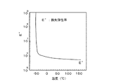
このダンパ部材13の材質としては、例えばシリコンゲル等の粘性部材が使用される。図4はシリコンゲルの硬さの温度依存性を示し、広い温度領域と周波数帯域でゲルの柔らかさが保たれている。しかし、実施例の防振アクチュエータのような極めて敏感な微小駆動をする場合において、ダンパ部材13として用いる際に、その特性変化は無視できない。例えば、温度が低くなるとシリコンゲルの損失弾性率が高くなりエネルギ損失が大きく、それに伴い位相遅れが小さくなる。逆に、常温に対して温度が高くなると、シリコンゲルの損失弾性率が低くなり、エネルギ損失は常温に対して低くなり、常温に対して位相遅れが大きくなる。
As the material of the
図5はダンパ部材13を用いない場合のばね吊り式防振アクチュエータにおいて、(a)はヨー方向、(b)はピッチ方向の周波数特性を示している。(a)、(b)の上段の縦軸はゲイン、下段の縦軸は入力電圧の位相である。上下段の図の横軸は周波数を示す。前述したように、共振周波数帯域において発振を生じ、ゲインのピークが上がり過ぎており、同時に位相遅れが生じている。
FIG. 5 shows a frequency characteristic in the yaw direction and (b) in the pitch direction in the spring-suspended vibration-proof actuator when the
それに対して、図6はシリコンゲルから成るダンパ部材13を有するばね吊り式防振アクチュエータにおいて、(a)はヨー方向、(b)はピッチ方向の周波数特性を示している。図5の場合に比べて、ダンパ部材13は共振周波数帯域での発振を緩和し、ゲインの急激な上昇を抑えているが、一方で位相が遅れ、追従性が劣化していることも分かる。
On the other hand, FIG. 6 shows the frequency characteristics in the yaw direction and (b) in the pitch direction in the spring-suspended vibration-proof actuator having the
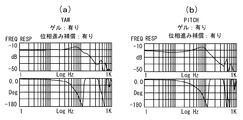
そこで、この追従遅れを防振駆動回路内で位相進み補償の演算を電気的に行うことにより、追従性の劣化を防止することが可能である。図7はダンパ部材13を有し、位相進み補償をしていないばね吊り式防振アクチュエータにおいて、(a)はヨー方向、(b)はピッチ方向の周波数特性を示している。
Therefore, it is possible to prevent the follow-up deterioration by electrically calculating the phase lead compensation in the anti-vibration driving circuit. 7A and 7B show a frequency characteristic in the yaw direction and FIG. 7B in the pitch direction in the spring-suspended vibration-proof actuator having the
図8はダンパ部材13を有し、位相進み補償を施したばね吊り式防振アクチュエータの(a)はヨー方向、(b)はピッチ方向の周波数特性である。前述したように図7に対して、図8に示すように位相進み補償を施すことによって、位相遅れが改善され追従性が向上している。
8A and 8B show the frequency characteristics in the yaw direction and FIG. 8B in the pitch direction of the spring suspension type anti-vibration actuator having the
そのため、前述した図8で示したように、ダンパ部材13を使用しない場合に対して、使用した場合は駆動制御信号の位相を進ませることで、追従遅れを補正できる。しかし、ダンパ部材13の特性に温度依存性があると、ダンパ部材13の粘性抵抗力が温度により変化し、駆動特性が変化し劣化することになる。
Therefore, as shown in FIG. 8 described above, the follow-up delay can be corrected by advancing the phase of the drive control signal when the
図9は上述の防振アクチュエータを具備したカメラシステムである光学装置の構成図を示している。交換レンズ20とカメラ本体40は、マウント60により機械的に結合され、マウント60の接点61は、交換レンズ20とカメラ本体40の間の電気的な通信を可能としている。
FIG. 9 shows a configuration diagram of an optical apparatus which is a camera system provided with the above-described vibration-proof actuator. The
交換レンズ20は複数の光学レンズにより構成される撮影光学系21を有している。撮影光学系21の光軸O上には、光軸方向に移動して焦点調節を行うフォーカスレンズ21a、光軸直交方向に移動して光学防振を行うためのシフトレンズ21b、光軸方向に移動して変倍を行う変倍レンズ21c、絞り21dが配列されている。
The
更に、撮影光学系21の振動を検出する振れ検出器22が設けられ、振れ検出器22の出力、及び防振操作スイッチ23の出力がCPU等を含む交換レンズ制御回路24に接続されている。交換レンズ制御回路24の出力は、フォーカスレンズ駆動回路25、防振駆動回路26、絞り駆動回路27に接続されている。各駆動回路25、26、27の出力は、それぞれフォーカスレンズ21aを駆動するAFアクチュエータ28、図1に示した防振アクチュエータ29、絞り21dを駆動する絞りアクチュエータ30に接続されている。防振アクチュエータ29はシフトレンズ21bを光軸Oと直交する方向に駆動する。
Further, a
撮影光学系21の後方に位置するカメラ本体40には、クイックリターンミラー41、サブミラー42、シャッタ43、撮像素子44が、撮影光学系21の光軸Oの延長上に配列されている。また、クイックリターンミラー41の反射方向には、プリズム45、ファインダ光学系46が配列されている。
A
撮像素子44の出力は駆動回路47を介してカメラ制御回路48に接続されている。サブミラー42の反射方向には焦点検出器49が配置され、その出力はカメラ制御回路48に接続され、レリーズスイッチ50、絞り操作部材51、温度計測部材52の出力もカメラ制御回路48に接続されている。更に、カメラ制御回路48の出力は、シャッタ駆動回路53を介してシャッタ43に接続されている。
The output of the
自動焦点調節(AF)を行う際には、AFアクチュエータ28の駆動力によってフォーカスレンズ21aを光軸Oの方向における合焦位置に移動させる。具体的には、カメラ本体40のカメラ制御回路48からの制御信号が接点61を介して、交換レンズ制御回路24に伝達されると、交換レンズ制御回路24から制御信号に応じた駆動信号がフォーカスレンズ駆動回路25に送られる。フォーカスレンズ駆動回路25は駆動信号に基づいてAFアクチュエータ28を駆動する。
When performing automatic focus adjustment (AF), the
光学防振を行うには、先ず光学防振機能を有効にするための防振操作スイッチ23からの操作信号が、交換レンズ制御回路24に入力される。振れ検出器22は撮影光学系21の振れに応じた検出信号を交換レンズ制御回路24に送る。交換レンズ制御回路24は防振駆動回路26に駆動制御信号を送り、防振アクチュエータ29が、シフトレンズ21bを光軸直交方向に駆動し光学防振動作を行う。
In order to perform optical image stabilization, first, an operation signal from the image
光量制限動作を行うには、複数の絞り羽根を有する絞り21dを駆動する。カメラ本体40からの制御信号が接点61を介して交換レンズ制御回路24に伝達されると、交換レンズ制御回路24が絞り駆動回路27に駆動信号を送る。絞り駆動回路27は絞りアクチュエータ30を作動させて絞り羽根を駆動し、光通過口となる開口面積つまり絞り口径を変化させる。
In order to perform the light quantity limiting operation, the
カメラ本体40のシャッタ43は複数のシャッタ羽根を有し、カメラ制御回路48はシャッタ駆動回路53に制御信号を送る。シャッタ駆動回路53は制御信号に応じた駆動信号をシャッタ43に送り、これによりシャッタ羽根は光通過口となる開口部を開閉し、撮像素子44に入射する光量つまり露光量が制御される。
The
レリーズスイッチ50が半押し操作(SW1オン)されたことが、カメラ制御回路48に伝達されると、カメラ制御回路48の制御信号によりAF動作や測光動作等の撮影準備動作が開始される。また、レリーズスイッチ50が全押し操作(SW2オン)されたことがカメラ制御回路48に伝達されると、カメラ制御回路48からの制御信号により撮像動作が開始される。
When the fact that the
絞り操作部材51が操作されたことが、カメラ制御回路48に伝達されると、カメラ制御回路48は交換レンズ制御回路24に制御信号を送り、交換レンズ制御回路24は絞り21dを駆動し、これにより光量制限動作が行われる。
When the operation of the
クイックリターンミラー41は光軸Oを含む撮影光路内に配置され、撮影光学系21からの光束をプリズム45を介してファインダ光学系46に導く観察位置と、撮影光路外に退避する撮影位置とに移動可能とされている。クイックリターンミラー41の一部はハーフミラーとなっており、このハーフミラー部分を透過した光束は、サブミラー42によって焦点検出器49に導かれる。焦点検出器49は位相差検出方式によって、撮影光学系21の焦点状態に応じた信号を生成し出力する。
The
カメラ制御回路48は焦点検出器49からの信号に基づいて、合焦を得るために必要なフォーカスレンズ21aの駆動量と駆動方向を算出し、算出情報を含む制御信号を交換レンズ制御回路24に送る。この制御信号を受けた交換レンズ制御回路24は、フォーカスレンズ駆動回路25に制御信号を送り、フォーカスレンズ21aが駆動されAF動作が行われる。
Based on the signal from the
撮像素子44はCMOSセンサやCCDセンサなどの固体撮像素子から成り、駆動回路47はカメラ制御回路48から電荷蓄積時間等を示す制御信号を受け、撮像素子44を駆動する。
The
この撮像システムでは、温度変化に応じて駆動制御信号の位相を可変とし、防振アクチュエータ29のダンパ部材13による駆動特性の劣化を補償している。そのために、交換レンズ制御回路24は温度計測部材52で得られた温度に応じた変更位相進み量のデータテーブルを持っている。
In this imaging system, the phase of the drive control signal is made variable according to the temperature change, and the deterioration of the drive characteristics due to the
このデータテーブルは表1に示すように、温度t(℃)に応じた位相進み量を表すフラグを有する。また、フラグに限らず演算係数等であってもよいことは勿論である。 As shown in Table 1, this data table has a flag indicating a phase advance amount corresponding to the temperature t (° C.). Of course, it is not limited to the flag but may be an arithmetic coefficient or the like.
表1
温度t(℃) フラグ
−30〜−21 1
−20〜−11 2
−10〜 −1 3
0〜 +9 4
+10〜+19 5
+20〜+29 6
+30〜+39 7
+40〜+49 8
+50〜+59 9
+60〜+69 10
+70〜+79 11
Table 1
Temperature t (° C.) Flag −30 to −21 1
-20 to -11 2
-10 to -1 3
0 to +9 4
+10 to +19 5
+20 to +29 6
+30 to +39 7
+40 to +49 8
+50 to +59 9
+60 to +69 10
+70 to +79 11
そして、カメラ制御回路48から通信された温度情報を基に、交換レンズ制御回路24がデータテーブルから位相進み量を選択する。その後に、防振駆動回路26に位相進み量を基にした駆動信号を送り、防振駆動回路26から防振アクチュエータ29に信号が送られ、振れ補正動作が行われる。
Then, based on the temperature information communicated from the
常温の場合の例えばフラグの6に対して、温度が低くなる場合には、位相遅れが小さくなるので、フラグの6から5〜1の何れかに変更し、位相進み補償量を小さくしてゆくことになる。また、常温に対して温度が高くなる場合は位相遅れが大きくなるので、フラグを6から7〜11の何れかに変更し、位相進み補償量を大きくする。
For example, when the temperature is lower than the
図10は主として交換レンズ制御回路24で行われる処理の内容を示したフローチャート図である。この処理は、このフローチャート図により示されるコンピュータプログラムにより、コンピュータとして機能する交換レンズ制御回路24により実行される。
FIG. 10 is a flowchart showing the contents of the processing mainly performed by the interchangeable
ステップS101では防振操作スイッチ23がオンかオフかを交換レンズ制御回路24が判別し、オンである場合はステップS102に進み、オフの場合はステップS111に進む。
In step S101, the interchangeable
ステップS102では、レリーズスイッチ50の半押し(SW1)がなされたかどうかを交換レンズ制御回路24が判別し、オンである場合はステップS103に進み、オフの場合はステップS102を繰り返す。ステップS103では、交換レンズ制御回路24がカメラ制御回路48を介して温度計測部材52からの温度情報を取得する。ステップS104では、交換レンズ制御回路24は温度に応じて変更位相進み量テーブルを参照する。ステップS105では、交換レンズ制御回路24が取得した温度情報を基にして、変更位相進み量のデータテーブルから適当な位相進み量又はそれに相当するフラグ等を選択する。
In step S102, the interchangeable
ステップS106では振れ検出信号が交換レンズ制御回路24に送られ、ステップS107では振れ検出信号及び変更位相進み量情報を基にして、交換レンズ制御回路24が振れ補正演算を実行する。ステップS108では、ステップS107で演算された情報を基にして振れ補正が開始される。ステップS109では、レリーズスイッチ50の全押し(SW2)がなされたかどうかを交換レンズ制御回路24が判別し、オンである場合はステップS110に進み、オフの場合はステップS109を繰り返す。
In step S106, the shake detection signal is sent to the interchangeable
ステップS111では、レリーズスイッチ50の半押し(SW1)がなされたかどうかを交換レンズ制御回路24が判別し、半押し(SW1)の場合はステップS112に進んで通常撮影動作を行い、オフの場合はステップS111の判断を繰り返す。
In step S111, the interchangeable
なお、上述した実施例では、温度計測部材52をカメラ本体40に設けた例について説明したが、温度計測部材52を交換レンズ20内に設ける構成としてもよい。
In the above-described embodiment, the example in which the
本発明の好ましい実施例について説明したが、本発明はこれらの実施例に限定されないことは云うまでもなく、その要旨の範囲内で種々の変形及び変更が可能である。また、本発明の光学装置は、交換レンズであるレンズ装置、また交換レンズを着脱自在に装着したカメラを含むカメラシステム、更に撮影光学系が一体に構成されたカメラを含んでいる。 Although the preferred embodiments of the present invention have been described, it goes without saying that the present invention is not limited to these embodiments, and various modifications and changes can be made within the scope of the gist thereof. The optical device of the present invention includes a lens device that is an interchangeable lens, a camera system that includes a camera in which the interchangeable lens is detachably mounted, and a camera in which a photographing optical system is integrated.
1 シフトベース
1a 保持部
2 シフト鏡筒
3 防振光学系
6 位置規制ピン
12 位置検出部材
13 ダンパ部材
20 交換レンズ
21 撮影光学系
22 振れ検出器
23 防振操作スイッチ
24 交換レンズ制御回路
26 防振駆動回路
27 絞り駆動回路
28 AFアクチュエータ
29 防振アクチュエータ
30 絞りアクチュエータ
40 カメラ本体
44 撮像素子
48 カメラ制御回路
49 焦点検出器
50 レリーズスイッチ
51 絞り操作部材
52 温度計測部材
60 マウント
DESCRIPTION OF
Claims (7)
防振光学系を保持する保持部材と、
前記保持部材を光軸直交平面内で移動させる駆動部と、
前記保持部材を前記平面内で変位可能に弾性的に支持する弾性部材と、
前記振動検出部の出力に基づいて前記駆動部に制御信号を送り前記駆動部の制御を行う制御部と、
温度を測定する温度測定部と、
前記保持部材の移動方向の制動を行う粘性部材と、を有し、
前記制御部は、前記温度測定部により得られた温度に基づいて前記駆動部に送る制御信号の位相進み量を変更することを特徴とする光学装置。 A vibration detection unit for detecting vibration;
A holding member for holding the vibration isolating optical system;
A drive unit that moves the holding member in a plane orthogonal to the optical axis;
An elastic member that elastically supports the holding member so as to be displaceable in the plane;
A control unit that controls the drive unit by sending a control signal to the drive unit based on the output of the vibration detection unit;
A temperature measuring unit for measuring the temperature;
A viscous member that performs braking in the moving direction of the holding member,
Wherein, the optical apparatus characterized by changing the amount of phase lead of the control signal sent to the drive unit based on the obtained temperature by the temperature measuring unit.
前記制御部は、前記位置検出部の出力に基づいて前記保持部材の位置を制御することを特徴とする請求項1乃至5のいずれか1項に記載の光学装置。 A position detection unit for detecting the position of the holding member;
The optical device according to claim 1, wherein the control unit controls the position of the holding member based on an output of the position detection unit.
振れを検出する振動検出部と、
防振光学系を保持する保持部材と、
前記保持部材を光軸直交平面内で移動させる駆動部と、
前記保持部材を前記平面内で変位可能に弾性的に支持する弾性部材と、
前記振動検出部の出力に基づいて前記駆動部に制御信号を送り前記駆動部の制御を行う制御部と、
前記保持部材の移動方向の制動を行う粘性部材と、を有し、
前記制御部は、前記カメラ本体に設けられた温度測定部により得られた温度に基づいて前記駆動部に送る制御信号の位相進み量を変更することを特徴とする光学装置。 An optical device that can be attached to a camera body,
A vibration detection unit for detecting vibration;
A holding member for holding the anti-vibration optical system;
A drive unit that moves the holding member in a plane orthogonal to the optical axis;
An elastic member that elastically supports the holding member so as to be displaceable in the plane;
A control unit that controls the drive unit by sending a control signal to the drive unit based on the output of the vibration detection unit;
A viscous member that performs braking in the moving direction of the holding member,
Wherein, the optical apparatus characterized by changing the amount of phase lead of the control signal sent to the drive unit based on the obtained temperature by the temperature measuring unit provided on the camera body.
Priority Applications (4)
| Application Number | Priority Date | Filing Date | Title |
|---|---|---|---|
| JP2006326822A JP4956161B2 (en) | 2006-12-04 | 2006-12-04 | Optical device |
| US11/938,502 US7830414B2 (en) | 2006-12-04 | 2007-11-12 | Optical apparatus with stabilization control based on temperature |
| CNB2007101865051A CN100565317C (en) | 2006-12-04 | 2007-12-04 | Optical device |
| EP07122309.3A EP1933198B1 (en) | 2006-12-04 | 2007-12-04 | Optical apparatus |
Applications Claiming Priority (1)
| Application Number | Priority Date | Filing Date | Title |
|---|---|---|---|
| JP2006326822A JP4956161B2 (en) | 2006-12-04 | 2006-12-04 | Optical device |
Publications (3)
| Publication Number | Publication Date |
|---|---|
| JP2008139639A JP2008139639A (en) | 2008-06-19 |
| JP2008139639A5 JP2008139639A5 (en) | 2010-01-28 |
| JP4956161B2 true JP4956161B2 (en) | 2012-06-20 |
Family
ID=39356613
Family Applications (1)
| Application Number | Title | Priority Date | Filing Date |
|---|---|---|---|
| JP2006326822A Active JP4956161B2 (en) | 2006-12-04 | 2006-12-04 | Optical device |
Country Status (4)
| Country | Link |
|---|---|
| US (1) | US7830414B2 (en) |
| EP (1) | EP1933198B1 (en) |
| JP (1) | JP4956161B2 (en) |
| CN (1) | CN100565317C (en) |
Families Citing this family (14)
| Publication number | Priority date | Publication date | Assignee | Title |
|---|---|---|---|---|
| JP5517431B2 (en) * | 2008-09-29 | 2014-06-11 | キヤノン株式会社 | Optical apparatus and imaging apparatus |
| JP2010096859A (en) * | 2008-10-14 | 2010-04-30 | Nidec Sankyo Corp | Optical unit with shake correcting function |
| JP5451260B2 (en) * | 2009-08-28 | 2014-03-26 | キヤノン株式会社 | Control device, control system, command transmission method, and program |
| JP5404256B2 (en) * | 2009-08-31 | 2014-01-29 | キヤノン株式会社 | Vibration correction apparatus and imaging apparatus |
| JP5693163B2 (en) * | 2010-11-11 | 2015-04-01 | キヤノン株式会社 | Vibration correction device, lens barrel, and optical apparatus |
| JP2012203082A (en) * | 2011-03-24 | 2012-10-22 | Hoya Corp | Lens barrel having vibration-free insertion/removal optical element |
| KR101300341B1 (en) * | 2011-12-05 | 2013-08-28 | 삼성전기주식회사 | Camera module |
| JP6170395B2 (en) * | 2013-09-26 | 2017-07-26 | キヤノン株式会社 | Imaging apparatus and control method thereof |
| JP6648984B2 (en) * | 2014-12-26 | 2020-02-19 | 日本電産サンキョー株式会社 | Actuator |
| US10317649B2 (en) | 2016-08-25 | 2019-06-11 | Apple Inc. | Camera actuator vibration damping |
| US10715730B1 (en) | 2017-03-29 | 2020-07-14 | Apple Inc. | Damper arrangement for actuator damping |
| US11350018B2 (en) | 2019-08-06 | 2022-05-31 | Apple Inc. | Camera with bumper for cushioning lateral movement |
| TWI704385B (en) * | 2020-05-20 | 2020-09-11 | 大陽科技股份有限公司 | Lens driving module and electronic device |
| CN217404602U (en) * | 2022-05-30 | 2022-09-09 | 新思考电机有限公司 | Base for lens driving, anti-shake driving mechanism, device and camera equipment |
Family Cites Families (16)
| Publication number | Priority date | Publication date | Assignee | Title |
|---|---|---|---|---|
| JPH0281009A (en) * | 1988-09-19 | 1990-03-22 | Canon Inc | Supporting structure for optical element holding frame |
| JP3141039B2 (en) * | 1991-11-29 | 2001-03-05 | キヤノン株式会社 | Anti-vibration device |
| JP3364945B2 (en) * | 1992-01-31 | 2003-01-08 | ソニー株式会社 | Camera shake correction device and camera shake correction method |
| JPH07294997A (en) * | 1994-04-28 | 1995-11-10 | Canon Inc | Camera-shake correcting device |
| JP2941647B2 (en) * | 1994-05-10 | 1999-08-25 | 富士写真光機株式会社 | Image stabilization optics |
| US5861915A (en) * | 1995-05-31 | 1999-01-19 | Sony Corporation | Temperature-dependant, frequency-compensated hand deviation correction device for video camera |
| US6064827A (en) * | 1997-05-16 | 2000-05-16 | Canon Kabushiki Kaisha | Image stabilizer |
| JPH10319465A (en) | 1997-05-16 | 1998-12-04 | Canon Inc | Lens shifting device |
| JPH116951A (en) * | 1997-06-16 | 1999-01-12 | Canon Inc | Lens device or optical equipment |
| US5978600A (en) * | 1997-09-30 | 1999-11-02 | Nikon Corporation | Motion compensation device to compensate for motion of an optical system without using motion sensors |
| JP2001264836A (en) * | 2000-03-21 | 2001-09-26 | Canon Inc | Image blurring corrector |
| JP4669118B2 (en) * | 2000-10-31 | 2011-04-13 | キヤノン株式会社 | Vibration correction apparatus and optical apparatus |
| JP2005338298A (en) * | 2004-05-25 | 2005-12-08 | Sumida Corporation | Blur correcting optical device |
| US20060018643A1 (en) * | 2004-07-21 | 2006-01-26 | Stavely Donald J | Magnet configuration for image stabilization |
| US7679647B2 (en) * | 2004-07-21 | 2010-03-16 | Hewlett-Packard Development Company, L.P. | Flexible suspension for image stabilization |
| JP2006300997A (en) * | 2005-04-15 | 2006-11-02 | Tamron Co Ltd | Imaging apparatus with image blur preventing function |
-
2006
- 2006-12-04 JP JP2006326822A patent/JP4956161B2/en active Active
-
2007
- 2007-11-12 US US11/938,502 patent/US7830414B2/en active Active
- 2007-12-04 CN CNB2007101865051A patent/CN100565317C/en active Active
- 2007-12-04 EP EP07122309.3A patent/EP1933198B1/en active Active
Also Published As
| Publication number | Publication date |
|---|---|
| US20080129830A1 (en) | 2008-06-05 |
| CN100565317C (en) | 2009-12-02 |
| CN101196669A (en) | 2008-06-11 |
| EP1933198A2 (en) | 2008-06-18 |
| JP2008139639A (en) | 2008-06-19 |
| EP1933198A3 (en) | 2011-01-05 |
| EP1933198B1 (en) | 2015-02-25 |
| US7830414B2 (en) | 2010-11-09 |
Similar Documents
| Publication | Publication Date | Title |
|---|---|---|
| JP4956161B2 (en) | Optical device | |
| US7154682B2 (en) | Optical apparatus | |
| US7460775B2 (en) | Optical apparatus including efficiently arranged shake correction means | |
| RU2399942C2 (en) | Lens device and photographic camera | |
| JP5053985B2 (en) | DRIVE DEVICE AND IMAGING DEVICE USING THE DRIVE DEVICE | |
| JP2007163595A (en) | Optical equipment | |
| US11800241B2 (en) | Interchangeable lens capable of transmitting diaphragm driving information to shooting apparatus, shooting apparatus, and camera system | |
| JP2007163593A (en) | Optical equipment and imaging system | |
| JP2018116318A (en) | Lens barrel | |
| JP5398140B2 (en) | Imaging apparatus and control method thereof | |
| JP2007163596A (en) | Optical equipment | |
| JP2008139640A (en) | Imaging apparatus | |
| JP2007271996A (en) | Lens device and camera system | |
| JP2010091947A (en) | Shake correcting device and optical equipment | |
| JP4701006B2 (en) | Camera shake detection device and photographing device | |
| JP2006330077A (en) | Optical equipment | |
| JP2016008995A (en) | Lens barrel and imaging device | |
| JP2009217202A (en) | Optical apparatus and optical equipment | |
| JP2007011021A (en) | Electronic camera and camera system | |
| JP5441950B2 (en) | Optical apparatus and imaging system | |
| JP5061982B2 (en) | Optical device and camera | |
| JP2019184702A (en) | Mirror drive device, and imaging device | |
| JP2012215643A (en) | Interchangeable lens and camera body | |
| JP2010276813A (en) | Imaging apparatus | |
| JP2013195694A (en) | Lens unit and camera body |
Legal Events
| Date | Code | Title | Description |
|---|---|---|---|
| A521 | Written amendment |
Free format text: JAPANESE INTERMEDIATE CODE: A523 Effective date: 20091203 |
|
| A621 | Written request for application examination |
Free format text: JAPANESE INTERMEDIATE CODE: A621 Effective date: 20091203 |
|
| RD01 | Notification of change of attorney |
Free format text: JAPANESE INTERMEDIATE CODE: A7421 Effective date: 20100218 |
|
| RD01 | Notification of change of attorney |
Free format text: JAPANESE INTERMEDIATE CODE: A7421 Effective date: 20100630 |
|
| A977 | Report on retrieval |
Free format text: JAPANESE INTERMEDIATE CODE: A971007 Effective date: 20110628 |
|
| A131 | Notification of reasons for refusal |
Free format text: JAPANESE INTERMEDIATE CODE: A131 Effective date: 20110705 |
|
| A521 | Written amendment |
Free format text: JAPANESE INTERMEDIATE CODE: A523 Effective date: 20110901 |
|
| A131 | Notification of reasons for refusal |
Free format text: JAPANESE INTERMEDIATE CODE: A131 Effective date: 20111129 |
|
| A521 | Written amendment |
Free format text: JAPANESE INTERMEDIATE CODE: A523 Effective date: 20120123 |
|
| TRDD | Decision of grant or rejection written | ||
| A01 | Written decision to grant a patent or to grant a registration (utility model) |
Free format text: JAPANESE INTERMEDIATE CODE: A01 Effective date: 20120313 |
|
| A01 | Written decision to grant a patent or to grant a registration (utility model) |
Free format text: JAPANESE INTERMEDIATE CODE: A01 |
|
| A61 | First payment of annual fees (during grant procedure) |
Free format text: JAPANESE INTERMEDIATE CODE: A61 Effective date: 20120316 |
|
| R151 | Written notification of patent or utility model registration |
Ref document number: 4956161 Country of ref document: JP Free format text: JAPANESE INTERMEDIATE CODE: R151 |
|
| FPAY | Renewal fee payment (event date is renewal date of database) |
Free format text: PAYMENT UNTIL: 20150323 Year of fee payment: 3 |