JP4952015B2 - Temperature monitoring method for electronic equipment unit - Google Patents
Temperature monitoring method for electronic equipment unit Download PDFInfo
- Publication number
- JP4952015B2 JP4952015B2 JP2006086899A JP2006086899A JP4952015B2 JP 4952015 B2 JP4952015 B2 JP 4952015B2 JP 2006086899 A JP2006086899 A JP 2006086899A JP 2006086899 A JP2006086899 A JP 2006086899A JP 4952015 B2 JP4952015 B2 JP 4952015B2
- Authority
- JP
- Japan
- Prior art keywords
- temperature
- printed board
- temperature sensor
- electronic device
- mounting
- Prior art date
- Legal status (The legal status is an assumption and is not a legal conclusion. Google has not performed a legal analysis and makes no representation as to the accuracy of the status listed.)
- Expired - Fee Related
Links
- 238000012544 monitoring process Methods 0.000 title claims description 17
- 238000000034 method Methods 0.000 title claims description 10
- 239000012080 ambient air Substances 0.000 description 10
- 230000005856 abnormality Effects 0.000 description 8
- 230000000694 effects Effects 0.000 description 4
- 239000003570 air Substances 0.000 description 3
- 238000001816 cooling Methods 0.000 description 2
- 238000005259 measurement Methods 0.000 description 2
- 230000002159 abnormal effect Effects 0.000 description 1
- 238000010586 diagram Methods 0.000 description 1
- 238000010438 heat treatment Methods 0.000 description 1
- 238000009423 ventilation Methods 0.000 description 1
Images


Classifications
-
- H—ELECTRICITY
- H01—ELECTRIC ELEMENTS
- H01L—SEMICONDUCTOR DEVICES NOT COVERED BY CLASS H10
- H01L2924/00—Indexing scheme for arrangements or methods for connecting or disconnecting semiconductor or solid-state bodies as covered by H01L24/00
- H01L2924/0001—Technical content checked by a classifier
- H01L2924/0002—Not covered by any one of groups H01L24/00, H01L24/00 and H01L2224/00
Description
この発明は、電子機器ユニットの温度監視方法に関するものである。 The present invention relates to temperature monitoring method for an electronic device unit.
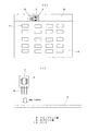
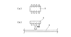
電子機器ユニットにおいては、その温度監視、温度制御のために、その内部に実装されたプリント板に温度センサを実装することがある。図7は従来の電子機器ユニットの温度測定装置の一例を示し、1はユニット内部に固定された温度センサであり、温度センサ1には配線2を介してコネクタ3が接続され、コネクタ3はプリント板4に設けられた接続端子4aに接続される。この例では、温度センサ1は配線2を介してプリント板4と接続されているので、温度センサ1にプリント板4の熱が熱伝導により伝わることはなく、温度センサ1は周囲の空気温度を正確に測定することができる。図8(a),(b)はデバイス型温度センサ5の平面図及びこの温度センサ5をプリント板4に実装する状態を示し、デバイス型の温度センサにはDIP形状にものの他に表面実装タイプがあるが、いずれの場合もプリント板4に直接実装される。温度センサ5はプリント板4に直接実装されるため、プリント板4の温度が熱伝導により温度センサ5に伝わり、温度センサ5の測定温度はプリント板4の温度とその周囲の空気温度により決まる温度となる。特に、SMD部品を自然空冷のユニットのプリント板4に実装した場合、SMD部品の温度はプリント板4の温度とほぼ等しくなるため、プリント板4の温度の測定が容易となる。
In an electronic device unit, a temperature sensor may be mounted on a printed board mounted therein for temperature monitoring and temperature control. FIG. 7 shows an example of a temperature measuring apparatus for a conventional electronic device unit. Reference numeral 1 denotes a temperature sensor fixed inside the unit. A
一方、自然空冷電子機器ユニットの温度監視においては、温度センサの取付位置及び監視対象は次のように行われている。まず、局部発熱する部品やシステム上最も重要なデバイス(例えば、CPUプロセッサ)等の特定部品に温度センサを取り付けた場合、監視対象は特定部品温度となり、この場合、ユニット全体の監視はできないが、対象部品の監視は精度良く行われる。次に、温度センサをユニット吸気部に取り付けた場合、ユニット吸気(周囲)温度が監視対象となり、測定結果はユニットの温度仕様に基づいた判定値で評価される。即ち、ユニットが最大負荷となった時の各部品温度が許容内に必ず入るように判定されるために、安全な監視が可能となる。反面、負荷が少なく、内部温度が低いにもかかわらず、吸気(周囲)温度が高いだけで、許容外と判定されることがある。次に、温度センサをユニット排気部に取り付けた場合、ユニット排気(内部)温度が監視対象となり、ユニット負荷に吸気(周囲)温度をプラスした温度で判定を行うこととなり、負荷を抑えてより高い周囲温度の環境で使用することが可能となる。即ち、図9はユニット負荷とユニット許容周囲温度との関係を示し、イの部分は吸気尾温度のみで判定した場合の許容範囲であり、ロの部分はユニット負荷に対応した許容範囲であり、負荷が小さいほどユニット許容周囲温度は高くなる。ただし、ユニット排気温度を監視対象とした場合、局部発熱部品の監視はできない。 On the other hand, in the temperature monitoring of the natural air-cooled electronic device unit, the mounting position of the temperature sensor and the monitoring target are performed as follows. First, when a temperature sensor is attached to a specific part such as a part that generates heat locally or the most important device in the system (for example, a CPU processor), the monitoring target is a specific part temperature. In this case, the entire unit cannot be monitored. The target parts are monitored with high accuracy. Next, when the temperature sensor is attached to the unit intake section, the unit intake (ambient) temperature becomes a monitoring target, and the measurement result is evaluated by a determination value based on the temperature specification of the unit. That is, since it is determined that the temperature of each component when the unit reaches the maximum load is always within the allowable range, safe monitoring is possible. On the other hand, even though the load is small and the internal temperature is low, it may be determined that the intake (ambient) temperature is high and that it is not acceptable. Next, when a temperature sensor is attached to the unit exhaust section, the unit exhaust (internal) temperature will be monitored, and judgment will be made at a temperature obtained by adding the intake (ambient) temperature to the unit load. It can be used in an ambient temperature environment. That is, FIG. 9 shows the relationship between the unit load and the unit allowable ambient temperature, the part a is the allowable range when judged only by the intake tail temperature, and the part b is the allowable range corresponding to the unit load. The smaller the load, the higher the allowable ambient temperature of the unit. However, when the unit exhaust temperature is monitored, local heating parts cannot be monitored.
この出願の発明に関連する技術文献情報としては、次のものがある。
図7に示した従来の電子機器ユニットの温度測定装置においては、プリント板4に温度センサ1をコネクタ3により接続しているため、組立工数が多くなり、高価になる。また、温度センサ1の取付構造が大きくなり、狭い場所では取付ができず、取付が可能な場合でも熱の対流を阻害することとなった。又、周囲の空気温度を測定するのには適しているが、プリント板4の表面温度を測定するためには、温度センサ1の取付構造を工夫する必要があり、精度良く測定することは困難であった。一方、図8に示すように、デバイス型の温度センサ5を用いた場合には、他の部品と同様に機械実装が可能であり、部品単価が安くなるために、安価になるが、温度センサ5がプリント板4上にあるために、周囲の空気温度が測定できなかった。特に、近傍に高発熱部品が実装されている場合には、その部品からの熱伝導による熱の影響を大きく受けるため、周囲の空気温度の測定は不可能であった。
In the conventional temperature measuring device for an electronic device unit shown in FIG. 7, the temperature sensor 1 is connected to the printed
又、上記した従来の電子機器ユニットの温度監視方法においては、自然空冷の電子機器ユニットの実装可能方向が多方向の場合、方向により温度センサによる測定温度が変化し、特定部品の温度測定により温度監視、制御を行うことしかできず、ユニット内の部品全体の温度監視、制御を行うことは不可能であった。 Further, in the above-described conventional temperature monitoring method for an electronic device unit, when the mounting direction of a naturally air-cooled electronic device unit is multi-directional, the temperature measured by the temperature sensor varies depending on the direction, and the temperature is measured by measuring the temperature of a specific component. It was only possible to monitor and control, and it was impossible to monitor and control the temperature of the entire components in the unit.
この発明は上記のような課題を解決するために成されたものであり、周囲の空気温度を安価、正確に測定することができるとともに、実装方向が多方向である自然空冷ユニットの温度監視、制御が可能な電子機器ユニットの温度監視方法を得ることを目的とする。 The present invention has been made to solve the above-described problems, and can monitor the temperature of a natural air cooling unit in which the ambient air temperature can be measured inexpensively and accurately and the mounting direction is multidirectional. and to obtain a temperature monitoring method for an electronic device unit capable controlled.
請求項1に係る電子機器ユニットの温度監視方法は、電子機器ユニット内に実装されたプリント板の一方の側及び他方の側にそれぞれ温度センサを設け、一方の側と他方の側との温度差が正、負、ほぼ零により、一方の側が上側の排気側の縦実装か他方の側が上側の排気側の縦実装か水平実装かを判定するとともに、各実装方向の場合の排気側温度が各実装方向別に設定された最大許容排気温度より低く、かつ縦実装の場合に上記温度差の絶対値が最大許容温度上昇値より小さいことにより、電子機器ユニット内が温度上許容範囲内であると判定するものである。 The temperature monitoring method for an electronic device unit according to claim 1 is provided with temperature sensors on one side and the other side of a printed board mounted in the electronic device unit, respectively, and a temperature difference between one side and the other side. Is positive, negative, or nearly zero, and it is determined whether one side is the vertical mounting on the upper exhaust side or the other side is the vertical mounting or horizontal mounting on the upper exhaust side, and the exhaust side temperature in each mounting direction is It is determined that the electronic device unit is within the allowable temperature range because the absolute value of the temperature difference is lower than the maximum allowable temperature rise value when the vertical mounting is lower than the maximum allowable exhaust temperature set for each mounting direction. To do.
請求項1によれば、電子機器ユニット内に実装されたプリント板の一方の側及び他方の側にそれぞれ温度センサを設け、各温度センサの測定温度の差が正、負、ほぼ零かによりプリント板の実装方向を判定し、各実装方向の場合の排気側温度が実装方向別に設定された最大許容排気温度より低いことにより、電子機器ユニット内の温度が許容温度内であることを判定し、さらに縦実装の場合に各温度センサの測定温度差の絶対値が最大許容温度上昇値より小さいことにより、内部実装異常や動作異常が判定される。従って、実装可能方向が多方向の場合に、実装方向を判定して、実装方向別に排気側温度が最大許容排気温度より低いこと、及び縦実装の場合に測定温度差の絶対値が最大許容温度上昇値より小さいことにより、電子機器ユニット内が温度上許容範囲内であると判定することができる。 According to the first aspect of the present invention , the temperature sensor is provided on one side and the other side of the printed board mounted in the electronic device unit, and printing is performed depending on whether the difference in measured temperature of each temperature sensor is positive, negative, or substantially zero. Determine the mounting direction of the board, determine that the temperature in the electronic device unit is within the allowable temperature by the exhaust side temperature in each mounting direction being lower than the maximum allowable exhaust temperature set for each mounting direction, Further, in the case of vertical mounting, the internal mounting abnormality or operation abnormality is determined by the absolute value of the measured temperature difference of each temperature sensor being smaller than the maximum allowable temperature rise value. Therefore, when the mountable directions are multi-directional, the mounting direction is determined, the exhaust side temperature is lower than the maximum allowable exhaust temperature for each mounting direction, and the absolute value of the measured temperature difference is the maximum allowable temperature for vertical mounting. By being smaller than the increase value, it can be determined that the inside of the electronic device unit is within the allowable range in terms of temperature.
参考例1
図1(a),(b)はこの発明の参考例1の電子機器ユニットの温度測定装置の平面図及びその要部拡大図を示し、プリント板4には実装部品6を実装するとともに、デバイス型温度センサ5を実装する。プリント板4には実装部品6や温度センサ5間を接続する配線パターンが形成されており、これにより回路が形成される。プリント板4の温度センサ5を実装した部分の周囲には、温度センサ5とプリント板4に形成された回路とを接続する配線パターンが通過するエリア4bを残して切り欠き溝4cを形成する。
Reference example 1
FIGS. 1A and 1B are a plan view and an enlarged view of a main part of a temperature measuring device for an electronic device unit according to a first embodiment of the present invention. A
参考例1においては、プリント板4の温度センサ5を実装した部分の周囲に、温度センサ5とプリント板4に形成された回路とを接続する配線パターンが通過するエリア4bを残して切り欠き溝4cを形成しており、プリント板4と温度センサ5を実装した部分との間の熱抵抗が非常に大きくなり、近傍に高発熱部品が実装されていても、その部品からの熱伝導による影響をほとんど受けなくなり、温度センサ5の周囲の空気温度を精度良く測定できるようになった。しかも、デバイス型の温度センサ5は機械実装が可能であり、安価にすることができる。従って、ユニット内の空気温度を安価に正確に測定することができる。又、温度センサ5をプリント板4に実装するだけでよく、取付構造が簡単小形で安価になる。さらに、配線が不要で通風抵抗の要因となるものがなく、安定した精度が高い測定が可能になるとともに、狭い空間でも実装可能である。また、周囲に高発熱部品が実装されていても、温度センサ5を風上側に設けることにより、高発熱部品の熱の影響を避けることができる。
In Example 1, the periphery of the portion mounting the
参考例2
図2はこの発明の参考例2による電子機器ユニットの温度測定装置の平面図であり、電子機器ユニット7内のプリント板4には実装部品6を実装するとともに、プリント板4の吸気側または排気側にプリント板4の拡張部分4d,4eを設け、拡張部分4d,4eにはデバイス型温度センサ5を実装する。又、プリント板4とその拡張部分4d,4eとの接続部分4f,4gは温度センサ5とプリント板4に形成された回路とを接続する配線パターンが通過するのみのエリアとする。
Reference example 2
FIG. 2 is a plan view of a temperature measuring device for an electronic device unit according to a second embodiment of the present invention. The
参考例2においては、プリント板4とその吸気側又は排気側の拡張部分4d,4eとの接続部分4f,4gを温度センサ5とプリント板4に形成された回路とを接続する配線パターンが通過するのみのエリアとしたので、プリント板4とその拡張部分4d,4eとの間の熱抵抗が非常に大きくなり、近傍に高発熱部品が実装されていても、その部品からの伝導による熱の影響をあまり受けなくなり、温度センサ5は周囲の空気温度を精度良く測定することができる。又、デバイス型温度センサ5は機械実装が可能で安価になり、周囲の空気温度を安価に精度よく測定することができる。また、温度センサ5を吸気側の拡張部分4dに設ければ、高発熱部品の風上側に設けることができ、温度センサ5は高発熱部品の熱の影響を受けず、周囲の空気温度を精度良く測定することができる。又、温度センサ5を排気側の拡張部分4eに設ければ、高発熱部品の風下側に設けることになるが、風の通り道に設けられるので、冷却効果が良く、やはり高発熱部品の熱の影響をほとんど受けない。その他、参考例1と同様の効果を奏する。
In the reference example 2 , the wiring pattern connecting the
参考例3
図3(a),(b)は参考例3による電子機器ユニットの温度測定装置におけるプリント板の平面図及び小プリント板をメインプリント板に実装する状態を示し、図3(a)に示すようにメインプリント板8と小プリント板9とを共取りにより一体に製作し、メインプリント板8部分には実装部品6を実装するとともに、小プリント板9部分にはデバイス型温度センサ5を実装し、小プリント板9にはリード10を設ける。ここで、メインプリント板8と小プリント板9を切り離し、捨て基板となる部分8aも切り離す。次に、図3(b)に示すようにリード10をメインプリント板8に半田付けし、小プリント板9をメインプリント板8に実装する。ここで、小プリント板9のリード10は、メインプリント板8と温度センサ5間の熱抵抗を大きくするために長く細い形状とする。
Reference example 3
FIGS. 3A and 3B show a plan view of a printed board and a state in which a small printed board is mounted on the main printed board in the temperature measuring device for an electronic device unit according to Reference Example 3 , as shown in FIG. In addition, the main printed
参考例3においては、小プリント板9を細長いリード10を介してメインプリント板8に実装したので、小プリント板9に実装された温度センサ5とメインプリント板8との間の熱抵抗が大きくなり、温度センサ5はメインプリント板8に実装された実装部品6の熱の影響をほとんど受けなくなり、安価なデバイス型温度センサ5を用いて、周囲の空気温度を正確に測定することができる。その他、参考例1と同様の効果を奏する。
In Reference Example 3 , since the small printed
実施最良形態1
図4〜図6は実施最良形態1による電子機器ユニットの温度監視方法を説明する説明図であり、図4は電子機器ユニット7内に実装されたプリント板4がその一方の側を電子機器ユニット7の上側の排気側にして縦実装された場合を示し、図5はプリント板がその他方の側を電子機器ユニット7の上側の排気側にして縦実装された場合を示し、図6はプリント板4が水平実装された場合を示す。又、図4の場合、縦実装されたプリント板4の一方の側(上側の排気側)に温度センサ11aを設けるとともに、プリント板4の他方の側(下側の吸気側)に温度センサ11bを設ける。また、図5の場合には、縦実装されたプリント板4の一方の側(下側の吸気側)に温度センサ11aを設けるとともに、プリント板4の他方の側(上側の排気側)に温度センサ11bを設ける。さらに、図6の場合には、水平実装されたプリント板4の一方の側(吸気側又は排気側)に温度センサ11aを設けるとともに、プリント板4の他方の側(排気側又は吸気側)に温度センサ11bを設ける。
Best Embodiment 1
4 to 6 are explanatory views for explaining a temperature monitoring method for the electronic device unit according to the first embodiment, and FIG. 4 shows the printed
ここで、温度センサ11a,11bの測定温度をTa,Tbとして、その温度差ΔTをΔT=Ta−Tbの式により演算し、このΔTにより実装方向を判定する。即ち、ΔTが正の場合は、図4に示すようにプリント板4の一方の側が上側の排気側の縦実装の場合と判定し、ΔTが負の場合は、図5に示すようにプリント板4の他方の側が上側の排気側の縦実装の場合と判定し、ΔTがほぼ零の場合は、図6に示すようにプリント板4が水平実装の場合と判定する。又、図4の場合、即ち、プリント板4の一方の側が上側の排気側の縦実装の場合には、その判定値である縦実装最大許容排気温度(内部部品仕様温度が満足する時の最大温度、以下同様)をTvamaxとして、排気側温度Ta<Tvamaxか否かを判定する。また、図5の場合、即ち、プリント板4の他方の側が上側の排気側の縦実装の場合には、その判定値である縦実装最大許容排気温度をTvbmaxとして、排気側温度Tb<Tvbmaxか否かを判定する。さらに、図6の場合、即ち、プリント板4が水平実装の場合には、その判定値である縦実装最大許容排気温度をThamaxとして、排気側温度Ta又はTb<Thamaxか否かを判定する。このように、それぞれの場合に排気側温度が実装方向別の最大許容排気温度より低いことにより、電子機器ユニット7内の温度が許容温度内であると判定する。
Here, the measured temperatures of the
さらに、図4,図5の縦実装の場合には、上記ΔTの絶対値が判定値である最大許容温度上昇値ΔTmaxより小さいことが必要であり、これにより内部実装異常や動作異常がないことが判定される。 Furthermore, in the case of the vertical mounting shown in FIGS. 4 and 5, the absolute value of ΔT needs to be smaller than the maximum allowable temperature rise value ΔTmax, which is a determination value, so that there is no internal mounting abnormality or abnormal operation. Is determined.
実施最良形態1においては、プリント板4の一方の側と他方の側に温度センサ11a,11bを設け、それぞれの測定温度をTa,Tbとして、その温度差ΔTが正の場合には一方の側が上側の排気側の縦実装と判定することができ、負の場合には他方の側が上側の排気側の縦実装と判定することができ、ほぼ零の場合には水平実装と判定することができる。又、排気側温度が実装方向別の最大許容排気温度より低いことにより、電子機器ユニット7内の温度が許容温度内であると判定し、かつ縦実装の場合には温度差の絶対値が最大許容温度上昇値より小さいことにより、電子機器ユニット7内に内部実装異常及び動作異常がないことが判定される。そして、これらの条件をすべて満足するときに電子機器ユニット7内が温度上許容範囲内であると判定する。
Implemented in the best mode 1, the
以上のようにして、実施可能方向が多方向の自然空冷電子機器ユニット7の温度監視、制御が可能となり、また各実装方向の排気側温度を判定温度とすることにより、電子機器ユニット7内の負荷を抑えることでより高い周囲温度の環境で使用可能となり、実装方向に応じた詳細な温度制御、監視が可能となって、信頼性が向上する。又、従来の技術にはなかった実装異常や内部部品の異常による温度異常なども検出可能となる。
As described above, it is possible to monitor and control the temperature of the natural air-cooled
4…プリント板
4b…配線パターン通過エリア
4c…切り欠き溝
4d,4e…拡張部分
4f,4g…接続部分
5…デバイス型温度センサ
6…実装部品
7…電子機器ユニット
8…メインプリント板
9…小プリント板
10…リード
DESCRIPTION OF
Claims (1)
Priority Applications (1)
| Application Number | Priority Date | Filing Date | Title |
|---|---|---|---|
| JP2006086899A JP4952015B2 (en) | 2006-03-28 | 2006-03-28 | Temperature monitoring method for electronic equipment unit |
Applications Claiming Priority (1)
| Application Number | Priority Date | Filing Date | Title |
|---|---|---|---|
| JP2006086899A JP4952015B2 (en) | 2006-03-28 | 2006-03-28 | Temperature monitoring method for electronic equipment unit |
Publications (2)
| Publication Number | Publication Date |
|---|---|
| JP2007263636A JP2007263636A (en) | 2007-10-11 |
| JP4952015B2 true JP4952015B2 (en) | 2012-06-13 |
Family
ID=38636780
Family Applications (1)
| Application Number | Title | Priority Date | Filing Date |
|---|---|---|---|
| JP2006086899A Expired - Fee Related JP4952015B2 (en) | 2006-03-28 | 2006-03-28 | Temperature monitoring method for electronic equipment unit |
Country Status (1)
| Country | Link |
|---|---|
| JP (1) | JP4952015B2 (en) |
Cited By (1)
| Publication number | Priority date | Publication date | Assignee | Title |
|---|---|---|---|---|
| CN105210466A (en) * | 2013-05-09 | 2015-12-30 | 苹果公司 | System and methods for thermal control using sensors on die |
Families Citing this family (2)
| Publication number | Priority date | Publication date | Assignee | Title |
|---|---|---|---|---|
| JP6354641B2 (en) | 2015-04-06 | 2018-07-11 | 株式会社デンソー | Electronic equipment |
| US20200103293A1 (en) * | 2018-09-28 | 2020-04-02 | Rosemount Inc. | Non-invasive process fluid temperature indication |
Family Cites Families (2)
| Publication number | Priority date | Publication date | Assignee | Title |
|---|---|---|---|---|
| JP3995382B2 (en) * | 2000-02-14 | 2007-10-24 | 三洋電機株式会社 | Control device with temperature sensor |
| JP4586413B2 (en) * | 2004-05-17 | 2010-11-24 | Nok株式会社 | Fuel cell |
-
2006
- 2006-03-28 JP JP2006086899A patent/JP4952015B2/en not_active Expired - Fee Related
Cited By (2)
| Publication number | Priority date | Publication date | Assignee | Title |
|---|---|---|---|---|
| CN105210466A (en) * | 2013-05-09 | 2015-12-30 | 苹果公司 | System and methods for thermal control using sensors on die |
| CN105210466B (en) * | 2013-05-09 | 2017-05-03 | 苹果公司 | System and methods for thermal control using sensors on die |
Also Published As
| Publication number | Publication date |
|---|---|
| JP2007263636A (en) | 2007-10-11 |
Similar Documents
| Publication | Publication Date | Title |
|---|---|---|
| JP6275830B2 (en) | Method and system for measuring heat flux | |
| JP5350413B2 (en) | Intake air temperature sensor and thermal air flow meter having the same | |
| JP2008537325A (en) | Apparatus and method for measuring temperature of heat absorber | |
| JP7059836B2 (en) | Wind condition detector | |
| US8905635B2 (en) | Temperature sensor attachment facilitating thermal conductivity to a measurement point and insulation from a surrounding environment | |
| WO2010006003A1 (en) | Method and apparatus to accurately read ambient room temperature for a room sensor apparatus | |
| JP2013531248A (en) | Infrared temperature measurement and stabilization | |
| EP1279934A2 (en) | Thermal mass flow meter with air-cooled support member | |
| JP2008209402A (en) | Sensor configuration for temperature measurement | |
| JP2014064419A (en) | Electronic control device | |
| JP4952015B2 (en) | Temperature monitoring method for electronic equipment unit | |
| JP5458966B2 (en) | Mounting structure of temperature detection element | |
| KR101624105B1 (en) | Terminal block for temperature compensating of thermocouple | |
| US20140050248A1 (en) | I/o connector incorporating a cold junction | |
| US20220397461A1 (en) | Thermal Insulated Metallic Housing Comprising Internal Shell | |
| US11609125B2 (en) | Systems and methods for thermal monitoring | |
| JP2010267724A (en) | Electronic device | |
| JP2009528539A (en) | Circuit lid with thermocouple | |
| JP7365049B2 (en) | Thermal flow rate/flow sensor | |
| US20240044685A1 (en) | Electronic heat balance flow meter | |
| CN113720874B (en) | Microwave product thermal simulation method based on soldering tin thermal conductivity test | |
| CN114270502A (en) | Electronic device and method for assembling electronic device | |
| JP2022038494A (en) | Method and device for measuring thermal resistance of thermocouple | |
| JP2018155626A (en) | Current sensor | |
| CN106441959A (en) | IGBT module heat radiation performance assessment method |
Legal Events
| Date | Code | Title | Description |
|---|---|---|---|
| A621 | Written request for application examination |
Free format text: JAPANESE INTERMEDIATE CODE: A621 Effective date: 20081128 |
|
| A131 | Notification of reasons for refusal |
Free format text: JAPANESE INTERMEDIATE CODE: A131 Effective date: 20110322 |
|
| A521 | Request for written amendment filed |
Free format text: JAPANESE INTERMEDIATE CODE: A523 Effective date: 20110513 |
|
| RD02 | Notification of acceptance of power of attorney |
Free format text: JAPANESE INTERMEDIATE CODE: A7422 Effective date: 20110513 |
|
| A131 | Notification of reasons for refusal |
Free format text: JAPANESE INTERMEDIATE CODE: A131 Effective date: 20111004 |
|
| A521 | Request for written amendment filed |
Free format text: JAPANESE INTERMEDIATE CODE: A523 Effective date: 20111107 |
|
| TRDD | Decision of grant or rejection written | ||
| A01 | Written decision to grant a patent or to grant a registration (utility model) |
Free format text: JAPANESE INTERMEDIATE CODE: A01 Effective date: 20120214 |
|
| A01 | Written decision to grant a patent or to grant a registration (utility model) |
Free format text: JAPANESE INTERMEDIATE CODE: A01 |
|
| A61 | First payment of annual fees (during grant procedure) |
Free format text: JAPANESE INTERMEDIATE CODE: A61 Effective date: 20120227 |
|
| R150 | Certificate of patent or registration of utility model |
Ref document number: 4952015 Country of ref document: JP Free format text: JAPANESE INTERMEDIATE CODE: R150 Free format text: JAPANESE INTERMEDIATE CODE: R150 |
|
| FPAY | Renewal fee payment (event date is renewal date of database) |
Free format text: PAYMENT UNTIL: 20150323 Year of fee payment: 3 |
|
| LAPS | Cancellation because of no payment of annual fees |