JP4947052B2 - Method for manufacturing a composite member having increased strength - Google Patents
Method for manufacturing a composite member having increased strength Download PDFInfo
- Publication number
- JP4947052B2 JP4947052B2 JP2008531125A JP2008531125A JP4947052B2 JP 4947052 B2 JP4947052 B2 JP 4947052B2 JP 2008531125 A JP2008531125 A JP 2008531125A JP 2008531125 A JP2008531125 A JP 2008531125A JP 4947052 B2 JP4947052 B2 JP 4947052B2
- Authority
- JP
- Japan
- Prior art keywords
- core material
- foam
- structural
- fibers
- thermal expansion
- Prior art date
- Legal status (The legal status is an assumption and is not a legal conclusion. Google has not performed a legal analysis and makes no representation as to the accuracy of the status listed.)
- Active
Links
- 239000002131 composite material Substances 0.000 title claims description 87
- 238000000034 method Methods 0.000 title claims description 48
- 238000004519 manufacturing process Methods 0.000 title claims description 13
- 239000011162 core material Substances 0.000 claims description 114
- 239000000463 material Substances 0.000 claims description 88
- 239000006260 foam Substances 0.000 claims description 70
- 239000000835 fiber Substances 0.000 claims description 49
- 239000000945 filler Substances 0.000 claims description 33
- 239000002023 wood Substances 0.000 claims description 33
- 239000004005 microsphere Substances 0.000 claims description 25
- 239000002245 particle Substances 0.000 claims description 23
- 239000011148 porous material Substances 0.000 claims description 17
- 229920002635 polyurethane Polymers 0.000 claims description 11
- 239000004814 polyurethane Substances 0.000 claims description 11
- 238000000576 coating method Methods 0.000 claims description 10
- 239000000654 additive Substances 0.000 claims description 8
- 239000011248 coating agent Substances 0.000 claims description 8
- 238000011049 filling Methods 0.000 claims description 7
- 239000006261 foam material Substances 0.000 claims description 6
- 238000004049 embossing Methods 0.000 claims description 5
- 239000000565 sealant Substances 0.000 claims description 3
- 239000007921 spray Substances 0.000 claims description 2
- 239000012209 synthetic fiber Substances 0.000 claims description 2
- 239000012784 inorganic fiber Substances 0.000 claims 3
- 230000003014 reinforcing effect Effects 0.000 claims 2
- 238000001125 extrusion Methods 0.000 description 31
- 229920003023 plastic Polymers 0.000 description 20
- 239000004033 plastic Substances 0.000 description 20
- 239000011521 glass Substances 0.000 description 13
- 230000008569 process Effects 0.000 description 13
- 229920001587 Wood-plastic composite Polymers 0.000 description 12
- 239000011155 wood-plastic composite Substances 0.000 description 12
- 239000012815 thermoplastic material Substances 0.000 description 11
- 238000002347 injection Methods 0.000 description 10
- 239000007924 injection Substances 0.000 description 10
- 239000007787 solid Substances 0.000 description 10
- 238000013461 design Methods 0.000 description 9
- 230000008901 benefit Effects 0.000 description 8
- 239000011159 matrix material Substances 0.000 description 8
- 239000004604 Blowing Agent Substances 0.000 description 7
- 229920005830 Polyurethane Foam Polymers 0.000 description 7
- 239000003365 glass fiber Substances 0.000 description 7
- 239000007788 liquid Substances 0.000 description 7
- 239000011496 polyurethane foam Substances 0.000 description 7
- 239000004566 building material Substances 0.000 description 6
- 210000004027 cell Anatomy 0.000 description 6
- 229920005989 resin Polymers 0.000 description 6
- 239000011347 resin Substances 0.000 description 6
- XLYOFNOQVPJJNP-UHFFFAOYSA-N water Substances O XLYOFNOQVPJJNP-UHFFFAOYSA-N 0.000 description 6
- 235000013339 cereals Nutrition 0.000 description 5
- 230000007613 environmental effect Effects 0.000 description 5
- 239000004616 structural foam Substances 0.000 description 5
- 229920001169 thermoplastic Polymers 0.000 description 5
- 239000011800 void material Substances 0.000 description 5
- 239000012963 UV stabilizer Substances 0.000 description 4
- 239000000203 mixture Substances 0.000 description 4
- 239000000126 substance Substances 0.000 description 4
- 238000012360 testing method Methods 0.000 description 4
- 238000010521 absorption reaction Methods 0.000 description 3
- 238000004458 analytical method Methods 0.000 description 3
- 150000001875 compounds Chemical class 0.000 description 3
- -1 cube Substances 0.000 description 3
- 230000032798 delamination Effects 0.000 description 3
- 238000009472 formulation Methods 0.000 description 3
- 230000006870 function Effects 0.000 description 3
- 230000003993 interaction Effects 0.000 description 3
- 238000002156 mixing Methods 0.000 description 3
- 239000012768 molten material Substances 0.000 description 3
- 239000000843 powder Substances 0.000 description 3
- VTYYLEPIZMXCLO-UHFFFAOYSA-L Calcium carbonate Chemical group [Ca+2].[O-]C([O-])=O VTYYLEPIZMXCLO-UHFFFAOYSA-L 0.000 description 2
- 239000004593 Epoxy Substances 0.000 description 2
- 239000004605 External Lubricant Substances 0.000 description 2
- 241000238631 Hexapoda Species 0.000 description 2
- 239000004610 Internal Lubricant Substances 0.000 description 2
- 241000256602 Isoptera Species 0.000 description 2
- 239000006057 Non-nutritive feed additive Substances 0.000 description 2
- 229920002396 Polyurea Polymers 0.000 description 2
- VYPSYNLAJGMNEJ-UHFFFAOYSA-N Silicium dioxide Chemical compound O=[Si]=O VYPSYNLAJGMNEJ-UHFFFAOYSA-N 0.000 description 2
- PPBRXRYQALVLMV-UHFFFAOYSA-N Styrene Chemical compound C=CC1=CC=CC=C1 PPBRXRYQALVLMV-UHFFFAOYSA-N 0.000 description 2
- QXJJQWWVWRCVQT-UHFFFAOYSA-K calcium;sodium;phosphate Chemical compound [Na+].[Ca+2].[O-]P([O-])([O-])=O QXJJQWWVWRCVQT-UHFFFAOYSA-K 0.000 description 2
- 230000001413 cellular effect Effects 0.000 description 2
- 230000008859 change Effects 0.000 description 2
- 238000004040 coloring Methods 0.000 description 2
- 230000007423 decrease Effects 0.000 description 2
- 238000010438 heat treatment Methods 0.000 description 2
- 230000006872 improvement Effects 0.000 description 2
- 230000004048 modification Effects 0.000 description 2
- 238000012986 modification Methods 0.000 description 2
- 239000000049 pigment Substances 0.000 description 2
- 230000002787 reinforcement Effects 0.000 description 2
- 230000008439 repair process Effects 0.000 description 2
- 241000894007 species Species 0.000 description 2
- 230000000930 thermomechanical effect Effects 0.000 description 2
- 239000004416 thermosoftening plastic Substances 0.000 description 2
- 125000000391 vinyl group Chemical group [H]C([*])=C([H])[H] 0.000 description 2
- 229920002554 vinyl polymer Polymers 0.000 description 2
- 241000208140 Acer Species 0.000 description 1
- 229920000178 Acrylic resin Polymers 0.000 description 1
- 239000004925 Acrylic resin Substances 0.000 description 1
- OYPRJOBELJOOCE-UHFFFAOYSA-N Calcium Chemical compound [Ca] OYPRJOBELJOOCE-UHFFFAOYSA-N 0.000 description 1
- 244000025254 Cannabis sativa Species 0.000 description 1
- 235000012766 Cannabis sativa ssp. sativa var. sativa Nutrition 0.000 description 1
- 235000012765 Cannabis sativa ssp. sativa var. spontanea Nutrition 0.000 description 1
- 229920000049 Carbon (fiber) Polymers 0.000 description 1
- JOYRKODLDBILNP-UHFFFAOYSA-N Ethyl urethane Chemical compound CCOC(N)=O JOYRKODLDBILNP-UHFFFAOYSA-N 0.000 description 1
- 229920002430 Fibre-reinforced plastic Polymers 0.000 description 1
- 239000004677 Nylon Substances 0.000 description 1
- 235000008331 Pinus X rigitaeda Nutrition 0.000 description 1
- 241000018646 Pinus brutia Species 0.000 description 1
- 235000011613 Pinus brutia Nutrition 0.000 description 1
- 239000004698 Polyethylene Substances 0.000 description 1
- 239000004743 Polypropylene Substances 0.000 description 1
- 244000305267 Quercus macrolepis Species 0.000 description 1
- 235000021355 Stearic acid Nutrition 0.000 description 1
- 229920002522 Wood fibre Polymers 0.000 description 1
- 238000005299 abrasion Methods 0.000 description 1
- NIXOWILDQLNWCW-UHFFFAOYSA-N acrylic acid group Chemical group C(C=C)(=O)O NIXOWILDQLNWCW-UHFFFAOYSA-N 0.000 description 1
- 230000000996 additive effect Effects 0.000 description 1
- 230000002411 adverse Effects 0.000 description 1
- 238000004873 anchoring Methods 0.000 description 1
- 230000015572 biosynthetic process Effects 0.000 description 1
- 229910052791 calcium Inorganic materials 0.000 description 1
- 239000011575 calcium Substances 0.000 description 1
- 229910000019 calcium carbonate Inorganic materials 0.000 description 1
- 238000004364 calculation method Methods 0.000 description 1
- 235000009120 camo Nutrition 0.000 description 1
- 239000004917 carbon fiber Substances 0.000 description 1
- 230000015556 catabolic process Effects 0.000 description 1
- 239000000919 ceramic Substances 0.000 description 1
- 235000005607 chanvre indien Nutrition 0.000 description 1
- 238000013329 compounding Methods 0.000 description 1
- 230000001143 conditioned effect Effects 0.000 description 1
- 238000010276 construction Methods 0.000 description 1
- 238000001816 cooling Methods 0.000 description 1
- 238000004042 decolorization Methods 0.000 description 1
- 230000003247 decreasing effect Effects 0.000 description 1
- 238000006731 degradation reaction Methods 0.000 description 1
- 229920001971 elastomer Polymers 0.000 description 1
- 239000011151 fibre-reinforced plastic Substances 0.000 description 1
- 239000002657 fibrous material Substances 0.000 description 1
- 235000013312 flour Nutrition 0.000 description 1
- 210000000497 foam cell Anatomy 0.000 description 1
- 238000007710 freezing Methods 0.000 description 1
- 230000008014 freezing Effects 0.000 description 1
- 229910021485 fumed silica Inorganic materials 0.000 description 1
- 239000000499 gel Substances 0.000 description 1
- 230000014509 gene expression Effects 0.000 description 1
- 239000011487 hemp Substances 0.000 description 1
- 238000007373 indentation Methods 0.000 description 1
- 238000001746 injection moulding Methods 0.000 description 1
- 238000009413 insulation Methods 0.000 description 1
- 230000001788 irregular Effects 0.000 description 1
- 238000011068 loading method Methods 0.000 description 1
- 230000007774 longterm Effects 0.000 description 1
- 239000000314 lubricant Substances 0.000 description 1
- 230000007246 mechanism Effects 0.000 description 1
- 229910052751 metal Inorganic materials 0.000 description 1
- 239000002184 metal Substances 0.000 description 1
- 238000000465 moulding Methods 0.000 description 1
- 229920001778 nylon Polymers 0.000 description 1
- QIQXTHQIDYTFRH-UHFFFAOYSA-N octadecanoic acid Chemical class CCCCCCCCCCCCCCCCCC(O)=O QIQXTHQIDYTFRH-UHFFFAOYSA-N 0.000 description 1
- OQCDKBAXFALNLD-UHFFFAOYSA-N octadecanoic acid Natural products CCCCCCCC(C)CCCCCCCCC(O)=O OQCDKBAXFALNLD-UHFFFAOYSA-N 0.000 description 1
- 239000012188 paraffin wax Substances 0.000 description 1
- 239000008188 pellet Substances 0.000 description 1
- 229920000573 polyethylene Polymers 0.000 description 1
- 229920001155 polypropylene Polymers 0.000 description 1
- 230000001681 protective effect Effects 0.000 description 1
- 239000002994 raw material Substances 0.000 description 1
- 230000009467 reduction Effects 0.000 description 1
- 239000012783 reinforcing fiber Substances 0.000 description 1
- 239000005060 rubber Substances 0.000 description 1
- 239000004576 sand Substances 0.000 description 1
- 239000011343 solid material Substances 0.000 description 1
- 239000008117 stearic acid Substances 0.000 description 1
- 238000005728 strengthening Methods 0.000 description 1
- 239000013589 supplement Substances 0.000 description 1
- 229920002994 synthetic fiber Polymers 0.000 description 1
- 238000010257 thawing Methods 0.000 description 1
- 238000005382 thermal cycling Methods 0.000 description 1
- 229920005992 thermoplastic resin Polymers 0.000 description 1
- 229920001187 thermosetting polymer Polymers 0.000 description 1
- 238000011179 visual inspection Methods 0.000 description 1
- 230000003313 weakening effect Effects 0.000 description 1
- 239000002025 wood fiber Substances 0.000 description 1
- 150000003751 zinc Chemical class 0.000 description 1
- XOOUIPVCVHRTMJ-UHFFFAOYSA-L zinc stearate Chemical class [Zn+2].CCCCCCCCCCCCCCCCCC([O-])=O.CCCCCCCCCCCCCCCCCC([O-])=O XOOUIPVCVHRTMJ-UHFFFAOYSA-L 0.000 description 1
Images


Classifications
-
- B—PERFORMING OPERATIONS; TRANSPORTING
- B05—SPRAYING OR ATOMISING IN GENERAL; APPLYING FLUENT MATERIALS TO SURFACES, IN GENERAL
- B05D—PROCESSES FOR APPLYING FLUENT MATERIALS TO SURFACES, IN GENERAL
- B05D3/00—Pretreatment of surfaces to which liquids or other fluent materials are to be applied; After-treatment of applied coatings, e.g. intermediate treating of an applied coating preparatory to subsequent applications of liquids or other fluent materials
- B05D3/12—Pretreatment of surfaces to which liquids or other fluent materials are to be applied; After-treatment of applied coatings, e.g. intermediate treating of an applied coating preparatory to subsequent applications of liquids or other fluent materials by mechanical means
-
- B—PERFORMING OPERATIONS; TRANSPORTING
- B29—WORKING OF PLASTICS; WORKING OF SUBSTANCES IN A PLASTIC STATE IN GENERAL
- B29C—SHAPING OR JOINING OF PLASTICS; SHAPING OF MATERIAL IN A PLASTIC STATE, NOT OTHERWISE PROVIDED FOR; AFTER-TREATMENT OF THE SHAPED PRODUCTS, e.g. REPAIRING
- B29C44/00—Shaping by internal pressure generated in the material, e.g. swelling or foaming ; Producing porous or cellular expanded plastics articles
- B29C44/02—Shaping by internal pressure generated in the material, e.g. swelling or foaming ; Producing porous or cellular expanded plastics articles for articles of definite length, i.e. discrete articles
- B29C44/12—Incorporating or moulding on preformed parts, e.g. inserts or reinforcements
- B29C44/18—Filling preformed cavities
- B29C44/186—Filling multiple cavities
-
- B—PERFORMING OPERATIONS; TRANSPORTING
- B05—SPRAYING OR ATOMISING IN GENERAL; APPLYING FLUENT MATERIALS TO SURFACES, IN GENERAL
- B05D—PROCESSES FOR APPLYING FLUENT MATERIALS TO SURFACES, IN GENERAL
- B05D5/00—Processes for applying liquids or other fluent materials to surfaces to obtain special surface effects, finishes or structures
-
- B—PERFORMING OPERATIONS; TRANSPORTING
- B29—WORKING OF PLASTICS; WORKING OF SUBSTANCES IN A PLASTIC STATE IN GENERAL
- B29C—SHAPING OR JOINING OF PLASTICS; SHAPING OF MATERIAL IN A PLASTIC STATE, NOT OTHERWISE PROVIDED FOR; AFTER-TREATMENT OF THE SHAPED PRODUCTS, e.g. REPAIRING
- B29C44/00—Shaping by internal pressure generated in the material, e.g. swelling or foaming ; Producing porous or cellular expanded plastics articles
- B29C44/02—Shaping by internal pressure generated in the material, e.g. swelling or foaming ; Producing porous or cellular expanded plastics articles for articles of definite length, i.e. discrete articles
- B29C44/12—Incorporating or moulding on preformed parts, e.g. inserts or reinforcements
- B29C44/128—Internally reinforcing constructional elements, e.g. beams
-
- B—PERFORMING OPERATIONS; TRANSPORTING
- B29—WORKING OF PLASTICS; WORKING OF SUBSTANCES IN A PLASTIC STATE IN GENERAL
- B29C—SHAPING OR JOINING OF PLASTICS; SHAPING OF MATERIAL IN A PLASTIC STATE, NOT OTHERWISE PROVIDED FOR; AFTER-TREATMENT OF THE SHAPED PRODUCTS, e.g. REPAIRING
- B29C44/00—Shaping by internal pressure generated in the material, e.g. swelling or foaming ; Producing porous or cellular expanded plastics articles
- B29C44/20—Shaping by internal pressure generated in the material, e.g. swelling or foaming ; Producing porous or cellular expanded plastics articles for articles of indefinite length
-
- B—PERFORMING OPERATIONS; TRANSPORTING
- B29—WORKING OF PLASTICS; WORKING OF SUBSTANCES IN A PLASTIC STATE IN GENERAL
- B29C—SHAPING OR JOINING OF PLASTICS; SHAPING OF MATERIAL IN A PLASTIC STATE, NOT OTHERWISE PROVIDED FOR; AFTER-TREATMENT OF THE SHAPED PRODUCTS, e.g. REPAIRING
- B29C44/00—Shaping by internal pressure generated in the material, e.g. swelling or foaming ; Producing porous or cellular expanded plastics articles
- B29C44/34—Auxiliary operations
- B29C44/3411—Relieving stresses
-
- B—PERFORMING OPERATIONS; TRANSPORTING
- B29—WORKING OF PLASTICS; WORKING OF SUBSTANCES IN A PLASTIC STATE IN GENERAL
- B29C—SHAPING OR JOINING OF PLASTICS; SHAPING OF MATERIAL IN A PLASTIC STATE, NOT OTHERWISE PROVIDED FOR; AFTER-TREATMENT OF THE SHAPED PRODUCTS, e.g. REPAIRING
- B29C48/00—Extrusion moulding, i.e. expressing the moulding material through a die or nozzle which imparts the desired form; Apparatus therefor
- B29C48/03—Extrusion moulding, i.e. expressing the moulding material through a die or nozzle which imparts the desired form; Apparatus therefor characterised by the shape of the extruded material at extrusion
- B29C48/07—Flat, e.g. panels
-
- B—PERFORMING OPERATIONS; TRANSPORTING
- B29—WORKING OF PLASTICS; WORKING OF SUBSTANCES IN A PLASTIC STATE IN GENERAL
- B29C—SHAPING OR JOINING OF PLASTICS; SHAPING OF MATERIAL IN A PLASTIC STATE, NOT OTHERWISE PROVIDED FOR; AFTER-TREATMENT OF THE SHAPED PRODUCTS, e.g. REPAIRING
- B29C48/00—Extrusion moulding, i.e. expressing the moulding material through a die or nozzle which imparts the desired form; Apparatus therefor
- B29C48/03—Extrusion moulding, i.e. expressing the moulding material through a die or nozzle which imparts the desired form; Apparatus therefor characterised by the shape of the extruded material at extrusion
- B29C48/09—Articles with cross-sections having partially or fully enclosed cavities, e.g. pipes or channels
- B29C48/11—Articles with cross-sections having partially or fully enclosed cavities, e.g. pipes or channels comprising two or more partially or fully enclosed cavities, e.g. honeycomb-shaped
-
- B—PERFORMING OPERATIONS; TRANSPORTING
- B29—WORKING OF PLASTICS; WORKING OF SUBSTANCES IN A PLASTIC STATE IN GENERAL
- B29C—SHAPING OR JOINING OF PLASTICS; SHAPING OF MATERIAL IN A PLASTIC STATE, NOT OTHERWISE PROVIDED FOR; AFTER-TREATMENT OF THE SHAPED PRODUCTS, e.g. REPAIRING
- B29C48/00—Extrusion moulding, i.e. expressing the moulding material through a die or nozzle which imparts the desired form; Apparatus therefor
- B29C48/03—Extrusion moulding, i.e. expressing the moulding material through a die or nozzle which imparts the desired form; Apparatus therefor characterised by the shape of the extruded material at extrusion
- B29C48/12—Articles with an irregular circumference when viewed in cross-section, e.g. window profiles
-
- B—PERFORMING OPERATIONS; TRANSPORTING
- B29—WORKING OF PLASTICS; WORKING OF SUBSTANCES IN A PLASTIC STATE IN GENERAL
- B29C—SHAPING OR JOINING OF PLASTICS; SHAPING OF MATERIAL IN A PLASTIC STATE, NOT OTHERWISE PROVIDED FOR; AFTER-TREATMENT OF THE SHAPED PRODUCTS, e.g. REPAIRING
- B29C48/00—Extrusion moulding, i.e. expressing the moulding material through a die or nozzle which imparts the desired form; Apparatus therefor
- B29C48/25—Component parts, details or accessories; Auxiliary operations
- B29C48/30—Extrusion nozzles or dies
- B29C48/304—Extrusion nozzles or dies specially adapted for bringing together components, e.g. melts within the die
-
- B—PERFORMING OPERATIONS; TRANSPORTING
- B29—WORKING OF PLASTICS; WORKING OF SUBSTANCES IN A PLASTIC STATE IN GENERAL
- B29C—SHAPING OR JOINING OF PLASTICS; SHAPING OF MATERIAL IN A PLASTIC STATE, NOT OTHERWISE PROVIDED FOR; AFTER-TREATMENT OF THE SHAPED PRODUCTS, e.g. REPAIRING
- B29C2948/00—Indexing scheme relating to extrusion moulding
- B29C2948/92—Measuring, controlling or regulating
- B29C2948/92504—Controlled parameter
- B29C2948/92561—Time, e.g. start, termination, duration or interruption
-
- B—PERFORMING OPERATIONS; TRANSPORTING
- B29—WORKING OF PLASTICS; WORKING OF SUBSTANCES IN A PLASTIC STATE IN GENERAL
- B29C—SHAPING OR JOINING OF PLASTICS; SHAPING OF MATERIAL IN A PLASTIC STATE, NOT OTHERWISE PROVIDED FOR; AFTER-TREATMENT OF THE SHAPED PRODUCTS, e.g. REPAIRING
- B29C2948/00—Indexing scheme relating to extrusion moulding
- B29C2948/92—Measuring, controlling or regulating
- B29C2948/92504—Controlled parameter
- B29C2948/9258—Velocity
- B29C2948/926—Flow or feed rate
-
- B—PERFORMING OPERATIONS; TRANSPORTING
- B29—WORKING OF PLASTICS; WORKING OF SUBSTANCES IN A PLASTIC STATE IN GENERAL
- B29C—SHAPING OR JOINING OF PLASTICS; SHAPING OF MATERIAL IN A PLASTIC STATE, NOT OTHERWISE PROVIDED FOR; AFTER-TREATMENT OF THE SHAPED PRODUCTS, e.g. REPAIRING
- B29C2948/00—Indexing scheme relating to extrusion moulding
- B29C2948/92—Measuring, controlling or regulating
- B29C2948/92504—Controlled parameter
- B29C2948/92761—Mechanical properties
-
- B—PERFORMING OPERATIONS; TRANSPORTING
- B29—WORKING OF PLASTICS; WORKING OF SUBSTANCES IN A PLASTIC STATE IN GENERAL
- B29C—SHAPING OR JOINING OF PLASTICS; SHAPING OF MATERIAL IN A PLASTIC STATE, NOT OTHERWISE PROVIDED FOR; AFTER-TREATMENT OF THE SHAPED PRODUCTS, e.g. REPAIRING
- B29C2948/00—Indexing scheme relating to extrusion moulding
- B29C2948/92—Measuring, controlling or regulating
- B29C2948/92819—Location or phase of control
- B29C2948/92952—Drive section, e.g. gearbox, motor or drive fluids
-
- B—PERFORMING OPERATIONS; TRANSPORTING
- B29—WORKING OF PLASTICS; WORKING OF SUBSTANCES IN A PLASTIC STATE IN GENERAL
- B29C—SHAPING OR JOINING OF PLASTICS; SHAPING OF MATERIAL IN A PLASTIC STATE, NOT OTHERWISE PROVIDED FOR; AFTER-TREATMENT OF THE SHAPED PRODUCTS, e.g. REPAIRING
- B29C2948/00—Indexing scheme relating to extrusion moulding
- B29C2948/92—Measuring, controlling or regulating
- B29C2948/92819—Location or phase of control
- B29C2948/9298—Start-up, shut-down or parameter setting phase; Emergency shut-down; Material change; Test or laboratory equipment or studies
-
- B—PERFORMING OPERATIONS; TRANSPORTING
- B29—WORKING OF PLASTICS; WORKING OF SUBSTANCES IN A PLASTIC STATE IN GENERAL
- B29K—INDEXING SCHEME ASSOCIATED WITH SUBCLASSES B29B, B29C OR B29D, RELATING TO MOULDING MATERIALS OR TO MATERIALS FOR MOULDS, REINFORCEMENTS, FILLERS OR PREFORMED PARTS, e.g. INSERTS
- B29K2105/00—Condition, form or state of moulded material or of the material to be shaped
- B29K2105/04—Condition, form or state of moulded material or of the material to be shaped cellular or porous
-
- B—PERFORMING OPERATIONS; TRANSPORTING
- B29—WORKING OF PLASTICS; WORKING OF SUBSTANCES IN A PLASTIC STATE IN GENERAL
- B29L—INDEXING SCHEME ASSOCIATED WITH SUBCLASS B29C, RELATING TO PARTICULAR ARTICLES
- B29L2031/00—Other particular articles
- B29L2031/60—Multitubular or multicompartmented articles, e.g. honeycomb
Landscapes
- Engineering & Computer Science (AREA)
- Mechanical Engineering (AREA)
- Manufacturing & Machinery (AREA)
- Extrusion Moulding Of Plastics Or The Like (AREA)
- Molding Of Porous Articles (AREA)
- Laminated Bodies (AREA)
- Compositions Of Macromolecular Compounds (AREA)
- Moulding By Coating Moulds (AREA)
- Manufacture Of Porous Articles, And Recovery And Treatment Of Waste Products (AREA)
Description
本発明は、概して、複合体マトリクスの内部に構造コア材料を有する構造体に関する。より詳しくは、本発明は、押出部材の強度を増加させるように調整された選択されたコア材料を有する押出複合建築材料に関する。 The present invention generally relates to a structure having a structural core material within a composite matrix. More particularly, the present invention relates to an extruded composite building material having a selected core material that is tailored to increase the strength of the extruded member.
押出法は、エンジニアリング構造材料を製造する最も経済的な製造方法の一つである。通常、押出法は、均一な横断面を有する長尺押出部材を製造するために用いられる。部材の横断面は、円形、環状、又は長方形のような種々の簡単な形状であることができる。また、部材の横断面は、内部支持構造及び/又は不規則な周縁を有する構造をはじめとする極めて複雑なものであることもできる。 The extrusion method is one of the most economical manufacturing methods for manufacturing engineering structural materials. Usually, the extrusion method is used to produce a long extruded member having a uniform cross section. The cross section of the member can be a variety of simple shapes such as circular, annular, or rectangular. The cross-section of the member can also be very complex, including an internal support structure and / or a structure with an irregular periphery.
通常、押出法は熱可塑性ポリマー化合物を用い、これを供給ホッパー中に導入する。熱可塑性ポリマー化合物は、粉末、液体、立方体、ペレット、及び/又は任意の他の押出可能な形態であってよい。熱可塑性ポリマーは、未使用、再利用、又は両方の混合物であってよい。更に、押出プロセス中に、熱可塑性材料に発泡剤又は機械的に圧入されたガスを含ませて、セルラーフォーム構造コアを形成することができる。 Usually, the extrusion process uses a thermoplastic polymer compound which is introduced into a feed hopper. The thermoplastic polymer compound may be in the form of a powder, liquid, cube, pellet, and / or any other extrudable form. The thermoplastic polymer may be unused, recycled, or a mixture of both. Further, during the extrusion process, the thermoplastic material can include a blowing agent or a mechanically infused gas to form a cellular foam structural core.
コアを形成するのに用いられる好ましい材料は、剛性PVC粉末化合物であり、これは、加工しやすく、良好な衝撃強度、高い押出速度、良好な表面特性、良好な寸法安定性、及び耐圧痕性を有する。 The preferred material used to form the core is a rigid PVC powder compound, which is easy to process and has good impact strength, high extrusion speed, good surface properties, good dimensional stability, and indentation resistance. Have
更に、好ましい押出配合物は、1種以上の加工助剤を含むことができる。好ましい加工助剤の一例は、Rohm and HaasからのAcryloid K−125又はK−175のような低分子量を有するアクリルベースの樹脂である。また、1種以上の滑剤を用いることができる。内部滑剤及び外部滑剤を提供することができる。好ましい内部滑剤としては、ステアリン酸のカルシウム及び亜鉛塩のような金属ステアレートが挙げられる。好ましい外部滑剤としてはパラフィンが挙げられる。 In addition, preferred extrusion formulations can include one or more processing aids. An example of a preferred processing aid is an acrylic-based resin having a low molecular weight such as Acryloid K-125 or K-175 from Rohm and Haas. One or more lubricants can be used. An internal lubricant and an external lubricant can be provided. Preferred internal lubricants include metal stearates such as calcium and zinc salts of stearic acid. A preferred external lubricant is paraffin.
更に、製造コストを低下させ、衝撃特性を改良するために、熱可塑性配合物に充填材を加えることができる。多くのタイプの充填材が熱可塑性樹脂と適合するが、代表的な充填材は炭酸カルシウムである。 In addition, fillers can be added to the thermoplastic formulation to reduce manufacturing costs and improve impact properties. Many types of fillers are compatible with thermoplastic resins, but a typical filler is calcium carbonate.
押出部材に関する用途の例としては、押出複合建築材料が挙げられる。押出複合建築材料は、家屋のサイディング、建築用成形品、外柵、デッキ材の用途、及び他の用途において用いられている。現在の押出複合構造建築材料の一つの欠点は、現在の材料が、構造木材、例えば、種々の寸法、即ち2×4、2×6、2×8、4×4、4×6、4×8等の木造ビーム材と直接競争するか又はこれに置き換わるのに必要な強度にかけるという点である。複合材料の環境安定性、即ち、乾腐がないこと、シロアリ被害がないこと、そりがないこと、裂けがないことなどによって、複合体のデッキ及び外柵材料の人気が高まっている。しかしながら、通常、複合材料は、未だ構造強度のために木材支持構造体を必要とする。 Examples of uses for extruded members include extruded composite building materials. Extruded composite building materials are used in house siding, building moldings, outer fences, decking applications, and other applications. One drawback of current extruded composite building materials is that the current material is structural wood, such as 2x4, 2x6, 2x8, 4x4, 4x6, 4x, in various dimensions. The point is that it directly competes with the wooden beam material such as 8 or the strength required to replace it. The environmental stability of composite materials, i.e., no dry rot, no termite damage, no warping, no tearing, etc., has increased the popularity of composite deck and fence materials. However, composite materials usually still require a wood support structure for structural strength.
例えば、現在、デッキ、手すりシステム、及び運動場設備のために複合木材が用いられている。関係筋によれば、1年あたり3億ドルの米国における複合木材に関する市場が現在存在することが示されている。現在の市場の80%が木材プラスチック複合体(WPC)の形態を使用していると概算されている。他の30%は固体プラスチックであると概算されている。木材プラスチック複合体(WPC)とは、熱硬化性材料又は熱可塑性材料と混合した木材粒子を含む任意の複合体を指す。WPC産業は、マツ、カエデ、オークなどをはじめとする彼らの地域に関係する通常の木材種を米国用に用いている。WPC中に通常含ませる粒径は10〜80%メッシュの範囲である。木質繊維を存在させることによって、例えば木粉と比較して複合体の内部強度及び機械特性が向上する。WPCは、通常の製造プロセスにおいて、約20質量%〜70質量%の木材−プラスチックの比で用いられる。 For example, composite wood is currently used for decks, handrail systems, and playground equipment. According to sources, there is now a market for composite timber in the US at $ 300 million per year. It is estimated that 80% of the current market uses wood plastic composite (WPC) form. The other 30% is estimated to be solid plastic. Wood plastic composite (WPC) refers to any composite comprising wood particles mixed with a thermoset material or thermoplastic material. The WPC industry uses regular wood species related to their region, including pine, maple and oak, for the United States. The particle size normally included in WPC is in the range of 10-80% mesh. The presence of wood fibers improves the internal strength and mechanical properties of the composite compared to, for example, wood flour. WPC is used in a normal manufacturing process at a wood-plastic ratio of about 20% to 70% by weight.
WPCは、プラスチック系と比較して望ましい特性を有している。例えば、プラスチック中に木質充填材を加えると、一般に、剛性が改良され、熱膨張係数が低下し、コストが減少し、現実の木材の感触の模擬するのに役立ち、滑り抵抗を向上させるザラザラした質感が生成し、木材と同じ方法でWPCを切断し、成形し、締結することが可能になる。 WPC has desirable properties compared to plastics. For example, adding a wood filler in plastic generally improves stiffness, lowers the coefficient of thermal expansion, reduces cost, helps to simulate the feel of real wood, and increases the slip resistance A texture is created and the WPC can be cut, shaped and fastened in the same way as wood.
また、プラスチックに木材粒子を加えることによって、幾つかの望ましくない特性ももたらされる。例えば、木材粒子は、腐敗する可能性があり、カビの攻撃を受けやすく、木材粒子は湿分を吸収する可能性があり、WPC部材の表面上の木材粒子は冷凍及び融解のサイクルによって破壊される可能性があり、木材粒子は環境的な着色、例えば、木の葉からの着色を吸収しやすく、木材粒子はWPC材料中で不適切に分配されていると凹みを生成する可能性があり、これにより、目視検査によって検出することができない障害リスクを引き起こす可能性があり、更に木材粒子は、種々の木材種の色吸収が一貫していないために一貫した色を保持することが困難である。プラスチックはUV安定剤を用いるが、これは時間がたつと効力が弱まる。結果として、表面上の木材粒子は環境的な脱色を起こす傾向がある。したがって、日光への曝露の6月〜1年後の色変動のために、デッキを修復することは困難である。 The addition of wood particles to plastic also provides some undesirable properties. For example, wood particles can decay, are susceptible to mold attack, wood particles can absorb moisture, and wood particles on the surface of a WPC member are destroyed by a freezing and thawing cycle. Wood particles tend to absorb environmental coloring, such as coloring from leaves, and wood particles can create dents if improperly distributed in the WPC material. Can cause failure risks that cannot be detected by visual inspection, and the wood particles are difficult to retain a consistent color due to inconsistent color absorption of various wood species. Plastics use UV stabilizers that become less effective over time. As a result, the wood particles on the surface tend to cause environmental decolorization. Therefore, it is difficult to repair the deck due to color variations between June and one year after exposure to sunlight.
通常の押出複合体のデザインにおいては、内部フォームコアを有する内部支持構造体を含ませることによって、重量を最小にしながら増加した耐荷重能力を増加させることができる。かかるデザインの例は、米国特許4,795,666;5,728,330;5,972,475;6,226,944;及び6,233,892において教示されている。 In a typical extruded composite design, the increased load bearing capability can be increased while minimizing weight by including an inner support structure with an inner foam core. Examples of such designs are taught in US Pat. Nos. 4,795,666; 5,728,330; 5,972,475; 6,226,944; and 6,233,892.
非押出複合体の増加した耐荷重能力、安定性、及び強度は、構造層の間に幾何学的形状のコア材料を配置することによって達成されている。予め成形された幾何学的形状のコア材料の例としては、六角形のシート材料、並びに軽量木材及びフォームが挙げられる。典型的な予め成形されたコア材料に関係する問題点としては、予め成形された材料の形状のために押出プロセス中に材料を含ませることが困難であることが挙げられる。 The increased load bearing capacity, stability, and strength of the non-extruded composite has been achieved by placing a geometrically shaped core material between the structural layers. Examples of preformed geometric core materials include hexagonal sheet material, and lightweight wood and foam. Problems associated with typical preformed core materials include the difficulty of including the material during the extrusion process due to the shape of the preformed material.
複合繊維デザインを用いて強度を増加させる他の試みは、フレックス比に増加した強度を得るために複合体中に繊維配向を与えることに焦点を当てている。典型的な押出複合体プロセスにおいては、樹脂/プラスチックの全体に繊維/充填材をランダムに配置する。したがって、繊維配向によって強度を増加させることは、押出プロセスには適用できない。 Other attempts to increase strength using composite fiber designs focus on providing fiber orientation in the composite to obtain increased strength in the flex ratio. In a typical extrusion composite process, fibers / fillers are randomly placed throughout the resin / plastic. Therefore, increasing the strength by fiber orientation is not applicable to the extrusion process.
フォームコア材料は、例えば船舶産業において1930年代後半及び1940年代から、また航空宇宙産業において繊維強化プラスチックが導入されてから、複合材料の強化のために複合体中において用いられている。 Foam core materials have been used in composites for reinforcement of composite materials, for example from the late 1930s and 1940s in the marine industry and since the introduction of fiber reinforced plastics in the aerospace industry.
近年、コア材料のためのストラクチュラルフォームは、強度及び環境安定性において大きく改良されている。構造コア材料の強度は、繊維を加えることによって大きく向上させることができる。ポリウレタンフォームは、ガラス短繊維によって変性して、柔軟降伏強さを8,900psi〜62,700psiに増加させることができる。 In recent years, structural foams for core materials have been greatly improved in strength and environmental stability. The strength of the structural core material can be greatly improved by adding fibers. Polyurethane foam can be modified with short glass fibers to increase the flexible yield strength from 8,900 psi to 62,700 psi.
従来の特許は、フォームコア材料を、剛性か又は高密度を有するものとして述べる傾向がある。しかしながら、フォームコアの構造機械特性には注意を向けていない傾向がある。負荷能力における変化を得る通常の方法は、材料の密度を変化させることである。例えば、これは、ポリウレタンにおいて、発泡剤として水を用いることによって行うことができる。ポリウレタンの密度は、水の濃度を増加させると減少する。 Prior patents tend to state the foam core material as being rigid or dense. However, there is a tendency not to pay attention to the structural mechanical properties of the foam core. The usual way of obtaining a change in load capacity is to change the density of the material. For example, this can be done by using water as a blowing agent in polyurethane. The density of the polyurethane decreases with increasing water concentration.
コア材料及び構造材料が化学的及び物理的の両方で適合性でない場合に起こる可能性のある一つの問題点は、層間剥離である。化学的及び物理的不適合によって、複合構造体においてコア材料及び構造材料が互いに分離すると構造破壊を引き起こす可能性がある。 One problem that can occur when the core and structural materials are not both chemically and physically compatible is delamination. Chemical and physical incompatibility can cause structural failure when the core material and structural material separate from each other in a composite structure.
上記で議論したように、新規な樹脂/プラスチック、繊維/充填材、及び内部構造支持部材を用いる工学的改良によって耐荷重能力、安定性、及び強度を増加させることができるが、耐荷重能力は依然として押出プロセスのメカニズムによって限定されている。設計建築材料に関係する有利性、即ち、乾腐、シロアリ被害、そり、裂けなどに関係する問題点が排除されるにも拘わらず、押出複合構造材料が木材の機械的特性を達成できないことは、設計建築材料の潜在的な経済市場的価値を損なっている。 As discussed above, engineering improvements using new resins / plastics, fibers / fillers, and internal structure support members can increase load bearing capacity, stability, and strength, Still limited by the mechanism of the extrusion process. Despite the advantages associated with design building materials, i.e., problems related to dry rot, termite damage, warping, tearing, etc., have been eliminated, extruded composite structural materials cannot achieve the mechanical properties of wood. , Undermining the potential economic market value of design building materials.
更に、航空宇宙用途のような他の用途では、複合構造体を利用しており、コア材料及び構造材料の層間剥離に関係する問題点に取り組まなければならない。 In addition, other applications, such as aerospace applications, utilize composite structures and must address issues related to delamination of the core material and structural material.
したがって、構造コア材料に可能な限り最も高い構造耐荷重能力を付与して、これらの技術を押出複合体に導入して、複合体コアを安定化して複合体コア材料を層間剥離から改良することに役立てることによって、木材耐荷重構造体に代替することを可能にし、全体として複合体産業を向上させることが望ましい。 Therefore, to give the structural core material the highest possible structural load bearing capability and to introduce these techniques into the extruded composite to stabilize the composite core and improve the composite core material from delamination It would be desirable to be able to replace the wood load bearing structure and to improve the composite industry as a whole.
本発明は、押出複合材料に関し、特に複合体の耐荷重能力を増加させ総合的な強度を増加させることに焦点をおいている。本発明の一態様は、構造材料の機械特性に対して望ましい熱膨張係数(CTE)を有するようにコア材料を調整することに関する。 The present invention relates to extruded composite materials, and in particular focuses on increasing the load bearing capacity of the composite and increasing the overall strength. One aspect of the invention relates to adjusting the core material to have a coefficient of thermal expansion (CTE) that is desirable for the mechanical properties of the structural material.
本発明の一態様は、調整されたコア材料を押出構造部材中に含ませる製造方法に関する。一態様においては、本発明は、複合部材が、建築事業において用いるための木材、例えば家庭用デッキの建設で用いるための厚板材及び柱材、並びに他の事業において用いるための木材と競争することを可能にする増加した耐荷重能力及び総合的な強度を有する複合部材に関する。他の態様においては、本発明方法を用いて、増加した強度を有する航空宇宙用部品を構成することができる。また、更なる用途も本発明の範囲内に含まれると考えられる。 One aspect of the present invention relates to a manufacturing method for including a conditioned core material in an extruded structural member. In one aspect, the present invention provides that the composite member competes with wood for use in a building business, such as planks and pillars for use in the construction of a home deck, and wood for use in other businesses. The present invention relates to a composite member having increased load bearing capacity and overall strength. In other embodiments, the method of the present invention can be used to construct aerospace components having increased strength. Further uses are also considered to be within the scope of the present invention.
本発明の一つの目的は、フォームのような適合したコア材料を押出部材中に注入することによって押出部材の耐荷重能力及び強度を増加させることである。本発明では、製造者の既存の押出装置中に含ませることができる注入システムを用いる押出ダイが意図されている。 One object of the present invention is to increase the load bearing capacity and strength of an extruded member by injecting a suitable core material, such as foam, into the extruded member. The present invention contemplates an extrusion die using an injection system that can be included in the manufacturer's existing extrusion equipment.
適合したコア材料を、押出部材の内部構造支持部材の中及びその周囲に注入する。好ましくは、部材を押出しながらコア材料を注入して部材内の空気空間と置き換える。適合した構造コア材料を、構造部材を押出すのと同時に同じ速度で注入することによって、耐荷重能力、安定性、及び総合的な強度が増加することにより、且つ経済的な実行可能性が向上することにより、大きな改良が与えられる。例えば、剛性のポリウレタンフォームはPVCよりも容量あたり約10倍安価である。したがって、押出部材の一部の内部容積をフォームで置き換えることによって、同等又はそれ以上の構造強度を保持しながらPVCの容量が減少する。したがって、適合したフォームを注入することによって大きなコスト削減が得られる。幾つかの用途においては、注入可能な適合した構造コア材料を、予め硬化させた押出部材に施すことができる。 A matched core material is injected into and around the internal structural support member of the extruded member. Preferably, the core material is injected while extruding the member to replace the air space within the member. By injecting a matching structural core material at the same rate as the structural members are extruded, the load carrying capacity, stability, and overall strength are increased, and economic feasibility is improved. Doing so provides a significant improvement. For example, rigid polyurethane foam is about 10 times cheaper per volume than PVC. Thus, replacing the internal volume of a portion of the extruded member with foam reduces the PVC capacity while maintaining equal or greater structural strength. Thus, significant cost savings can be obtained by injecting conforming foam. In some applications, an injectable, conformal structural core material can be applied to the precured extruded member.
注入可能な構造コア材料の一つの利点は、コア材料が構造体中に存在する幾何形状に適合しているので、コア材料が複合部材の構造デザインによって制限されないということである。 One advantage of the injectable structural core material is that the core material is not limited by the structural design of the composite member because it conforms to the geometry present in the structure.
コア材料及び構造材料は、はじめに、それぞれのCTEに関係なく複合部材中に組み合わせることができるが、これは長期にわたる構造的完全性を保証するものではない。したがって、応用発明は、材料の所望のCTEを達成する構造充填材の最適量を選択することによって適合した構造コア材料を調整することを含む。 The core material and structural material can initially be combined into a composite member regardless of their CTE, but this does not guarantee long-term structural integrity. Thus, the application invention includes tailoring the adapted structural core material by selecting the optimal amount of structural filler that achieves the desired CTE of the material.
本発明の一態様は、選択された熱可塑性材料と選択されたフォームコア材料との間の機械的相互作用及び相互関係に関する。熱可塑性材料は、環境温度によって影響を受ける機械特性を有する。例えば、熱可塑性材料は、より低い温度においてはより強固であるが、より脆性である。熱可塑性材料は、より暖かい気候においてはより脆弱であるが、より可撓性である。 One aspect of the present invention relates to the mechanical interaction and interrelationship between selected thermoplastic materials and selected foam core materials. Thermoplastic materials have mechanical properties that are affected by environmental temperature. For example, thermoplastic materials are stronger at lower temperatures but more brittle. Thermoplastic materials are more fragile in warmer climates, but are more flexible.
熱可塑性材料の内部の内部コア材料のためのフォームは、熱可塑性材料の構造強度の変動に耐えるように調整することができる。例えば、理想的なコア材料は、環境中での加熱によって構造材料が受ける熱可塑性構造材料の熱垂れ性を補う熱膨張特性を有するように選択される。所望の強度及び内部圧力を達成するようにコアの熱膨張性及び複合体の機械的剛性を調整して、複合体の機械的強化を得ることができる。 The foam for the inner core material inside the thermoplastic material can be tailored to withstand variations in the structural strength of the thermoplastic material. For example, an ideal core material is selected to have thermal expansion properties that supplement the thermal sag of the thermoplastic structural material that the structural material undergoes upon heating in the environment. The thermal expansion of the core and the mechanical stiffness of the composite can be adjusted to achieve the desired strength and internal pressure to obtain a mechanical reinforcement of the composite.
特定のプラスチックと共に用いる理想的なフォームを選択するために、内部コア材料の熱膨張と関連づけた熱可塑性材料の熱垂れの相互作用を考察することができる。理想的には、材料は真の複合体として機能する。複合体のデザイン、並びに材料及びその組み合わせに関する膨大な選択を伴うその適用に関連する本発明の数多くの使用のために、本明細書で記載する方法は、決定すべき最適の材料の組み合わせを考慮するものである。構造部材の内部横材及び外部構造体は温度が上昇するにつれて機械的な脆弱化を起こすので、向上した熱機械特性と共に最適の熱膨張性を有する選択された内部コア材料によって、ラバーの機械的剛性を増加させるために自動車用タイヤを膨らませるのと同じように結合複合体の剛性及び機械強度が増加するであろう。 In order to select an ideal foam for use with a particular plastic, one can consider the thermal sag interaction of the thermoplastic material in relation to the thermal expansion of the inner core material. Ideally, the material functions as a true composite. Because of the numerous uses of the present invention related to composite design and its application with enormous selection of materials and combinations thereof, the methods described herein take into account the optimal combination of materials to be determined. To do. The internal cross member of the structural member and the external structure are subject to mechanical weakening as the temperature is increased, so the selected inner core material with optimal thermal expansion along with improved thermo-mechanical properties allows the rubber mechanical The stiffness and mechanical strength of the bonded composite will increase in the same way as inflating an automobile tire to increase rigidity.
フォームのようなコア材料を用いることに関係する更なる有利性は、フォームの断熱特性である。構造部材の表面から複合体の内部支持構造体への熱伝導速度を低下させて、それにより、昇温温度中において、内部支持構造体を熱変動から遮蔽し、複合体中のセル構造体の増加した内部強度を保持することによって、大きな機械的有利性が達成される。 A further advantage associated with using a core material such as foam is the thermal insulation properties of the foam. Decreasing the rate of heat conduction from the surface of the structural member to the internal support structure of the composite, thereby shielding the internal support structure from thermal fluctuations at elevated temperatures and increasing the cell structure in the composite By maintaining increased internal strength, a large mechanical advantage is achieved.
複合体マトリクスにおいてCTEを調整して、構造材料とコアとの間の表面機能性を向上させて、それによって二つの材料の接触界面において熱サイクルによって生成する剪断応力を低下させることができる。ポリウレタンフォームの密度は、通常は水である発泡剤に正比例する。水の量が少ないと、セル構造がより緊密になり、それによってより高い密度のフォームが得られる。 The CTE can be adjusted in the composite matrix to improve the surface functionality between the structural material and the core, thereby reducing the shear stress generated by thermal cycling at the contact interface of the two materials. The density of polyurethane foam is directly proportional to the blowing agent, which is usually water. A small amount of water results in a tighter cell structure, resulting in a higher density foam.
独立気泡構造体においては、コア材料によって生成する熱サイクルによる内力を制御することは、CTEを調整することによって行うことができる。コア材料のCTEは、コア材料中の充填材の量を調節することによって調整することができる。例えば、短繊維及びミクロスフェアのような充填材は、構造フォーム中で遙かに低いCTEを有するようになる。ガラス球状体のCTEは、殆どの樹脂材料よりも約100倍小さい。 In the closed cell structure, the internal force due to the thermal cycle generated by the core material can be controlled by adjusting the CTE. The CTE of the core material can be adjusted by adjusting the amount of filler in the core material. For example, fillers such as short fibers and microspheres will have a much lower CTE in the structural foam. The CTE of glass spheres is about 100 times smaller than most resin materials.
ガラス球状体又はセラミック球状体は、発泡剤によって生成するフォームセルと比較して非常に大きい圧縮強度を有する。したがって、ミクロスフェアを加えることは、フォームのCTEを調整する能力を提供するだけでなく、低い圧縮強度のセル構造体をより高い強度のセル構造体に置き換えることになる。 Glass spheres or ceramic spheres have a much greater compressive strength compared to foam cells produced by blowing agents. Thus, adding microspheres not only provides the ability to adjust the CTE of the foam, but also replaces low compressive strength cell structures with higher strength cell structures.
短繊維を混入することによって、フォーム全体にわたって劇的な横方向の構造強度が付加される。本出願人の機械モデル分析によって、機械的構造に関係なくコア材料の存在から得られる材料の増加した強度が明確に示される。分析は、押出PVCに関して行った。一部の押出PVC部材には短繊維を充填し、一部には充填しなかった。短繊維によって、構造部材の強度が増加し、CTEが低下した。フォームコア材料へ選択された充填材を添加すると、同様の特性が示される。複合体は均一な材料ではないので、複合体に関して適当な材料を選択することは複雑である。しかしながら、複合体は、構造的な偏りのない均一な構造体として機能する必要がある。モデルは、強化繊維がどのように複合材料における耐荷重能力を増加させるかを明確に示している。 By incorporating short fibers, dramatic lateral structural strength is added throughout the foam. Applicant's mechanical model analysis clearly shows the increased strength of the material resulting from the presence of the core material regardless of the mechanical structure. Analysis was performed on extruded PVC. Some extruded PVC members were filled with short fibers and some were not filled. Short fibers increased the strength of the structural member and lowered the CTE. Addition of selected fillers to the foam core material exhibits similar properties. Since the composite is not a uniform material, selecting an appropriate material for the composite is complex. However, the composite must function as a uniform structure without structural bias. The model clearly shows how the reinforcing fibers increase the load bearing capacity of the composite material.
合成の繊維及び充填材を用いて、コア材料の機械特性を向上し且つCTEを低下させることができる。理想的には、充填材料は、環境的に安定で、所望の幾何形状に加工することができて、構造デザイン中に含ませることができなければならない。繊維材料の例としては、ガラス繊維、炭素繊維、及びナイロンが挙げられる。これらの繊維は、射出成形プロセス中に含ませることができる所望の直径か、又は所望の材料がフォームプラスチックである場合にはプラスチックの製造者からの所望の直径で特定の長さに切断することができる。樹脂がポリウレタンフォームのような反応性の材料である場合には、充填材及び繊維は、反応性成分を混合する前の液体段階か、或いは押出す前のフォーム混合室内のいずれかにおいて配合することができる。熱膨張係数は、充填材−プラスチックの容量比に正比例する。 Synthetic fibers and fillers can be used to improve the core material mechanical properties and reduce CTE. Ideally, the filler material should be environmentally stable, can be processed into the desired geometry, and can be included in the structural design. Examples of fiber materials include glass fibers, carbon fibers, and nylon. These fibers are cut to a specific length at the desired diameter that can be included in the injection molding process or, if the desired material is foam plastic, the desired diameter from the plastic manufacturer. Can do. If the resin is a reactive material such as polyurethane foam, the filler and fiber should be compounded either in the liquid stage prior to mixing the reactive components or in the foam mixing chamber prior to extrusion. Can do. The coefficient of thermal expansion is directly proportional to the filler-plastic volume ratio.
固体コア材料は、高い強度及び速い硬化時間を有する、高密度ポリウレタン、ポリ尿素、及びエポキシ材料等から構成することができる。これらの材料に充填材又はミクロスフェアを充填して、高強度で注入可能なコア材料を製造することができる。 The solid core material can be composed of high density polyurethane, polyurea, epoxy material, etc. with high strength and fast cure time. These materials can be filled with fillers or microspheres to produce high strength injectable core materials.
一態様においては、本発明方法を用いて、デッキ及び建築目的用のフォーム複合厚板材を形成する。厚板材の上面は、粗面、溝付き面、クロスハッチ付き面、線状模様付き面、凹み付き面、亀裂付き面、又は木目質面のようなテクスチャー加工仕上げを有するように加工又は成形することができる。冷却キャリブレーターの後ろ且つ押出ダイの後に機械的エンボシングローラーを配置して、押出コアの表面テクスチャリングを達成することができる。この方法によって、木目などのような任意の種々のテクスチャーをコア上に生成させることができる。 In one aspect, the method of the present invention is used to form a foam composite plank for deck and building purposes. The upper surface of the plank material is processed or molded to have a textured finish such as rough, grooved, cross-hatched, linear patterned, recessed, cracked, or woody. be able to. A mechanical embossing roller can be placed behind the cooling calibrator and after the extrusion die to achieve surface texturing of the extruded core. By this method, any variety of textures such as wood grain can be generated on the core.
好ましい態様の説明
本発明を詳細に説明する前に、本発明はその適用において、ここで記載する態様及び工程の詳細に限定されないことを理解することが重要である。本発明は、他の態様も可能であり、種々の方法で実施又は実行することが可能である。ここで用いる表現及び用語は、説明の目的のためであり、限定の目的のためではないことを理解すべきである。
DESCRIPTION OF PREFERRED EMBODIMENTS Before describing the present invention in detail, it is important to understand that the present invention is not limited in its application to the details of the embodiments and processes described herein. The invention is capable of other aspects and of being practiced or carried out in various ways. It should be understood that the expressions and terms used herein are for purposes of illustration and not for purposes of limitation.
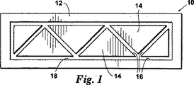
ここで図1を参照すると、従来技術の押出ダイ10の横断面が示されている。押出ダイ10は、外部ダイ部材12及び内部ダイ部材14を含み、これによってダイ壁16が画定されている。ダイ壁16によって溝18が画定されており、これを通って溶融材料が強制的に流される。溶融材料がダイ10から外に強制的に流されると、材料は冷却され、押出部材、例えば図2に横断面で示されている押出部材19が得られる。
Referring now to FIG. 1, a cross section of a prior art extrusion die 10 is shown. The extrusion die 10 includes an
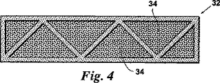
ここで図3を参照すると、改良された押出ダイ20が示されている。押出ダイ20は、外部ダイ部材22及び内部ダイ部材24を含み、これによってダイ壁26が画定されている。ダイ壁26によって溝28が画定されており、これを通って材料が強制的に流される。フォーム又は他の材料のようなコア材料の導入を容易にするための注入流路30が、内部ダイ部材24内に与えられている。したがって、溶融材料は、溝28を通ってダイ20から外に強制的に流され、一方、同時に押出部材にコア材料が充填される。この結果、その中にコア材料34が配置された押出部材32(図4)が得られる。
Referring now to FIG. 3, an improved extrusion die 20 is shown. Extrusion die 20 includes an
ここで図5a〜7bを参照すると、空孔がコア材料34で充填されている複合部材36、38、40、及び42が、図5b、6b、及び7bに示されている。種々の内部支持形状を有する複合部材36、38、40、及び42を押出すことができる。例えば、空孔がコア材料34で充填されている縦支持材42及び斜め支持材44の両方を有する内部構造を有する複合部材36が示されている(図5b)。コア材料34によって充填されている空孔を形成する斜め支持材46を有する複合部材38が示されている(図6b)。コア材料34によって充填されている複数の内部縦支持材48を有する複合部材40が示されている(図7b)。他の形状も可能である。
Referring now to FIGS. 5a-7b,
図8〜11において見られるように、ビーム材がコア材料34によって充填されている種々の内部支持構造を有する複合構造ビーム材50、52、54、及び56が示されている。例えば、内部支持材を有さず、コア材料が充填されているビーム材50が示されている(図8)。斜め支持材58及び直角支持材60を有し、コア材料34によって充填されているビーム材52が示されている(図9)。コア材料34によって充填されている4個の同じ寸法の空孔を画定する第1及び第2の直角支持材62を有するビーム材54が示されている(図10)。コア材料34によって充填されている9個の空孔を画定する4個の直角支持材64を有するビーム材56が示されている(図11)。他の内部支持形状も可能である。
As seen in FIGS. 8-11, composite
一態様、例えば図2及び4の態様においては、ダイ20を通して構造材料を強制的に流しながら、注入流路30を通して注入可能な適合した構造コア材料34を押出ダイ20(図3)中に供給する。押出プロセス中は最適の供給速度を確定しなければならない。一例として、押出部材の構造形状は、1インチ×1インチの寸法及び0.2インチの壁厚を有する典型的な正方形の管である。好ましい押出プロセスにおいては、注入可能な適合した構造コア材料の供給速度は、複合部材に不利に増加した応力を与えることなく最適の特性を可能にするように計算される。一例として、剛性のポリウレタンフォーム又はスチレンフォーム、即ち、Bayerによって製造されているフォームであるBaydur 726 IBSを、注入可能な適合した構造コア材料として用いることができる。以下に議論するように他の材料を用いることもできる。最適の供給速度を計算するためには、以下の段階に従う。
In one embodiment, such as the embodiment of FIGS. 2 and 4, a conformal
第1段階では、液体から固体へのフォームの膨張速度を計算する。フォーム特性に関して以下の仮定を用いることができる。 In the first stage, the expansion rate of the foam from liquid to solid is calculated. The following assumptions can be used regarding the foam properties:
1g=フォームのフリーライズ密度を基準として約4.0cm3;
1g=(4.0cm3(1in3/(2.45cm)3))=0.27in3;
第2段階では、長さフィート基準あたりの充填した空孔容積を計算する。
1 g = about 4.0 cm 3 based on the free rise density of the foam;
1 g = (4.0 cm 3 (1 in 3 /(2.45 cm) 3 )) = 0.27 in 3 ;
In the second stage, the filled void volume per length foot criterion is calculated.
1ft=12in;
1フィートあたりの空孔容積=(12in)(1in)(1in)=12in3;
第3段階では、複合材料1フィートあたりの押出速度を計算する。この計算は装置運転パラメーターに基づく。この例の目的のために、複合材料の押出速度は10ft/分であると仮定する。
1 ft = 12 in;
Pore volume per foot = (12 in) (1 in) (1 in) = 12 in 3 ;
In the third stage, the extrusion rate per foot of composite material is calculated. This calculation is based on equipment operating parameters. For the purposes of this example, assume that the extrusion rate of the composite is 10 ft / min.
第4段階では、複合体の押出速度に適合する非膨張フォームの液体注入速度を決定する。第1段階における膨張の計算値、第2段階における空孔容積の計算値、及び第3段階において計算された押出速度を、第4段階の決定段階において用いる。計算された液体流速によって、体膨張の不適合に起因する膨張及び内部構造内での空孔の生成を全く起こさずに、複合材料によって構造体を充填することが可能になる。第1段階での膨張の計算値、第2段階での計算値、及び第3段階での押出速度によって、複合体の押出速度に適合する非膨張フォームの液体注入速度を計算することが可能になる。 In the fourth step, the liquid injection rate of the non-expanded foam that matches the extrusion rate of the composite is determined. The calculated value of expansion in the first stage, the calculated value of pore volume in the second stage, and the extrusion rate calculated in the third stage are used in the determination stage of the fourth stage. The calculated liquid flow rate allows the structure to be filled with the composite material without causing any expansion due to body expansion mismatch and the creation of vacancies within the internal structure. The calculated value of the expansion in the first stage, the calculated value in the second stage, and the extrusion speed in the third stage make it possible to calculate the liquid injection rate of the unexpanded foam that matches the extrusion speed of the composite. Become.
10ft/分(12in3/1ft)(1g/0.27in3)=444g/分;
1分あたり10フィートの押出板材を充填する444g/分の未反応のフォーム材料の計算された液体流速によって、体膨張の不適合に起因する膨張及び構造複合材料内での空孔の生成を全く起こさずに、複合材料によって構造体を充填することが可能になる。この例は、繊維及び構造充填材を用いないフォームの膨張特性に焦点をあてている。これらは、注入によって物理的容量を変化させないからである。
10ft / min (12in 3 /1ft)(1g/0.27in 3) = 444g / min;
The calculated liquid flow rate of 444 g / min of unreacted foam material filling 10 feet of extruded board per minute caused no expansion due to body expansion mismatch and void formation in the structural composite. Without having to fill the structure with the composite material. This example focuses on the expansion properties of foam without fibers and structural fillers. These are because the physical capacity is not changed by injection.
殆どのフォームは、二成分で反応性が高い。したがって、注入システムを制御するために押出材料と一緒に質量流量調整器又は体積流量調整器を用いて、プロセスを制御したり、或いは任意の時点で停止させることができる。 Most foams are two-component and highly reactive. Thus, the process can be controlled or stopped at any time using a mass flow or volume flow regulator in conjunction with the extruded material to control the injection system.
一態様においては、コア材料34を押出部材の構造空孔又は溝中に手作業で注入し、過剰のコア材料34をプロセスの終了時に切除する。閉止構造体を手作業で充填する場合には、押出部材の内部の注入可能なコア材料34の過度の膨張によって押出部材が変形する可能性がある。注入可能な適合した構造コア材料34としてフォームのような反応性材料を用いることができるが、ゲルのような非反応性材料も本発明の範囲内に含まれると考えられる。
In one aspect, the
ここで表1〜12を参照すると、コア材料を用いるか又は用いない、種々の構造材料及び種々の形状の押出部材に関して応力試験を行った。16インチの間隔を介して離隔されている支持材で厚板材を支持した。それぞれの部材は、5 1/2インチ×1 1/2インチの外側寸法を有している。部材の内部構造部及び壁部は、0.2インチの壁厚を有している。押出部材を、端部を堅く固定することによって固定し、支持材の間の中央部の厚板材の幅全体にわたって、長さ5 1/2インチ×幅1 1/2インチの部材による500lbfの試験負荷にかけた。 Referring now to Tables 1-12, stress tests were performed on various structural materials and various shapes of extruded members with or without a core material. The thick plate material was supported by a support material that was separated by a spacing of 16 inches. Each member has an outer dimension of 5 1/2 inches × 1 1/2 inches. The internal structure and wall of the member have a wall thickness of 0.2 inches. 500 lbf test with a 5 1/2 inch long x 1 1/2 inch wide member across the width of the central plank between the supports, with the extruded member secured by tightly fixing the ends Overloaded.
表1は、モデル1に関する押出部材、即ち縦及び斜めの内部支持部材の両方を有する押出部材(図5a及び5bを参照)に関するデータを示す。押出部材の構造材料は、PolyOne Duraflec LD800ビニル化合物−剛性(RPVC)から構成されている。ケース1においては、コア材料を存在させないで部材を試験した(図5a参照)。表1から明らかなように、試験中に部材において観察された最大撓みは0.0229インチであった。ケース25においては、同じ構造を有するが、Bayer Material Science Baydure STR/C−405IMR、ポリウレタン複合体SRIMフォーム、45%ガラス充填のコア材料を充填した部材において、僅か0.00944の撓みが観察された。ケース45においては、同じ構造を有するが、Bayer Material Science Baydure STR/C−405IMR、ポリウレタン複合体SRIMフォーム、60%ガラス充填のコア材料を充填した部材において、僅か0.00706の撓みが観察された。したがって、フォーム充填構造体によって、増加した撓みに対する抵抗性、即ち、より大きな強度が示されることが分かる。更に、ガラス繊維含量を増加させることによって、撓みの量が更に低下し、即ち部材の強度が更に増加することが分かる。この傾向は、表1〜12のそれぞれを参照することによって、押出部材のそれぞれの幾何形状に関して観察することができる。幾つかの材料及び形状、例えば表2及び9によって示される材料及び形状に関しては、ガラス充填材の割合を増加させることによって向上する特性はごく僅かであった。試験荷重を更に増加させることによって、45%ガラス充填及び60%ガラス充填のフォームを有する部材における強度の差が明らかになるであろうと考えられる。これにより、PVCの壁厚を減少させ、フォームを有する空孔容積を増加させることによって、コスト削減を行うことができることも示される。
Table 1 shows the data for the extruded member for Model 1, ie, the extruded member having both longitudinal and diagonal internal support members (see FIGS. 5a and 5b). The structural material of the extruded member is composed of PolyOne Duraflec LD800 vinyl compound-rigid (RPVC). In case 1, the member was tested without the core material present (see FIG. 5a). As is apparent from Table 1, the maximum deflection observed in the part during the test was 0.0229 inches. In
要約すれば、表1〜12は、コア材料中に繊維を含ませることによって複合部材の増加された強度を達成することができることを示す。 In summary, Tables 1-12 show that increased strength of the composite member can be achieved by including fibers in the core material.
内部コア材料の熱膨張と関係する熱可塑性材料の熱垂れの相互関係を考慮して、特定のプラスチックと共に用いるための理想的なフォームを選択することができる。温度が上昇するにつれて構造部材の内部横材及び外部構造体が機械的脆弱化を起こすので、高い変形温度と共に最適の熱膨張係数(CTE)を有する選択された内部コア材料によって、結合複合体の剛性及び機械的強度が向上するであろう。 The ideal foam for use with a particular plastic can be selected in view of the correlation of the thermal sag of the thermoplastic material relative to the thermal expansion of the inner core material. As the temperature rises, the inner cross member and the outer structure of the structural member become mechanically weakened, so that the selected inner core material with the optimum coefficient of thermal expansion (CTE) along with the high deformation temperature will cause the bonded composite to Stiffness and mechanical strength will be improved.
CTEを制御する一つの方法は、構造充填材を加えることによるものである。例えば、フォームにミクロスフェアを混合して加える。40〜50容量%のガラスミクロスフェアを加えることにより、コア材料の重量が低下し、CTEが約40%〜50%低下する。ガラスミクロスフェアは、ミクロスフェアが剛性の固体である、即ち実質的に非圧縮性であり、ポリウレタンマトリクスの内部で優れた接着性を有するという事実をはじめとする有利な特性を有する。ガラスミクロスフェアは、化学的及び熱的に安定であり、製造法に依存してほぼゼロの吸水性を有する。ガラスミクロスフェアの粒径によって、平滑な表面と共に優れた機械加工性が可能になる。 One way to control CTE is by adding structural fillers. For example, the microspheres are mixed and added to the foam. Adding 40-50% by volume glass microspheres reduces the weight of the core material and reduces the CTE by about 40% -50%. Glass microspheres have advantageous properties, including the fact that the microspheres are rigid solids, i.e., substantially incompressible, and have excellent adhesion within the polyurethane matrix. Glass microspheres are chemically and thermally stable and have nearly zero water absorption depending on the manufacturing method. The glass microsphere particle size enables excellent machinability with a smooth surface.
選択量のガラスミクロスフェアを加えることによって、得られるフォームコアを、構造材料のCTEに対して所望のCTEを有するように調整することが可能になる。公知の材料のCTEの例は、下表Aにおいて見ることができる。 By adding a selected amount of glass microspheres, it is possible to adjust the resulting foam core to have the desired CTE relative to the CTE of the structural material. Examples of CTEs of known materials can be found in Table A below.

以下の実施例においては、構造充填材を用いて、複合コア材料のCTE及び密度を低下させた。下表Bは、ミクロスフェア/フォームの比、及び、異なるミクロスフェア濃度におけるフォーム材料のCTEを示す。 In the following examples, structural fillers were used to reduce the CTE and density of the composite core material. Table B below shows the microsphere / foam ratio and the CTE of the foam material at different microsphere concentrations.
公知のPVC材料、例えばPolyOne Duraflec LD800ビニル化合物−剛性(RPVC)のCTEは、ASTM D696にしたがって61.2μm/m−℃であることが公知である(上表Aから)。直上の表Bは、特定例のフォーム、即ち、構造充填材を加える前に0.88g/ccの密度の出発基準値を有し、90μm/m−℃のCTEを有するBayer Bayder 726IBS剛性ポリウレタンフォームの特性を示す。構造充填材の量を調整することによって、この3.3μm/m−℃のCTEを有する3M Scotchlite Glass Bubblers Kシリーズの場合には、選択量の構造充填材をフォーム中に含ませて、PVC構造材料のCTE及びフォームのCTEを最適にすることのできる得られるフォームを生成させることができる。この例においては、CTEを最適にするのに必要な充填材の量は、30%充填〜40%充填の間である。この例においては、K20ミクロスフェアを用いた40%充填によって、55.5μm/m−℃のフォームCTEが得られる。新しい複合密度は0.608g/ccである。 It is known that the CTE of known PVC materials, eg PolyOne Duraflec LD800 vinyl compound-rigid (RPVC), is 61.2 μm / m- ° C. according to ASTM D696 (from Table A above). Table B directly above is a specific example of a Bayer Bayder 726IBS rigid polyurethane foam having a starting reference value of 0.88 g / cc density and a CTE of 90 [mu] m / m- [deg.] C before adding structural filler. The characteristics of By adjusting the amount of structural filler, in the case of 3M Scotchlite Glass Bubblers K series having this CTE of 3.3 μm / m- ° C., a selected amount of structural filler is included in the foam to create a PVC structure. The resulting foam can be generated that can optimize the CTE of the material and the CTE of the foam. In this example, the amount of filler needed to optimize CTE is between 30% and 40% filling. In this example, 40% loading with K20 microspheres yields a foam CTE of 55.5 μm / m- ° C. The new composite density is 0.608 g / cc.
上記の例は、構造材料及びフォームコアのCTEをどのようにして選択してCTEの差を減少させることができるかを示しているが、構造材料及びフォームコアのCTEの任意の所望の関係を選択して所望の結果を達成することができると考えられる。 The above example shows how the CTE of the structural material and the foam core can be selected to reduce the CTE difference, but any desired relationship between the structural material and the CTE of the foam core is shown. It is believed that it can be selected to achieve the desired result.
ここで図13を参照すると、新しい革新を可能にし、更に複合フォーム104内の構造安定性を更に向上させるために、短繊維102と組み合わせたミクロスフェア100が示されている。発泡剤を変化させることによって、ポリウレタンのセルラーフォーム構造体104を調整することができる。繊維102を存在させることと組み合わせてミクロスフェア100のような固体充填材の影響によって、複合体全体が大きく強化される。例えば、7ミクロンの直径を有する1/8インチの短繊維102を、50容量%のミクロスフェア100及び50容量%のフォーム104の容量比を有するフォーム104の内部に配置することができる。繊維102はミクロスフェア100に接触し、これに接着する。3Mが製造している最も大きなミクロスフェア100は120ミクロンである。したがって、50%固体のフォームマトリクスの内部に1/8インチの繊維102を配すると、5,200個のミクロスフェア100の表面に接触し、これに接着する可能性がある。フォーム材料104はエラストマー性を有しており、固体粒子100は有していない。したがって、固体粒子100は、フォームマトリクス内の繊維102と共に固着システムのように作用し、これにより繊維102が樹脂マトリクスの内部で移動する自由度が制限される。この現象により、剛性を増加させるのに必要な繊維102の量が減少する。これは、微細構造形状の内部の繊維102と相互作用する固体材料100の固着性のためである。
Referring now to FIG. 13, a
上記に記載の方法を用いると、航空宇宙産業の必要性を満足するように構造フォームを調整することができることが分かる。一般に、航空宇宙構造フォーム複合体に関する基準としては、熱安定性及び低いCTE、低い密度及び軽量(10〜15lbs/ft3)、構造的剛性、良好な内部強度、170℃を超える使用温度、機械加工性、閉止セル構造、低い吸水性、制御可能な硬化時間、化学的安定性、エポキシに関する優れた接着性、及び任意の長さに注型成形することができる材料であることが挙げられる。 It can be seen that using the method described above, the structural foam can be adjusted to meet the needs of the aerospace industry. In general, standards for aerospace structural foam composites include thermal stability and low CTE, low density and light weight (10-15 lbs / ft 3 ), structural rigidity, good internal strength, service temperature above 170 ° C., machine Processability, closed cell structure, low water absorption, controllable cure time, chemical stability, excellent adhesion with epoxy, and materials that can be cast to any length.
構造コア材料を航空宇宙用にデザインする場合には、ミクロスフェアは、構造コア材料のCTE及び総合密度を低下させるために高い割合比率、例えば40容量%〜80容量%で加える必要がある。 If the structural core material is designed for aerospace, the microspheres need to be added at a high rate, for example 40% to 80% by volume, to reduce the CTE and overall density of the structural core material.
コア材料全体にわたる機械的寸法安定性を向上させるために必要な場合には少量の繊維添加剤をこのデザインの配合物中に含ませることができる。繊維を加えることの欠点は、繊維の添加によって複合部材の重量が増加することである。したがって、少量の適切に選択された短繊維を用いることができ、即ち、出発点として4〜10質量%の量が所望の構造特性を達成するために十分である。ミクロン範囲の小さな直径を有するガラス短繊維によって、化学的、機械的、及び熱的安定性と共に、低い吸湿性の利益が与えられる。更に、得られる複合体は機械加工することができ、ガラス短繊維によってウレタンとの優れた接着性が与えられる。 Small amounts of fiber additives can be included in this design formulation if necessary to improve mechanical dimensional stability throughout the core material. The disadvantage of adding fibers is that the addition of fibers increases the weight of the composite member. Thus, a small amount of appropriately selected short fibers can be used, ie an amount of 4-10% by weight as a starting point is sufficient to achieve the desired structural properties. Short glass fibers with a small diameter in the micron range provide low hygroscopic benefits along with chemical, mechanical and thermal stability. Furthermore, the resulting composite can be machined, and the short glass fibers provide excellent adhesion with urethane.
上記に記載の方法を用いて、所望の特性を有する複合木材を製造することができる。本発明方法を用いて、170°F以下又はこれよりも高い優れた熱機械的安定性、低い吸湿性、構造材料を減少させることによるコスト削減、製造量を最大にするための制御可能な硬化時間、難燃特性、虫害抵抗性、カビ抵抗性を有し、丸のこで容易に切断することができる複合木材を製造することができる。 Using the method described above, composite wood with the desired properties can be produced. Using the method of the present invention, excellent thermomechanical stability below 170 ° F or higher, low hygroscopicity, cost savings by reducing structural materials, controllable curing to maximize production A composite wood that has time, flame retardancy, insect damage resistance, and mold resistance and can be easily cut with a circular saw can be produced.
ポリウレタン構造フォームは、現在入手することのできる最も費用効率の高いフォームマトリクスである。ポリウレタンフォームは、功を奏することが分かっている添加剤に基づいて、耐炎性、虫害抵抗性、及びカビ抵抗性になるように配合することができる。押出構造化学材料の選択、及びフォームを充填するか又は充填しないかによって、コア材料の構造的完全性が大きく変化する。しかしながら、優れた機械特性及び熱特性のために、ポリエチレン又はポリプロピレンよりもPVC材料が好ましい。 Polyurethane structural foam is the most cost-effective foam matrix currently available. Polyurethane foams can be formulated to be flame resistant, insect resistant, and mold resistant based on additives that have been found to work. Depending on the choice of extruded structural chemical material and whether or not the foam is filled, the structural integrity of the core material varies greatly. However, PVC materials are preferred over polyethylene or polypropylene due to superior mechanical and thermal properties.
コスト削減のために構造添加剤を用いることができる。PVCは耐湿性であり、天然繊維を劣化から保護するので、天然繊維及びガラス短繊維を用いることができる。より高い割合の繊維を用いると、より高い構造的剛性が得られる。50%の麻繊維及び50%のガラスの比を有する30〜50重量%の繊維が好ましい。ガラス繊維は熱的により安定であるが、天然繊維は費用効率がより高い。上記に示した高い繊維比を用いることにより、増加した量の発泡剤を用いることができ、これにより構造的完全性を犠牲にすることなくフォームの密度が低下する。また、ガラスミクロスフェア又はヒュームドシリカのような少量の固体粒子を加えてCTEを調整することもできる。この調整によって、材料を、複合成分の間の最良の機械的熱安定性を均一に促進させるように機能させることが可能になる。 Structural additives can be used to reduce costs. PVC is moisture resistant and protects natural fibers from degradation, so natural fibers and short glass fibers can be used. Using a higher proportion of fibers results in higher structural rigidity. 30-50% by weight fiber with a ratio of 50% hemp fiber and 50% glass is preferred. Glass fibers are more thermally stable, but natural fibers are more cost effective. By using the high fiber ratio shown above, increased amounts of blowing agent can be used, which reduces the density of the foam without sacrificing structural integrity. It is also possible to adjust the CTE by adding a small amount of solid particles such as glass microspheres or fumed silica. This adjustment allows the material to function to uniformly promote the best mechanical thermal stability between the composite components.
フォームプラスチックの場合においては、上述したものと同じ構造強化法を用いることができる。構造充填材及び繊維を、原材料供給装置から押出す前か、或いは発泡剤又は機械的注入ガスと接触させる前の配合工程中において、熱可塑性材料中に導入することができる。機械的注入ガスの場合には、適当な混合比の構造粒子及び繊維を含む加圧ガスの導入を介して構造充填材及び繊維をプラスチック中に含ませることができる。 In the case of foam plastic, the same structural strengthening method as described above can be used. Structural fillers and fibers can be introduced into the thermoplastic material prior to extrusion from the raw material feeder or during the compounding process prior to contact with the blowing agent or mechanical injection gas. In the case of a mechanical injection gas, structural fillers and fibers can be included in the plastic through the introduction of a pressurized gas containing structural particles and fibers in an appropriate mixing ratio.
プラスチックには、また、UV安定剤を含ませることができる。UV安定剤は時間と共に減少する傾向がある。UV安定剤は、プラスチックの全厚にわたって、添加剤としてプラスチック中に含ませることができる。使用においては、UVの攻撃は、通常太陽光からもたらされる。したがって、プラスチック複合体には、内部UV安定性よりも保護UV被覆が必要である。 The plastic can also include a UV stabilizer. UV stabilizers tend to decrease over time. UV stabilizers can be included in the plastic as an additive throughout the entire thickness of the plastic. In use, UV attacks usually come from sunlight. Therefore, plastic composites require a protective UV coating rather than internal UV stability.
優れた耐摩耗性、及び時間と共にUV安定性を損失しないUV被覆を有する滑り止め表面は、特に家庭用デッキにおいて用いるための複合木材厚板材を生成させる方法において用いた場合に、上記に記載の複合系に対する利益となるであろう。滑り止め表面は、砂、ミクロスフェア、又は他の小さな硬質粒子のような充填材を加えることによって形成することができる。これらの粒子は、製造プロセスの異なる領域に加える。第1の適用は、エンボシングホイールの前に微粉被覆を施して、それによって複合体の表面中に小さな粒子を埋封する。次に、過剰の材料を表面から吸い取り、再利用することができる。次に、UV添加剤及び耐摩耗性粒子を含む噴霧塗布シーラントを施すことができる。この被覆は、半透明着色の外観を有しており、これによってエンボス加工された木目に木材の自然の着色外観が与えられる。エンボス加工器具を、木目の特徴に類似した溝を残留させるように配置して、これによって木目パターンにおいて被覆がより厚く且つより暗くなって、実際の木材の外観が模造される。適当な顔料レベルを有する適当な被覆系を選択することによって、木材粒子を複合体中に封止し、且つWPCの一貫しない色変動を均一にすることが促進される。プラスチックは、依然として、被覆が擦過されたり損傷を受けた場合に劇的な色差が起こらないように、基本的な顔料添加剤を必要としている。また、消費者が擦過を封止した場合にその美的木目柄に適合させる擦過修繕システムを提供することも可能である。用いることのできる種々の被覆が存在する。例えば、室温、加熱、及び接触のような種々の硬化性を有するポリウレタン、ポリ尿素、及びアクリル樹脂を用いることができる。 An anti-slip surface having excellent abrasion resistance and a UV coating that does not lose UV stability with time, as described above, particularly when used in a method of producing composite wood planks for use in a home deck. It will be a benefit to the composite system. Non-slip surfaces can be formed by adding fillers such as sand, microspheres, or other small hard particles. These particles are added to different areas of the manufacturing process. The first application is to apply a fine powder coating before the embossing wheel, thereby embedding small particles in the surface of the composite. Excess material can then be blotted from the surface and reused. Next, a spray applied sealant containing UV additives and wear resistant particles can be applied. This coating has a translucent colored appearance, which gives the natural colored appearance of the wood to the embossed wood grain. The embossing tool is placed to leave a groove similar to the grain characteristics, which makes the coating look thicker and darker in the grain pattern, imitating the appearance of actual wood. By selecting an appropriate coating system with an appropriate pigment level, the wood particles are encapsulated in the composite and uniform WPC inconsistent color variation is facilitated. Plastics still require basic pigment additives so that dramatic color differences do not occur if the coating is scratched or damaged. It is also possible to provide a scrub repair system that conforms to the aesthetic grain pattern when the consumer seals the scuff. There are various coatings that can be used. For example, polyurethane, polyurea, and acrylic resin having various curability such as room temperature, heating, and contact can be used.
複合体産業においては、所望の特性を有する構造材料を生成させるのに用いることができる種々の材料が開発されている。フォーム産業においては、フォーム材料を強化するために本発明方法を用いることによって向上させることができる木材それ自体よりも大きな強度を有するフォームを製造することができると期待される。図9は、耐久性の外殻が必要である場合があるか、或いはフォームが耐久性の自己被覆プロセスを有していて、フォームが硬化によってそれ自体の耐久性の外側シェルを生成する場合があることを示している。 In the composite industry, various materials have been developed that can be used to produce structural materials having desired properties. In the foam industry, it is expected that foams with greater strength than wood itself can be produced which can be improved by using the method of the present invention to strengthen the foam material. FIG. 9 illustrates that a durable outer shell may be required, or the foam has a durable self-coating process, and the foam may cure to produce its own durable outer shell. It shows that there is.
而して、本発明は、目的を推進し、上記に記載する目標及び有利性及び本発明に固有の目標及び有利性に到達するように、よく適合される。この開示の目的のために現在好ましい態様を記載したが、多くの変化及び修正が当業者には明らかであろう。かかる変化及び修正は、特許請求の範囲によって規定された本発明の精神内に含まれる。 Thus, the present invention is well adapted to promote the objectives and to reach the goals and advantages described above and the goals and advantages inherent in the present invention. While presently preferred embodiments have been described for purposes of this disclosure, many variations and modifications will be apparent to those skilled in the art. Such changes and modifications are encompassed within the spirit of the invention as defined by the appended claims.
Claims (23)
押出複合部材を強化するための繊維及び実質的に非圧縮性の充填材料を含むコア材料を該空孔に充填し;
該構造材料の熱膨張係数を測定し;そして
該コア材料中の該充填材料の量を調節して、該構造材料に対する該コア材料の所望の熱膨張係数を達成する;
工程を含む、押出複合部材を製造する方法であって、
該コア材料の該所望の熱膨張係数が、該コア材料と該構造材料との間の剪断応力を減少させるように選択される熱膨張係数である、前記方法。Extruding structural material through a die to form an elongated structure having pores defined therein;
Fibers and substantially core material comprising a non-compressible filling material for reinforcing extruded composite member was filled into the air hole;
Measuring the coefficient of thermal expansion of the structural material; and
Adjusting the amount of the filler material in the core material to achieve a desired coefficient of thermal expansion of the core material relative to the structural material;
A method for producing an extruded composite member, comprising the steps of :
The method, wherein the desired coefficient of thermal expansion of the core material is a coefficient of thermal expansion selected to reduce shear stress between the core material and the structural material .
選択量の充填材料をコア材料に加えて、該構造材料に対する該コア材料の所望の熱膨張係数を達成し;
ダイを通して該構造材料を押出して、その中に空孔が画定されている細長い構造体を形成し;
該コア材料を該空孔に充填する;
工程を含む、押出複合部材を製造する方法であって、
該コア材料の該所望の熱膨張係数が、該コア材料と該構造材料との間の剪断応力を減少させるように選択される熱膨張係数である、前記方法。Measuring the coefficient of thermal expansion of the structural material;
A selected amount of filler material is added to the core material to achieve a desired coefficient of thermal expansion of the core material relative to the structural material;
Extruding the structural material through a die to form an elongated structure having pores defined therein;
Filling the pores with the core material;
A method for producing an extruded composite member, comprising the steps of :
The method, wherein the desired coefficient of thermal expansion of the core material is a coefficient of thermal expansion selected to reduce shear stress between the core material and the structural material .
ダイを通して該フォーム材料を押出して細長い部材を形成する;
工程を含む、押出部材を製造する方法。 Including randomly placed short fibers and substantially incompressible filler material in the foam material;
Extruding the foam material through a die to form an elongated member;
A method for producing an extruded member, comprising a step.
ダイを通して該構造材料を押出して、その中に空孔が画定されている細長い構造体を形成し;
該コア材料を該空孔に充填する;
工程を含む、押出複合部材を製造する方法であって、
該コア材料の該所望の熱膨張係数が、該コア材料と該構造材料との間の剪断応力を減少させるように選択される熱膨張係数である、前記方法。A selected amount of filler material is added to the core material to achieve the desired coefficient of thermal expansion of the core material relative to the structural material;
Extruding the structural material through a die to form an elongated structure having pores defined therein;
Filling the pores with the core material;
A method for producing an extruded composite member, comprising the steps of :
The method, wherein the desired coefficient of thermal expansion of the core material is a coefficient of thermal expansion selected to reduce shear stress between the core material and the structural material .
該部材上でエンボシングホイールを回転して、該粒子を該部材中に埋封して滑り止め表面を生成する;
工程を含む、請求項16に記載の方法。Applying a particle coating to the extruded member;
Rotating an embossing wheel on the member to embed the particles in the member to create a non-slip surface;
The method according to claim 16, comprising a step.
施されたシーラントがエンボス加工領域においてより厚くて、天然の木目状に着色された外観を生成する、請求項21に記載の方法。Generating a simulated wood grain pattern by rotating the embossing wheel;
The method of claim 21 , wherein the applied sealant is thicker in the embossed area to produce a natural grained appearance.
Applications Claiming Priority (3)
| Application Number | Priority Date | Filing Date | Title |
|---|---|---|---|
| US70962805P | 2005-08-19 | 2005-08-19 | |
| US60/709,628 | 2005-08-19 | ||
| PCT/US2006/032674 WO2008024107A2 (en) | 2005-08-19 | 2006-08-21 | Method of producing composite members having increased strength |
Related Child Applications (1)
| Application Number | Title | Priority Date | Filing Date |
|---|---|---|---|
| JP2012032868A Division JP5886072B2 (en) | 2005-08-19 | 2012-02-17 | Method for manufacturing a composite member having increased strength |
Publications (2)
| Publication Number | Publication Date |
|---|---|
| JP2009504462A JP2009504462A (en) | 2009-02-05 |
| JP4947052B2 true JP4947052B2 (en) | 2012-06-06 |
Family
ID=39043174
Family Applications (2)
| Application Number | Title | Priority Date | Filing Date |
|---|---|---|---|
| JP2008531125A Active JP4947052B2 (en) | 2005-08-19 | 2006-08-21 | Method for manufacturing a composite member having increased strength |
| JP2012032868A Expired - Fee Related JP5886072B2 (en) | 2005-08-19 | 2012-02-17 | Method for manufacturing a composite member having increased strength |
Family Applications After (1)
| Application Number | Title | Priority Date | Filing Date |
|---|---|---|---|
| JP2012032868A Expired - Fee Related JP5886072B2 (en) | 2005-08-19 | 2012-02-17 | Method for manufacturing a composite member having increased strength |
Country Status (16)
| Country | Link |
|---|---|
| US (3) | US20070045886A1 (en) |
| EP (1) | EP1928643B1 (en) |
| JP (2) | JP4947052B2 (en) |
| KR (1) | KR101434338B1 (en) |
| CN (1) | CN101405125A (en) |
| AU (1) | AU2006347551A1 (en) |
| BR (1) | BRPI0615353A2 (en) |
| CA (1) | CA2627367C (en) |
| DK (1) | DK1928643T3 (en) |
| ES (1) | ES2902945T3 (en) |
| IL (1) | IL189582A (en) |
| MX (1) | MX2008002396A (en) |
| NO (1) | NO20081413L (en) |
| NZ (2) | NZ566776A (en) |
| RU (2) | RU2432258C2 (en) |
| WO (1) | WO2008024107A2 (en) |
Families Citing this family (18)
| Publication number | Priority date | Publication date | Assignee | Title |
|---|---|---|---|---|
| US7427172B2 (en) * | 2006-03-31 | 2008-09-23 | Champagne Editions, Inc. | Temporary roadway element |
| US20090278271A1 (en) * | 2008-05-08 | 2009-11-12 | Wolfe Jason L | Thermal Revitalization of Polymer-Containing Materials |
| WO2012122063A1 (en) * | 2011-03-04 | 2012-09-13 | Brockwell Michael Ian | Exotensioned structural members with energy-absorbing effects |
| FR2989303B1 (en) * | 2012-04-11 | 2015-02-13 | Alphacan Sa | COMPOSITE MATERIAL FOR BOARDS INTENDED FOR OUTDOOR FITTING |
| US20140018502A1 (en) | 2012-07-15 | 2014-01-16 | Ronald Matthew Sherga | Thermoformed Structural Composites |
| WO2014062179A1 (en) | 2012-10-17 | 2014-04-24 | Ecopuro, Llc | Enhanced boundary layer heat transfer by particle interaction |
| DE102013022247B4 (en) * | 2013-12-09 | 2019-01-24 | Audi Ag | Vehicle body element |
| US10343328B1 (en) | 2014-01-31 | 2019-07-09 | Ecostrate Sfs, Inc. | Structural composites method and system |
| RU2605909C1 (en) * | 2015-06-09 | 2016-12-27 | Общество с ограниченной ответственностью "ПЛАСТГРАУНД" | Profiled structural element and method of its production |
| CA3016267A1 (en) * | 2016-03-15 | 2017-09-21 | Tech Plas Extrusions Pty Ltd | A scaffold board |
| WO2017180603A1 (en) * | 2016-04-15 | 2017-10-19 | Cc3D Llc | Head and system for continuously manufacturing composite hollow structure |
| US10919665B2 (en) * | 2016-10-06 | 2021-02-16 | Viking Cold Solutions, Inc. | Pallet with thermal energy storage |
| CN110126234A (en) * | 2018-02-09 | 2019-08-16 | 万亿运营(深圳)科技有限责任公司 | A kind of filled type plastic box body panel and its production method |
| DE102018122797A1 (en) * | 2018-09-18 | 2020-03-19 | Kraussmaffei Technologies Gmbh | Device for molding a plastic component |
| KR102024651B1 (en) * | 2018-10-24 | 2019-09-24 | 주식회사 현대엘앤씨 | Method for manufacturing profile for polyvinyl chloride window with real wood texture |
| CN109551738B (en) * | 2019-01-28 | 2020-03-06 | 重庆西亚新型装饰材料有限公司 | Fireproof cold-resistant heat-preservation aluminum-plastic plate and production system and preparation method thereof |
| KR102256735B1 (en) * | 2019-06-25 | 2021-05-27 | 휴인 주식회사 | Manufacturing method of anti-slip type board and anti-slip type board produced therefrom |
| CN112331375B (en) * | 2020-11-23 | 2022-09-20 | 四川玄武岩纤维新材料研究院(创新中心) | Fiber honeycomb fabric nuclear shielding composite material and preparation method and application thereof |
Family Cites Families (82)
| Publication number | Priority date | Publication date | Assignee | Title |
|---|---|---|---|---|
| US2857879A (en) * | 1955-09-01 | 1958-10-28 | Abrasive Company Of America | Apparatus for preparing abrasive articles |
| DE1154264B (en) * | 1956-11-20 | 1963-09-12 | Reifenhaeuser Kg | Device for the continuous extrusion of molded bodies with a foam core and a shell made of thermoplastic material |
| US3192294A (en) | 1962-06-21 | 1965-06-29 | Us Rubber Co | Method of molding vinyl resin sheet material having an embossed surface |
| US3274315A (en) | 1963-02-25 | 1966-09-20 | Tokan Kogyo Co Ltd | Process for unitized construction of synthetic resin board or cylinder |
| DE1504444B1 (en) * | 1963-03-04 | 1972-03-16 | Yuzo Kawamura | METHOD FOR CONTINUOUS MANUFACTURING OF PLASTIC PANELS WITH VACUUMS EXTENDING IN THE MANUFACTURING DIRECTION AND DEVICE FOR CARRYING OUT THE PROCESS |
| US3668288A (en) | 1968-11-18 | 1972-06-06 | Keiichi Takahashi | Method for making thermoplastic synthetic resin hollow structure articles |
| US3881984A (en) | 1969-08-07 | 1975-05-06 | Sekisui Plastics | Apparatus for preparation of synthetic wood |
| US3644168A (en) * | 1970-06-12 | 1972-02-22 | Upjohn Co | Varied density polyisocyanurate foam structure |
| DE2147876C3 (en) | 1970-09-29 | 1975-04-24 | Tokan Kogyo Co. Ltd., Tokio | Method and device for manufacturing hollow sheet products from thermoplastic synthetic resin |
| US3764245A (en) | 1971-05-10 | 1973-10-09 | F Miyamoto | Apparatus for producing light structural board of thermoplastic resin |
| HU171338B (en) | 1971-11-23 | 1977-12-28 | Roemmler H Resopal Werk Gmbh | Method for producing fibreglass reinforced plastic shaped bodies |
| US4211848A (en) * | 1972-06-14 | 1980-07-08 | Blount David H | Process for the production of polyisocyanate-polyester-silicate plastic |
| US3935357A (en) | 1973-03-27 | 1976-01-27 | I. S. A. P. S.P.A. | Hollow extruded plastic strips for packings |
| JPS5030958A (en) | 1973-07-18 | 1975-03-27 | ||
| US3888647A (en) | 1974-04-15 | 1975-06-10 | Maul Bros Inc | Air cooled annular parison blank mold |
| US4377646A (en) | 1975-04-14 | 1983-03-22 | Blount David H | Process for the production of foamed poly(epoxy-polyisocyanate)silicate polymers |
| US3957250A (en) | 1975-04-14 | 1976-05-18 | Murphy Stanley E | Plastic fence post |
| US4082702A (en) | 1975-09-18 | 1978-04-04 | Dow Corning Corporation | Flame retardant rigid polyurethane syntactic foam |
| DE2827851A1 (en) * | 1978-06-24 | 1980-03-27 | Schock & Co Gmbh | CONSTRUCTION PROFILE BAR, ESPECIALLY PROFILE BAR FOR THE PRODUCTION OF WINDOW FRAMES |
| US4304080A (en) | 1980-01-28 | 1981-12-08 | The Budd Company | Construction beam |
| US4344381A (en) * | 1980-12-29 | 1982-08-17 | Allied Tube & Conduit Corporation | Apparatus for continuously electrostatically coating an elongated object |
| US4403502A (en) * | 1981-03-04 | 1983-09-13 | University Of Pittsburgh | Viscometer for cast foaming materials and associated method |
| JPS59140034A (en) | 1983-01-05 | 1984-08-11 | Fukubi Kagaku Kogyo Kk | Synthetic resin molding filled with fibrous reinforcing foam and continuous manufacture thereof |
| US4602765A (en) | 1984-04-23 | 1986-07-29 | Loper Karl J | Fencing assembly and process |
| US4595623A (en) * | 1984-05-07 | 1986-06-17 | Hughes Aircraft Company | Fiber-reinforced syntactic foam composites and method of forming same |
| SU1305051A1 (en) * | 1985-11-14 | 1987-04-23 | Институт Физической Химии Им.Л.В.Писаржевского | Method for continuous manufacture of hollow articles from reinforced materials and device for effecting same |
| JPH0777763B2 (en) | 1986-05-12 | 1995-08-23 | 川崎重工業株式会社 | Beam-shaped structural members reinforced with fibers |
| US4837251A (en) * | 1988-02-08 | 1989-06-06 | Sundstrand Corporation | Dimensionally-stable lightweight core for composite structures |
| US4978562A (en) | 1990-02-05 | 1990-12-18 | Mpa Diversified Products, Inc. | Composite tubular door beam reinforced with a syntactic foam core localized at the mid-span of the tube |
| JPH04170440A (en) | 1990-11-01 | 1992-06-18 | Mitsubishi Petrochem Co Ltd | Production of plastic foam |
| US5707571A (en) * | 1991-03-28 | 1998-01-13 | Reedy; Michael Edward | Process for producing fiber reinforced foam having a random orientations of fibers |
| DE9110957U1 (en) | 1991-09-04 | 1991-11-07 | Degussa | |
| US5253458A (en) | 1992-02-21 | 1993-10-19 | Dean Christian | Simulated log and panel prefabricated house structure |
| US5804353A (en) * | 1992-05-11 | 1998-09-08 | E. I. Dupont De Nemours And Company | Lasers engravable multilayer flexographic printing element |
| US5412915A (en) | 1993-01-19 | 1995-05-09 | Johnson; Richard D. | Dock plank assembly |
| US5783125A (en) * | 1993-04-05 | 1998-07-21 | Crane Plastics Company Limited Partnership | Reinforced extrusion products and method of making same |
| US5613339A (en) * | 1993-12-01 | 1997-03-25 | Heritage Vinyl Products, Inc. | Deck plank and cover |
| US6735916B2 (en) | 1994-03-25 | 2004-05-18 | Mouchel Consulting Limited | Reinforced structural member |
| US6226944B1 (en) | 1994-03-25 | 2001-05-08 | Mouchel Consulting Limited | Reinforced structural member |
| US5665284A (en) | 1995-04-26 | 1997-09-09 | Ronald D. Erwin | Process for manufacturing foam-filled extruded products |
| US5713165A (en) | 1995-04-26 | 1998-02-03 | Erwin Industries, Inc. | Foam-filled extruded plastic decking with non-slip surface coating |
| US6165588A (en) | 1998-09-02 | 2000-12-26 | Henkel Corporation | Reinforcement of hollow sections using extrusions and a polymer binding layer |
| US6027798A (en) * | 1995-11-01 | 2000-02-22 | The Boeing Company | Pin-reinforced sandwich structure |
| US5658644A (en) | 1995-12-05 | 1997-08-19 | Inteplast Corporation | Light weight board of improved mechanical strength and manufacture thereof |
| US5783286A (en) | 1996-04-04 | 1998-07-21 | Dinicola; James L. | Hollow-core plastic structural lumber alternative |
| DE19643828A1 (en) * | 1996-10-30 | 1998-05-07 | Bayer Ag | Surface treatment of thermoplastic sheets |
| EP0890423A4 (en) * | 1996-12-26 | 2002-01-30 | Sekisui Chemical Co Ltd | Foamable thermoplastic sheet-like synthetic resin, thermoplastic foamed resin and their production method |
| AU5037698A (en) * | 1997-02-17 | 1998-08-20 | Ricegrowers' Co-Operative Limited | Continuous extrusion process using organic waste materials |
| US5953878A (en) | 1997-06-06 | 1999-09-21 | S.S.D. Control Technology, Inc. | Polyvinyl deck |
| US5830395A (en) * | 1997-08-12 | 1998-11-03 | E. I. Du Pont De Nemours And Company | Process for making a uniform dispersion of aramid fibers and polymer |
| US6054197A (en) | 1997-09-19 | 2000-04-25 | State University Of New York At Albany | Structural elements |
| US5972475A (en) | 1997-10-24 | 1999-10-26 | The Dow Chemical Company | Structural sheet design for reduced weight and increased rigidity |
| US6233892B1 (en) | 1997-10-25 | 2001-05-22 | The Namlyt Company | Structural panel system |
| AUPP361898A0 (en) | 1998-05-20 | 1998-06-11 | Starlon Pty Ltd | Extrusion |
| TW523531B (en) * | 1998-06-30 | 2003-03-11 | Bayer Ag | Mouldings provided with a water-spreading coating and process for producing them |
| US6103784A (en) * | 1998-08-27 | 2000-08-15 | Henkel Corporation | Corrosion resistant structural foam |
| US6818163B1 (en) * | 1999-02-12 | 2004-11-16 | Dow Global Technologies Inc. | Nanocomposite articles and process for making |
| JP2000239466A (en) * | 1999-02-25 | 2000-09-05 | Mitsubishi Plastics Ind Ltd | Woodgrain pattern-forming thermoplastic resin composition and woodgrain patterned molded product |
| US6347494B1 (en) | 1999-03-12 | 2002-02-19 | Cw Ohio, Inc. | Wood filled plastic building members and method of manufacture |
| NZ503189A (en) | 1999-04-08 | 2001-02-23 | Premark Rwp Holdings Inc | Thermoplastic acrylic sheet compositions comprising PMMA and their use as substitutes for high pressure decorative laminate |
| AU5159600A (en) | 1999-05-28 | 2000-12-18 | Hi-Tech Environmental Products, Llc. | Synthetic thermoplastic compositions and articles made therefrom |
| DE50001317D1 (en) * | 1999-09-23 | 2003-04-03 | Arova Schaffhausen Ag Schaffha | Composite with fibers embedded in a thermoplastic matrix |
| US6673415B1 (en) * | 1999-11-26 | 2004-01-06 | Sanyo Chemical Industries, Ltd. | Honeycomb core material for sandwich structure and method for manufacturing the same |
| US7169460B1 (en) | 1999-12-14 | 2007-01-30 | Mannington Mills, Inc. | Thermoplastic planks and methods for making the same |
| US6301842B1 (en) | 1999-12-22 | 2001-10-16 | Dayton Technologies, L.L.C. | Deck assembly |
| CN100413680C (en) * | 2000-09-11 | 2008-08-27 | 范蒂科股份公司 | Seamless model and method of making a seamless model |
| US6403222B1 (en) | 2000-09-22 | 2002-06-11 | Henkel Corporation | Wax-modified thermosettable compositions |
| US20040148965A1 (en) * | 2001-01-19 | 2004-08-05 | Crane Plastics Company Llc | System and method for directing a fluid through a die |
| US7186102B2 (en) * | 2001-04-26 | 2007-03-06 | Strandex Corporation | Apparatus and method for low-density cellular wood plastic composites |
| US6759114B2 (en) | 2001-10-27 | 2004-07-06 | Inteplast Group, Ltd | Light weight board of improved surface flatness and process for production thereof |
| US6756426B2 (en) | 2001-12-20 | 2004-06-29 | I-Tek, Inc. | Lightweight composite material for protective pads, cushions, supports or the like and method |
| DE60312487T2 (en) | 2002-01-15 | 2008-01-03 | Vkr Holding A/S | USE OF A COMPOSITION FOR COATING AT LEAST ONE PART OF A SURFACE OF A NATURAL RESIN CONTAINING WOODEN SUBSTRATE |
| US6931803B1 (en) | 2002-03-08 | 2005-08-23 | Gary Davis | Modular building system |
| US6972144B2 (en) * | 2002-04-19 | 2005-12-06 | Hunter Paine Enterprises, Llc | Composite structural material and method of making same |
| WO2003097349A1 (en) | 2002-05-15 | 2003-11-27 | W. R. Grace & Co. Conn | Skid resistant moisture barriers and process for making same |
| US7335399B2 (en) * | 2002-09-06 | 2008-02-26 | Grafted Coatings, Inc. | Process for imparting a wood color and grain to a substrate |
| US6844040B2 (en) | 2002-10-01 | 2005-01-18 | Arunas Antanas Pabedinskas | Reinforced composite structural members |
| US7247673B2 (en) * | 2003-04-30 | 2007-07-24 | National Starch And Chemical Investment Holding Corporation | Waterbased high abrasion resistant coating |
| CA2445094A1 (en) | 2003-10-15 | 2005-04-15 | Royal Group Technologies Limited | Extruded foam plastic frame members |
| US7763341B2 (en) | 2004-01-23 | 2010-07-27 | Century-Board Usa, Llc | Filled polymer composite and synthetic building material compositions |
| MX2007000943A (en) * | 2004-07-30 | 2007-04-13 | Mannington Mills | Flooring products and methods of making the same. |
| US7635731B2 (en) | 2005-07-28 | 2009-12-22 | Chemtura Corporation | Cellulosic-thermoplastic composite and method of making the same |
-
2006
- 2006-08-21 NZ NZ566776A patent/NZ566776A/en not_active IP Right Cessation
- 2006-08-21 AU AU2006347551A patent/AU2006347551A1/en not_active Abandoned
- 2006-08-21 EP EP06851817.4A patent/EP1928643B1/en active Active
- 2006-08-21 US US11/507,358 patent/US20070045886A1/en not_active Abandoned
- 2006-08-21 RU RU2008110503/05A patent/RU2432258C2/en active
- 2006-08-21 NZ NZ592862A patent/NZ592862A/en not_active IP Right Cessation
- 2006-08-21 CA CA2627367A patent/CA2627367C/en active Active
- 2006-08-21 BR BRPI0615353-4A patent/BRPI0615353A2/en not_active IP Right Cessation
- 2006-08-21 JP JP2008531125A patent/JP4947052B2/en active Active
- 2006-08-21 MX MX2008002396A patent/MX2008002396A/en active IP Right Grant
- 2006-08-21 KR KR1020087006697A patent/KR101434338B1/en active IP Right Grant
- 2006-08-21 WO PCT/US2006/032674 patent/WO2008024107A2/en active Application Filing
- 2006-08-21 ES ES06851817T patent/ES2902945T3/en active Active
- 2006-08-21 CN CNA2006800393019A patent/CN101405125A/en active Pending
- 2006-08-21 DK DK06851817.4T patent/DK1928643T3/en active
-
2008
- 2008-02-18 IL IL189582A patent/IL189582A/en active IP Right Grant
- 2008-03-18 NO NO20081413A patent/NO20081413L/en not_active Application Discontinuation
-
2011
- 2011-05-19 US US13/111,680 patent/US10357906B2/en active Active
- 2011-06-09 RU RU2011123589/05A patent/RU2011123589A/en not_active Application Discontinuation
-
2012
- 2012-02-17 JP JP2012032868A patent/JP5886072B2/en not_active Expired - Fee Related
-
2019
- 2019-01-12 US US16/246,477 patent/US20190322010A1/en not_active Abandoned
Also Published As
| Publication number | Publication date |
|---|---|
| AU2006347551A1 (en) | 2008-02-28 |
| NZ566776A (en) | 2011-12-22 |
| US20190322010A1 (en) | 2019-10-24 |
| MX2008002396A (en) | 2008-11-10 |
| RU2008110503A (en) | 2009-09-27 |
| CA2627367A1 (en) | 2008-02-28 |
| CA2627367C (en) | 2016-10-11 |
| DK1928643T3 (en) | 2022-01-10 |
| KR20080068804A (en) | 2008-07-24 |
| KR101434338B1 (en) | 2014-08-28 |
| US20070045886A1 (en) | 2007-03-01 |
| WO2008024107A2 (en) | 2008-02-28 |
| EP1928643B1 (en) | 2021-12-15 |
| NO20081413L (en) | 2008-05-15 |
| JP2009504462A (en) | 2009-02-05 |
| JP2012166553A (en) | 2012-09-06 |
| BRPI0615353A2 (en) | 2011-05-17 |
| IL189582A (en) | 2016-04-21 |
| EP1928643A2 (en) | 2008-06-11 |
| US10357906B2 (en) | 2019-07-23 |
| JP5886072B2 (en) | 2016-03-16 |
| NZ592862A (en) | 2012-12-21 |
| ES2902945T3 (en) | 2022-03-30 |
| WO2008024107A3 (en) | 2008-10-16 |
| US20110268876A1 (en) | 2011-11-03 |
| RU2432258C2 (en) | 2011-10-27 |
| CN101405125A (en) | 2009-04-08 |
| RU2011123589A (en) | 2012-12-20 |
Similar Documents
| Publication | Publication Date | Title |
|---|---|---|
| JP4947052B2 (en) | Method for manufacturing a composite member having increased strength | |
| EP3245249B1 (en) | Covering panel and process of producing covering panels | |
| CA2572965A1 (en) | Flooring products and methods of making the same | |
| CN103906802B (en) | The heatproof styrol copolymer that can expand | |
| TW201532826A (en) | Honeycomb structures comprising poly(meth)acrylimide foam | |
| WO2017121499A1 (en) | Covering panel and process of producing covering panels | |
| CA2557969A1 (en) | Composite decking | |
| US7332115B2 (en) | Composite material for vehicle hulls and a hull molding process | |
| JP6447670B2 (en) | Fender and method for producing fender | |
| JP3626112B2 (en) | Wood / thermoplastic resin composite foam molded article whose surface is ground and painted and method for producing the same | |
| AU2012201698B2 (en) | Method of producing composite members having increased strength | |
| WO2017217519A1 (en) | Decorative member and decorative member manufacture method | |
| BR132012008657E2 (en) | method for producing composite members with increased strength | |
| JP4591180B2 (en) | Flooring | |
| JP2005279976A (en) | Laminated extruded molding and its manufacturing method | |
| JPH10231613A (en) | Floor member and apartment house built by using the same | |
| JP2005042453A (en) | Flooring | |
| JP2003184289A (en) | Floorboard | |
| JP5092437B2 (en) | Floor construction method and floor | |
| JP2000282671A (en) | Floor material | |
| MXPA06010465A (en) | Composite decking |
Legal Events
| Date | Code | Title | Description |
|---|---|---|---|
| A621 | Written request for application examination |
Free format text: JAPANESE INTERMEDIATE CODE: A621 Effective date: 20090818 |
|
| A977 | Report on retrieval |
Free format text: JAPANESE INTERMEDIATE CODE: A971007 Effective date: 20110617 |
|
| A131 | Notification of reasons for refusal |
Free format text: JAPANESE INTERMEDIATE CODE: A131 Effective date: 20110622 |
|
| RD04 | Notification of resignation of power of attorney |
Free format text: JAPANESE INTERMEDIATE CODE: A7424 Effective date: 20110914 |
|
| A601 | Written request for extension of time |
Free format text: JAPANESE INTERMEDIATE CODE: A601 Effective date: 20110920 |
|
| A602 | Written permission of extension of time |
Free format text: JAPANESE INTERMEDIATE CODE: A602 Effective date: 20110928 |
|
| A601 | Written request for extension of time |
Free format text: JAPANESE INTERMEDIATE CODE: A601 Effective date: 20111020 |
|
| A602 | Written permission of extension of time |
Free format text: JAPANESE INTERMEDIATE CODE: A602 Effective date: 20111027 |
|
| A601 | Written request for extension of time |
Free format text: JAPANESE INTERMEDIATE CODE: A601 Effective date: 20111121 |
|
| A602 | Written permission of extension of time |
Free format text: JAPANESE INTERMEDIATE CODE: A602 Effective date: 20111129 |
|
| A521 | Request for written amendment filed |
Free format text: JAPANESE INTERMEDIATE CODE: A523 Effective date: 20111222 |
|
| TRDD | Decision of grant or rejection written | ||
| A01 | Written decision to grant a patent or to grant a registration (utility model) |
Free format text: JAPANESE INTERMEDIATE CODE: A01 Effective date: 20120120 |
|
| A01 | Written decision to grant a patent or to grant a registration (utility model) |
Free format text: JAPANESE INTERMEDIATE CODE: A01 |
|
| A711 | Notification of change in applicant |
Free format text: JAPANESE INTERMEDIATE CODE: A711 Effective date: 20120213 |
|
| A61 | First payment of annual fees (during grant procedure) |
Free format text: JAPANESE INTERMEDIATE CODE: A61 Effective date: 20120220 |
|
| A521 | Request for written amendment filed |
Free format text: JAPANESE INTERMEDIATE CODE: A821 Effective date: 20120213 |
|
| FPAY | Renewal fee payment (event date is renewal date of database) |
Free format text: PAYMENT UNTIL: 20150316 Year of fee payment: 3 |
|
| R150 | Certificate of patent or registration of utility model |
Free format text: JAPANESE INTERMEDIATE CODE: R150 Ref document number: 4947052 Country of ref document: JP Free format text: JAPANESE INTERMEDIATE CODE: R150 |
|
| R250 | Receipt of annual fees |
Free format text: JAPANESE INTERMEDIATE CODE: R250 |
|
| R250 | Receipt of annual fees |
Free format text: JAPANESE INTERMEDIATE CODE: R250 |
|
| R250 | Receipt of annual fees |
Free format text: JAPANESE INTERMEDIATE CODE: R250 |
|
| R250 | Receipt of annual fees |
Free format text: JAPANESE INTERMEDIATE CODE: R250 |
|
| R250 | Receipt of annual fees |
Free format text: JAPANESE INTERMEDIATE CODE: R250 |
|
| R250 | Receipt of annual fees |
Free format text: JAPANESE INTERMEDIATE CODE: R250 |
|
| R250 | Receipt of annual fees |
Free format text: JAPANESE INTERMEDIATE CODE: R250 |
|
| R250 | Receipt of annual fees |
Free format text: JAPANESE INTERMEDIATE CODE: R250 |
|
| R250 | Receipt of annual fees |
Free format text: JAPANESE INTERMEDIATE CODE: R250 |
|
| R250 | Receipt of annual fees |
Free format text: JAPANESE INTERMEDIATE CODE: R250 |