JP4944388B2 - RF induction lamp with reduced electromagnetic interference - Google Patents
RF induction lamp with reduced electromagnetic interference Download PDFInfo
- Publication number
- JP4944388B2 JP4944388B2 JP2005120097A JP2005120097A JP4944388B2 JP 4944388 B2 JP4944388 B2 JP 4944388B2 JP 2005120097 A JP2005120097 A JP 2005120097A JP 2005120097 A JP2005120097 A JP 2005120097A JP 4944388 B2 JP4944388 B2 JP 4944388B2
- Authority
- JP
- Japan
- Prior art keywords
- winding
- core
- lamp
- electrodeless fluorescent
- lead wires
- Prior art date
- Legal status (The legal status is an assumption and is not a legal conclusion. Google has not performed a legal analysis and makes no representation as to the accuracy of the status listed.)
- Expired - Fee Related
Links
Images


Classifications
-
- H—ELECTRICITY
- H01—ELECTRIC ELEMENTS
- H01J—ELECTRIC DISCHARGE TUBES OR DISCHARGE LAMPS
- H01J65/00—Lamps without any electrode inside the vessel; Lamps with at least one main electrode outside the vessel
- H01J65/04—Lamps in which a gas filling is excited to luminesce by an external electromagnetic field or by external corpuscular radiation, e.g. for indicating plasma display panels
- H01J65/042—Lamps in which a gas filling is excited to luminesce by an external electromagnetic field or by external corpuscular radiation, e.g. for indicating plasma display panels by an external electromagnetic field
- H01J65/048—Lamps in which a gas filling is excited to luminesce by an external electromagnetic field or by external corpuscular radiation, e.g. for indicating plasma display panels by an external electromagnetic field the field being produced by using an excitation coil
Landscapes
- Physics & Mathematics (AREA)
- Engineering & Computer Science (AREA)
- Plasma & Fusion (AREA)
- Electromagnetism (AREA)
- Discharge Lamps And Accessories Thereof (AREA)
- Circuit Arrangements For Discharge Lamps (AREA)
- Non-Portable Lighting Devices Or Systems Thereof (AREA)
Description
本発明は無電極蛍光ランプに関する。より詳細には、商業および住宅の市場に適した、電磁干渉(EMI)が低減されている無電極蛍光ランプに関する。 The present invention relates to an electrodeless fluorescent lamp. More particularly, it relates to an electrodeless fluorescent lamp with reduced electromagnetic interference (EMI) suitable for the commercial and residential markets.
無電極蛍光ランプでは一般的に、ランプの動作中に発生したEMIから周辺領域を保護するために設計された特別な固定部に取り付けることが必要である。このような固定部はファラデー遮蔽部として作用し、これによってランプは、隣接する装置に対して障害を与えることなく動作することができる。しかしこのような特別な固定部によって、ランプを使用できる場所が制限されてしまう。 Electrodeless fluorescent lamps generally need to be attached to special fixtures designed to protect the surrounding area from EMI generated during lamp operation. Such a fixed part acts as a Faraday shield so that the lamp can operate without disturbing adjacent devices. However, the place where the lamp can be used is limited by such a special fixing portion.
現在の幾つかのランプでは、前記問題を種々の手段によって解決する試みがなされている。そのうちの1つは、EMI遮蔽部をランプエンベロープに取り付ける手段を含んでいる。このEMI遮蔽部は、ランプのレンズ部分の内側表面上に取り付けられた透明な導電性コーティングと、該ランプエンベロープの同一側の外側表面上に設けられた不透明な金属コーティングとを組み合わせた形態で構成されている。これらのコーティングは、該ランプの局部グラウンドに電気的に接続されている。このようなシステムはランプのコストを著しく増大させ、ランプの効率を低減し、実際にはPARランプにしか適していない。 Some current lamps have attempted to solve the problem by various means. One of them includes means for attaching the EMI shield to the lamp envelope. The EMI shield is configured with a combination of a transparent conductive coating mounted on the inner surface of the lens portion of the lamp and an opaque metal coating provided on the outer surface on the same side of the lamp envelope. Has been. These coatings are electrically connected to the local ground of the lamp. Such a system significantly increases lamp costs, reduces lamp efficiency, and is actually only suitable for PAR lamps.
別のアプローチがUS4710678に開示されており、このアプローチは、ランプのフェライトコアに捲回された1次巻き線の間に散在している2次巻き線を使用する。この第2の巻き線の一方の端部は自由端部であり、他方の端部は、1次巻き線の一方の端部に接続されている。給電幹線における干渉電流はこのアプローチによって大幅に抑圧されると、主張されている。 Another approach is disclosed in US 4,710,678, which uses secondary windings that are interspersed between the primary windings wound on the ferrite core of the lamp. One end of the second winding is a free end, and the other end is connected to one end of the primary winding. It is argued that the interference current in the feeder mains is greatly suppressed by this approach.
無電極蛍光ランプのEMIを低コストでさらに改善して、住宅および商業の適用事例でさらに使用できるようになれば、この分野における前進となる。
したがって本発明の課題は、従来技術の欠点を解消し、無電極蛍光ランプを改善し、無電極蛍光ランプの効率を向上させ、従来技術のランプの複雑な遮蔽手段を使用せずにEMIフリーの無電極蛍光ランプを実現するランプ構成を提供することである。 Therefore, the object of the present invention is to eliminate the disadvantages of the prior art, improve the electrodeless fluorescent lamp, improve the efficiency of the electrodeless fluorescent lamp, and eliminate the EMI-free without using the complex shielding means of the prior art lamp. It is to provide a lamp configuration that realizes an electrodeless fluorescent lamp.
前記課題は、エンベロープ内にチャンバを設け、該チャンバ内に磁性材料のコアを設け、高周波電源に取り付けられた第1の導入線および第2の導入線を有する第1の巻き線と第2の巻き線とによって該コアを包囲し、該第2の巻き線の各1巻きを該第1の各1巻きに隣接させて該第1の巻き線から絶縁し、一方の側面では、該第2の巻き線の一方の端部を自由端部として他方の端部を前記導入線のうち1つに接続し、他方の導入線を、接地され編組されたスリーブにより包囲することによって解決される。他方では、該第1の巻き線および第2の巻き線を2本巻きとして等しい長さとし、該第2の巻き線の一方の端部を該第1の巻き線の導入線のうち一方に接続することによって解決される。 The object is to provide a first winding and a second winding having a first lead wire and a second lead wire attached to a high-frequency power source by providing a chamber in the envelope, providing a core of magnetic material in the chamber. The core is surrounded by a winding and each winding of the second winding is adjacent to the first winding and insulated from the first winding, and on one side the second winding One end of the winding is connected to one of the lead wires while the other end is connected to one of the lead wires, and the other lead wire is surrounded by a grounded and braided sleeve. On the other hand, the first winding and the second winding are equal in length with two windings, and one end of the second winding is connected to one of the introduction wires of the first winding. It is solved by doing.
前記課題は本発明の1つの側面では、無電極蛍光ランプのランプエンベロープ内部に、磁性材料のコアを有するチャンバを設け、第1の巻き線によって該コアを包囲し、該第1の巻き線に第1の高温の導入線および第2の導入線を設け、前記第1の導入線を電圧供給部の高周波端部に取り付け、前記第2の導入線をRF電圧供給部の局部グラウンドに接続することによって解決される。第2の巻き線は該コアを包囲し、該第2の巻き線の各1巻きが該第1の巻き線の1巻きに隣接して位置付けられ、該第1の巻き線と電気的に絶縁されている。第2の巻き線の一方の端部は自由端部であり、他方の端部は、第1の巻き線の接地された導入線のうち1つに接続されている。接地され編組されたスリーブが、第1の巻き線の高温の導入線を包囲する。第1の巻き線および第2の巻き線は2本巻となっており、等しい長さを有する。このような構成によって、駆動巻き線の導入線を遮蔽することにより、ランプの静電気の対称性が改善される。 In one aspect of the present invention, the object is to provide a chamber having a magnetic material core inside a lamp envelope of an electrodeless fluorescent lamp, surround the core by a first winding, and A first high-temperature introduction line and a second introduction line are provided, the first introduction line is attached to the high-frequency end of the voltage supply unit, and the second introduction line is connected to the local ground of the RF voltage supply unit It is solved by. A second winding surrounds the core and each turn of the second winding is positioned adjacent to one turn of the first winding and is electrically isolated from the first winding Has been. One end of the second winding is a free end and the other end is connected to one of the grounded lead wires of the first winding. A grounded and braided sleeve surrounds the hot lead wire of the first winding. The first winding and the second winding are two windings and have the same length. With such a configuration, the static electricity symmetry of the lamp is improved by shielding the lead wire of the drive winding.
択一的に本発明の別の側面では、前記課題は、無電極蛍光ランプのランプエンベロープ内部に、磁性材料のコアを有するチャンバを設け、第1の巻き線によって該コアを包囲し、該第1の巻き線に、高周波給電部に取り付けられた第1の導入線および第2の導入線を設けることによって解決される。第2の巻き線が該コアを包囲し、該第2の巻き線の各1巻きは該第1の巻き線の1巻きに隣接して位置付けられており、該第1の巻き線から電気的に絶縁されている。該第1の巻き線および第2の巻き線は2本巻となっており、等しい長さを有する。該第2の巻き線の一方の端部は、該第1の巻き線の導入線のうち1つに接続されている。この実施形態では、2つの高周波巻き線(すなわち、第1の巻き線および第2の巻き線)は等しい長さを有し、等しい高周波(RF)電圧を有する。しかし、これらの高周波電圧は逆位相となっているので、ランプ本体とのRF結合が相殺される。 Alternatively, in another aspect of the present invention, the problem is that a chamber having a magnetic material core is provided inside a lamp envelope of an electrodeless fluorescent lamp, and the core is surrounded by a first winding. This is solved by providing a first lead wire and a second lead wire attached to the high-frequency power feeding section in one winding. A second winding surrounds the core, and each turn of the second winding is positioned adjacent to one turn of the first winding and is electrically connected to the first winding. Is insulated. The first winding and the second winding are two windings and have the same length. One end of the second winding is connected to one of the lead wires of the first winding. In this embodiment, the two high frequency windings (ie, the first winding and the second winding) have equal lengths and have equal radio frequency (RF) voltages. However, since these high-frequency voltages are in opposite phases, the RF coupling with the lamp body is canceled out.
本発明を本発明の別の対象、利点および構成とともに、より理解できるようにするため、以下の開示内容および請求項を、図面と関連して説明する。 In order that the present invention, together with other objects, advantages and configurations of the present invention, may be better understood, the following disclosure and claims are set forth in conjunction with the drawings.
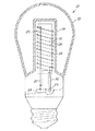
ここでごく詳細な図面を参照すると、図1には無電極蛍光ランプ10が示されている。この無電極蛍光ランプ10は、チャンバ14を含むエンベロープ12を有している。磁性材料のコア16がチャンバ14内部に位置付けられており、該コアを包囲する第1の巻き線18を有する。前記磁性材料は、有利にはフェライトである。この第1の巻き線18は、第1の導入線20および第2の導入線22を有しており、これらの導入線は高周波の電圧供給部またはバラスト24に取り付けられている。第2の巻き線26が該コア16を包囲しており、該第2の巻き線26の各1巻きが、第1の巻き線18の1巻きに隣接して位置付けられ、該第1の巻き線から電気的に絶縁されている。この第2の巻き線26の一方の端部は自由端部28であり、他方の端部30は導入線のうち1つに、たとえば20に接続されている。編組されたスリーブ32(図2には概略的に示されており、図3には図式的に示されている)が他方の導入線22を包囲する。第1の巻き線18は一般的に、RFアンテナと称される。これらの図面では第1の巻き線18は、比較的太い線として示されており、第2の巻き線26は、比較的細い線として示されている。これらの線の太さは例として図解するためだけのものであり、これらのワイヤは実際には同一である。編組されたスリーブ32は、局部グラウンドに結合されている。この低コストの解決手段だけでも、伝導性のEMIレベルを十分に低減して、このような干渉におけるすべての現行の規制に対して、十分な余裕をもって適合することができる。
Referring now to the detailed drawing, FIG. 1 shows an electrodeless
択一的な解決手段が図4および5に示されており、図4は回路の概略図であり、図5はコアおよび巻き線を図式的に示している。ここでは磁性材料のコア16aは、該コア16aを包囲する第1の巻き線18aを有している。この第1の巻き線18aは、第1の導入線および第2の導入線20aおよび22aを有しており、これらの導入線は高周波電源24に取り付けられている。この実施例では、第2の巻き線26aは該コア16aを包囲しており、該第2の巻き線の各1巻きは、第1の巻き線の1巻きに隣接して位置付けられており、該第1の巻き線から電気的に絶縁されている。第2の巻き線は第1の巻き線と同様に2本巻となっており、第1の巻き線および第2の巻き線は等しい長さを有する。ここでも、第2の巻き線26aの一方の端部は、第1の巻き線18aの導入線のうち1つに、たとえば20aに、接続点30aにおいて接続されている。第1の巻き線および第2の巻き線は逆位相を有するので、等しい長さと等しいRF電圧と逆の位相を有するこれら2つのRFワイヤでは、ランプ本体に結合するRFが相殺される。この実施形態において電気的な対称性を維持するためには、逆位相を有する2つの巻き線の長さを、非相補的な部分において相互に等しく保つことが重要である。このことは、フェライトコア16aの中間に2重線路を形成するように両導入線を一緒にすることによって達成される。このことは図5に示されている。
Alternative solutions are shown in FIGS. 4 and 5, where FIG. 4 is a schematic diagram of the circuit, and FIG. 5 schematically shows the core and windings. Here, the
図示された2つの実施形態のうちいずれか1つの形態を具現化することによって、無電極蛍光ランプのEMIレベルを規制まで低減し、規制より下回って低減することができ、ランプ全体を遮蔽するという高価な遮蔽を行うことなく、商業および住宅において適用することができる。このことによって、可視光を放射するための表面積が大きいA字形のランプを使用して、ランプ効率を格段に上昇させることができる。 By embodying any one of the two illustrated embodiments, the EMI level of the electrodeless fluorescent lamp can be reduced to the regulation, can be reduced below the regulation, and the entire lamp is shielded. It can be applied in commerce and residential without expensive shielding. As a result, the lamp efficiency can be significantly increased by using an A-shaped lamp having a large surface area for emitting visible light.
ここでは、本発明の有利な実施形態を参照して開示内容を図示および説明したが、当業者であれば、請求項で定義された本発明の範囲から逸脱することなく、種々の変更および補足を行うことができる。 Although the disclosure has been illustrated and described herein with reference to advantageous embodiments of the invention, various modifications and supplements will occur to those skilled in the art without departing from the scope of the invention as defined in the claims. It can be performed.
Claims (2)
チャンバを含むランプエンベロープと、該チャンバ内部の磁性材料のコアと、該コアを包囲する第1の巻き線と第2の巻き線とを有しており、
前記第1の巻き線は、第1の導入線および第2の導入線を有しており、
前記第1の導入線および第2の導入線は、高周波電源に接続されており、
前記第2の巻き線の各1巻きは、前記第1の巻き線の各1巻きに隣接して位置づけられており、該第1の巻き線と電気的に絶縁されており、
前記第1の巻き線および第2の巻き線は2本巻であり、等しい長さを有しており、
前記第2の巻き線の一方の端部は、前記第1の巻き線の前記導入線のうちの1つに接続されており、
前記コアの中間において、前記第2の巻き線の他方の端部は、前記第1の巻き線の前記導入線のうちの前記1つと共に2重線路を形成している一方、前記第2の巻き線の前記一方の端部は、前記第1の巻き線の前記導入線のうちの他の1つの一部と共に2重線路を形成していることにより、相互に逆位相を有する前記第1の巻き線および第2の巻き線の長さは相互に等しく保たれていることを特徴とする無電極蛍光ランプ。 In electrodeless fluorescent lamps,
A lamp envelope including a chamber; a core of magnetic material inside the chamber; and a first winding and a second winding surrounding the core;
The first winding has a first lead wire and a second lead wire;
The first introduction line and the second introduction line are connected to a high frequency power source,
Each turn of the second winding is positioned adjacent to each turn of the first winding and is electrically insulated from the first winding;
The first winding and the second winding are two windings and have equal lengths;
One end of the second winding is connected to one of the lead wires of the first winding;
In the middle of the core, the other end of the second winding forms a double line with the one of the lead wires of the first winding, while the second winding The one end of the winding forms a double line together with a part of the other one of the lead wires of the first winding, so that the first ends having opposite phases to each other An electrodeless fluorescent lamp characterized in that the length of the winding and the length of the second winding are kept equal to each other.
Applications Claiming Priority (4)
| Application Number | Priority Date | Filing Date | Title |
|---|---|---|---|
| US56308804P | 2004-04-16 | 2004-04-16 | |
| US60/563088 | 2004-04-16 | ||
| US10/872,058 US7180230B2 (en) | 2004-04-16 | 2004-06-18 | RF induction lamp with reduced electromagnetic interference |
| US10/872058 | 2004-06-18 |
Publications (2)
| Publication Number | Publication Date |
|---|---|
| JP2005310781A JP2005310781A (en) | 2005-11-04 |
| JP4944388B2 true JP4944388B2 (en) | 2012-05-30 |
Family
ID=34933717
Family Applications (1)
| Application Number | Title | Priority Date | Filing Date |
|---|---|---|---|
| JP2005120097A Expired - Fee Related JP4944388B2 (en) | 2004-04-16 | 2005-04-18 | RF induction lamp with reduced electromagnetic interference |
Country Status (6)
| Country | Link |
|---|---|
| US (1) | US7180230B2 (en) |
| EP (1) | EP1587134A3 (en) |
| JP (1) | JP4944388B2 (en) |
| KR (1) | KR101132501B1 (en) |
| CN (2) | CN101692418B (en) |
| CA (1) | CA2489652C (en) |
Families Citing this family (33)
| Publication number | Priority date | Publication date | Assignee | Title |
|---|---|---|---|---|
| KR100806852B1 (en) * | 2007-04-17 | 2008-02-22 | 금호전기주식회사 | Electrodeless fluorescent lamp |
| KR100806853B1 (en) * | 2007-04-24 | 2008-02-22 | 금호전기주식회사 | Electrodeless fluorescent lamp |
| KR100850795B1 (en) * | 2007-04-24 | 2008-08-06 | 금호전기주식회사 | Electrodeless fluorescent lamp |
| KR100806857B1 (en) * | 2007-04-25 | 2008-02-22 | 금호전기주식회사 | Electrodeless fluorescent lamp |
| KR100806854B1 (en) * | 2007-04-25 | 2008-02-22 | 금호전기주식회사 | Electrodeless fluorescent lamp |
| KR100806856B1 (en) * | 2007-04-25 | 2008-02-22 | 금호전기주식회사 | Electrodeless fluorescent lamp |
| US8487544B2 (en) | 2010-09-29 | 2013-07-16 | Osram Sylvania Inc. | Power splitter circuit for electrodeless lamp |
| WO2014082039A1 (en) * | 2012-11-26 | 2014-05-30 | Lucidity Lights, Inc. | Induction rf fluorescent lamp |
| US10141179B2 (en) | 2012-11-26 | 2018-11-27 | Lucidity Lights, Inc. | Fast start RF induction lamp with metallic structure |
| US8698413B1 (en) | 2012-11-26 | 2014-04-15 | Lucidity Lights, Inc. | RF induction lamp with reduced electromagnetic interference |
| US9129791B2 (en) | 2012-11-26 | 2015-09-08 | Lucidity Lights, Inc. | RF coupler stabilization in an induction RF fluorescent light bulb |
| US20140145592A1 (en) * | 2012-11-26 | 2014-05-29 | Lucidity Lights, Inc. | Induction rf fluorescent light bulb |
| US9245734B2 (en) | 2012-11-26 | 2016-01-26 | Lucidity Lights, Inc. | Fast start induction RF fluorescent lamp with burst-mode dimming |
| US8872426B2 (en) | 2012-11-26 | 2014-10-28 | Lucidity Lights, Inc. | Arrangements and methods for triac dimming of gas discharge lamps powered by electronic ballasts |
| US20140375203A1 (en) | 2012-11-26 | 2014-12-25 | Lucidity Lights, Inc. | Induction rf fluorescent lamp with helix mount |
| US9524861B2 (en) | 2012-11-26 | 2016-12-20 | Lucidity Lights, Inc. | Fast start RF induction lamp |
| US8941304B2 (en) | 2012-11-26 | 2015-01-27 | Lucidity Lights, Inc. | Fast start dimmable induction RF fluorescent light bulb |
| US9460907B2 (en) * | 2012-11-26 | 2016-10-04 | Lucidity Lights, Inc. | Induction RF fluorescent lamp with load control for external dimming device |
| US10529551B2 (en) | 2012-11-26 | 2020-01-07 | Lucidity Lights, Inc. | Fast start fluorescent light bulb |
| US10128101B2 (en) * | 2012-11-26 | 2018-11-13 | Lucidity Lights, Inc. | Dimmable induction RF fluorescent lamp with reduced electromagnetic interference |
| US9129792B2 (en) | 2012-11-26 | 2015-09-08 | Lucidity Lights, Inc. | Fast start induction RF fluorescent lamp with reduced electromagnetic interference |
| US8975829B2 (en) | 2013-04-25 | 2015-03-10 | Lucidity Lights, Inc. | RF induction lamp with isolation system for air-core power coupler |
| US8901842B2 (en) * | 2013-04-25 | 2014-12-02 | Lucidity Lights, Inc. | RF induction lamp with ferrite isolation system |
| US9161422B2 (en) | 2012-11-26 | 2015-10-13 | Lucidity Lights, Inc. | Electronic ballast having improved power factor and total harmonic distortion |
| US9209008B2 (en) | 2012-11-26 | 2015-12-08 | Lucidity Lights, Inc. | Fast start induction RF fluorescent light bulb |
| US9305765B2 (en) | 2012-11-26 | 2016-04-05 | Lucidity Lights, Inc. | High frequency induction lighting |
| USD745982S1 (en) | 2013-07-19 | 2015-12-22 | Lucidity Lights, Inc. | Inductive lamp |
| USD746490S1 (en) | 2013-07-19 | 2015-12-29 | Lucidity Lights, Inc. | Inductive lamp |
| USD745981S1 (en) | 2013-07-19 | 2015-12-22 | Lucidity Lights, Inc. | Inductive lamp |
| USD747507S1 (en) | 2013-08-02 | 2016-01-12 | Lucidity Lights, Inc. | Inductive lamp |
| USD747009S1 (en) | 2013-08-02 | 2016-01-05 | Lucidity Lights, Inc. | Inductive lamp |
| USD854198S1 (en) | 2017-12-28 | 2019-07-16 | Lucidity Lights, Inc. | Inductive lamp |
| US10236174B1 (en) | 2017-12-28 | 2019-03-19 | Lucidity Lights, Inc. | Lumen maintenance in fluorescent lamps |
Family Cites Families (19)
| Publication number | Priority date | Publication date | Assignee | Title |
|---|---|---|---|---|
| US4187447A (en) * | 1978-09-11 | 1980-02-05 | General Electric Company | Electrodeless fluorescent lamp with reduced spurious electromagnetic radiation |
| US4344214A (en) * | 1980-07-31 | 1982-08-17 | Raychem Corporation | Internal pipe line delivery device |
| FR2503463B1 (en) * | 1981-04-03 | 1985-07-12 | Lacroix Jacques | CONNECTION DEVICE |
| NL8401307A (en) | 1984-04-24 | 1985-11-18 | Philips Nv | ELECTRESSLESS LOW PRESSURE DISCHARGE LAMP. |
| CN1003829B (en) * | 1985-04-01 | 1989-04-05 | 菲利浦光灯制造公司 | Electrodeless low voltage discharge lamp |
| NL8800584A (en) * | 1988-03-09 | 1989-10-02 | Philips Nv | ELECTRESSLESS LOW PRESSURE DISCHARGE LAMP. |
| HU205490B (en) * | 1990-04-06 | 1992-04-28 | Philips Nv | Electrodeless low-pressure discharge lamp |
| EP0594247B1 (en) * | 1992-10-21 | 1997-09-24 | Koninklijke Philips Electronics N.V. | Illumination unit and electrodeless low-pressure discharge lamp suitable for use therein |
| EP0594245B1 (en) * | 1992-10-21 | 1997-09-17 | Koninklijke Philips Electronics N.V. | Illumination unit and electrodeless low-pressure discharge lamp suitable for use therein |
| JPH06223789A (en) * | 1992-12-23 | 1994-08-12 | Philips Electron Nv | Electrodeless low pressure discharge lamp |
| US6057649A (en) * | 1993-05-11 | 2000-05-02 | U.S. Philips Corporation | Illumination unit, electrodeless low-pressure discharge lamp, and coil suitable for use therein |
| BE1007878A3 (en) * | 1993-12-17 | 1995-11-07 | Philips Electronics Nv | LIGHTING UNIT, AND electrodeless low-pressure discharge lamp HOLDER AND POWER DEVICE DESIGNED FOR USE IN LIGHTING UNIT. |
| EP0753203B1 (en) * | 1994-12-23 | 1998-11-18 | Koninklijke Philips Electronics N.V. | Electrodeless low-pressure discharge lamp, and lighting unit provided with such a lamp |
| CN1161565A (en) * | 1995-06-14 | 1997-10-08 | 奥斯兰姆施尔凡尼亚公司 | Discharge light source with reduced magnetic interference |
| WO1997040519A1 (en) * | 1996-04-19 | 1997-10-30 | Philips Electronics N.V. | Electrodeless low-pressure discharge lamp |
| US5726523A (en) * | 1996-05-06 | 1998-03-10 | Matsushita Electric Works Research & Development Labratory | Electrodeless fluorescent lamp with bifilar coil and faraday shield |
| US5866991A (en) * | 1996-07-17 | 1999-02-02 | General Electric Company | Induction lamp with oppositely oriented coil winding layers |
| JP3613022B2 (en) * | 1998-08-24 | 2005-01-26 | 松下電工株式会社 | Electrodeless discharge lamp device |
| WO2003065676A1 (en) | 2002-01-28 | 2003-08-07 | Philip Morris Products S.A. | Method and authentication server for controlling access to a resource accessible through a communications network |
-
2004
- 2004-06-18 US US10/872,058 patent/US7180230B2/en not_active Expired - Fee Related
- 2004-12-07 CA CA2489652A patent/CA2489652C/en not_active Expired - Fee Related
-
2005
- 2005-02-11 EP EP05002967A patent/EP1587134A3/en not_active Withdrawn
- 2005-04-13 KR KR1020050030688A patent/KR101132501B1/en not_active IP Right Cessation
- 2005-04-15 CN CN2009101793438A patent/CN101692418B/en not_active Expired - Fee Related
- 2005-04-15 CN CN2005100674202A patent/CN1700407B/en not_active Expired - Fee Related
- 2005-04-18 JP JP2005120097A patent/JP4944388B2/en not_active Expired - Fee Related
Also Published As
| Publication number | Publication date |
|---|---|
| CN1700407A (en) | 2005-11-23 |
| CN101692418A (en) | 2010-04-07 |
| US7180230B2 (en) | 2007-02-20 |
| JP2005310781A (en) | 2005-11-04 |
| KR20060045656A (en) | 2006-05-17 |
| CN101692418B (en) | 2011-10-19 |
| EP1587134A2 (en) | 2005-10-19 |
| CN1700407B (en) | 2010-05-12 |
| CA2489652A1 (en) | 2005-10-16 |
| EP1587134A3 (en) | 2010-01-06 |
| US20050280344A1 (en) | 2005-12-22 |
| KR101132501B1 (en) | 2012-04-24 |
| CA2489652C (en) | 2013-02-12 |
Similar Documents
| Publication | Publication Date | Title |
|---|---|---|
| JP4944388B2 (en) | RF induction lamp with reduced electromagnetic interference | |
| US5886472A (en) | Electrodeless lamp having compensation loop for suppression of magnetic interference | |
| CA2108434C (en) | Capacitively coupled rf fluorescent lamp with rf magnetic enhancement | |
| US6768248B2 (en) | Electrodeless lamp | |
| JPH0782832B2 (en) | Electrodeless fluorescent lamp | |
| US20030222557A1 (en) | Electrodeless discharge lamp | |
| CA1144981A (en) | Electrodeless gas discharge lamp | |
| US4187447A (en) | Electrodeless fluorescent lamp with reduced spurious electromagnetic radiation | |
| JPS59940B2 (en) | fluorescent light | |
| JP2003132809A (en) | Magnetron | |
| US6297583B1 (en) | Gas discharge lamp assembly with improved r.f. shielding | |
| JP3613022B2 (en) | Electrodeless discharge lamp device | |
| JP3440676B2 (en) | Electrodeless low pressure discharge lamp | |
| JP4479562B2 (en) | Electrodeless discharge lamp lighting device and lighting fixture | |
| JP4232598B2 (en) | Electrodeless discharge lamp lighting device and lighting device | |
| JP2003317672A (en) | Electrodeless discharge lamp | |
| JP4696962B2 (en) | Electrodeless discharge lamp device and lighting fixture | |
| KR101827279B1 (en) | Apparatus for improving power efficiency | |
| JP3890758B2 (en) | Electrodeless discharge lamp lighting device | |
| JP4058304B2 (en) | Electrodeless discharge lamp | |
| KR101410324B1 (en) | Electrodeless lamp | |
| JP3906517B2 (en) | Electrodeless discharge lamp lighting device | |
| CN102840475A (en) | Separable bulb type electrodeless lamp | |
| JPH10162791A (en) | Electrodeless discharge lamp, electrodeless discharge lamp lighting device, lighting system, and liquid treatment system | |
| JP2008186608A (en) | Electrodeless discharge lamp device and lighting fixture |
Legal Events
| Date | Code | Title | Description |
|---|---|---|---|
| A621 | Written request for application examination |
Free format text: JAPANESE INTERMEDIATE CODE: A621 Effective date: 20080208 |
|
| RD04 | Notification of resignation of power of attorney |
Free format text: JAPANESE INTERMEDIATE CODE: A7424 Effective date: 20101228 |
|
| A977 | Report on retrieval |
Free format text: JAPANESE INTERMEDIATE CODE: A971007 Effective date: 20110131 |
|
| A131 | Notification of reasons for refusal |
Free format text: JAPANESE INTERMEDIATE CODE: A131 Effective date: 20110204 |
|
| A601 | Written request for extension of time |
Free format text: JAPANESE INTERMEDIATE CODE: A601 Effective date: 20110428 |
|
| A602 | Written permission of extension of time |
Free format text: JAPANESE INTERMEDIATE CODE: A602 Effective date: 20110509 |
|
| A601 | Written request for extension of time |
Free format text: JAPANESE INTERMEDIATE CODE: A601 Effective date: 20110606 |
|
| A602 | Written permission of extension of time |
Free format text: JAPANESE INTERMEDIATE CODE: A602 Effective date: 20110609 |
|
| A601 | Written request for extension of time |
Free format text: JAPANESE INTERMEDIATE CODE: A601 Effective date: 20110704 |
|
| A602 | Written permission of extension of time |
Free format text: JAPANESE INTERMEDIATE CODE: A602 Effective date: 20110707 |
|
| A521 | Written amendment |
Free format text: JAPANESE INTERMEDIATE CODE: A523 Effective date: 20110804 |
|
| A131 | Notification of reasons for refusal |
Free format text: JAPANESE INTERMEDIATE CODE: A131 Effective date: 20110824 |
|
| A601 | Written request for extension of time |
Free format text: JAPANESE INTERMEDIATE CODE: A601 Effective date: 20111122 |
|
| A602 | Written permission of extension of time |
Free format text: JAPANESE INTERMEDIATE CODE: A602 Effective date: 20111128 |
|
| A601 | Written request for extension of time |
Free format text: JAPANESE INTERMEDIATE CODE: A601 Effective date: 20111221 |
|
| A602 | Written permission of extension of time |
Free format text: JAPANESE INTERMEDIATE CODE: A602 Effective date: 20111227 |
|
| A521 | Written amendment |
Free format text: JAPANESE INTERMEDIATE CODE: A523 Effective date: 20120123 |
|
| TRDD | Decision of grant or rejection written | ||
| A01 | Written decision to grant a patent or to grant a registration (utility model) |
Free format text: JAPANESE INTERMEDIATE CODE: A01 Effective date: 20120210 |
|
| A01 | Written decision to grant a patent or to grant a registration (utility model) |
Free format text: JAPANESE INTERMEDIATE CODE: A01 |
|
| A61 | First payment of annual fees (during grant procedure) |
Free format text: JAPANESE INTERMEDIATE CODE: A61 Effective date: 20120302 |
|
| R150 | Certificate of patent or registration of utility model |
Free format text: JAPANESE INTERMEDIATE CODE: R150 |
|
| FPAY | Renewal fee payment (event date is renewal date of database) |
Free format text: PAYMENT UNTIL: 20150309 Year of fee payment: 3 |
|
| LAPS | Cancellation because of no payment of annual fees |