EP1587134A2 - RF Induction lamp with reduced electromagnetic interference - Google Patents
RF Induction lamp with reduced electromagnetic interference Download PDFInfo
- Publication number
- EP1587134A2 EP1587134A2 EP05002967A EP05002967A EP1587134A2 EP 1587134 A2 EP1587134 A2 EP 1587134A2 EP 05002967 A EP05002967 A EP 05002967A EP 05002967 A EP05002967 A EP 05002967A EP 1587134 A2 EP1587134 A2 EP 1587134A2
- Authority
- EP
- European Patent Office
- Prior art keywords
- winding
- core
- lead
- wires
- chamber
- Prior art date
- Legal status (The legal status is an assumption and is not a legal conclusion. Google has not performed a legal analysis and makes no representation as to the accuracy of the status listed.)
- Withdrawn
Links
- 230000006698 induction Effects 0.000 title 1
- 238000004804 winding Methods 0.000 claims abstract description 64
- 239000000696 magnetic material Substances 0.000 claims abstract description 9
- 229910000859 α-Fe Inorganic materials 0.000 claims abstract description 6
- 238000000576 coating method Methods 0.000 description 3
- 238000012216 screening Methods 0.000 description 3
- 239000011248 coating agent Substances 0.000 description 2
- 230000008878 coupling Effects 0.000 description 2
- 238000010168 coupling process Methods 0.000 description 2
- 238000005859 coupling reaction Methods 0.000 description 2
- 238000010586 diagram Methods 0.000 description 2
- 238000010276 construction Methods 0.000 description 1
- 239000002184 metal Substances 0.000 description 1
- 238000012986 modification Methods 0.000 description 1
- 230000004048 modification Effects 0.000 description 1
Images

Classifications
-
- H—ELECTRICITY
- H01—ELECTRIC ELEMENTS
- H01J—ELECTRIC DISCHARGE TUBES OR DISCHARGE LAMPS
- H01J65/00—Lamps without any electrode inside the vessel; Lamps with at least one main electrode outside the vessel
- H01J65/04—Lamps in which a gas filling is excited to luminesce by an external electromagnetic field or by external corpuscular radiation, e.g. for indicating plasma display panels
- H01J65/042—Lamps in which a gas filling is excited to luminesce by an external electromagnetic field or by external corpuscular radiation, e.g. for indicating plasma display panels by an external electromagnetic field
- H01J65/048—Lamps in which a gas filling is excited to luminesce by an external electromagnetic field or by external corpuscular radiation, e.g. for indicating plasma display panels by an external electromagnetic field the field being produced by using an excitation coil
Definitions
- This invention relates to electrodeless fluorescent lamps and more particularly to such lamps having reduced electromagnetic interference (EMI) making them more suitable for the commercial and residential markets.
- EMI electromagnetic interference
- Electrodeless fluorescent lamps generally require mounting in a special fixture designed to shield the surrounding area from the EMI generated by the operation of the lamp.
- Such fixtures function as a Faraday shield and allow the lamp to operate without too much disturbance to adjacent devices; however, such special fixtures also limit the places where the lamps can be employed.
- Yet another object of the invention is the provision of a lamp design providing EMI-free electrodeless fluorescent lamps without employing the complicated screening means of the prior art lamps.
- an electrodeless fluorescent lamp having a lamp envelope that includes a chamber with core of magnetic material therein.
- a first winding surrounds the core and has a first hot lead-in wire attached to a high frequency end of the voltage supply and a second lead-in connected to the local ground of the RF voltage supply.
- a second winding surrounds the core, and respective turns of the second winding are located adjacent turns of the first winding and electrically insulated therefrom.
- the second winding has a free end and has another end connected to one of the grounded lead-in wires of the first winding.
- a grounded braided sheath surrounds the hot lead-in wire of the first winding.
- the first winding and the second winding are bifilar and have equal lengths. This construction improves the electrostatic symmetry of the lamp by screening the lead-in wire of the driven winding.
- an electrodeless fluorescent lamp having a lamp envelope that includes a chamber with a core of magnetic material therein.
- a first winding surrounds the core and has first and second lead-ins attached to a high frequency supply.
- a second winding surrounds the core with respective turns of the second winding located adjacent turns of the first winding and electrically insulated therefrom.
- the first winding and the second winding are bifilar and have equal lengths.
- One end of the second winding is connected to one of the lead-ins of the first winding.
- the two radio frequency windings that is, the first and second windings
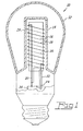
- FIG. 1 an electrodeless fluorescent lamp 10 having an envelope 12 that includes a chamber 14.
- a core 16 of magnetic material preferably ferrite, is positioned in the chamber 14 and has a first winding 18 surrounding the core and having first and second lead-in wires 20, 22, attached to a high frequency voltage supply or ballast 24.
- a second winding 26 surrounds the core 16, respective turns of the second winding 26 being located adjacent turns of the first winding 18 and electrically insulated therefrom.
- the second winding 26 has a free end 28 and has another end 30 connected to one of the lead-in wires, for example 20.
- a braided sheath 32 (shown schematically in Fig.
- the first winding 18 is generally called the RF antenna.
- the first winding 18 is shown as a relatively thick line and the second winding 26 is shown as a relatively thin line, the line widths being exemplary and for illustrative purposes only, the actual wires being identical.
- the braided sheath 32 is connected to the local ground. This inexpensive solution alone reduces the conductive EMI level sufficiently to pass all existing regulations on such interference with significant reserve.
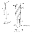
- FIG. 4 An alternate solution is shown in Figs. 4 and 5, with Fig. 4 showing the circuit schematically and Fig. 5 showing the core and windings diagrammatically, wherein the core 16a of magnetic material has a first winding 18a surrounding the core 16a and having first and second lead-ins wires 20a and 22a attached to a high frequency supply 24.
- the second winding 26a surrounding the core 16a respective turns of the second winding being located adjacent turns of the first winding and electrically insulated therefrom, is bifilar, as is the first winding and the first winding and the second winding have equal lengths.
- one end of the second winding 30a is connected to one of the lead-ins, for example, 20a, of the first winding 18a.
- the first and second windings have opposite phase; thus, the two RF wires with equal length and equal RF voltage and opposite phase have a mutually canceled RF coupling to the lamp body.
Landscapes
- Physics & Mathematics (AREA)
- Engineering & Computer Science (AREA)
- Plasma & Fusion (AREA)
- Electromagnetism (AREA)
- Discharge Lamps And Accessories Thereof (AREA)
- Circuit Arrangements For Discharge Lamps (AREA)
- Non-Portable Lighting Devices Or Systems Thereof (AREA)
Abstract
Description
- This application claims priority from Provisional Patent Application No. 60/563,088, filed April 16, 2004.
- This invention relates to electrodeless fluorescent lamps and more particularly to such lamps having reduced electromagnetic interference (EMI) making them more suitable for the commercial and residential markets.
- Electrodeless fluorescent lamps generally require mounting in a special fixture designed to shield the surrounding area from the EMI generated by the operation of the lamp. Such fixtures function as a Faraday shield and allow the lamp to operate without too much disturbance to adjacent devices; however, such special fixtures also limit the places where the lamps can be employed.
- Several current lamps attempt to solve this problem by various means, one of which involves applying EMI screening to the lamp envelope in the form of a transparent conductive coating on the interior surface of the lens portion of the lamp together with an opaque metal coating on the outside surfaces of the sides of the lamp envelope. The coatings are connected electrically to the local ground of the lamp. This system greatly increases the cost of the lamp and reduces the lamps efficiency and is really only suitable for PAR lamps.
- Another approach, shown in U.S. Patent No. 4,710,678, involves the use of a second winding interspersed between the primary windings on the ferrite core of the lamp. The second winding has one free end and the other end connected to one end of the primary winding. Interference currents at the supply mains with this approach are alleged to be strongly suppressed.
- It would be an advance in the art if the EMI of electrodeless fluorescent lamps could be further improved at reasonable cost to allow more usage in residential and commercial applications.
- It is, therefore, an object of the invention to obviate the disadvantages of the prior art.
- It is another object of the invention to enhance electrodeless fluorescent lamps.
- It is still another object of the invention to enhance the efficiency of electrodeless fluorescent lamps.
- Yet another object of the invention is the provision of a lamp design providing EMI-free electrodeless fluorescent lamps without employing the complicated screening means of the prior art lamps.
- These objects are accomplished, in one aspect of the invention, by an electrodeless fluorescent lamp having a lamp envelope that includes a chamber with core of magnetic material therein. A first winding surrounds the core and has a first hot lead-in wire attached to a high frequency end of the voltage supply and a second lead-in connected to the local ground of the RF voltage supply. A second winding surrounds the core, and respective turns of the second winding are located adjacent turns of the first winding and electrically insulated therefrom. The second winding has a free end and has another end connected to one of the grounded lead-in wires of the first winding. A grounded braided sheath surrounds the hot lead-in wire of the first winding. The first winding and the second winding are bifilar and have equal lengths. This construction improves the electrostatic symmetry of the lamp by screening the lead-in wire of the driven winding.
- Alternatively, the objects are accomplished, in another aspect of the invention, by an electrodeless fluorescent lamp having a lamp envelope that includes a chamber with a core of magnetic material therein. A first winding surrounds the core and has first and second lead-ins attached to a high frequency supply. A second winding surrounds the core with respective turns of the second winding located adjacent turns of the first winding and electrically insulated therefrom. The first winding and the second winding are bifilar and have equal lengths. One end of the second winding is connected to one of the lead-ins of the first winding. In this embodiment the two radio frequency windings (that is, the first and second windings) have equal lengths and equal radio frequency (RF) voltage but of opposite phase, thereby mutually canceling the RF coupling to the lamp body.
-
- Fig. 1 is a diagrammatic sectional view of an embodiment of the invention;
- Fig. 2 is a circuit diagram of the winding connection;
- Fig. 3 is an enlarged view of the embodiment of Fig. 1;
- Fig. 4 is a circuit diagram of the winding connection in an alternate embodiment; and
- Fig. 5 is a view of an alternate embodiment of the invention.
-
- For a better understanding of the present invention, together with other and further objects, advantages and capabilities thereof, reference is made to the following disclosure and appended claims taken in conjunction with the above-described drawings.
- Referring now to the drawings with greater particularity, there is shown in Fig. 1 an electrodeless
fluorescent lamp 10 having anenvelope 12 that includes achamber 14. Acore 16 of magnetic material, preferably ferrite, is positioned in thechamber 14 and has a first winding 18 surrounding the core and having first and second lead-inwires ballast 24. Asecond winding 26 surrounds thecore 16, respective turns of the second winding 26 being located adjacent turns of the first winding 18 and electrically insulated therefrom. The second winding 26 has afree end 28 and has anotherend 30 connected to one of the lead-in wires, for example 20. A braided sheath 32 (shown schematically in Fig. 2 and diagrammatically in Fig.3) surrounds the other of the lead-inwires 22. The first winding 18 is generally called the RF antenna. In the drawings thefirst winding 18 is shown as a relatively thick line and thesecond winding 26 is shown as a relatively thin line, the line widths being exemplary and for illustrative purposes only, the actual wires being identical. Thebraided sheath 32 is connected to the local ground. This inexpensive solution alone reduces the conductive EMI level sufficiently to pass all existing regulations on such interference with significant reserve. - An alternate solution is shown in Figs. 4 and 5, with Fig. 4 showing the circuit schematically and Fig. 5 showing the core and windings diagrammatically, wherein the
core 16a of magnetic material has a first winding 18a surrounding thecore 16a and having first and second lead-ins wires high frequency supply 24. In this instance the second winding 26a surrounding thecore 16a, respective turns of the second winding being located adjacent turns of the first winding and electrically insulated therefrom, is bifilar, as is the first winding and the first winding and the second winding have equal lengths. Again, one end of the second winding 30a is connected to one of the lead-ins, for example, 20a, of the first winding 18a. The first and second windings have opposite phase; thus, the two RF wires with equal length and equal RF voltage and opposite phase have a mutually canceled RF coupling to the lamp body. To preserve the electric symmetry in this embodiment it is essential to keep the lengths of the two lead-ins having opposite phase equal to each other in their uncompensated parts. This is achieved by putting both leads together to form a double line in the middle of theferrite core 16a, as is shown in Fig. 5. - Implementing either form of the two embodiments shown allows reduction of the EMI level in electrodeless fluorescent lamps up to and lower than regulations permit for commercial and residential applications without expensive shielding of the entire lamp. This allows the use of A-shape lamps with large surface areas to radiate visible light and results in a significant increase in lamp efficacy.
- While there have been shown and described what are present considered to be the preferred embodiments of the invention, it will be apparent to those skilled in the art that various changes and modifications can be made herein without departing from the scope of the invention as defined by the appended claims.
Claims (4)
- An electrodeless fluorescent lamp wherein the improvement comprises:a lamp envelope including a chamber;a core of magnetic material in said chamber;a first winding surrounding said core and having first and second lead-in wires attached to a high frequency voltage supply; anda second winding surrounding said core, respective turns of said second winding being located adjacent turns of said first winding and electrically insulated therefrom, said second winding having a free end and having another end connected to one of said lead-in wires, the other of said lead-in wires being surrounded by a grounded braided sheath.
- An electrodeless fluorescent lamp wherein the improvement comprises:a lamp envelope including a chamber;a core of magnetic material in said chamber;a first winding surrounding said core having first and second lead-ins attached to a high frequency supply; anda second winding surrounding said core, respective turns of said second winding being located adjacent turns of said first winding and electrically insulated therefrom, said first winding and said second winding being bifilar and having equal lengths, one end of said second winding being connected to one of said lead-ins of said first winding..
- The electrodeless fluorescent lamp of Claim 1 wherein said core of magnetic material is a ferrite.
- The electrodeless fluorescent lamp of Claim 2 wherein said core of magnetic material is a ferrite.
Applications Claiming Priority (4)
| Application Number | Priority Date | Filing Date | Title |
|---|---|---|---|
| US872058 | 1986-06-06 | ||
| US56308804P | 2004-04-16 | 2004-04-16 | |
| US563088P | 2004-04-16 | ||
| US10/872,058 US7180230B2 (en) | 2004-04-16 | 2004-06-18 | RF induction lamp with reduced electromagnetic interference |
Publications (2)
| Publication Number | Publication Date |
|---|---|
| EP1587134A2 true EP1587134A2 (en) | 2005-10-19 |
| EP1587134A3 EP1587134A3 (en) | 2010-01-06 |
Family
ID=34933717
Family Applications (1)
| Application Number | Title | Priority Date | Filing Date |
|---|---|---|---|
| EP05002967A Withdrawn EP1587134A3 (en) | 2004-04-16 | 2005-02-11 | RF Induction lamp with reduced electromagnetic interference |
Country Status (6)
| Country | Link |
|---|---|
| US (1) | US7180230B2 (en) |
| EP (1) | EP1587134A3 (en) |
| JP (1) | JP4944388B2 (en) |
| KR (1) | KR101132501B1 (en) |
| CN (2) | CN1700407B (en) |
| CA (1) | CA2489652C (en) |
Cited By (3)
| Publication number | Priority date | Publication date | Assignee | Title |
|---|---|---|---|---|
| CN107889333A (en) * | 2012-11-26 | 2018-04-06 | 明灯有限公司 | Induced RF fluorescent lamp |
| US10418233B2 (en) | 2017-12-28 | 2019-09-17 | Lucidity Lights, Inc. | Burst-mode for low power operation of RF fluorescent lamps |
| US10529551B2 (en) | 2012-11-26 | 2020-01-07 | Lucidity Lights, Inc. | Fast start fluorescent light bulb |
Families Citing this family (30)
| Publication number | Priority date | Publication date | Assignee | Title |
|---|---|---|---|---|
| KR100806852B1 (en) * | 2007-04-17 | 2008-02-22 | 금호전기주식회사 | Induction Fluorescent Lamp |
| KR100806853B1 (en) * | 2007-04-24 | 2008-02-22 | 금호전기주식회사 | Induction Fluorescent Lamp |
| KR100850795B1 (en) * | 2007-04-24 | 2008-08-06 | 금호전기주식회사 | Induction Fluorescent Lamp |
| KR100806857B1 (en) * | 2007-04-25 | 2008-02-22 | 금호전기주식회사 | Electrodeless fluorescent lamp |
| KR100806854B1 (en) * | 2007-04-25 | 2008-02-22 | 금호전기주식회사 | Induction Fluorescent Lamp |
| KR100806856B1 (en) * | 2007-04-25 | 2008-02-22 | 금호전기주식회사 | Induction Fluorescent Lamp |
| US8487544B2 (en) | 2010-09-29 | 2013-07-16 | Osram Sylvania Inc. | Power splitter circuit for electrodeless lamp |
| US9305765B2 (en) | 2012-11-26 | 2016-04-05 | Lucidity Lights, Inc. | High frequency induction lighting |
| US8901842B2 (en) | 2013-04-25 | 2014-12-02 | Lucidity Lights, Inc. | RF induction lamp with ferrite isolation system |
| US10128101B2 (en) * | 2012-11-26 | 2018-11-13 | Lucidity Lights, Inc. | Dimmable induction RF fluorescent lamp with reduced electromagnetic interference |
| US20140145592A1 (en) * | 2012-11-26 | 2014-05-29 | Lucidity Lights, Inc. | Induction rf fluorescent light bulb |
| US20140375203A1 (en) | 2012-11-26 | 2014-12-25 | Lucidity Lights, Inc. | Induction rf fluorescent lamp with helix mount |
| US9161422B2 (en) | 2012-11-26 | 2015-10-13 | Lucidity Lights, Inc. | Electronic ballast having improved power factor and total harmonic distortion |
| US8872426B2 (en) | 2012-11-26 | 2014-10-28 | Lucidity Lights, Inc. | Arrangements and methods for triac dimming of gas discharge lamps powered by electronic ballasts |
| US9460907B2 (en) | 2012-11-26 | 2016-10-04 | Lucidity Lights, Inc. | Induction RF fluorescent lamp with load control for external dimming device |
| US9245734B2 (en) | 2012-11-26 | 2016-01-26 | Lucidity Lights, Inc. | Fast start induction RF fluorescent lamp with burst-mode dimming |
| US8941304B2 (en) | 2012-11-26 | 2015-01-27 | Lucidity Lights, Inc. | Fast start dimmable induction RF fluorescent light bulb |
| US9524861B2 (en) | 2012-11-26 | 2016-12-20 | Lucidity Lights, Inc. | Fast start RF induction lamp |
| US8975829B2 (en) | 2013-04-25 | 2015-03-10 | Lucidity Lights, Inc. | RF induction lamp with isolation system for air-core power coupler |
| US9209008B2 (en) | 2012-11-26 | 2015-12-08 | Lucidity Lights, Inc. | Fast start induction RF fluorescent light bulb |
| US10141179B2 (en) | 2012-11-26 | 2018-11-27 | Lucidity Lights, Inc. | Fast start RF induction lamp with metallic structure |
| US9129792B2 (en) | 2012-11-26 | 2015-09-08 | Lucidity Lights, Inc. | Fast start induction RF fluorescent lamp with reduced electromagnetic interference |
| US8698413B1 (en) | 2012-11-26 | 2014-04-15 | Lucidity Lights, Inc. | RF induction lamp with reduced electromagnetic interference |
| US9129791B2 (en) | 2012-11-26 | 2015-09-08 | Lucidity Lights, Inc. | RF coupler stabilization in an induction RF fluorescent light bulb |
| USD746490S1 (en) | 2013-07-19 | 2015-12-29 | Lucidity Lights, Inc. | Inductive lamp |
| USD745982S1 (en) | 2013-07-19 | 2015-12-22 | Lucidity Lights, Inc. | Inductive lamp |
| USD745981S1 (en) | 2013-07-19 | 2015-12-22 | Lucidity Lights, Inc. | Inductive lamp |
| USD747009S1 (en) | 2013-08-02 | 2016-01-05 | Lucidity Lights, Inc. | Inductive lamp |
| USD747507S1 (en) | 2013-08-02 | 2016-01-12 | Lucidity Lights, Inc. | Inductive lamp |
| USD854198S1 (en) | 2017-12-28 | 2019-07-16 | Lucidity Lights, Inc. | Inductive lamp |
Citations (1)
| Publication number | Priority date | Publication date | Assignee | Title |
|---|---|---|---|---|
| WO2003065676A1 (en) | 2002-01-28 | 2003-08-07 | Philip Morris Products S.A. | Method and authentication server for controlling access to a resource accessible through a communications network |
Family Cites Families (18)
| Publication number | Priority date | Publication date | Assignee | Title |
|---|---|---|---|---|
| US4187447A (en) * | 1978-09-11 | 1980-02-05 | General Electric Company | Electrodeless fluorescent lamp with reduced spurious electromagnetic radiation |
| US4344214A (en) * | 1980-07-31 | 1982-08-17 | Raychem Corporation | Internal pipe line delivery device |
| FR2503463B1 (en) * | 1981-04-03 | 1985-07-12 | Lacroix Jacques | CONNECTION DEVICE |
| NL8401307A (en) | 1984-04-24 | 1985-11-18 | Philips Nv | ELECTRESSLESS LOW PRESSURE DISCHARGE LAMP. |
| CN1003829B (en) * | 1985-04-01 | 1989-04-05 | 菲利浦光灯制造公司 | Electrodeless Low Pressure Discharge Lamps |
| NL8800584A (en) * | 1988-03-09 | 1989-10-02 | Philips Nv | ELECTRESSLESS LOW PRESSURE DISCHARGE LAMP. |
| ES2075324T3 (en) * | 1990-04-06 | 1995-10-01 | Philips Electronics Nv | LOW PRESSURE DISCHARGE LAMP WITHOUT ELECTRODES. |
| ES2110052T3 (en) * | 1992-10-21 | 1998-02-01 | Koninkl Philips Electronics Nv | LIGHTING EQUIPMENT AND LOW PRESSURE LAMP WITHOUT ELECTRODES SUITABLE FOR USE IN THIS LIGHTING EQUIPMENT. |
| EP0594245B1 (en) * | 1992-10-21 | 1997-09-17 | Koninklijke Philips Electronics N.V. | Illumination unit and electrodeless low-pressure discharge lamp suitable for use therein |
| JPH06223789A (en) * | 1992-12-23 | 1994-08-12 | Philips Electron Nv | Electrodeless low pressure discharge lamp |
| US6057649A (en) * | 1993-05-11 | 2000-05-02 | U.S. Philips Corporation | Illumination unit, electrodeless low-pressure discharge lamp, and coil suitable for use therein |
| BE1007878A3 (en) * | 1993-12-17 | 1995-11-07 | Philips Electronics Nv | LIGHTING UNIT, AND electrodeless low-pressure discharge lamp HOLDER AND POWER DEVICE DESIGNED FOR USE IN LIGHTING UNIT. |
| DE69506093T2 (en) * | 1994-12-23 | 1999-06-10 | Koninklijke Philips Electronics N.V., Eindhoven | ELECTRODELESS LOW PRESSURE DISCHARGE LAMP AND LIGHTING UNIT WITH SUCH A LAMP |
| CN1161565A (en) * | 1995-06-14 | 1997-10-08 | 奥斯兰姆施尔凡尼亚公司 | Discharge light source with reduced magnetic interference |
| KR19990028248A (en) * | 1996-04-19 | 1999-04-15 | 엠. 제이. 엠. 반캄 | Induction Low Voltage Discharge Lamp |
| US5726523A (en) * | 1996-05-06 | 1998-03-10 | Matsushita Electric Works Research & Development Labratory | Electrodeless fluorescent lamp with bifilar coil and faraday shield |
| US5866991A (en) * | 1996-07-17 | 1999-02-02 | General Electric Company | Induction lamp with oppositely oriented coil winding layers |
| JP3613022B2 (en) * | 1998-08-24 | 2005-01-26 | 松下電工株式会社 | Electrodeless discharge lamp device |
-
2004
- 2004-06-18 US US10/872,058 patent/US7180230B2/en not_active Expired - Fee Related
- 2004-12-07 CA CA2489652A patent/CA2489652C/en not_active Expired - Fee Related
-
2005
- 2005-02-11 EP EP05002967A patent/EP1587134A3/en not_active Withdrawn
- 2005-04-13 KR KR1020050030688A patent/KR101132501B1/en not_active Expired - Fee Related
- 2005-04-15 CN CN2005100674202A patent/CN1700407B/en not_active Expired - Fee Related
- 2005-04-15 CN CN2009101793438A patent/CN101692418B/en not_active Expired - Fee Related
- 2005-04-18 JP JP2005120097A patent/JP4944388B2/en not_active Expired - Fee Related
Patent Citations (1)
| Publication number | Priority date | Publication date | Assignee | Title |
|---|---|---|---|---|
| WO2003065676A1 (en) | 2002-01-28 | 2003-08-07 | Philip Morris Products S.A. | Method and authentication server for controlling access to a resource accessible through a communications network |
Cited By (3)
| Publication number | Priority date | Publication date | Assignee | Title |
|---|---|---|---|---|
| CN107889333A (en) * | 2012-11-26 | 2018-04-06 | 明灯有限公司 | Induced RF fluorescent lamp |
| US10529551B2 (en) | 2012-11-26 | 2020-01-07 | Lucidity Lights, Inc. | Fast start fluorescent light bulb |
| US10418233B2 (en) | 2017-12-28 | 2019-09-17 | Lucidity Lights, Inc. | Burst-mode for low power operation of RF fluorescent lamps |
Also Published As
| Publication number | Publication date |
|---|---|
| CN101692418B (en) | 2011-10-19 |
| KR101132501B1 (en) | 2012-04-24 |
| KR20060045656A (en) | 2006-05-17 |
| CA2489652A1 (en) | 2005-10-16 |
| CN1700407A (en) | 2005-11-23 |
| CN101692418A (en) | 2010-04-07 |
| JP4944388B2 (en) | 2012-05-30 |
| CA2489652C (en) | 2013-02-12 |
| CN1700407B (en) | 2010-05-12 |
| US7180230B2 (en) | 2007-02-20 |
| EP1587134A3 (en) | 2010-01-06 |
| JP2005310781A (en) | 2005-11-04 |
| US20050280344A1 (en) | 2005-12-22 |
Similar Documents
| Publication | Publication Date | Title |
|---|---|---|
| US7180230B2 (en) | RF induction lamp with reduced electromagnetic interference | |
| EP0585108B1 (en) | Fluorescent lamp | |
| US5886472A (en) | Electrodeless lamp having compensation loop for suppression of magnetic interference | |
| US8698413B1 (en) | RF induction lamp with reduced electromagnetic interference | |
| US6288490B1 (en) | Ferrite-free electrodeless fluorescent lamp | |
| US4727295A (en) | Electrodeless low-pressure discharge lamp | |
| EP0021168B1 (en) | Electrodeless fluorescent light source having reduced far field electromagnetic radiation levels | |
| EP0074690A2 (en) | Electrodeless gas discharge lamp | |
| JPH087845A (en) | Electrodeless discharge lamp | |
| US4187447A (en) | Electrodeless fluorescent lamp with reduced spurious electromagnetic radiation | |
| US8525430B2 (en) | Helical structure and method for plasma lamp | |
| EP0834187B1 (en) | Electrodeless low-pressure discharge lamp | |
| JPH097551A (en) | Discharge light source with reduced magnetic interference | |
| US6297583B1 (en) | Gas discharge lamp assembly with improved r.f. shielding | |
| CA2411646C (en) | Magnetically transparent electrostatic shield | |
| EP0700233A2 (en) | Magnetron assembly for microwave ovens | |
| JP3613022B2 (en) | Electrodeless discharge lamp device | |
| JP4479562B2 (en) | Electrodeless discharge lamp lighting device and lighting fixture | |
| JPH09231949A (en) | Electrodeless low pressure discharge lamp | |
| JPH027352A (en) | Electrodeless discharge lamp | |
| CN1003829B (en) | Electrodeless Low Pressure Discharge Lamps | |
| JPS63160149A (en) | Electrode-less discharge lamp device | |
| JPH088089B2 (en) | Electrodeless discharge lamp |
Legal Events
| Date | Code | Title | Description |
|---|---|---|---|
| PUAI | Public reference made under article 153(3) epc to a published international application that has entered the european phase |
Free format text: ORIGINAL CODE: 0009012 |
|
| AK | Designated contracting states |
Kind code of ref document: A2 Designated state(s): AT BE BG CH CY CZ DE DK EE ES FI FR GB GR HU IE IS IT LI LT LU MC NL PL PT RO SE SI SK TR |
|
| AX | Request for extension of the european patent |
Extension state: AL BA HR LV MK YU |
|
| PUAL | Search report despatched |
Free format text: ORIGINAL CODE: 0009013 |
|
| AK | Designated contracting states |
Kind code of ref document: A3 Designated state(s): AT BE BG CH CY CZ DE DK EE ES FI FR GB GR HU IE IS IT LI LT LU MC NL PL PT RO SE SI SK TR |
|
| AX | Request for extension of the european patent |
Extension state: AL BA HR LV MK YU |
|
| 17P | Request for examination filed |
Effective date: 20100702 |
|
| AKX | Designation fees paid |
Designated state(s): AT BE BG CH CY CZ DE DK EE ES FI FR GB GR HU IE IS IT LI LT LU MC NL PL PT RO SE SI SK TR |
|
| 17Q | First examination report despatched |
Effective date: 20101022 |
|
| STAA | Information on the status of an ep patent application or granted ep patent |
Free format text: STATUS: THE APPLICATION IS DEEMED TO BE WITHDRAWN |
|
| 18D | Application deemed to be withdrawn |
Effective date: 20140902 |