JP4944015B2 - Method for knitting tubular knitted fabric in flat knitting machine and flat knitting machine - Google Patents
Method for knitting tubular knitted fabric in flat knitting machine and flat knitting machine Download PDFInfo
- Publication number
- JP4944015B2 JP4944015B2 JP2007510393A JP2007510393A JP4944015B2 JP 4944015 B2 JP4944015 B2 JP 4944015B2 JP 2007510393 A JP2007510393 A JP 2007510393A JP 2007510393 A JP2007510393 A JP 2007510393A JP 4944015 B2 JP4944015 B2 JP 4944015B2
- Authority
- JP
- Japan
- Prior art keywords
- knitting
- needle
- cam
- knitted fabric
- carriage
- Prior art date
- Legal status (The legal status is an assumption and is not a legal conclusion. Google has not performed a legal analysis and makes no representation as to the accuracy of the status listed.)
- Active
Links
Images


Classifications
-
- D—TEXTILES; PAPER
- D04—BRAIDING; LACE-MAKING; KNITTING; TRIMMINGS; NON-WOVEN FABRICS
- D04B—KNITTING
- D04B15/00—Details of, or auxiliary devices incorporated in, weft knitting machines, restricted to machines of this kind
- D04B15/32—Cam systems or assemblies for operating knitting instruments
- D04B15/36—Cam systems or assemblies for operating knitting instruments for flat-bed knitting machines
-
- D—TEXTILES; PAPER
- D04—BRAIDING; LACE-MAKING; KNITTING; TRIMMINGS; NON-WOVEN FABRICS
- D04B—KNITTING
- D04B1/00—Weft knitting processes for the production of fabrics or articles not dependent on the use of particular machines; Fabrics or articles defined by such processes
- D04B1/22—Weft knitting processes for the production of fabrics or articles not dependent on the use of particular machines; Fabrics or articles defined by such processes specially adapted for knitting goods of particular configuration
-
- D—TEXTILES; PAPER
- D04—BRAIDING; LACE-MAKING; KNITTING; TRIMMINGS; NON-WOVEN FABRICS
- D04B—KNITTING
- D04B15/00—Details of, or auxiliary devices incorporated in, weft knitting machines, restricted to machines of this kind
- D04B15/32—Cam systems or assemblies for operating knitting instruments
- D04B15/327—Cam systems or assemblies for operating knitting instruments for stitch-length regulation
-
- D—TEXTILES; PAPER
- D04—BRAIDING; LACE-MAKING; KNITTING; TRIMMINGS; NON-WOVEN FABRICS
- D04B—KNITTING
- D04B15/00—Details of, or auxiliary devices incorporated in, weft knitting machines, restricted to machines of this kind
- D04B15/32—Cam systems or assemblies for operating knitting instruments
- D04B15/36—Cam systems or assemblies for operating knitting instruments for flat-bed knitting machines
- D04B15/362—Cam systems or assemblies for operating knitting instruments for flat-bed knitting machines with two needle beds in V-formation
-
- D—TEXTILES; PAPER
- D04—BRAIDING; LACE-MAKING; KNITTING; TRIMMINGS; NON-WOVEN FABRICS
- D04B—KNITTING
- D04B7/00—Flat-bed knitting machines with independently-movable needles
- D04B7/30—Flat-bed knitting machines with independently-movable needles specially adapted for knitting goods of particular configuration
- D04B7/32—Flat-bed knitting machines with independently-movable needles specially adapted for knitting goods of particular configuration tubular goods
Landscapes
- Engineering & Computer Science (AREA)
- Textile Engineering (AREA)
- Knitting Machines (AREA)
Description
本発明は横編機における筒状編地の編成方法及び横編機に関するものである。 The present invention relates to a knitting method of a tubular knitted fabric in a flat knitting machine and a flat knitting machine.
靴下や手袋、セータ等の筒状編地を編成する場合、円筒形に形成されたシリンダの周面に編針を昇降自在に配設した丸編み機を用い、このシリンダ周面の編針をキャリッジで昇降制御しながら給糸して筒状の編地を編成するのが一般的に行われている。 When knitting tubular knitted fabrics such as socks, gloves, and sweaters, a circular knitting machine is used in which the knitting needles are arranged on the circumferential surface of a cylindrical cylinder so that the knitting needles can be raised and lowered. It is common practice to knit a tubular knitted fabric by supplying yarn while controlling.
ところが、上記丸編み機による筒状編地を編成する場合、筒状編地のウエール数及び周長は編針の数乃至はシリンダの径によって決まる事から、筒状編地のウエール数及び周長の異なるものを編成しようとすると、それに合わせた種々のシリンダを備えた丸編み機を設ける必要があると言う問題があった。
また、周長の長い筒状の編地を形成しようとする場合、丸編み機のシリンダの径が大きくなり、丸編み機全体が大型化してしまうと言う問題もある。However, when knitting a tubular knitted fabric by the circular knitting machine, the number of wales and the circumference of the tubular knitted fabric are determined by the number of knitting needles or the diameter of the cylinder. When trying to knit different things, there was a problem that it was necessary to provide a circular knitting machine with various cylinders according to it.
In addition, when trying to form a tubular knitted fabric having a long circumference, there is a problem that the diameter of the cylinder of the circular knitting machine becomes large and the entire circular knitting machine becomes large.
こうした問題を解消するために本出願人が先に提案しているように、多数の編針を並設したニードルベッドを編針の歯口を突き合わせた状態で前後一対に配設した横編機で径の異なる筒状編地を編成可能にしたものがある。
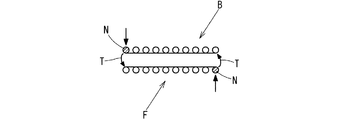
この横編機での筒状編地の編成は、ニードルベッド上を往復するキャリッジの往行時に当該ニードルベッドの編針に給糸して一側面の編地を編成するとともに、キャリッジが復行する時に、図5に示すように前記一側面の編地を編成した編糸が連続する状態で他方のニードルベッドの編針に給糸して他側面の編地を編成する編成コースを交互に繰り返すことにより、両端部が結合された筒状の編地を編成するようにしたものである。
こうした場合、図5に示すように一方のニードルベッドから他方のニードルベッドに移るとき、給糸された編糸のテンション方向が移動するために、一方のニードルベッドの編地端の編針が引き出されやすく、編針が引き出されてしまうと、当該部分のループが小さくなってしまう。
この小さなループが製品に現れてしまうことから、筒状編地製品の品質が低下すると言う問題があった。In order to solve such problems, as previously proposed by the present applicant, a needle bed in which a large number of knitting needles are arranged side by side is arranged with a flat knitting machine in which a pair of front and rear are arranged in a state in which the mouths of the knitting needles face each other. There are some which can be knitted with different tubular knitted fabrics.
In the knitting of the tubular knitted fabric by this flat knitting machine, the yarn is fed to the knitting needles of the needle bed when the carriage reciprocating on the needle bed is knitted, and the carriage returns. Sometimes, as shown in FIG. 5, the knitting course of knitting the knitted fabric of one side is alternately repeated with the knitting course of knitting the knitted fabric of the other side by feeding the knitting needle of the other needle bed in a continuous state. Thus, a tubular knitted fabric having both ends joined together is knitted.
In such a case, as shown in FIG. 5, when moving from one needle bed to the other needle bed, the tension direction of the supplied knitting yarn moves, so that the knitting needle at the end of the knitted fabric of one needle bed is pulled out. If the knitting needle is pulled out easily, the loop of the part will become small.
Since this small loop appears in the product, there is a problem that the quality of the tubular knitted fabric product is deteriorated.
そこで、こうした問題に対処するために、本発明の出願人は、前後一対に配設されたニードルベッドを有する横編機でキャリッジの往復により各ニードルベッドの編針に編地をその両端部が結合した状態で筒状に編成してなる横編機における筒状編地の編成時において、キャリッジの往行時、編地を編成するために編成用制御カムで編針が進出する時は編地の両端及び/または両端寄り部の編針に設けた編針進出防止手段を開放して編針を進出可能にし、キャリッジの復行時には編針進出防止手段を作用させて編地の両端及び/または両端寄り部の編針を退入のみ可能な状態にして筒状編地を編成するようにしたものを先に提案している。(特許文献1)
先の提案にかかる上記方法によれば、編地編成機構のほかに編地の両端部側部分の編み針の進出を防止するために編針の後端部分に編針進出防止手段を、キャリッジには編針進出防止手段を制御するために開放手段を含む大きな制御機構を設けなくてはならず、これら編針進出防止手段および制御機構で構造が複雑になりコストが嵩むという問題があった。 According to the above method according to the previous proposal, in addition to the knitting fabric knitting mechanism, the knitting needle advancement preventing means is provided at the rear end portion of the knitting needle to prevent the knitting needle from advancing at both ends of the knitted fabric, and the knitting needle is provided at the carriage. In order to control the advance prevention means, a large control mechanism including an opening means has to be provided, and there has been a problem that the structure becomes complicated and costs increase with these knitting needle advance prevention means and control mechanism.
また、編地の編み幅を変更するときにはこの編針進出防止手段も移動しなくてはならず
、その設定や調整等の操作に手間が掛かってしまうという問題もあった。
本発明は上記問題点に鑑み提案されたもので、ループ長の揃った品質の高い製品を安価に実施することができる横編機ならびに筒状編地の編成方法を提供することを目的とするものである。In addition, when changing the knitting width of the knitted fabric, the knitting needle advance prevention means must also move, and there is a problem that it takes time to perform operations such as setting and adjustment.
The present invention has been proposed in view of the above problems, and an object of the present invention is to provide a flat knitting machine and a knitting method of a tubular knitted fabric that can implement a high-quality product with a uniform loop length at a low cost. Is.
上記目的を達成するために、本発明にかかる横編機における筒状編地の編成方法は、歯口部を突合せた状態で少なくとも前後一対のニードルベッドを配置し、ニードルベッド上を往復摺動するキャリッジのカム群でニードルベッドに収納された編針の選択された編針を進退摺動させることにより、筒状編地を編成するようにした横編機における筒状編地の編成方法であって、キャリッジが反転後、続いてコースを編成する際に、反転する直前に一方のニードルベッドで編成された編地の少なくとも最後に形成されたループを掛止している編針を、キャリッジのカム群の度山カムで進出を防止した状態にし、これに対面する他方のニードルベッドの編針に編糸を供給してループを形成するようにしたことを最も主要な特徴とするものである。 In order to achieve the above object, a method for knitting a tubular knitted fabric in a flat knitting machine according to the present invention is such that at least a pair of front and rear needle beds are arranged in a state where the mouth portions are abutted, and reciprocatingly slides on the needle bed. A knitting method of a tubular knitted fabric in a flat knitting machine configured to knitted a tubular knitted fabric by moving a selected knitting needle of a knitting needle housed in a needle bed forward and backward by a cam group of a carriage When the course is knitted after the carriage is reversed, the knitting needles that hook the loop formed at least at the end of the knitted fabric knitted with one needle bed immediately before the reverse are knitted, and the cam group of the carriage The main feature is that the advancement is prevented by the mountain cam and the loop is formed by supplying the knitting yarn to the knitting needle of the other needle bed facing the cam.
本発明にかかる横編機における筒状編地の編成方法では、反転する直前に一方のニードルベッドの編針で編成された編地の少なくとも最後のループを掛止している編針を、これに対面する他方のニードルベッドの編針に給糸して編成する間は度山カムで引き込むようにしたことや、編地の少なくとも最後に形成されたループを掛止している編針を、キャリッジのカム群の後行の度山カムで進出を防止した状態にし、これに対面する他方のニードルベッドの編針に編糸を供給してループを形成するより前に先行した位置にある引下げカムにより引き込むようにしたことも特徴とするものである。 In the knitting method of the tubular knitted fabric in the flat knitting machine according to the present invention, the knitting needle that hooks at least the last loop of the knitted fabric knitted with the knitting needle of one needle bed immediately before reversing is faced to this. other during knitting in yarn is fed to knitting needles of the needle beds and that it has to draw in degrees mountain cams, the needles that are engaging at least last formed loop of knitting cam group of a carriage that In the state where the advancement is prevented by the mountain cam at the subsequent stage, the knitting yarn is supplied to the knitting needle of the other needle bed facing the knitting needle so as to be drawn in by the lowering cam before the loop is formed. It is also a feature.
更に本発明にかかる横編機における筒状編地の編成方法では、引下げカムがニードルレイジングカム内に形成された操作カムであることや、引下げカムが先行の度山カムであることも特徴とするものである。 Further, in the knitting method of the tubular knitted fabric in the flat knitting machine according to the present invention, the lowering cam is an operation cam formed in the needle raising cam, and the lowering cam is a preceding cam. To do.
本発明にかかる横編機は、編針を昇降摺動可能に収納したニードルベッドを、その歯口部を突合せた状態で少なくとも前後一対配置し、ニードルベッド上を往復摺動するキャリッジのカム群でニードルベッドの編針の内、選択された編針を進退摺動させることにより、周回状に給糸された編糸で筒状編地を編成するように構成された横編機であって、キャリッジの反転後、続いてコースを編成する際に、反転する直前に一方のニードルベッドで編成された編地の少なくとも最後に形成されたループを掛止している編針を引き下げる引下げカムをニードルレイジングカム内に形成したことを最も主要な特徴とするものである。 The flat knitting machine according to the present invention is a cam group of a carriage in which at least a pair of front and rear needle beds, in which the knitting needles are slidably moved up and down, are faced to each other and are slid back and forth on the needle bed. A flat knitting machine configured to knit a tubular knitted fabric with a knitting yarn fed in a circular shape by sliding a selected knitting needle forward and backward among knitting needles of a needle bed, When the course is subsequently knitted after reversal, a pull-down cam that pulls down the knitting needle that holds at least the loop formed at the end of the knitted fabric knitted with one needle bed immediately before reversing is provided in the needle raising cam. The most important feature is that it was formed in
本発明によれば、キャリッジが反転する直前に形成された編地の少なくとも最後に形成されたループを掛止している編針を、これに対面する編針に給糸して編成する間は、キャリッジのカム群に形成された引下げカムで引き込むようにするので、前記最後に形成されたループを掛止している編針が引き出されることがない。これにより、従来のように当該編針に掛止しているループが小さくなることがなく、筒状編地は、ループ長の揃った品質の高い筒状編地にすることができる。 According to the present invention, while the knitting needle that is hooked at least on the loop formed at the end of the knitted fabric formed immediately before the carriage is reversed is fed to the knitting needle facing the knitting needle, the carriage is knitted. Therefore, the knitting needle that holds the loop formed last is not pulled out. As a result, the loop that is hooked to the knitting needle is not reduced as in the prior art, and the cylindrical knitted fabric can be made into a high-quality cylindrical knitted fabric with a uniform loop length.
また、本発明では編針の引下げカムをキャリッジのカム群に形成するようにしてあるので、本出願人が先に提案したもののように、編地の両端部側部分の編み針の進出を防止するために編針の後端部分に編針進出防止手段を、キャリッジには編針進出防止手段を制御するために開放手段を含む大きな制御機構を設けなくても済み、構造が複雑になることなく安価に実施することが出来る利点がある。 Further, in the present invention, since the knitting needle pulling cam is formed in the cam group of the carriage, in order to prevent the knitting needle from advancing at both end portions of the knitted fabric as previously proposed by the present applicant. In order to control the knitting needle advancement preventing means at the rear end portion of the knitting needle and the carriage, it is not necessary to provide a large control mechanism including an opening means for controlling the knitting needle advancement preventing means, and the structure is inexpensive without being complicated. There is an advantage that can be.
更に、本発明では編針の引下げカムをキャリッジのカム群に形成するようにしてあるので、本出願人が先に提案したもののように、編地の編み幅を変更するときにはこの編針進出防止手段も移動にしなくてもすみ、その設定や調整等の操作に要する手間をなくして生産性を向上させることができる利点もある。 Further, in the present invention, since the knitting needle pulling cam is formed in the cam group of the carriage, when the knitting width of the knitted fabric is changed, the knitting needle advancement preventing means is also provided, as previously proposed by the present applicant. There is also an advantage that productivity can be improved by eliminating the need for movement and eliminating the time and effort required for setting and adjustment.
加えて、編針の引下げカムをキャリッジの先行側の度山カムを利用して筒状編地を編成する方法では、既存の横編機で簡単に実施することができる。
また、キャリッジのニードルレイジングカム内に編針の引下げカムを形成する横編機では、そのキャリッジに大きな変更を施すことなく、本発明を簡単に実施することができる利点もある。In addition, the method of knitting the tubular knitted fabric using the knitting needle pull-down cam on the leading side cam of the carriage can be easily implemented with an existing flat knitting machine.
Further, the flat knitting machine in which the knitting needle pull-down cam is formed in the needle raising cam of the carriage has an advantage that the present invention can be easily implemented without making a major change to the carriage.
以下、本発明にかかる横編機における筒状編地の編成方法及び横編機の好ましい実施形態を図面に基づいて説明する。 Hereinafter, preferred embodiments of a knitting method of a tubular knitted fabric and a flat knitting machine in a flat knitting machine according to the present invention will be described with reference to the drawings.
図1は前後一対に配設されたニードルベッドを有する横編機の要部の側面図であって、図中符号1はこの構編機のニードルベッド部分を全体的に示す。
このニードルベッド部分1はフレーム2の上面に歯口部分を突き合わせ状で略ハの字形に配設されたニードルベッド3・3を設け、各ニードルベッド3・3の上面には多数の編針4・4・・・が昇降摺動可能に設けられている。
この編針4・4・・・は、後述の選針機構Sにより選択された編針4のみがキャリッジ5に内装されたカム群6(図2参照)によって昇降が制御されるようになっている。FIG. 1 is a side view of a main part of a flat knitting machine having a needle bed arranged in a pair of front and rear, and
This
The knitting needles 4, 4,... Are controlled to move up and down by a cam group 6 (see FIG. 2) in which only the knitting needle 4 selected by the needle selection mechanism S described later is housed in the
編針4は、先端部分にラッチ7を有するフック8を形成した編針本体9と、編針本体9の後端部に連結されるニードルジャック10、ニードルジャック10の後部上方にセレタジャック11の各部を順に配設して形成されている。
ニードルジャック10、セレクタジャック11の各部の上面にはキャリッジ5のカム群6によりニードルベッド3・3の針溝17内を昇降操作するためのバット13、14が突出されている。The knitting needle 4 includes a knitting needle main body 9 having a hook 8 having a latch 7 at the front end, a
On the upper surface of each part of the
上記選針機構Sは、各編針4・4・・・のセレクタジャック11の上面には編針の昇降方向に対して隣り合う編針で位相を異ならせたセレクタバット15が設けられており、キャリッジ5内に設けられたアクチュエータ33(図2参照)の起動により、作用されたセレクタバット15の編針4のバット14がキャリッジ5のカム群6でニードルベッド3・3の針溝17内を昇降操作されるようになっている。
In the needle selection mechanism S,
尚、各編針4・4・・・のセレクタジャック11の後部下面には凹嵌部18・19・20が設けられており、この凹嵌部18・19・20がニードルベッド3を貫通して設けたワイヤ21に択一的に掛止することにより、例えばワイヤ21が凹嵌部20に掛合している時はウエルト位置、ワイヤ21が凹嵌部19に掛合している時はニット位置、ワイヤ21が凹嵌部18に掛合している時はタック位置に保持されるようになっている。
In addition, concave
一方、各ニードルベッド3上を摺動し、選択された編針4を昇降操作するキャリッジ5 のカム群6は、図2に示すようになっている。
この図2では、各ニードルベッド3上を摺動するキャリッジ5のカム群6を上から透視した状態にしてあり、符号Fは前側のキャリッジ5のカム群6を、符号Bは後側のキャリッジ5のカム群6をそれぞれ示す。On the other hand, the
In FIG. 2, the
キャリッジ5のカム群6は、ニードルレイジングカム22の上方に天山カム23を設け、天山カム23の両側方に上下一対の固定ガイドカム24を設けるとともに、天山カム23と固定ガイドカム24との間に度山カム25が昇降操作可能に設けてある。
この度山カム25の昇降操作は、図外の制御装置のプログラムに設定された昇降量の信号で駆動されるステッピングモータにより行なわれる。
この度山カム25は、キャリッジ5の進行方向下手側を先行の度山カム25aとし、上手側を後行の度山カム25bとし、編成時は主として後行側の度山カム25bが作用する。The
The raising / lowering operation of the
The
キャリッジ5のカム群6の天山カム23とニードルレイジングカム22との間には図上前側(F)のキャリッジ5のカム群6に示すように、ループ形成のための編針軌道L1(ニットルート)が形成されるとともに、もう一つの編針軌道L2を形成する溝があり、これらのカム以外に6個の軌道切換カム26、27、28、29、30、31が設けられている。
上記軌道切換カム26〜31のそれぞれはキャリッジ5内に取付けられた図示しないソレノイドの作用によって出没し、その位置を変位させることにより、上記編針軌道L1またはL2を任意に選択することができる。As shown in the
Each of the
従って、選針された編針4は、編針軌道L1またはL2のいずれかを通過することにより、ニードルベッド3の針溝17を昇降操作されることになる。
また、詳細の図示は省略したが、ニードルレイジングカム22の下方には、上記ウエルト位置、ニット位置、タック位置にあるセレクタバット15に対応させてニードルプレッサ32が設けられるとともに、その左右に配設された固定カム24の下方部分に上記選針機構Sのアクチュエータ33が設けてある。Therefore, the selected knitting needle 4 moves up and down the
Although not shown in detail, a
上記のように構成された横編機で本発明にかかる筒状編地の編成方法を次に説明するが、以下の筒状編地の編成方法ではその編成の周回方向を、図5に示すように反時計回り方向とし、図3はキャリッジ5が矢印Aで示す右から左に摺動して後側ニードルベッド3の編針4に編糸をヤーンフィーダ34から供給してループを形成する往行を示す。
往行は、前側ニードルベッド3で編成を終えたキャリッジ5が反転して右方から左方に摺動し、後側ニードルベッド3で編地が形成されることになる。
この往行時には、後側のキャリッジ5の軌道切換カム26、28が突出して通路をブロックするので、編地の編成領域内の編針として先行側の選針機構Sのアクチュエータ33で選針された編針4は図中一点鎖線で示す編針軌道L1を通る。Next, a method for knitting a tubular knitted fabric according to the present invention will be described with the flat knitting machine configured as described above. In the following knitting method for a tubular knitted fabric, the direction of knitting is shown in FIG. 3, the
In the forward direction, the
At this time, the
一方、前側のキャリッジ5の軌道切換カム26、29、30が突出して通路をブロックし、先行側の選針機構Sのアクチュエータ33で選針された、図5中右側のループNを掛止している前側ニードルベッド3の編針4は、図3中、点線で示す編針軌道L2を通る。
したがって、後側ニードルベッド3の編針4が後側のキャリッジ5のカム群6のニードルレイジングカム22でニット位置に上昇する間に、編針軌道L2を通る前側のニードルベッド3の編み針4が天山カム23の下方近傍にまで押し上げられる。On the other hand, the
Therefore, while the knitting needle 4 of the rear needle bed 3 is raised to the knit position by the
続いて、選針された後側ニードルベッド3の編針4が天山カム23の下端水平部分中間位置に下降すると、ヤーンフィーダ34から編糸が供給されるのであるが、このとき、軌道切換カム29で案内される編針軌道L2を通る前側ニードルベッド3の編針4はすでに下降しており、ヤーンフィーダ34から供給された編糸が前側ニードルベッド3の編針4にくわえられることがない。
後側ニードルベッド3の編針4が後行側の度山カム25bでさらに引き込まれると、前コースで形成された旧ループがフック8部分をノックオーバーして新たなループが形成される。Subsequently, when the selected knitting needle 4 of the rear needle bed 3 is lowered to the middle position of the lower end horizontal portion of the
When the knitting needle 4 of the rear needle bed 3 is further pulled by the
こうした往行での編地の編成時、キャリッジ5が反転して編地の編成が前側ニードルベッド3から後側ニードルベッド3に移るときは、キャリッジ5が反転する直前に前側ニードルベッド3で編成された編地の最後に形成されたループ(図5中右側のN)を掛止している編針4を、これに対面する後側ニードルベッド3の編針4に給糸されてループが形成されるまでは、前側キャリッジ5の後行側の度山カム25bの下端部分で引き下げるので、前側のニードルベッド3の編針4が引き出されることがない。
したがって、ループ(図5中右側のN)の目が詰まるのが抑制される。
斯くして後側ニードルベッド3での編成が終了し、その編成領域外(図上左方)に出ると、キャリッジ5が反転して左方から右方に摺動し、前側のニードルベッドで編地を編成する図4に示す復行となる。When the knitted fabric is knitted in such an outward direction, when the
Therefore, clogging of the loop (N on the right side in FIG. 5) is suppressed.
Thus, when the knitting in the rear needle bed 3 is completed and the knitting area is out of the knitting area (left side in the figure), the
図4の復行時には、前側のキャリッジ5の軌道切換カム27、29が突出して通路をブロックし、先行側の選針機構Sのアクチュエータ33で選針された編成領域の編針4は図中一点鎖線で示す編針軌道L1を通り、後側のキャリッジ5の軌道切換カム27、28、31が突出して通路をブロックするので、先行側の選針機構Sのアクチュエータ33で選針された後側ニードルベッド3の、図5中左側のループNを掛止している編針4は図中点線で示す編針軌道L2を通るようになる。
キャリッジ5の反転後、前側のニードルベッド3で編地を編成する際に、反転する直前に後側ニードルベッド3で編成された編地の最後に形成された端のループ(図5における左側のN)を掛止している編針4に対面する前側ニードルベッド3の編針4が、前側のキャリッジ5の先行側の選針機構Sのアクチュエータ33で選針され、前側のキャリッジ5のカム群6のニードルレイジングカム22でニット位置に上昇する間に、後側ニードルベッド3の編針軌道L2を通る編み針4が天山カム23の下方近傍にまで押し上げられる。4, the
When the knitted fabric is knitted with the front needle bed 3 after the
続いて、前側ニードルベッド3の編針4が天山カム23の下端水平部分中間位置に下降してヤーンフィーダ34から編糸が供給されるのであるが、このとき、軌道切換カム28で案内される後側ニードルベッド3の編針4はすでに下降しており、供給された編糸が後側ニードルベッド3の編針4にくわえられることがないのは往行時と同様である。
前側ニードルベッド3の編針4が後行側の度山カム25bでさらに引き込まれると、前コースで形成された旧ループがノックオーバーして新たなループが形成される。
この前側ニードルベッド3の編針4が後行側の度山カム25bで引き込まれるとき、これに対向する後側ニードルベッド3の編針4(後側ニードルベッド3で編成された編地の最後に形成されたコースの端の編針)が後行側の度山カム25bで引き込まれる。Subsequently, the knitting needle 4 of the front needle bed 3 is lowered to the middle position of the lower end horizontal portion of the
When the knitting needle 4 of the front needle bed 3 is further pulled by the trailing
When the knitting needle 4 of the front needle bed 3 is pulled by the trailing
これにより、後側のニードルベッド3の編針4が引き出されることがないため、ループ(図5中左側のN)の目が詰まるのが抑制される。
そして、前側ニードルベッド3での編成が終了し、その編成領域外(図上右方)に出ると、キャリッジ5が再び反転して右方から左方に摺動して前側のニードルベッド3で編地を編成する前述の往行となる。
以後、上記往行と復行の編成が交互に連続して行なわれる。
こうした動作が編地の両端で繰り返して行なわれることにより、前後のニードルベッド3の編針4に周回状に編糸を供給して横編機で筒状編地を編成したときでも、キャリッジ5が反転する部分のループ4が詰まって小さくなるのが抑制される。Thereby, since the knitting needle 4 of the rear needle bed 3 is not pulled out, clogging of the loop (N on the left side in FIG. 5) is suppressed.
Then, when the knitting in the front needle bed 3 is finished and the knitting area is out of the knitting area (right side in the figure), the
Thereafter, the forward and backward knitting are alternately and continuously performed.
Such an operation is repeatedly performed at both ends of the knitted fabric, so that the
尚、上記実施例では、選針機構Sとニードルレイジングカム22内に設けた軌道切換カム26〜31を操作することにより、キャリッジが反転する直前に形成された少なくとも一つの終端のループを掛止した編針を編針軌道L2に案内し、上記編針に対面するニードルベッド3の編針4がループを形成する間は、度山カム25bで編針4が引き出されるのを防止するようにしてある。
しかし、こうしたものに限られず、例えば選針機構Sとニードルプレッサ32との協働により選針された端のループを形成する編針のバットが後行側の度山カム25bに到達するまでの間をニードルプレッサにより押圧させてニードルレイジングカムの作用を受けずに通過させ、その後ニードルプレッサの押圧から解放させて後行の度山カム25bで引き込むことができるようにニードルプレッサを設計することもできる。
この場合は上記編針軌道L2と異なる軌道を通る事になるが編針が引き上げられるのを同様に防ぐことができる。In the above embodiment, at least one end loop formed immediately before the carriage is reversed is hooked by operating the needle selection mechanism S and the
However, the present invention is not limited to this, for example, until the butt of the knitting needle that forms the loop of the end selected by the cooperation of the needle selection mechanism S and the
In this case, the knitting needle can be prevented from being pulled up although it passes through a different track from the knitting needle track L2.
また、本発明の反転する直前に編成された編地の端のループを掛止している編針4の引き込み量は、引き出されるのを防止できる程度であればよく、必ずしも引き込むものに限られない。
更に、上記実施例では、キャリッジ5が反転する直前に編成された編地のループを掛止している編針4を、これに対面する編針4に給糸して編成する間は、この編地の端の編針4に対面する1本の編針4を度山カム25bで引き込むようにしてあるが、こうしたものに限られず、側端の編針数本を引き込むようにすることもできる。Further, the pull-in amount of the knitting needle 4 that holds the loop at the end of the knitted fabric knitted just before reversal of the present invention is not limited to the pull-in amount as long as it can be prevented from being pulled out. .
Further, in the above-described embodiment, the knitting needle 4 that holds the loop of the knitted fabric knitted just before the
本実施例は主として、筒状編地の一方の編地のコース編成を行なった後、キャリッジを反転させて他方の編地のコース編成を行なう際に、他方の編地でのループの形成よりも先行させて、反転する直前に編成されたループを掛止する編針を再度引き下げる操作カムをカム群のニードルレイジングカム内に設けた編機の例を示す。
この横編機は、詳細の図示は省略したが、スライダが昇降摺動することによりフック部分を開閉するようにした複合編針である点と、後述する図6に示すキャリッジのカム群を除くその他の構成は上記実施例1と略同様に構成されている。
キャリッジ5のカム群6は、図6に示すように、ニードルレイジングカム22の上方に天山カム23を設け、天山カム23の両側方(キャリッジの進行方向に対して前後方向)に上下一対の固定ガイドカム24を設けるとともに、天山カム23と固定ガイドカム24との間に度山カム25が昇降操作可能に設けてある。In the present embodiment, after the course knitting of one knitted fabric of the tubular knitted fabric is performed and then the carriage is reversed and the course knitting of the other knitted fabric is performed, the formation of the loop in the other knitted fabric is An example of a knitting machine in which an operation cam that pulls down again a knitting needle that hooks a loop knitted just before reversing is provided in a needle raising cam of a cam group is also shown.
This flat knitting machine is not shown in detail, but it is a composite knitting needle that opens and closes the hook portion by sliding the slider up and down, and other than the carriage cam group shown in FIG. The configuration is substantially the same as that of the first embodiment.
As shown in FIG. 6, the
この度山カム25の昇降操作は、図外の制御装置のプログラムに設定された昇降量の信号で駆動されるステッピングモータにより行なわれる。
この度山カム25は、キャリッジ5の進行方向下手側を先行の度山カム25aとし、上手側を後行の度山カム25bとし、編成時は主として後行側の度山カム25bが度目設定用として作用する。The raising / lowering operation of the
The
キャリッジ5のカム群6の天山カム23とニードルレイジングカム22との間には例えば図6の下に示す前側(F)のキャリッジ5のカム群6に示すように、ループ形成のための編針軌道L1(ニットルート)が形成されるとともに、ニードルレイジングカム22内にもう一つの編針軌道L2(コントロールルート)が形成されている。
ニットルートの編針軌道L1は、台形に形成されたニードルレイジングカム22の上面部分で天山カム23の頂部の中心線を対称とする前後位置に三角形をした出没カム35・35を設けて形成してあり、これら出没カム35・35は図外の制御装置のプログラムからの信号により、編地の編成時に先行側の出没カムが突出するようになっている。For example, as shown in the
The knitting needle track L1 of the knit root is formed by providing
一方、ニードルレイジングカム22内に形成される編針軌道L2は、台形に形成されたニードルレイジングカム22の中間高さ位置に前後に貫通した通路36を形成し、当該通路36の中側部分36aを上部に広げた状態にするとともに、その広げられた中側部分36aに引下げカムとして下向き台形の操作カム37をニードルレイジングカム22と一体に形成してある。
そして、編針軌道L2のニードルレイジングカム22内の高さは図7に示すようになっている。On the other hand, the knitting needle track L2 formed in the
The height of the knitting needle track L2 in the
即ち、図7(a)は図6におけるX−X線断面図、図7(b)は図6におけるY−Y線断面であって、ニードルレイジングカム22と度山カム25並びに突出した出没カム35の突出時の高さは等しい高さにしてあり、上記通路36の中側部分36aは地板38部分と等しい高さゼロ(略面一)にし、通路36の前後出入口部分36bはニードルレイジングカム22と地板38との中間の高さ(ハーフ高さ)にしてある。
そして、アクチュエータ33で選針された編成領域の編針4は、そのセレクタバット15がニードルプレッサ32の作用を受けることによりループ形成のための編針軌道L1を通過するか、コントロールルートの編針軌道L2を通過するかが決定される。7A is a cross-sectional view taken along the line XX in FIG. 6, and FIG. 7B is a cross-sectional view taken along the line Y-Y in FIG. 6, and the
The knitting needle 4 in the knitting area selected by the actuator 33 passes through the knitting needle track L1 for loop formation when the
ニードルプレッサ32は、前後の度山カム25a・25bの動作範囲をカバーするように長く形成されたウエルトプレッサ39と、その上方に前記通路36の前後出入口部分36bに対応する部分に出退可能に形成されたハーフ高さのハーフプレッサ40とを備え、ハーフプレッサ40をAポジションとし、ウエルトプレッサ39をBポジションとしたときにその中間部分に図6に点線41で示すハーフ(H)ポジションが形成されている。
The
上記Aポジションのハーフプレッサ40が地板38と略等しい高さ(高さゼロ)に沈んでいるとき及び編針4のセレクタバット15が点線41で示すハーフポジションにあるとき、即ち、アクチュエータ33で選針された編針4がニードルプレッサ32の作用を受けないとき、編針4はニットルートであるの編針軌道L1を通り、編針4がAポジションのハーフプレッサ40の作用を受けるときにはコントロールルートである編針軌道L2を通る。
因みに、Bポジションのウエルトプレッサ39が編針4のセレクタバット15に作用する時には、その編針4はキャリッジ5のカム群6の作用を受けることなく通過する。When the half-
Incidentally, when the B
上記のように構成された横編機で本発明にかかる筒状編地の編成方法を次に説明する。 以下の筒状編地の編成方法では実施例1と同様、編成の周回方向を図5に示すように反時計回り方向とし、図8はキャリッジ5が矢印Aで示す右から左に摺動して後側ニードルベッド3の編針4に編糸をヤーンフィーダ34から供給してループを形成する往行を示す。
往行は、前側ニードルベッド3で編成を終えたキャリッジ5が反転して右方から左方に摺動し、後側ニードルベッド3で編地が形成される。
この往行時には、後側(B)のキャリッジ5の先行側の出没カム35が突出しており、先行側の選針機構Sのアクチュエータ33で選針された後側ニードルベッド3の編針4のセレクタバット15はニードルプレッサ32の作用を受けず、当該編針4のバット13は、ニードルレイジングカム22と出没カム35との作用を受けて図8中に一点鎖線で示すニットルートである編針軌道L1を通る。Next, a method for knitting a tubular knitted fabric according to the present invention using the flat knitting machine configured as described above will be described. In the following knitting method of the tubular knitted fabric, as in the first embodiment, the turning direction of the knitting is set to the counterclockwise direction as shown in FIG. 5, and FIG. FIG. 3 shows the outward travel in which a knitting yarn is supplied from the
In the forward direction, the
At the time of this travel, the leading and retracting
一方、図5中右側のループNを掛止している前側ニードルベッド3の編針4は、前側のキャリッジ5の先行側の選針機構Sで選針され、その編針4のバット13がハーフプレッサ40の作用を受けてハーフ位置(中間高さ位置)に押込まれる。
するとその編針4のバット13は、図8の前側(F)のキャリッジ5のカム群6のニードルレイジングカム22内に形成された通路36中に点線で示すコントロールルートの編針軌道L2を通過する。
ここで、後側ニードルベッド3の編針4が、後側(B)のキャリッジ5のカム群6のニードルレイジングカム22及び出没カム35でニット位置に上昇する間に、前側(F)のキャリッジ5のカム群6内の編針軌道L2を通る前側のニードルベッド3の編み針4は編針の引下げカムを構成する操作カム37部分で引下げられる。On the other hand, the knitting needle 4 of the front needle bed 3 engaging the loop N on the right side in FIG. 5 is selected by the needle selection mechanism S on the leading side of the
Then, the
Here, while the knitting needle 4 of the rear needle bed 3 is raised to the knit position by the
続いて、後側ニードルベッド3の選針された編針4が下降して天山カム23の下端の水平部分の中間位置になると、ヤーンフィーダ34から編糸が供給される。
このとき、前側(F)のキャリッジ5の通路36で案内される編針軌道L2を通る前側ニードルベッド3の編針4が引下げカムである操作カム37で下降した状態になっており、後側ニードルベッド3の編針4が後行側の度山カム25bでさらに引き込まれると、前コースで形成された旧ループがフック部分をノックオーバーされて新たなループが形成される。Subsequently, when the selected knitting needle 4 of the rear needle bed 3 is lowered to the middle position of the horizontal portion at the lower end of the
At this time, the knitting needle 4 of the front needle bed 3 passing through the knitting needle track L2 guided by the
こうした往行での編地の編成時、キャリッジ5が編地の編成が前側ニードルベッド3から後側ニードルベッド3に反転するときは、キャリッジ5が反転する直前に前側ニードルベッド3で編成された編地の最後に形成されたループ(図5中右側のN)を掛止している編針4が、これに対面する後側ニードルベッド3の編針4に給糸され編成されるまえに、前側(F)のキャリッジ5の操作カム37で引き下げられているので、キャリッジ5の反転にともなって、ヤーンフィーダ34の給糸方向が反転する際に、編糸のテンションが高
まり、その結果、反転直前に形成されたループから編糸が引き出されてループが詰んでもこれを修正して編地のループ長を揃えることができる。During knitting of the knitted fabric in such a forward direction, when the knitting of the knitted fabric is reversed from the front needle bed 3 to the rear needle bed 3, the
そして、後側ニードルベッド3の編針4に給糸され編成する間、前側(F)のキャリッジ5の後行側の度山カム25bで引き下げられているので、後側ニードルベッド3の編針4が度山カム25bで引き込まれるとき、前側のニードルベッド3の前記編針4が引き出されることがない。
したがって、ループ(図5中右側のN)の目が詰まることがなくなる。
斯くして後側ニードルベッド3での編成が終了し、その編成領域外(図上左方)に出ると、キャリッジ5が反転して図9に矢印Bで示す左方から右方に摺動し、前側のニードルベッド3で編地を編成する復行となる。While the yarn is fed to the knitting needle 4 of the rear needle bed 3 and knitting, the knitting needle 4 of the rear needle bed 3 is pulled down by the
Therefore, the eyes of the loop (N on the right side in FIG. 5) are not clogged.
Thus, when the knitting in the rear needle bed 3 is finished and the knitting area is out of the knitting area (left side in the figure), the
図9の復行時には、前側(F)のキャリッジ5の先行側の出没カム35が突出しており、先行側の選針機構Sのアクチュエータ33で選針された編針4のセレクタバット15はニードルプレッサ32の作用を受けず、当該編針4のバット13は、ニードルレイジングカム22と出没カム35との作用を受けて図9の前側(F)のキャリッジ5のカム群6に一点鎖線で示すニットルートである編針軌道L1を通る。
一方、図5中左側のループNを掛止している後側ニードルベッド3の編針4は、後側のキャリッジ5の先行側の選針機構Sのアクチュエータ33で選針され、その編針4のバット13がハーフプレッサ40の作用を受けてハーフ位置に押込まれる。
するとその編針4のバット13は、図9の後側(B)のキャリッジ5のカム群6内に点線で示すようにニードルレイジングカム22内に形成された通路36に形成されたコントロールルートの編針軌道L2を通過する。
ここで、前側ニードルベッド3の編針4が、前側のキャリッジ5のカム群6のニットルートである編針軌道L1のニードルレイジングカム22及び出没カム35でニット位置に上昇する間に、編針軌道L2を通る後側のニードルベッド3の編み針4は編針の引下げカムを構成する操作カム37部分で引下げられる。9, the leading and trailing
On the other hand, the knitting needle 4 of the rear needle bed 3 that is engaged with the left loop N in FIG. 5 is selected by the
Then, the
Here, while the knitting needle 4 of the front needle bed 3 is raised to the knit position by the
続いて、前側ニードルベッド3の選針された編針4が出没カム35の頂部から下降して天山カム23の下端の水平部分の中間位置になると、ヤーンフィーダ34から編糸が供給される。
このとき、後側(B)キャリッジ5の通路36で案内される編針軌道L2を通る後側ニードルベッド3の編針4は引下げカムである操作カム37で下降した状態になっており、前側ニードルベッド3の編針4が後行側の度山カム25bでさらに引き込まれると、前コースで形成された旧ループがフック部分をノックオーバーされて新たなループが形成される。Subsequently, when the selected knitting needle 4 of the front needle bed 3 descends from the top of the retracting
At this time, the knitting needle 4 of the rear needle bed 3 passing through the knitting needle track L2 guided by the
こうした複行での編地の編成時、キャリッジ5が反転して編地の編成が後側ニードルベッド3から前側ニードルベッド3に移るときは、キャリッジ5が反転する直前に後側ニードルベッド3で編成された編地の最後に形成されたループ(図5左側のN)を掛止している編針4が、これに対面する前側ニードルベッド3の編針4に給糸され編成されるまえに、後側(B)のキャリッジ5の操作カム37で引き下げられているので、キャリッジ5の反転にともなって、ヤーンフィーダ34の給糸方向が反転する際に、編糸のテンションが
高まり、その結果、反転直前に形成されたループから編糸が引き出されてループが詰んでもこれを修正して編地のループ長を揃えることができる。When knitting the knitted fabric in such a double row, when the
そして、前側ニードルベッド3の編針4に給糸され編成する間、後側(B)のキャリッジ5の後行側の度山カム25bで引き下げられているので、前側ニードルベッド3の編針4が度山カム25bで引き込まれるとき、後側のニードルベッド3の前記編針4が引き出されることがない。
したがって、キャリッジ5の反転にともなうヤーンフィーダ4の給糸方向の反転時、ループ(図5中左側のN)の目が詰まることがなくなる。
斯くして、前側ニードルベッド3での編成が終了し、その編成領域外(図上右方)に出ると、キャリッジ5が再び反転して右方から左方に摺動して前側のニードルベッド3で編地を編成する前述の往行となる。
以後、上記往行と復行の編成が交互に連続して行なわれる。While the yarn is fed to the knitting needle 4 of the front needle bed 3 and knitting, the knitting needle 4 of the front needle bed 3 is pulled down by the
Therefore, when the yarn feeder 4 is reversed in the yarn feeding direction as the
Thus, when the knitting in the front needle bed 3 is completed and the knitting area is out of the knitting area (right side in the figure), the
Thereafter, the forward and backward knitting are alternately and continuously performed.
こうした動作が編地の両端で繰り返して行なわれることにより、前後のニードルベッド3の編針4に周回状に編糸を供給して横編機で筒状編地を編成するとき、キャリッジ5の反転にともなって、ヤーンフィーダ34の給糸方向が反転する際に、編糸のテンションが高まり、その結果、反転直前に形成されたループから編糸が引き出されてループが詰んでもこれを修正して編地のループ長を揃えることができる。
By repeating these operations at both ends of the knitted fabric, the
尚、本例では、キャリッジ5が反転する直前に編成された編地のループを掛止している編針4を、これに対面する編針4に給糸して編成する間は、この編地の端の編針4に対面する編針4を編針の操作カム(引下げカム)37で引き込むようにしてあるが、こうしたものに限られず、例えば、キャリッジが反転する直前に一方のニードルベッドで編成された編地の最後に形成されたループ(図5中右側のN)を掛止している編針を、これに対面する他方のニードルベッドの編針に給糸され編成する前に、一方のニードルベッドのキャ
リッジの先行側の度山カムで引き下げておくことにより、キャリッジ5の反転にともなって、ヤーンフィーダ34の給糸方向が反転する際に、編糸のテンションが高まり、その結果、反転直前に形成されたループから編糸が引き出されてループが詰んでもこれを修正して編地のループ長を揃えることができる。In this example, while the knitting needle 4 that is hooked on the loop of the knitted fabric knitted just before the
この場合、一方のニードルベッドのキャリッジの先行側の度山カムも引下げカムとして作用する。
こうした度山カムも引下げカムとして作用させる場合、上記操作カムとも併用させることが望ましい。
なお、実施例1では度山カムでキャリッジが反転する直前に一方のニードルベッドで編成された編地の最後に形成されたループを掛止している編針を引き下げるようにし、上記実施例2では望ましい形態として、先行側の度山カムと引下げカムとを併用して編針を引き下げるようにしてあるが、引下げカムの作用だけでも前記編針を引き下げてキャリッジが反転する直前に一方のニードルベッドで編成された編地の最後に形成されたループの目が詰まるのを抑制することができる。In this case, the mountain cam on the leading side of the carriage of one needle bed also acts as a pull-down cam.
In such a case, when the mountain cam also acts as a lowering cam, it is desirable to use it together with the operation cam.
In the first embodiment, the knitting needle that holds the loop formed at the end of the knitted fabric knitted by one needle bed is pulled down immediately before the carriage is reversed by the angle cam, and in the second embodiment, the knitting needle is pulled down. As a desirable form, the knitting needle is pulled down by using both the leading cam and the pulling cam on the leading side, but the knitting needle is pulled down by just the action of the pulling cam and the knitting needle is knitted on one needle bed just before the carriage is reversed. It is possible to suppress clogging of the loop formed at the end of the formed knitted fabric.
また、引下げカムで引きさげられるキャリッジ5が反転する直前に編成された編地のループの編針は1本に限られず数本を引き込むようにすることもできる。
更に、上記操作カムは固定されたものに限られず、高さを変更できるようにすることもできる。こうした場合には横編機のゲージや編糸の種類等に合わせたきめ細かな設定を行なうことができる。Further, the number of knitting needles of the loop of the knitted fabric knitted immediately before the
Further, the operation cam is not limited to a fixed one, and the height can be changed. In such a case, fine setting according to the gauge of the flat knitting machine, the type of knitting yarn, and the like can be performed.
3・・・ニードルベッド
4・・・編針
5・・・キャリッジ
6・・・カム群
22・・・ニードルレイジングカム
25a・・・先行度山カム(引下げカム)
37・・・操作カム(引下げカム)DESCRIPTION OF SYMBOLS 3 ... Needle bed 4 ...
37 ... Operation cam (pull-down cam)
Claims (6)
Priority Applications (1)
| Application Number | Priority Date | Filing Date | Title |
|---|---|---|---|
| JP2007510393A JP4944015B2 (en) | 2005-03-25 | 2006-03-17 | Method for knitting tubular knitted fabric in flat knitting machine and flat knitting machine |
Applications Claiming Priority (6)
| Application Number | Priority Date | Filing Date | Title |
|---|---|---|---|
| JP2005088279 | 2005-03-25 | ||
| JP2005088279 | 2005-03-25 | ||
| JP2005232983 | 2005-08-11 | ||
| JP2005232983 | 2005-08-11 | ||
| PCT/JP2006/305381 WO2006103957A1 (en) | 2005-03-25 | 2006-03-17 | Method of knitting cylindrical fabric in weft knitting machine and weft knitting machine |
| JP2007510393A JP4944015B2 (en) | 2005-03-25 | 2006-03-17 | Method for knitting tubular knitted fabric in flat knitting machine and flat knitting machine |
Publications (2)
| Publication Number | Publication Date |
|---|---|
| JPWO2006103957A1 JPWO2006103957A1 (en) | 2008-09-04 |
| JP4944015B2 true JP4944015B2 (en) | 2012-05-30 |
Family
ID=37053218
Family Applications (1)
| Application Number | Title | Priority Date | Filing Date |
|---|---|---|---|
| JP2007510393A Active JP4944015B2 (en) | 2005-03-25 | 2006-03-17 | Method for knitting tubular knitted fabric in flat knitting machine and flat knitting machine |
Country Status (6)
| Country | Link |
|---|---|
| US (1) | US7716954B2 (en) |
| EP (1) | EP1867768B1 (en) |
| JP (1) | JP4944015B2 (en) |
| KR (1) | KR101223919B1 (en) |
| CN (1) | CN101146942B (en) |
| WO (1) | WO2006103957A1 (en) |
Families Citing this family (17)
| Publication number | Priority date | Publication date | Assignee | Title |
|---|---|---|---|---|
| JP5079682B2 (en) * | 2008-12-29 | 2012-11-21 | 株式会社島精機製作所 | Flat knitting machine for tubular knitted fabric and knitting method of tubular knitted fabric |
| JP5431002B2 (en) * | 2009-04-03 | 2014-03-05 | 株式会社島精機製作所 | Flat knitting machine for tubular knitted fabric knitting |
| CN102277681A (en) * | 2011-08-09 | 2011-12-14 | 陶春明 | Zhongshan triangle for computerized flat knitting machine |
| CN102383256A (en) * | 2011-09-29 | 2012-03-21 | 陶春明 | Triangular part for computerized flat knitting machine |
| EP2875745A4 (en) * | 2012-07-17 | 2016-04-06 | Shima Seiki Mfg | Shoe upper and method for producing shoe upper |
| JP2015028226A (en) * | 2013-07-30 | 2015-02-12 | 株式会社島精機製作所 | Method of knitting knitted fabric |
| EP3128055B1 (en) * | 2015-08-05 | 2018-09-19 | H. Stoll AG & Co. KG | Cam system for a flat knitting machine and flat knitting machine |
| US10368590B2 (en) | 2015-11-03 | 2019-08-06 | Nike, Inc. | Flat-knit support garment for upper torso |
| JP2017089043A (en) * | 2015-11-09 | 2017-05-25 | 株式会社福原精機製作所 | Knitting method and knitting mechanism for circular knitting machine and the circular knitting machine |
| US10612169B2 (en) | 2017-04-13 | 2020-04-07 | Precision Fukuhara Works, Ltd. | Knitting mechanism for circular knitting machine and the circular knitting machine |
| US10415164B2 (en) | 2017-05-02 | 2019-09-17 | Nike, Inc. | Upper-torso garment with three-dimensional knit structures |
| US10145042B2 (en) | 2017-05-02 | 2018-12-04 | Nike, Inc. | Upper-torso garment with tubular-jacquard knit structure |
| US10179960B2 (en) | 2017-05-02 | 2019-01-15 | Nike, Inc. | Upper-torso garment with tubular-jacquard knit structure |
| US10912340B2 (en) | 2017-05-02 | 2021-02-09 | Nike, Inc. | Upper-torso garment with tubular-jacquard knit structure |
| JP7233309B2 (en) * | 2018-07-13 | 2023-03-06 | 株式会社島精機製作所 | flat knitting machine |
| US11142854B2 (en) | 2018-10-03 | 2021-10-12 | Nike, Inc. | Upper-torso garment with three-dimensional knit structures |
| US11064279B2 (en) * | 2019-10-09 | 2021-07-13 | Microsoft Technology Licensing, Llc | Headphone earcup including seamless cover |
Citations (3)
| Publication number | Priority date | Publication date | Assignee | Title |
|---|---|---|---|---|
| JP2631923B2 (en) * | 1991-09-24 | 1997-07-16 | 株式会社島精機製作所 | Knitting device for tubular knitted fabric in flat knitting machine |
| JP2700203B2 (en) * | 1991-10-04 | 1998-01-19 | 株式会社島精機製作所 | Transfer method and apparatus for flat knitting machine |
| JP3292836B2 (en) * | 1998-05-06 | 2002-06-17 | 株式会社島精機製作所 | Flat knitting machine |
Family Cites Families (11)
| Publication number | Priority date | Publication date | Assignee | Title |
|---|---|---|---|---|
| DE2939639A1 (en) * | 1978-10-03 | 1980-04-24 | Bentley Alemannia Ltd | FLAT KNITTING MACHINE |
| DE3220055A1 (en) * | 1982-05-27 | 1983-12-01 | Universal Maschinenfabrik Dr. Rudolf Schieber GmbH & Co KG, 7081 Westhausen | KNITTED CROSSBODY LOCK FOR V-BED FLAT KNITTING MACHINES WITH SLIDING NEEDLES |
| DE3334040C2 (en) * | 1983-09-21 | 1986-03-13 | H. Stoll Gmbh & Co, 7410 Reutlingen | Single or multiple lock system for flat knitting machines |
| DE3433628C2 (en) * | 1984-09-13 | 1986-12-18 | H. Stoll Gmbh & Co, 7410 Reutlingen | Lock system for flat knitting machines and method for the combined formation and transfer of stitches on flat knitting machines |
| DE3537612C2 (en) * | 1985-10-23 | 1994-07-28 | Stoll & Co H | Lock system for flat knitting machines |
| CH671977A5 (en) * | 1986-12-01 | 1989-10-13 | Dubied & Cie Sa E | |
| US5305619A (en) * | 1990-03-26 | 1994-04-26 | Shima Seiki Mfg. Ltd. | Stitch increasing method and cams for flat knitting machine having stitch increasing function |
| JP3022322U (en) * | 1995-09-01 | 1996-03-22 | シルバー精工株式会社 | Flat knitting machine |
| US6591430B1 (en) * | 2001-11-13 | 2003-07-15 | Wilson Harris Sledge | Head and neck support apparatus |
| JP4015982B2 (en) * | 2003-10-10 | 2007-11-28 | 株式会社島精機製作所 | Cam apparatus for knitting fabric |
| JP4336305B2 (en) * | 2004-12-27 | 2009-09-30 | 株式会社島精機製作所 | Combined cam system |
-
2006
- 2006-03-17 CN CN2006800097320A patent/CN101146942B/en active Active
- 2006-03-17 KR KR1020077022441A patent/KR101223919B1/en active IP Right Grant
- 2006-03-17 WO PCT/JP2006/305381 patent/WO2006103957A1/en active Application Filing
- 2006-03-17 US US11/886,997 patent/US7716954B2/en not_active Expired - Fee Related
- 2006-03-17 EP EP06729371.2A patent/EP1867768B1/en active Active
- 2006-03-17 JP JP2007510393A patent/JP4944015B2/en active Active
Patent Citations (3)
| Publication number | Priority date | Publication date | Assignee | Title |
|---|---|---|---|---|
| JP2631923B2 (en) * | 1991-09-24 | 1997-07-16 | 株式会社島精機製作所 | Knitting device for tubular knitted fabric in flat knitting machine |
| JP2700203B2 (en) * | 1991-10-04 | 1998-01-19 | 株式会社島精機製作所 | Transfer method and apparatus for flat knitting machine |
| JP3292836B2 (en) * | 1998-05-06 | 2002-06-17 | 株式会社島精機製作所 | Flat knitting machine |
Also Published As
| Publication number | Publication date |
|---|---|
| KR20070113269A (en) | 2007-11-28 |
| EP1867768B1 (en) | 2016-03-09 |
| WO2006103957A1 (en) | 2006-10-05 |
| CN101146942B (en) | 2010-06-09 |
| US20090314037A1 (en) | 2009-12-24 |
| CN101146942A (en) | 2008-03-19 |
| JPWO2006103957A1 (en) | 2008-09-04 |
| EP1867768A1 (en) | 2007-12-19 |
| US7716954B2 (en) | 2010-05-18 |
| EP1867768A4 (en) | 2014-02-19 |
| KR101223919B1 (en) | 2013-01-18 |
Similar Documents
| Publication | Publication Date | Title |
|---|---|---|
| JP4944015B2 (en) | Method for knitting tubular knitted fabric in flat knitting machine and flat knitting machine | |
| EP1972706B1 (en) | Weft knitting machine capable of inserting warp and knitting method by that weft knitting machine | |
| JP3140990B2 (en) | Flat knitting machine with movable loop forming plate | |
| KR101025153B1 (en) | Weft knitting machine with movable yarn guide member | |
| JP2794144B2 (en) | Flat knitting machine with transfer device | |
| EP1835059B1 (en) | Complex cam system | |
| KR102226578B1 (en) | Flat knitting machine | |
| JP2000506234A (en) | Process and circular knitting machine for producing a patterned pile fabric and a pile element therefor | |
| EP2025785B1 (en) | Knitting method of intersia pattern fabric and weft knitting machine | |
| US5275022A (en) | Process for the fully-fashioned knitting of intarsia jacquard fabric | |
| WO2018186499A1 (en) | Plating knitting method used in flat knitting machine | |
| JP2010156085A (en) | Flat knitting frame for knitting tubular knit fabric and method for knitting tubular knit fabric | |
| JP2604677B2 (en) | Transfer jack in flat knitting machine | |
| JPH06264341A (en) | Production of jacquard pile fabric and sinker to be used therefor | |
| JP2018178293A (en) | Cam system and flat-knitting machine | |
| KR20000076627A (en) | A stitch loop retaining method by using a flat knitting machine | |
| JP4135179B2 (en) | Flat knitting machine having at least two needle beds | |
| US20030159473A1 (en) | Weft knitting machine with transfer mechanism and transferring method | |
| WO2022191204A1 (en) | Method for knitting punch-lace knitted fabric produced by flat-knitting machine | |
| JPH0586561A (en) | Method for knitting cylindrical knitted fabric in flat knitting machine and device therefor | |
| US6668595B2 (en) | Weft knitting machine with transfer mechanism | |
| JPH07268748A (en) | Filling knitting machinery having sinker evacuating mechanism | |
| JPH093753A (en) | Yarn feeder in weft knitting machine | |
| JP2022138703A (en) | Method of knitting pile knitted fabric by flat-knitting machine |
Legal Events
| Date | Code | Title | Description |
|---|---|---|---|
| A621 | Written request for application examination |
Free format text: JAPANESE INTERMEDIATE CODE: A621 Effective date: 20080908 |
|
| A131 | Notification of reasons for refusal |
Free format text: JAPANESE INTERMEDIATE CODE: A131 Effective date: 20110614 |
|
| A521 | Written amendment |
Free format text: JAPANESE INTERMEDIATE CODE: A523 Effective date: 20110804 |
|
| TRDD | Decision of grant or rejection written | ||
| A01 | Written decision to grant a patent or to grant a registration (utility model) |
Free format text: JAPANESE INTERMEDIATE CODE: A01 Effective date: 20120207 |
|
| A01 | Written decision to grant a patent or to grant a registration (utility model) |
Free format text: JAPANESE INTERMEDIATE CODE: A01 |
|
| A61 | First payment of annual fees (during grant procedure) |
Free format text: JAPANESE INTERMEDIATE CODE: A61 Effective date: 20120301 |
|
| R150 | Certificate of patent or registration of utility model |
Ref document number: 4944015 Country of ref document: JP Free format text: JAPANESE INTERMEDIATE CODE: R150 Free format text: JAPANESE INTERMEDIATE CODE: R150 |
|
| FPAY | Renewal fee payment (event date is renewal date of database) |
Free format text: PAYMENT UNTIL: 20150309 Year of fee payment: 3 |