JP4942887B2 - Holding device - Google Patents
Holding device Download PDFInfo
- Publication number
- JP4942887B2 JP4942887B2 JP2001301922A JP2001301922A JP4942887B2 JP 4942887 B2 JP4942887 B2 JP 4942887B2 JP 2001301922 A JP2001301922 A JP 2001301922A JP 2001301922 A JP2001301922 A JP 2001301922A JP 4942887 B2 JP4942887 B2 JP 4942887B2
- Authority
- JP
- Japan
- Prior art keywords
- holder
- holding device
- fastening means
- longitudinal axis
- tightened
- Prior art date
- Legal status (The legal status is an assumption and is not a legal conclusion. Google has not performed a legal analysis and makes no representation as to the accuracy of the status listed.)
- Expired - Fee Related
Links
- 239000013307 optical fiber Substances 0.000 claims description 20
- 239000003795 chemical substances by application Substances 0.000 claims description 3
- 238000007789 sealing Methods 0.000 claims description 3
- 239000000835 fiber Substances 0.000 description 4
- BQCADISMDOOEFD-UHFFFAOYSA-N Silver Chemical compound [Ag] BQCADISMDOOEFD-UHFFFAOYSA-N 0.000 description 3
- 239000011521 glass Substances 0.000 description 3
- 229910052709 silver Inorganic materials 0.000 description 3
- 239000004332 silver Substances 0.000 description 3
- XEEYBQQBJWHFJM-UHFFFAOYSA-N Iron Chemical compound [Fe] XEEYBQQBJWHFJM-UHFFFAOYSA-N 0.000 description 2
- 239000000428 dust Substances 0.000 description 1
- 230000000694 effects Effects 0.000 description 1
- 229910052742 iron Inorganic materials 0.000 description 1
- 238000000034 method Methods 0.000 description 1
- 230000004048 modification Effects 0.000 description 1
- 238000012986 modification Methods 0.000 description 1
- 230000003287 optical effect Effects 0.000 description 1
Images


Classifications
-
- G—PHYSICS
- G02—OPTICS
- G02B—OPTICAL ELEMENTS, SYSTEMS OR APPARATUS
- G02B6/00—Light guides; Structural details of arrangements comprising light guides and other optical elements, e.g. couplings
- G02B6/24—Coupling light guides
- G02B6/42—Coupling light guides with opto-electronic elements
- G02B6/4201—Packages, e.g. shape, construction, internal or external details
- G02B6/4219—Mechanical fixtures for holding or positioning the elements relative to each other in the couplings; Alignment methods for the elements, e.g. measuring or observing methods especially used therefor
-
- F—MECHANICAL ENGINEERING; LIGHTING; HEATING; WEAPONS; BLASTING
- F16—ENGINEERING ELEMENTS AND UNITS; GENERAL MEASURES FOR PRODUCING AND MAINTAINING EFFECTIVE FUNCTIONING OF MACHINES OR INSTALLATIONS; THERMAL INSULATION IN GENERAL
- F16B—DEVICES FOR FASTENING OR SECURING CONSTRUCTIONAL ELEMENTS OR MACHINE PARTS TOGETHER, e.g. NAILS, BOLTS, CIRCLIPS, CLAMPS, CLIPS OR WEDGES; JOINTS OR JOINTING
- F16B2/00—Friction-grip releasable fastenings
- F16B2/02—Clamps, i.e. with gripping action effected by positive means other than the inherent resistance to deformation of the material of the fastening
- F16B2/06—Clamps, i.e. with gripping action effected by positive means other than the inherent resistance to deformation of the material of the fastening external, i.e. with contracting action
- F16B2/065—Clamps, i.e. with gripping action effected by positive means other than the inherent resistance to deformation of the material of the fastening external, i.e. with contracting action using screw-thread elements
-
- F—MECHANICAL ENGINEERING; LIGHTING; HEATING; WEAPONS; BLASTING
- F16—ENGINEERING ELEMENTS AND UNITS; GENERAL MEASURES FOR PRODUCING AND MAINTAINING EFFECTIVE FUNCTIONING OF MACHINES OR INSTALLATIONS; THERMAL INSULATION IN GENERAL
- F16L—PIPES; JOINTS OR FITTINGS FOR PIPES; SUPPORTS FOR PIPES, CABLES OR PROTECTIVE TUBING; MEANS FOR THERMAL INSULATION IN GENERAL
- F16L3/00—Supports for pipes, cables or protective tubing, e.g. hangers, holders, clamps, cleats, clips, brackets
- F16L3/08—Supports for pipes, cables or protective tubing, e.g. hangers, holders, clamps, cleats, clips, brackets substantially surrounding the pipe, cable or protective tubing
-
- G—PHYSICS
- G02—OPTICS
- G02B—OPTICAL ELEMENTS, SYSTEMS OR APPARATUS
- G02B6/00—Light guides; Structural details of arrangements comprising light guides and other optical elements, e.g. couplings
- G02B6/24—Coupling light guides
- G02B6/36—Mechanical coupling means
- G02B6/3616—Holders, macro size fixtures for mechanically holding or positioning fibres, e.g. on an optical bench
-
- Y—GENERAL TAGGING OF NEW TECHNOLOGICAL DEVELOPMENTS; GENERAL TAGGING OF CROSS-SECTIONAL TECHNOLOGIES SPANNING OVER SEVERAL SECTIONS OF THE IPC; TECHNICAL SUBJECTS COVERED BY FORMER USPC CROSS-REFERENCE ART COLLECTIONS [XRACs] AND DIGESTS
- Y10—TECHNICAL SUBJECTS COVERED BY FORMER USPC
- Y10T—TECHNICAL SUBJECTS COVERED BY FORMER US CLASSIFICATION
- Y10T24/00—Buckles, buttons, clasps, etc.
- Y10T24/14—Bale and package ties, hose clamps
- Y10T24/1412—Bale and package ties, hose clamps with tighteners
-
- Y—GENERAL TAGGING OF NEW TECHNOLOGICAL DEVELOPMENTS; GENERAL TAGGING OF CROSS-SECTIONAL TECHNOLOGIES SPANNING OVER SEVERAL SECTIONS OF THE IPC; TECHNICAL SUBJECTS COVERED BY FORMER USPC CROSS-REFERENCE ART COLLECTIONS [XRACs] AND DIGESTS
- Y10—TECHNICAL SUBJECTS COVERED BY FORMER USPC
- Y10T—TECHNICAL SUBJECTS COVERED BY FORMER US CLASSIFICATION
- Y10T403/00—Joints and connections
- Y10T403/32—Articulated members
- Y10T403/32254—Lockable at fixed position
- Y10T403/32262—At selected angle
- Y10T403/32311—Ball and socket
-
- Y—GENERAL TAGGING OF NEW TECHNOLOGICAL DEVELOPMENTS; GENERAL TAGGING OF CROSS-SECTIONAL TECHNOLOGIES SPANNING OVER SEVERAL SECTIONS OF THE IPC; TECHNICAL SUBJECTS COVERED BY FORMER USPC CROSS-REFERENCE ART COLLECTIONS [XRACs] AND DIGESTS
- Y10—TECHNICAL SUBJECTS COVERED BY FORMER USPC
- Y10T—TECHNICAL SUBJECTS COVERED BY FORMER US CLASSIFICATION
- Y10T403/00—Joints and connections
- Y10T403/70—Interfitted members
- Y10T403/7041—Interfitted members including set screw
-
- Y—GENERAL TAGGING OF NEW TECHNOLOGICAL DEVELOPMENTS; GENERAL TAGGING OF CROSS-SECTIONAL TECHNOLOGIES SPANNING OVER SEVERAL SECTIONS OF THE IPC; TECHNICAL SUBJECTS COVERED BY FORMER USPC CROSS-REFERENCE ART COLLECTIONS [XRACs] AND DIGESTS
- Y10—TECHNICAL SUBJECTS COVERED BY FORMER USPC
- Y10T—TECHNICAL SUBJECTS COVERED BY FORMER US CLASSIFICATION
- Y10T403/00—Joints and connections
- Y10T403/70—Interfitted members
- Y10T403/7062—Clamped members
Landscapes
- Engineering & Computer Science (AREA)
- General Engineering & Computer Science (AREA)
- Physics & Mathematics (AREA)
- Mechanical Engineering (AREA)
- General Physics & Mathematics (AREA)
- Optics & Photonics (AREA)
- Clamps And Clips (AREA)
- Electrical Discharge Machining, Electrochemical Machining, And Combined Machining (AREA)
- Insertion, Bundling And Securing Of Wires For Electric Apparatuses (AREA)
- Light Guides In General And Applications Therefor (AREA)
- Sink And Installation For Waste Water (AREA)
Abstract
Description
【0001】
【発明の属する技術分野】
本発明は、所望の位置に物体を支持するのに好適な保持装置に関する。
【0002】
【従来の技術】
このような保持装置は、円柱状の空隙を囲む一対のジョーを有する締結手段を一般に具えている。物体は、締結手段の両方のジョーと螺合状態にある締結ボルトを締め付けることによって、円柱状の空隙に保持されることができる。このような装置は、欧州特許第508686号に開示されている。
【0003】
【発明が解決しようとする課題】
上述した保持装置は、締結手段が締め付けられた時に保持されるべき物体が一方側に僅かに押されるという欠点を有する。この物体の移動は、物体を「挟む」ように作用する締結手段によって物体に加えられる非対称な力により、もたらされる。締結手段が保持装置のベースに強固に固定されている場合、この締結手段の締め付け操作によって物体が移動する傾向を増大させる。
【0004】
【発明の目的】
本発明の目的は、締結手段が保持されるべき物体に対して対称な力のみを加えることにより、締結時における物体の移動を排除する保持装置を提供することにある。また、締結手段を保持装置のベースに装着しないことにより、非対称な力に関するさらなる原因を排除している。
【0005】
【課題を解決するための手段】
本発明の好ましい形態は、少なくとも部分的な球状部を持った物体を固定位置に取り外し可能に保持するための保持装置であって、少なくとも部分的な球状部が挿入されるホルダと、このホルダの外周を囲む締結手段であって、この締結手段が所定位置に固定される物体を締め付けるまで、物体がホルダ内で少なくとも1つの軸線を中心として角度を調整できるようになっている締結手段とを具え、この締結手段が締め付けられた場合、ホルダの外周を囲む回転対称位置に力が加えられ、次いでホルダが物体に対し回転対称の締結力を伝達するようになっている。
【0006】
【発明の実施の形態】
ホルダが変形可能な筒状をなし、締結手段が締め付けられた場合にこのホルダが変形するものであってよい。
【0007】
ホルダは、円筒状をなすことができる。
【0008】
ホルダの外周に加えられる力がホルダの長手方向軸線に対して直角をなすものであってよい。
【0009】
締結手段がホルダに対して柔軟、つまりある程度の遊びを以て装着されることが好ましい。
【0010】
ホルダが複数の切欠き溝を有し、特にホルダの長手方向軸線を中心として回転対称に3つ設けることができる。
【0011】
締結手段がホルダの長手方向軸線を中心として複数の凹部を具えた内面を有し、これら隣接する凹部の間に位置する内面の部分がホルダに当接し、この内面のホルダとの当接部分がホルダの長手方向軸線を中心として回転対称に形成されているものであってよい。
【0012】
ホルダが3つの切欠き溝を有し、締結手段の内面のホルダとの当接部分がホルダの隣接する切欠き溝の間の部分に当接するように配置されているものであってよい。
【0013】
締結手段を締め付けた後、内面のホルダとの当接部分の間に位置する凹部にシール剤を充填することが可能である。
【0014】
締結手段とホルダとを3箇所で当接させることができる。
【0015】
ホルダに磁石ベースを設けることができる。
【0016】
締結手段がホルダの外周を囲むU字形状の部分を具え、この締結手段を締め付けるためにU字形状の部分の2つのアームが相互に引き寄せられる構造を有することができる。
【0017】
締結手段は、ホルダの長手方向軸線に対して直角な回転軸線を持ったねじ部材によって締め付けられるものであってよい。
【0019】
物体がホルダの長手方向軸線と平行に一直線状に調整可能であってよい。
【0020】
物体が光ファイバの一端を有するものであってよい。
【0021】
保持装置がボールバー装置用締結具であってよい。
【0022】
【実施例】
本発明による保持装置の実施例について、図1〜図8を参照しながら詳細に説明するが、本発明はこれらの実施例のみに限らず、これらをさらに組み合わせたり、特許請求の範囲に記載された本発明の概念に包含されるあらゆる変更や修正が可能であり、従って本発明の精神に帰属する他の任意の技術にも当然応用することができる。
【0023】
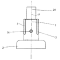
図1〜図4を参照すると、第1の実施例の保持装置は、保持されるべき物体20を収容するための円筒状ホルダと締結手段4とを有する。円筒状ホルダは、一端がベース2に固定されるシリンダ1を具えている。ベース2は磁石であって、鉄ベースの作業面に支持されることができるようになっている。シリンダ1は、120°間隔で相隔て、シリンダ1の長手方向軸線と平行に上端からシリンダ1の下端上部の領域まで延在する3つの長手方向切欠き溝(以下、単に切欠き溝と略記する)3を有する。あるいは、シリンダ1の軸線Aを中心として回転対称に配されるより多くの溝があってよいし、あるいはシリンダ1が溝を全く有しなくてもよい。
【0024】
U字状の締結手段4は、円筒状ホルダを囲んでいる。締結手段4は、クランプ用ボルト7によって連結される2つのアーム5,6を有し、クランプ用ボルト7はアーム6に形成された貫通孔8およびアーム5の雌ねじ孔9に挿入される。クランプ用ボルト7は、軸線Aに対して直交すると共にこの軸線Aに対してオフセットされている。クランプ用ボルト7は、アーム6に隣接する一端につまみ10を有し、つまみ10が回されると、アーム5,6が相互に移動して締結手段4を締め付ける。
【0025】
締結手段4の内面は、円筒状ホルダの切欠き溝3の位置に対応して120°間隔で相隔てた3つの円弧状凹部11,12,13を有する。締結手段4の内面の隣接する円弧状凹部の間の中間部分のみが円筒状ホルダの隣接する切欠き溝3の間の中間部分と接触し、結果として回転対称の力が軸線Aを中心として円筒状ホルダの外周に加えられる。この回転対称の力は、軸線Aに対して直交している。締結手段4の内面は、4つ以上の切欠き溝3を有する円筒状ホルダに対応するように、3つよりも多くの円弧状凹部を有するように形成されることができる。締結手段4の内面から隣接する切欠き溝3の間の円筒状ホルダのそれぞれの位置に等しい力が加えられ、従って、結果として回転対称の力が円筒状ホルダの外周に関して加えられるならば、締結手段4の内面が他の形態を有してもよい。この締結手段4の内面の円筒状ホルダとの当接部分が1つの平面内に配置されていなくてもよい。
【0026】
締結手段4は、アーム5,6の反対位置に形成された締結手段4の貫通孔15を貫通し、隣接する切欠き溝3の間の円筒状ホルダに形成された雌ねじ孔にねじ込まれる止めねじ14により、円筒状ホルダの所定位置に大まかに取り付けられる。締結手段4の貫通孔15は、止めねじ14の頭部が貫通孔15内に位置するように、止めねじ14の頭部の直径よりも大きな直径を有し、従って締結手段4が円筒状ホルダに関して多少動くことを許容する。この構成は、使用する際に締結手段4を迅速に所定位置に保持することを可能とする。締結手段4がベース2に対して自由であって、しかも円筒状ホルダに対して強固に固定されていないので、締結手段4が締め付けられた場合、円筒状ホルダが一方側に押される結果を生ずる可能性がある不均一な力が円筒状ホルダに加えられるような不具合を生じない。上述した止めねじ14に代え、締結手段4が自由であって、これが締め付けられた場合、摩擦によって円筒状ホルダに単に支持されるだけの構造であってもよい。
【0027】
使用時において、保持されるべき物体20は、円筒状ホルダの内部に置かれる。物体20および円筒状ホルダは、作業面上の所望位置に相互に動かされる。次いで、締結手段4は物体20を所望位置に支持するために締め付けられ、円筒状ホルダの磁石ベースがこの保持装置を所定位置に保つ。締結手段4が締め付けられた場合、切欠き溝3は円筒状ホルダが変形して物体を把持できるようにする。
【0028】
この保持装置は、座標位置決め装置(すなわち、欧州特許第508686号に開示されたようなボールバー)を調整するための装置と共に使用する場合に好適である。この場合、物体20は、保持装置によって機械テーブルに支持される球状または一部が球状となった支持部材である。
【0029】
物体20の球状または一部が球状となった部分は、この物体20が保持部材に挿入され、物体20の姿勢を変えることなく締結部材4を締め付けることを可能にする。
【0030】
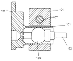
本発明の第2実施例が図5〜図8に示されている。この実施例において、保持装置は光源に対して光ファイバを接続するため使用される。
【0031】
光源は、ハウジング121内に配置され、光ファイバ122の端部が挿入される円筒状ホルダ101に延在する。円筒状ホルダ101の壁は連続しており(すなわち切欠き溝がない)、締結手段104によってこれに力が加えられた場合、これが変形できるように充分薄肉に設定されている。
【0032】
U字形状の締結手段104は、先の実施例のような円筒状ホルダ101の周囲に配置されている。前述のように、締結手段104の内面の3つの部分117,118,119は、円筒状ホルダ101の外周の周りに120°間隔で円筒状ホルダ101と当接し、締結手段104がクランプ用ボルト107によって締め付けられた場合、これらが回転対称の力を円筒状ホルダ101に加えるようになっている。円筒状ホルダ101が薄肉の壁を有するので、締結手段104によって加えられた力は、これが変形することをもたらす。締結手段104の内面と当接する円筒状ホルダ101の部分は、円筒状ホルダ101内に挿入された光ファイバ122の端部に対して押し付けられ、従ってこれをより強力に把持することとなる。締結手段104の内面と直接当接しない円筒状ホルダ101の領域は、締結手段104の凹部111,112,113内に膨出する。従って、凹部111,112,113は円筒状ホルダ101のこの変形部分を受け入れるように充分大きくする必要がある。この実施例において、締結手段104の内面は、円筒状ホルダ101に当接する箇所が120°間隔となって回転対称の力が加えられることを充分可能とするT字形状を形成している。
【0033】
使用時において、光ファイバ122の端部が円筒状ホルダ101に挿入され、これがハウジング121内の光源と接続されるまでその位置が調整される。光ファイバ122は、締結手段104を締め付けることにより、その位置に保持される。光ファイバ122の末端部は、これがその箇所での最大径の球状または一部が球状となった球状部123を含むように形成されている。光ファイバ122の角度が円筒状ホルダ101に対して調整されても、この球状または一部が球状となった球状部123は、円筒状ホルダ101の内面に対して変わらない表面を常に与える。従って、光ファイバ122の端部は、3つの軸線(上下,前後,左右)すべてを中心として角度が調整可能である。締結手段104が締め付けられた場合、回転対称の力が円筒状ホルダ101に加えられ、締結手段104は光ファイバ122の望まざる移動を排除する。
【0034】
光ファイバ122がz軸(すなわち、光ファイバ122の長手方向軸線と平行である)に配置された場合、x軸およびy軸に光ファイバ122の位置を調整するため、これを手動で操作することができる。これは、ハウジング121の反対側に位置する光ファイバ122の端部を延在させることにより可能であり、これは、球状部123を中心としてピボット回転する機械的レバーとして作用するようになっている。
【0035】
塵埃などの混入を防止するため、光ファイバの位置を調整して締結手段104を締め付けた後、この締結手段104の凹部111,112,113にシール剤を充填するようにしてもよい。
【0036】
この保持装置は、複数種の光源、例えばHe−Neレーザーおよびダイオードレーザーに対して光ファイバ122を接続するために用いられることができる。これはまた、干渉計または結合器の如き他の装置に光ファイバ122を接続する際にも用いて好適である。
【0037】
光ファイバ122を光源に接続することに加え、この保持装置はプリズムまたは反射鏡の如き他の光学素子に接続するために用いることができる。例えば、この保持装置は、周知の距離を隔てて配置されるファブリ−ペロー干渉計の2つの半鍍銀ガラス板と接続するために用いることができる。第1の半鍍銀ガラス板はハウジング121内に配置され、第2の半鍍銀ガラス板は球状部123内に配置されることができる。
【0038】
【発明の効果】
本発明の保持装置によると、締結手段がホルダに対して柔軟に装着され、締め付けられた場合にホルダの外周を囲む回転対称位置に力が加えられ、次いでホルダが物体に対し回転対称の締結力を伝達するため、締結手段が保持されるべき物体に対して回転対称の力のみを加えることができ、締結時における物体の移動を阻止することが可能となった。
【0039】
また、締結手段を保持装置のベースに装着していないため、非対称な力に関する他の原因も排除することができる。
【図面の簡単な説明】
【図1】円筒状ホルダの側面図である。
【図2】締結手段を取り付けた円筒状ホルダの破断平面図である。
【図3】締結手段を取り付けた円筒状ホルダの側面図である。
【図4】締結手段を取り付けた円筒状ホルダの破断側面図である。
【図5】ファイバ接続用保持装置の破断側面である。
【図6】締結手段を示すファイバ接続用保持装置の端面図である。
【図7】ファイバ接続用保持装置の側面図である。
【図8】ファイバ接続用保持装置の斜視図である。
【符号の説明】
A シリンダの軸線
1 シリンダ
2 ベース
3 長手方向切欠き溝
4 締結手段
5 アーム
6 アーム
7 クランプ用ボルト
8 貫通孔
9 雌ねじ孔
10 つまみ
11〜13 円弧状凹部
14 止めねじ
15 貫通孔
20 物体
101 円筒状ホルダ
104 締結手段
107 クランプ用ボルト
111〜113 凹部
117〜119 締結手段の内面の当接部
121 ハウジング
122 光ファイバ
123 球状部[0001]
BACKGROUND OF THE INVENTION
The present invention relates to a holding device suitable for supporting an object at a desired position.
[0002]
[Prior art]
Such holding devices generally comprise fastening means having a pair of jaws surrounding a cylindrical gap. The object can be held in the cylindrical gap by tightening fastening bolts that are screwed with both jaws of the fastening means. Such a device is disclosed in EP 508686.
[0003]
[Problems to be solved by the invention]
The above-mentioned holding device has the disadvantage that the object to be held is pushed slightly to one side when the fastening means is tightened. This movement of the object is brought about by an asymmetric force applied to the object by fastening means which act to “pinch” the object. When the fastening means is firmly fixed to the base of the holding device, the tendency of the object to move by the tightening operation of the fastening means is increased.
[0004]
OBJECT OF THE INVENTION
An object of the present invention is to provide a holding device that eliminates the movement of an object during fastening by applying only a symmetric force to the object to be fastened by the fastening means. Further, by not attaching the fastening means to the base of the holding device, further causes relating to asymmetric forces are eliminated.
[0005]
[Means for Solving the Problems]
A preferred embodiment of the present invention is a holding device for detachably holding an object having at least a partial spherical portion in a fixed position, a holder into which at least a partial spherical portion is inserted, and a holder for the holder. Fastening means for enclosing the outer periphery, the fastening means being adapted to adjust the angle about at least one axis in the holder until the fastening means fastens the object fixed at a predetermined position. , if the fastening means is tightened, is force added to the rotation symmetry position location surrounding the outer periphery of the holder, then the holder is adapted to transmit the fastening force of the rotation symmetrical with respect to the object.
[0006]
DETAILED DESCRIPTION OF THE INVENTION
The holder may have a deformable cylindrical shape, and the holder may be deformed when the fastening means is tightened.
[0007]
The holder can be cylindrical.
[0008]
The force applied to the outer periphery of the holder may be perpendicular to the longitudinal axis of the holder.
[0009]
It is preferable that the fastening means is flexible with respect to the holder, that is, attached with a certain amount of play.
[0010]
The holder has a plurality of notches, and in particular, three can be provided rotationally symmetrically about the longitudinal axis of the holder.
[0011]
The fastening means has an inner surface having a plurality of recesses with the longitudinal axis of the holder as the center, and a portion of the inner surface located between these adjacent recesses contacts the holder, and the contact portion of the inner surface with the holder is It may be formed to be rotationally symmetric about the longitudinal axis of the holder.
[0012]
The holder may have three notch grooves, and the abutting part of the inner surface of the fastening means with the holder may be arranged so as to abut against a part between adjacent notch grooves of the holder.
[0013]
After tightening the fastening means, it is possible to fill the concave portion located between the contact portion of the inner surface with the holder and the sealing agent.
[0014]
The fastening means and the holder can be brought into contact with each other at three locations.
[0015]
The holder can be provided with a magnet base.
[0016]
The fastening means may have a U-shaped part surrounding the outer periphery of the holder, and the two arms of the U-shaped part may have a structure that can be pulled toward each other in order to fasten the fastening means.
[0017]
The fastening means may be fastened by a screw member having a rotation axis perpendicular to the longitudinal axis of the holder.
[0019]
The object may be adjustable in a straight line parallel to the longitudinal axis of the holder.
[0020]
The object may have one end of an optical fiber.
[0021]
The holding device may be a ballbar device fastener.
[0022]
【Example】
Embodiments of the holding device according to the present invention will be described in detail with reference to FIGS. 1 to 8, but the present invention is not limited to these embodiments, and further combinations thereof are described in the claims. Any change or modification included in the concept of the present invention can be made, and can of course be applied to any other technique belonging to the spirit of the present invention.
[0023]
1 to 4, the holding device according to the first embodiment includes a cylindrical holder for holding an
[0024]
The U-shaped fastening means 4 surrounds the cylindrical holder. The fastening means 4 has two
[0025]
The inner surface of the fastening means 4 has three
[0026]
The fastening means 4 passes through a through
[0027]
In use, the
[0028]
This holding device is suitable for use with a device for adjusting a coordinate positioning device (ie a ball bar as disclosed in EP 508686). In this case, the
[0029]
The spherical portion of the
[0030]
A second embodiment of the present invention is shown in FIGS. In this embodiment, the holding device is used to connect the optical fiber to the light source.
[0031]
The light source is disposed in the
[0032]
The U-shaped fastening means 104 is arranged around the
[0033]
In use, the end of the
[0034]
If the
[0035]
In order to prevent dust and the like from being mixed, after the fastening means 104 is tightened by adjusting the position of the optical fiber, the
[0036]
The holding device can be used to connect the
[0037]
In addition to connecting the
[0038]
【Effect of the invention】
According to the holding device of the present invention, the fastening means is flexibly attached to the holder, a force is applied to the rotation symmetry position location surrounding the outer periphery of the holder when tightened, then the holder is rotationally symmetrical with respect to the object Since the fastening force is transmitted, only a rotationally symmetric force can be applied to the object to which the fastening means is to be held, and the movement of the object at the time of fastening can be prevented.
[0039]
Further, since the fastening means is not attached to the base of the holding device, other causes relating to the asymmetric force can be eliminated.
[Brief description of the drawings]
FIG. 1 is a side view of a cylindrical holder.
FIG. 2 is a cutaway plan view of a cylindrical holder to which fastening means is attached.
FIG. 3 is a side view of a cylindrical holder with fastening means attached thereto.
FIG. 4 is a cutaway side view of a cylindrical holder with fastening means attached thereto.
FIG. 5 is a broken side view of a fiber connection holding device.
FIG. 6 is an end view of the fiber connection holding device showing the fastening means.
FIG. 7 is a side view of the fiber connection holding device.
FIG. 8 is a perspective view of a fiber connection holding device.
[Explanation of symbols]
A
Claims (17)
前記少なくとも部分的な球状部(123)が挿入されるホルダ(1,101)と、
このホルダの外周を囲む締結手段(4,104)であって、この締結手段が所定位置に固定される前記物体(20,122)を締め付けるまで、前記物体(20,122)が前記ホルダ(1,101)内で少なくとも1つの軸線を中心として角度を調整できるようになっている締結手段(4,104)と
を具え、前記締結手段(4,104)が締め付けられた場合、前記ホルダ(1,101)の外周の回転対称位置に力が加えられ、次いで前記ホルダが物体(20,122)に対し回転対称の締結力を伝達することを特徴とする保持装置。A holding device for removably holding an object (20, 122) having at least a partial spherical portion (123) in a fixed position,
A holder (1, 101) into which the at least partial spherical portion (123) is inserted;
Fastening means (4, 104) surrounding the outer periphery of the holder, and the object (20, 122) is held in the holder (1) until the fastening means fastens the object (20, 122) fixed at a predetermined position. , 101) and fastening means (4, 104) adapted to adjust the angle around at least one axis, and when the fastening means (4, 104) is tightened, the holder (1 , 101) rotational symmetry position location of the outer force is applied to the, then holding device, characterized in that the holder for transmitting the clamping force of the rotational symmetry with respect to the object (20,122).
Applications Claiming Priority (2)
| Application Number | Priority Date | Filing Date | Title |
|---|---|---|---|
| GBGB0023849.3A GB0023849D0 (en) | 2000-09-29 | 2000-09-29 | Retaining device |
| GB0023849.3 | 2000-09-29 |
Publications (3)
| Publication Number | Publication Date |
|---|---|
| JP2002195220A JP2002195220A (en) | 2002-07-10 |
| JP2002195220A5 JP2002195220A5 (en) | 2008-11-13 |
| JP4942887B2 true JP4942887B2 (en) | 2012-05-30 |
Family
ID=9900342
Family Applications (1)
| Application Number | Title | Priority Date | Filing Date |
|---|---|---|---|
| JP2001301922A Expired - Fee Related JP4942887B2 (en) | 2000-09-29 | 2001-09-28 | Holding device |
Country Status (6)
| Country | Link |
|---|---|
| US (1) | US6776551B2 (en) |
| EP (1) | EP1193402B1 (en) |
| JP (1) | JP4942887B2 (en) |
| AT (1) | ATE289658T1 (en) |
| DE (1) | DE60109004T2 (en) |
| GB (1) | GB0023849D0 (en) |
Families Citing this family (20)
| Publication number | Priority date | Publication date | Assignee | Title |
|---|---|---|---|---|
| DE20215754U1 (en) * | 2002-10-10 | 2004-02-26 | Dr. Johannes Heidenhain Gmbh | Clamping device, comprising clamping sleeve enveloping shaft of clamped object and provided with small bore serving as pressure compensating area |
| GB0223685D0 (en) * | 2002-10-11 | 2002-11-20 | Preston David | Slidable and rotatable clamp arrangements |
| DE102005031839C5 (en) * | 2005-07-06 | 2015-05-07 | Wittenstein Ag | Clamping element for connecting a motor shaft with a gearbox via a hub |
| US7478970B2 (en) * | 2006-01-03 | 2009-01-20 | Wimberley David L | Shaft clamping mechanism |
| US7609020B2 (en) * | 2006-07-11 | 2009-10-27 | Delaware Capital Formation, Inc. | Geometric end effector system |
| TWI304715B (en) * | 2006-07-14 | 2008-12-21 | Ama Precision Inc | Connecting structure and method thereof |
| US20090158884A1 (en) * | 2007-12-20 | 2009-06-25 | Ming Hsing Leather Co., Ltd. | Positioning assembly for gripping tube of handlebar |
| JP5297890B2 (en) * | 2008-12-03 | 2013-09-25 | 本田技研工業株式会社 | Pipe handle holding mechanism |
| US8628318B1 (en) * | 2010-03-03 | 2014-01-14 | Exceptional Ip Holdings, Llc | Apparatus and methods for tool(s) to work on building surface(s) |
| DE102011013887B4 (en) * | 2011-03-07 | 2017-06-29 | Stöber Antriebstechnik GmbH & Co. KG | Clamping coupling for non-rotatable connection of two rotating parts, preferably shaft and hub |
| CN103842868B (en) * | 2011-06-16 | 2016-03-23 | 飞尔康有限公司 | The joints of optical fibre |
| KR101480230B1 (en) | 2013-06-12 | 2015-01-21 | 경북대학교 산학협력단 | Center mounting apparatus and ballbar system having the same |
| KR101480228B1 (en) | 2013-06-12 | 2015-01-21 | 경북대학교 산학협력단 | Center mounting apparatus and ballbar system having the same |
| CN103758160B (en) * | 2014-01-09 | 2015-06-24 | 华中科技大学 | Super deep underground diaphragm wall deformation automatic real-time monitoring device and operating method thereof |
| CN104676120A (en) * | 2015-03-11 | 2015-06-03 | 国家电网公司 | Power cable spacing clamp |
| US10618394B2 (en) * | 2017-04-20 | 2020-04-14 | Bestop, Inc. | Removable door surround for a folding soft top |
| CN107086527A (en) * | 2017-05-09 | 2017-08-22 | 嘉兴恒创电力设计研究院有限公司嘉善分公司 | A kind of anchor ear for electric power porcelain vase |
| DE102017122385B3 (en) | 2017-09-27 | 2018-12-13 | Physik Instrumente (Pi) Gmbh & Co. Kg | Fiber holder system |
| US10928593B2 (en) * | 2018-10-03 | 2021-02-23 | Elenion Technologies, Llc | Fiber holder |
| US11644053B2 (en) * | 2019-11-26 | 2023-05-09 | Medos International Sarl | Instrument coupling interfaces and related methods |
Family Cites Families (20)
| Publication number | Priority date | Publication date | Assignee | Title |
|---|---|---|---|---|
| US1806687A (en) * | 1931-05-26 | Charles w | ||
| US2241042A (en) * | 1939-12-01 | 1941-05-06 | Winthrop T Scarritt | Clamping device |
| US2338343A (en) * | 1941-05-26 | 1944-01-04 | Maire Georges | Watch crystal assembly tool |
| US3354672A (en) * | 1965-03-22 | 1967-11-28 | Crompton & Knowles Malimo Inc | Connecting means |
| CA934777A (en) * | 1972-05-05 | 1973-10-02 | M. Tulk George | Vise |
| US3776649A (en) * | 1972-08-23 | 1973-12-04 | Barnes Eng Co | Locking ball joint |
| US3946467A (en) * | 1974-12-09 | 1976-03-30 | Northern Electric Company, Limited | Clamp for an optical fibre |
| FR2388373A1 (en) * | 1977-04-19 | 1978-11-17 | Debucourt Precision | Seats for joints of comparator support extension arms - to obtain compact, firm joints, are pref. of Teflon |
| JPS58150608A (en) * | 1982-02-27 | 1983-09-07 | Akai Isao | Antipollution system for water region |
| JPS58169649A (en) * | 1982-03-25 | 1983-10-06 | Fujitsu Ltd | Control system of storage device |
| DE3408210C1 (en) * | 1984-03-07 | 1985-06-20 | Maschinenfabrik Ernst Thielenhaus GmbH, 5600 Wuppertal | Device for clamping workpieces during fine grinding |
| JPH02103509A (en) * | 1988-10-13 | 1990-04-16 | Asahi Chem Ind Co Ltd | Plastic optical fiber cord |
| JP2533477Y2 (en) * | 1989-07-31 | 1997-04-23 | 株式会社リコー | Transfer device |
| GB2261256B (en) * | 1989-12-06 | 1993-08-11 | Oetiker Hans Maschinen | Improved hose clamp |
| EP0508686B1 (en) | 1991-04-12 | 1996-06-05 | Renishaw Transducer Systems Limited | Calibration device for machine |
| FR2701070B1 (en) * | 1993-02-01 | 1995-12-22 | Neuhaus Sa Jean | CLAMP FOR FIXING ON A SUBSTANTIALLY CIRCULAR SECTION ELEMENT. |
| DE19521755C1 (en) * | 1995-06-14 | 1996-10-02 | Schunk Fritz Gmbh | System repeatedly connecting two components |
| AUPO663897A0 (en) * | 1997-05-06 | 1997-05-29 | Krautloher, Alois | Orientation device |
| US6116845A (en) * | 1998-03-19 | 2000-09-12 | Atlas Technologies, Inc. | Apparatus for supporting a workpiece for transfer |
| DE19907181B4 (en) * | 1999-02-19 | 2004-02-19 | Neugart Gmbh & Co. | Connection of a slotted hollow shaft, hollow shaft or sleeve with an engaging counterpart |
-
2000
- 2000-09-29 GB GBGB0023849.3A patent/GB0023849D0/en not_active Ceased
-
2001
- 2001-09-20 DE DE60109004T patent/DE60109004T2/en not_active Expired - Lifetime
- 2001-09-20 AT AT01308026T patent/ATE289658T1/en not_active IP Right Cessation
- 2001-09-20 US US09/956,027 patent/US6776551B2/en not_active Expired - Lifetime
- 2001-09-20 EP EP01308026A patent/EP1193402B1/en not_active Expired - Lifetime
- 2001-09-28 JP JP2001301922A patent/JP4942887B2/en not_active Expired - Fee Related
Also Published As
| Publication number | Publication date |
|---|---|
| US20020040953A1 (en) | 2002-04-11 |
| GB0023849D0 (en) | 2000-11-15 |
| ATE289658T1 (en) | 2005-03-15 |
| JP2002195220A (en) | 2002-07-10 |
| US6776551B2 (en) | 2004-08-17 |
| DE60109004T2 (en) | 2006-03-02 |
| DE60109004D1 (en) | 2005-03-31 |
| EP1193402A1 (en) | 2002-04-03 |
| EP1193402B1 (en) | 2005-02-23 |
Similar Documents
| Publication | Publication Date | Title |
|---|---|---|
| JP4942887B2 (en) | Holding device | |
| EP1267742B1 (en) | Surgical instrument support | |
| JP2871620B2 (en) | Bone fixation device | |
| US6179846B1 (en) | Surgical head clamping device | |
| JPH05184593A (en) | Clamp coupling device | |
| SG80683A1 (en) | An apparatus for clamping a work piece | |
| BR9402998A (en) | Straight or angled chuck with a detachable clamping device for a tool, in particular for medical purposes and chuck tool | |
| JP2004097706A (en) | Rod connector | |
| JPS6331653A (en) | Clamp jig | |
| US6695350B2 (en) | Rocker arm mechanism for clamping an adjustable steering column | |
| KR950703424A (en) | QUICK-CHANGE TOOL HOLDER WITH ADJUSTMENT MECHANISM | |
| JP2006334672A (en) | Clamp type hand tool | |
| US5411235A (en) | Fixture for angularly aligning an optical device | |
| JPS606909A (en) | Adjustment type optical connector | |
| JPH02239854A (en) | Apparatus supporter for operation | |
| JPH0424166Y2 (en) | ||
| US6397708B1 (en) | Screwdriver grip | |
| JP3234972B2 (en) | Flexible fixing device for various video equipment such as camera and video | |
| JPH10138056A (en) | Bolt tightening/loosening device | |
| EP0355079A1 (en) | Fastening implement | |
| JPS6246896Y2 (en) | ||
| JPH09238891A (en) | Support device of endoscope | |
| JP2896554B2 (en) | Collet holder | |
| JP2010017448A (en) | Connector | |
| JPH1190839A (en) | Clamp device |
Legal Events
| Date | Code | Title | Description |
|---|---|---|---|
| A521 | Request for written amendment filed |
Free format text: JAPANESE INTERMEDIATE CODE: A523 Effective date: 20080926 |
|
| A621 | Written request for application examination |
Free format text: JAPANESE INTERMEDIATE CODE: A621 Effective date: 20080926 |
|
| RD04 | Notification of resignation of power of attorney |
Free format text: JAPANESE INTERMEDIATE CODE: A7424 Effective date: 20080926 |
|
| A977 | Report on retrieval |
Free format text: JAPANESE INTERMEDIATE CODE: A971007 Effective date: 20110725 |
|
| A131 | Notification of reasons for refusal |
Free format text: JAPANESE INTERMEDIATE CODE: A131 Effective date: 20110805 |
|
| A521 | Request for written amendment filed |
Free format text: JAPANESE INTERMEDIATE CODE: A523 Effective date: 20111031 |
|
| TRDD | Decision of grant or rejection written | ||
| A01 | Written decision to grant a patent or to grant a registration (utility model) |
Free format text: JAPANESE INTERMEDIATE CODE: A01 Effective date: 20120217 |
|
| A01 | Written decision to grant a patent or to grant a registration (utility model) |
Free format text: JAPANESE INTERMEDIATE CODE: A01 |
|
| A61 | First payment of annual fees (during grant procedure) |
Free format text: JAPANESE INTERMEDIATE CODE: A61 Effective date: 20120229 |
|
| R150 | Certificate of patent or registration of utility model |
Free format text: JAPANESE INTERMEDIATE CODE: R150 Ref document number: 4942887 Country of ref document: JP Free format text: JAPANESE INTERMEDIATE CODE: R150 |
|
| FPAY | Renewal fee payment (event date is renewal date of database) |
Free format text: PAYMENT UNTIL: 20150309 Year of fee payment: 3 |
|
| R250 | Receipt of annual fees |
Free format text: JAPANESE INTERMEDIATE CODE: R250 |
|
| R250 | Receipt of annual fees |
Free format text: JAPANESE INTERMEDIATE CODE: R250 |
|
| R250 | Receipt of annual fees |
Free format text: JAPANESE INTERMEDIATE CODE: R250 |
|
| R250 | Receipt of annual fees |
Free format text: JAPANESE INTERMEDIATE CODE: R250 |
|
| R250 | Receipt of annual fees |
Free format text: JAPANESE INTERMEDIATE CODE: R250 |
|
| R250 | Receipt of annual fees |
Free format text: JAPANESE INTERMEDIATE CODE: R250 |
|
| LAPS | Cancellation because of no payment of annual fees |