JP4940984B2 - Control device for vehicle drive device - Google Patents
Control device for vehicle drive device Download PDFInfo
- Publication number
- JP4940984B2 JP4940984B2 JP2007034157A JP2007034157A JP4940984B2 JP 4940984 B2 JP4940984 B2 JP 4940984B2 JP 2007034157 A JP2007034157 A JP 2007034157A JP 2007034157 A JP2007034157 A JP 2007034157A JP 4940984 B2 JP4940984 B2 JP 4940984B2
- Authority
- JP
- Japan
- Prior art keywords
- differential
- speed
- stepped
- gear
- shift
- Prior art date
- Legal status (The legal status is an assumption and is not a legal conclusion. Google has not performed a legal analysis and makes no representation as to the accuracy of the status listed.)
- Active
Links
Images


Classifications
-
- B—PERFORMING OPERATIONS; TRANSPORTING
- B60—VEHICLES IN GENERAL
- B60W—CONJOINT CONTROL OF VEHICLE SUB-UNITS OF DIFFERENT TYPE OR DIFFERENT FUNCTION; CONTROL SYSTEMS SPECIALLY ADAPTED FOR HYBRID VEHICLES; ROAD VEHICLE DRIVE CONTROL SYSTEMS FOR PURPOSES NOT RELATED TO THE CONTROL OF A PARTICULAR SUB-UNIT
- B60W20/00—Control systems specially adapted for hybrid vehicles
- B60W20/30—Control strategies involving selection of transmission gear ratio
-
- B—PERFORMING OPERATIONS; TRANSPORTING
- B60—VEHICLES IN GENERAL
- B60K—ARRANGEMENT OR MOUNTING OF PROPULSION UNITS OR OF TRANSMISSIONS IN VEHICLES; ARRANGEMENT OR MOUNTING OF PLURAL DIVERSE PRIME-MOVERS IN VEHICLES; AUXILIARY DRIVES FOR VEHICLES; INSTRUMENTATION OR DASHBOARDS FOR VEHICLES; ARRANGEMENTS IN CONNECTION WITH COOLING, AIR INTAKE, GAS EXHAUST OR FUEL SUPPLY OF PROPULSION UNITS IN VEHICLES
- B60K6/00—Arrangement or mounting of plural diverse prime-movers for mutual or common propulsion, e.g. hybrid propulsion systems comprising electric motors and internal combustion engines ; Control systems therefor, i.e. systems controlling two or more prime movers, or controlling one of these prime movers and any of the transmission, drive or drive units Informative references: mechanical gearings with secondary electric drive F16H3/72; arrangements for handling mechanical energy structurally associated with the dynamo-electric machine H02K7/00; machines comprising structurally interrelated motor and generator parts H02K51/00; dynamo-electric machines not otherwise provided for in H02K see H02K99/00
- B60K6/20—Arrangement or mounting of plural diverse prime-movers for mutual or common propulsion, e.g. hybrid propulsion systems comprising electric motors and internal combustion engines ; Control systems therefor, i.e. systems controlling two or more prime movers, or controlling one of these prime movers and any of the transmission, drive or drive units Informative references: mechanical gearings with secondary electric drive F16H3/72; arrangements for handling mechanical energy structurally associated with the dynamo-electric machine H02K7/00; machines comprising structurally interrelated motor and generator parts H02K51/00; dynamo-electric machines not otherwise provided for in H02K see H02K99/00 the prime-movers consisting of electric motors and internal combustion engines, e.g. HEVs
- B60K6/22—Arrangement or mounting of plural diverse prime-movers for mutual or common propulsion, e.g. hybrid propulsion systems comprising electric motors and internal combustion engines ; Control systems therefor, i.e. systems controlling two or more prime movers, or controlling one of these prime movers and any of the transmission, drive or drive units Informative references: mechanical gearings with secondary electric drive F16H3/72; arrangements for handling mechanical energy structurally associated with the dynamo-electric machine H02K7/00; machines comprising structurally interrelated motor and generator parts H02K51/00; dynamo-electric machines not otherwise provided for in H02K see H02K99/00 the prime-movers consisting of electric motors and internal combustion engines, e.g. HEVs characterised by apparatus, components or means specially adapted for HEVs
- B60K6/36—Arrangement or mounting of plural diverse prime-movers for mutual or common propulsion, e.g. hybrid propulsion systems comprising electric motors and internal combustion engines ; Control systems therefor, i.e. systems controlling two or more prime movers, or controlling one of these prime movers and any of the transmission, drive or drive units Informative references: mechanical gearings with secondary electric drive F16H3/72; arrangements for handling mechanical energy structurally associated with the dynamo-electric machine H02K7/00; machines comprising structurally interrelated motor and generator parts H02K51/00; dynamo-electric machines not otherwise provided for in H02K see H02K99/00 the prime-movers consisting of electric motors and internal combustion engines, e.g. HEVs characterised by apparatus, components or means specially adapted for HEVs characterised by the transmission gearings
- B60K6/365—Arrangement or mounting of plural diverse prime-movers for mutual or common propulsion, e.g. hybrid propulsion systems comprising electric motors and internal combustion engines ; Control systems therefor, i.e. systems controlling two or more prime movers, or controlling one of these prime movers and any of the transmission, drive or drive units Informative references: mechanical gearings with secondary electric drive F16H3/72; arrangements for handling mechanical energy structurally associated with the dynamo-electric machine H02K7/00; machines comprising structurally interrelated motor and generator parts H02K51/00; dynamo-electric machines not otherwise provided for in H02K see H02K99/00 the prime-movers consisting of electric motors and internal combustion engines, e.g. HEVs characterised by apparatus, components or means specially adapted for HEVs characterised by the transmission gearings with the gears having orbital motion
-
- B—PERFORMING OPERATIONS; TRANSPORTING
- B60—VEHICLES IN GENERAL
- B60K—ARRANGEMENT OR MOUNTING OF PROPULSION UNITS OR OF TRANSMISSIONS IN VEHICLES; ARRANGEMENT OR MOUNTING OF PLURAL DIVERSE PRIME-MOVERS IN VEHICLES; AUXILIARY DRIVES FOR VEHICLES; INSTRUMENTATION OR DASHBOARDS FOR VEHICLES; ARRANGEMENTS IN CONNECTION WITH COOLING, AIR INTAKE, GAS EXHAUST OR FUEL SUPPLY OF PROPULSION UNITS IN VEHICLES
- B60K6/00—Arrangement or mounting of plural diverse prime-movers for mutual or common propulsion, e.g. hybrid propulsion systems comprising electric motors and internal combustion engines ; Control systems therefor, i.e. systems controlling two or more prime movers, or controlling one of these prime movers and any of the transmission, drive or drive units Informative references: mechanical gearings with secondary electric drive F16H3/72; arrangements for handling mechanical energy structurally associated with the dynamo-electric machine H02K7/00; machines comprising structurally interrelated motor and generator parts H02K51/00; dynamo-electric machines not otherwise provided for in H02K see H02K99/00
- B60K6/20—Arrangement or mounting of plural diverse prime-movers for mutual or common propulsion, e.g. hybrid propulsion systems comprising electric motors and internal combustion engines ; Control systems therefor, i.e. systems controlling two or more prime movers, or controlling one of these prime movers and any of the transmission, drive or drive units Informative references: mechanical gearings with secondary electric drive F16H3/72; arrangements for handling mechanical energy structurally associated with the dynamo-electric machine H02K7/00; machines comprising structurally interrelated motor and generator parts H02K51/00; dynamo-electric machines not otherwise provided for in H02K see H02K99/00 the prime-movers consisting of electric motors and internal combustion engines, e.g. HEVs
- B60K6/22—Arrangement or mounting of plural diverse prime-movers for mutual or common propulsion, e.g. hybrid propulsion systems comprising electric motors and internal combustion engines ; Control systems therefor, i.e. systems controlling two or more prime movers, or controlling one of these prime movers and any of the transmission, drive or drive units Informative references: mechanical gearings with secondary electric drive F16H3/72; arrangements for handling mechanical energy structurally associated with the dynamo-electric machine H02K7/00; machines comprising structurally interrelated motor and generator parts H02K51/00; dynamo-electric machines not otherwise provided for in H02K see H02K99/00 the prime-movers consisting of electric motors and internal combustion engines, e.g. HEVs characterised by apparatus, components or means specially adapted for HEVs
- B60K6/40—Arrangement or mounting of plural diverse prime-movers for mutual or common propulsion, e.g. hybrid propulsion systems comprising electric motors and internal combustion engines ; Control systems therefor, i.e. systems controlling two or more prime movers, or controlling one of these prime movers and any of the transmission, drive or drive units Informative references: mechanical gearings with secondary electric drive F16H3/72; arrangements for handling mechanical energy structurally associated with the dynamo-electric machine H02K7/00; machines comprising structurally interrelated motor and generator parts H02K51/00; dynamo-electric machines not otherwise provided for in H02K see H02K99/00 the prime-movers consisting of electric motors and internal combustion engines, e.g. HEVs characterised by apparatus, components or means specially adapted for HEVs characterised by the assembly or relative disposition of components
-
- B—PERFORMING OPERATIONS; TRANSPORTING
- B60—VEHICLES IN GENERAL
- B60K—ARRANGEMENT OR MOUNTING OF PROPULSION UNITS OR OF TRANSMISSIONS IN VEHICLES; ARRANGEMENT OR MOUNTING OF PLURAL DIVERSE PRIME-MOVERS IN VEHICLES; AUXILIARY DRIVES FOR VEHICLES; INSTRUMENTATION OR DASHBOARDS FOR VEHICLES; ARRANGEMENTS IN CONNECTION WITH COOLING, AIR INTAKE, GAS EXHAUST OR FUEL SUPPLY OF PROPULSION UNITS IN VEHICLES
- B60K6/00—Arrangement or mounting of plural diverse prime-movers for mutual or common propulsion, e.g. hybrid propulsion systems comprising electric motors and internal combustion engines ; Control systems therefor, i.e. systems controlling two or more prime movers, or controlling one of these prime movers and any of the transmission, drive or drive units Informative references: mechanical gearings with secondary electric drive F16H3/72; arrangements for handling mechanical energy structurally associated with the dynamo-electric machine H02K7/00; machines comprising structurally interrelated motor and generator parts H02K51/00; dynamo-electric machines not otherwise provided for in H02K see H02K99/00
- B60K6/20—Arrangement or mounting of plural diverse prime-movers for mutual or common propulsion, e.g. hybrid propulsion systems comprising electric motors and internal combustion engines ; Control systems therefor, i.e. systems controlling two or more prime movers, or controlling one of these prime movers and any of the transmission, drive or drive units Informative references: mechanical gearings with secondary electric drive F16H3/72; arrangements for handling mechanical energy structurally associated with the dynamo-electric machine H02K7/00; machines comprising structurally interrelated motor and generator parts H02K51/00; dynamo-electric machines not otherwise provided for in H02K see H02K99/00 the prime-movers consisting of electric motors and internal combustion engines, e.g. HEVs
- B60K6/42—Arrangement or mounting of plural diverse prime-movers for mutual or common propulsion, e.g. hybrid propulsion systems comprising electric motors and internal combustion engines ; Control systems therefor, i.e. systems controlling two or more prime movers, or controlling one of these prime movers and any of the transmission, drive or drive units Informative references: mechanical gearings with secondary electric drive F16H3/72; arrangements for handling mechanical energy structurally associated with the dynamo-electric machine H02K7/00; machines comprising structurally interrelated motor and generator parts H02K51/00; dynamo-electric machines not otherwise provided for in H02K see H02K99/00 the prime-movers consisting of electric motors and internal combustion engines, e.g. HEVs characterised by the architecture of the hybrid electric vehicle
- B60K6/44—Series-parallel type
- B60K6/445—Differential gearing distribution type
-
- B—PERFORMING OPERATIONS; TRANSPORTING
- B60—VEHICLES IN GENERAL
- B60K—ARRANGEMENT OR MOUNTING OF PROPULSION UNITS OR OF TRANSMISSIONS IN VEHICLES; ARRANGEMENT OR MOUNTING OF PLURAL DIVERSE PRIME-MOVERS IN VEHICLES; AUXILIARY DRIVES FOR VEHICLES; INSTRUMENTATION OR DASHBOARDS FOR VEHICLES; ARRANGEMENTS IN CONNECTION WITH COOLING, AIR INTAKE, GAS EXHAUST OR FUEL SUPPLY OF PROPULSION UNITS IN VEHICLES
- B60K6/00—Arrangement or mounting of plural diverse prime-movers for mutual or common propulsion, e.g. hybrid propulsion systems comprising electric motors and internal combustion engines ; Control systems therefor, i.e. systems controlling two or more prime movers, or controlling one of these prime movers and any of the transmission, drive or drive units Informative references: mechanical gearings with secondary electric drive F16H3/72; arrangements for handling mechanical energy structurally associated with the dynamo-electric machine H02K7/00; machines comprising structurally interrelated motor and generator parts H02K51/00; dynamo-electric machines not otherwise provided for in H02K see H02K99/00
- B60K6/20—Arrangement or mounting of plural diverse prime-movers for mutual or common propulsion, e.g. hybrid propulsion systems comprising electric motors and internal combustion engines ; Control systems therefor, i.e. systems controlling two or more prime movers, or controlling one of these prime movers and any of the transmission, drive or drive units Informative references: mechanical gearings with secondary electric drive F16H3/72; arrangements for handling mechanical energy structurally associated with the dynamo-electric machine H02K7/00; machines comprising structurally interrelated motor and generator parts H02K51/00; dynamo-electric machines not otherwise provided for in H02K see H02K99/00 the prime-movers consisting of electric motors and internal combustion engines, e.g. HEVs
- B60K6/50—Architecture of the driveline characterised by arrangement or kind of transmission units
- B60K6/54—Transmission for changing ratio
- B60K6/547—Transmission for changing ratio the transmission being a stepped gearing
-
- B—PERFORMING OPERATIONS; TRANSPORTING
- B60—VEHICLES IN GENERAL
- B60W—CONJOINT CONTROL OF VEHICLE SUB-UNITS OF DIFFERENT TYPE OR DIFFERENT FUNCTION; CONTROL SYSTEMS SPECIALLY ADAPTED FOR HYBRID VEHICLES; ROAD VEHICLE DRIVE CONTROL SYSTEMS FOR PURPOSES NOT RELATED TO THE CONTROL OF A PARTICULAR SUB-UNIT
- B60W10/00—Conjoint control of vehicle sub-units of different type or different function
- B60W10/04—Conjoint control of vehicle sub-units of different type or different function including control of propulsion units
- B60W10/06—Conjoint control of vehicle sub-units of different type or different function including control of propulsion units including control of combustion engines
-
- B—PERFORMING OPERATIONS; TRANSPORTING
- B60—VEHICLES IN GENERAL
- B60W—CONJOINT CONTROL OF VEHICLE SUB-UNITS OF DIFFERENT TYPE OR DIFFERENT FUNCTION; CONTROL SYSTEMS SPECIALLY ADAPTED FOR HYBRID VEHICLES; ROAD VEHICLE DRIVE CONTROL SYSTEMS FOR PURPOSES NOT RELATED TO THE CONTROL OF A PARTICULAR SUB-UNIT
- B60W10/00—Conjoint control of vehicle sub-units of different type or different function
- B60W10/04—Conjoint control of vehicle sub-units of different type or different function including control of propulsion units
- B60W10/08—Conjoint control of vehicle sub-units of different type or different function including control of propulsion units including control of electric propulsion units, e.g. motors or generators
-
- B—PERFORMING OPERATIONS; TRANSPORTING
- B60—VEHICLES IN GENERAL
- B60W—CONJOINT CONTROL OF VEHICLE SUB-UNITS OF DIFFERENT TYPE OR DIFFERENT FUNCTION; CONTROL SYSTEMS SPECIALLY ADAPTED FOR HYBRID VEHICLES; ROAD VEHICLE DRIVE CONTROL SYSTEMS FOR PURPOSES NOT RELATED TO THE CONTROL OF A PARTICULAR SUB-UNIT
- B60W10/00—Conjoint control of vehicle sub-units of different type or different function
- B60W10/10—Conjoint control of vehicle sub-units of different type or different function including control of change-speed gearings
- B60W10/11—Stepped gearings
- B60W10/115—Stepped gearings with planetary gears
-
- B—PERFORMING OPERATIONS; TRANSPORTING
- B60—VEHICLES IN GENERAL
- B60W—CONJOINT CONTROL OF VEHICLE SUB-UNITS OF DIFFERENT TYPE OR DIFFERENT FUNCTION; CONTROL SYSTEMS SPECIALLY ADAPTED FOR HYBRID VEHICLES; ROAD VEHICLE DRIVE CONTROL SYSTEMS FOR PURPOSES NOT RELATED TO THE CONTROL OF A PARTICULAR SUB-UNIT
- B60W20/00—Control systems specially adapted for hybrid vehicles
-
- B—PERFORMING OPERATIONS; TRANSPORTING
- B60—VEHICLES IN GENERAL
- B60K—ARRANGEMENT OR MOUNTING OF PROPULSION UNITS OR OF TRANSMISSIONS IN VEHICLES; ARRANGEMENT OR MOUNTING OF PLURAL DIVERSE PRIME-MOVERS IN VEHICLES; AUXILIARY DRIVES FOR VEHICLES; INSTRUMENTATION OR DASHBOARDS FOR VEHICLES; ARRANGEMENTS IN CONNECTION WITH COOLING, AIR INTAKE, GAS EXHAUST OR FUEL SUPPLY OF PROPULSION UNITS IN VEHICLES
- B60K1/00—Arrangement or mounting of electrical propulsion units
- B60K1/02—Arrangement or mounting of electrical propulsion units comprising more than one electric motor
-
- B—PERFORMING OPERATIONS; TRANSPORTING
- B60—VEHICLES IN GENERAL
- B60W—CONJOINT CONTROL OF VEHICLE SUB-UNITS OF DIFFERENT TYPE OR DIFFERENT FUNCTION; CONTROL SYSTEMS SPECIALLY ADAPTED FOR HYBRID VEHICLES; ROAD VEHICLE DRIVE CONTROL SYSTEMS FOR PURPOSES NOT RELATED TO THE CONTROL OF A PARTICULAR SUB-UNIT
- B60W50/00—Details of control systems for road vehicle drive control not related to the control of a particular sub-unit, e.g. process diagnostic or vehicle driver interfaces
- B60W2050/0001—Details of the control system
- B60W2050/0019—Control system elements or transfer functions
- B60W2050/0028—Mathematical models, e.g. for simulation
- B60W2050/0037—Mathematical models of vehicle sub-units
- B60W2050/004—Mathematical models of vehicle sub-units of the clutch
-
- B—PERFORMING OPERATIONS; TRANSPORTING
- B60—VEHICLES IN GENERAL
- B60W—CONJOINT CONTROL OF VEHICLE SUB-UNITS OF DIFFERENT TYPE OR DIFFERENT FUNCTION; CONTROL SYSTEMS SPECIALLY ADAPTED FOR HYBRID VEHICLES; ROAD VEHICLE DRIVE CONTROL SYSTEMS FOR PURPOSES NOT RELATED TO THE CONTROL OF A PARTICULAR SUB-UNIT
- B60W2510/00—Input parameters relating to a particular sub-units
- B60W2510/02—Clutches
-
- B—PERFORMING OPERATIONS; TRANSPORTING
- B60—VEHICLES IN GENERAL
- B60W—CONJOINT CONTROL OF VEHICLE SUB-UNITS OF DIFFERENT TYPE OR DIFFERENT FUNCTION; CONTROL SYSTEMS SPECIALLY ADAPTED FOR HYBRID VEHICLES; ROAD VEHICLE DRIVE CONTROL SYSTEMS FOR PURPOSES NOT RELATED TO THE CONTROL OF A PARTICULAR SUB-UNIT
- B60W2710/00—Output or target parameters relating to a particular sub-units
- B60W2710/06—Combustion engines, Gas turbines
- B60W2710/0666—Engine torque
-
- B—PERFORMING OPERATIONS; TRANSPORTING
- B60—VEHICLES IN GENERAL
- B60W—CONJOINT CONTROL OF VEHICLE SUB-UNITS OF DIFFERENT TYPE OR DIFFERENT FUNCTION; CONTROL SYSTEMS SPECIALLY ADAPTED FOR HYBRID VEHICLES; ROAD VEHICLE DRIVE CONTROL SYSTEMS FOR PURPOSES NOT RELATED TO THE CONTROL OF A PARTICULAR SUB-UNIT
- B60W2710/00—Output or target parameters relating to a particular sub-units
- B60W2710/08—Electric propulsion units
- B60W2710/083—Torque
-
- B—PERFORMING OPERATIONS; TRANSPORTING
- B60—VEHICLES IN GENERAL
- B60W—CONJOINT CONTROL OF VEHICLE SUB-UNITS OF DIFFERENT TYPE OR DIFFERENT FUNCTION; CONTROL SYSTEMS SPECIALLY ADAPTED FOR HYBRID VEHICLES; ROAD VEHICLE DRIVE CONTROL SYSTEMS FOR PURPOSES NOT RELATED TO THE CONTROL OF A PARTICULAR SUB-UNIT
- B60W2710/00—Output or target parameters relating to a particular sub-units
- B60W2710/10—Change speed gearings
- B60W2710/1005—Transmission ratio engaged
-
- F—MECHANICAL ENGINEERING; LIGHTING; HEATING; WEAPONS; BLASTING
- F16—ENGINEERING ELEMENTS AND UNITS; GENERAL MEASURES FOR PRODUCING AND MAINTAINING EFFECTIVE FUNCTIONING OF MACHINES OR INSTALLATIONS; THERMAL INSULATION IN GENERAL
- F16H—GEARING
- F16H37/00—Combinations of mechanical gearings, not provided for in groups F16H1/00 - F16H35/00
- F16H37/02—Combinations of mechanical gearings, not provided for in groups F16H1/00 - F16H35/00 comprising essentially only toothed or friction gearings
- F16H37/06—Combinations of mechanical gearings, not provided for in groups F16H1/00 - F16H35/00 comprising essentially only toothed or friction gearings with a plurality of driving or driven shafts; with arrangements for dividing torque between two or more intermediate shafts
- F16H37/08—Combinations of mechanical gearings, not provided for in groups F16H1/00 - F16H35/00 comprising essentially only toothed or friction gearings with a plurality of driving or driven shafts; with arrangements for dividing torque between two or more intermediate shafts with differential gearing
- F16H37/0833—Combinations of mechanical gearings, not provided for in groups F16H1/00 - F16H35/00 comprising essentially only toothed or friction gearings with a plurality of driving or driven shafts; with arrangements for dividing torque between two or more intermediate shafts with differential gearing with arrangements for dividing torque between two or more intermediate shafts, i.e. with two or more internal power paths
- F16H37/084—Combinations of mechanical gearings, not provided for in groups F16H1/00 - F16H35/00 comprising essentially only toothed or friction gearings with a plurality of driving or driven shafts; with arrangements for dividing torque between two or more intermediate shafts with differential gearing with arrangements for dividing torque between two or more intermediate shafts, i.e. with two or more internal power paths at least one power path being a continuously variable transmission, i.e. CVT
- F16H2037/0866—Power split variators with distributing differentials, with the output of the CVT connected or connectable to the output shaft
- F16H2037/0873—Power split variators with distributing differentials, with the output of the CVT connected or connectable to the output shaft with switching, e.g. to change ranges
-
- Y—GENERAL TAGGING OF NEW TECHNOLOGICAL DEVELOPMENTS; GENERAL TAGGING OF CROSS-SECTIONAL TECHNOLOGIES SPANNING OVER SEVERAL SECTIONS OF THE IPC; TECHNICAL SUBJECTS COVERED BY FORMER USPC CROSS-REFERENCE ART COLLECTIONS [XRACs] AND DIGESTS
- Y02—TECHNOLOGIES OR APPLICATIONS FOR MITIGATION OR ADAPTATION AGAINST CLIMATE CHANGE
- Y02T—CLIMATE CHANGE MITIGATION TECHNOLOGIES RELATED TO TRANSPORTATION
- Y02T10/00—Road transport of goods or passengers
- Y02T10/10—Internal combustion engine [ICE] based vehicles
- Y02T10/40—Engine management systems
-
- Y—GENERAL TAGGING OF NEW TECHNOLOGICAL DEVELOPMENTS; GENERAL TAGGING OF CROSS-SECTIONAL TECHNOLOGIES SPANNING OVER SEVERAL SECTIONS OF THE IPC; TECHNICAL SUBJECTS COVERED BY FORMER USPC CROSS-REFERENCE ART COLLECTIONS [XRACs] AND DIGESTS
- Y02—TECHNOLOGIES OR APPLICATIONS FOR MITIGATION OR ADAPTATION AGAINST CLIMATE CHANGE
- Y02T—CLIMATE CHANGE MITIGATION TECHNOLOGIES RELATED TO TRANSPORTATION
- Y02T10/00—Road transport of goods or passengers
- Y02T10/60—Other road transportation technologies with climate change mitigation effect
- Y02T10/62—Hybrid vehicles
Abstract
Description
本発明は無段変速部および有段変速部を備えた車両の動力伝達装置に係り、特に、全体として大形化するのを抑制しつつ、有段変速させた場合に変速比の変化幅が大きく(ワイドレンジ)、且つ変速比が相互に接近しているクロスレシオが得られるようにする技術に関するものである。 The present invention relates to a power transmission device for a vehicle including a continuously variable transmission unit and a stepped transmission unit, and in particular, when a stepped transmission is performed while suppressing an increase in size as a whole, a change ratio of a gear ratio is increased. The present invention relates to a technique for obtaining a cross ratio that is large (wide range) and whose gear ratios are close to each other.
エンジンの出力を第1電動機および伝達部材へ分配する動力分配機構を電気的な無段変速機として作動可能な状態と2段の変速機として作動可能な状態とに選択的に切り換えられるようにした車両の動力伝達装置が知られている。例えば、特許文献1に記載された車両の動力伝達装置がそれである。このような車両の動力伝達装置では、伝達部材と出力部材との間に第2電動機に加えて有段式変速機構が設けられており、この有段式変速機構によって伝達部材の回転すなわちエンジンの出力を入力する入力部材の回転を多段に変速して出力するようにしている。
The power distribution mechanism that distributes engine output to the first electric motor and the transmission member can be selectively switched between a state where it can operate as an electric continuously variable transmission and a state where it can operate as a two-stage transmission. Vehicle power transmission devices are known. For example, this is the power transmission device for a vehicle described in
ところで、車両の動力伝達装置を有段式の自動変速機として作動させた場合には、変速比変化幅が広く(ワイドレンジで)変速比が相互に接近しているクロスレシオであることが望まれる。この点に関し、上記特許文献1では、たとえばその図17乃至図20に示されるように、入力部材の回転を有段式変速機構へ直接伝達させる第2の伝達経路を設け、7つの変速段を達成するように動力伝達装置が構成されているが、動力伝達経路が増えることによって、動力伝達装置の全体寸法が大形化してしまうという不都合があった。
By the way, when the vehicle power transmission device is operated as a stepped automatic transmission, it is desirable that the change ratio is wide (in a wide range) and the cross ratio is close to each other. It is. In this regard, in
本発明は以上の事情を背景として為されたものであり、その目的とするところは、全体として大形化するのを抑制しつつ、有段変速させた場合に変速比の変化幅が大きく(ワイドレンジ)、且つ変速比が相互に接近しているクロスレシオが得られる車両の動力伝達装置を提供することにある。 The present invention has been made in the background of the above circumstances, and the object of the present invention is to have a large change ratio of a gear ratio when a stepped shift is performed while suppressing an increase in size as a whole ( It is an object of the present invention to provide a vehicle power transmission device capable of obtaining a cross ratio in which a wide range and a gear ratio are close to each other.
前記目的を達成するための請求項1に係る発明の要旨とするところは、(a)エンジンの駆動力が入力される入力軸に接続された第1回転要素と、第1電動機に接続された第2回転要素と、第2電動機および出力軸に接続された第3回転要素とを有し、該第1電動機および該第2電動機により該入力軸と該出力軸との差動機能を有する差動機構を備え、該差動機構の変速比が無段階に切り換えられる差動状態と該変速比が複数の異なる所定の一定値とされる複数の非差動状態とに切り換えられる差動部と、複数の変速段の間で有段変速可能な有段変速部とを直列に備える車両用動力伝達装置の制御装置であって、(b)該車両用動力伝達装置の制御装置は、車速に関連する値である第1のパラメータおよび該車両用動力伝達装置の出力トルクに関連する値である第2のパラメータによって表現される制御マップに基づいて制御を行なうものであり、(c)該制御マップは、前記差動部を差動状態とする差動領域と非差動状態とする非差動領域とが切換線により規定されて、前記差動部の差動状態と非差動状態との切換制御に用いられる第1の制御マップと、該第1の制御マップにおける差動領域において、前記有段変速部の変速段の切換を行う無段時変速線が規定されて前記車両用動力伝達装置の変速制御に用いられる第2の制御マップと、前記第1の制御マップにおける非差動領域において、前記差動部の前記複数の非差動状態の切換と、それに加えてあるいはそれに替えて前記有段変速部の変速段の切換とを行う有段時変速線が規定されて前記車両用動力伝達装置の変速制御に用いられる第3の制御マップと、を重ね合わせることによって定義されることにより、前記差動領域においては前記差動状態とされた前記差動部と前記複数の変速段のいずれかとされた有段変速部との組み合わせが用いられる無段時変速段領域を規定するとともに、前記非差動領域においては、前記複数の非差動状態のいずれかとされた前記差動部と前記複数の変速段のいずれかとされた有段変速部との組み合わせが用いられる有段時変速段領域を規定するものであり、(d)前記有段変速部の隣接する変速段および異なる前記非差動状態のそれぞれを用いる複数の前記有段時変速段領域が相互に隣接するとともに、該複数の有段時変速段領域と一の前記無段時変速段領域とが前記切換線を介して接するとともに、該一の無段時変速段領域において用いられる前記有段変速部の変速段が、前記複数の有段時変速段領域においてそれぞれ用いられる前記隣接する変速段のうち高速側の変速段とされることにより、該一の無段時変速領域において用いられる前記有段変速部の変速段と該複数の有段時変速段領域において用いられる前記有段変速部の変速段とが同一および隣接した変速段とされ、前記制御マップにおける第2のパラメータの変動に基づき前記差動部における差動状態と非差動状態間の切換が行なわれる場合に、前記有段変速部の変速段が維持される場合と該変速段に隣接する変速段に変速される場合とが選択的に実行されるようにしたことにある。
The gist of the invention according to
また、好適には、前記車両用動力伝達装置の制御装置において、(a)前記車両用動力伝達装置は、前記差動部が非差動状態とされた場合には前記複数の非差動状態から選択される1の非差動状態における差動部の変速比と前記有段変速部によって設定される変速段の変速比とに基づいて車両用動力伝達装置としてのトータル変速比が複数種類達成される有段変速機として作動するものであって、(b)前記差動部の複数の非差動状態間の切換および前記有段変速部における変速であって該切換による前記差動部の変速比の変化方向と該変速による前記有段変速部の変速比の変化方向とが相互に異なるものの両方が同時に実行されることによって前記トータル変速比を切り換える変速を実行することを特徴とする。
Also, preferably, in the control device of the vehicle power transmission device, (a) before Symbol vehicle power transmission device, when the differential portion is a non-differential state of the plurality of non-differential A plurality of types of total gear ratios as a power transmission device for a vehicle based on the gear ratio of the differential portion in one non-differential state selected from the states and the gear ratio of the gear position set by the stepped gear shift portion (B) switching between a plurality of non-differential states of the differential unit and shifting in the stepped transmission unit, wherein the differential unit by the switching is operated as a stepped transmission to be achieved. A shift that switches the total gear ratio is executed by simultaneously executing both of the change direction of the gear ratio and the change direction of the gear ratio of the stepped transmission unit due to the shift are mutually different. .
また、請求項3にかかる発明の要旨とするところは、前記差動部が非差動状態である場合において前記有段変速部が車速の変化とともに変速させられる際の変速段の順序と、前記差動部が差動状態である場合において前記有段変速部が車速の変化とともに変速させられる際の変速段の順序とが同一であることにある。
Further, it is an gist of the invention according to
また、請求項4にかかる発明の要旨とするところは、前記車両用動力伝達装置の制御装置において、前記車両用動力伝達装置に対する前記第2のパラメータの変化要求があった場合に、前記差動部の差動状態と非差動状態との切換にかかわらず、前記有段変速部においては同一の変速段が維持されることにある。
The gist of the invention according to
また、請求項5にかかる発明の要旨とするところは、前記車両用動力伝達装置の制御装置において、前記車両用動力伝達装置に対する前記第2のパラメータの増加要求があった場合において、前記車両用動力伝達装置を介して車両に駆動力を供給するエンジンの回転速度が減少することがないように、前記差動部の差動状態と非差動状態との切換、もしくは該切換に加えて前記有段変速部の変速が同時に実行されることにある。
The gist of the invention according to
また、請求項6にかかる発明の要旨とするところは、前記車両用動力伝達装置の制御装置において、前記車両用動力伝達装置に対する前記第2のパラメータの減少要求があった場合において、前記車両用動力伝達装置を介して車両に駆動力を供給するエンジンの回転速度が増加することがないように、前記差動部の差動状態と非差動状態の切換、もしくは該切換に加えて前記有段変速部の変速が同時に実行されることにある。
The gist of the invention according to claim 6 is that, in the control device for the vehicle power transmission device, when the vehicle power transmission device is requested to reduce the second parameter, The differential unit is switched between the differential state and the non-differential state, or in addition to the switching, so that the rotational speed of the engine that supplies the driving force to the vehicle via the power transmission device does not increase. The shift of the step transmission unit is to be executed simultaneously.
また、請求項7にかかる発明の要旨とするところは、前記車両用動力伝達装置の制御装置において、前記差動部は、前記差動状態とされた場合には、前記差動機構の回転要素に連結された電動機の運転状態が制御されることにより入力軸回転速度と出力軸回転速度の差動状態を制御する電気式無段変速機として作動するものであり、前記車両用動力伝達装置は、前記差動状態とされた差動部と前記有段変速部とを組み合わせることにより前記トータル変速比を連続して変更することのできる無段変速機として作動することにある。
According to a seventh aspect of the present invention, in the control device for a vehicle power transmission device, when the differential portion is in the differential state, the rotating element of the differential mechanism is provided. Is operated as an electric continuously variable transmission that controls the differential state between the input shaft rotational speed and the output shaft rotational speed by controlling the operating state of the motor connected to the vehicle, The differential part in the differential state and the stepped transmission part are combined to operate as a continuously variable transmission capable of continuously changing the total gear ratio.
また、請求項8にかかる発明の要旨とするところは、前記第3の制御マップに含まれる有段時変速線は、前記複数の非差動状態間の切換と、前記有段変速部の変速とを同時もしくは略同時に実行するためのものを含む。
The gist of the invention according to
また、請求項9にかかる発明の要旨とするところは、前記第2の制御マップに含まれる無段時変速線は、有段変速部の変速のみを規定するものである。
The gist of the invention according to
また、請求項10にかかる発明の要旨とするところは、前記第1乃至第3の制御マップを重ね合わせた場合に、前記無段時変速段領域においては、前記切換線を介して接する前記有段時変速段領域に対して、前記有段変速部で用いられる変速段が同一または高速側に隣接した変速段であることである。
The gist of the invention according to claim 10 is that, when the first to third control maps are overlaid, in the continuously variable speed region, the presence of contact with the switching line is established. That is, the gear used in the stepped transmission unit is the same or adjacent to the high speed side with respect to the step gear region.
請求項1に係る発明の車両用駆動装置の制御装置によれば、前記差動部における差動状態と非差動状態間の切換を伴う変速に際して、前記有段変速部はそのときの変速段が維持される場合とその変速段に隣接する変速段に変速される場合とが選択的に実行されるので、前記差動部における差動状態と非差動状態間の切換を伴う変速に際して、前記有段変速部は変速段が2段以上切り換わる変速が実行されることがなく、変速ショックを抑制することができる。一般的には、前記差動部の差動状態と非差動状態間の切換に際しては前記有段変速部の切換は行われず切換前の変速段が維持されるようにされていたところ、このようにすれば、前記切換と同時に前記有段変速部を隣接する変速段に変速することができる。
また、前記車両用動力伝達装置の制御装置によれば、前記差動部における異なる非差動状態間の切換と、前記有段変速部における変速との両方が同時に実行されることによって前記トータル変速比を切り換えるための変速点車速は、前記有段変速部における変速の前後の変速段のうち高速側の変速段と同一の変速段を用いた前記有段変速部と前記差動状態とされた前記差動部との組み合わせにおいて走行するように設定された車速の範囲内に設定される。このようにすれば、前記差動部における差動状態と非差動状態間の切換を伴う変速に際して、前記有段変速部は隣接する変速段に変速されるか切換え前後で同一段の変速段が維持されることとなり、変速段が2段以上切り換わる変速が実行されることがなく変速ショックを抑制することができ、あるいは前記作動部の切換に合わせて前記有段変速部を変速する必要がなくなる。
According to the control device for a vehicle drive device of the first aspect of the present invention, when the shift is performed with the switching between the differential state and the non-differential state in the differential unit, the stepped transmission unit shifts the gear stage at that time. Is maintained selectively and when the gear is shifted to a gear adjacent to the gear, the gears are switched between the differential state and the non-differential state in the differential unit. The stepped transmission unit can suppress a shift shock without performing a shift in which two or more shift stages are switched. In general, when the differential unit is switched between the differential state and the non-differential state, the stepped transmission unit is not switched and the gear stage before the switching is maintained. If it does in this way, the stepped transmission part can be shifted to the adjacent gear stage simultaneously with the switching.
Further, according to the control device for the vehicle power transmission device, the total speed change is performed by simultaneously performing the switching between the different non-differential states in the differential portion and the speed change in the stepped speed change portion. The shift point vehicle speed for switching the ratio is set to the differential state with respect to the stepped transmission unit using the same shift step as the high-speed side among the shift steps before and after the shift in the stepped transmission unit. It is set within the range of vehicle speed set so as to travel in combination with the differential section. According to this configuration, the stepped transmission unit is shifted to the adjacent gear stage or the same gear stage before and after the switching operation when the differential unit is switched with the switching between the differential state and the non-differential state. Therefore, the shift shock can be suppressed without executing a shift in which two or more shift stages are switched, or the stepped transmission section needs to be shifted in accordance with the switching of the operating section. Disappears.
また、前記車両用動力伝達装置の制御装置によれば、前記差動部は、相互に変速比の異なる複数の前記非差動状態を切換可能であり、前記車両用動力伝達装置は、前記差動部が非差動状態とされた場合には前記複数の非差動状態から選択される1の非差動状態における差動部の変速比と前記有段変速部によって設定される変速段の変速比とに基づいて車両用動力伝達装置としてのトータル変速比が複数種類達成される有段変速機として作動するものであって、前記差動部の複数の非差動状態間の切換と、前記有段変速部における変速との両方が同時に実行されることによって前記トータル変速比を切り換える変速を実行する。このようにすれば、前記差動部が非差動状態とされたときに、前記差動部の複数の非差動状態間の切換と、前記有段変速部における変速との両方を同時に実行することができるので、前記差動部の複数の非差動状態間の切換および前記有段変速部における変速であって該切換による前記差動部の変速比の変化方向と該変速による前記有段変速部の変速比の変化方向とが相互に異なるもののとの両方が同時に実行されることによって達成されるトータル変速比をも用いて変速を実行することができる。一般的には前記差動部の複数の非差動状態間の切換と前記有段変速部における変速との両方が同時に実行されることが困難であったため、例えば前記車両用動力伝達装置のトータル変速比を徐々に下げていくアップシフトのシフトパターンを考える場合に、前記差動部を高い変速比を有する第1の非差動状態から一旦より低い変速比を有する第2の非差動状態へ切り換えた後には再度前記第1の非差動状態に切り換えることは前記トータル変速比が逆戻りすることになるために実行できず、たとえば前記有段変速部が最上段とされた後さらに小さいトータル変速比を得るために前記差動部を小さい変速比を有する非差動状態に切り換えていた。一方、前記差動部の複数の非差動状態間の切換と前記有段変速部における変速との両方が同時に実行されることにより前記有段変速部の各変速段に対し前記差動部の複数の非差動状態間の切換を実行することが可能となり、その結果前記車両用動力伝達装置としてのトータル変速比として取り得る値が増え、クロスレシオな構成が実現される。 Further, according to the control device for a vehicle power transmission device, the differential unit can switch between the plurality of non-differential states having different gear ratios, and the vehicle power transmission device includes the difference. When the moving portion is in a non-differential state, the gear ratio of the differential portion in one non-differential state selected from the plurality of non-differential states and the shift speed set by the stepped transmission portion Based on the transmission gear ratio, it operates as a stepped transmission that achieves a plurality of total transmission gear ratios as a vehicle power transmission device, and switches between a plurality of non-differential states of the differential unit; A shift for switching the total gear ratio is executed by simultaneously executing both the shift in the stepped transmission unit. In this way, when the differential unit is set to the non-differential state, both the switching of the differential unit between the plurality of non-differential states and the shift in the stepped transmission unit are performed simultaneously. Switching between a plurality of non-differential states of the differential unit and a shift in the stepped transmission unit, and a change direction of the transmission ratio of the differential unit due to the switching and the presence / absence due to the shift. The shift can be executed also using the total transmission ratio achieved by simultaneously executing both of the speed change ratios of the step transmission unit that are different from each other . In general, since it is difficult to simultaneously perform switching between a plurality of non-differential states of the differential unit and gear shifting in the stepped transmission unit, for example, the total of the vehicle power transmission device When considering a shift pattern of an upshift in which the gear ratio is gradually lowered, the differential unit is changed from a first non-differential state having a high gear ratio to a second non-differential state once having a lower gear ratio. Switching to the first non-differential state again after switching to cannot be performed because the total gear ratio will be reversed, for example, a smaller total after the stepped transmission is set to the uppermost stage. In order to obtain a gear ratio, the differential unit is switched to a non-differential state having a small gear ratio. On the other hand, both the switching between the plurality of non-differential states of the differential unit and the shift in the stepped transmission unit are performed simultaneously, so that the differential unit has the differential unit for each gear stage of the stepped transmission unit. It is possible to execute switching between a plurality of non-differential states. As a result, the value that can be taken as the total transmission ratio as the vehicle power transmission device is increased, and a cross ratio configuration is realized.
また、前記車両用動力伝達装置の制御装置によれば、前記差動部が非差動状態である場合において前記有段変速部が車速の変化とともに変速させられる際の変速段の順序と、前記差動部が差動状態である場合において前記有段変速部が車速の変化とともに変速させられる際の変速段の順序とが同一とされる。このようにすれば、前記差動部において非差動状態と差動状態とが切り換えられる際に、前記有段変速部の変速が大きく離れた変速段間の変速となることが防止できる。 Further, according to the control device for the vehicle power transmission device, when the differential portion is in a non-differential state, the order of the shift stages when the stepped transmission portion is changed with a change in vehicle speed, When the differential unit is in the differential state, the order of the shift stages when the stepped transmission unit is shifted with a change in the vehicle speed is the same. In this way, when the differential unit is switched between the non- differential state and the differential state, it is possible to prevent the stepped transmission unit from shifting between gears that are largely separated.
また、前記車両用動力伝動装置の制御装置によれば、前記車両用動力伝達装置に対する前記第2のパラメータの変化要求があった場合に、前記差動部の差動状態と非差動状態との切換にかかわらず、前記有段変速部においては同一の変速段が維持される。このようにすれば、前記車両用動力伝達装置に対する前記第2のパラメータの出力トルクもしくは出力の変化要求があった場合に前記有段変速部における変速を実行する必要がなく、前記差動部の差動状態と非差動状態とを切り換える場合であっても作動が簡素化される。
Further, according to the control device for the vehicle power transmission device, when there is a change request for the second parameter to the vehicle power transmission device, the differential state and the non-differential state of the differential unit Regardless of the switching, the stepped transmission unit maintains the same gear. In this way, when there is a request for change in the output torque or output of the second parameter to the vehicle power transmission device, it is not necessary to perform a shift in the stepped transmission unit, and the differential unit Even when switching between the differential state and the non-differential state, the operation is simplified.
また、前記車両用動力伝達装置の制御装置によれば、前記車両用動力伝達装置に対する前記第2のパラメータの増加要求があった場合において、前記車両用動力伝達装置を介して車両に駆動力を供給するエンジンの回転速度が減少することがないように、前記差動部の差動状態と非差動状態との切換、もしくは該切換に加えて前記有段変速部の変速が同時に実行される。このようにすれば、例えば運転者がアクセルを踏み込むことによって前記第2のパラメータの出力トルクもしくは出力の増加要求があった場合において、前記エンジン回転速度が減少するという違和感を感じることがない。
Further, according to the control device for the vehicle power transmission device, when there is a request for increasing the second parameter to the vehicle power transmission device, the vehicle power transmission device is provided with a driving force via the vehicle power transmission device. In order to prevent the rotation speed of the engine to be supplied from decreasing, the differential unit is switched between the differential state and the non-differential state, or the stepped transmission unit is simultaneously shifted in addition to the switching. . In this way, for example, when the driver requests to increase the output torque or the output of the second parameter by depressing the accelerator, there is no sense of discomfort that the engine speed decreases.
また、前記車両用動力伝達装置の制御装置によれば、前記車両用動力伝達装置に対する前記第2のパラメータの減少要求があった場合において、前記車両用動力伝達装置を介して車両に駆動力を供給するエンジンの回転速度が増加することがないように、前記差動部の差動状態と非差動状態の切換、もしくは該切換に加えて前記有段変速部の変速が同時に実行される。このようにすれば、例えば運転者がアクセルを戻すことによって前記第2のパラメータの減少要求があった場合において、前記エンジン回転速度が下がらないという違和感を感じることがない。
Further, according to the control device for a vehicle power transmission device, when the vehicle power transmission device is requested to reduce the second parameter , a driving force is applied to the vehicle via the vehicle power transmission device. In order to prevent an increase in the rotational speed of the supplied engine, the differential unit is switched between the differential state and the non-differential state, or in addition to the switching, the stepped transmission unit is simultaneously shifted. In this way, for example when the driver has a reduction request of the second parameter by returning the accelerator and does not feel a sense of discomfort that the engine rotational speed does not decrease.
また、前記車両用動力伝達装置の制御装置において、前記差動部は、前記差動状態とされた場合には、前記差動機構の回転要素に連結された電動機の運転状態が制御されることにより入力軸回転速度と出力軸回転速度の差動状態を制御する電気式無段変速機として作動するものであり、前記車両用動力伝達装置は、前記差動状態とされた差動部と前記有段変速部とを組み合わせることにより前記トータル変速比を連続して変更することのできる無段変速機として作動する。このようにすれば、前記電動機の運転状態によって前記差動部を非差動状態とすることによって電気式無段変速機として作動させることができる。 Further, in the control device for a vehicle power transmission device, when the differential unit is in the differential state, an operating state of an electric motor connected to a rotating element of the differential mechanism is controlled. Is operated as an electric continuously variable transmission that controls the differential state between the input shaft rotational speed and the output shaft rotational speed, and the vehicle power transmission device includes the differential unit in the differential state, By operating in combination with a stepped transmission unit, it operates as a continuously variable transmission capable of continuously changing the total gear ratio. If it does in this way, it can be operated as an electric continuously variable transmission by making the above-mentioned differential part into a non-differential state according to the operating state of the above-mentioned electric motor.
また、好適には、前記第3の制御マップに含まれる有段時変速線は、前記複数の非差動状態間の切換と、前記有段変速部の変速とを同時もしくは略同時に実行するためのものを含むので、前記差動部の複数の非差動状態間の切換と、前記有段変速部における変速との両方が同時に実行されることによって達成されるトータル変速比をも用いて変速を実行することができる。 Preferably, the stepped shift line included in the third control map executes switching between the plurality of non-differential states and shifting of the stepped transmission unit simultaneously or substantially simultaneously. Shifting using a total gear ratio achieved by simultaneously performing switching between a plurality of non-differential states of the differential unit and shifting in the stepped transmission unit at the same time. Can be executed.
また、好適には、前記第2の制御マップに含まれる無段時変速線は、有段変速部の変速のみを規定するものである。このようにすれば、前記無段変速領域から前記有段変速領域への切換が行われる際に、有段変速部の変速を実行することなしに前記差動部の差動状態から非差動状態への切換のみによって切換が実行可能となる。 Preferably, the continuously variable transmission line included in the second control map defines only the shift of the stepped transmission unit. According to this configuration, when switching from the continuously variable transmission region to the stepped transmission region is performed, the differential state of the differential unit is changed from the differential state to the non-differential state without performing the shift of the stepped transmission unit. Switching can be executed only by switching to the state.
また、好適には、前記第1乃至第3の制御マップを重ね合わせた場合に、前記所定の無段時変速段領域においては、前記切換線を介して接する前記有段時変速段領域に対して前記有段変速部で用いられる変速段が同一または高速側に隣接した変速段である。このようにすれば、要求トルクの増加要求によって前記無段変速領域から前記有段変速領域への切換によってエンジン回転速度が減少することがなく、また、要求トルクの減少要求によって前記有段変速領域から前記無段変速領域への切換によってエンジン回転速度が増加することがない。そのため、運転者の相殺とに矛盾するエンジン回転速度変化が防止される。 Preferably, when the first to third control maps are overlapped, in the predetermined continuously variable speed range, the stepped speed range that is in contact via the switching line is set. The gears used in the stepped transmission unit are the same or adjacent to the high speed side. In this way, the engine speed does not decrease due to switching from the continuously variable transmission region to the stepped transmission region due to a request to increase the required torque, and the stepped transmission region does not decrease due to a request to decrease the required torque. The engine rotation speed does not increase by switching from the step to the continuously variable transmission region. Therefore, a change in engine speed that contradicts the driver's offset is prevented.
また、好適には、前記差動機構は、相対回転可能な3つの回転要素を有する遊星歯車装置から構成され、前記第1変速部は、その3つの回転要素のうちの1つを非回転部材に選択的に連結するとともに、その3つの回転要素のうちの2つを選択的に相互に連結する係合装置を含むものである。 Preferably, the differential mechanism is configured by a planetary gear device having three rotational elements that can rotate relative to each other, and the first transmission unit has one of the three rotational elements as a non-rotating member. And an engagement device that selectively couples two of the three rotating elements to each other.
また、好適には、前記差動機構は、1組の遊星歯車装置から構成され、その3つの回転要素のうち、第1回転要素が前記エンジンに連結され,第2回転要素が前記第1電動機に連結され、第3回転要素が伝達部材および第2電動機に連結される。 Preferably, the differential mechanism is composed of a set of planetary gear devices, and among the three rotating elements, the first rotating element is connected to the engine, and the second rotating element is the first electric motor. And the third rotating element is connected to the transmission member and the second electric motor.
また、好適には、前記差動機構は,2組の遊星歯車装置から構成されてもよい。また、第1電動機或いは第2電動機は、減速機を介して差動機構或いは動力伝達経路に設けられてもよい。 Preferably, the differential mechanism may be composed of two sets of planetary gear devices. Further, the first electric motor or the second electric motor may be provided in a differential mechanism or a power transmission path via a speed reducer.
また、好適には、前記差動部の差動状態と非差動状態との切換は、エンジンの出力に基づいて実行される。 Preferably, the switching between the differential state and the non-differential state of the differential unit is performed based on the output of the engine.
また、好適には、前記差動部の差動状態と非差動状態との切換は、エンジンの出力トルクに基づいて実行される。 Preferably, the switching of the differential portion between the differential state and the non-differential state is performed based on the output torque of the engine.
また、好適には、上記車両用動力伝達装置の制御装置によれば、前記有段変速部の変速は、解放側係合要素の解放と係合側係合要素の係合とにより達成されるクラッチツウクラッチ変速であるので、解放および係合の微妙なタイミング制御を必要として変速ショックが発生し易いクラッチツウクラッチ変速が第1変速部の変速と同時に実行される場合において、好適に変速ショックが抑制される。 Preferably, according to the control device for a vehicle power transmission device, the shift of the stepped transmission unit is achieved by releasing the disengagement side engagement element and engaging the engagement side engagement element. Since this is a clutch-to-clutch shift, when the clutch-to-clutch shift that requires delicate timing control of disengagement and engagement and is likely to generate a shift shock is executed simultaneously with the shift of the first transmission unit, the shift shock is preferably applied. It is suppressed.
また、好適には、上記差動機構には、その差動機構を差動状態と非差動状態とに選択的に切り換えるための摩擦係合装置が備えられる。これによって、差動作用の可能な非ロック状態すなわち第1変速部の無段変速状態と、上記差動作用を制限するロック状態として第1変速部を定変速比とする有段変速状態とが選択的に得られる。また、前記摩擦係合装置は、差動機構の回転要素の何れか2つを選択的に係合させて回転要素を相互に一体回転させることによって第1変速部の変速比を1とする状態と、差動機構の回転要素の何れかを非回転部材に係合させることによって第1変速部を変速比が1より小さい増速機としてて作動させる状態とを成立させる。このようにすれば、差動機構が2段の副変速機として機能するので、軸心方向寸法を増加させることなく変速段が増加する。 Preferably, the differential mechanism includes a friction engagement device for selectively switching the differential mechanism between a differential state and a non-differential state. As a result, a non-locking state in which a differential action is possible, that is, a continuously variable transmission state of the first transmission unit, and a stepped transmission state in which the first transmission unit is a constant transmission ratio as a locked state that restricts the differential action. Selectively obtained. In the friction engagement device, any two of the rotating elements of the differential mechanism are selectively engaged to rotate the rotating elements integrally with each other, thereby setting the gear ratio of the first transmission unit to 1. And a state in which the first transmission unit is operated as a speed-up gear having a gear ratio smaller than 1 by engaging one of the rotating elements of the differential mechanism with the non-rotating member. In this way, since the differential mechanism functions as a two-stage auxiliary transmission, the speed stage is increased without increasing the axial dimension.
なお、本明細書においては、前記車両用動力伝達装置の「変速」とは、前記差動部の差動状態と非差動状態との切換と、前記有段変速部の変速段の変速とのいずれか実行される場合もしくは両方が同時あるいは略同時に実行される場合を含む広い概念として用いられる。また略同時とは、例えば同時期、すなわち所定の時間区間内に属することの意である。 In the present specification, “shift” of the vehicle power transmission device refers to switching between a differential state and a non-differential state of the differential unit, and shifting of a shift stage of the stepped transmission unit. It is used as a broad concept including the case where either of the above is executed or both are executed simultaneously or substantially simultaneously. Moreover, “substantially simultaneous” means, for example, belonging to the same period, that is, within a predetermined time interval.
以下、本発明の一実施例について、図面を参照しつつ詳細に説明する。 Hereinafter, an embodiment of the present invention will be described in detail with reference to the drawings.
図1は、本発明の一実施例である制御装置が適用されるハイブリッド車両の駆動装置の一部を構成する変速機構(動力伝達装置)10を説明する骨子図である。図1において、変速機構10は車体に取り付けられる非回転部材としてのトランスミッションケース12(以下、ケース12という)内において共通の軸心上に配設され、エンジン8に直接に或いは図示しない脈動吸収ダンパー(振動減衰装置)などを介して間接に連結された入力回転部材すなわち入力軸14と、この入力軸14に連結された第1変速部或いは無段変速部としての差動部11と、その差動部11と駆動輪38(図5参照)との間の動力伝達経路において伝達部材(伝動軸)18を介して直列に連結されている有段式変速機として機能する第2変速部すなわち自動変速部20と、この自動変速部20の出力を後段へ伝達する出力回転部材すなわち出力軸22とを直列に備えている。この変速機構10では、差動部11および自動変速部20が同心に構成されて軸方向寸法が比較的大きいため、例えば車両長手方向に縦置きされるFR(フロントエンジン・リヤドライブ)型車両に好適に用いられる。この変速機構10は、エンジン8から一対の駆動輪38に至る動力伝達経路に設けられ、エンジン8からの動力をその動力伝達経路の一部を構成する差動歯車装置(終減速機)36および一対の車軸等を順次介して一対の駆動輪38へ伝達する。上記エンジン8は、車両用駆動力源であり、例えばガソリンエンジンやディーゼルエンジン等の内燃機関や外燃機関などによって構成される。
FIG. 1 is a skeleton diagram illustrating a speed change mechanism (power transmission device) 10 that constitutes a part of a drive device of a hybrid vehicle to which a control device according to an embodiment of the present invention is applied. In FIG. 1, a speed change mechanism 10 is disposed on a common shaft center in a transmission case 12 (hereinafter referred to as a case 12) as a non-rotating member attached to a vehicle body, and is directly connected to the
このように、本実施例の変速機構10においてはエンジン8と差動部11とは直結されている。この直結とはトルクコンバータやフルードカップリング等の流体式伝動装置を介することなく連結されているということであり、例えば上記脈動吸収ダンパーなどを介する連結はこの直結に含まれる。なお、変速機構10はその軸心に対して対称的に構成されているため、図1の骨子図においてはその下側が省略されている。
Thus, in the transmission mechanism 10 of the present embodiment, the
差動部11は、第1電動機M1と、入力軸14に入力されたエンジン8の出力を機械的に分配する機械的機構であってエンジン8の出力を第1電動機M1および伝達部材18に分配する差動機構としての動力分配機構16と、伝達部材18と一体的に回転するように設けられている第2電動機M2とを備えている。なお、この第2電動機M2は伝達部材18から駆動輪38までの間の動力伝達経路を構成するいずれの部分に設けられてもよい。本実施例の第1電動機M1および第2電動機M2は発電機能をも有する所謂モータジェネレータであるが、第1電動機M1は反力を発生させるためのジェネレータ(発電)機能を少なくとも有する電動機であり、第2電動機M2は走行用の駆動力源として駆動力を出力するためのモータ(電動機)機能を少なくとも有する電動機である。
The
動力分配機構16は、例えば「0.380」程度の所定のギヤ比ρ1を有するシングルピニオン型の遊星歯車装置24と、切換クラッチC0および切換ブレーキB0とを主体的に備えている。この遊星歯車装置24は、サンギヤS0、遊星歯車P0、その第1遊星歯車P0を自転および公転可能に支持するキャリヤCA0、第1遊星歯車P0を介してサンギヤS0と噛み合うリングギヤR0を回転要素(要素)として備えている。サンギヤS0の歯数をZS0、リングギヤR0の歯数をZR0とすると、上記ギヤ比ρ0はZS0/ZR0である。
The
この動力分配機構16において、キャリヤCA0は入力軸14すなわちエンジン8に連結され、サンギヤS0は第1電動機M1に連結され、リングギヤR0は伝達部材18に連結されている。また、切換ブレーキB0はサンギヤS0とケース12との間に設けられ、切換クラッチC0はサンギヤS0とキャリヤCA0との間に設けられている。それら切換クラッチC0および切換ブレーキB0が解放されるとすなわち解放状態へ切り換えられると、動力分配機構16は遊星歯車装置24の3要素であるサンギヤS0、キャリヤCA0、リングギヤR0がそれぞれ相互に相対回転可能とされて差動作用が作動可能なすなわち差動作用が働く差動状態とされることから、エンジン8の出力が第1電動機M1と伝達部材18とに分配されるとともに、分配されたエンジン8の出力の一部で第1電動機M1から発生させられた電気エネルギで蓄電されたり第2電動機M2が回転駆動されるので、差動部11(動力分配機構16)は所謂無段変速状態(電気的CVT状態)とされて、エンジン8の所定回転に拘わらず伝達部材18の回転が連続的に変化させられる。すなわち、動力分配機構16が差動状態とされると、差動部11はその変速比γ0(入力軸14の回転速度/伝達部材18の回転速度)が最小値γ0min から最大値γ0max まで連続的に変化させられる電気的な無段変速機として機能する無段変速状態とされる。
In the
この状態で、上記切換クラッチC0或いは切換ブレーキB0が係合状態へ切り換えられると、動力分配機構16は前記差動作用が不能な非差動状態とされる。具体的には、上記切換クラッチC0が係合されてサンギヤS0とキャリヤCA0とが一体的に連結されると、動力分配機構16は第1遊星歯車装置24の3要素であるサンギヤS0、キャリヤCA0、リングギヤR0が共に回転すなわち一体回転させられる連結状態すなわちロック状態とされて前記差動作用をしない非差動状態とされ、差動部11も非差動状態とされる。このとき、エンジン8の回転と伝達部材18の回転速度とが一致する状態となるので、差動部11(動力分配機構16)は変速比γ0が「1」に固定された変速機として機能する非無段変速状態例えば定変速状態すなわち有段変速状態とされる。
In this state, when the switching clutch C0 or the switching brake B0 is switched to the engaged state, the
また、上記切換クラッチC0に替えて切換ブレーキB0が係合されてサンギヤS0がケース12に連結されると、動力分配機構16はサンギヤS0が非回転状態とされた非差動状態とされ、差動部11も非差動状態とされる。このとき、リングギヤR0はキャリヤCA0よりも増速回転させられるので、動力分配機構16は変速比γ0が「1」より小さい値例えば0.7程度に固定された増速変速機として機能する非無段変速状態例えば定変速状態すなわち有段変速状態とされる。
When the switching brake B0 is engaged instead of the switching clutch C0 and the sun gear S0 is connected to the
上記切換クラッチC0および切換ブレーキB0は、差動部11(動力分配機構16)の変速状態を差動状態すなわち非ロック状態(非連結状態)と、非差動状態すなわちロック状態(連結状態)とに選択的に切換える差動状態切換装置として機能している。上記作動状態では、差動部11(動力分配機構16)が電気的な差動装置として作動可能な差動状態例えば変速比が連続的変化可能な電気的な無段変速機として作動する無段変速作動可能な無段変速状態とされる。また,上記非作動状態では、電気的な無段変速作動しない非無段変速状態、すなわち例えば変速比変化を一定にロックするロック状態すなわち1または2種類以上の一定変速比の単段または複数段の変速機として作動する定変速状態(非差動状態)とされる。 In the switching clutch C0 and the switching brake B0, the speed change state of the differential unit 11 (power distribution mechanism 16) is changed between a differential state, that is, a non-locked state (non-connected state), and a non-differential state, that is, a locked state (connected state). It functions as a differential state switching device that selectively switches to. In the above operating state, the differential unit 11 (power distribution mechanism 16) can operate as an electrical differential device. For example, the differential unit 11 (power distribution mechanism 16) can operate as an electrical continuously variable transmission whose speed ratio can be continuously changed. A continuously variable transmission state in which a shift operation is possible is set. Also, in the non-operating state, a non-continuously variable speed state in which an electrical continuously variable speed shift operation is not performed, that is, a locked state in which, for example, a change in the gear ratio is fixed, that is, a single gear or a plurality of gears having one or more constant gear ratios. A constant speed change state (non-differential state) is set to operate as a transmission.
結局、切換クラッチC0および切換ブレーキB0は、動力分配機構16を非差動状態として動力分配機構16の差動作用を制限することにより、差動部11を非無段変速状態として差動部11の電気的な差動装置又は無段変速機としての作動を制限する差動制限装置として機能している。
Eventually, the switching clutch C0 and the switching brake B0 place the
自動変速部20は、シングルピニオン型の第1遊星歯車装置26、シングルピニオン型の第2遊星歯車装置28を備え、4速の有段式自動変速機として機能する。第2遊星歯車装置26は、第1サンギヤS1、第1遊星歯車P1、その第1遊星歯車P1を自転および公転可能に支持する第1キャリヤCA1、第1遊星歯車P1を介して第1サンギヤS1と噛み合う第1リングギヤR1を備えており、例えば「0.529」程度の所定のギヤ比ρ1を有している。第2遊星歯車装置28は、第2サンギヤS2、第2遊星歯車P2、その第2遊星歯車P2を自転および公転可能に支持する第2キャリヤCA2、第2遊星歯車P2を介して第2サンギヤS2と噛み合う第2リングギヤR2を備えており、例えば「0.372」程度の所定のギヤ比ρ2を有している。第1サンギヤS1の歯数をZS1、第1リングギヤR1の歯数をZR1、第2サンギヤS2の歯数をZS2、第2リングギヤR2の歯数をZR2とすると、上記ギヤ比ρ1はZS1/ZR1、上記ギヤ比ρ2はZS2/ZR2である。
The
自動変速部20では、第1サンギヤS1と第2サンギヤS2とは相互に一体的に連結されるとともに第1クラッチC1を介して伝達部材18に選択的に連結され、第2キャリヤCA2と第2リングギヤR2とは相互に一体的に連結されるとともに第2ブレーキB2を介してケース12に選択的に連結され且つ第3クラッチC3を介して伝達部材18に選択的に連結され、第1リングギヤR1は第1ブレーキB1を介してケース12に選択的に連結されるとともに第2クラッチC2を介して伝達部材18に選択的に連結され、第2キャリヤCA2は出力軸22に連結されている。このように、自動変速部20と伝達部材18とは自動変速部20の変速段を成立させるために用いられる第1クラッチC1、第2クラッチC2、および第3クラッチC3を介して選択的に連結されている。言い換えれば、第1クラッチC1、第2クラッチC2、および第3クラッチC3は、自動変速部20の入力クラッチであり、伝達部材18と自動変速部20との間すなわち差動部11(伝達部材18)と駆動輪38との間の動力伝達経路を動力伝達を可能とする動力伝達可能状態と、その動力伝達経路の動力伝達を遮断する動力伝達遮断状態とに選択的に切り換える動力伝達遮断用係合装置として機能している。第1クラッチC1、第2クラッチC2、および第3クラッチC3のうちの少なくとも1つが係合されることで上記動力伝達経路が動力伝達可能状態とされ、第1クラッチC1、第2クラッチC2、および第3クラッチC3が共に解放されることで上記動力伝達経路が動力伝達遮断状態とされる。
In the
前記切換クラッチC0、第1クラッチC1、第2クラッチC2、第3クラッチC3、切換ブレーキB0、第1ブレーキB1、および第2ブレーキB2(以下、特に区別しない場合はクラッチC、ブレーキBと表す)は、従来の車両用自動変速機においてよく用いられている油圧式摩擦係合装置であって、互いに重ねられた複数枚の摩擦板が油圧アクチュエータにより押圧される湿式多板型や、回転するドラムの外周面に巻き付けられた1本または2本のバンドの一端が油圧アクチュエータによって引き締められるバンドブレーキなどにより構成され、それが介挿されている両側の部材を選択的に連結するものである。 The switching clutch C0, the first clutch C1, the second clutch C2, the third clutch C3, the switching brake B0, the first brake B1, and the second brake B2 (hereinafter referred to as the clutch C and the brake B unless otherwise specified) Is a hydraulic friction engagement device often used in conventional automatic transmissions for vehicles, and is a wet multi-plate type in which a plurality of friction plates stacked on each other are pressed by a hydraulic actuator, or a rotating drum One end of one or two bands wound around the outer peripheral surface of the belt is constituted by a band brake or the like that is tightened by a hydraulic actuator, and selectively connects the members on both sides of the band brake.
以上のように構成された変速機構10の動力分配機構16には切換クラッチC0および切換ブレーキB0が備えられており、それら切換クラッチC0および切換ブレーキB0の何れかが係合作動させられることによって定変速状態とされた差動部11と有段変速機として作動する自動変速部20とで有段変速状態が構成され、切換クラッチC0および切換ブレーキB0の何れも係合作動させないことで無段変速状態とされた差動部11と自動変速部20とで電気的な無段変速機として作動する無段変速状態が構成される。
The
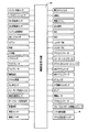
差動部11が非無段変速状態とされて変速機構10が有段変速機として機能する場合には、切換クラッチC0および切換ブレーキB0の何れかが係合させられ、且つ第1クラッチC1、第2クラッチC2、第3クラッチC3、第1ブレーキB1、および第2ブレーキB2が図2に示す組み合わせで選択的に係合作動させられることにより、第1速ギヤ段(第1変速段)乃至第7速ギヤ段(第7変速段)のいずれか或いは後進ギヤ段(後進変速段)或いはニュートラルが選択的に成立させられ、前進段では、隣接するギヤ段の変速比間が略等比的に変化する変速機構10のトータル変速比γT(=入力軸14の回転速度NIN/出力軸22の回転速度NOUT )が各ギヤ段毎に段階的に得られ、且つそれのトータル変速比幅(=第1速ギヤ段の変速比γT1/第7速ギヤ段の変速比γT7) が広範囲に得られるようになっている。この変速機構10のトータル変速比γTは、差動部11の変速比γ0と自動変速部20の変速比γAとに基づいて形成される変速機構10全体としてのトータル変速比γTである。
When the
図2の係合作動表に詳しく示されるように、切換クラッチC0、第1クラッチC1および第2ブレーキB2の係合により、変速比γT1が最大値例えば「3.683」程度である第1速ギヤ段が成立させられ、切換ブレーキB0、第1クラッチC1および第2ブレーキB2の係合により、変速比γT2が第1速ギヤ段よりも小さい値例えば「2.669」程度である第2速ギヤ段が成立させられ、切換クラッチC0、第1クラッチC1および第1ブレーキB1の係合により、変速比γT3が第2速ギヤ段よりも小さい値例えば「1.909」程度である第3速ギヤ段が成立させられ、切換ブレーキB0、第1クラッチC1および第1ブレーキB1の係合により、変速比γT4が第3速ギヤ段よりも小さい値例えば「1.383」程度である第4速ギヤ段が成立させられ、切換クラッチC0、第1クラッチC1および第3クラッチC3の係合により、変速比γT5が第4速ギヤ段よりも小さい値例えば「1.000」程度である第5速ギヤ段が成立させられ、切換クラッチC0、第3クラッチC3およびブレーキB1の係合により、変速比γT6が第5速ギヤ段よりも小さい値例えば「0.661」程度である第6速ギヤ段が成立させられ、切換ブレーキB0、第3クラッチC3および第1ブレーキB1の係合により、変速比γT7が第6速ギヤ段よりも小さい値例えば「0.479」程度である第7速ギヤ段が成立させられる。また、第1クラッチC1又は第2クラッチC2と第2ブレーキB2との係合により、変速比γRが第2速ギヤ段と第3速ギヤ段との間の値例えば「1.951」程度であるエンジン走行用またはモータ走行用後進ギヤ段が成立させられる。なお、この後進ギヤ段は、通常、差動部11の無段変速状態において成立させられる。また、ニュートラル「N」状態とする場合には、例えばブレーキB2のみが係合される。
As shown in detail in the engagement operation table of FIG. 2, the first speed in which the gear ratio γT1 is the maximum value, for example, about “3.683” due to the engagement of the switching clutch C0, the first clutch C1, and the second brake B2. When the gear stage is established and the switching brake B0, the first clutch C1, and the second brake B2 are engaged, the second speed in which the gear ratio γT2 is smaller than the first speed gear stage, for example, about “2.669”. The third speed in which the gear stage is established and the gear ratio γT3 is smaller than the second gear stage, for example, about “1.909” by the engagement of the switching clutch C0, the first clutch C1, and the first brake B1. A gear stage is established, and the gear ratio γT4 is smaller than the third gear stage, for example, about “1.383” by engagement of the switching brake B0, the first clutch C1, and the first brake B1. The fifth speed in which the gear stage is established and the gear ratio γT5 is smaller than the fourth speed gear stage by the engagement of the switching clutch C0, the first clutch C1, and the third clutch C3, for example, about “1.000”. The sixth gear stage in which the gear stage is established and the gear ratio γT6 is smaller than the fifth gear stage, for example, about “0.661” due to the engagement of the switching clutch C0, the third clutch C3, and the brake B1. Is established, and the engagement of the switching brake B0, the third clutch C3 and the first brake B1 results in the seventh speed gear stage in which the gear ratio γT7 is smaller than the sixth speed gear stage, for example, about “0.479”. Is established. Further, due to the engagement of the first clutch C1 or the second clutch C2 and the second brake B2, the gear ratio γR is a value between the second speed gear stage and the third speed gear stage, for example, about “1.951”. A reverse gear for engine traveling or motor traveling is established. This reverse gear is normally established when the
上記の説明および図2から明らかなように、本実施例の変速機構10では、切換クラッチC0および切換ブレーキB0のうちの一方の解放と他方の係合とで達成するクラッチツウクラッチ変速による2段階の変速と、第1クラッチC1、第2クラッチC2、第3クラッチC3、第1ブレーキB1、第2ブレーキB2のうちの一つの解放と他の1つ係合とで達成するクラッチツウクラッチ変速による4段階の変速とが組み合わせられることにより、前進7段の変速が行われるようになっている。すなわち、第1速ギヤ段と第2速ギヤ段との間、第2速ギヤ段と第3速ギヤ段との間、第3速ギヤ段と第4速ギヤ段との間、第4速ギヤ段と第5速ギヤ段との間、第6速ギヤ段と第7速ギヤ段との間が、第1変速部(差動部11)の変速と第2変速部(自動変速部20)の変速とが同じ変速期間内に同時に実行されることにより切り換えられ、第5速ギヤ段と第6速ギヤ段との間が専ら第2変速部のクラッチツウクラッチ変速により切り換えられる。
As is apparent from the above description and FIG. 2, in the speed change mechanism 10 of the present embodiment, two steps are achieved by clutch-to-clutch shift achieved by releasing one of the switching clutch C0 and the switching brake B0 and engaging the other. And the clutch-to-clutch shift achieved by releasing one of the first clutch C1, the second clutch C2, the third clutch C3, the first brake B1, and the second brake B2 and engaging the other one. By combining the four-stage shift, a forward seven-stage shift is performed. That is, between the first speed gear stage and the second speed gear stage, between the second speed gear stage and the third speed gear stage, between the third speed gear stage and the fourth speed gear stage, Between the gear stage and the fifth speed gear stage and between the sixth speed gear stage and the seventh speed gear stage, the shift of the first transmission unit (differential unit 11) and the second transmission unit (
また、差動部11が無段変速状態とされて変速機構10が無段変速機として機能する場合には、切換クラッチC0および切換ブレーキB0が共に解放されて差動部11が無段変速機として機能し、且つ差動部11に直列の自動変速部20が前進4段の有段変速機として機能することにより、自動変速部20の前進4段から自動的にギヤ段が選択されることにより自動変速部20の変速比γAが段階的に変化するにも拘わらず全体のトータル変速比γTが連続的に変化するように、自動変速部20に入力される回転速度すなわち伝達部材18の回転速度が無段的に変化させられてその変速段Mにおいて無段的な変速比幅が得られる。したがって、変速機構10のトータル変速比γTが無段階に得られるようになる。
Further, when the
すなわち、変速機構10が無段変速機として機能する場合には、切換クラッチC0および切換ブレーキB0が共に解放された状態で、自動変速部20の第1速、第2速、第3速、第4速の各ギヤ段に対し、その各ギヤ段の間において無段的に連続して変化するトータル変速比γTとなるように、差動部11の変速比γ0が制御させられて、変速機構10全体としてのトータル変速比γTが無段階に得られる。
That is, when the transmission mechanism 10 functions as a continuously variable transmission, the first speed, the second speed, the third speed, the first speed of the
図3は、無段変速部或いは第1変速部として機能する差動部11と第2変速部として機能する自動変速部20とから構成される変速機構10において、ギヤ段毎に連結状態が異なる各回転要素の回転速度の相対関係を直線上で表すことができる共線図を示している。この図3の共線図は、各遊星歯車装置24、26、28のギヤ比ρの関係を示す横軸と、相対的回転速度を示す縦軸とから成る二次元座標であり、横線のうちの下側の横線X1が回転速度零を示し、上側の横線X2が相対回転速度「1.0」すなわち入力軸14に連結されたエンジン8の回転速度NEを示し、破線に示す横線XGが伝達部材18の回転速度を示している。
FIG. 3 shows a transmission mechanism 10 that includes a
また、差動部11を構成する動力分配機構16の3つの要素に対応する3本の縦線Y1、Y2、Y3は、左側から順に第2回転要素RE2に対応するサンギヤS0、第1回転要素RE1に対応するキャリヤCA0、第3回転要素RE3に対応するリングギヤR0の相対回転速度を示すものであり、それら縦線の間隔は第1遊星歯車装置24のギヤ比ρ0に応じて定められている。さらに、自動変速部20の4本の縦線Y4、Y5、Y6、Y7は、左から順に、第4回転要素RE4に対応する第1リングギヤR1を、第5回転要素(第5要素)RE5に対応し相互に連結された第1キャリヤCA1及び第2リングギヤR2を、第6回転要素(第6要素)RE6に対応する第2キャリヤCA2を、第7回転要素(第7要素)RE7に対応し且つ相互に連結された第1サンギアS1および第2サンギヤS2を、それぞれ表し、それらの間隔は第1遊星歯車装置26のギヤ比ρ2および第2遊星歯車装置28のギヤ比ρ3に応じてそれぞれ定められている。共線図の縦軸間の関係においてサンギヤとキャリヤとの間が「1」に対応する間隔とされるとキャリヤとリングギヤとの間が遊星歯車装置のギヤ比ρに対応する間隔とされる。すなわち、差動部11では縦線Y1とY2との縦線間が「1」に対応する間隔に設定され、縦線Y2とY3との間隔はギヤ比ρ0に対応する間隔に設定される。また、自動変速部20では各第2、第3遊星歯車装置26、28毎にそのサンギヤとキャリヤとの間が「1」に対応する間隔に設定され、キャリヤとリングギヤとの間がρに対応する間隔に設定される。
Also, three vertical lines Y1, Y2, Y3 corresponding to the three elements of the
上記図3の共線図を用いて表現すれば、本実施例の変速機構10は、動力分配機構16(差動部11)において、第1遊星歯車装置24の第1回転要素RE1(キャリヤCA0)が入力軸14すなわちエンジン8に連結されるとともに切換クラッチC0を介して第2回転要素(サンギヤS0)RE2と選択的に連結され、第2回転要素RE2が第1電動機M1に連結されるとともに切換ブレーキB0を介してケース12に選択的に連結され、第3回転要素(リングギヤR0)RE3が伝達部材18および第2電動機M2に連結されて、入力軸14の回転を伝達部材18を介して自動変速部20へ伝達する(入力させる)ように構成されている。このとき、Y2とX2の交点を通る斜めの直線L0により第1サンギヤS1の回転速度と第1リングギヤR1の回転速度との相対関係が示される。
If expressed using the collinear diagram of FIG. 3, the speed change mechanism 10 of the present embodiment includes the first rotating element RE1 (carrier CA0) of the first
例えば、上記切換クラッチC0および切換ブレーキB0の解放により、第1回転要素RE1乃至第3回転要素RE3を相互に相対回転可能とする無段変速状態(差動状態)、例えば少なくとも第2回転要素RE2および第3回転要素RE3を互いに異なる速度にて回転可能とする無段変速状態(差動状態)に切換えられたときは、第1電動機M1の回転速度を制御することによって直線L0と縦線Y1との交点で示されるサンギヤS0の回転が上昇或いは下降させられると、直線L0と縦線Y3との交点で示される、車速Vに拘束されるリングギヤR0の回転速度が略一定である場合には、直線L0と縦線Y2との交点で示されるキャリヤCA0の回転速度すなわちエンジン回転速度NEが上昇或いは下降させられる。 For example, when the switching clutch C0 and the switching brake B0 are released, the first rotation element RE1 to the third rotation element RE3 are allowed to rotate relative to each other, for example, at least the second rotation element RE2. And the third rotation element RE3 are switched to a continuously variable transmission state (differential state) in which the third rotation element RE3 can be rotated at different speeds, the straight line L0 and the vertical line Y1 are controlled by controlling the rotation speed of the first motor M1. When the rotation of the sun gear S0 indicated by the intersection with the vehicle is raised or lowered, the rotation speed of the ring gear R0 restricted by the vehicle speed V indicated by the intersection of the straight line L0 and the vertical line Y3 is substantially constant. The rotational speed of the carrier CA0 indicated by the intersection of the straight line L0 and the vertical line Y2, that is, the engine rotational speed NE is increased or decreased.
また、切換クラッチC0の係合によりサンギヤS0とキャリヤCA0とが連結されると、動力分配機構16は上記3回転要素RE1、RE2、RE3が一体回転して第2回転要素RE2および第3回転要素RE3を互いに異なる速度にて回転可能としない非差動状態とされるので、直線L0は横線X2と一致させられ、エンジン回転速度NEと同じ回転で伝達部材18が回転させられる。また、切換ブレーキB0の係合によりサンギヤS0がケース12に連結されると、動力分配機構16は第2回転要素RE2の回転が停止させられて少なくとも第2回転要素RE2および第3回転要素RE3を互いに異なる速度にて回転可能としない非差動状態とされるので、直線L0は図3に示す状態となって差動部11が増速機構として機能させられ、その直線L0と縦線Y3との交点で示されるリングギヤR0の回転速度すなわち伝達部材18の回転速度は、エンジン回転速度NEよりも増速された回転で自動変速部20へ入力される。
When the sun gear S0 and the carrier CA0 are connected by the engagement of the switching clutch C0, the
また、自動変速部20において第4回転要素RE4は第1クラッチC1を介して伝達部材18に選択的に連結されるとともに第1ブレーキB1を介してケース12に選択的に連結され、第5回転要素RE5は第3クラッチC3を介して伝達部材18に選択的に連結されるとともに第2ブレーキB2を介してケース12に選択的に連結され、第6回転要素RE6は出力軸22に連結され、第7回転要素RE7は第1クラッチC1を介して伝達部材18に選択的に連結されている。
Further, in the
自動変速部20では、図3に示すように、切換クラッチC0と第1クラッチC1と第2ブレーキB2とが係合させられることにより、第7回転要素RE7の回転速度を示す縦線Y7と横線X2との交点と第5回転要素RE5の回転速度を示す縦線Y5と横線X1との交点とを通る斜めの直線L1と、出力軸22と連結された第6回転要素RE6の回転速度を示す縦線Y6との交点で第1速の出力軸22の回転速度が示される。同様に、切換ブレーキB0と第1クラッチC1と第2ブレーキB2とが係合させられることにより決まる斜めの直線L2と出力軸22と連結された第6回転要素RE6の回転速度を示す縦線Y6との交点で第2速の出力軸22の回転速度が示され、切換クラッチC0と第1クラッチC1と第1ブレーキB1とが係合させられることにより決まる斜めの直線L3と出力軸22と連結された第6回転要素RE6の回転速度を示す縦線Y6との交点で第3速の出力軸22の回転速度が示され、切換ブレーキB0と第1クラッチC1と第1ブレーキB1とが係合させられることにより決まる直線L4と出力軸22と連結された第6回転要素RE6の回転速度を示す縦線Y6との交点で第4速の出力軸22の回転速度が示され、切換クラッチC0と第1クラッチC1と第3クラッチC3とが係合させられることにより決まる水平な直線L5と出力軸22と連結された第6回転要素RE6の回転速度を示す縦線Y6との交点で第5速の出力軸22の回転速度が示され、切換クラッチC0と第3クラッチC3と第1ブレーキB1とが係合させられることにより決まる斜めの直線L6と出力軸22と連結された第6回転要素RE6の回転速度を示す縦線Y6との交点で第6速の出力軸22の回転速度が示され、切換ブレーキB0と第3クラッチC3と第1ブレーキB1とが係合させられることにより決まる斜めの直線L7と出力軸22と連結された第6回転要素RE6の回転速度を示す縦線Y6との交点で第7速の出力軸22の回転速度が示される。上記第1速、第3速、第5速、第6速では、切換クラッチC0が係合させられる結果、エンジン回転速度NEと同じ回転速度で第4回転要素RE4、第5回転要素RE5、或いは第7回転要素RE7に差動部11すなわち動力分配機構16からの動力が入力される。しかし、第2速、第4速、第7速では、切換クラッチC0に替えて切換ブレーキB0が係合させられる結果、第5回転要素RE5或いは第7回転要素RE7に差動部11からの動力がエンジン回転速度NEよりも高い回転速度で入力される。
In the
図4は、本実施例の変速機構10を制御するための電子制御装置40に入力される信号及びその電子制御装置40から出力される信号を例示している。この電子制御装置40は、CPU、ROM、RAM、及び入出力インターフェースなどから成る所謂マイクロコンピュータを含んで構成されており、RAMの一時記憶機能を利用しつつROMに予め記憶されたプログラムに従って信号処理を行うことによりエンジン8、第1、第2電動機M1、M2に関するハイブリッド駆動制御、自動変速部20の変速制御等の駆動制御を実行するものである。
FIG. 4 illustrates a signal input to the
電子制御装置40には、図4に示すような各センサやスイッチなどから、エンジン水温TEMPWを表す信号、シフトポジションPSHを表す信号、エンジン8の回転速度であるエンジン回転速度NEを表す信号、ギヤ比列設定値を表す信号、Mモード(手動変速走行モード)を指令する信号、エアコンの作動を表す信号、出力軸22の回転速度NOUTに対応する車速Vを表す信号、自動変速部20の作動油温を表す信号、サイドブレーキ操作を表す信号、フットブレーキ操作を表す信号、触媒温度を表す信号、運転者の出力要求量に対応するアクセルペダルの操作量であるアクセル開度θACCを表す信号、カム角を表す信号、スノーモード設定を表す信号、車両の前後加速度Gを表す信号、オートクルーズ走行を表す信号、車両の重量(車重)を表す信号、各車輪の車輪速を表す信号、変速機構10を有段変速機として機能させるために差動部11(動力分配機構16)を有段変速状態(ロック状態)に切り換えるための有段スイッチ操作の有無を表す信号、変速機構10を無段変速機として機能させるために差動部11(動力分配機構16)を無段変速状態(差動状態)に切り換えるための無段スイッチ操作の有無を表す信号、第1電動機M1の回転速度NM1(以下、第1電動機回転速度NM1という)を表す信号、第2電動機M2の回転速度NM2(以下、第2電動機回転速度NM2という)を表す信号、蓄電装置60(図5参照)の充電容量(充電状態)SOCを表す信号などが、各センサ等からそれぞれ供給される。
The
また、上記電子制御装置40からは、エンジン出力を制御するエンジン出力制御装置43(図5参照)への制御信号例えばエンジン8の吸気管95に備えられた電子スロットル弁96のスロットル弁開度θTHを操作するスロットルアクチュエータ97への駆動信号や燃料噴射装置98による上記吸気管95或いはエンジン8の筒内への燃料供給量を制御する燃料供給量信号や点火装置99によるエンジン8の点火時期を指令する点火信号、過給圧を調整するための過給圧調整信号、電動エアコンを作動させるための電動エアコン駆動信号、電動機M1およびM2の作動を指令する指令信号、シフトインジケータを作動させるためのシフトポジション(操作位置)表示信号、ギヤ比を表示させるためのギヤ比表示信号、スノーモードであることを表示させるためのスノーモード表示信号、制動時の車輪のスリップを防止するABSアクチュエータを作動させるためのABS作動信号、Mモードが選択されていることを表示させるMモード表示信号、差動部11や自動変速部20の油圧式摩擦係合装置の油圧アクチュエータを制御するために油圧制御回路42(図5参照)に含まれる電磁弁を作動させるバルブ指令信号、この油圧制御回路42の油圧源である電動油圧ポンプを作動させるための駆動指令信号、電動ヒータを駆動するための信号、クルーズコントロール制御用コンピュータへの信号等が、それぞれ出力される。
A control signal from the
図5は、電子制御装置40による制御機能の要部を説明する機能ブロック線図である。図5において、有段変速制御手段54は、例えば記憶手段56に予め記憶された図6の実線および一点鎖線に示す変速線図(関係、変速マップ)から車速Vおよび自動変速部20の要求出力トルクTOUTで示される車両状態に基づいて、変速機構10の変速を実行すべきか否かを判断し、その判断した変速段が得られるように自動変速部20の自動変速制御を実行する。このとき、有段変速制御手段54は、例えば図2に示す係合表に従って変速段が達成されるように、切換クラッチC0および切換ブレーキB0を含む変速に関与する油圧式摩擦係合装置を係合および/または解放させる指令(変速出力指令、油圧指令)を直接的或いは間接的に油圧制御回路42へ出力する。油圧制御回路42は、その指令に従って、例えば変速に関与する解放側の油圧式摩擦係合装置を解放すると共に、変速に関与する係合側の油圧式摩擦係合装置を係合して自動変速部20の変速が実行されるように、油圧制御回路42内の電磁弁を作動させてその変速に関与する油圧式摩擦係合装置の油圧アクチュエータを作動させる。
FIG. 5 is a functional block diagram illustrating a main part of the control function by the
ハイブリッド制御手段52は、無段変速モードが選択された場合は無段変速制御手段として機能するものであり、変速機構10の無段変速状態すなわち差動部11の差動状態においてエンジン8を効率のよい作動域で作動させる一方で、エンジン8と第2電動機M2との駆動力の配分や第1電動機M1の発電による反力を最適になるように変化させ、差動部11の電気的な無段変速機としての変速比γ0を制御し、トータル変速比γTを無段階に制御する。例えば、そのときの走行車速において、運転者の出力要求量としてのアクセル開度θACCや車速Vから車両の目標(要求)出力を算出し、その車両の目標出力と充電要求値から必要なトータル目標出力を算出し、そのトータル目標出力が得られるように伝達損失、補機負荷、第2電動機M2のアシストトルク等を考慮して目標エンジン出力を算出し、その目標エンジン出力が得られるエンジン回転速度NEとエンジントルクTEとなるようにトータル変速比γTおよびエンジン8の出力を制御するとともに第1電動機M1の発電量を制御する。
The
ハイブリッド制御手段52は、その制御を動力性能や燃費向上などのために、上記無段変速制御中において自動変速部20の変速段を考慮して実行する。このようなハイブリッド制御では、エンジン8を効率のよい作動域で作動させるために定まるエンジン回転速度NEと車速Vおよび自動変速部20の変速段で定まる伝達部材18の回転速度とを整合させるために、差動部11が電気的な無段変速機として機能させられる。すなわち、ハイブリッド制御手段52は、エンジン回転速度NEとエンジン8の出力トルク(エンジントルク)TEとで構成される二次元座標内において無段変速走行の時に運転性と燃費性とを両立するように予め実験的に求められて例えば記憶手段56に記憶された図示しないエンジン8の最適燃費率曲線(燃費マップ、関係)に沿ってエンジン8が作動させられるように、例えば目標出力(トータル目標出力、要求駆動力)を充足するために必要なエンジン出力を発生するためのエンジントルクTEとエンジン回転速度NEとなるように、変速機構10のトータル変速比γTの目標値を定め、その目標値が得られるように自動変速部20の変速段を考慮して差動部11の変速比γ0を制御し、トータル変速比γTをその変速可能な変化範囲内例えば13〜0.5の範囲内で制御する。
The hybrid control means 52 executes the control in consideration of the gear position of the
このとき、ハイブリッド制御手段52は、第1電動機M1により発電された電気エネルギをインバータ58を通して蓄電装置60や第2電動機M2へ供給するので、エンジン8の動力の主要部は機械的に伝達部材18へ伝達されるが、エンジン8の動力の一部は第1電動機M1の発電のために消費されてそこで電気エネルギに変換され、インバータ58を通してその電気エネルギが第2電動機M2へ供給され、その第2電動機M2が駆動されて第2電動機M2から伝達部材18へ伝達される。この電気エネルギの発生から第2電動機M2で消費されるまでに関連する機器により、エンジン8の動力の一部を電気エネルギに変換し、その電気エネルギを機械的エネルギに変換するまでの電気パスが構成される。
At this time, the hybrid control means 52 supplies the electric energy generated by the first electric motor M1 to the
また、ハイブリッド制御手段52は、スロットル制御のためにスロットルアクチュエータ97により電子スロットル弁96を開閉制御させる他、燃料噴射制御のために燃料噴射装置98による燃料噴射量や噴射時期を制御させ、点火時期制御のためにイグナイタ等の点火装置99による点火時期を制御させる指令を単独で或いは組み合わせてエンジン出力制御装置43に出力して、必要なエンジン出力を発生するようにエンジン8の出力制御を実行するエンジン出力制御手段を機能的に備えている。エンジン出力制御装置43は、ハイブリッド制御手段52による指令に従って、スロットル制御のためにスロットルアクチュエータ97により電子スロットル弁96を開閉制御する他、燃料噴射制御のために燃料噴射装置98による燃料噴射を制御し、点火時期制御のためにイグナイタ等の点火装置99による点火時期を制御するなどしてエンジントルク制御を実行する。
Further, the hybrid control means 52 controls the fuel injection amount and the injection timing by the
また、ハイブリッド制御手段52は、エンジン8の停止又はアイドル状態に拘わらず、差動部11の電気的CVT機能(差動作用)によって車両をモータ走行させることができる。図6の実線Eは、車両の発進/走行用(以下、走行用という)の駆動力源をエンジン8と電動機例えば第2電動機M2とで切り換えるための、言い換えればエンジン8を走行用の駆動力源として車両を発進/走行(以下、走行という)させる所謂エンジン走行と第2電動機M2を走行用の駆動力源として車両を走行させる所謂モータ走行とを切り換えるための、エンジン走行領域とモータ走行領域との境界線である。この図6の境界線(実線E)に示される関係は、車速Vと駆動力関連値である出力トルクTOUTとをパラメータとする二次元座標で構成された駆動力源切換線図(駆動力源マップ)の一例である。この駆動力源切換線図は、例えば同じ図6中の実線および一点鎖線に示す変速線図(変速マップ)と共に記憶手段56に予め記憶されている。
Further, the hybrid control means 52 can drive the vehicle by the electric CVT function (differential action) of the
そして、ハイブリッド制御手段52は、例えば図6の駆動力源切換線図から車速Vと要求出力トルクTOUTとで示される車両状態に基づいてモータ走行領域とエンジン走行領域との何れであるかを判断してモータ走行或いはエンジン走行を実行する。このように、ハイブリッド制御手段52によるモータ走行は、図6から明らかなように一般的にエンジン効率が高トルク域に比較して低いとされる比較的低出力トルクTOUT域すなわち低エンジントルクTE域、或いは車速Vの比較的低車速域すなわち低負荷域で実行される。よって、通常はモータ発進がエンジン発進に優先して実行されるが、例えば車両発進時に図6の駆動力源切換線図のモータ走行領域を超える要求出力トルクTOUTすなわち要求エンジントルクTEとされる程大きくアクセルペダルが踏込操作されるような車両状態によってはエンジン発進も通常実行されるものである。 Then, for example, the hybrid control means 52 determines whether the motor travel region or the engine travel region is based on the vehicle state indicated by the vehicle speed V and the required output torque TOUT from the driving force source switching diagram of FIG. Then, motor running or engine running is executed. As described above, the motor traveling by the hybrid control means 52 is, as is apparent from FIG. 6, generally a relatively low output torque TOUT region, that is, a low engine torque TE region in which the engine efficiency is generally lower than that in the high torque region. Alternatively, it is executed in a relatively low vehicle speed range of the vehicle speed V, that is, a low load range. Therefore, the motor start is usually executed in preference to the engine start. For example, when the vehicle starts, the required output torque TOUT exceeding the motor travel region in the driving force source switching diagram of FIG. Depending on the vehicle state in which the accelerator pedal is largely depressed, the engine is normally started.
ハイブリッド制御手段52は、上記のモータ走行時には、停止しているエンジン8の引き摺りを抑制して燃費を向上させるために、差動部11の電気的CVT機能(差動作用)によって、第1電動機回転速度NM1を負の回転速度で制御例えば空転させて、差動部11の差動作用により必要に応じてエンジン回転速度NEを零乃至略零に維持することも可能である。
The hybrid control means 52 uses the electric CVT function (differential action) of the
また、ハイブリッド制御手段52は、エンジン走行領域であっても、上述した電気パスによる第1電動機M1からの電気エネルギおよび/または蓄電装置60からの電気エネルギを第2電動機M2へ供給し、その第2電動機M2を駆動して駆動輪38にトルクを付与することにより、エンジン8の動力を補助するための所謂トルクアシストが可能である。よって、本実施例のエンジン走行には、エンジン走行+モータ走行も含むものとする。
Further, even in the engine traveling region, the hybrid control means 52 supplies the second motor M2 with the electric energy from the first electric motor M1 and / or the electric energy from the
また、ハイブリッド制御手段52は、車両の停止中又は走行中に拘わらず、差動部11の電気的CVT機能によって第1電動機回転速度NM1および/または第2電動機回転速度NM2を制御してエンジン回転速度NEを略一定に維持したり任意の回転速度に回転制御することができる。例えば、図3の共線図からもわかるようにハイブリッド制御手段52は車両走行中にエンジン回転速度NEを引き上げる場合には、車速V(駆動輪38)に拘束される第2電動機回転速度NM2を略一定に維持しつつ第1電動機回転速度NM1の引き上げを実行する。
Further, the hybrid control means 52 controls the first motor rotation speed NM1 and / or the second motor rotation speed NM2 by the electric CVT function of the
切換制御手段50は、車両状態に基づいて切換用係合装置(切換クラッチC0または切換ブレーキB0)の係合/解放を切り換えることにより、前記無段変速状態すなわち前記差動状態と前記有段変速状態すなわち前記ロック状態との間で変速状態を選択的に切り換える。例えば、切換制御手段50は、要求出力軸トルクTOUTおよび車速Vにより示される車両状態が記憶手段56に予め記憶された前記図6の無段領域内であるが有段領域内であるか基づいて、変速機構10を無段変速状態とする無段領域内であるか或いは変速機構10を有段変速状態とする有段領域内であるかを判定し、切換クラッチC0或いは切換ブレーキB0の係合とそれら切換クラッチC0および切換ブレーキB0の解放とを切り換えることにより、変速機構10を前記無段変速状態と前記有段変速状態とのいずれかに選択的に切り換える。
The switching control means 50 switches the engagement / release of the switching engagement device (the switching clutch C0 or the switching brake B0) based on the vehicle state, so that the continuously variable speed state, that is, the differential state and the stepped speed change. The shift state is selectively switched between the state, that is, the lock state. For example, the switching
すなわち、切換制御手段50は有段変速制御領域内であると判定した場合は、ハイブリッド制御手段52に対してハイブリッド制御或いは無段変速制御を不許可すなわち禁止とする信号を出力するとともに、有段変速制御手段54に対して予め設定された有段変速時の変速を許可し、その有段変速制御手段54の変速判断にしたがって切換クラッチC0または切換ブレーキB0を係合させる。このときの有段変速制御手段54は、記憶手段56に予め記憶された例えば図6に示す変速線図に従って自動変速部20の前進7速の自動変速制御を実行する。例えば記憶手段56に予め記憶された図2は、このときの変速において選択される油圧式摩擦係合装置すなわちC0、C1、C2、C3、B0、B1、B2の作動の組み合わせを示している。すなわち、変速機構10全体すなわち差動部11および自動変速部20が所謂有段式自動変速機として機能し、図2に示す係合表に従って変速段が達成される。
That is, when the switching control means 50 determines that it is within the stepped shift control region, it outputs a signal for disabling or prohibiting the hybrid control or continuously variable shift control to the hybrid control means 52, and The shift control means 54 is allowed to perform a shift at the time of a preset stepped shift, and the switching clutch C0 or the switching brake B0 is engaged according to the shift determination of the stepped shift control means 54. At this time, the stepped shift control means 54 executes automatic shift control for the seventh forward speed of the
しかし、切換制御手段50は、要求出力軸トルクTOUTおよび車速Vにより示される車両状態が図6の無段領域内であると判定した場合は、変速機構10全体として無段変速状態が得られるようにするために差動部11を無段変速状態として無段変速可能とするように切換クラッチC0および切換ブレーキB0を解放させる指令を油圧制御回路42へ出力する。同時に、ハイブリッド制御手段52に対してハイブリッド制御を許可する信号を出力するとともに、有段変速制御手段54には、予め設定された無段変速時の変速段に固定する信号を出力するか、或いは記憶手段56に予め記憶された例えば図6に示す変速線図に従って自動変速部20を自動変速することを許可する信号を出力する。この場合、有段変速制御手段54により、自動変速部20は図2の係合表内において切換クラッチC0および切換ブレーキB0の係合を除いた前進4速の変速段、すなわち第1クラッチC1および第2ブレーキB2の係合により達成される第1のギヤ段(変速比γA=3.683) 、第1クラッチC1および第1ブレーキB1の係合により達成される第2のギヤ段(変速比γA=1.909) 、第1クラッチC1および第3クラッチC3の係合により達成される第3のギヤ段(変速比γA=1.000) 、第3クラッチC3および第1ブレーキB1の係合により達成される第4のギヤ段(変速比γA=0.661) で自動変速が行われる。このように、切換制御手段50により無段変速状態に切り換えられた差動部11が無段変速機として機能し、それに直列の自動変速部20が有段変速機として機能することにより、適切な大きさの駆動力が得られると同時に、自動変速部20の第1、第2、第3、第4のギヤ段に対しその自動変速部20に入力される回転速度すなわち伝達部材18の回転速度が無段的に変化させられて各ギヤ段は無段的な変速比幅が得られる。したがって、その各ギヤ段の間が無段的に連続変化可能な変速比となって変速機構10全体として無段変速状態となりトータル変速比γTが無段階に得られるようになる。
However, when the switching control means 50 determines that the vehicle state indicated by the required output shaft torque TOUT and the vehicle speed V is within the continuously variable region of FIG. 6, the continuously variable transmission state is obtained as a whole of the transmission mechanism 10. In order to achieve this, a command for releasing the switching clutch C0 and the switching brake B0 is output to the
なお、図6は自動変速部20の変速判断の基となる記憶手段56に予め記憶された変速線図(関係、変速マップ)の一例であり、車速Vと駆動力関連値である要求出力トルクTOUTとをパラメータとする二次元座標で構成された変速線図の一例である。図6の実線はアップシフト線であり一点鎖線はダウンシフト線である。図6の破線は切換制御手段50により無段制御領域から有段制御領域への切換判定のための判定車速V1および判定出力トルクTOUT1を示している。つまり、図6の破線はハイブリッド車両の高速走行域を判定するための予め設定された高速走行判定値である判定車速V1の連なりである高車速判定線と、ハイブリッド車両の要求駆動力に関連する駆動力関連値例えば自動変速部20の出力トルクTOUTが高出力となる高出力走行域、高トルク走行域を判定するための予め設定された高出力走行判定値である判定出力トルクTOUT1の連なりである高出力走行判定線とを示している。さらに、図6の破線に対して2点鎖線に示すように有段制御領域と無段制御領域との判定にヒステリシスが設けられている。つまり、この図6は判定車速V1および判定出力トルクTOUT1を含む、車速Vと出力トルクTOUTとをパラメータとして切換制御手段50により有段制御領域と無段制御領域とのいずれであるかを領域判定するための予め記憶された切換線図(切換マップ、関係)である。なお、この切換線図を含めて変速マップとして記憶手段56に予め記憶されてもよい。また、この切換線図は判定車速V1および判定出力トルクTOUT1の少なくとも1つを含むものであってもよいし、車速Vおよび出力トルクTOUTの何れかをパラメータとする予め記憶された切換線であってもよい。
FIG. 6 is an example of a shift diagram (relationship, shift map) stored in advance in the storage means 56 that is a basis for shift determination of the
上記変速線図、切換線図、或いは駆動力源切換線図等は、マップとしてではなく実際の車速Vと判定車速V1とを比較する判定式、出力トルクTOUTと判定出力トルクTOUT1とを比較する判定式等として記憶されてもよい。例えば、この場合には、切換制御手段50は、車両状態例えば実際の車速Vが判定車速V1を越えたか否かを判定し、判定車速V1を越えたときには切換クラッチC0または切換ブレーキB0を係合して変速機構10を有段変速状態とする。また、切換制御手段50は、車両状態例えば自動変速部20の出力トルクTOUTが判定出力トルクTOUT1を越えたか否かを判定し、判定出力トルクTOUT1を越えたときには切換クラッチC0または切換ブレーキB0を係合させて変速機構10を有段変速状態とする。
The shift diagram, the switching diagram, the driving force source switching diagram, or the like is not a map but a judgment formula for comparing the actual vehicle speed V with the judgment vehicle speed V1, and compares the output torque TOUT with the judgment output torque TOUT1. It may be stored as a determination formula or the like. For example, in this case, the switching control means 50 determines whether or not the vehicle state, for example, the actual vehicle speed V has exceeded the determination vehicle speed V1, and when the determination vehicle speed V1 is exceeded, the switching clutch C0 or the switching brake B0 is engaged. Then, the transmission mechanism 10 is set to the stepped transmission state. Further, the switching control means 50 determines whether or not the vehicle state, for example, the output torque TOUT of the
図6の縦軸は出力軸トルクTOUTが示されていたが、要求駆動力関連値であればよい。要求駆動力関連値とは、車両の要求駆動力に1対1に対応するパラメータであって、駆動輪38での要求駆動トルク或いは駆動力のみならず、例えば自動変速部20の要求出力トルクTOUT、要求エンジントルクTE、要求車両加速度Gや、例えばアクセル開度θACC或いはスロットル弁開度θTH(或いは吸入空気量、空燃比、燃料噴射量)とエンジン回転速度NEとに基づいて算出されるエンジントルクTEなどの等の要求値である。また、上記駆動トルクは出力トルクTOUT等からデフ比、駆動輪38の半径等を考慮して算出されてもよいし、例えばトルクセンサ等によって直接検出されてもよい。上記他の各トルク等も同様である。
The vertical axis in FIG. 6 represents the output shaft torque TOUT, but it may be a required driving force related value. The required driving force-related value is a parameter corresponding to the required driving force of the vehicle on a one-to-one basis, and includes not only the required driving torque or driving force at the driving
また、前記判定車速V1は、例えば高速走行において変速機構10が無段変速状態とされるとかえって燃費が悪化するのを抑制するように、その高速走行において変速機構10が有段変速状態とされるように設定されている。また、前記判定トルクTOUT1は、例えば車両の高出力走行において第1電動機M1の反力トルクをエンジン8の高出力域まで対応させないで第1電動機M1を小型化するために、第1電動機M1からの電気エネルギの最大出力を小さくして配設可能とされた第1電動機M1の特性に応じて設定されている。
Further, the determination vehicle speed V1 is set such that the transmission mechanism 10 is set to the stepped transmission state at the high speed so that the fuel consumption is prevented from deteriorating, for example, when the transmission mechanism 10 is set to the continuously variable transmission state at the high speed. Is set to Further, the determination torque TOUT1 is obtained from the first motor M1 in order to reduce the size of the first motor M1 without causing the reaction torque of the first motor M1 to correspond to the high output range of the
図6の関係に示されるように、出力トルクTOUTが予め設定された判定出力トルクTOUT1以上の高トルク領域、或いは車速Vが予め設定された判定車速V1以上の高車速領域が、有段制御領域として設定されているので有段変速走行がエンジン8の比較的高トルクとなる高駆動トルク時、或いは車速の比較的高車速時において実行され、無段変速走行がエンジン8の比較的低トルクとなる低駆動トルク時、或いは車速の比較的低車速時すなわちエンジン8の常用出力域において実行されるようになっている。
As shown in the relationship of FIG. 6, the high torque region where the output torque TOUT is greater than or equal to the predetermined determination output torque TOUT1 or the high vehicle speed region where the vehicle speed V is equal to or greater than the predetermined determination vehicle speed V1 is the stepped control region. Therefore, the stepped variable speed travel is executed at the time of a high drive torque at which the
これによって、例えば、車両の低中速走行および低中出力走行では、変速機構10が無段変速状態とされて車両の燃費性能が確保されるが、自動変速部20が4段の変速段として機能するため第1電動機M1が発生すべき電気的エネルギ換言すれば第1電動機M1が伝える電気的エネルギの最大値を小さくできて第1電動機M1或いはそれを含む車両の駆動装置が一層小型化される。反対に、車速Vが前記判定車速V1を越えるような高速走行や、出力トルクTOUTが判定トルクTOUT1を越えるような高出力走行では、変速機構10が有段の変速機として作動する有段変速状態とされ専ら機械的な動力伝達経路でエンジン8の出力が駆動輪38へ伝達されて電気的な無段変速機として作動させる場合に発生する動力と電気エネルギとの間の変換損失が抑制されて燃費が向上させられる。
Thus, for example, in low and medium speed traveling and low and medium power traveling of the vehicle, the speed change mechanism 10 is set to a continuously variable transmission state to ensure fuel efficiency of the vehicle, but the
図7は、図6の変速線図に基づく変速の内容を説明するために、前記変速線図の一部を拡大した図である。図7においては説明の簡略化のため、図6において実線で表されたアップシフト線と一点鎖線で表されたダウンシフト線とが本図7においては重なり合っているものとされて一本の実線で表されており、また、図6において破線で表された無段領域から有段領域への切換線と二点鎖線で表された有段領域から無段領域への切換線とが本図7においては重なり合っているものとされて一本の破線SW1で表されている。図7において、破線SW1で表された切換線を介して上側に有段領域が、下側に無段領域が設けられている。有段領域には、動力伝達装置全体としての変速を実行するための有段時変速線A12、A23、A34が設けられると共に、それら有段時変速線A12、A23、A34と前記切換線によって定義される有段時変速段領域が車速の低い側(図中左側)から順にI、II、III、IVのように設けられている。そして、有段時変速段領域Iにおいては切換クラッチC0が係合され非差動状態とされた差動部11と有段変速部20の第1のギヤ段(最低速側のギヤ段)とを用いた変速状態(「有段第I速段」とよぶ。)とされ、有段時変速段領域IIにおいては、切換ブレーキB0が係合され非差動状態とされた差動部11と有段変速部20の第1のギヤ段とを用いた変速状態(「有段第II速段」とよぶ。)とされ、有段時変速段領域IIIにおいては、切換クラッチC0が係合され非差動状態とされた差動部11と有段変速部20の第2のギヤ段(二番目に低速側のギヤ段)とを用いた変速状態(「有段第III速段」とよぶ。)とされ、有段時変速段領域IVにおいては切換ブレーキB0が係合され非差動状態とされた差動部11と有段変速部20の第2のギヤ段とを用いた変速状態(「有段第IV速段」とよぶ。)とされる(図2参照)。なお、上述のように本図7においては切換線としては有段領域から無段領域への切換も無段領域から有段領域への切換についても一本の切換線であるとされているが、図6のように有段領域から無段領域への切換に用いられる切換線(2点鎖線)と、無段領域から有段領域への切換に用いられる切換線(破線)との間にヒステリシスが設けられる場合であっても同様に本発明の適用が可能である。また、本図7においてはアップシフト線とダウンシフト線が同一線によって表されているが、図6のようにアップシフト線とダウンシフト線とがそれぞれ定義されている場合であっても同様に本発明の適用が可能である。なお、前記有段第I速段乃至有段第IV速段は図2の作動表における1st乃至4thに対応するものである。また、本図においては省略されているが図2の作動表における5thないし7thに対応する有段第V速段乃至有段第VII速段も同様に定義される。
FIG. 7 is an enlarged view of a part of the shift diagram in order to explain the contents of the shift based on the shift diagram of FIG. In FIG. 7, for simplification of explanation, the upshift line represented by the solid line in FIG. 6 and the downshift line represented by the alternate long and short dash line are assumed to overlap in FIG. The switching line from the stepless region to the stepped region represented by the broken line in FIG. 6 and the switching line from the stepped region to the stepless region represented by the two-dot chain line are shown in FIG. In FIG. 7, they are overlapped and represented by a single broken line SW1. In FIG. 7, a stepped region is provided on the upper side and a stepless region is provided on the lower side through a switching line represented by a broken line SW1. The stepped region is provided with stepped shift lines A12, A23, A34 for executing the shift of the entire power transmission device, and is defined by the stepped shift lines A12, A23, A34 and the switching line. The stepped gear region is provided in the order of I, II, III, IV in order from the vehicle speed side (left side in the figure). In the stepped gear region I, the
一方、前記切換線SW1の下側の無段領域においては、有段変速部20の変速のための無段時変速線B13、B35が設けられると共に、それら無段時変速線B13、B35と前記切換線SW1によって定義される無段時変速段領域が車速の低い側(図中左側)から順にi、iii、vのように設けられている。そして、無段時変速段領域iにおいては切換クラッチC0および切換ブレーキB0の何れもが解放され差動状態とされた差動部11と有段変速部20の第1のギヤ段とを用いた無段変速状態(「無段第i速段」とよぶ。)とされ、無段時変速段領域iiiにおいては、差動状態とされた差動部11と有段変速部20の第2のギヤ段とを用いた無段変速状態(「無段第iii速段」とよぶ。)とされ、無段時変速段領域vにおいては、差動状態とされた差動部11と有段変速部20の第3のギヤ段とを用いた無段変速状態(「無段第v速段」とよぶ。)とされる。なお本図においては省略されているが、同様に無段第vii段も定義される。
On the other hand, in the continuously variable area below the switching line SW1, continuously variable transmission lines B13 and B35 for shifting the stepped
なお、本図において、切換線SW1が前記第1の制御マップに、無段時変速線B13、B35が前記第2の制御マップに、有段時変速線A12、A23、A34が前記第3の制御マップにそれぞれ相当する。 In this figure, the switching line SW1 is in the first control map, the continuously variable transmission lines B13, B35 are in the second control map, and the variable speed transmission lines A12, A23, A34 are in the third control map. Each corresponds to a control map.
このように表された各領域間を移動する、すなわち、本図7中の平面座標中の一点で表される車両の運転状態の軌跡が図中の切換線SW1、無段時変速線B13、B35、有段時変速線A12、A23、A34のいずれかを横切る場合には変速判断が行われて変速が実行されることとなる。ここで、例えば無段時変速段領域iiiに着目すると、無段時変速段領域iiiからの変速および無段時変速段領域iiiへの変速は図中の矢印SF4乃至SF6で表される。すなわち変速SF1は有段時変速段領域Iと有段時変速段領域IIとの間の変速を、変速SF2は有段時変速段領域IIとIIIとの間の変速を、変速SF3は有段時変速段領域IIIと有段時変速段領域IVとの間の変速を、変速SF4は無段時変速段領域iと無段時変速段領域iiiとの間の変速を、変速SF5は無段時変速段領域iiiと無段時変速段領域vとの間の変速を、変速SF6は無段時変速段領域iiiと有段時変速段領域IIとの間の変速を、変速SF7は無段時変速段領域iiiと有段時変速段領域IIIとの間の変速をそれぞれ表している。 The vehicle moves between the regions represented in this way, that is, the locus of the driving state of the vehicle represented by one point in the plane coordinates in FIG. 7 is the switching line SW1, the continuously variable transmission line B13, When crossing any one of B35 and the stepped shift line A12, A23, A34, a shift determination is made and the shift is executed. Here, for example, paying attention to the continuously variable speed region iii, the shift from the continuously variable speed region iii and the shift to the continuously variable speed region iii are represented by arrows SF4 to SF6 in the drawing. That is, the shift SF1 is a shift between the stepped gear region I and the stepped gear region II, the shift SF2 is a shift between the stepped gear regions II and III, and the shift SF3 is a step. Shifting between the stepped speed region III and the stepped shift region IV, shifting SF4 is shifting between the stepless shifting step region i and the stepless shifting step region iii, and shifting SF5 is stepless. The shift between the step-speed region iii and the stepless-speed step region v, the shift SF6 is the shift between the stepless-speed step region iii and the step-variable shift-step region II, and the shift SF7 is the stepless. The shift between the hour shift speed region iii and the stepped gear shift region III is shown.
このとき、無段時変速段領域iiiと切換線を介して接する有段時変速段領域としては有段時変速段領域IIおよびIIIがある。そして、これらの各領域について用いられる有段変速部20のギヤ段は、無段時変速段領域iiiにおいては第2のギヤ段である一方、有段時変速段領域IIにおいては、第2のギヤ段に隣接した第1のギヤ段であり、有段時変速段領域IIIにおいては第2のギヤ段である。したがって、無段時変速段領域iiiから有段時変速段IIへの変速SF6においては、自動変速部20の変速段は第2のギヤ段から第1のギヤ段への1段のシフトダウンが行われる。無段時変速段領域iiiから有段時変速段領域IIIへの変速SF7においては、自動変速部20の変速段は第2のギヤ段が維持される。このように、無段時変速段領域と、その無段時変速段領域と切換線を介して接する有段時変速段領域とにおいては、有段変速部20の変速段は同一又は隣接した変速段が用いられるようにされている。
At this time, there are stepped gear region II and III as the stepped gear region that contacts the continuously variable gear region iii via the switching line. The gear stage of the stepped
言い換えれば、差動部11における差動状態と非差動状態間の切換を伴う変速に際して、有段変速部20はそのときの変速段が維持されるか或いはその変速段に隣接する変速段に変速される。
In other words, at the time of shifting involving switching between the differential state and the non-differential state in the
また、有段時変速段領域IIと有段時変速段領域IIIとの間の変速である変速SF2に着目すると、変速SF2は有段第II速段から有段第III速段への変速であるから、図2の差動表より、差動部11における切換ブレーキB0の解放および切換クラッチC0の係合と、自動変速部20の第1のギヤ段から第2のギヤ段への変速との両方が同時期に実行される変速とからなりトータル変速比を切り換えるいわゆる同時変速とされている。すなわち、有段時変速線には、差動部11の差動状態と非差動状態を切り換えるとともに、有段部20のギヤ段の変更を実行する同時変速を実行するものが含まれる。なお、有段時変速段領域Iと有段時変速段領域IIとの間の変速SF1および有段時変速段領域IIIと有段時変速段領域IVとの間の変速SF3においては、図2の差動表より有段部20のギヤ段は維持されたまま、差動部11の切換クラッチC0および切換ブレーキB0の係合ないし解放状態が変更されることにより異なる非差動状態間の変更のみが実行されるので、前記同時変速には該当しない。
Focusing on the shift SF2 that is a shift between the stepped gear region II and the stepped gear region III, the shift SF2 is a shift from the stepped second speed to the stepped third speed. Therefore, from the differential table in FIG. 2, the release of the switching brake B0 and the engagement of the switching clutch C0 in the
ここで、有段領域において車速の上昇に伴って変速させられる変速段を車速の低い順に着目すると有段第I速段、有段第II速段、有段第III速段、有段第IV速段、有段第V速段、有段第VI速段、有段第VII速段の順であるが、これらの変速段において用いられる自動変速部20のギヤ段はそれぞれ、第1のギヤ段、第1のギヤ段、第2のギヤ段、第2のギヤ段、第3のギヤ段、第4のギヤ段、第4のギヤ段となっている。一方、無段領域において車速の上昇に伴って変速させられる変速段についても、同様に車速の低い順に着目すると無段第i速段、無段第iii速段、無段第v速段、無段第vii速段の順であるが、これらの変速段において用いられる自動変速部20のギヤ段はそれぞれ第1のギヤ段、第2のギヤ段、第3のギヤ段、第4のギヤ段となっている。なお、有段第V速段乃至有段第VII速段および無段第vii速段については、図7には図示されないが、図6の変速線図および図2の作動表より導かれる。このように、差動部11が非差動状態である場合において有段変速部20が車速の変化とともに変速させられる際の変速段の順序と、差動部11が作動状態である場合において有段変速部20が車速の変化とともに変速させられる際の変速段の順序とは、共に第1のギヤ段、第2のギヤ段、第3のギヤ段第4のギヤ段の順で同一である
Here, if attention is paid to the shift speeds that are shifted in accordance with the increase in the vehicle speed in the stepped region, the stepped first speed, stepped second speed, stepped third speed, stepped IV The gear positions of the
また、差動部11の非差動状態間の切換と自動変速部20の変速との両方を伴う変速を表す変速SF2においては、自動変速機20の変速段は第1のギヤ段から第2のギヤ段へ変速される。したがって、変速前後の自動変速機20の変速段のうち高速側の変速段は第2のギヤ段であり、この第2のギヤ段を用いる無段時変速段領域は無段時変速段領域iiiである。このとき、変速SF2に対応する有段時変速線A23と切換線SW1との交点Rは、前記無段時変速段領域iiiを形成する無段時変速線B13およびB35と切換線SW1とのそれぞれの交点PおよびQの間に位置するようにされている。このとき、無段時変速段領域iiiから差動部11の差動状態を非差動状態に切り換える場合の変速としては、差動部11の差動状態と非差動状態との切換と自動変速部20のギヤ段の変更を同時に実行する変速SF6(このような変速を「同時切換」と呼ぶ。)に加えて、差動部11の差動状態と非差動状態との切換のみを行い、自動変速部20のギヤ段はそのまま維持する変速SF5が設定される。すなわち、無段時変速段領域と有段時変速段領域との変速において、差動部11の差動状態と非差動状態との切換のみによって変速が実行できることとなる。
Further, in a shift SF2 that represents a shift involving both the switching between the non-differential states of the
言い換えれば、差動部11における異なる非差動状態間の切換と有段変速部20における変速との両方が同時に実行されることによってトータル変速比γTを切り換えるための変速点車速は、有段変速部20における変速の前後の変速段のうち高速側の変速段と同一の変速段を用いた有段変速部20と差動状態とされた差動部11との組み合わせにおいて、差動部11が差動状態から非差動状態へ切換えられようとする車両状態において走行するように設定された車速の範囲内に設定されるようにされている。
In other words, the shift point vehicle speed for switching the total gear ratio γT by simultaneously performing both switching between different non-differential states in the
また、変速線図において車両の運転状態を表す点の軌跡が無段時変速線B13およびB35をそれぞれ横切ることに対応する変速SF4およびSF5は、全体として無段変速機として作動する動力伝達装置における有段変速部20の変速のみを規定したものである。すなわち前記変速SF4およびSF5においては、有段変速部20は無段時変速線B13乃至B35に既定する変速を実行する一方、差動状態にある差動部11は有段変速部20の変速によりその変速比がステップ状に変化することによって、動力伝達装置全体のトータル変速比γTまでもがステップ状に変化することなく連続的に変化するように、有段変速部20の変速と同時もしくは略同時に有段変速部20と逆方向の変速をするなどの作動を実行する。従って、有段変速部20の変速のみを規定する無段時変速線の本数は、有段変速部20の変速に加え差動部11の非差動状態間の切換を規定する有段時変速線の本数よりも多くなることはない。
Further, the shifts SF4 and SF5 corresponding to the locus of points representing the driving state of the vehicle in the shift diagram crossing the continuously variable transmission lines B13 and B35, respectively, in the power transmission device that operates as a continuously variable transmission as a whole. Only the shift of the stepped
言い換えれば、所定の無段時変速段領域の出力トルクの大きい側(図中上側)には有段変速部20の変速を行うことなく差動部11を非差動状態から差動状態に切換えるのみで切換可能な有段時変速段領域が存在することとなるから、車両用動力伝達装置10に対する出力トルクもしくは出力の変化要求があった場合に、差動部11の差動状態と非差動状態との切換の有無にかかわらず有段変速部20においては同一の変速段が維持されるようにされている。
In other words, the
また、図7によれば、無段時変速段領域iiiにおいて用いられる有段変速部20の変速段は前記第2のギヤ段であり、一方、無段時変速段領域iiiと切換線を介して接する有段時変速段領域IIおよびIIIにおいて用いられる有段変速部20の変速段はそれぞれ前記第1のギヤ段および第2のギヤ段である。すなわち、図7中の一点で表される車両の走行状態が無段時変速段領域iiiにある状態から出力トルクもしくは出力の増加要求があった場合には変速SF6乃至SF7のいずれかが実行されることとなるが、これらの変速によっては自動変速部のギヤ段がアップ変速することがない。逆に図7中の一点で表される車両の走行状態が有段時変速段領域II乃至有段時変速段領域IIIにある状態から出力トルクもしくは出力の減少要求があった場合には変速SF6乃至SF7のいずれかが実行されることとなるが、これらの変速によっては自動変速部のギヤ段がダウン変速することがない。このように、出力トルクもしくは出力の増加要求があった場合の変速によっては自動変速部のギヤ段がアップ変速することがなく、また、出力トルクもしくは出力の減少要求があった場合の変速によっては自動変速部のギヤ段がダウン変速することがない。
Further, according to FIG. 7, the gear stage of the stepped
言い換えれば、前記車両用動力伝達装置に対する出力トルクもしくは出力の増加要求があった場合においてはエンジンの回転速度NEが減少することがないように、また、出力トルクもしくは出力の減少要求があった場合においてはエンジンの回転速度NEが増加することがないように、前記差動部の差動状態と非差動状態の切換、もしくはその切換に加えて前記有段変速部の変速が同時に実行されるようにされている。 In other words, when the output torque or output increase request for the vehicle power transmission device is requested, the engine rotational speed NE is not decreased, and the output torque or output decrease request is requested. In order to prevent the rotational speed NE of the engine from increasing, the differential section is switched between the differential state and the non-differential state, or the stepped transmission section is simultaneously shifted in addition to the switching Has been.
なお、図7においては図6の一部の領域についてのみ説明したが、図6の他の領域についても同様に説明が可能であるので、これを省略する。 In FIG. 7, only a part of the region in FIG. 6 has been described. However, the other regions in FIG.
図8は複数種類のシフトポジションを人為的操作により切り換える切換装置46の一例を示す図である。この切換装置46は、例えば運転席の横に配設され、複数種類のシフトポジションを選択するために操作されるシフトレバー48を備えている。そのシフトレバー48は、第1クラッチC1および第2クラッチC2のいずれの係合装置も係合されないような変速機構10内つまり自動変速部20内の動力伝達経路が遮断されたニュートラル状態すなわち中立状態とし且つ自動変速部20の出力軸22をロックするための駐車ポジション「P(パーキング)」、後進走行のための後進走行ポジション「R(リバース)」、変速機構10内の動力伝達経路が遮断された中立状態とする中立ポジション「N(ニュートラル)」、前進自動変速走行ポジション「D(ドライブ)」、または前進手動変速走行ポジション「M(マニュアル)」へ手動操作されるように設けられている。
FIG. 8 is a diagram illustrating an example of a
例えば、「D」ポジションがシフトレバー48の操作により選択された場合には、図6に示す予め記憶された変速マップや切換マップに基づいて切換制御手段50により変速機構10の変速状態の自動切換制御が実行され、ハイブリッド制御手段52により動力分配機構16の無段変速制御が実行され、有段変速制御手段54により自動変速部20の自動変速制御が実行される。この「D」ポジションは変速機構10の自動変速制御が実行される制御様式である自動変速走行モード(自動モード)を選択するシフトポジションでもある。
For example, when the “D” position is selected by operating the
「M」ポジションがシフトレバー48の操作により選択された場合には、変速機構10が有段変速状態に切り換えられ、指定された上限ギヤ段の範囲のレンジ内で変速機構10が有段で自動変速制御され、或いは指定されたギヤ段が得られるように自動変速制御される。この「M」ポジションは変速機構10の手動変速制御が実行される制御様式である手動変速走行モード(手動モード)を選択するシフトポジションでもある。
When the “M” position is selected by operating the
なお、本実施例の変速機構10は、図2に示すようにクロスレシオ且つ広い変速比幅を目的として前進7段に制御されるようになっていることから、前述のように、第2速ギヤ段と第3速ギヤ段との間の変速、および第4速ギヤ段と第5速ギヤ段との間の変速は、差動部11および自動変速部20のうちの一方のダウンシフトの変速と他方のアップシフトの変速とが同時に実行されるので本実施例では同時変速として定義されるものであるが、一方のダウンシフトの変速によりエンジン回転速度NEが上昇させられると同時に他方のアップシフトの変速によりエンジン回転速度NEが下降させられるというようにエンジン回転速度NEが逆方向に変化させられるので、そのような場合にはわずかなタイミングのずれによりエンジン回転速度が上下し、それが変速ショックとして搭乗者に違和感を与える可能性がある。そのため、図5に示すように、本実施例の有段変速制御手段54は、切換制御手段50により有段変速状態と判断された場合において同時変速を行うときは、上記差動部11の変速を自動変速部20の変速に同期させて実行させるようにし、その自動変速部20の有段変速のイナーシャ相区間内において差動部11の有段変速を開始させかつ完了させる制御が実行されるようになっている。
The speed change mechanism 10 of the present embodiment is controlled to the seventh forward speed for the purpose of a cross ratio and a wide speed ratio range as shown in FIG. The shift between the gear stage and the third speed gear stage and the shift between the fourth speed gear stage and the fifth speed gear stage are performed by downshifting one of the
すなわち、有段変速制御手段54は、前記図6に示す関係から車速Vおよび要求出力トルクTOUTに示される車両状態に基づいて同時変速の判断が行われたか否かを判定する同時変速判定手段62と、同時変速判定手段62によって同時変速が判断されたときは、その同時変速を達成するための自動変速部20のクラッチツウクラッチ変速を先に実行させる第2変速制御手段64と、その自動変速部20のクラッチツウクラッチ変速によるイナーシャ相の開始をたとえばエンジン回転速度NEの変化に基づいて判定するイナーシャ相判定手段66と、そのイナーシャ相判定手段66によりイナーシャ相が判定されると、イナーシャ相区間内すなわちエンジン回転速度NEの変化区間内で上記同時変速を達成するための差動部11のクラッチツウクラッチ変速を直接に或いは切換制御手段50を介して油圧制御回路42に指令することにより開始させ且つ完了させる第1変速制御手段68とを備え、イナーシャ相中のエンジン回転速度NEの変化が同じ方向となるように、第2変速制御手段64によるクラッチツウクラッチ変速および第1変速制御手段68によるクラッチツウクラッチ変速のタイミングおよび摩擦係合装置の係合圧を制御する。
That is, the stepped shift control means 54 determines whether or not simultaneous shift determination has been made based on the vehicle state indicated by the vehicle speed V and the required output torque TOUT from the relationship shown in FIG. When the simultaneous
エンジン出力低減手段70は、上記イナーシャ相判定手段66によりイナーシャ相が判定されると、上記同時変速による変速ショックを一層抑制するために、ハイブリッド制御手段52を介してエンジン出力制御装置43によりエンジン8の出力を好適にはイナーシャ相区間と同等の区間内において一時的に低減させる。第1電動機回転速度制御手段72は、上記イナーシャ相判定手段66によりイナーシャ相が判定されると、上記同時変速による変速ショックを一層抑制するために、第2変速部の入力回転速度(伝達部材18の回転速度)の変化に応じて第1電動機M1の回転速度NM1を制御してイナーシャ相区間内のエンジン回転速度NEの変化が同じ方向となるように、第1電動機M1の回転速度NM1をハイブリッド制御手段52を介して制御する。
When the inertia phase is determined by the inertia phase determination means 66, the engine output reduction means 70 is controlled by the engine
図9は、電子制御装置40の制御作動の要部、すなわち有段変速状態において同時変速を制御するための変速制御作動を説明するフローチャートであり、所定の周期で繰り返し実行される。
FIG. 9 is a flowchart for explaining a main part of the control operation of the
先ず、前記同時変速判定手段62に対応するステップ(以下、ステップを省略する)S1では、同時変速が発生したか否かが判断される。このS1の判断が否定される場合はS9において他の制御が実行されるが、図10のt1時点に示すように肯定されると、前記第2変速制御手段64に対応するS2において、上記同時変速を達成するための自動変速部20(第2変速部)の変速出力が先に実行されて、先ずブレーキB2が解放される。図10のt2時点はこの状態を示す。すなわち、上記同時変速がたとえば第2速ギヤ段から第3速ギヤ段へのアップ変速である場合は、先ず解放側の油圧式摩擦係合要素であるブレーキB2の解放を開始させるための油圧変化が開始されると同時に係合側の油圧式摩擦係合要素であるブレーキB1の係合を開始させるための油圧変化が開始される。次いで、前記第1変速制御手段68に対応するS3において、上記ブレーキB2の解放とブレーキB1の係合とにより達成されるクラッチツウクラッチ変速のイナーシャ相中に差動部11のクラッチツウクラッチ変速を開始させるようにそのイナーシャ相の開始に先立って切換ブレーキB0を解放させる出力と切換クラッチC0を係合待機させる出力とが行われる。図10のt3時点はこの状態を示す。
First, in a step (hereinafter, step is omitted) S1 corresponding to the simultaneous
次に、前記イナーシャ相判定手段66に対応するS4において、ブレーキB2の解放によるエンジン回転速度NEの低下開始に基づいてイナーシャ相の開始が判定される。図10のt4時点はこの状態を示す。次いで、前記エンジン出力低減手段70に対応するS5においてたとえばスロットルアクチュエータ97により電子スロットル弁96を閉じたり、燃料噴射制御のために燃料噴射装置98による燃料噴射を減少したり、点火時期制御のためにイグナイタ等の点火装置99による点火時期を遅角させるなどしてエンジン出力が一時的に低減させられるとともに、前記第1電動機回転速度制御手段72に対応するS6において、上記同時変速による変速ショックを一層抑制するために、伝達部材18の回転速度変化に応じて前記第1電動機M1の回転速度NEを制御することにより、イナーシャ相中のエンジン回転速度NEの変化が同じ方向で一定の変化速度となるように第1電動機M1の回転速度NM1がハイブリッド制御手段52を介して制御される。たとえば、2→3アップ変速において、自動変速部20のアップ変速によってエンジン回転速度NEが低下する方向に変化させられるが、同時に実行される差動部11のダウン変速によってエンジン回転速度NEが上昇する方向に変化させられようとするとき、第1電動機M1すなわちサンギヤS0の回転速度を一時的に低下側或いは負側とすることによりそのエンジン回転速度NEの上昇を抑制し、エンジン回転速度NEの変化が一様な低下方向とされる。また、前記第1変速制御手段68に対応するS7において、上記イナーシャ相中に差動部11のクラッチツウクラッチ変速を完了させるように切換クラッチC0の係合圧が上昇させられてその係合が開始される。そして、第2変速制御手段64に対応するS8において、ブレーキB1の係合が開始されるとともに、その係合完了により同時変速が終了させられる。図10のt5時点はこの状態を示している。ここで、上記S2およびS8による自動変速部20のクラッチツウクラッチ変速制御によるエンジン回転速度NEの変化方向と上記S3およびS7による差動部11のクラッチツウクラッチ変速制御によるエンジン回転速度NEの変化方向とが同じとなるように、タイミングおよび係合圧が制御されている。
Next, in S4 corresponding to the inertia phase determination means 66, the start of the inertia phase is determined based on the start of the decrease in the engine speed NE due to the release of the brake B2. This state is shown at time t4 in FIG. Next, in S5 corresponding to the engine output reduction means 70, the
上述のように、本実施例の電子制御装置40によれば、差動部11における差動状態と非差動状態間の切換を伴う変速に際して、有段変速部20はそのときの変速段が維持されるか或いはその変速段に隣接する変速段に変速させられるので、差動部11における差動状態と非差動状態間の切換を伴う変速に際して、有段変速部20は変速段が2段以上切り換わる変速が実行されることがなく、変速ショックを抑制することができる。
As described above, according to the
また、本実施例の電子制御装置40によれば、差動部11は、相互に変速比の異なる複数の前記非差動状態を切換可能であり、車両用動力伝達装置10は、差動部11が非差動状態とされた場合には前記複数の非差動状態から選択された1の非差動状態における差動部の変速比と有段変速部20によって設定される変速段の変速比とに基づいて車両用動力伝達装置としてのトータル変速比が複数種類達成される有段変速機として作動するものであって、差動部11の複数の非差動状態間の切換と、有段変速部20における変速との両方が同時に実行されることによって前記トータル変速比を切り換える変速を実行するものであるので、差動部11が非差動状態とされたときに、差動部11の複数の非差動状態間の切換と、有段変速部20における変速との両方を同時に実行することができ、差動部11の複数の非差動状態間の切換と、有段変速部20における変速との両方が同時に実行されることによって達成されるトータル変速比γTをも用いて変速を実行することができる。すなわち、車両用動力伝達装置10としてのトータル変速比γTとして取り得る値が増え、クロスレシオな構成が実現される。
Moreover, according to the
また、本実施例の電子制御装置40によれば、差動部11が非差動状態である場合において有段変速部20が車速の変化とともに変速させられる際の変速段の順序と、差動部11が作動状態である場合において有段変速部20が車速の変化とともに変速させられる際の変速段の順序とが同一とされるので、差動部11において非作動状態と作動状態とが切り換えられる際に、有段変速部20の変速が大きく離れた変速段間の変速となることが防止できる。
Further, according to the
また、本実施例の電子制御装置40によれば、差動部11における異なる非差動状態間の切換と、有段変速部20における変速との両方が同時に実行されることによってトータル変速比γTを切り換えるための変速点車速は、有段変速部20における変速の前後の変速段のうち高速側の変速段と同一の変速段を用いた有段変速部20と差動状態とされた差動部11との組み合わせにおいて走行するように設定された車速の範囲内に設定されるので、差動部11における差動状態と非差動状態間の切換を伴う変速に際して、有段変速部20は隣接する変速段に変速されるか切換え前後で同一段の変速段が維持されることとなり、変速段が2段以上切り換わる変速が実行されることがなく変速ショックを好適抑制することができ、あるいは前記作動部の切換に合わせて有段変速部20を変速する必要がなくなる。
Further, according to the
また、本実施例の電子制御装置40によれば、車両用動力伝達装置10に対する出力トルクもしくは出力の変化要求があった場合に、差動部11の差動状態と非差動状態との切換にかかわらず、有段変速部20においては同一の変速段が維持されるので、車両用動力伝達装置10に対する出力トルクもしくは出力の変化要求があった場合に有段変速部20における変速を実行する必要がなく、差動部11の差動状態と非差動状態とを切り換える場合であっても作動が簡素化される。
Further, according to the
また、本実施例の電子制御装置40によれば、車両用動力伝達装置10に対する出力トルクもしくは出力の増加要求があった場合において、車両用動力伝達装置10を介して車両に駆動力を供給するエンジンの回転速度NEが減少することがないように、差動部11の差動状態と非差動状態との切換、もしくは該切換に加えて有段変速部20の変速が同時に実行される。このようにすれば、例えば運転者がアクセルを踏み込むことによって出力トルクもしくは出力の増加要求があった場合において、前記エンジン回転速度が減少するという違和感を感じることがない。
Further, according to the
また、本実施例の電子制御装置40によれば、車両用動力伝達装置10に対する出力トルクもしくは出力の減少要求があった場合において、車両用動力伝達装置10を介して車両に駆動力を供給するエンジンの回転速度が増加することがないように、差動部11の差動状態と非差動状態の切換、もしくは該切換に加えて有段変速部20の変速が同時に実行されるので、例えば運転者がアクセルを戻すによって出力トルクもしくは出力の減少要求があった場合において、前記エンジン回転速度が下がらないという違和感を感じることがない。
Further, according to the
また、本実施例の電子制御装置40によれば、差動部11は、前記差動状態とされた場合には、前記差動機構の回転要素RE2、RE3にそれぞれ連結された電動機M1、M2の運転状態が制御されることにより入力軸回転速度NINと出力軸回転速度N18の差動状態を制御する電気式無段変速機として作動するものであり、車両用動力伝達装置10は、差動状態とされた差動部11と有段変速部20を組み合わせることによりトータル変速比γTを連続して変更することのできる無段変速機として作動するので、電動機M1、M2の運転状態によって差動部11を非差動状態とすることによって電気式無段変速機として作動させることができる。
Further, according to the
また、本実施例の電子制御装置40によれば、第1乃至第3の制御マップを重ね合わせた場合に、前記差動領域内の一対の無段時変速線と前記切換線に挟まれることによって規定される所定の無段時変速段領域と、前記切換線を介して接する前記非差動領域において一対の有段時変速線と前記切換線に挟まれることによって規定される所定の有段時変速段領域においては、有段変速部20によって用いられる変速段が同一または隣接した変速段であるので、差動部11における差動状態と非差動状態間の切換を伴う変速に際して、有段変速部20は変速段が2段以上切り換わる変速が実行されることがなく、変速ショックを抑制することができる。
Further, according to the
また、本実施例の電子制御装置40によれば、第3の制御マップに含まれる有段時変速線は、差動部11の複数の非差動状態間の切換と、有段変速部20の変速とを同時もしくは略同時に実行するためのものを含むので、差動部11の複数の非差動状態間の切換と、有段変速部20における変速との両方が同時に実行されることによって達成されるトータル変速比をも用いて変速を実行することができる。
Further, according to the
また、本実施例の電子制御装置40によれば、第3の制御マップにおける複数の有段時変速線のうち、有段変速部20における変速と差動部11の複数の非差動状態間の切換との両方を伴う場合の有段時変速線(例えば図7のA23)と第1の制御マップにおける切換線(例えば図7のSW1)の交点(例えば図7のR)は、第2の制御マップにおける複数の無段時変速線のうち、前記両方を伴う場合の有段時変速線による有段変速部20の変速前後の変速段のうち高車速側の所定変速段(例えば図7の有段第III速段で用いられるのと同じ第2のギヤ段を用いる無段第iii速段)と該所定変速段よりも低速側に隣接する変速段(例えば図7の第1のギヤ段を用いる無段第i速段)との変速を表す第1無段時変速線(例えば図7のB13)と第1の制御マップにおける切換線(例えば図7のSW1)との交点(例えば図7のP)と、前記所定変速段と該所定変速段よりも高速側に隣接する変速段(例えば図7の第3のギヤ段を用いる無段第v速段)との変速を表す第2無段時変速線(例えば図7のB35)と前記第1の制御マップにおける切換線(例えば図7のSW1)との複数の交点(例えば図7のQ)との間に位置するので、差動部11における差動状態と非差動状態間の切換を伴う変速に際して、有段変速部20は隣接する変速段に変速されるか切換え前後で同一段の変速段が維持されることとなり、変速段が2段以上切り換わる変速が実行されることがなく変速ショックを抑制することができ、あるいは前記作動部の切換に合わせて有段変速部20を変速する必要がなくなる。
Further, according to the
また、本実施例の電子制御装置40によれば、第2の制御マップに含まれる無段時変速線は、有段変速部の変速のみを規定するものであるので、無段変速領域から有段変速領域への切換が行われる際に、有段変速部の変速を実行することなしに差動部11の差動状態から非差動状態への切換のみによって切換が実行可能となる。
Further, according to the
また、本実施例の電子制御装置40によれば、第1乃至第3の制御マップを重ね合わせた場合に、所定の無段時変速段領域においては、切換線を介して接する有段時変速段領域に対して有段変速部20で用いられる変速段が同一または高速側に隣接した変速段であるとされるので、要求トルクの増加要求によって前記無段変速領域から前記有段変速領域への切換によってエンジン回転速度が減少することがなく、また、要求トルクの減少要求によって前記有段変速領域から前記無段変速領域への切換によってエンジン回転速度が増加することがない。そのため、運転者の相殺とに矛盾するエンジン回転速度変化が好適に防止される。
Further, according to the
次に、本発明の他の実施例を説明する。なお、以下の説明において前述の実施例と共通する部分には同一の符号を付して説明を省略する。 Next, another embodiment of the present invention will be described. In the following description, the same reference numerals are given to portions common to the above-described embodiment, and the description is omitted.
図11は本発明の他の実施例における変速機構90の構成を説明する骨子図、図12はその変速機構90の変速段と油圧式摩擦係合装置の係合の組み合わせとの関係を示す係合表、図13はその変速機構90の変速作動を説明する共線図である。 FIG. 11 is a skeleton diagram illustrating the configuration of the speed change mechanism 90 according to another embodiment of the present invention, and FIG. FIG. 13 is an alignment chart for explaining the speed change operation of the speed change mechanism 90.
変速機構90は、好適にはFF(フロントエンジンフロントドライブ) 型車両に搭載されるトランスアクスルケース92内へ収容することを考慮して軸方向寸法を短縮するために、前述の実施例と同様の第1電動機M1、動力分配機構16、および第2電動機M2を第1軸心C1上に備えている差動部11と、その第1軸心C1に平行な第2軸心C2上に設けられた前進4段の自動変速部94とを備えている。動力分配機構16は、例えば「0.300」程度の所定のギヤ比ρ1を有するシングルピニオン型の遊星歯車装置24と、切換クラッチC0および切換ブレーキB0とを有している。自動変速部94は、例えば「0.522」程度の所定のギヤ比ρ2を有するシングルピニオン型の第1遊星歯車装置26と例えば「0.309」程度の所定のギヤ比ρ3を有するシングルピニオン型の第2遊星歯車装置28とを備えている。第1遊星歯車装置26の第1サンギヤS1と第2遊星歯車装置28の第2サンギヤS2とが相互に一体的に連結されて第1クラッチC1、互いに噛み合う一対のカウンタドライブギヤ19およびカウンタドリブンギヤ21を介して伝達部材18に選択的に連結されるとともに第2ブレーキB2を介してケース92に選択的に連結され、第1遊星歯車装置26の第1キャリヤCA1が第2クラッチC2、互いに噛み合う一対のカウンタドライブギヤ19およびカウンタドリブンギヤ21を介して伝達部材18に選択的に連結されるとともに第3ブレーキB3を介してケース92に選択的に連結され、第1遊星歯車装置26の第1リングギヤR1と第2遊星歯車装置28の第2キャリヤCA2とが一体的に連結されて出力部材である出力歯車96に連結され、第2遊星歯車装置28の第2リングギヤR2は第1ブレーキB1を介してケース92に選択的に連結されている。上記出力歯車96は差動歯車装置(終減速機)36のデフドライブギヤ98と噛み合うことにより、一対の車軸等を順次介して一対の駆動輪38へ動力を伝達する。上記カウンタドライブギヤ19およびカウンタドリブンギヤ21は、第1軸心C1および第2軸心C2上にそれぞれ設けられ、伝達部材18と第1クラッチC1および第2クラッチC2とを作動的に連結する連結装置として機能している。
The speed change mechanism 90 is preferably similar to the above-described embodiment in order to shorten the axial dimension in consideration of being housed in a
以上のように構成された変速機構90では、例えば、図12の係合作動表に示されるように、切換クラッチC0、第1クラッチC1、第2クラッチC2、切換ブレーキB0、第1ブレーキB1、第2ブレーキB2、および第3ブレーキB3が選択的に係合作動させられることにより、第1速ギヤ段(第1変速段)乃至第7速ギヤ段(第7変速段)のいずれか或いは後進ギヤ段(後進変速段)或いはニュートラルが選択的に成立させられ、略等比的に変化するトータル変速比γT(=入力軸14の回転速度NIN/出力歯車(出力部材) 96の回転速度NOUT)が各ギヤ段毎に得られるようになっている。特に、本実施例では動力分配機構16に切換クラッチC0および切換ブレーキB0が備えられており、切換クラッチC0および切換ブレーキB0の何れかが係合作動させられることによって、差動部11は前述した無段変速機として作動する無段変速状態に加え、変速比が一定の多段変速機として作動する定変速状態を構成することが可能とされている。したがって、変速機構90では、切換クラッチC0および切換ブレーキB0の何れかを係合作動させることで定変速状態とされた差動部11と自動変速部94とで有段変速機として作動する有段変速状態が構成され、切換クラッチC0および切換ブレーキB0の何れも係合作動させないことで無段変速状態とされた差動部11と自動変速部94とで電気的な無段変速機として作動する無段変速状態が構成される。
In the transmission mechanism 90 configured as described above, for example, as shown in the engagement operation table of FIG. 12, the switching clutch C0, the first clutch C1, the second clutch C2, the switching brake B0, the first brake B1, When the second brake B2 and the third brake B3 are selectively engaged, either the first gear (first gear) to the seventh gear (seventh gear) or reverse A total gear ratio γT (= rotational speed NIN of the
変速機構90が有段変速機として機能する場合には、図12に示すように、切換クラッチC0、第1クラッチC1および第1ブレーキB1の係合により、変速比γT1が最大値例えば「4.241」程度である第1速ギヤ段が成立させられ、切換ブレーキB0、第1クラッチC1および第1ブレーキB1の係合により、変速比γT2が第1速ギヤ段よりも小さい値例えば「2.986」程度である第2速ギヤ段が成立させられ、切換クラッチC0、第2クラッチC2および第1ブレーキB1の係合により、変速比γT3が第2速ギヤ段よりも小さい値例えば「2.111」程度である第3速ギヤ段が成立させられ、切換ブレーキB0、第2クラッチC2および第1ブレーキB1の係合により、変速比γT4が第3速ギヤ段よりも小さい値例えば「1.482」程度である第4速ギヤ段が成立させられ、切換クラッチC0、第1クラッチC1および第2クラッチC2の係合により、変速比γT5が第4速ギヤ段よりも小さい値例えば「1.000」程度である第5速ギヤ段が成立させられ、切換クラッチC0、第2クラッチC2、および第2ブレーキB2の係合により、変速比γT6が第5速ギヤ段よりも小さい値例えば「0.657」程度である第6速ギヤ段が成立させられ、切換ブレーキB0、第2クラッチC2および第2ブレーキB2の係合により、変速比γT7が第6速ギヤ段よりも小さい値例えば「0.463」程度である第7速ギヤ段が成立させられる。また、エンジン8による駆動時においては第1クラッチC1および第3ブレーキB3の係合により、第2電動機M2による駆動時においては第1クラッチC1および第1ブレーキB1の係合により、変速比γRが第3速ギヤ段と第4速ギヤ段との間の値例えば「1.917」程度である後進ギヤ段が成立させられる。なお、ニュートラル「N」状態とする場合には、例えば第1クラッチC1のみが係合される。
When the speed change mechanism 90 functions as a stepped transmission, as shown in FIG. 12, the gear ratio γT1 is set to a maximum value, for example, “4. The first speed gear stage of about 241 "is established, and the gear ratio γT2 is smaller than the first speed gear stage by the engagement of the switching brake B0, the first clutch C1, and the first brake B1, for example,“ 2. The second speed gear stage which is about 986 "is established, and the gear ratio γT3 is smaller than the second speed gear stage by the engagement of the switching clutch C0, the second clutch C2 and the first brake B1, for example" 2. A third gear that is about 111 "is established, and the gear ratio γT4 is smaller than the third gear, for example, by engagement of the switching brake B0, the second clutch C2, and the first brake B1. The fourth speed gear stage which is about 1.482 "is established, and the gear ratio γT5 is smaller than the fourth speed gear stage by engagement of the switching clutch C0, the first clutch C1 and the second clutch C2, for example," A fifth gear that is about 1.000 "is established, and the gear ratio γT6 is smaller than that of the fifth gear by engaging the switching clutch C0, the second clutch C2, and the second brake B2, for example. A sixth gear that is about “0.657” is established, and the gear ratio γT7 is smaller than the sixth gear, for example, by engagement of the switching brake B0, the second clutch C2, and the second brake B2. The seventh gear stage which is about “0.463” is established. When the
しかし、変速機構90が無段変速機として機能する場合には、図12に示される係合表の切換クラッチC0および切換ブレーキB0が共に解放される。これにより、差動部11が無段変速機として機能し、それに直列に連結された自動変速部94が4段の有段変速機として機能することにより、自動変速部94の第1速、第2速、第3速、第4速の各ギヤ段に対しその自動変速部94に入力される回転速度すなわち伝達部材18の回転速度が無段的に変化させられて各ギヤ段は無段的な変速比幅が得られる。したがって、その各ギヤ段の間が無段的に連続変化可能な変速比となって変速機構90全体としてのトータル変速比γTが無段階に得られるようになる。
However, when transmission mechanism 90 functions as a continuously variable transmission, both switching clutch C0 and switching brake B0 in the engagement table shown in FIG. 12 are released. As a result, the
図13は、無段変速部或いは第1変速部として機能する差動部11と有段変速部或いは第2変速部として機能する自動変速部94から構成される変速機構90において、ギヤ段毎に連結状態が異なる各回転要素の回転速度の相対関係を直線上で表すことができる共線図を示している。切換クラッチC0および切換ブレーキB0が解放される場合、および切換クラッチC0または切換ブレーキB0が係合させられる場合の動力分配機構16の各要素の回転速度は前述の場合と同様である。
FIG. 13 shows a transmission mechanism 90 including a
図13における自動変速部94の4本の縦線Y4、Y5、Y6、Y7は、左から順に、第4回転要素(第4要素)RE4に対応し且つ相互に連結された第1サンギヤS1および第2サンギヤS2を、第5回転要素(第5要素)RE5に対応する第1キャリヤCA1を、第6回転要素(第6要素)RE6に対応し且つ相互に連結された第2キャリヤCA2および第1リングギヤR1を、第7回転要素(第7要素)RE7に対応する第2リングギヤR2をそれぞれ表している。また、自動変速部94において第4回転要素RE4は第1クラッチC1を介して伝達部材18に選択的に連結されるとともに第2ブレーキB2を介してケース92に選択的に連結され、第5回転要素RE5は第2クラッチC2を介して伝達部材18に選択的に連結されるとともに第3ブレーキB3を介してケース92に選択的に連結され、第6回転要素RE6は自動変速部94の出力歯車96に連結され、第7回転要素RE7は第1ブレーキB1を介してケース92に選択的に連結されている。
The four vertical lines Y4, Y5, Y6, Y7 of the
自動変速部94では、図13に示すように、切換クラッチC0、第1クラッチC1、第1ブレーキB1が係合させられることにより、第7回転要素RE7(R2)の回転速度を示す縦線Y7と横線X1との交点と第4回転要素RE4(S1、S2)の回転速度を示す縦線Y4と横線X2との交点とを通る斜めの直線L1と、出力歯車96と連結された第6回転要素RE6(R1、CA2)の回転速度を示す縦線Y6との交点で第1速の出力歯車96の回転速度が示される。同様に、切換ブレーキB0、第1クラッチC1、第1ブレーキB1が係合させられることにより決まる斜めの直線L2と出力歯車96と連結された第6回転要素RE6の回転速度を示す縦線Y6との交点で第2速の出力歯車96の回転速度が示され、切換クラッチC0、第2クラッチC2、第1ブレーキB1が係合させられることにより決まる斜めの直線L3と出力歯車96と連結された第6回転要素RE6の回転速度を示す縦線Y6との交点で第3速の出力歯車96の回転速度が示され、切換ブレーキB0、第2クラッチC2、第1ブレーキB1が係合させられることにより決まる斜めの直線L4と出力歯車96と連結された第6回転要素RE6の回転速度を示す縦線Y6との交点で第4速の出力歯車96の回転速度が示され、切換クラッチC0、第1クラッチC1、第2クラッチC2が係合させられることにより決まる斜めの直線L5と出力歯車96と連結された第6回転要素RE6の回転速度を示す縦線Y6との交点で第5速の出力歯車96の回転速度が示され、切換クラッチC0、第2クラッチC2、第2ブレーキB2が係合させられることにより決まる斜めの直線L6と出力歯車96と連結された第6回転要素RE6の回転速度を示す縦線Y6との交点で第6速の出力歯車96の回転速度が示され、切換ブレーキB0、第2クラッチC2、第2ブレーキB2が係合させられることにより決まる斜めの直線L7と出力歯車96と連結された第6回転要素RE6の回転速度を示す縦線Y7との交点で第7速の出力歯車96の回転速度が示される。
In the
本実施例の変速機構90においても、図12に示すようにクロスレシオ且つ広い変速比幅を目的として前進7段に制御されるようになっていることから、前述のように、第2速ギヤ段と第3速ギヤ段との間の変速、および第4速ギヤ段と第5速ギヤ段との間の変速は、差動部11および自動変速部94のうちの一方のダウンシフトの変速と他方のアップシフトの変速とが同時に実行されるので本実施例では同時変速として定義されるものであるが、一方のダウンシフトの変速によりエンジン回転速度が上昇させられると同時に他方のアップシフトの変速によりエンジン回転速度が下降させられるので、わずかなタイミングのずれによりエンジン回転速度が上下し、それが変速ショックとして搭乗者に違和感を与える可能性があった。
Also in the speed change mechanism 90 of the present embodiment, as shown in FIG. 12, the second speed gear is controlled as described above because it is controlled to the seventh forward speed for the purpose of a cross ratio and a wide speed ratio width. The shift between the first gear and the third gear, and the shift between the fourth gear and the fifth gear are a downshift of one of the
しかし、本実施例の変速機構90においても、無段変速部或いは第1変速部として機能する差動部11と、有段変速部或いは第2変速部として機能する自動変速部94とから構成されており、差動部11および自動変速部94の一方のダウンシフトの変速と他方のアップシフトの変速とが同時期に実行される同時変速時において、第2変速部の変速に同期して第1変速部の変速が実行されるので、前述の実施例と同様の効果が得られる。
However, the speed change mechanism 90 of the present embodiment is also composed of the
また、本実施例によれば、図1の変速機構10と比較して同一の軸心上に動力分配機構16と自動変速機94とが配設されていないので、変速機構90の軸心方向の寸法がより短縮される。よって、一般的に変速機構の軸心方向の寸法が車幅で制約されるFF車両用やRR車両用に横置き可能すなわち第1軸心RC1および第2軸心RC2が車幅方向と平行に搭載可能な変速機構として好適に用いられ得る。また、動力分配機構16および自動変速部94がエンジン8(デフドライブギヤ32)とカウンタギヤ対CGとの間に配設されているので、変速機構90の軸心方向の寸法が一層短縮される。さらに、第2電動機M2が第1軸心RC1上に配設されているので、第2軸心RC2の軸心方向の寸法が短縮される。
Further, according to the present embodiment, the
以上、本発明の実施例を図面に基づいて詳細に説明したが、本発明はその他の態様においても適用される。 As mentioned above, although the Example of this invention was described in detail based on drawing, this invention is applied also in another aspect.
例えば、前述の実施例の変速機構10、90では、第2速ギヤ段と第3速ギヤ段との間の変速、および第4速ギヤ段と第5速ギヤ段との間の変速が、差動部11および自動変速部20、94の一方のダウンシフトの変速と他方のアップシフトの変速とが同時期に実行される同時変速であったが、必ずしも第2速ギヤ段と第3速ギヤ段との間の変速、および第4速ギヤ段と第5速ギヤ段との間の変速でなくてもよい。
For example, in the speed change mechanisms 10 and 90 of the above-described embodiments, the speed change between the second speed gear stage and the third speed gear stage, and the speed change between the fourth speed gear stage and the fifth speed gear stage, Although the downshift of one of the
また、前述の実施例においては変速線図および切換線図は例えば図6のようにされ、有段時変速線と無段時変速線とが切換線を介して連続であるとされたが、これに限られず、例えば図14のように有段時変速線と無段時変速線とが切換線で連続でないようにされてもよい。 In the above-described embodiment, the shift diagram and the switching diagram are, for example, as shown in FIG. For example, as shown in FIG. 14, the stepped shift line and the continuously variable shift line may not be continuous with the switching line.
また、前述の実施例では、前進4段の自動変速部20、94が第2変速部として機能していたが、その自動変速部20、94は少なくとも前進2段であって、差動部11および自動変速部20、94の一方のダウンシフトの変速と他方のアップシフトの変速とが同時期に実行されることにより同時変速が実行されるものであればよい。
In the above-described embodiment, the
また、前述の実施例の動力分配機構16では、キャリヤCA0がエンジン8に連結され、サンギヤS0が第1電動機M1に連結され、リングギヤR0が伝達部材18に連結されていたが、それらの連結関係は、必ずしもそれに限定されるものではなく、エンジン8、第1電動機M1、伝達部材18は、第1遊星歯車装置24の3要素CA0、S0、R0のうちのいずれと連結されていても差し支えない。
In the
また、前述の実施例では、エンジン8は入力軸14と直結されていたが、例えばギヤ、伝動チェイン、伝動ベルト等を介して作動的に連結されておればよく、共通の軸心上に配置される必要もない。また、図11の実施例において、カウンタドライブギヤ19およびカウンタドリブンギヤ21に替えて、伝動チェインが巻き掛けられた一対のスプロケットが設けられてもよい。
In the above-described embodiment, the
また、前述の実施例では、切換クラッチC0および切換ブレーキB0などの油圧式摩擦係合装置は、パウダー(磁粉)クラッチ、電磁クラッチ、噛み合い型のドグクラッチなどの磁粉式、電磁式、機械式係合装置から構成されていてもよい。 In the above-described embodiments, the hydraulic friction engagement devices such as the switching clutch C0 and the switching brake B0 are magnetic powder type, electromagnetic type, mechanical type engagement such as powder (magnetic powder) clutch, electromagnetic clutch, and meshing type dog clutch. You may be comprised from the apparatus.
また、前述の実施例では、第2電動機M2が伝達部材18に連結されていたが、出力軸22に連結されていてもよいし、自動変速部20、94内の回転部材に連結されていてもよい。
In the above-described embodiment, the second electric motor M2 is connected to the
また、前述の実施例の差動機構としての動力分配機構16は、例えばエンジンによって回転駆動されるピニオンと、そのピニオンに噛み合う一対のかさ歯車が第1電動機M1および第2電動機M2に作動的に連結された差動歯車装置であってもよい。
Further, the
また、前述の実施例の動力分配機構16は、1組の遊星歯車装置から構成されていたが、2以上の遊星歯車装置から構成されて、非差動状態(定変速状態)では3段以上の変速機として機能するものであってもよい。
In addition, the
なお、上述したのはあくまでも一実施形態であり、本発明は当業者の知識に基づいて種々の変更、改良を加えた態様で実施することができる。 The above description is only an embodiment, and the present invention can be implemented in variously modified and improved forms based on the knowledge of those skilled in the art.
8:エンジン
10、90:変速機構(駆動装置)
11:差動部(第1変速部)
16:動力分配機構(差動機構)
18:伝達部材
20、94:自動変速部(第2変速部)
38:駆動輪
40:電子制御装置(制御装置)
54:変速制御手段
62:同時変速判定手段
64:第2変速制御手段
66:イナーシャ相判定手段
68:第1変速制御手段
70:エンジン出力低減手段
72:第1電動機回転速度制御手段
M1:第1電動機
M2:第2電動機
8: Engine 10, 90: Transmission mechanism (drive device)
11: Differential section (first transmission section)
16: Power distribution mechanism (differential mechanism)
18:
38: Drive wheel 40: Electronic control device (control device)
54: shift control means 62: simultaneous shift determination means 64: second shift control means 66: inertia phase determination means 68: first shift control means 70: engine output reduction means 72: first motor rotation speed control means M1: first Electric motor M2: second electric motor
Claims (10)
該車両用動力伝達装置の制御装置は、車速に関連する値である第1のパラメータおよび該車両用動力伝達装置の出力トルクに関連する値である第2のパラメータによって表現される制御マップに基づいて制御を行なうものであり、
該制御マップは、前記差動部を差動状態とする差動領域と非差動状態とする非差動領域とが切換線により規定されて、前記差動部の差動状態と非差動状態との切換制御に用いられる第1の制御マップと、該第1の制御マップにおける差動領域において、前記有段変速部の変速段の切換を行う無段時変速線が規定されて前記車両用動力伝達装置の変速制御に用いられる第2の制御マップと、前記第1の制御マップにおける非差動領域において、前記差動部の前記複数の非差動状態の切換と、それに加えてあるいはそれに替えて前記有段変速部の変速段の切換とを行う有段時変速線が規定されて前記車両用動力伝達装置の変速制御に用いられる第3の制御マップと、を重ね合わせることによって定義されることにより、前記差動領域においては前記差動状態とされた前記差動部と前記複数の変速段のいずれかとされた有段変速部との組み合わせが用いられる無段時変速段領域を規定するとともに、前記非差動領域においては、前記複数の非差動状態のいずれかとされた前記差動部と前記複数の変速段のいずれかとされた有段変速部との組み合わせが用いられる有段時変速段領域を規定するものであり、
前記有段変速部の隣接する変速段および異なる前記非差動状態のそれぞれを用いる複数の前記有段時変速段領域が相互に隣接するとともに、該複数の有段時変速段領域と一の前記無段時変速段領域とが前記切換線を介して接するとともに、該一の無段時変速段領域において用いられる前記有段変速部の変速段が、前記複数の有段時変速段領域においてそれぞれ用いられる前記隣接する変速段のうち高速側の変速段とされることにより、該一の無段時変速領域において用いられる前記有段変速部の変速段と該複数の有段時変速段領域において用いられる前記有段変速部の変速段とが同一および隣接した変速段とされ、前記制御マップにおける第2のパラメータの変動に基づき前記差動部における差動状態と非差動状態間の切換が行なわれる場合に、前記有段変速部の変速段が維持される場合と該変速段に隣接する変速段に変速される場合とが選択的に実行されること、
を特徴とする車両用動力伝達装置の制御装置。 A first rotating element connected to an input shaft to which engine driving force is input; a second rotating element connected to the first electric motor; and a third rotating element connected to the second electric motor and the output shaft. A differential mechanism having a differential function between the input shaft and the output shaft by the first motor and the second motor, and a differential state in which a gear ratio of the differential mechanism is switched continuously. A vehicle including a differential unit that is switched to a plurality of non-differential states in which a gear ratio is set to a plurality of different predetermined constant values, and a stepped transmission unit that can be stepped between a plurality of gears in series. A power transmission device control device,
The control device for the vehicle power transmission device is based on a control map expressed by a first parameter that is a value related to the vehicle speed and a second parameter that is a value related to the output torque of the vehicle power transmission device. Control
In the control map, a differential region in which the differential unit is in a differential state and a non-differential region in which the differential unit is in a non-differential state are defined by a switching line, and the differential state and non-differential of the differential unit are defined. In the first control map used for switching control between states and a differential region in the first control map, a continuously variable transmission line for switching the gear position of the stepped transmission unit is defined and the vehicle In the second control map used for the shift control of the power transmission apparatus and the non-differential region in the first control map, and in addition to or in addition to the switching of the plurality of non-differential states of the differential unit Instead, it is defined by superimposing a third control map in which a stepped shift line for switching the shift step of the stepped transmission unit is defined and used for shift control of the vehicle power transmission device. In the differential region, In the non-differential region, a stepless speed range is defined in which a combination of the differential unit in a differential state and a stepped transmission set in any of the plurality of gears is used. A stepped gear region is defined in which a combination of the differential unit in any of the plurality of non-differential states and a stepped transmission unit in any of the plurality of gears is used;
A plurality of stepped speed ranges that use adjacent speeds of the stepped transmission unit and different non-differential states are adjacent to each other, and the plurality of stepped speed ranges are one The stepless speed range is in contact with the stepless speed change region, and the stepped speed change portion used in the one continuously variable speed range is set in each of the plurality of stepped speed range regions. Among the adjacent gears to be used, the gears on the high speed side are used, so that the gears of the stepped transmission unit used in the one continuously variable transmission region and the plurality of variable gear regions of the stepped state are used. and the gear position of the geared transmission unit used is the same and the adjacent gear position, switching between the differential state and the non-differential state in the differential section based on the variation of the second parameter in the control map When done The fact that the case where the gear position of the geared transmission unit is shifted to the gear position adjacent to the said gear position when it is maintained is performed selectively,
A control device for a vehicle power transmission device.
前記差動部の複数の非差動状態間の切換および前記有段変速部における変速であって該切換による前記差動部の変速比の変化方向と該変速による前記有段変速部の変速比の変化方向とが相互に異なるものの両方が同時に実行されることによって前記トータル変速比を切り換える変速を実行すること
を特徴とする請求項1に記載の車両用動力伝達装置の制御装置。 Before Symbol vehicle power transmission device, when the differential portion is a non-differential state wherein the speed ratio of the differential portion in a non-differential state of 1 is selected from the plurality of non-differential state Based on the gear ratio of the gear stage set by the stepped transmission unit, the vehicle power transmission device operates as a stepped transmission in which a plurality of total gear ratios are achieved,
Switching between a plurality of non-differential states of the differential unit and shifting in the stepped transmission unit, a change direction of the transmission ratio of the differential unit due to the switching and a transmission ratio of the stepped transmission unit due to the shift 2. The control device for a vehicle power transmission device according to claim 1, wherein a shift that switches the total gear ratio is executed by simultaneously executing both of the directions in which the change directions of the two differ from each other.
を特徴とする請求項1に記載の車両用動力伝達装置の制御装置 When the differential unit is in a non-differential state, the order of the shift stages when the stepped transmission unit is shifted with a change in vehicle speed, and when the differential unit is in the differential state, the stepped transmission is performed. 2. The control device for a vehicle power transmission device according to claim 1, wherein the order of gears when the parts are shifted with a change in vehicle speed is the same.
前記差動部の差動状態と非差動状態との切換にかかわらず、前記有段変速部においては同一の変速段が維持されること
を特徴とする請求項1に記載の車両用動力伝達装置の制御装置。 When there is a change request for the second parameter to the vehicle power transmission device,
2. The vehicle power transmission according to claim 1, wherein the same gear stage is maintained in the stepped transmission unit regardless of switching between the differential state and the non-differential state of the differential unit. Control device for the device.
前記車両用動力伝達装置を介して車両に駆動力を供給するエンジンの回転速度が減少することがないように、前記差動部の差動状態と非差動状態との切換、もしくは該切換に加えて前記有段変速部の変速が同時に実行されること
を特徴とする請求項1に記載の車両用動力伝達装置の制御装置。 When there is an increase request for the second parameter for the vehicle power transmission device,
The differential unit is switched between a differential state and a non-differential state so that the rotational speed of an engine that supplies driving force to the vehicle via the vehicle power transmission device does not decrease. The control device for a vehicle power transmission device according to claim 1, wherein the stepped transmission portion is simultaneously shifted.
前記車両用動力伝達装置を介して車両に駆動力を供給するエンジンの回転速度が増加することがないように、前記差動部の差動状態と非差動状態の切換、もしくは該切換に加えて前記有段変速部の変速が同時に実行されること
を特徴とする請求項1に記載の車両用動力伝達装置の制御装置。 When there is a reduction request for the second parameter for the vehicle power transmission device,
Switching between the differential state and the non-differential state of the differential unit, or in addition to the switching so that the rotational speed of the engine that supplies the driving force to the vehicle via the vehicle power transmission device does not increase. The control device for a vehicle power transmission device according to claim 1, wherein gear shifting of the stepped transmission unit is performed simultaneously.
前記車両用動力伝達装置は、前記差動状態とされた差動部と前記有段変速部とを組み合わせることにより前記トータル変速比を連続して変更することのできる無段変速機として作動すること
を特徴とする請求項1に記載の車両用動力伝達装置の制御装置。 When the differential unit is in the differential state, the operation state of the electric motor connected to the rotating element of the differential mechanism is controlled, so that the differential between the input shaft rotational speed and the output shaft rotational speed is performed. It operates as an electric continuously variable transmission that controls the state,
The vehicle power transmission device operates as a continuously variable transmission capable of continuously changing the total gear ratio by combining the differential portion in the differential state and the stepped transmission portion. The control device for a vehicle power transmission device according to claim 1.
を特徴とする請求項1に記載の車両用動力伝達装置の制御装置。 The stepped shift line included in the third control map includes a switch for performing switching between the plurality of non-differential states and shifting of the stepped transmission unit simultaneously or substantially simultaneously. The control device for a vehicle power transmission device according to claim 1 , characterized in that:
請求項1または8に記載の車両用動力伝達装置の制御装置。 It said second continuously variable time shift lines included in the control map, the control device for the vehicular power transmitting device according to claim 1 or 8 prescribes only shifting action of the step-variable transmission portion.
を特徴とする請求項1、8、または9のいずれか1に記載の車両用動力伝達装置の制御装置。
When the first to third control maps are overlapped, the stepped transmission unit has the stepped transmission unit that is in contact with the stepped speed step region that is in contact with the switching line. The control device for a vehicle power transmission device according to any one of claims 1, 8, and 9 , wherein the gears used are the same or gears adjacent to the high speed side.
Priority Applications (2)
| Application Number | Priority Date | Filing Date | Title |
|---|---|---|---|
| JP2007034157A JP4940984B2 (en) | 2007-02-14 | 2007-02-14 | Control device for vehicle drive device |
| US12/068,827 US8224535B2 (en) | 2007-02-14 | 2008-02-12 | Control apparatus and control method for vehicular power transmitting apparatus |
Applications Claiming Priority (1)
| Application Number | Priority Date | Filing Date | Title |
|---|---|---|---|
| JP2007034157A JP4940984B2 (en) | 2007-02-14 | 2007-02-14 | Control device for vehicle drive device |
Publications (2)
| Publication Number | Publication Date |
|---|---|
| JP2008195303A JP2008195303A (en) | 2008-08-28 |
| JP4940984B2 true JP4940984B2 (en) | 2012-05-30 |
Family
ID=39686573
Family Applications (1)
| Application Number | Title | Priority Date | Filing Date |
|---|---|---|---|
| JP2007034157A Active JP4940984B2 (en) | 2007-02-14 | 2007-02-14 | Control device for vehicle drive device |
Country Status (2)
| Country | Link |
|---|---|
| US (1) | US8224535B2 (en) |
| JP (1) | JP4940984B2 (en) |
Families Citing this family (15)
| Publication number | Priority date | Publication date | Assignee | Title |
|---|---|---|---|---|
| US7822524B2 (en) * | 2003-12-26 | 2010-10-26 | Toyota Jidosha Kabushiki Kaisha | Vehicular drive system |
| JP4957475B2 (en) * | 2007-09-13 | 2012-06-20 | トヨタ自動車株式会社 | Control device for vehicle power transmission device |
| JP4572957B2 (en) * | 2008-06-03 | 2010-11-04 | トヨタ自動車株式会社 | Vehicle shift control device |
| JP4683137B2 (en) * | 2009-03-14 | 2011-05-11 | トヨタ自動車株式会社 | Power transmission control device |
| JP5175870B2 (en) * | 2010-01-13 | 2013-04-03 | 川崎重工業株式会社 | Drive control device for work machine |
| JP5655063B2 (en) * | 2010-03-31 | 2015-01-14 | 本田技研工業株式会社 | Hybrid vehicle |
| CN102121527B (en) * | 2011-03-11 | 2013-10-30 | 重庆长安汽车股份有限公司 | Method for automatic-manual transmission gear shifting for electronic automobile |
| EP2783935B1 (en) * | 2011-11-24 | 2017-03-08 | Toyota Jidosha Kabushiki Kaisha | Gear shift indicating device for hybrid vehicle |
| WO2013114595A1 (en) * | 2012-02-01 | 2013-08-08 | トヨタ自動車株式会社 | Drive apparatus for hybrid vehicle |
| RU2585501C2 (en) * | 2012-02-01 | 2016-05-27 | Тойота Дзидося Кабусики Кайся | Actuator for hybrid vehicle |
| WO2013118255A1 (en) * | 2012-02-07 | 2013-08-15 | トヨタ自動車株式会社 | Speed change control apparatus for hybrid vehicle, and speed change control method |
| CN105143731A (en) * | 2012-12-28 | 2015-12-09 | 刘光全 | Gear, cam stepless transmissions and vehicles thereof |
| SE540282C2 (en) * | 2016-11-01 | 2018-05-22 | Bae Systems Haegglunds Ab | Power split hybrid powertrain |
| SE540768C2 (en) * | 2017-03-13 | 2018-11-06 | Bae Systems Haegglunds Ab | Combined reverse and mechanical overdrive gear for power split hybrid powertrain |
| JP6874650B2 (en) * | 2017-11-08 | 2021-05-19 | トヨタ自動車株式会社 | Hybrid vehicle control device |
Family Cites Families (6)
| Publication number | Priority date | Publication date | Assignee | Title |
|---|---|---|---|---|
| JP4218593B2 (en) * | 2003-12-26 | 2009-02-04 | トヨタ自動車株式会社 | Vehicle drive device |
| JP2006017189A (en) | 2004-06-30 | 2006-01-19 | Denso Corp | Solenoid valve |
| JP4200955B2 (en) * | 2004-08-30 | 2008-12-24 | トヨタ自動車株式会社 | Power transmission device for vehicle |
| JP4192911B2 (en) | 2005-03-29 | 2008-12-10 | トヨタ自動車株式会社 | Control device for vehicle drive device |
| JP4238844B2 (en) * | 2005-06-22 | 2009-03-18 | トヨタ自動車株式会社 | Control device for vehicle drive device |
| JP5003220B2 (en) * | 2007-03-15 | 2012-08-15 | トヨタ自動車株式会社 | Control device for vehicle drive device |
-
2007
- 2007-02-14 JP JP2007034157A patent/JP4940984B2/en active Active
-
2008
- 2008-02-12 US US12/068,827 patent/US8224535B2/en active Active
Also Published As
| Publication number | Publication date |
|---|---|
| JP2008195303A (en) | 2008-08-28 |
| US20080195286A1 (en) | 2008-08-14 |
| US8224535B2 (en) | 2012-07-17 |
Similar Documents
| Publication | Publication Date | Title |
|---|---|---|
| JP4940984B2 (en) | Control device for vehicle drive device | |
| JP5151160B2 (en) | Control device for vehicle drive device | |
| JP4238844B2 (en) | Control device for vehicle drive device | |
| JP4997986B2 (en) | Control device for hybrid vehicle | |
| JP4320650B2 (en) | Control device for vehicle drive device | |
| JP4457981B2 (en) | Control device for vehicle drive device | |
| JP4238927B1 (en) | Control device for automatic transmission for vehicle | |
| JP5169196B2 (en) | Control device for vehicle power transmission device | |
| JP4930261B2 (en) | Control device for vehicle power transmission device | |
| JP2008105475A (en) | Engine starter for hybrid vehicle | |
| JP2008207690A (en) | Control system of vehicular drive system | |
| JP2009149120A (en) | Controller for power transmission apparatus for vehicle | |
| JP2009023614A (en) | Controller for power transmission device for vehicle | |
| JP4941194B2 (en) | Hydraulic control device for vehicle | |
| JP4168954B2 (en) | Control device for vehicle drive device | |
| JP2009154625A (en) | Controller for power transmission device for vehicle | |
| JP5195376B2 (en) | Control device for vehicle drive device | |
| JP5330669B2 (en) | Control device for vehicle power transmission device | |
| JP4434194B2 (en) | Control device for vehicle drive device | |
| JP4410655B2 (en) | Control device for vehicle drive device | |
| JP2009143417A (en) | Controller for power transmission apparatus for vehicle | |
| JP4244956B2 (en) | Control device for vehicle drive device | |
| JP4483892B2 (en) | Control device for drive device for hybrid vehicle | |
| JP4462258B2 (en) | Control device for vehicle drive device | |
| JP2010076575A (en) | Control device for vehicle power transmission device |
Legal Events
| Date | Code | Title | Description |
|---|---|---|---|
| A621 | Written request for application examination |
Free format text: JAPANESE INTERMEDIATE CODE: A621 Effective date: 20091013 |
|
| A131 | Notification of reasons for refusal |
Free format text: JAPANESE INTERMEDIATE CODE: A131 Effective date: 20101109 |
|
| A521 | Request for written amendment filed |
Free format text: JAPANESE INTERMEDIATE CODE: A523 Effective date: 20110107 |
|
| A131 | Notification of reasons for refusal |
Free format text: JAPANESE INTERMEDIATE CODE: A131 Effective date: 20110405 |
|
| A521 | Request for written amendment filed |
Free format text: JAPANESE INTERMEDIATE CODE: A523 Effective date: 20110603 |
|
| A131 | Notification of reasons for refusal |
Free format text: JAPANESE INTERMEDIATE CODE: A131 Effective date: 20111115 |
|
| A521 | Request for written amendment filed |
Free format text: JAPANESE INTERMEDIATE CODE: A523 Effective date: 20120114 |
|
| TRDD | Decision of grant or rejection written | ||
| A01 | Written decision to grant a patent or to grant a registration (utility model) |
Free format text: JAPANESE INTERMEDIATE CODE: A01 Effective date: 20120131 |
|
| A01 | Written decision to grant a patent or to grant a registration (utility model) |
Free format text: JAPANESE INTERMEDIATE CODE: A01 |
|
| A61 | First payment of annual fees (during grant procedure) |
Free format text: JAPANESE INTERMEDIATE CODE: A61 Effective date: 20120213 |
|
| R151 | Written notification of patent or utility model registration |
Ref document number: 4940984 Country of ref document: JP Free format text: JAPANESE INTERMEDIATE CODE: R151 |
|
| FPAY | Renewal fee payment (event date is renewal date of database) |
Free format text: PAYMENT UNTIL: 20150309 Year of fee payment: 3 |