WO2013114595A1 - Drive apparatus for hybrid vehicle - Google Patents
Drive apparatus for hybrid vehicle Download PDFInfo
- Publication number
- WO2013114595A1 WO2013114595A1 PCT/JP2012/052300 JP2012052300W WO2013114595A1 WO 2013114595 A1 WO2013114595 A1 WO 2013114595A1 JP 2012052300 W JP2012052300 W JP 2012052300W WO 2013114595 A1 WO2013114595 A1 WO 2013114595A1
- Authority
- WO
- WIPO (PCT)
- Prior art keywords
- differential
- engine
- transmission
- clutch
- gear
- Prior art date
Links
Images


Classifications
-
- B—PERFORMING OPERATIONS; TRANSPORTING
- B60—VEHICLES IN GENERAL
- B60K—ARRANGEMENT OR MOUNTING OF PROPULSION UNITS OR OF TRANSMISSIONS IN VEHICLES; ARRANGEMENT OR MOUNTING OF PLURAL DIVERSE PRIME-MOVERS IN VEHICLES; AUXILIARY DRIVES FOR VEHICLES; INSTRUMENTATION OR DASHBOARDS FOR VEHICLES; ARRANGEMENTS IN CONNECTION WITH COOLING, AIR INTAKE, GAS EXHAUST OR FUEL SUPPLY OF PROPULSION UNITS IN VEHICLES
- B60K6/00—Arrangement or mounting of plural diverse prime-movers for mutual or common propulsion, e.g. hybrid propulsion systems comprising electric motors and internal combustion engines ; Control systems therefor, i.e. systems controlling two or more prime movers, or controlling one of these prime movers and any of the transmission, drive or drive units Informative references: mechanical gearings with secondary electric drive F16H3/72; arrangements for handling mechanical energy structurally associated with the dynamo-electric machine H02K7/00; machines comprising structurally interrelated motor and generator parts H02K51/00; dynamo-electric machines not otherwise provided for in H02K see H02K99/00
- B60K6/20—Arrangement or mounting of plural diverse prime-movers for mutual or common propulsion, e.g. hybrid propulsion systems comprising electric motors and internal combustion engines ; Control systems therefor, i.e. systems controlling two or more prime movers, or controlling one of these prime movers and any of the transmission, drive or drive units Informative references: mechanical gearings with secondary electric drive F16H3/72; arrangements for handling mechanical energy structurally associated with the dynamo-electric machine H02K7/00; machines comprising structurally interrelated motor and generator parts H02K51/00; dynamo-electric machines not otherwise provided for in H02K see H02K99/00 the prime-movers consisting of electric motors and internal combustion engines, e.g. HEVs
- B60K6/22—Arrangement or mounting of plural diverse prime-movers for mutual or common propulsion, e.g. hybrid propulsion systems comprising electric motors and internal combustion engines ; Control systems therefor, i.e. systems controlling two or more prime movers, or controlling one of these prime movers and any of the transmission, drive or drive units Informative references: mechanical gearings with secondary electric drive F16H3/72; arrangements for handling mechanical energy structurally associated with the dynamo-electric machine H02K7/00; machines comprising structurally interrelated motor and generator parts H02K51/00; dynamo-electric machines not otherwise provided for in H02K see H02K99/00 the prime-movers consisting of electric motors and internal combustion engines, e.g. HEVs characterised by apparatus, components or means specially adapted for HEVs
- B60K6/36—Arrangement or mounting of plural diverse prime-movers for mutual or common propulsion, e.g. hybrid propulsion systems comprising electric motors and internal combustion engines ; Control systems therefor, i.e. systems controlling two or more prime movers, or controlling one of these prime movers and any of the transmission, drive or drive units Informative references: mechanical gearings with secondary electric drive F16H3/72; arrangements for handling mechanical energy structurally associated with the dynamo-electric machine H02K7/00; machines comprising structurally interrelated motor and generator parts H02K51/00; dynamo-electric machines not otherwise provided for in H02K see H02K99/00 the prime-movers consisting of electric motors and internal combustion engines, e.g. HEVs characterised by apparatus, components or means specially adapted for HEVs characterised by the transmission gearings
- B60K6/365—Arrangement or mounting of plural diverse prime-movers for mutual or common propulsion, e.g. hybrid propulsion systems comprising electric motors and internal combustion engines ; Control systems therefor, i.e. systems controlling two or more prime movers, or controlling one of these prime movers and any of the transmission, drive or drive units Informative references: mechanical gearings with secondary electric drive F16H3/72; arrangements for handling mechanical energy structurally associated with the dynamo-electric machine H02K7/00; machines comprising structurally interrelated motor and generator parts H02K51/00; dynamo-electric machines not otherwise provided for in H02K see H02K99/00 the prime-movers consisting of electric motors and internal combustion engines, e.g. HEVs characterised by apparatus, components or means specially adapted for HEVs characterised by the transmission gearings with the gears having orbital motion
-
- B—PERFORMING OPERATIONS; TRANSPORTING
- B60—VEHICLES IN GENERAL
- B60K—ARRANGEMENT OR MOUNTING OF PROPULSION UNITS OR OF TRANSMISSIONS IN VEHICLES; ARRANGEMENT OR MOUNTING OF PLURAL DIVERSE PRIME-MOVERS IN VEHICLES; AUXILIARY DRIVES FOR VEHICLES; INSTRUMENTATION OR DASHBOARDS FOR VEHICLES; ARRANGEMENTS IN CONNECTION WITH COOLING, AIR INTAKE, GAS EXHAUST OR FUEL SUPPLY OF PROPULSION UNITS IN VEHICLES
- B60K6/00—Arrangement or mounting of plural diverse prime-movers for mutual or common propulsion, e.g. hybrid propulsion systems comprising electric motors and internal combustion engines ; Control systems therefor, i.e. systems controlling two or more prime movers, or controlling one of these prime movers and any of the transmission, drive or drive units Informative references: mechanical gearings with secondary electric drive F16H3/72; arrangements for handling mechanical energy structurally associated with the dynamo-electric machine H02K7/00; machines comprising structurally interrelated motor and generator parts H02K51/00; dynamo-electric machines not otherwise provided for in H02K see H02K99/00
- B60K6/20—Arrangement or mounting of plural diverse prime-movers for mutual or common propulsion, e.g. hybrid propulsion systems comprising electric motors and internal combustion engines ; Control systems therefor, i.e. systems controlling two or more prime movers, or controlling one of these prime movers and any of the transmission, drive or drive units Informative references: mechanical gearings with secondary electric drive F16H3/72; arrangements for handling mechanical energy structurally associated with the dynamo-electric machine H02K7/00; machines comprising structurally interrelated motor and generator parts H02K51/00; dynamo-electric machines not otherwise provided for in H02K see H02K99/00 the prime-movers consisting of electric motors and internal combustion engines, e.g. HEVs
- B60K6/22—Arrangement or mounting of plural diverse prime-movers for mutual or common propulsion, e.g. hybrid propulsion systems comprising electric motors and internal combustion engines ; Control systems therefor, i.e. systems controlling two or more prime movers, or controlling one of these prime movers and any of the transmission, drive or drive units Informative references: mechanical gearings with secondary electric drive F16H3/72; arrangements for handling mechanical energy structurally associated with the dynamo-electric machine H02K7/00; machines comprising structurally interrelated motor and generator parts H02K51/00; dynamo-electric machines not otherwise provided for in H02K see H02K99/00 the prime-movers consisting of electric motors and internal combustion engines, e.g. HEVs characterised by apparatus, components or means specially adapted for HEVs
- B60K6/38—Arrangement or mounting of plural diverse prime-movers for mutual or common propulsion, e.g. hybrid propulsion systems comprising electric motors and internal combustion engines ; Control systems therefor, i.e. systems controlling two or more prime movers, or controlling one of these prime movers and any of the transmission, drive or drive units Informative references: mechanical gearings with secondary electric drive F16H3/72; arrangements for handling mechanical energy structurally associated with the dynamo-electric machine H02K7/00; machines comprising structurally interrelated motor and generator parts H02K51/00; dynamo-electric machines not otherwise provided for in H02K see H02K99/00 the prime-movers consisting of electric motors and internal combustion engines, e.g. HEVs characterised by apparatus, components or means specially adapted for HEVs characterised by the driveline clutches
- B60K6/387—Actuated clutches, i.e. clutches engaged or disengaged by electric, hydraulic or mechanical actuating means
-
- B—PERFORMING OPERATIONS; TRANSPORTING
- B60—VEHICLES IN GENERAL
- B60K—ARRANGEMENT OR MOUNTING OF PROPULSION UNITS OR OF TRANSMISSIONS IN VEHICLES; ARRANGEMENT OR MOUNTING OF PLURAL DIVERSE PRIME-MOVERS IN VEHICLES; AUXILIARY DRIVES FOR VEHICLES; INSTRUMENTATION OR DASHBOARDS FOR VEHICLES; ARRANGEMENTS IN CONNECTION WITH COOLING, AIR INTAKE, GAS EXHAUST OR FUEL SUPPLY OF PROPULSION UNITS IN VEHICLES
- B60K6/00—Arrangement or mounting of plural diverse prime-movers for mutual or common propulsion, e.g. hybrid propulsion systems comprising electric motors and internal combustion engines ; Control systems therefor, i.e. systems controlling two or more prime movers, or controlling one of these prime movers and any of the transmission, drive or drive units Informative references: mechanical gearings with secondary electric drive F16H3/72; arrangements for handling mechanical energy structurally associated with the dynamo-electric machine H02K7/00; machines comprising structurally interrelated motor and generator parts H02K51/00; dynamo-electric machines not otherwise provided for in H02K see H02K99/00
- B60K6/20—Arrangement or mounting of plural diverse prime-movers for mutual or common propulsion, e.g. hybrid propulsion systems comprising electric motors and internal combustion engines ; Control systems therefor, i.e. systems controlling two or more prime movers, or controlling one of these prime movers and any of the transmission, drive or drive units Informative references: mechanical gearings with secondary electric drive F16H3/72; arrangements for handling mechanical energy structurally associated with the dynamo-electric machine H02K7/00; machines comprising structurally interrelated motor and generator parts H02K51/00; dynamo-electric machines not otherwise provided for in H02K see H02K99/00 the prime-movers consisting of electric motors and internal combustion engines, e.g. HEVs
- B60K6/42—Arrangement or mounting of plural diverse prime-movers for mutual or common propulsion, e.g. hybrid propulsion systems comprising electric motors and internal combustion engines ; Control systems therefor, i.e. systems controlling two or more prime movers, or controlling one of these prime movers and any of the transmission, drive or drive units Informative references: mechanical gearings with secondary electric drive F16H3/72; arrangements for handling mechanical energy structurally associated with the dynamo-electric machine H02K7/00; machines comprising structurally interrelated motor and generator parts H02K51/00; dynamo-electric machines not otherwise provided for in H02K see H02K99/00 the prime-movers consisting of electric motors and internal combustion engines, e.g. HEVs characterised by the architecture of the hybrid electric vehicle
- B60K6/44—Series-parallel type
- B60K6/445—Differential gearing distribution type
-
- B—PERFORMING OPERATIONS; TRANSPORTING
- B60—VEHICLES IN GENERAL
- B60K—ARRANGEMENT OR MOUNTING OF PROPULSION UNITS OR OF TRANSMISSIONS IN VEHICLES; ARRANGEMENT OR MOUNTING OF PLURAL DIVERSE PRIME-MOVERS IN VEHICLES; AUXILIARY DRIVES FOR VEHICLES; INSTRUMENTATION OR DASHBOARDS FOR VEHICLES; ARRANGEMENTS IN CONNECTION WITH COOLING, AIR INTAKE, GAS EXHAUST OR FUEL SUPPLY OF PROPULSION UNITS IN VEHICLES
- B60K6/00—Arrangement or mounting of plural diverse prime-movers for mutual or common propulsion, e.g. hybrid propulsion systems comprising electric motors and internal combustion engines ; Control systems therefor, i.e. systems controlling two or more prime movers, or controlling one of these prime movers and any of the transmission, drive or drive units Informative references: mechanical gearings with secondary electric drive F16H3/72; arrangements for handling mechanical energy structurally associated with the dynamo-electric machine H02K7/00; machines comprising structurally interrelated motor and generator parts H02K51/00; dynamo-electric machines not otherwise provided for in H02K see H02K99/00
- B60K6/20—Arrangement or mounting of plural diverse prime-movers for mutual or common propulsion, e.g. hybrid propulsion systems comprising electric motors and internal combustion engines ; Control systems therefor, i.e. systems controlling two or more prime movers, or controlling one of these prime movers and any of the transmission, drive or drive units Informative references: mechanical gearings with secondary electric drive F16H3/72; arrangements for handling mechanical energy structurally associated with the dynamo-electric machine H02K7/00; machines comprising structurally interrelated motor and generator parts H02K51/00; dynamo-electric machines not otherwise provided for in H02K see H02K99/00 the prime-movers consisting of electric motors and internal combustion engines, e.g. HEVs
- B60K6/50—Architecture of the driveline characterised by arrangement or kind of transmission units
- B60K6/54—Transmission for changing ratio
- B60K6/547—Transmission for changing ratio the transmission being a stepped gearing
-
- B—PERFORMING OPERATIONS; TRANSPORTING
- B60—VEHICLES IN GENERAL
- B60W—CONJOINT CONTROL OF VEHICLE SUB-UNITS OF DIFFERENT TYPE OR DIFFERENT FUNCTION; CONTROL SYSTEMS SPECIALLY ADAPTED FOR HYBRID VEHICLES; ROAD VEHICLE DRIVE CONTROL SYSTEMS FOR PURPOSES NOT RELATED TO THE CONTROL OF A PARTICULAR SUB-UNIT
- B60W10/00—Conjoint control of vehicle sub-units of different type or different function
- B60W10/10—Conjoint control of vehicle sub-units of different type or different function including control of change-speed gearings
- B60W10/101—Infinitely variable gearings
- B60W10/105—Infinitely variable gearings of electric type
-
- B—PERFORMING OPERATIONS; TRANSPORTING
- B60—VEHICLES IN GENERAL
- B60W—CONJOINT CONTROL OF VEHICLE SUB-UNITS OF DIFFERENT TYPE OR DIFFERENT FUNCTION; CONTROL SYSTEMS SPECIALLY ADAPTED FOR HYBRID VEHICLES; ROAD VEHICLE DRIVE CONTROL SYSTEMS FOR PURPOSES NOT RELATED TO THE CONTROL OF A PARTICULAR SUB-UNIT
- B60W10/00—Conjoint control of vehicle sub-units of different type or different function
- B60W10/10—Conjoint control of vehicle sub-units of different type or different function including control of change-speed gearings
- B60W10/11—Stepped gearings
- B60W10/115—Stepped gearings with planetary gears
-
- B—PERFORMING OPERATIONS; TRANSPORTING
- B60—VEHICLES IN GENERAL
- B60W—CONJOINT CONTROL OF VEHICLE SUB-UNITS OF DIFFERENT TYPE OR DIFFERENT FUNCTION; CONTROL SYSTEMS SPECIALLY ADAPTED FOR HYBRID VEHICLES; ROAD VEHICLE DRIVE CONTROL SYSTEMS FOR PURPOSES NOT RELATED TO THE CONTROL OF A PARTICULAR SUB-UNIT
- B60W20/00—Control systems specially adapted for hybrid vehicles
- B60W20/20—Control strategies involving selection of hybrid configuration, e.g. selection between series or parallel configuration
-
- F—MECHANICAL ENGINEERING; LIGHTING; HEATING; WEAPONS; BLASTING
- F16—ENGINEERING ELEMENTS AND UNITS; GENERAL MEASURES FOR PRODUCING AND MAINTAINING EFFECTIVE FUNCTIONING OF MACHINES OR INSTALLATIONS; THERMAL INSULATION IN GENERAL
- F16H—GEARING
- F16H3/00—Toothed gearings for conveying rotary motion with variable gear ratio or for reversing rotary motion
- F16H3/44—Toothed gearings for conveying rotary motion with variable gear ratio or for reversing rotary motion using gears having orbital motion
- F16H3/72—Toothed gearings for conveying rotary motion with variable gear ratio or for reversing rotary motion using gears having orbital motion with a secondary drive, e.g. regulating motor, in order to vary speed continuously
- F16H3/727—Toothed gearings for conveying rotary motion with variable gear ratio or for reversing rotary motion using gears having orbital motion with a secondary drive, e.g. regulating motor, in order to vary speed continuously with at least two dynamo electric machines for creating an electric power path inside the gearing, e.g. using generator and motor for a variable power torque path
- F16H3/728—Toothed gearings for conveying rotary motion with variable gear ratio or for reversing rotary motion using gears having orbital motion with a secondary drive, e.g. regulating motor, in order to vary speed continuously with at least two dynamo electric machines for creating an electric power path inside the gearing, e.g. using generator and motor for a variable power torque path with means to change ratio in the mechanical gearing
-
- B—PERFORMING OPERATIONS; TRANSPORTING
- B60—VEHICLES IN GENERAL
- B60K—ARRANGEMENT OR MOUNTING OF PROPULSION UNITS OR OF TRANSMISSIONS IN VEHICLES; ARRANGEMENT OR MOUNTING OF PLURAL DIVERSE PRIME-MOVERS IN VEHICLES; AUXILIARY DRIVES FOR VEHICLES; INSTRUMENTATION OR DASHBOARDS FOR VEHICLES; ARRANGEMENTS IN CONNECTION WITH COOLING, AIR INTAKE, GAS EXHAUST OR FUEL SUPPLY OF PROPULSION UNITS IN VEHICLES
- B60K6/00—Arrangement or mounting of plural diverse prime-movers for mutual or common propulsion, e.g. hybrid propulsion systems comprising electric motors and internal combustion engines ; Control systems therefor, i.e. systems controlling two or more prime movers, or controlling one of these prime movers and any of the transmission, drive or drive units Informative references: mechanical gearings with secondary electric drive F16H3/72; arrangements for handling mechanical energy structurally associated with the dynamo-electric machine H02K7/00; machines comprising structurally interrelated motor and generator parts H02K51/00; dynamo-electric machines not otherwise provided for in H02K see H02K99/00
- B60K6/20—Arrangement or mounting of plural diverse prime-movers for mutual or common propulsion, e.g. hybrid propulsion systems comprising electric motors and internal combustion engines ; Control systems therefor, i.e. systems controlling two or more prime movers, or controlling one of these prime movers and any of the transmission, drive or drive units Informative references: mechanical gearings with secondary electric drive F16H3/72; arrangements for handling mechanical energy structurally associated with the dynamo-electric machine H02K7/00; machines comprising structurally interrelated motor and generator parts H02K51/00; dynamo-electric machines not otherwise provided for in H02K see H02K99/00 the prime-movers consisting of electric motors and internal combustion engines, e.g. HEVs
- B60K6/22—Arrangement or mounting of plural diverse prime-movers for mutual or common propulsion, e.g. hybrid propulsion systems comprising electric motors and internal combustion engines ; Control systems therefor, i.e. systems controlling two or more prime movers, or controlling one of these prime movers and any of the transmission, drive or drive units Informative references: mechanical gearings with secondary electric drive F16H3/72; arrangements for handling mechanical energy structurally associated with the dynamo-electric machine H02K7/00; machines comprising structurally interrelated motor and generator parts H02K51/00; dynamo-electric machines not otherwise provided for in H02K see H02K99/00 the prime-movers consisting of electric motors and internal combustion engines, e.g. HEVs characterised by apparatus, components or means specially adapted for HEVs
- B60K6/38—Arrangement or mounting of plural diverse prime-movers for mutual or common propulsion, e.g. hybrid propulsion systems comprising electric motors and internal combustion engines ; Control systems therefor, i.e. systems controlling two or more prime movers, or controlling one of these prime movers and any of the transmission, drive or drive units Informative references: mechanical gearings with secondary electric drive F16H3/72; arrangements for handling mechanical energy structurally associated with the dynamo-electric machine H02K7/00; machines comprising structurally interrelated motor and generator parts H02K51/00; dynamo-electric machines not otherwise provided for in H02K see H02K99/00 the prime-movers consisting of electric motors and internal combustion engines, e.g. HEVs characterised by apparatus, components or means specially adapted for HEVs characterised by the driveline clutches
- B60K2006/381—Arrangement or mounting of plural diverse prime-movers for mutual or common propulsion, e.g. hybrid propulsion systems comprising electric motors and internal combustion engines ; Control systems therefor, i.e. systems controlling two or more prime movers, or controlling one of these prime movers and any of the transmission, drive or drive units Informative references: mechanical gearings with secondary electric drive F16H3/72; arrangements for handling mechanical energy structurally associated with the dynamo-electric machine H02K7/00; machines comprising structurally interrelated motor and generator parts H02K51/00; dynamo-electric machines not otherwise provided for in H02K see H02K99/00 the prime-movers consisting of electric motors and internal combustion engines, e.g. HEVs characterised by apparatus, components or means specially adapted for HEVs characterised by the driveline clutches characterized by driveline brakes
-
- F—MECHANICAL ENGINEERING; LIGHTING; HEATING; WEAPONS; BLASTING
- F16—ENGINEERING ELEMENTS AND UNITS; GENERAL MEASURES FOR PRODUCING AND MAINTAINING EFFECTIVE FUNCTIONING OF MACHINES OR INSTALLATIONS; THERMAL INSULATION IN GENERAL
- F16H—GEARING
- F16H37/00—Combinations of mechanical gearings, not provided for in groups F16H1/00 - F16H35/00
- F16H37/02—Combinations of mechanical gearings, not provided for in groups F16H1/00 - F16H35/00 comprising essentially only toothed or friction gearings
- F16H37/06—Combinations of mechanical gearings, not provided for in groups F16H1/00 - F16H35/00 comprising essentially only toothed or friction gearings with a plurality of driving or driven shafts; with arrangements for dividing torque between two or more intermediate shafts
- F16H37/08—Combinations of mechanical gearings, not provided for in groups F16H1/00 - F16H35/00 comprising essentially only toothed or friction gearings with a plurality of driving or driven shafts; with arrangements for dividing torque between two or more intermediate shafts with differential gearing
- F16H37/0833—Combinations of mechanical gearings, not provided for in groups F16H1/00 - F16H35/00 comprising essentially only toothed or friction gearings with a plurality of driving or driven shafts; with arrangements for dividing torque between two or more intermediate shafts with differential gearing with arrangements for dividing torque between two or more intermediate shafts, i.e. with two or more internal power paths
- F16H37/084—Combinations of mechanical gearings, not provided for in groups F16H1/00 - F16H35/00 comprising essentially only toothed or friction gearings with a plurality of driving or driven shafts; with arrangements for dividing torque between two or more intermediate shafts with differential gearing with arrangements for dividing torque between two or more intermediate shafts, i.e. with two or more internal power paths at least one power path being a continuously variable transmission, i.e. CVT
- F16H2037/0866—Power split variators with distributing differentials, with the output of the CVT connected or connectable to the output shaft
- F16H2037/0873—Power split variators with distributing differentials, with the output of the CVT connected or connectable to the output shaft with switching, e.g. to change ranges
-
- F—MECHANICAL ENGINEERING; LIGHTING; HEATING; WEAPONS; BLASTING
- F16—ENGINEERING ELEMENTS AND UNITS; GENERAL MEASURES FOR PRODUCING AND MAINTAINING EFFECTIVE FUNCTIONING OF MACHINES OR INSTALLATIONS; THERMAL INSULATION IN GENERAL
- F16H—GEARING
- F16H2200/00—Transmissions for multiple ratios
- F16H2200/20—Transmissions using gears with orbital motion
- F16H2200/2002—Transmissions using gears with orbital motion characterised by the number of sets of orbital gears
- F16H2200/2007—Transmissions using gears with orbital motion characterised by the number of sets of orbital gears with two sets of orbital gears
-
- F—MECHANICAL ENGINEERING; LIGHTING; HEATING; WEAPONS; BLASTING
- F16—ENGINEERING ELEMENTS AND UNITS; GENERAL MEASURES FOR PRODUCING AND MAINTAINING EFFECTIVE FUNCTIONING OF MACHINES OR INSTALLATIONS; THERMAL INSULATION IN GENERAL
- F16H—GEARING
- F16H2200/00—Transmissions for multiple ratios
- F16H2200/20—Transmissions using gears with orbital motion
- F16H2200/203—Transmissions using gears with orbital motion characterised by the engaging friction means not of the freewheel type, e.g. friction clutches or brakes
- F16H2200/2038—Transmissions using gears with orbital motion characterised by the engaging friction means not of the freewheel type, e.g. friction clutches or brakes with three engaging means
-
- F—MECHANICAL ENGINEERING; LIGHTING; HEATING; WEAPONS; BLASTING
- F16—ENGINEERING ELEMENTS AND UNITS; GENERAL MEASURES FOR PRODUCING AND MAINTAINING EFFECTIVE FUNCTIONING OF MACHINES OR INSTALLATIONS; THERMAL INSULATION IN GENERAL
- F16H—GEARING
- F16H2200/00—Transmissions for multiple ratios
- F16H2200/20—Transmissions using gears with orbital motion
- F16H2200/203—Transmissions using gears with orbital motion characterised by the engaging friction means not of the freewheel type, e.g. friction clutches or brakes
- F16H2200/2041—Transmissions using gears with orbital motion characterised by the engaging friction means not of the freewheel type, e.g. friction clutches or brakes with four engaging means
-
- F—MECHANICAL ENGINEERING; LIGHTING; HEATING; WEAPONS; BLASTING
- F16—ENGINEERING ELEMENTS AND UNITS; GENERAL MEASURES FOR PRODUCING AND MAINTAINING EFFECTIVE FUNCTIONING OF MACHINES OR INSTALLATIONS; THERMAL INSULATION IN GENERAL
- F16H—GEARING
- F16H2200/00—Transmissions for multiple ratios
- F16H2200/20—Transmissions using gears with orbital motion
- F16H2200/2079—Transmissions using gears with orbital motion using freewheel type mechanisms, e.g. freewheel clutches
- F16H2200/2082—Transmissions using gears with orbital motion using freewheel type mechanisms, e.g. freewheel clutches one freewheel mechanisms
-
- Y—GENERAL TAGGING OF NEW TECHNOLOGICAL DEVELOPMENTS; GENERAL TAGGING OF CROSS-SECTIONAL TECHNOLOGIES SPANNING OVER SEVERAL SECTIONS OF THE IPC; TECHNICAL SUBJECTS COVERED BY FORMER USPC CROSS-REFERENCE ART COLLECTIONS [XRACs] AND DIGESTS
- Y02—TECHNOLOGIES OR APPLICATIONS FOR MITIGATION OR ADAPTATION AGAINST CLIMATE CHANGE
- Y02T—CLIMATE CHANGE MITIGATION TECHNOLOGIES RELATED TO TRANSPORTATION
- Y02T10/00—Road transport of goods or passengers
- Y02T10/60—Other road transportation technologies with climate change mitigation effect
- Y02T10/62—Hybrid vehicles
-
- Y—GENERAL TAGGING OF NEW TECHNOLOGICAL DEVELOPMENTS; GENERAL TAGGING OF CROSS-SECTIONAL TECHNOLOGIES SPANNING OVER SEVERAL SECTIONS OF THE IPC; TECHNICAL SUBJECTS COVERED BY FORMER USPC CROSS-REFERENCE ART COLLECTIONS [XRACs] AND DIGESTS
- Y10—TECHNICAL SUBJECTS COVERED BY FORMER USPC
- Y10S—TECHNICAL SUBJECTS COVERED BY FORMER USPC CROSS-REFERENCE ART COLLECTIONS [XRACs] AND DIGESTS
- Y10S903/00—Hybrid electric vehicles, HEVS
- Y10S903/902—Prime movers comprising electrical and internal combustion motors
- Y10S903/903—Prime movers comprising electrical and internal combustion motors having energy storing means, e.g. battery, capacitor
- Y10S903/945—Characterized by control of gearing, e.g. control of transmission ratio
Definitions
- the present invention relates to a hybrid vehicle drive device.
- Patent Document 1 discloses a transmission mechanism that shifts the rotation of an internal combustion engine and transmits it to a power distribution mechanism, a first transmission shaft that transmits power from the internal combustion engine to the transmission mechanism, and power output from the transmission mechanism.
- the technology of the drive device of the hybrid vehicle provided with the 2nd transmission shaft which transmits to a power distribution mechanism is disclosed.
- the transmission mechanism disclosed in Patent Document 1 includes a differential mechanism in which two sets of planetary gear mechanisms are combined, a first brake capable of stopping the rotation of the ring gear R1 of the differential mechanism, and the rotation of the ring gear R2.
- a second brake and a clutch for intermittently transmitting power from the first transmission shaft to the ring gear R1.
- the drive device In a hybrid vehicle having a mechanism capable of changing the rotation of the engine, it is desirable that the drive device can be simplified. For example, it is preferable that the configuration is simple and traveling using two rotating electric machines as power sources can be realized.
- An object of the present invention is to provide a hybrid vehicle drive device that is capable of shifting the rotation of an engine and traveling using two rotating electric machines as a power source and having a simple configuration.
- a drive device for a hybrid vehicle of the present invention is connected to an engine, and is capable of shifting and outputting the rotation of the engine to output power, a differential mechanism that connects the power transmission mechanism and drive wheels, and a regulating device; And the differential mechanism is connected to the first rotating element connected to the output element of the power transmission mechanism, the second rotating element connected to the first rotating electric machine, the second rotating electric machine and the drive wheel. And the regulating device switches between a state of regulating the differential of the differential mechanism and a state of allowing the differential of the differential mechanism.
- the hybrid vehicle drive device further includes a switching device for switching the power transmission mechanism between a connection state in which the engine and the differential mechanism are connected and a neutral state in which the engine and the differential mechanism are shut off. And a regulation mode for regulating the differential of the differential mechanism by the regulating device, setting the power transmission mechanism to the neutral state, and traveling using the first rotating electrical machine and the second rotating electrical machine as a power source. preferable.
- the engine when the engine is started while traveling in the predetermined mode, it is preferable that the engine is rotated by switching the power transmission mechanism to the connected state.
- the power transmission mechanism and the differential mechanism are simultaneously shifted.
- the hybrid vehicle drive device when simultaneously shifting the power transmission mechanism and the differential mechanism, one of the power transmission mechanism and the differential mechanism is increased, and the other transmission ratio is decreased. It is preferable.
- the hybrid vehicle drive device further includes a second regulating device capable of regulating the rotation of the first rotating element.
- the power transmission mechanism is a differential mechanism, and the switching device restricts rotation of the rotation element of the power transmission mechanism and a clutch capable of connecting the rotation elements of the power transmission mechanism to each other. It is preferable to have a brake.
- a drive device for a hybrid vehicle includes a power transmission mechanism that is connected to an engine and is capable of shifting and outputting the rotation of the engine, a differential mechanism that connects the power transmission mechanism and drive wheels, and a regulating device.
- the differential mechanism includes a first rotating element connected to the output element of the power transmission mechanism, a second rotating element connected to the first rotating electric machine, and a third rotating element connected to the second rotating electric machine and drive wheels. And have.
- the regulating device switches between a state of regulating the differential of the differential mechanism and a state of allowing the differential of the differential mechanism.
- FIG. 1 is a skeleton diagram of a vehicle according to an embodiment.
- FIG. 2 is an input / output relationship diagram of the vehicle according to the embodiment.
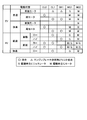
- FIG. 3 is a diagram illustrating an operation engagement table of the hybrid vehicle drive device according to the embodiment.
- FIG. 4 is a collinear diagram related to the single motor EV mode.
- FIG. 5 is a collinear diagram related to the both-motor EV mode in which the differential of the second planetary gear mechanism is restricted.
- FIG. 6 is a collinear diagram related to the both-motor EV mode in which the rotation of the first planetary gear mechanism is locked.
- FIG. 7 is a collinear diagram related to the HV traveling mode in the low state.
- FIG. 8 is a collinear diagram related to the HV driving mode in the high state.
- FIG. 9 is a diagram illustrating theoretical transmission efficiency lines according to the embodiment.
- FIG. 10 is a flowchart according to the engine start control of the embodiment.
- FIG. 11 is a time chart according to the engine start control of the embodiment.
- FIG. 12 is a skeleton diagram of the vehicle according to the first modification example of the embodiment.
- FIG. 13 is a skeleton diagram of a vehicle according to a second modification example of the embodiment.
- FIG. 14 is a skeleton diagram of a vehicle according to a third modification example of the embodiment.
- FIG. 15 is a skeleton diagram of a vehicle according to a fourth modification example of the embodiment.
- FIG. 1 is a skeleton diagram of a vehicle according to an embodiment of the present invention
- FIG. 2 is an input / output relationship diagram of the vehicle according to the embodiment.
- the vehicle 100 is a hybrid vehicle having the engine 1, the first rotating electrical machine MG1, and the second rotating electrical machine MG2 as power sources.
- Vehicle 100 may be a plug-in hybrid vehicle that can be charged by an external power source.
- the vehicle 100 includes an engine 1, a first planetary gear mechanism 10, a second planetary gear mechanism 20, a first rotating electrical machine MG1, a second rotating electrical machine MG2, a differential clutch CL0, a speed change.
- Part clutch CL1, transmission part brake BK1, HV_ECU50, MG_ECU60, and engine_ECU70 are comprised.
- the hybrid vehicle drive device 1-1 includes the first planetary gear mechanism 10, the second planetary gear mechanism 20, and the differential clutch CL0.
- the hybrid vehicle drive device 1-1 may further include a control device such as each ECU 50, 60, 70, a transmission clutch CL1, a transmission brake BK1, and the like.
- the hybrid vehicle drive device 1-1 can be applied to an FF (front engine front wheel drive) vehicle, an RR (rear engine rear wheel drive) vehicle, or the like.
- the hybrid vehicle drive device 1-1 is mounted on the vehicle 100 such that the axial direction is the vehicle width direction, for example.
- a transmission unit is configured including the first planetary gear mechanism 10, the transmission unit clutch CL1, and the transmission unit brake BK1. Further, a differential portion is configured including the second planetary gear mechanism 20 and the differential portion clutch CL0.
- the engine 1 converts the combustion energy of the fuel into a rotary motion of the output shaft and outputs it.
- the output shaft of the engine 1 is connected to the input shaft 2.
- the input shaft 2 is an input shaft of the power transmission device.
- the power transmission device includes a first rotary electric machine MG1, a second rotary electric machine MG2, clutches CL0 and CL1, a transmission brake BK1, a differential device 30 and the like.
- the input shaft 2 is arranged coaxially with the output shaft of the engine 1 and on an extension line of the output shaft.
- the input shaft 2 is connected to the first carrier 14 of the first planetary gear mechanism 10.
- the first planetary gear mechanism 10 of the present embodiment is connected to the engine 1 and corresponds to a power transmission mechanism that can output by shifting the rotation of the engine 1.
- the first planetary gear mechanism 10 which is a differential mechanism is shown as an example of a power transmission mechanism.
- the first planetary gear mechanism 10 is mounted on the vehicle 100 as a first differential mechanism.
- the first planetary gear mechanism 10 is an input-side differential mechanism that is disposed closer to the engine 1 than the second planetary gear mechanism 20.
- the first planetary gear mechanism 10 is a single pinion type and includes a first sun gear 11, a first pinion gear 12, a first ring gear 13, and a first carrier 14.
- the hybrid vehicle drive device 1-1 is mounted on the vehicle 100 such that the axial direction is the vehicle width direction, for example.
- the first ring gear 13 is coaxial with the first sun gear 11 and is disposed on the radially outer side of the first sun gear 11.
- the first pinion gear 12 is disposed between the first sun gear 11 and the first ring gear 13 and meshes with the first sun gear 11 and the first ring gear 13, respectively.
- the first pinion gear 12 is rotatably supported by the first carrier 14.
- the first carrier 14 is connected to the input shaft 2 and rotates integrally with the input shaft 2. Therefore, the first pinion gear 12 can rotate (revolve) together with the input shaft 2 around the central axis of the input shaft 2 and is supported by the first carrier 14 and rotated around the central axis of the first pinion gear 12 ( Rotation) is possible.
- the transmission clutch CL1 is a clutch device capable of connecting the first sun gear 11 and the first carrier 14.
- the transmission clutch CL1 can be, for example, a friction engagement clutch, but is not limited thereto, and a known clutch device such as a meshing clutch may be used as the transmission clutch CL1.
- the transmission clutch CL1 is engaged or released by being controlled by, for example, hydraulic pressure.
- the fully engaged transmission portion clutch CL1 can connect the first sun gear 11 and the first carrier 14 and rotate the first sun gear 11 and the first carrier 14 together.
- the disengaged transmission clutch CL1 separates the first sun gear 11 and the first carrier 14 and allows relative rotation between the first sun gear 11 and the first carrier 14. Note that the transmission clutch CL1 can be controlled to a half-engaged state.
- the transmission brake BK1 is a brake device that can regulate the rotation of the first sun gear 11.
- the transmission brake BK1 has an engagement element connected to the first sun gear 11 and an engagement element connected to the vehicle body side, for example, a case of the power transmission device.
- the transmission unit brake BK1 can be a friction engagement type clutch device similar to the transmission unit clutch CL1, but is not limited thereto, and a known clutch device such as a meshing clutch is used as the transmission unit brake BK1. May be.
- the transmission brake BK1 is engaged or released by being controlled by, for example, hydraulic pressure.
- the fully engaged transmission portion brake BK1 connects the first sun gear 11 and the vehicle body side and can regulate the rotation of the first sun gear 11.
- the opened transmission unit brake BK1 separates the first sun gear 11 from the vehicle body side and allows the first sun gear 11 to rotate.
- the transmission brake BK1 can be controlled to a half-engaged state.
- the second planetary gear mechanism 20 of the present embodiment corresponds to a differential mechanism that connects the first planetary gear mechanism 10 and the drive wheel 32.
- the second planetary gear mechanism 20 is mounted on the vehicle 100 as a second differential mechanism.
- the second planetary gear mechanism 20 is an output-side differential mechanism that is disposed closer to the drive wheel 32 than the first planetary gear mechanism 10.
- the second planetary gear mechanism 20 is a single pinion type and includes a second sun gear 21, a second pinion gear 22, a second ring gear 23, and a second carrier 24.
- the second planetary gear mechanism 20 is disposed coaxially with the first planetary gear mechanism 10 and faces the engine 1 with the first planetary gear mechanism 10 interposed therebetween.
- the second ring gear 23 is coaxial with the second sun gear 21 and is disposed on the radially outer side of the second sun gear 21.
- the second pinion gear 22 is disposed between the second sun gear 21 and the second ring gear 23 and meshes with the second sun gear 21 and the second ring gear 23, respectively.
- the second pinion gear 22 is rotatably supported by the second carrier 24.
- the second carrier 24 is connected to the first ring gear 13 and rotates integrally with the first ring gear 13. Therefore, the second pinion gear 22 can rotate (revolve) around the central axis of the input shaft 2 together with the second carrier 24, and is supported by the second carrier 24 and rotates around the central axis of the second pinion gear 22. (Rotation) is possible.
- the first ring gear 13 is an output element of the first planetary gear mechanism 10, and can output the rotation input from the engine 1 to the first planetary gear mechanism 10 to the second carrier 24.
- the second carrier 24 corresponds to the first rotating element connected to the output element of the first planetary gear mechanism 10.
- the second sun gear 21 is connected to the rotary shaft 33 of the first rotary electric machine MG1.
- the rotating shaft 33 of the first rotating electrical machine MG1 is disposed coaxially with the input shaft 2 and rotates integrally with the second sun gear 21.
- the second sun gear 21 corresponds to a second rotating element connected to the first rotating electrical machine MG1.
- a counter drive gear 25 is connected to the second ring gear 23.
- the counter drive gear 25 is an output gear that rotates integrally with the second ring gear 23.
- the second ring gear 23 corresponds to the third rotating element connected to the second rotating electrical machine MG ⁇ b> 2 and the drive wheel 32.
- the second ring gear 23 is an output element that can output the rotation input from the first rotating electrical machine MG ⁇ b> 1 or the first planetary gear mechanism 10 to the drive wheels 32.
- the differential clutch CL0 of this embodiment corresponds to a regulating device that switches between a state in which the differential of the second planetary gear mechanism 20 is regulated and a state in which the differential of the second planetary gear mechanism 20 is allowed.
- the differential clutch CL ⁇ b> 0 is a clutch device that can connect the second sun gear 21 and the second carrier 24.
- the differential clutch CL0 can be, for example, a friction engagement clutch, but is not limited thereto, and a known clutch device such as a meshing clutch may be used as the differential clutch CL0.
- the differential clutch CL0 is engaged or released by being controlled by, for example, hydraulic pressure.
- the fully engaged differential clutch CL0 can connect the second sun gear 21 and the second carrier 24 and rotate the second sun gear 21 and the second carrier 24 together.
- the fully engaged differential clutch CL0 regulates differential operation of the second planetary gear mechanism 20.
- the differential clutch CL0 in the opened state disconnects the second sun gear 21 and the second carrier 24 and allows relative rotation between the second sun gear 21 and the second carrier 24. That is, the differential clutch CL0 in the released state permits the differential operation of the second planetary gear mechanism 20.
- the differential clutch CL0 can be controlled to a half-engaged state.
- the counter drive gear 25 is meshed with the counter driven gear 26.
- the counter driven gear 26 is connected to a drive pinion gear 28 via a counter shaft 27.
- the counter driven gear 26 and the drive pinion gear 28 rotate integrally.
- the counter driven gear 26 is engaged with a reduction gear 35.
- the reduction gear 35 is connected to the rotating shaft 34 of the second rotating electrical machine MG2. That is, the rotation of the second rotating electrical machine MG ⁇ b> 2 is transmitted to the counter driven gear 26 via the reduction gear 35.
- the reduction gear 35 has a smaller diameter than the counter driven gear 26, and reduces the rotation of the second rotating electrical machine MG ⁇ b> 2 and transmits it to the counter driven gear 26.
- the drive pinion gear 28 meshes with the diff ring gear 29 of the differential device 30.
- the differential device 30 is connected to drive wheels 32 via left and right drive shafts 31.
- the second ring gear 23 is connected to the drive wheel 32 via a counter drive gear 25, a counter driven gear 26, a drive pinion gear 28, a differential device 30 and a drive shaft 31.
- the second rotating electrical machine MG2 is connected to the power transmission path between the second ring gear 23 and the drive wheel 32, and can transmit power to the second ring gear 23 and the drive wheel 32, respectively. .
- the first rotating electrical machine MG1 and the second rotating electrical machine MG2 each have a function as a motor (electric motor) and a function as a generator.
- the first rotating electrical machine MG1 and the second rotating electrical machine MG2 are connected to a battery via an inverter.
- the first rotating electrical machine MG1 and the second rotating electrical machine MG2 can convert the electric power supplied from the battery into mechanical power and output it, and are driven by the input power to convert the mechanical power into electric power. Can be converted.
- the electric power generated by the rotating electrical machines MG1 and MG2 can be stored in the battery.
- an AC synchronous motor generator can be used as the first rotating electrical machine MG1 and the second rotating electrical machine MG2.
- the transmission unit brake BK1, the transmission unit clutch CL1, the first planetary gear mechanism 10, the counter drive gear 25, and the second planetary gear mechanism are arranged in order from the side closer to the engine 1 coaxially with the engine 1. 20 and the first rotating electrical machine MG1 are arranged.
- the hybrid vehicle drive device 1-1 of the present embodiment is a multi-shaft type in which the input shaft 2 and the rotation shaft 34 of the second rotating electrical machine MG2 are arranged on different axes.
- the vehicle 100 includes an HV_ECU 50, an MG_ECU 60, and an engine_ECU 70.
- Each ECU 50, 60, 70 is an electronic control unit having a computer.
- the HV_ECU 50 has a function of integrally controlling the entire vehicle 100.
- MG_ECU 60 and engine_ECU 70 are electrically connected to HV_ECU 50.
- MG_ECU 60 can control the first rotating electrical machine MG1 and the second rotating electrical machine MG2. For example, the MG_ECU 60 adjusts the current value supplied to the first rotating electrical machine MG1, controls the output torque of the first rotating electrical machine MG1, and adjusts the current value supplied to the second rotating electrical machine MG2. The output torque of the second rotating electrical machine MG2 can be controlled.
- Engine_ECU 70 can control engine 1.
- the engine_ECU 70 can control, for example, the opening degree of the electronic throttle valve of the engine 1, perform ignition control of the engine by outputting an ignition signal, and control of fuel injection to the engine 1.
- the engine_ECU 70 can control the output torque of the engine 1 by electronic throttle valve opening control, injection control, ignition control, and the like.
- the HV_ECU 50 is connected to a vehicle speed sensor, an accelerator opening sensor, an MG1 rotational speed sensor, an MG2 rotational speed sensor, an output shaft rotational speed sensor, a battery sensor, and the like. With these sensors, the HV_ECU 50 obtains the vehicle speed, the accelerator opening, the rotational speed of the first rotating electrical machine MG1, the rotational speed of the second rotating electrical machine MG2, the rotational speed of the output shaft of the power transmission device, the battery state SOC, and the like. Can do.
- the HV_ECU 50 can calculate the required driving force, required power, required torque, and the like for the vehicle 100 based on the acquired information.
- the HV_ECU 50 also describes the output torque of the first rotating electrical machine MG1 (hereinafter also referred to as “MG1 torque”) and the output torque of the second rotating electrical machine MG2 (hereinafter referred to as “MG2 torque”) based on the calculated request value.
- MG1 torque the output torque of the second rotating electrical machine MG2
- engine torque the output torque of the engine 1
- the HV_ECU 50 outputs the MG1 torque command value and the MG2 torque command value to the MG_ECU 60. Further, the HV_ECU 50 outputs an engine torque command value to the engine_ECU 70.
- the HV_ECU 50 controls the differential clutch CL0, the transmission clutch CL1, and the transmission brake BK1, respectively, based on a travel mode described later.
- the HV_ECU 50 outputs a command value (PbCL0) for supply hydraulic pressure to the differential clutch CL0, a command value (PbCL1) for supply hydraulic pressure to the transmission clutch CL1, and a command value (PbBK1) for supply hydraulic pressure to the transmission brake BK1.
- a hydraulic control device (not shown) controls the hydraulic pressure supplied to the differential clutch CL0, the transmission clutch CL1, and the transmission brake BK1 according to the command values PbCL0, PbCL1, PbBK1, respectively.
- FIG. 3 is a diagram showing an operation engagement table of the hybrid vehicle drive device 1-1 according to the present embodiment.
- the vehicle 100 can selectively execute hybrid (HV) traveling or EV traveling.
- the HV travel is a travel mode in which the vehicle 100 travels using the engine 1 as a power source.
- the second rotating electrical machine MG2 may be used as a power source.
- the hybrid vehicle drive device 1-1 includes, as the EV travel mode, the single motor EV mode in which the vehicle 100 travels using the second rotating electrical machine MG2 as a single power source, the first rotating electrical machine MG1, and the second rotating electrical machine MG1. It has a dual motor EV mode in which vehicle 100 travels using rotating electric machine MG2 as a power source.
- FIG. 4 is a collinear diagram related to the single motor EV mode.
- reference numerals S1, C1, and R1 indicate the first sun gear 11, the first carrier 14, and the first ring gear 13, respectively.
- Reference numerals S2, C2, and R2 indicate the second sun gear 21 and the second carrier 24, respectively.
- the 2nd ring gear 23 is shown.
- the differential clutch CL0, the transmission clutch CL1, and the transmission brake BK1 are released.
- the first sun gear 11 is allowed to rotate when the transmission unit brake BK1 is released, and the first planetary gear mechanism 10 can be differentially operated when the transmission unit clutch CL1 is opened.
- the second planetary gear mechanism 20 can be differentially operated.
- the HV_ECU 50 causes the second rotating electrical machine MG2 to output a positive torque via the MG_ECU 60 to cause the vehicle 100 to generate a driving force in the forward direction.
- the second ring gear 23 rotates forward in conjunction with the rotation of the drive wheel 32.
- the normal rotation is the rotation direction of the second ring gear 23 when the vehicle 100 moves forward.
- the HV_ECU 50 operates the first rotating electrical machine MG1 as a generator to reduce drag loss. Specifically, the HV_ECU 50 generates a power by applying a slight torque to the first rotating electrical machine MG1, and sets the rotational speed of the first rotating electrical machine MG1 to 0. Thereby, the drag loss of the first rotating electrical machine MG1 can be reduced.
- the first ring gear 13 rotates along with the second carrier 24 and rotates forward.
- the transmission clutch CL1 and the transmission brake BK1 are in a neutral state, the engine 1 is not rotated and the first carrier 14 stops rotating. Therefore, it is possible to increase the amount of regeneration.
- the first sun gear 11 idles and rotates negatively.
- the neutral state of the first planetary gear mechanism 10 is a state in which no power is transmitted between the first ring gear 13 and the first carrier 14, that is, the engine 1 and the second planetary gear mechanism 20 are disconnected. , It is in a blocked state.
- the first planetary gear mechanism 10 is connected to connect the engine 1 and the second planetary gear mechanism 20 when at least one of the transmission clutch CL1 and the transmission brake BK1 is engaged.
- the transmission clutch CL1 and the transmission brake BK1 each function as a switching device that switches the first planetary gear mechanism 10 between a connected state and a neutral state.
- the battery When running in the single motor EV mode, the battery may be fully charged and regenerative energy may not be obtained. In this case, it is conceivable to use an engine brake together.
- the engine 1 By engaging the transmission clutch CL1 or the transmission brake BK1, the engine 1 can be connected to the drive wheels 32 and the engine brake can be applied to the drive wheels 32.
- the transmission clutch CL1 or the transmission brake BK1 is engaged in the single motor EV mode, the engine 1 is rotated and the engine speed is increased by the first rotating electrical machine MG1.
- the brake state can be set.
- the HV_ECU 50 locks the rotation of the first planetary gear mechanism 10 or restricts the differential of the second planetary gear mechanism 20.
- the HV_ECU 50 regulates the differential of the second planetary gear mechanism 20 by engaging the differential clutch CL0.
- the transmission clutch CL1 and the transmission brake BK1 are released.
- the both-motor EV mode in which the differential clutch CL0 is engaged and the transmission clutch CL1 and the transmission brake BK1 are released corresponds to the predetermined mode.
- FIG. 5 is a collinear diagram related to the both-motor EV mode in which the differential of the second planetary gear mechanism 20 is restricted. Engagement of the differential clutch CL0 restricts the relative rotation of each rotating element of the second planetary gear mechanism 20, and the second sun gear 21, the second carrier 24, and the second ring gear 23 rotate at the same rotational speed. To do.
- the HV_ECU 50 causes the first rotary electric machine MG1 and the second rotary electric machine MG2 to output driving driving torque, respectively.
- the first rotating electrical machine MG1 can output a positive torque from the second ring gear 23 by outputting a positive torque during forward movement and rotating forward.
- the first rotating electrical machine MG1 can output negative torque from the second ring gear 23 by outputting negative torque and performing negative rotation.
- the dual motor EV mode in which the differential of the second planetary gear mechanism 20 is restricted, the first planetary gear mechanism 10 is in a neutral state. As a result, the engine speed can be reduced to zero. Since the neutral state is realized by releasing the transmission clutch CL1 and the transmission brake BK1, a dedicated clutch for engine disconnection is unnecessary.
- FIG. 6 is a collinear diagram related to the both-motor EV mode in which the rotation of the first planetary gear mechanism 10 is locked.
- the differential of the first planetary gear mechanism 10 is restricted when the transmission clutch CL1 is engaged, and the rotation of the first sun gear 11 is restricted when the transmission brake BK1 is engaged. Accordingly, the rotation of all the rotating elements of the first planetary gear mechanism 10 is stopped.
- the second carrier 24 connected thereto is locked at 0 rotation.
- the HV_ECU 50 causes the first rotary electric machine MG1 and the second rotary electric machine MG2 to output driving driving torque, respectively. Since the rotation of the second carrier 24 is restricted, the second carrier 24 can take a reaction force against the torque of the first rotating electrical machine MG ⁇ b> 1 and output the torque of the first rotating electrical machine MG ⁇ b> 1 from the second ring gear 23.
- the first rotating electrical machine MG1 can output a positive torque from the second ring gear 23 by outputting a negative torque and rotating negatively when moving forward.
- the first rotating electrical machine MG1 can output a negative torque from the second ring gear 23 by outputting a positive torque and rotating forward.
- FIG. 7 is a collinear diagram related to the HV driving mode in the low state (hereinafter also referred to as “HV low mode”), and FIG. 8 is also referred to as the HV driving mode in the high state (hereinafter referred to as “HV high mode”).
- HV low mode the HV driving mode in the low state
- HV high mode the HV driving mode in the high state
- the HV_ECU 50 engages the transmission clutch CL1 and releases the transmission brake BK1.
- the transmission clutch CL1 is engaged, the differential of the first planetary gear mechanism 10 is restricted, and the rotary elements 11, 13, and 14 rotate integrally. Accordingly, the rotation of the engine 1 is not accelerated or decelerated and is transmitted from the first ring gear 13 to the second carrier 24 at a constant speed.
- the HV_ECU 50 releases the transmission clutch CL1 and engages the transmission brake BK1.
- the transmission brake BK1 is engaged, the rotation of the first sun gear 11 is restricted. Therefore, the first planetary gear mechanism 10 enters an overdrive (OD) state in which the rotation of the engine 1 input to the first carrier 14 is increased and output from the first ring gear 13.
- the first planetary gear mechanism 10 can increase the rotation speed of the engine 1 and output it.
- the gear ratio during overdrive can be set to 0.7, for example.
- the HV_ECU 50 selects the HV high mode at a high vehicle speed, and selects the HV low mode at a medium to low vehicle speed.
- the HV_ECU 50 selects the HV high mode at a high vehicle speed, and selects the HV low mode at a medium to low vehicle speed.
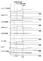
- FIG. 9 is a diagram showing a theoretical transmission efficiency line according to the present embodiment.
- the horizontal axis represents the gear ratio
- the vertical axis represents the theoretical transmission efficiency.
- the transmission ratio is a ratio (reduction ratio) of the input side rotational speed to the output side rotational speed of the planetary gear mechanisms 10 and 20, for example, the rotation of the first carrier 14 with respect to the rotational speed of the second ring gear 23. Indicates the ratio of numbers.
- the left side is the high gear side with a small gear ratio
- the right side is the low gear side with a large gear ratio.
- the theoretical transmission efficiency is 1.0 when the power input to the planetary gear mechanisms 10 and 20 is all transmitted to the counter drive gear 25 by mechanical transmission without passing through an electrical path.
- the curve shown in FIG. 9 is a theoretical transmission efficiency line in the HV traveling mode when the HV high mode and the HV low mode are appropriately switched.
- a high-efficiency mode is selected from the HV high mode and the HV low mode at the same gear ratio.
- the right side is the theoretical transmission efficiency line in the HV low mode, and the left side is the theoretical transmission efficiency line in the HV high mode.
- the transmission efficiency in the HV low mode becomes the maximum efficiency at the gear ratio ⁇ 1.
- the rotational speed of the first rotating electrical machine MG1 (second sun gear 21) is zero.
- the speed ratio ⁇ 1 is a speed ratio on the overdrive side, that is, a speed ratio smaller than 1.
- the speed ratio ⁇ 1 is also referred to as “first mechanical transmission speed ratio ⁇ 1”.
- the theoretical transmission efficiency of the HV high mode is the maximum efficiency at the gear ratio ⁇ 2.
- the rotational speed of the first rotating electrical machine MG1 (second sun gear 21) becomes 0 at the gear ratio ⁇ 2, and power can be transmitted from the engine 1 to the counter drive gear 25 only by transmission of mechanical power.
- the speed ratio ⁇ 2 is a speed ratio on the high gear side with respect to the first machine transmission speed ratio ⁇ 1.
- the speed ratio ⁇ 2 is also referred to as “second mechanical transmission speed ratio ⁇ 2”.
- the theoretical transmission efficiency in the HV traveling mode decreases as the gear ratio becomes a value on the low gear side from the first machine transmission gear ratio ⁇ 1. Further, the theoretical transmission efficiency in the HV traveling mode decreases as the gear ratio becomes a value on the high gear side with respect to the second machine transmission gear ratio ⁇ 2.
- the theoretical transmission efficiency in the HV traveling mode is curved to the low efficiency side in the speed ratio region between the first machine transmission speed ratio ⁇ 1 and the second machine transmission speed ratio ⁇ 2.
- the hybrid vehicle drive device 1-1 has two mechanical points on the high gear side with respect to the gear ratio 1.
- the hybrid vehicle drive device 1-1 includes a transmission unit including the first planetary gear mechanism 10, the transmission unit clutch CL1, and the transmission unit brake BK1, so that the engine 1 is directly connected to the second carrier 24.
- the second mechanical point (second machine transmission speed ratio ⁇ 2) can be generated on the high gear side from the mechanical point (first machine transmission speed ratio ⁇ 1). Therefore, transmission efficiency during high gear operation can be improved. That is, it is possible to realize a hybrid system that can improve fuel efficiency by improving transmission efficiency during high-speed traveling.
- the second planetary gear mechanism 20 may be in a non-differential locked state. In this case, the differential clutch CL0 is engaged. When the differential of the second planetary gear mechanism 20 is restricted, the second sun gear 21, the second carrier 24, and the second ring gear 23 rotate integrally. For this reason, there is no need to receive a reaction force from the first rotating electrical machine MG1 for power transmission from the second carrier 24 to the second ring gear 23, and HV traveling can be performed without generating an electric path. Even in HV traveling with the second planetary gear mechanism 20 in a non-differential state, the first planetary gear mechanism 10 can be in the high state at high vehicle speeds, and the first planetary gear mechanism 10 can be in the low state at medium and low vehicle speeds. . Thus, by traveling by switching between the HV high mode and the HV low mode, the movement of the engine operating point is reduced and the reduction in fuel consumption is suppressed.
- the first rotating electrical machine MG1 can be used for both assist (motor) and regeneration (generator). Therefore, in the HV traveling mode in which the second planetary gear mechanism 20 is non-differential, the HV_ECU 50 can selectively use both the rotary electric machines MG1 and MG2 for assist and for regeneration as necessary.
- HV_ECU 50 performs negative rotation using the first rotating electrical machine MG1 as a generator and the second rotating electrical machine MG2 as a motor during reverse travel in the HV travel mode.
- the HV_ECU 50 may cause the second rotating electrical machine MG2 to rotate negatively independently and travel backward, and the vehicle is driven by both the first rotating electrical machine MG1 and the second rotating electrical machine MG2. 100 may be reversed.
- the HV_ECU 50 executes coordinated shift control for simultaneously shifting the first planetary gear mechanism 10 and the second planetary gear mechanism 20 when switching between the HV high mode and the HV low mode.
- the HV_ECU 50 increases one gear ratio of the first planetary gear mechanism 10 and the second planetary gear mechanism 20 and decreases the other gear ratio.
- HV_ECU 50 changes the gear ratio of second planetary gear mechanism 20 to the high gear side in synchronization with the mode switching when switching from the HV high mode to the HV low mode.
- the discontinuous change of the gear ratio in the whole from the engine 1 of the vehicle 100 to the drive wheel 32 can be suppressed or reduced, and the degree of the change of the gear ratio can be reduced.
- the HV_ECU 50 shifts the first planetary gear mechanism 10 and the second planetary gear mechanism 20 in a coordinated manner so as to continuously change the gear ratio of the entire vehicle 100 to the low side.
- the HV_ECU 50 when switching from the HV low mode to the HV high mode, changes the gear ratio of the second planetary gear mechanism 20 to the low gear side in synchronization with the mode switching. Thereby, the discontinuous change of the gear ratio in the entire vehicle 100 can be suppressed or reduced, and the degree of change of the gear ratio can be reduced.
- the HV_ECU 50 shifts the first planetary gear mechanism 10 and the second planetary gear mechanism 20 in a coordinated manner so as to continuously change the gear ratio of the entire vehicle 100 to the high side.
- the adjustment of the gear ratio of the second planetary gear mechanism 20 is performed, for example, by controlling the rotational speed of the first rotating electrical machine MG1.
- the HV_ECU 50 controls the first rotating electrical machine MG1 so as to change the speed ratio between the input shaft 2 and the counter drive gear 25 steplessly.
- the entire planetary gear mechanisms 10 and 20, the first rotating electrical machine MG1, the transmission clutch CL1 and the transmission brake BK1, that is, the transmission including the differential and the transmission operates as an electric continuously variable transmission. .
- the HV_ECU 50 starts the stopped engine 1 when shifting from the EV travel mode to the HV travel mode.
- the HV_ECU 50 starts the engine 1 by rotating the engine 1 with the first rotating electrical machine MG1.
- the HV_ECU 50 can switch the first planetary gear mechanism 10 from the neutral state to the connected state and start the engine 1 while maintaining both motor driving.
- FIG. 10 is a flowchart according to the engine start control of the present embodiment
- FIG. 11 is a time chart according to the engine start control of the present embodiment.
- (a) is the engine speed
- (b) is the MG1 torque
- (c) is the speed of the first rotating electrical machine MG1
- (d) is the MG2 torque
- (e) is the rotating speed of the second rotating electrical machine MG2.
- (F) indicates the hydraulic pressure of the transmission clutch CL1
- (g) indicates the state of charge SOC
- (h) indicates the accelerator opening.
- the control flow shown in FIG. 10 is executed during traveling in the EV traveling mode, for example.
- step S10 the HV_ECU 50 determines whether or not the state of charge SOC is less than the threshold value Sf.
- the threshold value Sf is used to determine, for example, whether the engine 1 needs to be started and the battery needs to be charged.
- step S10-Y if it is determined that the state of charge SOC is less than the threshold value Sf (step S10-Y), the process proceeds to step S20, and if not (step S10-N), the process proceeds to step S80.
- the state of charge SOC becomes less than the threshold value Sf at time t1, and an affirmative determination is made in step S10.
- step S20 the HV_ECU 50 determines whether or not it is the single motor EV mode by the second rotating electrical machine MG2.
- the single motor EV mode by the second rotating electrical machine MG2 is selected.
- the both-motor EV mode is selected.
- step S30 the HV_ECU 50 switches the engagement of the transmission clutch CL1.
- the transmission clutch CL1 In the single motor EV mode, in addition to the case where both the transmission clutch CL1 and the transmission brake BK1 are released, the transmission clutch CL1 is engaged when the transmission clutch CL1 is engaged and the transmission brake BK1 is released. May be released and the transmission brake BK1 may be engaged.
- the HV_ECU 50 switches to a state where the transmission clutch CL1 is engaged and the transmission brake BK1 is released.
- step S40 the HV_ECU 50 performs engine start control by controlling the rotational speed of the first rotating electrical machine MG1.
- the engine 1 is connected to the first rotating electrical machine MG1, the second rotating electrical machine MG2, and the drive wheels 32, and is brought into a rotated state.
- the HV_ECU 50 sets the rotation speed of the second carrier 24 to 0 by controlling the rotation speed of the first rotating electrical machine MG1, and engages the transmission clutch CL1.
- the HV_ECU 50 increases the engine speed by controlling the rotational speed of the first rotating electrical machine MG1 when the transmission clutch CL1 is engaged.
- the HV_ECU 50 supplies fuel to the engine 1 and starts the engine 1 by ignition control.
- the HV_ECU 50 can smoothly increase the hydraulic pressure supplied to the transmission clutch CL1 while rotating the second carrier 24 to smoothly engage the transmission clutch CL1. .
- the HV_ECU 50 increases the engine speed by controlling the rotational speed of the first rotating electrical machine MG1 after the transmission clutch CL1 is completely engaged or simultaneously with increasing the clutch torque capacity of the transmission clutch CL1.
- step S50 the HV_ECU 50 performs reaction force torque control of the second rotating electrical machine MG2.
- the starting reaction torque is applied to the second ring gear 23 by the MG1 torque.
- This starting reaction force torque is a torque in the negative direction and is a torque that reduces the driving force of the vehicle 100.
- the HV_ECU 50 increases the torque of the second rotating electrical machine MG2 in the positive direction so as to suppress the loss of driving force due to the starting reaction force torque. That is, in the reaction force torque control, the second rotating electrical machine MG2 outputs a cancel torque for canceling the starting reaction force torque. As a result, a decrease in drivability due to torque fluctuation at the start of the engine is suppressed.
- step S60 the HV_ECU 50 switches the engagement of the transmission clutch CL1.
- the transmission clutch CL1 and the transmission brake BK1 are each released.
- the HV_ECU 50 is in a state where the transmission clutch CL1 is engaged and the transmission brake BK1 is released.
- the first planetary gear mechanism 10 is in a state where the first sun gear 11, the first carrier 14, and the first ring gear 13 rotate together, that is, the engine 1 and the second carrier 24. Is connected.
- the HV_ECU 50 gradually increases the hydraulic pressure supplied to the transmission clutch CL1 to cause the transmission clutch CL1 to slip-engage (smooth engagement).
- mode switching is started at time t2, and the hydraulic pressure supplied to the transmission clutch CL1 begins to rise.
- the transmission clutch CL1 is engaged, and the engine speed starts to increase.
- the engine speed increases to a predetermined speed, and ignition of the engine 1 is started. Since the engine torque starts to be output, the MG1 torque is switched from the positive torque for driving to the negative torque for receiving the reaction force.
- step S60 is executed, the process proceeds to step S70.
- step S70 the HV_ECU 50 performs MG2 torque compensation control.
- the transmission clutch CL1 is engaged in step S60, the inertia torque for increasing the engine speed is consumed.
- the HV_ECU 50 compensates the torque drop for the inertia with the MG2 torque, and suppresses the torque drop of the output. In addition, you may make it compensate the torque fall for an inertia with the torque of both the 1st rotary electric machine MG1 and the 2nd rotary electric machine MG2.
- step S70 is executed, the control flow ends.
- step S80 the HV_ECU 50 continues the motor travel. Since HV_ECU 50 does not require engine start, HV_ECU 50 continues traveling in the EV traveling mode. When step S80 is executed, this control flow ends.
- the transmission unit brake BK1 may be engaged instead of engaging the transmission unit clutch CL1. Even in this case, the engine speed can be increased with the first planetary gear mechanism 10 in the connected state.
- step S60 instead of engaging the transmission clutch CL1, the transmission brake BK1 may be engaged.
- the transmission brake BK1 When the transmission brake BK1 is engaged, the first sun gear 11 can receive the reaction force and increase the engine speed.
- the HV_ECU 50 can gradually increase the engine speed by gradually increasing the hydraulic pressure supplied to the transmission brake BK1.
- Whether the transmission clutch CL1 or the transmission brake BK1 is engaged when the engine is started can be determined based on, for example, the amount of increase in the engine speed caused by the engagement. What is necessary is just to engage what can satisfy the increase amount of the engine speed required for engine starting.
- step S60 When the engine 1 is started from the both-motor EV mode in which the rotation of the first planetary gear mechanism 10 is locked, the transmission brake BK1 may be released in step S60.
- engine start control can be performed by controlling the number of revolutions of the first rotating electrical machine MG1 as in step S40, and reaction force torque control of the second rotating electrical machine MG2 can be performed as in step S50.
- the hybrid vehicle drive device 1-1 is configured to switch between the HV high mode and the HV low mode by the transmission unit including the first planetary gear mechanism 10, the transmission unit clutch CL1, and the transmission unit brake BK1. Can be switched, and the transmission efficiency of the vehicle 100 can be improved. Further, a second planetary gear mechanism 20 as a differential unit is connected in series with the subsequent stage of the transmission unit. Since the first planetary gear mechanism 10 is overdriven, there is an advantage that the first rotating electrical machine MG1 does not have to be greatly increased in torque.
- the differential of the second planetary gear mechanism 20 is restricted, and traveling in the both-motor EV mode can be performed.
- the both-motor EV mode in which the differential clutch CL0 is engaged, the engine 1 can be started with both the motors being driven. Therefore, it is not necessary to perform engine start control by controlling the number of revolutions of the first rotating electrical machine MG1, and the EV travel range can be expanded.
- the MG1 torque is changed from a negative torque for driving to a positive torque for cranking. Can be switched to.
- the MG2 torque In order to compensate for the MG1 torque loss with the MG2 torque, the MG2 torque needs to have a margin for the compensation torque. On the other hand, in the both-motor EV mode in which the differential clutch CL0 is engaged, the MG1 torque is not lost, so that the EV travel range can be extended to the high output side.
- the engine 1 can be started without switching the differential portion such as reversal of the MG1 torque, a decrease in the output torque can be suppressed only by increasing the MG2 torque, and the switching shock is reduced.
- the reduction ratio of the second rotating electrical machine MG2 can be increased. Further, a compact arrangement can be realized by the FF or RR layout.
- the transmission unit including the first planetary gear mechanism 10 is provided closer to the engine 1 than the second planetary gear mechanism 20, the transmission as a whole is changed.
- the specific width becomes wide. Therefore, the gear ratio from the differential part to the wheel can be increased.
- the engine speed is maintained at substantially zero by releasing the transmission clutch CL1 and the transmission brake BK1 of the transmission to neutral. Therefore, a dedicated clutch for engine disconnection is unnecessary.
- the HV high mode and the HV low mode can be switched by shifting the speed change unit during HV traveling. By taking two mechanical points by this shift, it is possible to suppress the occurrence of power circulation by selecting an appropriate gear ratio during high-speed travel. Further, by simultaneously shifting the second planetary gear mechanism 20 at the time of shifting of the transmission unit, it is possible to suppress a rapid change in the gear ratio.
- the differential clutch CL0 of the present embodiment connects the second sun gear 21 and the second carrier 24, but is not limited to this.
- the differential clutch CL0 only needs to be capable of regulating the differential of the second planetary gear mechanism 20 by connecting the rotating elements 21, 23, 24 of the second planetary gear mechanism 20 to each other.
- the transmission clutch CL1 of the present embodiment connects the first sun gear 11 and the first carrier 14, but is not limited to this.
- the transmission clutch CL1 only needs to be capable of regulating the differential of the first planetary gear mechanism 10 by connecting the rotating elements 11, 13, and 14 of the first planetary gear mechanism 10 to each other.
- the transmission brake BK1 is not limited to one that restricts the rotation of the first sun gear 11.
- the transmission brake BK ⁇ b> 1 may restrict the rotation of the other rotating elements of the first planetary gear mechanism 10.
- the power transmission mechanism and the differential mechanism are the planetary gear mechanisms 10 and 20, respectively, but are not limited thereto.
- the power transmission mechanism may be another known differential mechanism or a gear mechanism that can be switched to a plurality of gear ratios. Further, another known differential mechanism may be used as the output side differential mechanism.
- the power transmission mechanism may be, for example, a twin clutch type.
- the power transmission mechanism includes a first transmission unit that transmits the rotation of the engine 1 to the second planetary gear mechanism 20 at a first gear ratio via the first clutch, and a second transmission via the second clutch.
- You may have a 2nd transmission part which transmits rotation of the engine 1 to the 2nd planetary gear mechanism 20 with a gear ratio.
- the first gear ratio and the second gear ratio are different.
- This power transmission mechanism is in a connected state in which power can be transmitted from the engine 1 to the second planetary gear mechanism 20 by engaging either the first clutch or the second clutch. Further, the power transmission mechanism restricts the rotation of the output element by engaging both the first clutch and the second clutch.
- the power transmission mechanism is in a neutral state in which power transmission between the engine 1 and the second planetary gear mechanism 20 is impossible by opening both the first clutch and the second clutch.
- the first gear is connected to the engine 1 via a first clutch
- the second gear is connected to the engine 1 via a second clutch. Further, the number of teeth is different between the first gear and the second gear.
- the first transmission unit includes a first gear, a first clutch, and an input gear.
- the second transmission unit includes a second gear, a second clutch, and an input gear. When the first clutch is engaged, the rotation of the engine 1 is transmitted to the second planetary gear mechanism 20 by the first transmission unit at a gear ratio corresponding to the gear ratio between the first gear and the input gear.
- the first transmission unit and the second transmission unit may further include a speed change mechanism.
- the engine connected to the first planetary gear mechanism 10 is the engine 1, but another known engine may be connected to the first planetary gear mechanism 10 instead.
- FIG. 12 is a skeleton diagram of the vehicle 100 according to the first modification.
- the hybrid vehicle drive device 1-2 according to this modification is different from the hybrid vehicle drive device 1-1 of the above-described embodiment in that a differential brake BK0 is provided.
- the differential brake BK0 can regulate the rotation of the second carrier 24.
- the differential brake BK0 is, for example, a friction engagement type brake device.
- the differential brake BK0 includes an engagement element connected to the vehicle body side and an engagement element connected to the second carrier 24.
- the fully engaged differential brake BK0 connects the vehicle body side and the second carrier 24, and restricts the rotation of the second carrier 24.
- the HV_ECU 50 can realize the both-motor EV mode by engaging the differential brake BK0 instead of engaging the differential clutch CL0.
- the differential brake BK0 is released, the transmission clutch CL1 or the transmission brake BK1 is engaged, and the first rotating electrical machine Engine start control can be performed by controlling the number of revolutions of MG1.
- the first rotary electric machine MG1 can perform regeneration by engaging the differential brake BK0.
- the HV_ECU 50 can use both the rotary electric machines MG1 and MG2 for both assisting and regenerating as needed.
- a one-way clutch F0 may be provided.
- the one-way clutch F0 can regulate the rotation of the second carrier 24.
- the one-way clutch F0 allows positive rotation of the second carrier 24 and restricts negative rotation.
- the one-way clutch F0 functions as a reaction force receiver for the output torque of the first rotating electrical machine MG1 and can output the MG1 torque to the second ring gear 23.
- the first rotating electrical machine MG1 can output a positive torque for forward drive from the second ring gear 23 by outputting a negative torque and performing a negative rotation.
- the one-way clutch F0 When the one-way clutch F0 is provided, it is not necessary to supply hydraulic pressure when starting in the both-motor EV mode. For example, when the dual motor EV mode is implemented by engaging the differential clutch CL0 and the differential brake BK0, it is necessary to supply hydraulic pressure by an electric pump or the like at the time of start. On the other hand, the one-way clutch F0 does not require hydraulic pressure, and has an advantage that it can be automatically engaged at the time of start and receive the reaction force of the first rotating electrical machine MG1.
- the second planetary gear mechanism 20 When the two-motor EV mode is performed by the differential brake BK0 or the one-way clutch F0, the second planetary gear mechanism 20 is in a differential state, and can rotate and output the rotation of the first rotating electrical machine MG1. .
- the second carrier 24 can be fixed by the differential brake BK0 or the one-way clutch F0 to drive both the first rotating electrical machine MG1 and the second rotating electrical machine MG2.
- the differential brake BK0 and the one-way clutch F0 correspond to a second regulating device that can regulate the rotation of the first rotating element of the second planetary gear mechanism 20.
- the switching means for switching to the both-motor EV mode is not limited to the differential brake BK0 or the one-way clutch F0.
- the switching means other mechanisms that can fix the second carrier 24 (first rotating element) may be used.
- FIG. 13 is a skeleton diagram of the vehicle 100 according to the second modification.
- the hybrid vehicle drive device 1-3 according to this modification differs from the hybrid vehicle drive devices 1-1 and 1-2 of the above-described embodiment and the first modification in that the differential unit is on the second axis. That is, it is arranged on the same axis as the second rotating electrical machine MG2.
- the configuration of the transmission unit can be the same as that of the transmission unit of the above embodiment and the first modification.
- the hybrid vehicle drive device 1-3 can be applied to an FF or RR layout.
- the first rotating electrical machine MG1 and the second planetary gear mechanism 40 are arranged coaxially with the second rotating electrical machine MG2.
- the drive pinion gear 28, the second rotating electrical machine MG2, the second planetary gear mechanism 40, the counter driven gear 45, the differential clutch CL0, and the differential are sequentially arranged from the side closer to the engine 1.
- a partial brake BK0 and a first rotating electrical machine MG1 are arranged.
- the second planetary gear mechanism 40 is a single pinion type, like the second planetary gear mechanism 20 of the above embodiment, and includes a second sun gear 41, a second pinion gear 42, a second ring gear 43, and a second carrier 44. .
- the counter driven gear 45 is connected to the second carrier 44.
- the counter driven gear 45 meshes with the counter drive gear 15 connected to the first ring gear 13. That is, in the hybrid vehicle drive device 1-3 according to this modification, the first ring gear 13 is an output element of the first planetary gear mechanism 10 as in the hybrid vehicle drive device 1-1 of the above embodiment.
- the second carrier 44 is the first rotating element of the second planetary gear mechanism 40.
- the differential clutch CL0 can connect the second sun gear 41 and the second carrier 44 as in the above embodiment.
- the differential brake BK0 can regulate the rotation of the second carrier 44 as in the first modification of the above embodiment.
- the hybrid vehicle drive device 1-3 may not include the differential brake BK0.
- a one-way clutch F0 that restricts the negative rotation of the second carrier 44 may be provided instead of the differential brake BK0.
- the first rotating electrical machine MG1 is connected to the first sun gear 41.
- the second ring gear 43 is connected to the rotary shaft 43 of the second rotary electric machine MG2. That is, in the second planetary gear mechanism 40, the second sun gear 41 corresponds to the second rotation element, and the second ring gear 43 corresponds to the third rotation element.
- the drive pinion gear 28 is disposed on the rotation shaft 34 of the second rotary electric machine MG2.
- the hybrid vehicle drive device 1-3 can be controlled based on the operation engagement table of the above embodiment. Further, when the differential brake BK0 or the one-way clutch F0 is provided, the same control as in the first modification of the above embodiment is possible.
- the hybrid vehicle drive device 1-3 has an advantage that the first axis coaxial with the engine 1 can be shortened in the FF layout. Further, the differential section is concentrated on the second axis.
- the drive pinion gear 28 and the diff ring gear 29 can be disposed between the second planetary gear mechanism 40 and the second rotating electrical machine MG2.
- FIG. 14 is a skeleton diagram of the vehicle 100 according to the third modification.
- the hybrid vehicle drive device 1-4 according to this modification is different from the hybrid vehicle drive devices 1-1, 1-2, and 1-3 according to the above-described embodiment and each modification in a five-axis configuration.
- the differential section and the second rotating electrical machine MG2 are arranged on the third axis.
- Connecting counter gears 16 and 46 are disposed on the second and fourth axes.
- the counter gears 16 and 46 can avoid interference between the transmission unit and the differential unit, and can make the transmission ratio and the rotation direction appropriate.
- the configuration of the transmission unit can be the same as the configuration of the transmission unit of the hybrid vehicle drive devices 1-1, 1-2, and 1-3 according to the above-described embodiments and modifications.
- the hybrid vehicle drive device 1-4 can be applied to an FF or RR layout.
- the first rotating electrical machine MG1 and the second planetary gear mechanism 40 are arranged coaxially with the second rotating electrical machine MG2.
- the second rotating electrical machine MG2 On the same axis as the second rotating electrical machine MG2, the second rotating electrical machine MG2, the drive pinion gear 28, the second planetary gear mechanism 40, the counter driven gear 45, the differential clutch CL0, and the differential are sequentially arranged from the side closer to the engine 1.
- a partial brake BK0 and a first rotating electrical machine MG1 are arranged.
- the second planetary gear mechanism 40 is a single pinion type, like the second planetary gear mechanism 20 of the above embodiment, and includes a second sun gear 41, a second pinion gear 42, a second ring gear 43, and a second carrier 44. .
- the counter driven gear 45 is connected to the second carrier 44.
- the counter driven gear 45 meshes with the counter drive gear 15 via the counter gear 16.
- the counter gear 16 has a smaller diameter than the counter drive gear 15 and the counter driven gear 45.
- the counter drive gear 15 is connected to the first ring gear 13.
- the first ring gear 13 is an output element of the first planetary gear mechanism 10 as in the hybrid vehicle drive device 1-1 of the above embodiment.
- the two carrier 44 is the first rotating element of the second planetary gear mechanism 40.
- the differential clutch CL0 can connect the second sun gear 41 and the second carrier 44 as in the above embodiment.
- the differential brake BK0 can regulate the rotation of the second carrier 44 as in the first modification of the above embodiment.
- the hybrid vehicle drive device 1-4 may not include the differential brake BK0.
- a one-way clutch F0 that restricts the negative rotation of the second carrier 44 may be provided instead of the differential brake BK0.
- the first rotating electrical machine MG1 is connected to the first sun gear 41.
- the second ring gear 43 is connected to the rotary shaft 43 of the second rotary electric machine MG2. That is, in the second planetary gear mechanism 40, the second sun gear 41 corresponds to the second rotation element, and the second ring gear 43 corresponds to the third rotation element.
- the drive pinion gear 28 is disposed on the rotation shaft 34 of the second rotary electric machine MG2.
- the drive pinion gear 28 is connected to the diff ring gear 29 via a counter gear 46.
- the counter gear 46 has a smaller diameter than the drive pinion gear 28 and the diff ring gear 29.
- the hybrid vehicle drive device 1-4 can be controlled based on the operation engagement table of the above embodiment. Further, when the differential brake BK0 or the one-way clutch F0 is provided, the same control as in the first modification of the above embodiment is possible.
- the hybrid vehicle drive device 1-4 according to the present modification has an advantage that the first shaft coaxial with the engine 1 can be shortened in the FF layout. Further, the differential unit is concentrated on the third axis.
- FIG. 15 is a skeleton diagram of the vehicle 100 according to the fourth modification.
- the hybrid vehicle drive device 1-5 according to the present modification differs from the hybrid vehicle drive devices 1-1, 1-2, 1-3, and 1-4 of the above-described embodiments and modifications in that a single shaft This is the point.
- the hybrid vehicle drive device 1-5 can be applied to an FR (front engine rear wheel drive) vehicle.
- the transmission unit brake BK 1, the transmission unit clutch CL 1, the first planetary gear mechanism 10, the first rotating electrical machine MG 1, the differential unit clutch CL 0, and the second planetary gear mechanism are arranged in order from the side closer to the engine 1. 80, the second rotating electrical machine MG2 is arranged.
- the configuration of the transmission unit can be the same as the configuration of the transmission unit of the hybrid vehicle drive devices 1-1, 1-2, 1-3, and 1-4 according to the above-described embodiments and modifications.
- the rotating shaft 33 of the first rotating electrical machine MG1 is hollow, and a connecting shaft 85 is inserted therein.
- the connecting shaft 85 connects the first ring gear 13 and the second carrier 84.
- the second planetary gear mechanism 80 is a single pinion type, similar to the second planetary gear mechanism 20 of the above embodiment, and includes a second sun gear 81, a second pinion gear 82, a second ring gear 83, and a second carrier 84. is doing.
- the first ring gear 13 corresponds to the output element of the first planetary gear mechanism 10.
- the second carrier 84, the second sun gear 81, and the second ring gear 83 correspond to the first rotating element, the second rotating element, and the third rotating element of the second planetary gear mechanism 80, respectively.
- the second ring gear 83 is connected to the rotating shaft 34 of the second rotating electrical machine MG2.
- the rotating shaft 34 is a propeller shaft.
- the side opposite to the second ring gear 83 side of the rotation shaft 34 is connected to the drive wheels via a differential device and a drive shaft (not shown).
- the 1st planetary gear mechanism 10 and the 2nd planetary gear mechanism 20,40,80 were all single pinion type
- at least one of the first planetary gear mechanism 10 or the second planetary gear mechanism 20, 40, 80 may be a double pinion type.
- the first planetary gear mechanism 10 can be a double pinion planetary gear mechanism.
- the position of the first ring gear 13 and the position of the first carrier 14 are interchanged.
- the overdrive and underdrive of the transmission unit are reversed.
- the connection with the engine 1 and the second carrier 44 can be appropriately changed so as to be overdriven.
- a part of the hybrid vehicle driving devices 1-1, 1-2, 1-3, 1-4, and 1-5 according to the above-described embodiment and each modification may be used as a gear train for an EV (electric vehicle). Can do.
- 80, the configuration including the second rotating electrical machine MG2 can be shared by the EV gear train and the HV gear train.
- the engine, the transmission unit, and the differential unit are provided, the output shaft of the engine is connected to the input shaft of the transmission unit, and the first element of the differential unit is shifted.
- the first rotating machine (electric motor) is connected to the second element, the second rotating machine (electric motor) is connected to the third element, and the first rotating machine and the second rotating machine Is a drive device in which the differential unit simultaneously shifts in the opposite direction to the transmission unit when the transmission unit shifts.
- the first rotating electrical machine MG1 (first rotating machine) and the second rotating electrical machine MG2 (second rotating machine) can be used together during EV traveling, and the mechanical point is increased and transmitted during HV traveling. Efficiency can be improved. Since the transmission unit is provided in front of the differential unit, a reduction ratio from the differential unit to the output (wheel), for example, a differential ratio can be set relatively large. Thereby, it is possible to use many high rotation regions advantageous for the motor during EV traveling. Moreover, since two mechanical points can be obtained by shifting during HV traveling, power circulation can be reduced even at high vehicle speeds.
- the driving device includes “an engine, a transmission unit, and a differential unit, an output shaft of the engine is connected to an input shaft of the transmission unit, an output shaft of the transmission unit is connected to the differential unit, and a differential
- the unit may be a drive device that includes a first rotating machine and a second rotating machine and operates as an electrical continuously variable transmission unit.
- Hybrid vehicle drive device 1 Engine 10 First planetary gear mechanism 13 First ring gear 20, 40, 80 Second planetary gear mechanism 21, 41 , 81 Second sun gear 23, 43, 83 Second ring gear 24, 44, 84 Second carrier 32 Drive wheel 50 HV_ECU 60 MG_ECU 70 Engine_ECU 100 Vehicle CL0 Differential clutch BK1 Shift brake CL1 Shift clutch MG1 First rotating electrical machine MG2 Second rotating electrical machine
Abstract
Description
図1から図11を参照して、実施形態について説明する。本実施形態は、ハイブリッド車両用駆動装置に関する。図1は、本発明の実施形態に係る車両のスケルトン図、図2は、実施形態に係る車両の入出力関係図である。 [Embodiment]
The embodiment will be described with reference to FIGS. 1 to 11. The present embodiment relates to a hybrid vehicle drive device. FIG. 1 is a skeleton diagram of a vehicle according to an embodiment of the present invention, and FIG. 2 is an input / output relationship diagram of the vehicle according to the embodiment.
次に、本実施形態に係るハイブリッド車両用駆動装置1-1のエンジン始動制御について説明する。HV_ECU50は、例えば、EV走行モードからHV走行モードに移行する場合、停止していたエンジン1を始動する。HV_ECU50は、単独モータEVモードからエンジン1を始動する場合、第一回転電機MG1によってエンジン1を回転させ、エンジン1を始動する。また、HV_ECU50は、両モータEVモードからエンジン1を始動する場合、第一遊星歯車機構10を中立状態から接続状態に切り替え、両モータ駆動を維持したままでエンジン1を始動することができる。 (Engine start control)
Next, engine start control of the hybrid vehicle drive device 1-1 according to the present embodiment will be described. For example, the
実施形態の第1変形例について説明する。図12は、第1変形例に係る車両100のスケルトン図である。本変形例に係るハイブリッド車両用駆動装置1-2において、上記実施形態のハイブリッド車両用駆動装置1-1と異なる点は、差動部ブレーキBK0を備える点である。差動部ブレーキBK0は、第二キャリア24の回転を規制することができる。差動部ブレーキBK0は、例えば、摩擦係合式のブレーキ装置である。差動部ブレーキBK0は、車体側に接続された係合要素と第二キャリア24に接続された係合要素とを有する。完全係合状態の差動部ブレーキBK0は、車体側と第二キャリア24とを連結し、第二キャリア24の回転を規制する。 [First Modification of Embodiment]
A first modification of the embodiment will be described. FIG. 12 is a skeleton diagram of the
実施形態の第2変形例について説明する。図13は、第2変形例に係る車両100のスケルトン図である。本変形例に係るハイブリッド車両用駆動装置1-3において、上記実施形態および第1変形例のハイブリッド車両用駆動装置1-1,1-2と異なる点は、差動部が第2軸上、すなわち第二回転電機MG2と同軸上に配置されている点である。変速部の構成は、上記実施形態および第1変形例の変速部と同様とすることができる。ハイブリッド車両用駆動装置1-3は、FFあるいはRRレイアウトに適用可能である。 [Second Modification of Embodiment]
A second modification of the embodiment will be described. FIG. 13 is a skeleton diagram of the
実施形態の第3変形例について説明する。図14は、第3変形例に係る車両100のスケルトン図である。本変形例に係るハイブリッド車両用駆動装置1-4において、上記実施形態および各変形例のハイブリッド車両用駆動装置1-1,1-2,1-3と異なる点は、5軸構成となっており、差動部および第二回転電機MG2が第3軸に配置されている点である。第2軸および第4軸に接続用のカウンタギア16,46が配置されている。カウンタギア16,46によって、変速部と差動部との干渉を避け、かつ変速比と回転方向を適切にすることができる。変速部の構成は、上記実施形態および各変形例のハイブリッド車両用駆動装置1-1,1-2,1-3の変速部の構成と同様とすることができる。ハイブリッド車両用駆動装置1-4は、FFあるいはRRレイアウトに適用可能である。 [Third Modification of Embodiment]
A third modification of the embodiment will be described. FIG. 14 is a skeleton diagram of the
実施形態の第4変形例について説明する。図15は、第4変形例に係る車両100のスケルトン図である。本変形例に係るハイブリッド車両用駆動装置1-5において、上記実施形態および各変形例のハイブリッド車両用駆動装置1-1,1-2,1-3,1-4と異なる点は、単軸とされた点である。ハイブリッド車両用駆動装置1-5は、FR(前置きエンジン後輪駆動)車両に適用可能である。 [Fourth Modification of Embodiment]
A fourth modification of the embodiment will be described. FIG. 15 is a skeleton diagram of the
上記実施形態および各変形例では、第一遊星歯車機構10および第二遊星歯車機構20,40,80はいずれもシングルピニオン式であったが、これには限定されない。例えば、第一遊星歯車機構10あるいは第二遊星歯車機構20,40,80の少なくともいずれか一方がダブルピニオン式とされてもよい。例えば、第一遊星歯車機構10をダブルピニオン式の遊星歯車機構とすることができる。この場合、各共線図において、第一リングギア13の位置と第一キャリア14の位置とが入れ替わる。シングルピニオン式とダブルピニオン式とでは、変速部のオーバドライブとアンダドライブとが逆転する。第一遊星歯車機構10をダブルピニオン式とする場合、オーバドライブとなるように、エンジン1や第二キャリア44との接続を適宜変更することができる。 [Fifth Modification of Embodiment]
In the said embodiment and each modification, although the 1st
1 エンジン
10 第一遊星歯車機構
13 第一リングギア
20,40,80 第二遊星歯車機構
21,41,81 第二サンギア
23,43,83 第二リングギア
24,44,84 第二キャリア
32 駆動輪
50 HV_ECU
60 MG_ECU
70 エンジン_ECU
100 車両
CL0 差動部クラッチ
BK1 変速部ブレーキ
CL1 変速部クラッチ
MG1 第一回転電機
MG2 第二回転電機 1-1, 1-2, 1-3, 1-4, 1-5 Hybrid
60 MG_ECU
70 Engine_ECU
100 Vehicle CL0 Differential clutch BK1 Shift brake CL1 Shift clutch MG1 First rotating electrical machine MG2 Second rotating electrical machine
Claims (7)
- 機関と接続され、前記機関の回転を変速して出力可能な動力伝達機構と、
前記動力伝達機構と駆動輪とを接続する差動機構と、
規制装置とを備え、
前記差動機構は、前記動力伝達機構の出力要素に接続された第一回転要素と、第一回転電機に接続された第二回転要素と、第二回転電機および前記駆動輪に接続された第三回転要素とを有し、
前記規制装置は、前記差動機構の差動を規制する状態と、前記差動機構の差動を許容する状態とを切り替える
ことを特徴とするハイブリッド車両用駆動装置。 A power transmission mechanism connected to the engine and capable of shifting and outputting the rotation of the engine;
A differential mechanism for connecting the power transmission mechanism and the drive wheel;
A regulation device,
The differential mechanism includes a first rotating element connected to the output element of the power transmission mechanism, a second rotating element connected to the first rotating electric machine, and a second rotating element connected to the second rotating electric machine and the drive wheel. With three rotating elements,
The hybrid vehicle drive device, wherein the regulating device switches between a state of regulating the differential of the differential mechanism and a state of allowing the differential of the differential mechanism. - 更に、前記動力伝達機構を前記機関と前記差動機構とを接続する接続状態と、前記機関と前記差動機構とを遮断する中立状態とに切り替える切替装置を備え、
前記規制装置によって前記差動機構の差動を規制し、かつ前記動力伝達機構を前記中立状態として、前記第一回転電機および前記第二回転電機を動力源として走行する所定モードを有する
請求項1に記載のハイブリッド車両用駆動装置。 And a switching device that switches the power transmission mechanism between a connection state connecting the engine and the differential mechanism and a neutral state blocking the engine and the differential mechanism,
2. A predetermined mode in which the regulation device regulates the differential of the differential mechanism and the power transmission mechanism is in the neutral state and travels using the first rotating electrical machine and the second rotating electrical machine as a power source. The drive device for hybrid vehicles described in 1. - 前記所定モードで走行中に前記機関を始動する場合、前記動力伝達機構を前記接続状態に切り替えて前記機関を回転させる
請求項2に記載のハイブリッド車両用駆動装置。 The hybrid vehicle drive device according to claim 2, wherein when the engine is started while traveling in the predetermined mode, the power transmission mechanism is switched to the connected state to rotate the engine. - 前記動力伝達機構と前記差動機構とを同時に変速させる
請求項1に記載のハイブリッド車両用駆動装置。 The hybrid vehicle drive device according to claim 1, wherein the power transmission mechanism and the differential mechanism are simultaneously shifted. - 前記動力伝達機構と前記差動機構とを同時に変速させるときに、前記動力伝達機構および前記差動機構の一方の変速比を増加させ、他方の変速比を減少させる
請求項4に記載のハイブリッド車両用駆動装置。 5. The hybrid vehicle according to claim 4, wherein when the power transmission mechanism and the differential mechanism are simultaneously shifted, the transmission ratio of one of the power transmission mechanism and the differential mechanism is increased and the transmission ratio of the other is decreased. Drive device. - 更に、前記第一回転要素の回転を規制可能な第二規制装置を備える
請求項1に記載のハイブリッド車両用駆動装置。 The hybrid vehicle drive device according to claim 1, further comprising a second regulating device capable of regulating rotation of the first rotating element. - 前記動力伝達機構は、差動機構であり、
前記切替装置は、前記動力伝達機構の回転要素同士を接続できるクラッチと、前記動力伝達機構の回転要素の回転を規制するブレーキとを有する
請求項2に記載のハイブリッド車両用駆動装置。 The power transmission mechanism is a differential mechanism,
The hybrid vehicle drive device according to claim 2, wherein the switching device includes a clutch that can connect the rotating elements of the power transmission mechanism, and a brake that restricts rotation of the rotating elements of the power transmission mechanism.
Priority Applications (5)
| Application Number | Priority Date | Filing Date | Title |
|---|---|---|---|
| CN201280068925.9A CN104093586B (en) | 2012-02-01 | 2012-02-01 | Drive device for hybrid vehicle |
| PCT/JP2012/052300 WO2013114595A1 (en) | 2012-02-01 | 2012-02-01 | Drive apparatus for hybrid vehicle |
| US14/375,964 US9221327B2 (en) | 2012-02-01 | 2012-02-01 | Hybrid vehicle driving apparatus |
| EP12867591.5A EP2810806B1 (en) | 2012-02-01 | 2012-02-01 | Drive apparatus for hybrid vehicle |
| JP2013556147A JP5915668B2 (en) | 2012-02-01 | 2012-02-01 | Hybrid vehicle drive device |
Applications Claiming Priority (1)
| Application Number | Priority Date | Filing Date | Title |
|---|---|---|---|
| PCT/JP2012/052300 WO2013114595A1 (en) | 2012-02-01 | 2012-02-01 | Drive apparatus for hybrid vehicle |
Publications (1)
| Publication Number | Publication Date |
|---|---|
| WO2013114595A1 true WO2013114595A1 (en) | 2013-08-08 |
Family
ID=48904672
Family Applications (1)
| Application Number | Title | Priority Date | Filing Date |
|---|---|---|---|
| PCT/JP2012/052300 WO2013114595A1 (en) | 2012-02-01 | 2012-02-01 | Drive apparatus for hybrid vehicle |
Country Status (5)
| Country | Link |
|---|---|
| US (1) | US9221327B2 (en) |
| EP (1) | EP2810806B1 (en) |
| JP (1) | JP5915668B2 (en) |
| CN (1) | CN104093586B (en) |
| WO (1) | WO2013114595A1 (en) |
Cited By (25)
| Publication number | Priority date | Publication date | Assignee | Title |
|---|---|---|---|---|
| WO2015036839A1 (en) * | 2013-09-13 | 2015-03-19 | Toyota Jidosha Kabushiki Kaisha | Power transmitting apparatus for hybrid vehicle |
| WO2015036838A1 (en) * | 2013-09-13 | 2015-03-19 | Toyota Jidosha Kabushiki Kaisha | Power transmitting apparatus for hybrid vehicle |
| WO2015040462A1 (en) * | 2013-09-13 | 2015-03-26 | Toyota Jidosha Kabushiki Kaisha | Power transmitting apparatus for hybrid vehicle |
| JP2015077846A (en) * | 2013-10-15 | 2015-04-23 | トヨタ自動車株式会社 | Power transmission device |
| US9216641B2 (en) | 2012-02-01 | 2015-12-22 | Toyota Jidosha Kabushiki Kaisha | Driving device for hybrid vehicle |
| JP2016150673A (en) * | 2015-02-18 | 2016-08-22 | トヨタ自動車株式会社 | Hybrid vehicle |
| JP2016150679A (en) * | 2015-02-18 | 2016-08-22 | トヨタ自動車株式会社 | Hybrid vehicle |
| JP2016215804A (en) * | 2015-05-20 | 2016-12-22 | トヨタ自動車株式会社 | Hybrid-vehicular control apparatus |
| EP3153339A1 (en) | 2015-10-05 | 2017-04-12 | Toyota Jidosha Kabushiki Kaisha | Drive unit for hybrid vehicle |
| JP2017088069A (en) * | 2015-11-13 | 2017-05-25 | トヨタ自動車株式会社 | Hybrid-vehicular drive force control apparatus |
| KR101786397B1 (en) | 2016-10-27 | 2017-10-17 | 현대자동차주식회사 | Power train for hybird vehicle |
| JP2017217925A (en) * | 2016-06-02 | 2017-12-14 | トヨタ自動車株式会社 | Vehicular control apparatus |
| JP2017222217A (en) * | 2016-06-13 | 2017-12-21 | トヨタ自動車株式会社 | Vehicular control apparatus |
| JP2018002120A (en) * | 2016-07-08 | 2018-01-11 | トヨタ自動車株式会社 | Control device of vehicle |
| JP2018002121A (en) * | 2016-07-08 | 2018-01-11 | トヨタ自動車株式会社 | Control device of vehicle |
| JP2018001884A (en) * | 2016-06-29 | 2018-01-11 | トヨタ自動車株式会社 | Travel mode switching control device for hybrid vehicle |
| JP2018001795A (en) * | 2016-06-27 | 2018-01-11 | トヨタ自動車株式会社 | Control device of hybrid vehicle |
| JP2018012410A (en) * | 2016-07-20 | 2018-01-25 | トヨタ自動車株式会社 | Travel mode changeover control device of hybrid vehicle |
| JP2018012441A (en) * | 2016-07-21 | 2018-01-25 | トヨタ自動車株式会社 | Vehicle control device |
| JP2018103690A (en) * | 2016-12-23 | 2018-07-05 | トヨタ自動車株式会社 | Control device for hybrid vehicle |
| JP2019055709A (en) * | 2017-09-21 | 2019-04-11 | トヨタ自動車株式会社 | Controller for vehicle power transmission system |
| JP2020055391A (en) * | 2018-10-01 | 2020-04-09 | トヨタ自動車株式会社 | Hybrid-vehicular control apparatus |
| JP2020525358A (en) * | 2017-06-29 | 2020-08-27 | ジーケーエヌ オートモーティブ リミテッド | Transmission unit for hybrid vehicles |
| WO2022259449A1 (en) * | 2021-06-10 | 2022-12-15 | 株式会社ユニバンス | Power transmission device |
| DE112012006555B4 (en) | 2012-06-19 | 2023-07-06 | Toyota Jidosha Kabushiki Kaisha | Power transmission device for a hybrid vehicle and hybrid system |
Families Citing this family (35)
| Publication number | Priority date | Publication date | Assignee | Title |
|---|---|---|---|---|
| US11161403B2 (en) * | 2012-02-03 | 2021-11-02 | Ge Hybrid Technologies, Llc | Apparatus and method for delivering power in a hybrid vehicle |
| US9551400B2 (en) * | 2012-09-14 | 2017-01-24 | Toyota Jidosha Kabushiki Kaisha | Power transmission device of hybrid vehicle and hybrid system |
| SE540693C2 (en) | 2014-03-20 | 2018-10-09 | Scania Cv Ab | A method for controlling a hybrid driver, vehicles with such a hybrid driver, computer programs for controlling such a hybrid driver, and a computer software product comprising program code |
| SE540692C2 (en) | 2014-03-20 | 2018-10-09 | Scania Cv Ab | A method for controlling a hybrid driver, vehicles with such a hybrid driver, computer programs for controlling such a hybrid driver, and a computer software product comprising program code |
| SE539661C2 (en) | 2014-03-20 | 2017-10-24 | Scania Cv Ab | Method for starting an internal combustion engine of a hybrid drive line, vehicles with such an internal combustion engine, computer programs for starting such an internal combustion engine, and a computer program product comprising program code |
| SE538187C2 (en) * | 2014-03-20 | 2016-03-29 | Scania Cv Ab | A method for controlling a hybrid driver, vehicles with such a hybrid driver, computer programs for controlling such a hybrid driver, and a computer software product comprising program code |
| SE539662C2 (en) * | 2014-03-20 | 2017-10-24 | Scania Cv Ab | Method of starting an internal combustion engine in a hybrid drive line, vehicles with such a hybrid drive line, computer programs for starting an internal combustion engine, and a computer program product including program code |
| SE539660C2 (en) | 2014-03-20 | 2017-10-24 | Scania Cv Ab | Method of starting an internal combustion engine in a hybrid drive line, vehicles with such a hybrid drive line, computer programs for starting an internal combustion engine, and a computer program product including program code |
| SE539028C2 (en) | 2014-03-20 | 2017-03-21 | Scania Cv Ab | Procedure for driving a vehicle with a hybrid drivetrain, vehicles with such a hybrid drivetrain, computer programs for controlling a vehicle's driving, and a computer software product comprising program code |
| SE539032C2 (en) | 2014-03-20 | 2017-03-21 | Scania Cv Ab | A method for controlling a hybrid driver, vehicles with such a hybrid driver, computer programs for controlling such a hybrid driver, and a computer software product comprising program code |
| SE538735C2 (en) | 2014-03-20 | 2016-11-08 | Scania Cv Ab | Procedure for controlling a hybrid drive line to optimize fuel consumption |
| SE537897C2 (en) | 2014-03-20 | 2015-11-17 | Scania Cv Ab | Procedure for driving a vehicle with a hybrid drivetrain, vehicles with such a hybrid drivetrain, computer programs for controlling a vehicle's driving, and a computer software product comprising program code |
| KR101637692B1 (en) * | 2014-10-13 | 2016-07-07 | 현대자동차주식회사 | Transmission structure of HEV |
| JP6319132B2 (en) * | 2015-02-18 | 2018-05-09 | トヨタ自動車株式会社 | Hybrid vehicle |
| JP6256374B2 (en) * | 2015-02-18 | 2018-01-10 | トヨタ自動車株式会社 | Hybrid vehicle |
| JP6183410B2 (en) * | 2015-05-26 | 2017-08-23 | トヨタ自動車株式会社 | Hybrid vehicle |
| JP6183409B2 (en) * | 2015-05-26 | 2017-08-23 | トヨタ自動車株式会社 | Hybrid vehicle |
| JP6451524B2 (en) * | 2015-06-18 | 2019-01-16 | トヨタ自動車株式会社 | Hybrid vehicle drive device |
| JP6460044B2 (en) * | 2016-04-28 | 2019-01-30 | トヨタ自動車株式会社 | Drive device |
| JP6819083B2 (en) * | 2016-06-13 | 2021-01-27 | 三菱自動車工業株式会社 | Transaxle device |
| JP6344434B2 (en) * | 2016-06-29 | 2018-06-20 | トヨタ自動車株式会社 | Hybrid vehicle |
| JP6394654B2 (en) * | 2016-07-19 | 2018-09-26 | トヨタ自動車株式会社 | vehicle |
| JP2018039433A (en) * | 2016-09-08 | 2018-03-15 | トヨタ自動車株式会社 | Hybrid-vehicular control apparatus |
| JP6617668B2 (en) * | 2016-09-12 | 2019-12-11 | トヨタ自動車株式会社 | Control device for hybrid vehicle |
| US10507718B2 (en) * | 2017-02-15 | 2019-12-17 | Ford Global Technologies, Llc | Hybrid transaxle |
| EP3375651B1 (en) * | 2017-03-17 | 2021-10-20 | Toyota Jidosha Kabushiki Kaisha | Drive unit for hybrid vehicles |
| JP6617745B2 (en) * | 2017-04-28 | 2019-12-11 | トヨタ自動車株式会社 | Drive device for hybrid vehicle |
| CN107264262B (en) * | 2017-06-06 | 2019-09-06 | 华南农业大学 | A kind of integrated bi-motor and two-row planetary gear hybrid power system and control method |
| JP2019035449A (en) * | 2017-08-11 | 2019-03-07 | トヨタ自動車株式会社 | Drive unit for vehicle |
| JP6844479B2 (en) * | 2017-09-21 | 2021-03-17 | トヨタ自動車株式会社 | Control device for vehicle power transmission device |
| JP6830053B2 (en) * | 2017-12-05 | 2021-02-17 | 株式会社豊田中央研究所 | Series hybrid car |
| DE102018203854B4 (en) * | 2018-03-14 | 2023-02-02 | Zf Friedrichshafen Ag | Method for operating a drive system of a motor vehicle and drive system |
| US20220063594A1 (en) * | 2019-01-18 | 2022-03-03 | Mitsubishi Jidosha Kogyo Kabushiki Kaisha | Controller for vehicle |
| CN112277620B (en) * | 2019-07-24 | 2022-07-22 | 蜂巢传动系统(江苏)有限公司保定研发分公司 | Power transmission system for vehicle and vehicle |
| US11485216B2 (en) | 2020-06-25 | 2022-11-01 | Borgwarner Inc. | Transmission system for use in a hybrid vehicle and method of controlling the same |
Citations (3)
| Publication number | Priority date | Publication date | Assignee | Title |
|---|---|---|---|---|
| JP2005321056A (en) * | 2004-05-10 | 2005-11-17 | Toyota Motor Corp | Control device of drive unit for vehicle |
| JP2008195303A (en) * | 2007-02-14 | 2008-08-28 | Toyota Motor Corp | Control device for driving device for vehicle |
| JP2009190694A (en) | 2008-02-18 | 2009-08-27 | Toyota Motor Corp | Drive unit of hybrid vehicle |
Family Cites Families (8)
| Publication number | Priority date | Publication date | Assignee | Title |
|---|---|---|---|---|
| JP3456159B2 (en) * | 1999-01-29 | 2003-10-14 | 三菱自動車工業株式会社 | Hybrid car |
| JP4274150B2 (en) * | 2005-05-19 | 2009-06-03 | トヨタ自動車株式会社 | Control device for vehicle drive device |
| JP4591471B2 (en) * | 2007-04-13 | 2010-12-01 | トヨタ自動車株式会社 | Control device for drive device for hybrid vehicle |
| JP4232844B1 (en) | 2007-10-17 | 2009-03-04 | トヨタ自動車株式会社 | Gear train unit with motor generator |
| KR101113585B1 (en) * | 2009-11-12 | 2012-02-22 | 현대자동차주식회사 | Transmission for Hybrid Vehicle |
| US8337352B2 (en) * | 2010-06-22 | 2012-12-25 | Oshkosh Corporation | Electromechanical variable transmission |
| JP5447264B2 (en) * | 2010-07-30 | 2014-03-19 | 株式会社デンソー | Power transmission device for vehicle |
| JP5212756B2 (en) * | 2010-12-27 | 2013-06-19 | 株式会社デンソー | Vehicle power output device and vehicle |
-
2012
- 2012-02-01 EP EP12867591.5A patent/EP2810806B1/en not_active Not-in-force
- 2012-02-01 WO PCT/JP2012/052300 patent/WO2013114595A1/en active Application Filing
- 2012-02-01 US US14/375,964 patent/US9221327B2/en not_active Expired - Fee Related
- 2012-02-01 CN CN201280068925.9A patent/CN104093586B/en not_active Expired - Fee Related
- 2012-02-01 JP JP2013556147A patent/JP5915668B2/en not_active Expired - Fee Related
Patent Citations (3)
| Publication number | Priority date | Publication date | Assignee | Title |
|---|---|---|---|---|
| JP2005321056A (en) * | 2004-05-10 | 2005-11-17 | Toyota Motor Corp | Control device of drive unit for vehicle |
| JP2008195303A (en) * | 2007-02-14 | 2008-08-28 | Toyota Motor Corp | Control device for driving device for vehicle |
| JP2009190694A (en) | 2008-02-18 | 2009-08-27 | Toyota Motor Corp | Drive unit of hybrid vehicle |
Cited By (38)
| Publication number | Priority date | Publication date | Assignee | Title |
|---|---|---|---|---|
| US9216641B2 (en) | 2012-02-01 | 2015-12-22 | Toyota Jidosha Kabushiki Kaisha | Driving device for hybrid vehicle |
| DE112012006555B4 (en) | 2012-06-19 | 2023-07-06 | Toyota Jidosha Kabushiki Kaisha | Power transmission device for a hybrid vehicle and hybrid system |
| WO2015036839A1 (en) * | 2013-09-13 | 2015-03-19 | Toyota Jidosha Kabushiki Kaisha | Power transmitting apparatus for hybrid vehicle |
| WO2015040462A1 (en) * | 2013-09-13 | 2015-03-26 | Toyota Jidosha Kabushiki Kaisha | Power transmitting apparatus for hybrid vehicle |
| CN105531137A (en) * | 2013-09-13 | 2016-04-27 | 丰田自动车株式会社 | Power transmitting apparatus for hybrid vehicle |
| CN105531135A (en) * | 2013-09-13 | 2016-04-27 | 丰田自动车株式会社 | Power transmitting apparatus for hybrid vehicle |
| US9944164B2 (en) | 2013-09-13 | 2018-04-17 | Toyota Jidosha Kabushiki Kaisha | Power transmitting apparatus for hybrid vehicle |
| WO2015036838A1 (en) * | 2013-09-13 | 2015-03-19 | Toyota Jidosha Kabushiki Kaisha | Power transmitting apparatus for hybrid vehicle |
| KR101751866B1 (en) | 2013-09-13 | 2017-06-28 | 도요타 지도샤(주) | Power transmitting apparatus for hybrid vehicle |
| CN105531135B (en) * | 2013-09-13 | 2017-12-08 | 丰田自动车株式会社 | Power transmission for motor vehicle driven by mixed power |
| JP2015077846A (en) * | 2013-10-15 | 2015-04-23 | トヨタ自動車株式会社 | Power transmission device |
| JP2016150673A (en) * | 2015-02-18 | 2016-08-22 | トヨタ自動車株式会社 | Hybrid vehicle |
| JP2016150679A (en) * | 2015-02-18 | 2016-08-22 | トヨタ自動車株式会社 | Hybrid vehicle |
| US10214093B2 (en) | 2015-02-18 | 2019-02-26 | Toyota Jidosha Kabushiki Kaisha | Hybrid vehicle operable in series mode and in series-parallel mode |
| RU2671115C1 (en) * | 2015-02-18 | 2018-10-29 | Тойота Дзидося Кабусики Кайся | Hybrid transport facility |
| JP2016215804A (en) * | 2015-05-20 | 2016-12-22 | トヨタ自動車株式会社 | Hybrid-vehicular control apparatus |
| EP3153339A1 (en) | 2015-10-05 | 2017-04-12 | Toyota Jidosha Kabushiki Kaisha | Drive unit for hybrid vehicle |
| US10286771B2 (en) | 2015-10-05 | 2019-05-14 | Toyota Jidosha Kabushiki Kaisha | Drive unit for hybrid vehicle |
| JP2017088069A (en) * | 2015-11-13 | 2017-05-25 | トヨタ自動車株式会社 | Hybrid-vehicular drive force control apparatus |
| US10124795B2 (en) | 2015-11-13 | 2018-11-13 | Toyota Jidosha Kabushiki Kaisha | Driving force control system for hybrid vehicle |
| JP2017217925A (en) * | 2016-06-02 | 2017-12-14 | トヨタ自動車株式会社 | Vehicular control apparatus |
| JP2017222217A (en) * | 2016-06-13 | 2017-12-21 | トヨタ自動車株式会社 | Vehicular control apparatus |
| JP2018001795A (en) * | 2016-06-27 | 2018-01-11 | トヨタ自動車株式会社 | Control device of hybrid vehicle |
| US10562402B2 (en) | 2016-06-27 | 2020-02-18 | Toyota Jidosha Kabushiki Kaisha | Control system for hybrid vehicle |
| JP2018001884A (en) * | 2016-06-29 | 2018-01-11 | トヨタ自動車株式会社 | Travel mode switching control device for hybrid vehicle |
| JP2018002120A (en) * | 2016-07-08 | 2018-01-11 | トヨタ自動車株式会社 | Control device of vehicle |
| JP2018002121A (en) * | 2016-07-08 | 2018-01-11 | トヨタ自動車株式会社 | Control device of vehicle |
| JP2018012410A (en) * | 2016-07-20 | 2018-01-25 | トヨタ自動車株式会社 | Travel mode changeover control device of hybrid vehicle |
| JP2018012441A (en) * | 2016-07-21 | 2018-01-25 | トヨタ自動車株式会社 | Vehicle control device |
| KR101786397B1 (en) | 2016-10-27 | 2017-10-17 | 현대자동차주식회사 | Power train for hybird vehicle |
| JP2018103690A (en) * | 2016-12-23 | 2018-07-05 | トヨタ自動車株式会社 | Control device for hybrid vehicle |
| JP2020525358A (en) * | 2017-06-29 | 2020-08-27 | ジーケーエヌ オートモーティブ リミテッド | Transmission unit for hybrid vehicles |
| JP7184868B2 (en) | 2017-06-29 | 2022-12-06 | ジーケーエヌ オートモーティブ リミテッド | Transmission unit for hybrid vehicles |
| US11780315B2 (en) | 2017-06-29 | 2023-10-10 | Gkn Automotive Ltd. | Transmission assembly for a hybrid vehicle |
| JP2019055709A (en) * | 2017-09-21 | 2019-04-11 | トヨタ自動車株式会社 | Controller for vehicle power transmission system |
| JP2020055391A (en) * | 2018-10-01 | 2020-04-09 | トヨタ自動車株式会社 | Hybrid-vehicular control apparatus |
| JP7091981B2 (en) | 2018-10-01 | 2022-06-28 | トヨタ自動車株式会社 | Hybrid vehicle control device |
| WO2022259449A1 (en) * | 2021-06-10 | 2022-12-15 | 株式会社ユニバンス | Power transmission device |
Also Published As
| Publication number | Publication date |
|---|---|
| CN104093586B (en) | 2016-10-26 |
| EP2810806A1 (en) | 2014-12-10 |
| CN104093586A (en) | 2014-10-08 |
| US9221327B2 (en) | 2015-12-29 |
| US20150072819A1 (en) | 2015-03-12 |
| EP2810806A4 (en) | 2015-10-28 |
| JP5915668B2 (en) | 2016-05-11 |
| EP2810806B1 (en) | 2018-09-19 |
| JPWO2013114595A1 (en) | 2015-05-11 |
Similar Documents
| Publication | Publication Date | Title |
|---|---|---|
| JP5915668B2 (en) | Hybrid vehicle drive device | |
| JP5892180B2 (en) | Hybrid vehicle drive device | |
| JP5967199B2 (en) | Hybrid vehicle drive device | |
| JP6075376B2 (en) | Hybrid vehicle drive device | |
| JP5991374B2 (en) | Power transmission device and hybrid system for hybrid vehicle | |
| JP6015770B2 (en) | Hybrid vehicle drive device | |
| WO2013186924A1 (en) | Hybrid vehicle drive apparatus | |
| WO2013186905A1 (en) | Drive device for hybrid vehicle | |
| WO2014038021A1 (en) | Drive device for hybrid vehicle | |
| JP6115572B2 (en) | Power transmission device | |
| WO2013145101A1 (en) | Drive control device for hybrid vehicle | |
| JP6263889B2 (en) | Hybrid vehicle drive device | |
| JP2014051146A (en) | Hybrid vehicle drive device | |
| JP5929641B2 (en) | Hybrid vehicle drive device | |
| JP6015489B2 (en) | Hybrid vehicle drive device | |
| JP2015020725A (en) | Drive apparatus for hybrid vehicle | |
| WO2014080530A1 (en) | Drive device for hybrid vehicle | |
| JP6052092B2 (en) | Hybrid vehicle drive device | |
| WO2014080529A1 (en) | Drive device for hybrid vehicle | |
| JP2023076310A (en) | Vehicular driving device | |
| JP2015024794A (en) | Drive apparatus for hybrid vehicle |
Legal Events
| Date | Code | Title | Description |
|---|---|---|---|
| 121 | Ep: the epo has been informed by wipo that ep was designated in this application |
Ref document number: 12867591 Country of ref document: EP Kind code of ref document: A1 |
|
| ENP | Entry into the national phase |
Ref document number: 2013556147 Country of ref document: JP Kind code of ref document: A |
|
| NENP | Non-entry into the national phase |
Ref country code: DE |
|
| WWE | Wipo information: entry into national phase |
Ref document number: 2012867591 Country of ref document: EP |
|
| WWE | Wipo information: entry into national phase |
Ref document number: 14375964 Country of ref document: US |