RU2671115C1 - Hybrid transport facility - Google Patents
Hybrid transport facility Download PDFInfo
- Publication number
- RU2671115C1 RU2671115C1 RU2017129218A RU2017129218A RU2671115C1 RU 2671115 C1 RU2671115 C1 RU 2671115C1 RU 2017129218 A RU2017129218 A RU 2017129218A RU 2017129218 A RU2017129218 A RU 2017129218A RU 2671115 C1 RU2671115 C1 RU 2671115C1
- Authority
- RU
- Russia
- Prior art keywords
- clutch
- power
- mode
- engine
- electric machine
- Prior art date
Links
- 230000005540 biological transmission Effects 0.000 claims abstract description 131
- 238000002485 combustion reaction Methods 0.000 claims abstract description 29
- 230000007935 neutral effect Effects 0.000 claims description 27
- 230000008859 change Effects 0.000 claims description 5
- 239000000446 fuel Substances 0.000 abstract description 7
- 239000000126 substance Substances 0.000 abstract 1
- 239000003921 oil Substances 0.000 description 36
- 230000002265 prevention Effects 0.000 description 24
- 230000007246 mechanism Effects 0.000 description 22
- 230000004044 response Effects 0.000 description 13
- 238000010586 diagram Methods 0.000 description 9
- 230000001276 controlling effect Effects 0.000 description 7
- 230000005611 electricity Effects 0.000 description 6
- 239000010720 hydraulic oil Substances 0.000 description 3
- 230000001172 regenerating effect Effects 0.000 description 3
- 230000000903 blocking effect Effects 0.000 description 2
- 238000002347 injection Methods 0.000 description 2
- 239000007924 injection Substances 0.000 description 2
- 238000009434 installation Methods 0.000 description 2
- 238000004519 manufacturing process Methods 0.000 description 2
- 230000001105 regulatory effect Effects 0.000 description 2
- 239000007787 solid Substances 0.000 description 2
- 230000037237 body shape Effects 0.000 description 1
- 238000006243 chemical reaction Methods 0.000 description 1
- 230000007423 decrease Effects 0.000 description 1
- 230000009977 dual effect Effects 0.000 description 1
- 230000003993 interaction Effects 0.000 description 1
- 238000012986 modification Methods 0.000 description 1
- 230000004048 modification Effects 0.000 description 1
- 230000008929 regeneration Effects 0.000 description 1
- 238000011069 regeneration method Methods 0.000 description 1
- 230000001360 synchronised effect Effects 0.000 description 1
Images
Classifications
-
- B—PERFORMING OPERATIONS; TRANSPORTING
- B60—VEHICLES IN GENERAL
- B60K—ARRANGEMENT OR MOUNTING OF PROPULSION UNITS OR OF TRANSMISSIONS IN VEHICLES; ARRANGEMENT OR MOUNTING OF PLURAL DIVERSE PRIME-MOVERS IN VEHICLES; AUXILIARY DRIVES FOR VEHICLES; INSTRUMENTATION OR DASHBOARDS FOR VEHICLES; ARRANGEMENTS IN CONNECTION WITH COOLING, AIR INTAKE, GAS EXHAUST OR FUEL SUPPLY OF PROPULSION UNITS IN VEHICLES
- B60K6/00—Arrangement or mounting of plural diverse prime-movers for mutual or common propulsion, e.g. hybrid propulsion systems comprising electric motors and internal combustion engines ; Control systems therefor, i.e. systems controlling two or more prime movers, or controlling one of these prime movers and any of the transmission, drive or drive units Informative references: mechanical gearings with secondary electric drive F16H3/72; arrangements for handling mechanical energy structurally associated with the dynamo-electric machine H02K7/00; machines comprising structurally interrelated motor and generator parts H02K51/00; dynamo-electric machines not otherwise provided for in H02K see H02K99/00
- B60K6/20—Arrangement or mounting of plural diverse prime-movers for mutual or common propulsion, e.g. hybrid propulsion systems comprising electric motors and internal combustion engines ; Control systems therefor, i.e. systems controlling two or more prime movers, or controlling one of these prime movers and any of the transmission, drive or drive units Informative references: mechanical gearings with secondary electric drive F16H3/72; arrangements for handling mechanical energy structurally associated with the dynamo-electric machine H02K7/00; machines comprising structurally interrelated motor and generator parts H02K51/00; dynamo-electric machines not otherwise provided for in H02K see H02K99/00 the prime-movers consisting of electric motors and internal combustion engines, e.g. HEVs
- B60K6/22—Arrangement or mounting of plural diverse prime-movers for mutual or common propulsion, e.g. hybrid propulsion systems comprising electric motors and internal combustion engines ; Control systems therefor, i.e. systems controlling two or more prime movers, or controlling one of these prime movers and any of the transmission, drive or drive units Informative references: mechanical gearings with secondary electric drive F16H3/72; arrangements for handling mechanical energy structurally associated with the dynamo-electric machine H02K7/00; machines comprising structurally interrelated motor and generator parts H02K51/00; dynamo-electric machines not otherwise provided for in H02K see H02K99/00 the prime-movers consisting of electric motors and internal combustion engines, e.g. HEVs characterised by apparatus, components or means specially adapted for HEVs
- B60K6/36—Arrangement or mounting of plural diverse prime-movers for mutual or common propulsion, e.g. hybrid propulsion systems comprising electric motors and internal combustion engines ; Control systems therefor, i.e. systems controlling two or more prime movers, or controlling one of these prime movers and any of the transmission, drive or drive units Informative references: mechanical gearings with secondary electric drive F16H3/72; arrangements for handling mechanical energy structurally associated with the dynamo-electric machine H02K7/00; machines comprising structurally interrelated motor and generator parts H02K51/00; dynamo-electric machines not otherwise provided for in H02K see H02K99/00 the prime-movers consisting of electric motors and internal combustion engines, e.g. HEVs characterised by apparatus, components or means specially adapted for HEVs characterised by the transmission gearings
- B60K6/365—Arrangement or mounting of plural diverse prime-movers for mutual or common propulsion, e.g. hybrid propulsion systems comprising electric motors and internal combustion engines ; Control systems therefor, i.e. systems controlling two or more prime movers, or controlling one of these prime movers and any of the transmission, drive or drive units Informative references: mechanical gearings with secondary electric drive F16H3/72; arrangements for handling mechanical energy structurally associated with the dynamo-electric machine H02K7/00; machines comprising structurally interrelated motor and generator parts H02K51/00; dynamo-electric machines not otherwise provided for in H02K see H02K99/00 the prime-movers consisting of electric motors and internal combustion engines, e.g. HEVs characterised by apparatus, components or means specially adapted for HEVs characterised by the transmission gearings with the gears having orbital motion
-
- B—PERFORMING OPERATIONS; TRANSPORTING
- B60—VEHICLES IN GENERAL
- B60K—ARRANGEMENT OR MOUNTING OF PROPULSION UNITS OR OF TRANSMISSIONS IN VEHICLES; ARRANGEMENT OR MOUNTING OF PLURAL DIVERSE PRIME-MOVERS IN VEHICLES; AUXILIARY DRIVES FOR VEHICLES; INSTRUMENTATION OR DASHBOARDS FOR VEHICLES; ARRANGEMENTS IN CONNECTION WITH COOLING, AIR INTAKE, GAS EXHAUST OR FUEL SUPPLY OF PROPULSION UNITS IN VEHICLES
- B60K6/00—Arrangement or mounting of plural diverse prime-movers for mutual or common propulsion, e.g. hybrid propulsion systems comprising electric motors and internal combustion engines ; Control systems therefor, i.e. systems controlling two or more prime movers, or controlling one of these prime movers and any of the transmission, drive or drive units Informative references: mechanical gearings with secondary electric drive F16H3/72; arrangements for handling mechanical energy structurally associated with the dynamo-electric machine H02K7/00; machines comprising structurally interrelated motor and generator parts H02K51/00; dynamo-electric machines not otherwise provided for in H02K see H02K99/00
- B60K6/20—Arrangement or mounting of plural diverse prime-movers for mutual or common propulsion, e.g. hybrid propulsion systems comprising electric motors and internal combustion engines ; Control systems therefor, i.e. systems controlling two or more prime movers, or controlling one of these prime movers and any of the transmission, drive or drive units Informative references: mechanical gearings with secondary electric drive F16H3/72; arrangements for handling mechanical energy structurally associated with the dynamo-electric machine H02K7/00; machines comprising structurally interrelated motor and generator parts H02K51/00; dynamo-electric machines not otherwise provided for in H02K see H02K99/00 the prime-movers consisting of electric motors and internal combustion engines, e.g. HEVs
- B60K6/42—Arrangement or mounting of plural diverse prime-movers for mutual or common propulsion, e.g. hybrid propulsion systems comprising electric motors and internal combustion engines ; Control systems therefor, i.e. systems controlling two or more prime movers, or controlling one of these prime movers and any of the transmission, drive or drive units Informative references: mechanical gearings with secondary electric drive F16H3/72; arrangements for handling mechanical energy structurally associated with the dynamo-electric machine H02K7/00; machines comprising structurally interrelated motor and generator parts H02K51/00; dynamo-electric machines not otherwise provided for in H02K see H02K99/00 the prime-movers consisting of electric motors and internal combustion engines, e.g. HEVs characterised by the architecture of the hybrid electric vehicle
- B60K6/44—Series-parallel type
- B60K6/445—Differential gearing distribution type
-
- B—PERFORMING OPERATIONS; TRANSPORTING
- B60—VEHICLES IN GENERAL
- B60K—ARRANGEMENT OR MOUNTING OF PROPULSION UNITS OR OF TRANSMISSIONS IN VEHICLES; ARRANGEMENT OR MOUNTING OF PLURAL DIVERSE PRIME-MOVERS IN VEHICLES; AUXILIARY DRIVES FOR VEHICLES; INSTRUMENTATION OR DASHBOARDS FOR VEHICLES; ARRANGEMENTS IN CONNECTION WITH COOLING, AIR INTAKE, GAS EXHAUST OR FUEL SUPPLY OF PROPULSION UNITS IN VEHICLES
- B60K6/00—Arrangement or mounting of plural diverse prime-movers for mutual or common propulsion, e.g. hybrid propulsion systems comprising electric motors and internal combustion engines ; Control systems therefor, i.e. systems controlling two or more prime movers, or controlling one of these prime movers and any of the transmission, drive or drive units Informative references: mechanical gearings with secondary electric drive F16H3/72; arrangements for handling mechanical energy structurally associated with the dynamo-electric machine H02K7/00; machines comprising structurally interrelated motor and generator parts H02K51/00; dynamo-electric machines not otherwise provided for in H02K see H02K99/00
- B60K6/20—Arrangement or mounting of plural diverse prime-movers for mutual or common propulsion, e.g. hybrid propulsion systems comprising electric motors and internal combustion engines ; Control systems therefor, i.e. systems controlling two or more prime movers, or controlling one of these prime movers and any of the transmission, drive or drive units Informative references: mechanical gearings with secondary electric drive F16H3/72; arrangements for handling mechanical energy structurally associated with the dynamo-electric machine H02K7/00; machines comprising structurally interrelated motor and generator parts H02K51/00; dynamo-electric machines not otherwise provided for in H02K see H02K99/00 the prime-movers consisting of electric motors and internal combustion engines, e.g. HEVs
- B60K6/22—Arrangement or mounting of plural diverse prime-movers for mutual or common propulsion, e.g. hybrid propulsion systems comprising electric motors and internal combustion engines ; Control systems therefor, i.e. systems controlling two or more prime movers, or controlling one of these prime movers and any of the transmission, drive or drive units Informative references: mechanical gearings with secondary electric drive F16H3/72; arrangements for handling mechanical energy structurally associated with the dynamo-electric machine H02K7/00; machines comprising structurally interrelated motor and generator parts H02K51/00; dynamo-electric machines not otherwise provided for in H02K see H02K99/00 the prime-movers consisting of electric motors and internal combustion engines, e.g. HEVs characterised by apparatus, components or means specially adapted for HEVs
- B60K6/24—Arrangement or mounting of plural diverse prime-movers for mutual or common propulsion, e.g. hybrid propulsion systems comprising electric motors and internal combustion engines ; Control systems therefor, i.e. systems controlling two or more prime movers, or controlling one of these prime movers and any of the transmission, drive or drive units Informative references: mechanical gearings with secondary electric drive F16H3/72; arrangements for handling mechanical energy structurally associated with the dynamo-electric machine H02K7/00; machines comprising structurally interrelated motor and generator parts H02K51/00; dynamo-electric machines not otherwise provided for in H02K see H02K99/00 the prime-movers consisting of electric motors and internal combustion engines, e.g. HEVs characterised by apparatus, components or means specially adapted for HEVs characterised by the combustion engines
-
- B—PERFORMING OPERATIONS; TRANSPORTING
- B60—VEHICLES IN GENERAL
- B60K—ARRANGEMENT OR MOUNTING OF PROPULSION UNITS OR OF TRANSMISSIONS IN VEHICLES; ARRANGEMENT OR MOUNTING OF PLURAL DIVERSE PRIME-MOVERS IN VEHICLES; AUXILIARY DRIVES FOR VEHICLES; INSTRUMENTATION OR DASHBOARDS FOR VEHICLES; ARRANGEMENTS IN CONNECTION WITH COOLING, AIR INTAKE, GAS EXHAUST OR FUEL SUPPLY OF PROPULSION UNITS IN VEHICLES
- B60K6/00—Arrangement or mounting of plural diverse prime-movers for mutual or common propulsion, e.g. hybrid propulsion systems comprising electric motors and internal combustion engines ; Control systems therefor, i.e. systems controlling two or more prime movers, or controlling one of these prime movers and any of the transmission, drive or drive units Informative references: mechanical gearings with secondary electric drive F16H3/72; arrangements for handling mechanical energy structurally associated with the dynamo-electric machine H02K7/00; machines comprising structurally interrelated motor and generator parts H02K51/00; dynamo-electric machines not otherwise provided for in H02K see H02K99/00
- B60K6/20—Arrangement or mounting of plural diverse prime-movers for mutual or common propulsion, e.g. hybrid propulsion systems comprising electric motors and internal combustion engines ; Control systems therefor, i.e. systems controlling two or more prime movers, or controlling one of these prime movers and any of the transmission, drive or drive units Informative references: mechanical gearings with secondary electric drive F16H3/72; arrangements for handling mechanical energy structurally associated with the dynamo-electric machine H02K7/00; machines comprising structurally interrelated motor and generator parts H02K51/00; dynamo-electric machines not otherwise provided for in H02K see H02K99/00 the prime-movers consisting of electric motors and internal combustion engines, e.g. HEVs
- B60K6/22—Arrangement or mounting of plural diverse prime-movers for mutual or common propulsion, e.g. hybrid propulsion systems comprising electric motors and internal combustion engines ; Control systems therefor, i.e. systems controlling two or more prime movers, or controlling one of these prime movers and any of the transmission, drive or drive units Informative references: mechanical gearings with secondary electric drive F16H3/72; arrangements for handling mechanical energy structurally associated with the dynamo-electric machine H02K7/00; machines comprising structurally interrelated motor and generator parts H02K51/00; dynamo-electric machines not otherwise provided for in H02K see H02K99/00 the prime-movers consisting of electric motors and internal combustion engines, e.g. HEVs characterised by apparatus, components or means specially adapted for HEVs
- B60K6/26—Arrangement or mounting of plural diverse prime-movers for mutual or common propulsion, e.g. hybrid propulsion systems comprising electric motors and internal combustion engines ; Control systems therefor, i.e. systems controlling two or more prime movers, or controlling one of these prime movers and any of the transmission, drive or drive units Informative references: mechanical gearings with secondary electric drive F16H3/72; arrangements for handling mechanical energy structurally associated with the dynamo-electric machine H02K7/00; machines comprising structurally interrelated motor and generator parts H02K51/00; dynamo-electric machines not otherwise provided for in H02K see H02K99/00 the prime-movers consisting of electric motors and internal combustion engines, e.g. HEVs characterised by apparatus, components or means specially adapted for HEVs characterised by the motors or the generators
-
- B—PERFORMING OPERATIONS; TRANSPORTING
- B60—VEHICLES IN GENERAL
- B60K—ARRANGEMENT OR MOUNTING OF PROPULSION UNITS OR OF TRANSMISSIONS IN VEHICLES; ARRANGEMENT OR MOUNTING OF PLURAL DIVERSE PRIME-MOVERS IN VEHICLES; AUXILIARY DRIVES FOR VEHICLES; INSTRUMENTATION OR DASHBOARDS FOR VEHICLES; ARRANGEMENTS IN CONNECTION WITH COOLING, AIR INTAKE, GAS EXHAUST OR FUEL SUPPLY OF PROPULSION UNITS IN VEHICLES
- B60K6/00—Arrangement or mounting of plural diverse prime-movers for mutual or common propulsion, e.g. hybrid propulsion systems comprising electric motors and internal combustion engines ; Control systems therefor, i.e. systems controlling two or more prime movers, or controlling one of these prime movers and any of the transmission, drive or drive units Informative references: mechanical gearings with secondary electric drive F16H3/72; arrangements for handling mechanical energy structurally associated with the dynamo-electric machine H02K7/00; machines comprising structurally interrelated motor and generator parts H02K51/00; dynamo-electric machines not otherwise provided for in H02K see H02K99/00
- B60K6/20—Arrangement or mounting of plural diverse prime-movers for mutual or common propulsion, e.g. hybrid propulsion systems comprising electric motors and internal combustion engines ; Control systems therefor, i.e. systems controlling two or more prime movers, or controlling one of these prime movers and any of the transmission, drive or drive units Informative references: mechanical gearings with secondary electric drive F16H3/72; arrangements for handling mechanical energy structurally associated with the dynamo-electric machine H02K7/00; machines comprising structurally interrelated motor and generator parts H02K51/00; dynamo-electric machines not otherwise provided for in H02K see H02K99/00 the prime-movers consisting of electric motors and internal combustion engines, e.g. HEVs
- B60K6/22—Arrangement or mounting of plural diverse prime-movers for mutual or common propulsion, e.g. hybrid propulsion systems comprising electric motors and internal combustion engines ; Control systems therefor, i.e. systems controlling two or more prime movers, or controlling one of these prime movers and any of the transmission, drive or drive units Informative references: mechanical gearings with secondary electric drive F16H3/72; arrangements for handling mechanical energy structurally associated with the dynamo-electric machine H02K7/00; machines comprising structurally interrelated motor and generator parts H02K51/00; dynamo-electric machines not otherwise provided for in H02K see H02K99/00 the prime-movers consisting of electric motors and internal combustion engines, e.g. HEVs characterised by apparatus, components or means specially adapted for HEVs
- B60K6/38—Arrangement or mounting of plural diverse prime-movers for mutual or common propulsion, e.g. hybrid propulsion systems comprising electric motors and internal combustion engines ; Control systems therefor, i.e. systems controlling two or more prime movers, or controlling one of these prime movers and any of the transmission, drive or drive units Informative references: mechanical gearings with secondary electric drive F16H3/72; arrangements for handling mechanical energy structurally associated with the dynamo-electric machine H02K7/00; machines comprising structurally interrelated motor and generator parts H02K51/00; dynamo-electric machines not otherwise provided for in H02K see H02K99/00 the prime-movers consisting of electric motors and internal combustion engines, e.g. HEVs characterised by apparatus, components or means specially adapted for HEVs characterised by the driveline clutches
- B60K6/387—Actuated clutches, i.e. clutches engaged or disengaged by electric, hydraulic or mechanical actuating means
-
- B—PERFORMING OPERATIONS; TRANSPORTING
- B60—VEHICLES IN GENERAL
- B60K—ARRANGEMENT OR MOUNTING OF PROPULSION UNITS OR OF TRANSMISSIONS IN VEHICLES; ARRANGEMENT OR MOUNTING OF PLURAL DIVERSE PRIME-MOVERS IN VEHICLES; AUXILIARY DRIVES FOR VEHICLES; INSTRUMENTATION OR DASHBOARDS FOR VEHICLES; ARRANGEMENTS IN CONNECTION WITH COOLING, AIR INTAKE, GAS EXHAUST OR FUEL SUPPLY OF PROPULSION UNITS IN VEHICLES
- B60K6/00—Arrangement or mounting of plural diverse prime-movers for mutual or common propulsion, e.g. hybrid propulsion systems comprising electric motors and internal combustion engines ; Control systems therefor, i.e. systems controlling two or more prime movers, or controlling one of these prime movers and any of the transmission, drive or drive units Informative references: mechanical gearings with secondary electric drive F16H3/72; arrangements for handling mechanical energy structurally associated with the dynamo-electric machine H02K7/00; machines comprising structurally interrelated motor and generator parts H02K51/00; dynamo-electric machines not otherwise provided for in H02K see H02K99/00
- B60K6/20—Arrangement or mounting of plural diverse prime-movers for mutual or common propulsion, e.g. hybrid propulsion systems comprising electric motors and internal combustion engines ; Control systems therefor, i.e. systems controlling two or more prime movers, or controlling one of these prime movers and any of the transmission, drive or drive units Informative references: mechanical gearings with secondary electric drive F16H3/72; arrangements for handling mechanical energy structurally associated with the dynamo-electric machine H02K7/00; machines comprising structurally interrelated motor and generator parts H02K51/00; dynamo-electric machines not otherwise provided for in H02K see H02K99/00 the prime-movers consisting of electric motors and internal combustion engines, e.g. HEVs
- B60K6/22—Arrangement or mounting of plural diverse prime-movers for mutual or common propulsion, e.g. hybrid propulsion systems comprising electric motors and internal combustion engines ; Control systems therefor, i.e. systems controlling two or more prime movers, or controlling one of these prime movers and any of the transmission, drive or drive units Informative references: mechanical gearings with secondary electric drive F16H3/72; arrangements for handling mechanical energy structurally associated with the dynamo-electric machine H02K7/00; machines comprising structurally interrelated motor and generator parts H02K51/00; dynamo-electric machines not otherwise provided for in H02K see H02K99/00 the prime-movers consisting of electric motors and internal combustion engines, e.g. HEVs characterised by apparatus, components or means specially adapted for HEVs
- B60K6/40—Arrangement or mounting of plural diverse prime-movers for mutual or common propulsion, e.g. hybrid propulsion systems comprising electric motors and internal combustion engines ; Control systems therefor, i.e. systems controlling two or more prime movers, or controlling one of these prime movers and any of the transmission, drive or drive units Informative references: mechanical gearings with secondary electric drive F16H3/72; arrangements for handling mechanical energy structurally associated with the dynamo-electric machine H02K7/00; machines comprising structurally interrelated motor and generator parts H02K51/00; dynamo-electric machines not otherwise provided for in H02K see H02K99/00 the prime-movers consisting of electric motors and internal combustion engines, e.g. HEVs characterised by apparatus, components or means specially adapted for HEVs characterised by the assembly or relative disposition of components
-
- B—PERFORMING OPERATIONS; TRANSPORTING
- B60—VEHICLES IN GENERAL
- B60W—CONJOINT CONTROL OF VEHICLE SUB-UNITS OF DIFFERENT TYPE OR DIFFERENT FUNCTION; CONTROL SYSTEMS SPECIALLY ADAPTED FOR HYBRID VEHICLES; ROAD VEHICLE DRIVE CONTROL SYSTEMS FOR PURPOSES NOT RELATED TO THE CONTROL OF A PARTICULAR SUB-UNIT
- B60W10/00—Conjoint control of vehicle sub-units of different type or different function
- B60W10/02—Conjoint control of vehicle sub-units of different type or different function including control of driveline clutches
-
- B—PERFORMING OPERATIONS; TRANSPORTING
- B60—VEHICLES IN GENERAL
- B60W—CONJOINT CONTROL OF VEHICLE SUB-UNITS OF DIFFERENT TYPE OR DIFFERENT FUNCTION; CONTROL SYSTEMS SPECIALLY ADAPTED FOR HYBRID VEHICLES; ROAD VEHICLE DRIVE CONTROL SYSTEMS FOR PURPOSES NOT RELATED TO THE CONTROL OF A PARTICULAR SUB-UNIT
- B60W20/00—Control systems specially adapted for hybrid vehicles
-
- F—MECHANICAL ENGINEERING; LIGHTING; HEATING; WEAPONS; BLASTING
- F16—ENGINEERING ELEMENTS AND UNITS; GENERAL MEASURES FOR PRODUCING AND MAINTAINING EFFECTIVE FUNCTIONING OF MACHINES OR INSTALLATIONS; THERMAL INSULATION IN GENERAL
- F16H—GEARING
- F16H3/00—Toothed gearings for conveying rotary motion with variable gear ratio or for reversing rotary motion
- F16H3/44—Toothed gearings for conveying rotary motion with variable gear ratio or for reversing rotary motion using gears having orbital motion
- F16H3/70—Toothed gearings for conveying rotary motion with variable gear ratio or for reversing rotary motion using gears having orbital motion in which the central axis of the gearing lies inside the periphery of an orbital gear
-
- F—MECHANICAL ENGINEERING; LIGHTING; HEATING; WEAPONS; BLASTING
- F16—ENGINEERING ELEMENTS AND UNITS; GENERAL MEASURES FOR PRODUCING AND MAINTAINING EFFECTIVE FUNCTIONING OF MACHINES OR INSTALLATIONS; THERMAL INSULATION IN GENERAL
- F16H—GEARING
- F16H3/00—Toothed gearings for conveying rotary motion with variable gear ratio or for reversing rotary motion
- F16H3/44—Toothed gearings for conveying rotary motion with variable gear ratio or for reversing rotary motion using gears having orbital motion
- F16H3/72—Toothed gearings for conveying rotary motion with variable gear ratio or for reversing rotary motion using gears having orbital motion with a secondary drive, e.g. regulating motor, in order to vary speed continuously
- F16H3/727—Toothed gearings for conveying rotary motion with variable gear ratio or for reversing rotary motion using gears having orbital motion with a secondary drive, e.g. regulating motor, in order to vary speed continuously with at least two dynamo electric machines for creating an electric power path inside the gearing, e.g. using generator and motor for a variable power torque path
- F16H3/728—Toothed gearings for conveying rotary motion with variable gear ratio or for reversing rotary motion using gears having orbital motion with a secondary drive, e.g. regulating motor, in order to vary speed continuously with at least two dynamo electric machines for creating an electric power path inside the gearing, e.g. using generator and motor for a variable power torque path with means to change ratio in the mechanical gearing
-
- F—MECHANICAL ENGINEERING; LIGHTING; HEATING; WEAPONS; BLASTING
- F16—ENGINEERING ELEMENTS AND UNITS; GENERAL MEASURES FOR PRODUCING AND MAINTAINING EFFECTIVE FUNCTIONING OF MACHINES OR INSTALLATIONS; THERMAL INSULATION IN GENERAL
- F16H—GEARING
- F16H37/00—Combinations of mechanical gearings, not provided for in groups F16H1/00 - F16H35/00
- F16H37/02—Combinations of mechanical gearings, not provided for in groups F16H1/00 - F16H35/00 comprising essentially only toothed or friction gearings
- F16H37/06—Combinations of mechanical gearings, not provided for in groups F16H1/00 - F16H35/00 comprising essentially only toothed or friction gearings with a plurality of driving or driven shafts; with arrangements for dividing torque between two or more intermediate shafts
- F16H37/08—Combinations of mechanical gearings, not provided for in groups F16H1/00 - F16H35/00 comprising essentially only toothed or friction gearings with a plurality of driving or driven shafts; with arrangements for dividing torque between two or more intermediate shafts with differential gearing
-
- B—PERFORMING OPERATIONS; TRANSPORTING
- B60—VEHICLES IN GENERAL
- B60W—CONJOINT CONTROL OF VEHICLE SUB-UNITS OF DIFFERENT TYPE OR DIFFERENT FUNCTION; CONTROL SYSTEMS SPECIALLY ADAPTED FOR HYBRID VEHICLES; ROAD VEHICLE DRIVE CONTROL SYSTEMS FOR PURPOSES NOT RELATED TO THE CONTROL OF A PARTICULAR SUB-UNIT
- B60W20/00—Control systems specially adapted for hybrid vehicles
- B60W20/20—Control strategies involving selection of hybrid configuration, e.g. selection between series or parallel configuration
-
- B—PERFORMING OPERATIONS; TRANSPORTING
- B60—VEHICLES IN GENERAL
- B60W—CONJOINT CONTROL OF VEHICLE SUB-UNITS OF DIFFERENT TYPE OR DIFFERENT FUNCTION; CONTROL SYSTEMS SPECIALLY ADAPTED FOR HYBRID VEHICLES; ROAD VEHICLE DRIVE CONTROL SYSTEMS FOR PURPOSES NOT RELATED TO THE CONTROL OF A PARTICULAR SUB-UNIT
- B60W20/00—Control systems specially adapted for hybrid vehicles
- B60W20/40—Controlling the engagement or disengagement of prime movers, e.g. for transition between prime movers
-
- B—PERFORMING OPERATIONS; TRANSPORTING
- B60—VEHICLES IN GENERAL
- B60Y—INDEXING SCHEME RELATING TO ASPECTS CROSS-CUTTING VEHICLE TECHNOLOGY
- B60Y2200/00—Type of vehicle
- B60Y2200/90—Vehicles comprising electric prime movers
- B60Y2200/92—Hybrid vehicles
-
- F—MECHANICAL ENGINEERING; LIGHTING; HEATING; WEAPONS; BLASTING
- F16—ENGINEERING ELEMENTS AND UNITS; GENERAL MEASURES FOR PRODUCING AND MAINTAINING EFFECTIVE FUNCTIONING OF MACHINES OR INSTALLATIONS; THERMAL INSULATION IN GENERAL
- F16H—GEARING
- F16H37/00—Combinations of mechanical gearings, not provided for in groups F16H1/00 - F16H35/00
- F16H37/02—Combinations of mechanical gearings, not provided for in groups F16H1/00 - F16H35/00 comprising essentially only toothed or friction gearings
- F16H37/06—Combinations of mechanical gearings, not provided for in groups F16H1/00 - F16H35/00 comprising essentially only toothed or friction gearings with a plurality of driving or driven shafts; with arrangements for dividing torque between two or more intermediate shafts
- F16H37/08—Combinations of mechanical gearings, not provided for in groups F16H1/00 - F16H35/00 comprising essentially only toothed or friction gearings with a plurality of driving or driven shafts; with arrangements for dividing torque between two or more intermediate shafts with differential gearing
- F16H37/0833—Combinations of mechanical gearings, not provided for in groups F16H1/00 - F16H35/00 comprising essentially only toothed or friction gearings with a plurality of driving or driven shafts; with arrangements for dividing torque between two or more intermediate shafts with differential gearing with arrangements for dividing torque between two or more intermediate shafts, i.e. with two or more internal power paths
- F16H37/084—Combinations of mechanical gearings, not provided for in groups F16H1/00 - F16H35/00 comprising essentially only toothed or friction gearings with a plurality of driving or driven shafts; with arrangements for dividing torque between two or more intermediate shafts with differential gearing with arrangements for dividing torque between two or more intermediate shafts, i.e. with two or more internal power paths at least one power path being a continuously variable transmission, i.e. CVT
- F16H2037/0866—Power split variators with distributing differentials, with the output of the CVT connected or connectable to the output shaft
- F16H2037/0873—Power split variators with distributing differentials, with the output of the CVT connected or connectable to the output shaft with switching, e.g. to change ranges
-
- F—MECHANICAL ENGINEERING; LIGHTING; HEATING; WEAPONS; BLASTING
- F16—ENGINEERING ELEMENTS AND UNITS; GENERAL MEASURES FOR PRODUCING AND MAINTAINING EFFECTIVE FUNCTIONING OF MACHINES OR INSTALLATIONS; THERMAL INSULATION IN GENERAL
- F16H—GEARING
- F16H2200/00—Transmissions for multiple ratios
- F16H2200/20—Transmissions using gears with orbital motion
- F16H2200/2002—Transmissions using gears with orbital motion characterised by the number of sets of orbital gears
- F16H2200/2007—Transmissions using gears with orbital motion characterised by the number of sets of orbital gears with two sets of orbital gears
-
- F—MECHANICAL ENGINEERING; LIGHTING; HEATING; WEAPONS; BLASTING
- F16—ENGINEERING ELEMENTS AND UNITS; GENERAL MEASURES FOR PRODUCING AND MAINTAINING EFFECTIVE FUNCTIONING OF MACHINES OR INSTALLATIONS; THERMAL INSULATION IN GENERAL
- F16H—GEARING
- F16H2200/00—Transmissions for multiple ratios
- F16H2200/20—Transmissions using gears with orbital motion
- F16H2200/203—Transmissions using gears with orbital motion characterised by the engaging friction means not of the freewheel type, e.g. friction clutches or brakes
- F16H2200/2038—Transmissions using gears with orbital motion characterised by the engaging friction means not of the freewheel type, e.g. friction clutches or brakes with three engaging means
-
- Y—GENERAL TAGGING OF NEW TECHNOLOGICAL DEVELOPMENTS; GENERAL TAGGING OF CROSS-SECTIONAL TECHNOLOGIES SPANNING OVER SEVERAL SECTIONS OF THE IPC; TECHNICAL SUBJECTS COVERED BY FORMER USPC CROSS-REFERENCE ART COLLECTIONS [XRACs] AND DIGESTS
- Y02—TECHNOLOGIES OR APPLICATIONS FOR MITIGATION OR ADAPTATION AGAINST CLIMATE CHANGE
- Y02T—CLIMATE CHANGE MITIGATION TECHNOLOGIES RELATED TO TRANSPORTATION
- Y02T10/00—Road transport of goods or passengers
- Y02T10/60—Other road transportation technologies with climate change mitigation effect
- Y02T10/62—Hybrid vehicles
Landscapes
- Engineering & Computer Science (AREA)
- Mechanical Engineering (AREA)
- Transportation (AREA)
- Chemical & Material Sciences (AREA)
- Combustion & Propulsion (AREA)
- General Engineering & Computer Science (AREA)
- Automation & Control Theory (AREA)
- Electric Propulsion And Braking For Vehicles (AREA)
- Hybrid Electric Vehicles (AREA)
- Arrangement Of Transmissions (AREA)
- Motor Power Transmission Devices (AREA)
Abstract
Description
1. Область техники, к которой относится изобретение1. The technical field to which the invention relates.
[0001] Изобретение относится к гибридному транспортному средству и, более конкретно, к гибридному транспортному средству, включающему в себя первую и вторую вращающиеся электрические машины и блок передачи.[0001] The invention relates to a hybrid vehicle and, more particularly, to a hybrid vehicle including first and second rotating electric machines and a transmission unit.
2. Описание предшествующего уровня техники2. Description of the Related Art
[0002] Известно гибридное транспортное средство, включающее в себя не только двигатель, две вращающиеся электрические машины и механизм деления мощности, но и механизм передачи между двигателем и механизмом деления мощности.[0002] A hybrid vehicle is known that includes not only an engine, two rotating electric machines and a power sharing mechanism, but also a transmission mechanism between the engine and the power sharing mechanism.
[0003] В гибридном транспортном средстве, описанном в публикации международной заявки №2013/114594, используется последовательно-параллельная гибридная система. В транспортном средстве, имеющем последовательно-параллельную гибридную систему, мощность двигателя передается на первую вращающуюся электрическую машину (первый электродвигатель-генератор) и используется для генерирования электроэнергии, тогда как часть мощности двигателя также передается на ведущие колеса через механизм деления мощности.[0003] The hybrid vehicle described in International Publication No. 2013/114594 uses a series-parallel hybrid system. In a vehicle having a series-parallel hybrid system, engine power is transmitted to a first rotating electric machine (first electric motor-generator) and is used to generate electricity, while part of the engine power is also transmitted to drive wheels through a power sharing mechanism.
[0004] Известно также гибридное транспортное средство, имеющее конфигурацию (последовательную гибридную систему), с помощью которой гибридное транспортное средство генерирует электрическую энергию с использованием мощности двигателя и движется в последовательном режиме, в котором двигатель приводится в действие генерируемой электрической энергией. В этой последовательной гибридной системе мощность двигателя не передается на ведущие колеса.[0004] A hybrid vehicle is also known having a configuration (serial hybrid system) by which the hybrid vehicle generates electric energy using engine power and moves in a sequential mode in which the engine is driven by the generated electric energy. In this serial hybrid system, engine power is not transmitted to the drive wheels.
[0005] Гибридное транспортное средство, описанное в публикации международной заявки №2013/114594, не может двигаться в последовательном режиме, поскольку мощность двигателя также передается на ведущие колеса через механизм деления мощности в то время, когда передается мощность двигателя на первый электродвигатель-генератор.[0005] The hybrid vehicle described in the publication of international application No. 2013/114594 cannot be driven in sequential mode, since the engine power is also transmitted to the drive wheels through the power sharing mechanism at the same time as the engine power is transmitted to the first electric motor-generator.
[0006] В последовательно-параллельной гибридной системе существует проблема, что шум контакта зубьев возникнет в зубчатом механизме, предусмотренном в системе привода между двигателем и ведущими колесами, из-за вариаций крутящего момента двигателя при низкой скорости транспортного средства и т.п., поэтому требуется выбрать рабочую точку двигателя, так чтобы не возникал шум контакта зубьев, и двигатель мог работать в рабочей точке, при которой расход топлива не является оптимальным. Поэтому есть возможность повысить топливную экономичность.[0006] In a series-parallel hybrid system, there is a problem that the noise of the contact of the teeth will occur in the gear mechanism provided in the drive system between the engine and the drive wheels due to variations in engine torque at a low vehicle speed and the like, therefore it is required to select the operating point of the engine so that there is no noise of the contact of the teeth, and the engine could work at the operating point at which the fuel consumption is not optimal. Therefore, it is possible to increase fuel efficiency.
[0007] С другой стороны, в последовательной гибридной системе двигатель полностью изолирован от зубчатого механизма, расположенного в приводной системе, поэтому такому шуму контакта зубьев нет необходимости уделять так много внимания. Тем не менее, после того, как весь крутящий момент двигателя преобразуется в электрическую энергию, а затем электрическая энергия преобразуется обратно в крутящий момент ведущих колес с помощью электродвигателя, последовательная гибридная система меньше расходует топлива в диапазоне скоростей, в котором эффективность работы двигателя высока по сравнению с последовательно-параллельной гибридной системой.[0007] On the other hand, in a serial hybrid system, the engine is completely isolated from the gear mechanism located in the drive system, so there is no need to pay so much attention to such contact noise of the teeth. However, after all of the engine’s torque is converted into electrical energy, and then the electrical energy is converted back to drive wheel torque by an electric motor, the sequential hybrid system consumes less fuel in a speed range in which the engine’s efficiency is higher than with a serial-parallel hybrid system.
[0008] Таким образом, существует точка, в которой последовательная гибридная система превосходит последовательно-параллельную гибридную систему, и существует также точка, в которой последовательно-параллельная гибридная система превосходит последовательную гибридную систему, поэтому желательно обеспечить такую конфигурацию, при которой возможно выбрать один из режимов либо последовательный режим, либо последовательно-параллельный режим в ответ на состояние транспортного средства.[0008] Thus, there is a point at which the serial hybrid system is superior to the serial-parallel hybrid system, and there is also a point at which the serial-parallel hybrid system is superior to the serial-hybrid system, so it is desirable to provide a configuration at which it is possible to choose one of modes either sequential mode or serial-parallel mode in response to the state of the vehicle.
СУЩНОСТЬ ИЗОБРЕТЕНИЯSUMMARY OF THE INVENTION
[0009] Изобретение обеспечивает гибридное транспортное средство, которое способно двигаться либо в последовательном режиме, либо в последовательно-параллельном режиме.[0009] The invention provides a hybrid vehicle that is capable of driving either in serial mode or in serial-parallel mode.
[0010] Объект изобретения относится к гибридному транспортному средству. Гибридное транспортное средство включает в себя двигатель внутреннего сгорания, первую вращающуюся электрическую машину, вторую вращающуюся электрическую машину, блок передачи мощности, блок дифференциала и сцепление. Вторая вращающаяся электрическая машина сконфигурирована для вывода мощности на ведущее колесо. Блок передачи мощности включает в себя входной элемент и выходной элемент. Входной элемент сконфигурирован для приема мощности от двигателя внутреннего сгорания. Выходной элемент сконфигурирован для вывода мощности подаваемой на входной элемент. Блок передачи мощности выполнен с возможностью переключения между не нейтральным состоянием, в котором мощность передается между входным элементом и выходным элементом, и нейтральным состоянием, когда мощность не передается между входным элементом и выходным элементом. Блок дифференциала включает в себя первый вращающийся элемент, второй вращающийся элемент и третий вращающийся элемент. Первый вращающийся элемент соединен с первой вращающейся электрической машиной. Второй вращающийся элемент соединен со второй вращающейся электрической машиной и ведущим колесом. Третий вращающийся элемент соединен с выходным элементом. Блок дифференциала сконфигурирован таким образом, что при определении скорости вращения двух любых из первого вращающегося элемента, второго вращающегося элемента и третьего вращающегося элемента, определяется скорость вращения оставшегося одного из первого вращающегося элемента, второго вращающегося элемента и третьего вращающегося элемента. Мощность от двигателя внутреннего сгорания передается на первую вращающуюся электрическую машину через, по меньшей мере, либо первый контур, либо второй контур. Первый контур представляет собой контур, через который мощность передается от двигателя внутреннего сгорания на первую вращающуюся электрическую машину через блок передачи мощности и блок дифференциала, а второй контур представляет собой контур, через который мощность передается от двигателя внутреннего сгорания на первую вращающуюся электрическую машину по контуру, отличному от первого контура. Сцепление расположено во втором контуре. Сцепление сконфигурировано для переключения между включенным состоянием, когда мощность передается от двигателя внутреннего сгорания на первую вращающуюся электрическую машину, и выключенным состоянием, в котором прерывается передача мощности от двигателя внутреннего сгорания на первую вращающуюся электрическую машину.[0010] An object of the invention relates to a hybrid vehicle. The hybrid vehicle includes an internal combustion engine, a first rotating electric machine, a second rotating electric machine, a power transmission unit, a differential unit and a clutch. A second rotating electric machine is configured to output power to the drive wheel. The power transmission unit includes an input element and an output element. The input element is configured to receive power from an internal combustion engine. The output element is configured to output power supplied to the input element. The power transmission unit is configured to switch between a non-neutral state in which power is transmitted between the input element and the output element, and a neutral state when power is not transmitted between the input element and the output element. The differential unit includes a first rotating element, a second rotating element and a third rotating element. The first rotating member is connected to the first rotating electrical machine. A second rotating member is connected to a second rotating electrical machine and a driving wheel. The third rotating element is connected to the output element. The differential unit is configured so that when determining the rotation speed of any two of the first rotating element, the second rotating element and the third rotating element, the rotation speed of the remaining one of the first rotating element, the second rotating element and the third rotating element is determined. Power from the internal combustion engine is transmitted to the first rotating electric machine through at least either a first circuit or a second circuit. The first circuit is a circuit through which power is transferred from an internal combustion engine to a first rotating electric machine through a power transmission unit and a differential unit, and the second circuit is a circuit through which power is transmitted from an internal combustion engine to a first rotating electric machine along a circuit, different from the primary circuit. The clutch is located in the second circuit. The clutch is configured to switch between an on state when power is transmitted from the internal combustion engine to the first rotating electric machine and an off state in which power transmission from the internal combustion engine to the first rotating electric machine is interrupted.
[0011] С выполненным таким образом гибридным транспортным средством, существующее последовательно-параллельное гибридное транспортное средство, в котором мощность двигателя внутреннего сгорания передается на первую вращающуюся электрическую машину и используется для генерирования электроэнергии, а часть мощности двигателя внутреннего сгорания передается на ведущее колесо через блок дифференциала, с возможностью также двигаться в последовательном режиме, путем установки блока передачи мощности в нейтральное состояние и подключения двигателя внутреннего сгорания к первой вращающейся электрической машине с помощью сцепления.[0011] With the hybrid vehicle thus constructed, an existing serial-parallel hybrid vehicle in which the power of the internal combustion engine is transmitted to the first rotating electric machine and used to generate electric power, and part of the power of the internal combustion engine is transmitted to the drive wheel through the differential unit , with the ability to also move in sequential mode, by setting the power transfer unit to a neutral state and connecting an internal combustion engine to a first rotating electric machine using a clutch.
[0012] В гибридном транспортном средстве первая вращающаяся электрическая машина может быть расположена вдоль первой оси, соосно коленчатому валу двигателя внутреннего сгорания. Вторая вращающаяся электрическая машина может быть расположена вдоль второй оси, отличной от первой оси. Сцепление может быть расположено вдоль первой оси. Сцепление может быть расположено на противоположной стороне первой вращающейся электрической машины от двигателя внутреннего сгорания. Если смотреть в осевом направлении первой оси, сцепление может иметь меньший внешний диаметр, чем первая вращающаяся электрическая машина.[0012] In a hybrid vehicle, a first rotating electric machine may be located along a first axis, coaxially with the crankshaft of the internal combustion engine. The second rotating electric machine may be located along a second axis other than the first axis. The clutch may be located along the first axis. The clutch may be located on the opposite side of the first rotating electric machine from the internal combustion engine. When viewed in the axial direction of the first axis, the clutch may have a smaller outer diameter than the first rotating electric machine.
[0013] С выполненным таким образом гибридным транспортным средством, возможно эффективно использовать пространство вокруг приводной системы, путем размещения сцепления малого диаметра на радиально внешней стороне первой вращающейся электрической машины большого диаметра.[0013] With the hybrid vehicle thus constructed, it is possible to efficiently use the space around the drive system by placing a small diameter clutch on the radially outer side of the first large diameter rotating electric machine.
[0014] Блок дифференциала выполнен с возможностью быть установленным вдоль первой оси. Блок дифференциала, первая вращающаяся электрическая машина и сцепление могут быть расположены по линии в порядке возрастания расстояния от двигателя внутреннего сгорания.[0014] The differential unit is configured to be mounted along a first axis. The differential unit, the first rotating electric machine and the clutch can be arranged along the line in increasing order of distance from the internal combustion engine.
[0015] С выполненным таким образом гибридным транспортным средством, при добавлении сцепления протяженность высока по сравнению с существующей приводной системой, в которой блок дифференциала и первая вращающаяся электрическая машина расположены по линии в порядке возрастания расстояния от двигателя внутреннего сгорания.[0015] With the hybrid vehicle made in this way, with the addition of the clutch, the length is high compared to the existing drive system in which the differential unit and the first rotating electric machine are arranged in a line in increasing order of distance from the internal combustion engine.
[0016] Гибридное транспортное средство может дополнительно включать в себя контроллер, сконфигурированный для управления блоком передачи мощности и сцеплением. Контроллер может быть сконфигурирован для выбора любого режима из нескольких режимов работы и заставляет гибридное транспортное средство перемещаться в выбранном режиме работы. Множество режимов работы может включать в себя последовательно-параллельный режим и последовательный режим. Последовательно-параллельный режим может представлять собой режим, в котором блок передачи мощности установлен в не нейтральное состояние, а сцепление установлено в выключенное состояние. Последовательный режим может представлять собой режим, в котором блок передачи мощности установлен в нейтральное состояние, а сцепление установлено в включенное состояние.[0016] The hybrid vehicle may further include a controller configured to control the power transmission unit and the clutch. The controller can be configured to select any mode from several operating modes and causes the hybrid vehicle to move in the selected operating mode. Many modes of operation may include a serial-parallel mode and a serial mode. The serial-parallel mode may be a mode in which the power transmission unit is not in a neutral state and the clutch is in an off state. The sequential mode may be a mode in which the power transmission unit is set to a neutral state and the clutch is set to an on state.
[0017] Множество режимов работы может дополнительно включать в себя параллельный режим (режим фиксированной передачи), в котором блок передачи мощности установлен в не нейтральное состояние, а сцепление установлено во включенное состояние.[0017] The plurality of operation modes may further include a parallel mode (fixed transmission mode) in which the power transmission unit is not in a neutral state and the clutch is in an on state.
[0018] Блок передачи мощности может быть сконфигурирован так, чтобы иметь возможность изменять отношение скорости вращения входного элемента к скорости вращения выходного элемента.[0018] The power transmission unit may be configured to be able to change the ratio of the rotation speed of the input element to the rotation speed of the output element.
[0019] Блок передачи мощности может быть сконфигурирован так, чтобы иметь возможность ограничить скорость вращение выходного элемента. Как описано выше, возможно улучшить экономию топлива, выбирая режим, подходящий для положения транспортного средства, из последовательно-параллельного режима, последовательного режима и параллельного режима в ответ на положение транспортного средства, и обеспечивая движение в выбранном режиме.[0019] The power transmission unit may be configured to be able to limit the rotation speed of the output element. As described above, it is possible to improve fuel economy by selecting a mode suitable for the position of the vehicle from a series-parallel mode, a series mode and a parallel mode in response to the position of the vehicle, and providing movement in the selected mode.
[0020] Согласно изобретению, последовательно-параллельное гибридное транспортное средство может также двигаться в последовательном режиме.[0020] According to the invention, a series-parallel hybrid vehicle can also move in series mode.
КРАТКОЕ ОПИСАНИЕ ЧЕРТЕЖЕЙBRIEF DESCRIPTION OF THE DRAWINGS
[0021] Признаки, преимущества, а также техническая и промышленная значимость примерных вариантов осуществления изобретения будут описаны ниже со ссылкой на прилагаемые чертежи, на которых одинаковые цифры обозначают одинаковые элементы, на которых:[0021] The features, advantages, as well as the technical and industrial relevance of exemplary embodiments of the invention will be described below with reference to the accompanying drawings, in which like numerals denote like elements, in which:
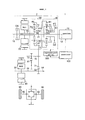
Фиг. 1 представляет собой вид, который показывает общую конфигурацию гибридного транспортного средства, включающего в себя приводную систему согласно варианту осуществления изобретения;FIG. 1 is a view that shows a general configuration of a hybrid vehicle including a drive system according to an embodiment of the invention;
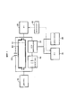
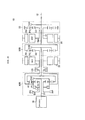
Фиг. 2 представляет собой блок-схему, схематично показывающую контур передачи мощности компонентов транспортного средства с фиг. 1;FIG. 2 is a block diagram schematically showing a power transmission loop of vehicle components of FIG. one;
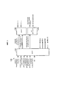
Фиг. 3 представляет собой блок-схему, которая показывает конфигурацию контроллера для транспортного средства на фиг. 1;FIG. 3 is a block diagram that shows the configuration of a controller for the vehicle of FIG. one;
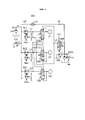
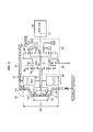
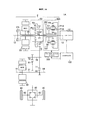
Фиг. 4 представляет собой вид, который схематически показывает конфигурацию гидравлического контура, установленного на гибридном транспортном средстве, показанном на фиг. 1;FIG. 4 is a view that schematically shows the configuration of a hydraulic circuit mounted on the hybrid vehicle shown in FIG. one;
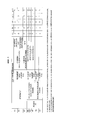
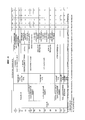
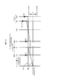
Фиг. 5 представляет собой диаграмму, показывающую каждый режим привода в гибридном транспортном средстве, и управляемые состояния сцепления и тормоза блока передачи в каждом режиме привода;FIG. 5 is a diagram showing each drive mode in a hybrid vehicle and controlled clutch and brake states of a transmission unit in each drive mode;
Фиг. 6 представляет собой номограмму в режиме ЭТ с одним электродвигателем, который является одним из режимов привода, показанных на фиг. 5;FIG. 6 is a nomogram in ET mode with one electric motor, which is one of the drive modes shown in FIG. 5;
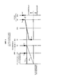
Фиг. 7 представляет собой номограмму в режиме ЭТ с двумя электродвигателями, который является одним из режимов привода, показанных на фиг. 5;FIG. 7 is a nomogram in ET mode with two electric motors, which is one of the drive modes shown in FIG. 5;
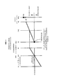
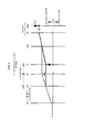
Фиг. 8 представляет собой номограмму в последовательно-параллельном режиме ГТ, который является одним из режимов привода, показанных на фиг. 5;FIG. 8 is a nomogram in series-parallel GT mode, which is one of the drive modes shown in FIG. 5;
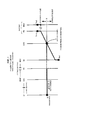
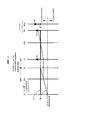
Фиг. 9 представляет собой номограмму в последовательном режиме ГТ, который является одним из режимов привода, показанных на фиг. 5;FIG. 9 is a sequential GT mode nomogram, which is one of the drive modes shown in FIG. 5;
Фиг. 10 представляет собой вид, который показывает конструкцию корпуса приводной системы, показанной на фиг. 1;FIG. 10 is a view that shows the housing structure of the drive system shown in FIG. one;
Фиг. 11 представляет собой диаграмму, которая показывает управляемые состояния сцепления и тормоза блока передачи в каждом режиме привода в соответствии с альтернативным вариантом осуществления настоящего изобретения;FIG. 11 is a diagram that shows the controlled clutch and brake states of a transmission unit in each drive mode in accordance with an alternative embodiment of the present invention;
Фиг. 12 представляет собой номограмму для иллюстрации операций линии Е4 и линии Е5 среди режимов привода в соответствии с альтернативным вариантом осуществления, показанным на фиг. 11;FIG. 12 is a nomogram for illustrating operations of line E4 and line E5 among drive modes in accordance with an alternative embodiment shown in FIG. eleven;
Фиг. 13 представляет собой номограмму для иллюстрации операций линий Н6-Н8 среди режимов привода в соответствии с альтернативным вариантом осуществления, показанным на фиг. 11;FIG. 13 is a nomogram for illustrating the operations of lines H6-H8 among drive modes in accordance with an alternative embodiment shown in FIG. eleven;
Фиг. 14 представляет собой вид, который показывает первый альтернативный вариант осуществления зубчатого механизма гибридного транспортного средства, показанного на фиг. 1; иFIG. 14 is a view that shows a first alternative embodiment of the gear mechanism of the hybrid vehicle shown in FIG. one; and
Фиг. 15 представляет собой вид, который показывает второй альтернативный вариант осуществления зубчатого механизма гибридного транспортного средства, показанного на фиг. 1.FIG. 15 is a view that shows a second alternative embodiment of the gear mechanism of the hybrid vehicle shown in FIG. one.
ПОДРОБНОЕ ОПИСАНИЕ ВАРИАНТОВ ОСУЩЕСТВЛЕНИЯDETAILED DESCRIPTION OF EMBODIMENTS
[0022] Далее будет описан вариант осуществления изобретения со ссылкой на прилагаемые чертежи. Аналогичные ссылочные позиции обозначают одни и те же или соответствующие части в последующем варианте осуществления, и их описание не будет повторяться.[0022] An embodiment of the invention will now be described with reference to the accompanying drawings. Similar reference numerals indicate the same or corresponding parts in a subsequent embodiment, and their description will not be repeated.
[0023] Фиг. 1 представляет собой вид, который показывает общую конфигурацию гибридного транспортного средства, включающего в себя приводную систему в соответствии с вариантом осуществления изобретения.[0023] FIG. 1 is a view that shows a general configuration of a hybrid vehicle including a drive system in accordance with an embodiment of the invention.
[0024] Как показано на фиг. 1, гибридное транспортное средство 1 включает в себя двигатель 10, приводную систему 2, ведущие колеса 90 и контроллер 100. Приводная система 2 включает в себя первый электродвигатель-генератор (далее именуемый первым ЭГ) 20, который является первой вращающейся электрической машиной, второй электродвигатель-генератор (далее именуемый вторым ЭГ) 30, который представляет собой вторую вращающуюся электрическую машину, блок 40 передачи, блок 50 дифференциала, сцепление CS, входной вал 21, передаточный вал 70, который является выходным валом приводной системы 2, дифференциальную зубчатую передачу 80 и гидравлический контур 500.[0024] As shown in FIG. 1, the
[0025] Гибридное транспортное средство 1 представляет собой переднеприводное гибридное транспортное средство с передним расположением двигателя (ПП), которое движется с использованием мощности, по меньшей мере, либо двигателя 10, либо первого ЭГ 20 и второго ЭГ 30. Гибридное транспортное средство 1 может представлять собой гибридное транспортное средство с разъемным подключением, аккумуляторная батарея (не показана) которого может перезаряжаться от внешнего источника питания.[0025] The
[0026] Двигатель 10 представляет собой, например, двигатель внутреннего сгорания, такой как бензиновый двигатель и дизельный двигатель. Каждый из первого ЭГ 20 и второго ЭГ 30 представляет собой, например, синхронный двигатель с постоянными магнитами, который включает в себя ротор, в который встроены постоянные магниты. Приводная система 2 представляет собой приводную систему с двумя осями, в которой первый ЭГ 20 расположен вдоль первой оси 12, соосно коленчатому валу двигателя 10, а второй ЭГ 30 расположен вдоль второй оси 14, отличной от первой оси 12. Первая ось 12 и вторая ось 14 параллельны друг другу.[0026] The
[0027] Вдоль первой оси 12 дополнительно расположены блок 40 передачи, блок 50 дифференциала и сцепление CS. Блок 40 передачи, блок 50 дифференциала, первый ЭГ 20 и сцепление CS расположены в указанном порядке со стороны, близкой к двигателю 10.[0027] Along the
[0028] Первый ЭГ 20 выполнен так, чтобы иметь возможность принимать мощность от двигателя 10. Более конкретно, входной вал 21 приводной системы 2 соединен с коленчатым валом двигателя 10. Входной вал 21 проходит вдоль первой оси 12 в направлении от двигателя 10. Входной вал 21 соединен со сцеплением CS на ее дальнем конце, проходящем от двигателя 10. Вращающийся вал 22 первого ЭГ 20 пролегает в цилиндрической форме вдоль первой оси 12. Входной вал 21 проходит через внутреннюю часть вращающегося вала 22 на участке до того, как входной вал 21 соединяется со сцеплением CS. Входной вал 21 соединен с вращающимся валом 22 первого ЭГ 20 через сцепление CS.[0028] The
[0029] Сцепление CS расположено в контуре передачи мощности от двигателя 10 к первому ЭГ 20. Сцепление CS представляет собой гидравлический элемент с фрикционным зацеплением, который способен соединять входной вал 21 с вращающимся валом 22 первого ЭГ 20. Когда сцепление CS переводится в включенное состояние, входной вал 21 и вращающийся вал 22 соединяются друг с другом, и обеспечивается передача мощности от двигателя 10 к первому ЭГ 20. Когда сцепление CS переводится в выключенное состояние, соединение входного вала 21 с вращающимся валом 22 расцепляется, и передача мощности от двигателя 10 к первому ЭГ 20 через сцепление CS прерывается.[0029] The CS clutch is located in the power transfer circuit from the
[0030] Блок 40 передачи переключает мощность от двигателя 10, а затем выводит мощность на блок 50 дифференциала. Блок 40 передачи включает в себя планетарный механизм с одной ведущей шестерней, сцепление С1 и тормоз В1. Планетарный зубчатый механизм с одинарными ведущими шестернями включает в себя солнечную шестерню S1, ведущие шестерни Р1, кольцевую шестерню R1 и водило СА1.[0030] The
[0031] Солнечная шестерня S1 выполнена так, что центр вращения солнечной шестерни S1 совпадает с первой осью 12. Кольцевая шестерня R1 расположена соосно с солнечной шестерней S1 на радиально внешней стороне солнечной шестерни S1. Ведущие шестерни Р1 расположены между солнечной шестерней S1 и кольцевой шестерней R1, и находятся в зацеплении с солнечной шестерней S1 и кольцевой шестерней R1. Ведущие шестерни Р1 вращательно поддерживаются водилом СА1. Водило СА1 соединено с входным валом 21 и вращается за одно целое с входным валом 21. Каждая из ведущих шестерней Р1 выполнена так, чтобы вращаться вокруг первой оси 12 и вращаться вокруг центральной оси ведущих шестерен Р1.[0031] The sun gear S1 is configured so that the center of rotation of the sun gear S1 coincides with the
[0032] Как показано на фиг. 6 - фиг. 9, фиг. 12 и фиг. 13 (описанных ниже), скорость вращения солнечной шестерни S1, скорость вращения водила СА1 (т.е. скорость вращения двигателя 10) и скорость вращения кольцевой шестерни R1 находятся в отношении, обозначенном точками, которые связаны прямой линией на каждой из номограмм (т.е. отношении, которое, когда определяются любые две скорости вращения, определяет также оставшуюся скорость вращения).[0032] As shown in FIG. 6 - FIG. 9, FIG. 12 and FIG. 13 (described below), the rotation speed of the sun gear S1, the rotation speed of the carrier CA1 (i.e., the rotation speed of the engine 10) and the rotation speed of the ring gear R1 are in the ratio indicated by the points that are connected by a straight line on each of the nomograms (i.e. i.e., the ratio which, when any two rotational speeds are determined, also determines the remaining rotational speed).
[0033] В настоящем варианте осуществления изобретения водило СА1 выполнено в качестве входного элемента, на который подается мощность от двигателя 10, а кольцевая шестерня R1 выполнена в качестве выходного элемента, который выводит мощность, подаваемую на водило СА1. Благодаря использованию планетарного зубчатого механизма, включающего в себя солнечную шестерню S1, ведущие шестерни Р1, кольцевую шестерню R1 и водило СА1, мощность, подаваемая на водило СА1, переключается и выдается с кольцевой шестерни R1.[0033] In the present embodiment, the carrier CA1 is configured as an input member to which power is supplied from the
[0034] Сцепление С1 представляет собой гидравлический элемент с фрикционным зацеплением, который способен соединять солнечную шестерню S1 с водилом СА1. Когда сцепление С1 находится во включенном состоянии, солнечная шестерня S1 водило СА1 соединены друг с другом и вращаются за одно целое друг с другом. Когда сцепление С1 переводится в выключенное состояние, совместное вращение солнечной шестерни S1 и водила СА1 отменяется.[0034] Clutch C1 is a hydraulic element with friction mesh that is capable of connecting the sun gear S1 to the carrier CA1. When the clutch C1 is in the on state, the sun gear S1 of the carrier CA1 are connected to each other and rotate integrally with each other. When the clutch C1 is turned off, the joint rotation of the sun gear S1 and the carrier CA1 is canceled.
[0035] Тормоз В1 представляет собой гидравлический элемент с фрикционным зацеплением, который способен ограничивать (блокировать) вращение солнечной шестерни S1. Когда тормоз В1 находится во включенном состоянии, солнечная шестерня S1 фиксируется к телу корпуса приводной системы, а вращение солнечной шестерни S1 ограничивается. Когда тормоз В1 находится в выключенном состоянии (расцепленном состоянии), солнечная шестерня S1 отделена от тела корпуса приводной системы, и вращение солнечной шестерни S1 разрешено.[0035] The brake B1 is a friction engagement hydraulic member that is capable of restricting (blocking) the rotation of the sun gear S1. When the brake B1 is in the ON state, the sun gear S1 is fixed to the body of the housing of the drive system, and the rotation of the sun gear S1 is limited. When the brake B1 is in the off state (disengaged state), the sun gear S1 is separated from the body of the housing of the drive system, and the rotation of the sun gear S1 is allowed.
[0036] Передаточное отношение (отношение скорости вращения водила СА1, которое является входным элементом, к скорости вращения кольцевой шестерни R1, которая является выходным элементом, в частности, скорости вращения водила СА1 /скорости вращения кольцевой шестерни R1) блока 40 передачи изменяется в ответ на комбинацию состояний включения/выключения сцепления С1 и тормоза В1. Когда сцепление С1 включено и тормоз В1 выключен, устанавливается положение Lo низкой передачи, в котором установлено передаточное отношение 1,0 (состояние с прямым соединением). Когда сцепление С1 выключено, и включен тормоз В1, устанавливается положение Hi высокой передачи, при котором передаточное отношение меньше чем 1,0 (например, 0,7 и так называемое состояние повышающей передачи). Когда сцепление С1 включено и тормоз В1 включен, вращение солнечной шестерни S1 и вращение водила СА1 ограничены, поэтому вращение кольцевой шестерни R1 также ограничено.[0036] The gear ratio (the ratio of the rotation speed of the carrier CA1, which is the input element, to the rotation speed of the ring gear R1, which is the output element, in particular, the rotation speed of the carrier CA1 / rotation speed of the ring gear R1) of the
[0037] Блок 40 передачи выполнен с возможностью переключения между не нейтральным состоянием и нейтральным состоянием. В не нейтральном состоянии передается мощность. В нейтральном состоянии мощность не передается. В настоящем варианте осуществления изобретения вышеописанное состояние с прямым подключением и состояние повышающей передачи соответствуют не нейтральному состоянию. С другой стороны, когда и сцепление С1, и тормоз В1 выключены, что позволяет водилу СА1 двигаться до полной остановки на первой оси 12. Таким образом, достигается нейтральное состояние, в котором мощность, передаваемая от двигателя 10 на водило СА1, не передается от водила СА1 на кольцевую шестерню R1.[0037] The
[0038] Блок 50 дифференциала включает в себя планетарный зубчатый механизм с одинарными ведущими шестернями и ведущую шестерню 51 контрпривода. Планетарный зубчатый механизм с одинарными ведущими шестернями шестерней включает в себя солнечную шестерню S2, ведущие шестерни Р2, кольцевую шестерню R2 и водило СА2.[0038] The
[0039] Солнечная шестерня S2 выполнена так, что центр вращения солнечной шестерни S2 совпадает с первой осью 12. Кольцевая шестерня R2 расположена соосно с солнечной шестерней S2 на радиально внешней стороне солнечной шестерни S2. Ведущие шестерни Р2 расположены между солнечной шестерней S2 и кольцевой шестерней R2 и находятся в зацеплении с солнечной шестерней S2 и кольцевой шестерней R2. Ведущие шестерни Р2 поддерживаются с возможностью вращения водилом СА2. Водило СА2 соединено с кольцевой шестерней R1 блока 40 передачи и вращается за одно целое с кольцевой шестерней R1. Каждая из ведущих шестерней Р2 выполнена так, чтобы вращаться вокруг первой оси 12 и вращаться вокруг центральной оси ведущих шестерен Р2.[0039] The sun gear S2 is configured such that the center of rotation of the sun gear S2 coincides with the
[0040] Вращающийся вал 22 первого ЭГ 20 соединен с солнечной шестерней S2. Вращающийся вал 22 первого ЭГ 20 вращается за одно целое с солнечной шестерней S2. Ведущая шестерня 51 контрпривода соединена с кольцевой шестерней R2. Ведущая шестерня 51 контрпривода представляет собой выходную шестерню блока 50 дифференциала. Выходная шестерня вращается за одно целое с кольцевой шестерней R2.[0040] The rotating
[0041]Как показано на фиг. 6 - фиг. 9, фиг. 12 и фиг. 13, скорость вращения солнечной шестерни S2 (то есть скорость вращения первого ЭГ 20), скорость вращения водила СА2 и скорость вращения кольцевой шестерни R2 находятся в отношении, обозначенном точками, которые соединены по прямой на каждой из номограмм (т.е. отношении, при котором, когда определяются любые две скорости вращения, также определяется оставшаяся скорость вращения). Поэтому, когда скорость вращения водила СА2 является заданным значением, возможно плавно изменять скорость вращения кольцевой шестерни R2, регулируя скорость вращения первого ЭГ 20.[0041] As shown in FIG. 6 - FIG. 9, FIG. 12 and FIG. 13, the rotation speed of the sun gear S2 (i.e., the rotation speed of the first EG 20), the rotation speed of the carrier CA2 and the rotation speed of the ring gear R2 are in the relation indicated by the points that are connected in a straight line on each of the nomograms (i.e., the ratio, which, when any two rotation speeds are determined, the remaining rotation speed is also determined). Therefore, when the rotation speed of the carrier CA2 is a predetermined value, it is possible to smoothly change the rotation speed of the ring gear R2 by adjusting the rotation speed of the
[0042] Передаточный вал 70 проходит параллельно первой оси 12 и второй оси 14. Передаточный вал 70 расположен параллельно вращающемуся валу 22 первого ЭГ 20 и вращающемуся валу 31 второго ЭГ 30. Ведомая шестерня 71 и приводная шестерня 72 расположена на встречном валу 70. Ведомая шестерня 71 находится в зацеплении с ведущей шестерней 51 контрпривода блока 50 дифференциала. То есть мощность двигателя 10 и мощность первого ЭГ 20 передаются на передаточный вал 70 через ведущую шестерню 51 контрпривода блока 50 дифференциала.[0042] The
[0043] Блок 40 передачи и блок 50 дифференциала соединены последовательно друг с другом в контуре передачи мощности от двигателя 10 на передаточный вал 70. Соответственно, мощность от двигателя 10 переключается в блоке 40 передачи и в блоке 50 дифференциала и затем передается на передаточный вал 70.[0043] The
[0044] Ведомая шестерня 71 находится в зацеплении с редуктором 32, соединенным с вращающимся валом 31 второго ЭГ 30. То есть мощность второго ЭГ 30 передается на передаточный вал 70 через редуктор 32.[0044] The driven
[0045] Приводная шестерня 72 находится в зацеплении с коронной шестерней 81 дифференциальной зубчатой передачи 80. Дифференциальная зубчатая передача 80 соединена с правым и левым ведущими колесами 90 через соответствующие правые и левые ведущие валы 82. То есть вращение передаточного вала 70 передается на правый и левый ведущие валы 82 через дифференциальную зубчатую передачу 80.[0045] The
[0046] С вышеописанной конфигурацией, в которой расположено сцепление CS, гибридное транспортное средство 1 может работать в режиме, в котором используется последовательно-параллельная система (далее именуемая последовательно-параллельным режимом), а также может работать в режиме, в котором используется последовательная система (далее именуемая последовательным режимом). То, как мощность передается от двигателя в каждом режиме, будет описано со ссылкой на схематический вид, показанный на фиг. 2.[0046] With the above configuration in which the CS clutch is located,
[0047] Фиг. 2 представляет собой блок-схему, схематично показывающую контур передачи мощности компонентов транспортного средства с фиг. 1. Как показано на фиг. 2, гибридное транспортное средство 1 включает в себя двигатель 10, первый ЭГ 20, второй ЭГ 30, блок 40 передачи, блок 50 дифференциала, аккумулятор 60 и сцепление CS.[0047] FIG. 2 is a block diagram schematically showing a power transmission loop of vehicle components of FIG. 1. As shown in FIG. 2, the
[0048] Второй ЭГ 30 выполнен таким образом, чтобы обеспечить выходную мощность на ведущие колеса 90. Блок 40 передачи включает в себя входной элемент и выходной элемент. Мощность двигателя 10 подается на входной элемент. Выходной элемент выводит входную мощность, подаваемую на входной элемент. Блок 40 передачи выполнен с возможностью переключения между не нейтральным состоянием и нейтральным состоянием. В не нейтральном состоянии мощность передается между входным элементом и выходным элементом. В нейтральном состоянии мощность между входным элементом и выходным элементом не передается.[0048] The
[0049] Аккумулятор 60 подает электроэнергию на первый ЭГ 20 или второй ЭГ 30 во время обеспечения запитывания соответствующего либо первого ЭГ 20, либо второго ЭГ 30 и накапливает электроэнергию, генерируемую первым ЭГ 20 или вторым ЭГ 30 во время регенерации соответствующего либо первого ЭГ 20, либо второго ЭГ 30.[0049] The
[0050] Блок 50 дифференциала включает в себя первый вращающийся элемент, второй вращающийся элемент и третий вращающийся элемент. Первый вращающийся элемент соединен с первым ЭГ 20. Второй вращающийся элемент соединен со вторым ЭГ 30 и ведущими колесами 90. Третий вращающийся элемент соединен с выходным элементом блока 40 передачи. Блок 50 дифференциала выполнен так, что, например, в случае, например, механизма планетарной шестерни или т.п., когда определяются скорости вращения любых двух из вращающихся элементов с первого по третий, определяется скорость вращения оставшегося одного из вращающегося элементов с первого по третий.[0050] The
[0051] Гибридное транспортное средство 1 сконфигурировано так, чтобы иметь возможность передавать мощность от двигателя 10 к первому ЭГ 20 с использованием, по меньшей мере, одного из двух контуров K1, К2, через которые передается мощность. Контур К1 представляет собой контур, через который мощность передается от двигателя 10 к первому ЭГ 20 через блок 40 передачи и блок 50 дифференциала. Контур К2 отличается от контура К1 и является контуром, через который передается мощность от двигателя 10 к первому ЭГ 20. Сцепление CS расположено на контуре К2 и может переключаться между включенным состоянием и выключенным состоянием. Во включенном состоянии мощность передается от двигателя 10 к первому ЭГ 20. В выключенном состоянии передача мощности от двигателя 10 к первому ЭГ 20 прерывается.[0051] The
[0052] В режиме ГТ, в котором работает двигатель, либо сцепление С1, либо тормоз В1 переводится во включенное состояние, а другой элемент - либо сцепление С1, либо тормоз В1 переводится в выключенное состояние. Таким образом, когда блок 40 передачи переводится в не нейтральное состояние, мощность передается от двигателя 10 к первому ЭГ 20 по контуру К1. В это время, когда сцепление CS переводится в выключенное состояние для одновременного прерывания контура К2, транспортное средство работает в последовательно-параллельном режиме.[0052] In the GT mode, in which the engine is running, either the clutch C1 or the brake B1 is turned on, and the other element is either the clutch C1 or the brake B1 is turned off. Thus, when the
[0053] С другой стороны, в режиме ГТ, в котором работает двигатель, когда мощность передается по контуру К2 путем непосредственного соединения двигателя 10 с первым ЭГ 20 с помощью сцепления CS, и контур К1 прерывается посредством управления блоком 40 передачи, так что блок 40 передачи переводится в нейтральное состояние, путем перевода как сцепления С1, так и тормоза В1 в выключенное состояние, транспортное средство работает в последовательном режиме. В это время в блоке 50 дифференциала, вращающийся элемент, соединенный с блоком 40 передачи, свободно вращается, поэтому другие два вращающихся элемента не влияют друг на друга и могут вращаться. Соответственно, возможно независимо выполнять операцию генерирования электрической энергии путем вращения первого ЭГ 20 с использованием вращения двигателя 10 и работы вращения ведущих колес путем управления вторым ЭГ 30 с использованием генерируемой электрической энергии или электрической энергии, накопленной в аккумуляторе 60.[0053] On the other hand, in the GT mode in which the engine is running, when power is transmitted along the circuit K2 by directly connecting the
[0054] Блоку 40 передачи не всегда требуется иметь возможность изменять передаточное отношение. Пока возможно прерывать передачу мощности между двигателем 10 и блоком 50 дифференциала в контуре К1, применяется только сцепление.[0054] The
[0055] Фиг. 3 представляет собой блок-схему, показывающую конфигурацию контроллера 100 транспортного средства, проиллюстрированную на фиг. 1. Как показано на фиг. 3, контроллер 100 включает в себя ЭБУ 150 ГТ, ЭБУ 160 ЭГ и ЭБУ 170 двигателя. Каждый из ЭБУ 150 ГТ, ЭБУ 160 ЭГ и ЭБУ 170 двигателя является электронным блоком управления, включающим в себя компьютер. Количество ЭБУ не ограничено тремя. Суммарный единый ЭБУ может быть выполнен как единое целое, либо может быть предусмотрено два или четыре, или более разделенных ЭБУ.[0055] FIG. 3 is a block diagram showing a configuration of a
[0056] ЭБУ 160 ЭГ управляет первым ЭГ 20 и вторым ЭГ 30. Например, ЭБУ 160 ЭГ управляет выходным крутящим моментом первого ЭГ 20, регулируя значение тока, которое подается на первый ЭГ 20, и управляет выходным крутящим моментом второго ЭГ 30 путем регулирования значения тока, подаваемого на второй ЭГ 30.[0056]
[0057] ЭБУ 170 двигателя управляет двигателем 10. ЭБУ 170 двигателя, например, управляет степенью открывания электронного дроссельного клапана двигателя 10, управляет зажиганием двигателя, выдавая сигнал зажигания, или управляет впрыском топлива в двигатель 10. ЭБУ 170 двигателя управляет выходным крутящим моментом двигателя 10 посредством управления степенью открывания через электронный дроссельный клапан, управление впрыском, управление зажиганием и т.п.[0057] The
[0058] ЭБУ 150 ГТ полностью управляет всем транспортным средством. Датчик скорости транспортного средства, датчик количества операций ускорителя, датчик скорости вращения ЭГ1, датчик скорости вращения ЭГ2, датчик скорости вращения выходного вала, датчик аккумулятора и т.п., подключены к ЭБУ 150 высокого напряжения. С помощью этих датчиков, ЭБУ 150 ГТ получает скорость транспортного средства, количество операций ускорителя, скорость вращения первого ЭГ 20, скорость вращения второго ЭГ 30, скорость вращения выходного вала системы передачи мощности, состояние заряда СЗ аккумулятора, и т.п.[0058] The 150 GT ECU fully controls the entire vehicle. The vehicle speed sensor, accelerator operation number sensor, EG1 rotation speed sensor, EG2 rotation speed sensor, output shaft rotation speed sensor, battery sensor and the like are connected to
[0059] ЭБУ 150 ГТ рассчитывает требуемое приводное усилие, требуемую мощность, требуемый крутящий момент и т.п., для транспортного средства на основе полученной информации. ЭБУ 150 ГТ определяет выходной крутящий момент первого ЭГ 20 (далее также именуемый крутящим моментом ЭГ1), выходной крутящий момент второго ЭГ 30 (далее также именуемый крутящим моментом ЭГ2) и выходной крутящий момент двигателя 10 (далее также именуемый крутящим моментом двигателя) на основе рассчитанных требуемых значений. ЭБУ 150 ГТ выдает командное значение крутящего момента ЭГ1 и командное значение крутящего момента ЭГ2 для ЭБУ 160 ЭГ. ЭБУ 150 ГТ выводит командное значение крутящего момента двигателя на ЭБУ 170 двигателя.[0059] The 150 GT ECU calculates the required drive force, the required power, the required torque, and the like, for the vehicle based on the information received.
[0060] ЭБУ 150 ГТ управляет сцеплениями C1, CS и тормозом В1 на основе режима привода (описано ниже) и тому подобного. ЭБУ 150 ГТ выдает на гидравлический контур 500, показанный на фиг. 1, командное значение (PbC1) гидравлического давления, которое прикладывается к сцеплению С1, командное значение (PbCS) гидравлического давления, которое прикладывается к сцеплению CS сцепления, и командное значение (PbB1) гидравлического давления, которое прикладывается к тормозу В1. ЭБУ 150 ГТ выдает управляющий сигнал NM и управляющий сигнал S/C в гидравлический контур 500, показанный на фиг. 1.[0060] The 150 GT ECU controls the clutches C1, CS and brake B1 based on the drive mode (described below) and the like. An
[0061] Гидравлический контур 500, показанный на фиг. 1, управляет величинами гидравлического давления, которые соответственно подаются на сцепление С1, а тормоз В1 в ответ на командные значения PbC1, PbB1 управляет электрическим масляным насосом в ответ на управляющий сигнал NM, и управляет тем, разрешать или запрещать одновременное включение сцепления С1, тормоза В1 и сцепления CS в ответ на управляющий сигнал S/C.[0061] The
[0062] Далее будет описана конфигурация гидравлического контура. На фиг. 4 проиллюстрирован вид, который схематически показывает конфигурацию гидравлического контура 500, установленного на гибридном транспортном средстве 1. Гидравлический контур 500 включает в себя механический масляный насос (далее также именуемый ММН) 501, электрический масляный насос (далее именуемый также ЭМН) 502, клапаны 510, 520 регулирования давления, линейные соленоидные клапаны SL1, SL2, SL3, клапаны 530, 540, 550 предотвращения одновременной подачи, электромагнитный переключающий клапан 560, обратный клапан 570 и масляные каналы LM, LE, L1, L2, L3, L4.[0062] Next, a hydraulic circuit configuration will be described. In FIG. 4 is a view that schematically shows the configuration of a
[0063] ММН 501 приводится в действие вращением водила СА2 блок 50 дифференциала для создания гидравлического давления. Поэтому, когда водило СА2 вращается, например, при управлении двигателем 10, ММН 501 также приводится в действие; при этом, когда водило СА2 остановлено, ММН 501 также останавливается. ММН 501 выдает сгенерированное гидравлическое давление на масляный канал LM.[0063]
[0064] Гидравлическое давление в масляном контуре LM регулируется (понижается) до заданного давления с помощью клапана 510 регулирования давления. В дальнейшем гидравлическое давление в масляном контуре LM, регулируемое клапаном 510 регулирования давления, именуется линейным давлением PL. Линейное давление PL подается на каждый из линейных электромагнитных клапанов SL1, SL2, SL3.[0064] The hydraulic pressure in the LM oil circuit is regulated (lowered) to a predetermined pressure using the
[0065] Линейный электромагнитный клапан SL1 создает гидравлическое давление для включения сцепления С1 (далее именуемое давлением С1) посредством регулирования линейного давления PL в ответ на значение PbC1 команды гидравлического давления от контроллера 100. Давление С1 подается на сцепление С1 через масляный канал L1.[0065] The linear solenoid valve SL1 generates hydraulic pressure to engage clutch C1 (hereinafter referred to as pressure C1) by adjusting the line pressure PL in response to the hydraulic pressure command value PbC1 from
[0066] Линейный соленоидный клапан SL2 создает гидравлическое давление для включения тормоза В1 (далее именуемое давлением В1), регулируя линейное давление PL в ответ на значение PbB1 команды гидравлического давления от контроллера 100. Давление В1 подается на тормоз В1 через масляный канал L2.[0066] The linear solenoid valve SL2 generates hydraulic pressure to activate the brake B1 (hereinafter referred to as pressure B1) by adjusting the linear pressure PL in response to the hydraulic command pressure PbB1 from the
[0067] Линейный электромагнитный клапан SL3 генерирует гидравлическое давление для включения сцепления CS (далее именуется давлением CS), регулируя линейное давление PL в ответ на значение PbCS команды гидравлического давления от контроллера 100. Давление CS подается на сцепление CS через масляный канал L3.[0067] The linear solenoid valve SL3 generates hydraulic pressure to engage the CS clutch (hereinafter referred to as CS pressure) by adjusting the line pressure PL in response to the PbCS value of the hydraulic pressure command from the
[0068] Клапан 530 предотвращения одновременной подачи расположен в масляном канале L1 и выполнен так, чтобы не допускать одновременного включения сцепления С1 и, по меньшей мере, либо тормоза В1, либо сцепления CS. В частности, масляные каналы L2, L3 соединены с клапаном 530 предотвращения одновременной подачи. Клапан 530 предотвращения одновременной подачи работает с использованием давления В1 и давления CS через масляные каналы L2, L3 в качестве сигнального давления.[0068] The simultaneous
[0069] Когда оба сигнальных давления, которые представляют собой давление В1 и давление CS, не подаются на клапан 530 предотвращения одновременной подачи (то есть, когда и тормоз В1, и сцепление CS выключены), клапан 530 предотвращения одновременной подачи находится в нормальном состоянии, в котором давление С1 подается на сцепление С1. Фиг. 4 иллюстрирует случай, когда клапан 530 предотвращения одновременной подачи находится в нормальном состоянии.[0069] When both signal pressures, which are pressure B1 and pressure CS, are not supplied to the simultaneous feed prevention valve 530 (that is, when both the brake B1 and the CS clutch are turned off), the simultaneous
[0070] С другой стороны, когда, по меньшей мере, одно из сигнальных давлений, которые представляют собой давление В1 и давление CS, подаются на клапан 530 предотвращения одновременной подачи (то есть, когда включен, по меньшей мере, либо тормоз В1, либо сцепление CS), даже когда сцепление С1 включено, клапан 530 предотвращения одновременной подачи переключается в состояние слива, в котором подача давления С1 на сцепление С1 отключается, и гидравлическое давление в сцеплении С1 стравливается наружу. Таким образом, сцепление С1 выключается, поэтому сцепление С1 и, по меньшей мере, либо тормоз В1, либо сцепление CS не может включиться одновременно.[0070] On the other hand, when at least one of the signal pressures, which are pressure B1 and pressure CS, are supplied to the simultaneous feed valve 530 (that is, when at least either brake B1 or clutch CS), even when clutch C1 is engaged, the simultaneous
[0071] Аналогичным образом, клапан 540 предотвращения одновременной подачи работает в ответ на давление С1 и давление CS в качестве сигнального давления, чтобы предотвратить одновременное включение тормоза В1 и, по меньшей мере, либо сцепления С1, либо сцепления CS. В частности, когда оба сигнальных давления, которые представляют собой давление С1 и давление CS, не подаются на клапан 540 предотвращения одновременной подачи, клапан 540 предотвращения одновременной подачи находится в нормальном состоянии, в котором давление В1 подается на тормоз В1. С другой стороны, когда, по меньшей мере, одно из сигнальных давлений, которые представляет собой давление С1 и давление CS, подается на клапан 540 предотвращения одновременной подачи, клапан 540 предотвращения одновременной подачи переключается в состояние слива, в котором подача давления В1 на тормоз В1 отключается, и гидравлическое давление в тормозе В1 стравливается наружу. На фиг. 4 показан случай, когда давление С1 подается на клапан 540 предотвращения одновременной подачи, когда сигнальное давление и клапан 540 предотвращения одновременной подачи находятся в состоянии слива.[0071] Similarly, the simultaneous
[0072] Аналогичным образом, клапан 550 предотвращения одновременной подачи работает с использованием давления С1 и давления В1 в качестве сигнального давления, чтобы предотвратить одновременное включение сцепления CS и, по меньшей мере, либо сцепления С1, либо тормоза В1. В частности, когда оба сигнальных давления, которые представляют собой давление С1 и давление В1, не подаются на клапан 550 предотвращения одновременной подачи, клапан 550 предотвращения одновременной подачи находится в нормальном состоянии, в котором давление CS подается на сцепление CS. С другой стороны, когда, по меньшей мере, одно из сигнальных давлений, которые представляют собой давление С1 и давление В1, подается на клапан 550 предотвращения одновременной подачи, клапан 550 предотвращения одновременной подачи переключается в состояние слива, в котором подача давления CS на сцепление отключается, и гидравлическое давление в сцеплении CS стравливается наружу. Фиг. 4 иллюстрирует случай, когда давление С1 подают на клапан 550 предотвращения одновременной подачи, а клапан 550 предотвращения одновременной подачи находится в состоянии слива.[0072] Similarly, the simultaneous
[0073] ЭМН 502 приводится в действие электродвигателем (далее именуемым также внутренним электродвигателем) 502А, расположенным внутри для генерирования гидравлического давления. Внутренний двигатель 502А управляется управляющим сигналом NM от контроллера 100. Соответственно, ЭМН 502 работает независимо от того, вращается ли водило СА2. ЭМН 502 выдает сгенерированное гидравлическое давление в масляный канал LE.[0073]
[0074] Гидравлическое давление в масляном канале LE регулируется (уменьшается) до заданного давления с помощью клапана 520 регулирования давления. Масляный канал LE соединен с масляным каналом LM через обратный клапан 570. Когда гидравлическое давление в масляном канале LE выше на заданное давление или больше, чем гидравлическое давление в масляном канале LM, открывается обратный клапан 570, и гидравлическое давление в масляном канале LE подается в масляный канал LM через обратный клапан 570. Таким образом, во время остановки ММН 501, также возможно подавать гидравлическое давление на масляный канал LM, путем управления ЭМН 502.[0074] The hydraulic pressure in the oil channel LE is regulated (reduced) to a predetermined pressure using the
[0075] Электромагнитный переключающий клапан 560 переключается во включенное состояние и выключенное состояние в ответ на управляющий сигнал S/C от контроллера 100. Во включенном состоянии электромагнитный переключающий клапан 560 обеспечивает соединение масляного канала LE с масляным каналом L4. В выключенном состоянии электромагнитный переключающий клапан 560 разъединяет масляный канал LE с масляным каналом L4 и стравливает гидравлическое давление в масляном канале L4 наружу. Фиг. 4 иллюстрирует случай, когда электромагнитный переключающий клапан 560 находится в выключенном состоянии.[0075] The
[0076] Масляный канал L4 соединен с клапанами 530, 540 предотвращения одновременной подачи. Когда электромагнитный переключающий клапан 560 находится во включенном состоянии, гидравлическое давление в масляном канале LE подается на клапаны 530, 540 предотвращения одновременной подачи через масляный канал L4 в качестве сигнального давления. Когда сигнальное давление из масляного канала L4 подается на клапан 530 предотвращения одновременной подачи, клапан 530 предотвращения одновременной подачи принудительно фиксируется в нормальном состоянии независимо от того, подается ли сигнальное давление (давление В1) из масляного канала L2. Аналогичным образом, когда сигнальное давление подается из масляного канала L4 на клапан 540 предотвращения одновременной подачи, клапан 540 предотвращения одновременной подачи принудительно закрепляется в нормальном состоянии независимо от того, подается ли сигнальное давление (давление С1) из масляного канала L1. Поэтому, путем управления ЭМН 502 и переключения электромагнитного переключающего клапана 560 во включенное состояние, клапаны 530, 540 предотвращения одновременной подачи одновременно фиксируются в нормальном состоянии. Таким образом, сцепление С1 и тормоз В1 могут включаться одновременно, и включается режим с двумя электродвигателями (описанный ниже).[0076] The oil channel L4 is connected to the
[0077] В дальнейшем подробности режимов управления гибридного транспортного средства 1 будут описаны со ссылкой на диаграмму взаимодействия операций и номограммы.[0077] Hereinafter, details of the control modes of the
[0078] Фиг. 5 представляет собой диаграмму, показывающую каждый режим привода и управляемые состояния сцепления С1 и тормоза В1 блока 40 передачи в каждом режиме привода.[0078] FIG. 5 is a diagram showing each drive mode and controlled states of the clutch C1 and brake B1 of the
[0079] Контроллер 100 заставляет гибридное транспортное средство 1 двигаться в режиме электродвигателя (далее именуемого режимом ЭТ) или гибридном режиме (далее именуемого режимом ГТ). Режим ЭТ является режимом управления, в котором двигатель 10 остановлен, и гибридное транспортное средство 1 вынуждено двигаться с использованием мощности, по меньшей мере, либо первого ЭГ 20, либо второго ЭГ 30. Режим ГТ является режимом управления, в котором гибридное транспортное средство 1 вынуждено двигаться с использованием мощности двигателя 10 и мощности второго ЭГ 30. Каждый из режимов ЭТ и ГТ дополнительно подразделяется на некоторые режимы управления.[0079] The
[0080] На фиг. 5, C1, B1, CS, ЭГ1 и ЭГ2 обозначают, соответственно, сцепление С1, тормоз В1, сцепление CS, первый ЭГ 20 и второй ЭГ 30. Знак окружности (О) в каждом из столбцов C1, B1, CS указывает на состояние сцепления, крестообразный знак (×) указывает на выключенное состояние, а треугольный знак (Δ) указывает на включение сцепления С1 и тормоза В1 во время торможения двигателем. Знак Г в каждом столбце ЭГ1 и столбце ЭГ2 указывает, что ЭГ1 или ЭГ2 в основном работают как генератор. Знак Э в каждом из столбцов ЭГ1 и столбцов ЭГ2 указывает, что ЭГ1 или ЭГ2 в основном работают как двигатель.[0080] FIG. 5, C1, B1, CS, EG1 and EG2 respectively designate clutch C1, brake B1, clutch CS,
[0081] В режиме ЭТ контроллер 100 избирательно переключается между режимом с одним электродвигателем и режимом с двумя электродвигателями в ответ на требуемый пользователем крутящий момент и т.п. В режиме с одним электродвигателем гибридное транспортное средство 1 движется с использованием мощности второго ЭГ 30. В режиме с двумя электродвигателями гибридное транспортное средство 1 движется с использованием мощности как первого ЭГ 20, так и второго ЭГ 30.[0081] In ET mode, the
[0082] Когда нагрузка приводной системы 2 низкая, используется режим с одним электродвигателем. Когда нагрузка системы 2 привода становится высокой, режим привода изменяется на режим с двумя электродвигателями.[0082] When the load of the
[0083] Как показано в линии Е1 на фиг. 5, когда гибридное транспортное средство 1 приводится в движение (движется вперед или назад) в режиме ЭТ с одним электродвигателем, контроллер 100 переводит блок 40 передачи в нейтральное состояние (состояние, в котором передача мощности отсутствует), выключая сцепление С1 и выключая тормоз В1. В это время контроллер 100 заставляет первый ЭГ 20 работать в основном как фиксирующее средство для фиксации скорости вращения солнечной шестерни S2 до нуля и заставляет второй ЭГ 30 работать в основном как двигатель (см. фиг. 6 (описано ниже)). Чтобы обеспечить работу первого ЭГ 20 как средства фиксации, возможно управлять током первого ЭГ 20, за счет возвратно-вращательного движения скорости вращения первого ЭГ 20 таким образом, чтобы скорость вращения становилась равной нулю. Когда скорость вращения первого ЭГ 20 остается равной нулю, даже когда крутящий момент равен нулю, крутящий момент может быть использован без добавления тока. Когда блок 40 передачи переведен в нейтральное состояние, двигатель 10 не вращается во время торможения, поэтому потери меньше на эту величину, и возможно восстановить большую регенерированную электроэнергию.[0083] As shown in line E1 in FIG. 5, when the
[0084] Как показано в линии Е2 на фиг. 5, когда гибридное транспортное средство 1 тормозится в режиме ЭТ с одним электродвигателем и требуется торможение двигателем, контроллер 100 включает любой из сцепления С1 и тормоза В1. Например, когда тормозного усилия недостаточно только с рекуперативным тормозом, вместе с регенеративным тормозом используется торможение двигателем. Например, когда СЗ аккумулятора находится близко к состоянию полной зарядки, регенерированная электрическая энергия не может быть в состоянии зарядки, поэтому возможно установить состояние торможения двигателем.[0084] As shown in line E2 in FIG. 5, when the
[0085] Путем включения любого из, либо сцепления С1, либо тормоза В1, устанавливается так называемое состояние торможения двигателем. В состоянии торможения двигателем вращение ведущих колес 90 передается на двигатель 10, и двигатель 10 вращается. В это время контроллер 100 заставляет первый ЭГ 20 работать в основном как двигатель и заставляет второй ЭГ 30 работать в основном как генератор.[0085] By engaging any of either the clutch C1 or the brake B1, a so-called engine braking condition is established. In a state of engine braking, the rotation of the
[0086] С другой стороны, как показано на линии Е3 на фиг. 5, когда гибридное транспортное средство 1 приводится в движение (движется вперед или назад) в режиме ЭТ с двумя электродвигателями, контроллер 100 ограничивает (блокирует) вращение кольцевой шестерни R1 блока 40 передачи путем включения сцепления С1 и включения тормоза В1. Таким образом, вращение водила СА2 блока 50 дифференциала, связанного с кольцевой шестерней R1 блока 40 передачи, также ограничено (заблокировано), поэтому водило СА2 блока 50 дифференциала удерживается в остановленном состоянии (скорость вращения двигателя Ne=0). Контроллер 100 заставляет первый ЭГ 20 и второй ЭГ 30 работать в основном как электродвигатели (см. фиг. 7 (описано ниже)).[0086] On the other hand, as shown on line E3 in FIG. 5, when the
[0087] В режиме ЭТ (режиме с одним электродвигателем или режиме с двумя электродвигателями) двигатель 10 останавливается, поэтому ММН 501 также останавливается. Поэтому в режиме ЭТ сцепление С1 или тормоз В1 включается с помощью гидравлического давления, создаваемого ЭМН 502.[0087] In ET mode (single-motor mode or dual-motor mode), the
[0088] В режиме ГТ контроллер 100 заставляет первый ЭГ 20 работать в основном как генератор и заставляет второй ЭГ 30 работать в основном как двигатель.[0088] In GT mode, the
[0089] В режиме ГТ контроллер 100 устанавливает режим управления либо в последовательно-параллельный режим, либо в последовательный режим.[0089] In the GT mode, the
[0090] В последовательно-параллельном режиме часть мощности двигателя 10 используется для привода ведущих колес 90, а оставшаяся часть мощности двигателя 10 используется в качестве мощности для выработки электроэнергии в первом ЭГ 20. Второй ЭГ 30 управляет ведущими колесами 90 с использованием электрической энергии, генерируемой первым ЭГ 20. В последовательно-параллельном режиме контроллер 100 изменяет соотношение скоростей блока 40 передачи в ответ на скорость транспортного средства.[0090] In serial-parallel mode, part of the power of the
[0091] Когда гибридное транспортное средство 1 движется вперед в промежуточном или низкоскоростном диапазоне, контроллер 100 устанавливает положение Lo низкой передачи (см. сплошную линию на фиг. 8 (описано ниже)), включая сцепление С1 и выключая тормоз В1, как показано в строке Н2 на фиг. 5. С другой стороны, когда гибридное транспортное средство 1 двигается вперед в высокоскоростном диапазоне, контроллер 100 устанавливает положение Hi высокой передачи (см. пунктирную линию на фиг. 8 (описано ниже)), выключая сцепление С1 и включая тормоз В1, как показано в строке H1 на фиг. 5. Либо, когда установлено положение высокой передачи, или, когда установлено положение низкой передачи, блок 40 передачи и блок 50 дифференциала работают в целом как бесступенчатая трансмиссия.[0091] When the
[0092] Когда гибридное транспортное средство 1 движется задним ходом, контроллер 100 включает сцепление С1 и выключает тормоз В1, как показано в строке Н3 на фиг. 5. Когда в СЗ аккумулятора есть запас заряда, контроллер 100 вращает второй ЭГ 30 только в обратном направлении; Тогда как, когда в СЗ аккумулятора нет запаса заряда, контроллер 100 генерирует электроэнергию с использованием первого ЭГ 20, управляя двигателем 10 и вращая второй ЭГ 30 в обратном направлении.[0092] When the
[0093] В последовательном режиме вся мощность двигателя 10 используется как мощность для генерирования электроэнергии с использованием первого ЭГ 20. Второй ЭГ 30 управляет ведущими колесами 90 с использованием электрической мощности, генерируемой первым ЭГ 20. В последовательном режиме, когда гибридное транспортное средство 1 движется вперед или, когда гибридное транспортное средство 1 движется задним ходом, контроллер 100 выключает сцепление С1 и тормоз В1 и включает сцепление CS (см. фиг. 9 (описано ниже)), как показано в Н4 и в строке Н5 на фиг. 5.[0093] In sequential mode, the entire power of
[0094] В режиме ГТ двигатель 10 работает, при этом ММН 501 также работает. Поэтому в режиме ГТ сцепление С1, сцепление CS или тормоз В1 в основном задействованы с использованием гидравлического давления, создаваемого ММН 501.[0094] In the GT mode, the
[0095] В дальнейшем состояния вращающихся элементов в каждом рабочем режиме, показанные на фиг. 5, будут описаны со ссылкой на номограммы.[0095] Hereinafter, the states of the rotating elements in each operating mode shown in FIG. 5 will be described with reference to nomograms.
[0096] Фиг. 6 представляет собой номограмму в режиме с одним электродвигателем. Фиг. 7 представляет собой номограмму в режиме ЭТ с двумя электродвигателями. Фиг. 8 - представляет собой номограмму в последовательно-параллельном режиме. Фиг. 9 представляет собой номограмму в последовательном режиме.[0096] FIG. 6 is a nomogram in single-motor mode. FIG. 7 is a nomogram in ET mode with two electric motors. FIG. 8 - is a nomogram in serial-parallel mode. FIG. 9 is a nomogram in sequential mode.
[0097] На фиг.6 - фиг. 9, S1, СА1 и R1 соответственно обозначают солнечную шестерню S1, водило СА1 и кольцевую шестерню R1 блока 40 передачи, S2, СА2 и R2 соответственно обозначают солнечную шестерню S2, водило СА2 и кольцевую шестерню R2 блока 50 дифференциала.[0097] FIG. 6 - FIG. 9, S1, CA1 and R1 respectively denote the sun gear S1, carrier CA1 and the ring gear R1 of the
[0098] Управляемое состояние в режиме ЭТ с одним электродвигателем (строка Е1 на фиг. 5) будет описано со ссылкой на фиг. 6. В режиме ЭТ с одним электродвигателем контроллер 100 выключает сцепление С1, тормоз В1 и сцепление CS блока 40 передачи, останавливает двигатель 10 и заставляет второй ЭГ 30 работать в основном как электродвигатель. Поэтому в режиме ЭТ с одним электродвигателем гибридное транспортное средство 1 движется с использованием крутящего момента второго ЭГ 30 (далее именуемого вторым моментом Тm2 ЭГ).[0098] The controlled state in ET with one electric motor (line E1 in FIG. 5) will be described with reference to FIG. 6. In ET mode with one electric motor, the
[0099] В это время контроллер 100 выполняет управление с обратной связью по крутящему моменту первого ЭГ 20 (далее именуемого первым моментом Tm1 ЭГ), так что скорость вращения солнечной шестерни S2 становится равной нулю. Поэтому солнечная шестерня S2 не вращается. Однако, поскольку сцепление С1 и тормоз В1 блока 40 передачи выключены, вращение водила СА2 блока 50 дифференциала не ограничивается. Поэтому кольцевая шестерня R2 и водило СА2 блока 50 дифференциала, а также кольцевая шестерня R1 блока 40 передачи вращаются (по инерции) с вращением второго ЭГ 30 в том же направлении, что и второй ЭГ 30.[0099] At this time, the
[0100] С другой стороны, водило СА1 блока 40 передачи удерживается в остановленном состоянии, поскольку двигатель 10 остановлен. Солнечная шестерня S1 блока 40 передачи вращается (по инерции), блокируя вращение кольцевой шестерни R1 в направлении, противоположном направлению вращения кольцевой шестерни R1.[0100] On the other hand, the carrier CA1 of the
[0101] Чтобы замедлить транспортное средство в режиме с одним электродвигателем, возможно активировать двигатель как тормоз в дополнение к регенеративному тормозу, с помощью второго ЭГ 30. В этом случае (строка Е2 на фиг. 5), включая либо сцепление С1, либо тормоз В1, двигатель 10 также вращается, в то время, когда водило СА2 приводится в движение со стороны ведущих колес 90, поэтому двигатель активируется как тормоз.[0101] In order to slow down the vehicle in the single-motor mode, it is possible to activate the engine as a brake in addition to the regenerative brake using the
[0102] Далее, будет описано управляемое состояние в режиме ЭТ с двумя электродвигателями (строка Е3 на фиг. 5) со ссылкой на фиг. 7. В режиме ЭТ с двумя электродвигателями контроллер 100 включает сцепление С1 и тормоз В1, выключает сцепление CS и останавливает двигатель 10. Поэтому вращение каждого из солнечной шестерни S1, водила СА1 и кольцевой шестерни R1 блока 40 передачи ограничивается таким образом, что скорость вращения становится равной нулю.[0102] Next, a controlled state in ET mode with two electric motors (line E3 in FIG. 5) will be described with reference to FIG. 7. In ET with two electric motors, the
[0103] Поскольку вращение кольцевой шестерни R1 блока 40 передачи ограничено, вращение водила СА2 блока 50 дифференциала также ограничено (заблокировано). В этом состоянии контроллер 100 заставляет первый ЭГ 20 и второй ЭГ 30 работать в основном как электродвигатели. В частности, второй ЭГ 30 вращается в положительном направлении, путем установки второго крутящего момента Тm2 ЭГ на положительный крутящий момент, а первый ЭГ 20 вращается в отрицательном направлении, путем установки первого крутящего момента Tm1 ЭГ на отрицательный крутящий момент.[0103] Since the rotation of the ring gear R1 of the
[0104] Когда вращение водила СА2 ограничено включением сцепления С1, первый крутящий момент Tm1 ЭГ передается на кольцевую шестерню R2 с использованием водила СА2 в качестве опорной точки. Первый крутящий момент Tm1 ЭГ (далее именуемый первым трансмиссионным крутящим моментом Tm1с), который передается на кольцевую шестерню R2, действует в положительном направлении и передается на передаточный вал 70. Поэтому в режиме ЭТ с двумя электродвигателями гибридное транспортное средство 1 движется с использованием первого трансмиссионного крутящего момента Tm1с ЭГ и второго крутящего момента Тm2 ЭГ. Контроллер 100 регулирует коэффициент распределения между первым крутящим моментом Tm1с ЭГ и крутящим моментом Тm2 ЭГ таким образом, что сумма первого трансмиссионного крутящего момента Tm1с ЭГ и второго крутящего момента Тm2 ЭГ соответствует требуемому крутящему моменту пользователя.[0104] When the rotation of carrier CA2 is limited to engaging clutch C1, the first EG torque Tm1 is transmitted to ring gear R2 using carrier CA2 as a reference point. The first EG torque Tm1 (hereinafter referred to as the first transmission torque Tm1c), which is transmitted to the ring gear R2, acts in the positive direction and is transmitted to the
[0105] Управляемое состояние в последовательно-параллельном режиме ГТ (строки Н1-Н3 на фиг. 5) будет описано со ссылкой на фиг. 8. Фиг. 8 иллюстрирует случай, когда транспортное средство движется вперед в положении Lo низкой передачи (см. строку Н2 на фиг. 5 и непрерывную общую линию, показанную на номограмме S1, СА1 и R1 на фиг. 8), и случай, когда транспортное средство движется вперед в положении Hi высокой передачи (см. строку H1 на фиг. 5 и пунктирную общую линию, показанную в номограмме S1, СА1 и R1 на фиг. 8). Для удобства описания считается, что скорость вращения кольцевой шестерни R1 одинакова либо при движении транспортного средства в положении Lo низкой передачи, либо при движении транспортного средства вперед в положении Hi высокой передачи.[0105] The controlled state in series-parallel GT mode (lines H1-H3 in FIG. 5) will be described with reference to FIG. 8. FIG. 8 illustrates the case where the vehicle is moving forward in the low gear position Lo (see row H2 in FIG. 5 and the continuous common line shown in the nomogram S1, CA1 and R1 in FIG. 8) and the case when the vehicle is moving forward in the high gear position Hi (see line H1 in FIG. 5 and the dashed common line shown in the nomogram S1, CA1 and R1 in FIG. 8). For convenience of description, it is believed that the rotation speed of the ring gear R1 is the same either when the vehicle is moving in the low gear position Lo or when the vehicle is moving forward in the high gear position Hi.
[0106] Когда положение Lo низкой передачи установлено в последовательно-параллельном режиме ГТ, контроллер 100 включает сцепление С1 и выключает тормоз В1 со сцеплением CS. Поэтому вращающиеся элементы (солнечная шестерня S1, водило СА1 и кольцевая шестерня R1) вращаются за одно целое друг с другом. Таким образом, кольцевая шестерня R1 блока 40 передачи также вращается с той же скоростью вращения, что и водило СА1, и вращение двигателя 10 передается от кольцевой шестерни R1 к водилу СА2 блока 50 дифференциала с той же скоростью вращения. То есть крутящий момент двигателя 10 (далее именуемый крутящим моментом Те) двигателя, поступающий на водило СА1 блока 40 передачи, передается от кольцевой шестерни R1 блока 40 передачи на водило СА2 блока 50 дифференциала. Когда установлено положение Lo низкой передачи, крутящий момент, который передается от кольцевой шестерни R1 (далее именуемой выходным крутящим моментом Tr1), равен крутящему моменту двигателя Те (Те=Tr1).[0106] When the low gear position Lo is set in the serial-parallel GT mode, the
[0107] Вращение двигателя 10, передаваемого на водило СА2 блока 50 дифференциала, бесступенчато переключается за счет использования скорости вращения солнечной шестерни S2 (скорости вращения первого ЭГ 20) и передается на кольцевую шестерню R2 блока 50 дифференциала. В это время контроллер 100 заставляет первый ЭГ 20 работать в основном в качестве генератора для приложения первого крутящего момента Tm1 ЭГ в отрицательном направлении. Таким образом, первый крутящий момент Tm1 ЭГ служит в качестве силы реакции для передачи крутящего момента Те двигателя, поступающего на водило СА2, на кольцевую шестерню R2.[0107] The rotation of the
[0108] Крутящий момент Те двигателя, передаваемый на кольцевую шестерню R2 (далее именуемый крутящим моментом Тес двигателя), передается от приводной шестерни 51 контрпривода на передаточный вал 70 и действует как движущая сила гибридного транспортного средства 1.[0108] The engine torque Te transmitted to the ring gear R2 (hereinafter referred to as engine torque Tec) is transmitted from the
[0109] В последовательно-параллельном режиме ГТ контроллер 100 заставляет второй ЭГ 30 работать, в основном, как двигатель. Второй крутящий момент Тm2 ЭГ передается от редуктора 32 на передаточный вал 70 и действует как движущая сила гибридного транспортного средства 1. То есть в последовательно-параллельном режиме ГТ гибридное транспортное средство 1 движется с использованием крутящего момента двигателя Тес и вторым крутящим моментом Тm2 ЭГ.[0109] In the serial-parallel mode, the
[0110] С другой стороны, когда положение Hi высокой передачи установлено в последовательно-параллельном режиме ГТ, контроллер 100 включает тормоз В1 и выключает сцепление С1 и сцепление CS. Поскольку тормоз В1 включен, вращение солнечной шестерни S1 ограничено. Таким образом, вращение двигателя 10, подаваемое на водило СА1 блока 40 передачи, увеличивается с увеличением скорости и передается от кольцевой шестерни R1 блока 40 передачи на водило СА2 блока 50 дифференциала. Соответственно, когда устанавливается положение Hi высокой передачи, выходной крутящий момент Tr1 блока передачи меньше, чем крутящий момент двигателя Те (Те>Tr1).[0110] On the other hand, when the high gear position Hi is set in the serial-parallel GT mode, the
[0111] Управляемое состояние в последовательном режиме ГТ (строка Н4 на фиг. 5) будет описано со ссылкой на фиг. 9. В последовательном режиме ГТ контроллер 100 выключает сцепление С1 и тормоз В1 и включает сцепление CS. Поэтому, когда сцепление CS включено, солнечная шестерня S2 блока 50 дифференциала вращается с той же скоростью вращения, что и водило СА1 блока 40 передачи, и вращение двигателя 10 передается со сцепления CS на первый ЭГ 20 с той же скоростью вращения. Таким образом, электрическая энергия может быть сгенерирована с использованием первого ЭГ 20 с применением двигателя 10 в качестве источника энергии.[0111] A controlled state in the sequential GT mode (line H4 in FIG. 5) will be described with reference to FIG. 9. In sequential GT mode, the
[0112] С другой стороны, поскольку и сцепление С1, и тормоз В1 выключены, вращение каждого из солнечной шестерни S1, и кольцевой шестерни R1 блока 40 передачи, а также вращение водила СА2 блока 50 дифференциала не ограничено. То есть, поскольку блок 40 передачи находится в нейтральном состоянии, а вращение водила СА2 блока 50 дифференциала не ограничено, мощность первого ЭГ 20 и мощность двигателя 10 не передаются на передаточный вал 70. Соответственно, второй крутящий момент Тm2 ЭГ второго ЭГ 30 передается на передаточный вал 70. Поэтому в последовательном режиме ГТ, в то время как электрическая энергия генерируется с использованием первого ЭГ 20 с применением двигателя 10 в качестве источника энергии, гибридное транспортное средство 1 движется с использованием второго крутящего момента Тm2 ЭГ с использованием части или всей генерируемой электроэнергии.[0112] On the other hand, since both the clutch C1 and the brake B1 are turned off, the rotation of each of the sun gear S1 and the ring gear R1 of the
[0113] Поскольку последовательный режим разрешен, возможно выбрать рабочую точку двигателя, не заботясь о возникновении контактных шумов зубчатого механизма из-за вариаций крутящего момента двигателя, на которые необходимо обращать внимание в последовательно-параллельном режиме, когда транспортное средство движется с низкой скоростью транспортного средства или, когда транспортное средство находится в состоянии транспортного средства, где фоновый шум является низким. Таким образом, преобладает состояние транспортного средства, которое обеспечивает как малошумность транспортного средства, так и повышение топливной эффективности.[0113] Since the sequential mode is enabled, it is possible to select the engine operating point without worrying about the occurrence of contact noise of the gear mechanism due to variations in engine torque that must be observed in serial-parallel mode when the vehicle is traveling at a low vehicle speed or when the vehicle is in a vehicle state where background noise is low. Thus, the state of the vehicle prevails, which ensures both low-noise vehicle and increase fuel efficiency.
[0114] Далее, будет описано устройство блока передачи, блока дифференциала, первого ЭГ и сцепления. Фиг. 10 представляет собой вид, который показывает конструкцию корпуса приводной системы, показанной на фиг. 1. Как показано на фиг. 10, блок 40 передачи, блок 50 дифференциала, первый ЭГ 20 и сцепление CS расположены вдоль первой оси 12.[0114] Next, a device of a transmission unit, a differential unit, a first EG and a clutch will be described. FIG. 10 is a view that shows the housing structure of the drive system shown in FIG. 1. As shown in FIG. 10, the
[0115] Вдоль первой оси 12, сцепление CS расположено на противоположной стороне первого ЭГ 20 от двигателя 10. Сцепление CS находится в положении, наиболее удаленном от двигателя 10 в комплексе блок 40 передачи, блок 50 дифференциала, первый ЭГ 20 и сцепление CS. Блок 40 передачи, блок 50 дифференциал и первый ЭГ 20 расположены вдоль первой оси 12 между двигателем 10 и сцеплением CS. Сцепление CS и первый ЭГ 20 расположены рядом друг с другом вдоль первой оси 12.[0115] Along the
[0116] Если смотреть в направлении первой оси 12, диаметр D1 сцепления CS меньше диаметра D2 первого ЭГ 20 (D1<D2). То есть крайний внешний диаметр (диаметр D1) сцепление CS меньше, чем крайний внешний диаметр (диаметр D2) первого ЭГ 20.[0116] When viewed in the direction of the
[0117] Приводная система 2 включает в себя тело 15 корпуса. Тело 15 корпуса имеет форму корпуса и вмещает в себя компоненты приводной системы 2, такие как блок 40 передачи, блок 50 дифференциала, первый ЭГ 20 и сцепление CS.[0117] The
[0118] Тело 15 корпуса включает в себя корпус 16 ведущего моста с трансмиссией с (Т/А) и заднюю крышку 17. Корпус 16 ведущего моста с трансмиссией Т/А имеет такую форму, что корпус 16 ведущего моста с трансмиссией Т/А проходит в цилиндрической форме от двигателя 10, окружая блок 40 передачи, блок 50 дифференциала и первый ЭГ 20. Корпус 16 ведущего моста с трансмиссией Т/А имеет проем вдоль удлинения первой оси 12. Задняя крышка 17 расположена так, чтобы закрыть проем корпуса 16 ведущего моста с трансмиссией Т/А. Задняя крышка 17 расположена таким образом, чтобы закрывать сцепление CS, которая выступает из проема корпуса 16 ведущего моста с трансмиссией Т/А.[0118] The
[0119] Задняя крышка 17 имеет верхнюю часть 17р и уступ 17q в качестве составных частей. Верхняя часть 17р расположена так, чтобы быть обращенной к сцеплению CS в направлении первой оси 12. Уступ 17q расположен таким образом, чтобы иметь уступ в направлении первой оси 12 относительно верхней части 17р. Уступ 17q имеет такую углубленную форму, что уступ 17q утоплен в направлении приближения к двигателю 10 от периферии верхней части 17р.[0119] The
[0120] При такой конфигурации, когда сцепление CS, имеющее меньший диаметр, чем первый ЭГ 20, расположено на стороне, удаленной от двигателя 10, возможно сделать тело 15 корпуса компактным. Более конкретно, поскольку выемка образована на конце в направлении первой оси 12 концевой поверхностью первого ЭГ 20 и внешней периферией сцепления CS, уступ 17q возможно устанавливать в задней крышке 17. Таким образом, образуется полость 18, и возможно эффективно использовать пространство вокруг приводной системы 2.[0120] With this configuration, when the CS clutch having a smaller diameter than the
[0121] В настоящем варианте осуществления изобретения масляный канал для подачи гидравлического масла в сцепление CS расположен в теле 15 корпуса (задней крышке 17). При размещении сцепления CS в положении, в котором сцепление CS обращено к телу 15 корпуса (задней крышке 17) в направлении первой оси 12, возможно легко обеспечить механизм подачи гидравлического масла в сцепление CS через тело 15 корпуса (задняя крышка 17). Таким образом, возможно упростить конструкцию масляного канала для подачи гидравлического масла в сцепление CS.[0121] In the present embodiment, the oil channel for supplying hydraulic oil to the clutch CS is located in the
[0122] В настоящем варианте осуществления изобретения вдоль первой оси 12 расположены со стороны, близкой к двигателю 10 в указанном порядке, блок 50 дифференциала, первый ЭГ 20 и сцепление CS. В приведенной выше конфигурации, возможно добавить сцепление CS в приводную систему с двумя осями, в которой блок 50 дифференциала и первый ЭГ 20 расположены со стороны, близкой к двигателю 10, в указанном порядке, что не требует значительного изменения конструкции, например, увеличения шага между блоком 50 дифференциала и первым ЭГ 20 с целью обеспечения сцепления CS.[0122] In the present embodiment, along the
[0123] Устройство блока 40 передачи, блока 50 дифференциала, первого ЭГ 20 и сцепления CS вдоль первой оси 12 не ограничено режимом, показанным на фиг. 10. Например, сцепление CS может быть расположено между блоком 50 дифференциала и первым ЭГ 20, либо может быть расположено между блоком 40 передачи и блоком 50 дифференциала.[0123] The device of the
[0124] Устанавливая положение сцепления CS на конце, обычно возможно использовать корпус 16 ведущего моста с трансмиссией Т/А между приводной системой для транспортного средства, снабженного сцеплением CS, и имеющую такую конфигурацию, в которой возможен последовательный режим, и приводную систему для транспортного средства, не снабженную сцеплением CS и имеющую такую конфигурацию, что входной вал 21 и вращающийся вал 22 не соединены друг с другом. Таким образом, возможно снизить стоимость производства во время изготовления множества моделей.[0124] When setting the position of the CS clutch at the end, it is usually possible to use the
[0125] Как описано в режимах управления, показанных на фиг. 5, когда двигатель 10 и первый ЭГ 20 непосредственно связаны друг с другом с помощью сцепления CS, а блок 40 передачи переводится в нейтральное состояние при переводе как сцепления С1, так и тормоза В1 в выключенное состояние в режиме ГТ, транспортное средство работает в последовательном режиме.[0125] As described in the control modes shown in FIG. 5, when the
[0126] Далее будет описан тот факт, что возможно заставить транспортное средство работать в другом режиме работы с использованием сцепления CS.[0126] Next, the fact that it is possible to make the vehicle operate in a different mode of operation using the CS clutch will be described.
[0127] На фиг. 11 показан альтернативный вариант осуществления настоящего варианта осуществления изобретения, и он представляет собой схему, которая показывает управляемые состояния сцепления С1 и тормоза В1 блока 40 передачи в каждом режиме привода.[0127] In FIG. 11 shows an alternative embodiment of the present embodiment, and it is a diagram that shows the controlled states of the clutch C1 and the brake B1 of the
[0128] На фиг. 11, Е4 и Е5 добавлены в режим ЭТ на фиг. 5, а Н6-Н9 добавлены в режим ГТ на фиг. 5. Знаки на фиг. 11 имеют значения, аналогичные знакам на фиг. 5.[0128] In FIG. 11, E4 and E5 are added to ET mode in FIG. 5, and H6-H9 are added to the GT mode in FIG. 5. The signs in FIG. 11 have the same meanings as in FIG. 5.
[0129] Сначала будут описаны строки Е4 и Е5, добавленные в режим ЭТ. Эти дополнительные режимы, а также строка Е3 являются режимами с двумя электродвигателями и отличаются от строки Е3 тем, что эти дополнительные режимы работают, даже если скорость Ne вращения двигателя не равна нулю (без Ne на фиг. 11).[0129] First, lines E4 and E5 added to ET mode will be described. These additional modes, as well as line E3 are modes with two electric motors and differ from line E3 in that these additional modes work even if the engine speed Ne is not equal to zero (without Ne in Fig. 11).
[0130] Фиг. 12 представляет собой номограмму для иллюстрации операций строк Е4 и Е5 с фиг. 11. Управляемые состояния в режиме ЭТ с двумя электродвигателями будут описаны со ссылкой на фиг. 12. На фиг. 12 проиллюстрирован случай, когда транспортное средство движется вперед в положении Lo низкой передачи (см. сплошные общие линии, показанные на фиг. 12), ив случае, когда транспортное средство движется в положении Hi высокой передачи (см. пунктирные общие линии, показанные на фиг. 12). Для удобства описания считается, что скорость вращения кольцевой шестерни R1 одинакова либо при движении транспортного средства в положении Lo низкой передачи, либо при движении транспортного средства вперед в положении Hi высокой передачи.[0130] FIG. 12 is a nomogram for illustrating the operations of lines E4 and E5 of FIG. 11. Controlled states in ET mode with two electric motors will be described with reference to FIG. 12. In FIG. 12 illustrates the case where the vehicle is moving forward in the low gear position Lo (see the solid common lines shown in FIG. 12), and in the case where the vehicle is moving in the high gear position Hi (see the dotted common lines shown in FIG. . 12). For convenience of description, it is believed that the rotation speed of the ring gear R1 is the same either when the vehicle is moving in the low gear position Lo or when the vehicle is moving forward in the high gear position Hi.
[0131] Когда положение Lo низкой передачи установлено в режиме ЭТ с двумя электродвигателями (строка Е5 на фиг. 11), контроллер 100 включает сцепление С1 и сцепление CS и выключает тормоз В1. Поэтому вращающиеся элементы (солнечная шестерня S1, водило СА1 и кольцевая шестерня R1) блока 40 передачи вращаются за одно целое друг с другом. Когда сцепление CS включено, водило СА1 блока 40 передачи и солнечная шестерня S2 блока 50 дифференциала вращаются за одно целое друг с другом. Таким образом, все вращающиеся элементы блока 40 передачи и блок 50 дифференциала вращаются за одно целое с одинаковой скоростью вращения. Поэтому, когда первый крутящий момент Tm1 ЭГ генерируется в положительном направлении вращения первым ЭГ 20 вместе со вторым ЭГ 30, возможно заставить гибридное транспортное средство 1 двигаться с использованием обоих электродвигателей. Поскольку двигатель 10 приводится в действие в режиме ЭТ не автономно, двигатель 10 приводится в действие, когда двигатель 10 приводится в действие крутящим моментом как первого ЭГ 20, так и второго ЭГ 30. Соответственно, желательно, чтобы распределение открывания/закрытия каждого клапана функционировало так, чтобы сопротивление во время вращения двигателя уменьшалось.[0131] When the low gear position Lo is set to ET with two electric motors (line E5 in FIG. 11), the
[0132] Первый трансмиссионный крутящий момент Tm1с ЭГ, передаваемый на кольцевую шестерню R2, передается от приводной шестерни 51 контрпривода к передаточному валу 70, и действует как движущая сила гибридного транспортного средства 1. В то же время второй крутящий момент Тm2 ЭГ передается от редуктора 32 к передаточному валу 70 и действует как движущая сила гибридного транспортного средства 1. То есть, когда положение Lo низкой передачи установлено в режиме ЭТ с двумя электродвигателями, гибридное транспортное средство 1 движется с использованием второго крутящего момента Тm2 ЭГ и первого крутящего момента Tm1 ЭГ, передаваемого на кольцевую шестерню R2.[0132] The first EG transmission torque Tm1c transmitted to the ring gear R2 is transmitted from the counter
[0133] С другой стороны, когда положение Hi высокой передачи установлено в режиме ЭТ с двумя электродвигателями (строка Е4 на фиг. 11), контроллер 100 включает тормоз В1 и сцепление CS и выключает сцепление С1. Поскольку тормоз В1 включен, вращение солнечной шестерни S1 ограничено.[0133] On the other hand, when the high gear position Hi is set to ET with two electric motors (line E4 in FIG. 11), the
[0134] Поскольку сцепление CS включено, водило СА1 блока 40 передачи и солнечная шестерня S2 блока 50 дифференциала вращаются за одно целое друг с другом. Соответственно, скорость вращения солнечной шестерни S2 равна скорости вращения двигателя 10.[0134] Since the clutch CS is engaged, the carrier CA1 of the
[0135] Фиг. 13 представляет собой номограмму для иллюстрации операций линий Н6-Н9 на фиг. 11. Управляемые состояния в режиме ступенчатого параллельного режима с двумя электродвигателями будут описаны со ссылкой на фиг. 13. Фиг. 13 иллюстрирует случай, когда транспортное средство движется вперед в положении Lo низкой передачи (см. сплошные общие линии, показанные на фиг. 13), и в случае, когда транспортное средство движется в положении Hi высокой передачи (см. пунктирные общие линии, показанные на фиг. 13).[0135] FIG. 13 is a nomogram for illustrating operations of lines H6-H9 in FIG. 11. Controlled states in a stepped parallel mode with two electric motors will be described with reference to FIG. 13. FIG. 13 illustrates the case where the vehicle is moving forward in the low gear position Lo (see the solid common lines shown in FIG. 13), and in the case when the vehicle is moving in the high gear position Hi (see the dotted common lines shown in Fig. 13).
[0136] Как видно из сравнения фиг. 12 и фиг. 13, в параллельном ступенчатом режиме ГТ с двумя электродвигателями, двигатель 10 автономно приводится в действие, поэтому крутящий момент Те двигателя подается на водило СА1, показанное на фиг. 13. Соответственно, крутящий момент Те двигателя также добавляется к кольцевой шестерне R2. Остальные точки номограммы, показанные на фиг. 13, те же, что и на фиг. 12, поэтому описание не будет повторяться.[0136] As can be seen from the comparison of FIG. 12 and FIG. 13, in a parallel stepped GT mode with two electric motors, the
[0137] В режиме ГТ с двумя электродвигателями (параллельный режим: ступенчатый) крутящий момент двигателя Те, первый крутящий момент Tm1 ЭГ и второй крутящий момент Тm2 ЭГ возможно использовать для переднего момента вращения ведущих колес, поэтому он особенно эффективен, когда требуется большой крутящий момент от ведущих колес.[0137] In the GT mode with two electric motors (parallel mode: stepped), the engine torque Te, the first EG torque Tm1 and the second EG torque Tm2 can be used for front wheel drive torque, therefore it is especially effective when high torque is required from driving wheels.
[0138] Управляемые состояния в параллельном режиме с одним электродвигателем: ступенчатый режим ГТ соответствуют случаю, когда Tm1=0 на фиг. 13.[0138] Controlled states in parallel mode with one electric motor: step-by-step mode of GT correspond to the case when Tm1 = 0 in FIG. 13.
[0139] Далее будет описан альтернативный вариант реализации механизма передачи. На фиг. 14 показан первый альтернативный вариант осуществления зубчатого механизма гибридного транспортного средства на фиг. 1. Как показано на фиг. 14, в гибридном транспортном средстве 1А согласно настоящему альтернативному варианту осуществления изобретения, блок 40А передачи включает в себя планетарный механизм с двойной ведущей шестерней, сцепление С1 и тормоз В1. Планетарный зубчатый механизм с двойной ведущей шестерней включает в себя солнечную шестерню S1, ведущие шестерни Р1А, Р1В, кольцевую шестерню R1 и водило СА1.[0139] An alternative embodiment of a transmission mechanism will now be described. In FIG. 14 shows a first alternative embodiment of the gear mechanism of the hybrid vehicle of FIG. 1. As shown in FIG. 14, in the
[0140] При такой конфигурации возможно установить большой диапазон передаточного числа с возможностью установки, эквивалентной блоку 40 передачи, включая планетарный зубчатый механизм с одной ведущей шестерней.[0140] With this configuration, it is possible to set a large gear ratio range with the possibility of installation equivalent to the
[0141] Фиг. 15 представляет собой вид, который показывает второй альтернативный вариант осуществления зубчатого механизма гибридного транспортного средства на фиг. 1. Как показано на фиг. 15, в гибридном транспортном средстве 1В в соответствии с настоящим альтернативным вариантом осуществления изобретения, гибридное транспортное средство представляет собой заднеприводное гибридное транспортное средство с передним расположением двигателя (ПЗ), которое движется с использованием мощности, по меньшей мере, любого из двигателей 10, первого ЭГ 20 и второй ЭГ 30.[0141] FIG. 15 is a view that shows a second alternative embodiment of the gear mechanism of the hybrid vehicle of FIG. 1. As shown in FIG. 15, in the
[0142] Первый ЭГ 20 и второй ЭГ 30 расположены вдоль первой оси 12, соосно коленчатому валу двигателя 10. Блок 40В передачи, блок 50В дифференциала, сцепление CS и редуктор 55 дополнительно расположены вдоль первой оси 12. Блок 40В передачи, сцепление CS, первый ЭГ 20, блок 50 В дифференциала, второй ЭГ 30 и редуктор 55 расположены со стороны, близкой к двигателю 10, в указанном порядке.[0142] The
[0143] Первый ЭГ 20 выполнен таким образом, что мощность от двигателя 10 может подаваться на первый ЭГ 20. Более конкретно, входной вал 21 соединен с коленчатым валом двигателя 10. Водило СА1 блока 40 передачи соединен с входным валом 21 и вращается за одно целое с входным валом 21. Водило СА1 блока 40 передачи соединено с вращающимся валом 22 первого ЭГ 20 через сцепление CS.[0143] The
[0144] Сцепление CS расположено в контуре передачи мощности от двигателя 10 на первый ЭГ 20. Сцепление CS представляет собой гидравлический элемент фрикционного зацепления, который способен соединять вращающийся вал 22 первого ЭГ 20 с водилом СА1 блока 40 В передачи, который вращается за одно целое с входным валом 21. Когда сцепление CS находится во включенном состоянии, водило СА1 и вращающийся вал 22 соединены друг с другом, поэтому обеспечивается передача мощности от двигателя 10 к первому ЭГ 20. Когда сцепление CS переводится в выключенное состояние, соединение водила СА1 и вращающегося вала 22 выключается, поэтому передача мощности от двигателя 10 к первому ЭГ 20 прерывается.[0144] The CS clutch is located in the power transmission circuit from the
[0145] Выходной вал 70А проходит вдоль первой оси 12. Выходной вал 70А соединен с кольцевой шестерней R2 блока 50В дифференциала и вращается за одно целое с кольцевой шестерней R2.[0145] The
[0146] Редуктор 55 включает в себя планетарный зубчатый механизм с одной ведущей шестерней, включающий в себя солнечную шестерню S3, ведущие шестерни Р3, кольцевую шестерню R3 и водило СА3. Вращающийся вал 31 второго ЭГ 30 соединен с солнечной шестерней S3. Вращающийся вал 31 второго ЭГ 30 вращается за одно целое с солнечной шестерней S3. Кольцевая шестерня R3 прикреплена к телу корпуса приводной системы. Выходной вал 70А соединен с водилом СА3. Выходной вал 70А вращается за одно целое с водилом СА3. Вращение выходного вала 70А передается на правый и левый ведущие валы (не показаны) через блок дифференциала (не показан).[0146] The
[0147] В настоящем альтернативном варианте осуществления изобретения установка приводной системы на гибридном транспортном средстве FR становится возможной путем размещения выходного вала 70А соосно с коленчатым валом двигателя 10.[0147] In the present alternative embodiment of the invention, the installation of the drive system on the hybrid vehicle FR is made possible by placing the
[0148] Вариант осуществления изобретения, описанный выше, является иллюстративным и не ограничительным во всех отношениях. Объем изобретения определяется прилагаемой формулой изобретения, а не вышеприведенным описанием. Объем изобретения предназначен для охвата всех модификаций в объеме прилагаемой формулы изобретения и ее эквивалентов.[0148] An embodiment of the invention described above is illustrative and not restrictive in all respects. The scope of the invention is determined by the attached claims, and not by the above description. The scope of the invention is intended to cover all modifications within the scope of the appended claims and their equivalents.
Claims (17)
Applications Claiming Priority (3)
| Application Number | Priority Date | Filing Date | Title |
|---|---|---|---|
| JP2015-029430 | 2015-02-18 | ||
| JP2015029430A JP6287885B2 (en) | 2015-02-18 | 2015-02-18 | Hybrid vehicle |
| PCT/IB2016/000146 WO2016132207A1 (en) | 2015-02-18 | 2016-02-16 | Hybrid vehicle |
Publications (1)
| Publication Number | Publication Date |
|---|---|
| RU2671115C1 true RU2671115C1 (en) | 2018-10-29 |
Family
ID=55538290
Family Applications (1)
| Application Number | Title | Priority Date | Filing Date |
|---|---|---|---|
| RU2017129218A RU2671115C1 (en) | 2015-02-18 | 2016-02-16 | Hybrid transport facility |
Country Status (8)
| Country | Link |
|---|---|
| US (1) | US10214093B2 (en) |
| EP (1) | EP3259148A1 (en) |
| JP (1) | JP6287885B2 (en) |
| KR (1) | KR101877866B1 (en) |
| CN (1) | CN107249917B (en) |
| BR (1) | BR112017017185A2 (en) |
| RU (1) | RU2671115C1 (en) |
| WO (1) | WO2016132207A1 (en) |
Families Citing this family (15)
| Publication number | Priority date | Publication date | Assignee | Title |
|---|---|---|---|---|
| JP6287887B2 (en) | 2015-02-18 | 2018-03-07 | トヨタ自動車株式会社 | Hybrid vehicle |
| JP6287886B2 (en) | 2015-02-18 | 2018-03-07 | トヨタ自動車株式会社 | Hybrid vehicle |
| JP6183409B2 (en) | 2015-05-26 | 2017-08-23 | トヨタ自動車株式会社 | Hybrid vehicle |
| JP6387947B2 (en) * | 2015-12-07 | 2018-09-12 | トヨタ自動車株式会社 | Hybrid car |
| US10350983B2 (en) | 2016-03-23 | 2019-07-16 | Toyota Jidosha Kabushiki Kaisha | Power transmission system |
| EP3375651B1 (en) | 2017-03-17 | 2021-10-20 | Toyota Jidosha Kabushiki Kaisha | Drive unit for hybrid vehicles |
| JP6617745B2 (en) * | 2017-04-28 | 2019-12-11 | トヨタ自動車株式会社 | Drive device for hybrid vehicle |
| CN108394265B (en) * | 2018-02-09 | 2020-11-20 | 重庆大学 | Double-planet-row multi-mode hybrid electric vehicle power transmission system |
| US11220171B2 (en) | 2018-05-30 | 2022-01-11 | Cecil A. Weeramantry | Drivetrain architecture |
| DE112019004130T5 (en) * | 2018-08-16 | 2021-05-12 | Allison Transmission, Inc. | Electric axis arrangement |
| EP3878673B1 (en) | 2018-11-08 | 2023-04-19 | Schaeffler Technologies AG & Co. KG | Hybrid power module and vehicle |
| EP3878674A4 (en) | 2018-11-08 | 2022-06-08 | Schaeffler Technologies AG & Co. KG | Hybrid power module and vehicle |
| JP7300292B2 (en) * | 2019-03-25 | 2023-06-29 | 株式会社Subaru | hybrid vehicle |
| JP7011636B2 (en) * | 2019-10-11 | 2022-01-26 | 本田技研工業株式会社 | Drive |
| JP7428171B2 (en) * | 2021-08-20 | 2024-02-06 | トヨタ自動車株式会社 | power transmission device |
Citations (3)
| Publication number | Priority date | Publication date | Assignee | Title |
|---|---|---|---|---|
| JP2010173381A (en) * | 2009-01-27 | 2010-08-12 | Honda Motor Co Ltd | Hybrid vehicle |
| WO2013114595A1 (en) * | 2012-02-01 | 2013-08-08 | トヨタ自動車株式会社 | Drive apparatus for hybrid vehicle |
| US20130217538A1 (en) * | 2011-08-04 | 2013-08-22 | Ford Global Technologies, Llc | Control of powersplit transmission for an electric vehicle |
Family Cites Families (17)
| Publication number | Priority date | Publication date | Assignee | Title |
|---|---|---|---|---|
| US6155364A (en) * | 1996-02-21 | 2000-12-05 | Toyota Jidosha Kabushiki Kaisha | Hybrid drive system wherein planetary gear mechanism is disposed radially inwardly of stator coil of motor/generator |
| US5887670A (en) * | 1996-05-16 | 1999-03-30 | Toyota Jidosha Kabushiki Kaisha | Vehicle power transmitting system having devices for electrically and mechanically disconnecting power source and vehicle drive wheel upon selection of neutral state |
| US6962545B2 (en) * | 2002-09-23 | 2005-11-08 | Bae Systems Onctrols | Multi-range parallel-hybrid continuously variable transmission |
| JP4088574B2 (en) * | 2003-09-05 | 2008-05-21 | トヨタ自動車株式会社 | Power output device and automobile equipped with the same |
| JP4301212B2 (en) * | 2005-06-03 | 2009-07-22 | 日産自動車株式会社 | Vehicle control device |
| KR101020980B1 (en) * | 2009-04-23 | 2011-03-09 | 현대자동차주식회사 | Power train for Hybrid Vehicle |
| DE102009059935A1 (en) * | 2009-12-22 | 2011-06-30 | Volkswagen AG, 38440 | Gear arrangement and motor vehicle |
| JP2012071699A (en) * | 2010-09-29 | 2012-04-12 | Toyota Motor Corp | Hybrid vehicle drive control device |
| JP2012086724A (en) * | 2010-10-21 | 2012-05-10 | Toyota Motor Corp | Driving device of hybrid vehicle |
| US9108501B2 (en) * | 2011-07-05 | 2015-08-18 | Ford Global Technologies, Llc | Multi-mode powersplit powertrain for electric vehicle |
| DE102011085110A1 (en) * | 2011-10-24 | 2013-04-25 | Zf Friedrichshafen Ag | Hybrid drive for motor vehicle e.g. electric car, has planet gears connected with generator engine, and sun gear designed as output element, which is connected with or disconnected from drive machine by decoupling device |
| JP5892180B2 (en) * | 2012-02-01 | 2016-03-23 | トヨタ自動車株式会社 | Hybrid vehicle drive device |
| DE112012006706B8 (en) * | 2012-07-17 | 2021-03-11 | Toyota Jidosha Kabushiki Kaisha | Hybrid vehicle drive device |
| DE102014204966A1 (en) * | 2013-03-21 | 2014-09-25 | Ford Global Technologies, Llc | Control of a power-split transmission for an electric vehicle |
| JPWO2014184854A1 (en) * | 2013-05-13 | 2017-02-23 | トヨタ自動車株式会社 | Drive device for hybrid vehicle |
| JP2015024793A (en) * | 2013-07-29 | 2015-02-05 | トヨタ自動車株式会社 | Driving device for hybrid vehicle |
| WO2017111862A1 (en) * | 2015-12-23 | 2017-06-29 | Xiaolin Ai | Multimode electromechanical variable speed transmission apparatus with smooth mode shifting and method of controlling the same |
-
2015
- 2015-02-18 JP JP2015029430A patent/JP6287885B2/en active Active
-
2016
- 2016-02-16 CN CN201680010221.4A patent/CN107249917B/en active Active
- 2016-02-16 KR KR1020177022732A patent/KR101877866B1/en active IP Right Grant
- 2016-02-16 BR BR112017017185A patent/BR112017017185A2/en not_active Application Discontinuation
- 2016-02-16 WO PCT/IB2016/000146 patent/WO2016132207A1/en active Application Filing
- 2016-02-16 RU RU2017129218A patent/RU2671115C1/en active
- 2016-02-16 EP EP16710321.7A patent/EP3259148A1/en not_active Withdrawn
- 2016-02-16 US US15/550,051 patent/US10214093B2/en active Active
Patent Citations (3)
| Publication number | Priority date | Publication date | Assignee | Title |
|---|---|---|---|---|
| JP2010173381A (en) * | 2009-01-27 | 2010-08-12 | Honda Motor Co Ltd | Hybrid vehicle |
| US20130217538A1 (en) * | 2011-08-04 | 2013-08-22 | Ford Global Technologies, Llc | Control of powersplit transmission for an electric vehicle |
| WO2013114595A1 (en) * | 2012-02-01 | 2013-08-08 | トヨタ自動車株式会社 | Drive apparatus for hybrid vehicle |
Also Published As
| Publication number | Publication date |
|---|---|
| JP2016150673A (en) | 2016-08-22 |
| US20180022203A1 (en) | 2018-01-25 |
| US10214093B2 (en) | 2019-02-26 |
| BR112017017185A2 (en) | 2018-04-03 |
| EP3259148A1 (en) | 2017-12-27 |
| WO2016132207A1 (en) | 2016-08-25 |
| KR101877866B1 (en) | 2018-07-12 |
| JP6287885B2 (en) | 2018-03-07 |
| CN107249917B (en) | 2020-01-14 |
| KR20170104580A (en) | 2017-09-15 |
| CN107249917A (en) | 2017-10-13 |
Similar Documents
| Publication | Publication Date | Title |
|---|---|---|
| RU2671115C1 (en) | Hybrid transport facility | |
| RU2632390C1 (en) | Hybrid vehicle | |
| JP6319132B2 (en) | Hybrid vehicle | |
| US9975545B2 (en) | Hybrid vehicle | |
| US9770971B1 (en) | Drive unit | |
| US10315507B2 (en) | Hybrid vehicle | |
| US20180236864A1 (en) | Hybrid vehicle | |
| EP3259147B1 (en) | Hybrid vehicle | |
| WO2014041698A1 (en) | Power transmission device for hybrid vehicle, and hybrid system | |
| CN103770625A (en) | Double-planet row type dynamic coupling mechanism for hybrid electric vehicle | |
| US10227068B2 (en) | Hybrid vehicle | |
| US9604530B2 (en) | Drive system for hybrid vehicle | |
| JP3884423B2 (en) | Power transmission device for hybrid vehicle | |
| JP2018062340A (en) | Hybrid vehicle | |
| JP2015024763A (en) | Power transmission device for hybrid vehicle |