JP4938536B2 - Air conditioner - Google Patents
Air conditioner Download PDFInfo
- Publication number
- JP4938536B2 JP4938536B2 JP2007106110A JP2007106110A JP4938536B2 JP 4938536 B2 JP4938536 B2 JP 4938536B2 JP 2007106110 A JP2007106110 A JP 2007106110A JP 2007106110 A JP2007106110 A JP 2007106110A JP 4938536 B2 JP4938536 B2 JP 4938536B2
- Authority
- JP
- Japan
- Prior art keywords
- condensation prevention
- mold
- time zone
- mold condensation
- air
- Prior art date
- Legal status (The legal status is an assumption and is not a legal conclusion. Google has not performed a legal analysis and makes no representation as to the accuracy of the status listed.)
- Active
Links
Images


Landscapes
- Disinfection, Sterilisation Or Deodorisation Of Air (AREA)
- Drying Of Gases (AREA)
- Air Conditioning Control Device (AREA)
Description
本発明は、室内の空気を殺菌してカビの発生を抑制したり、あるいは壁や窓に結露が生じるのを予防するカビ結露予防運転を実行可能な空気調和機に関するものである。 The present invention relates to an air conditioner capable of performing mold condensation prevention operation that sterilizes indoor air to suppress the generation of mold or prevent the occurrence of condensation on walls and windows.
この種の空気調和機として、特許文献1には、暖房運転停止後に、壁や窓に結露が生じるのを防止するために結露防止モードで運転を行った後、自動的に停止する結露防止機能と、暖房入タイマとの両方が設定されている場合に、現在の暖房運転停止後に、暖房入タイマにより次の暖房運転が開始されるまでの待ち時間が長いときに結露防止モードで運転を行い、待ち時間が少ない場合には暖房運転を継続して行う空気調和機が開示されている。
As this type of air conditioner,
また、特許文献2には、イオン発生部から正負イオンを発生させて室内空気を殺菌し、室内湿度および外気温度に応じて、除湿運転又は暖房運転を行うか、あるいはこれらの運転を停止させるかを決定するカビ抑制方法及び空気調和機について開示されている。
ところで、この種の空気調和機において、カビ・結露予防運転は、室内空気を除湿処理して湿度を低下させるか、若しくは室内の暖房処理を行い、室内空気の相対湿度を低下させるものであり、基本的には、通常の冷暖房運転と異なり、カビ結露予防指令が入力されたときに即実行しなければならない運転ではない。 By the way, in this type of air conditioner, the mold / condensation prevention operation is to dehumidify indoor air to reduce humidity, or to perform indoor heating processing to reduce the relative humidity of indoor air, Basically, unlike normal air conditioning operation, this operation is not an operation that must be performed immediately when a mold condensation prevention command is input.
他方、近年、オール電化住宅の普及に伴い、深夜電力を使用して消費電力のコスト低減を図りたいとの要望がある。このようなニーズに答えるためには、カビ・結露予防運転が、深夜時間帯などの特定時間帯で運転されることが望まれる。 On the other hand, in recent years, with the spread of all-electric homes, there is a desire to use midnight power to reduce power consumption costs. In order to answer such needs, it is desirable that the mold / condensation prevention operation is operated in a specific time zone such as a midnight time zone.
本発明は、上記に鑑み、カビ結露予防運転を特定時間帯で実行し、快適性とコスト低減を図り得る空気調和機の提供を目的としている。 In view of the above, an object of the present invention is to provide an air conditioner that can perform mold condensation prevention operation in a specific time period and can achieve comfort and cost reduction.
上記目的を達成するため、本発明は、カビ結露予防指令を受けてカビ結露予防運転を実行し、またカビ結露予防運転以外に冷房運転、暖房運転などの各種運転モードを実行する制御部を備え、前記制御部は、前記カビ結露予防運転以外の各種運転モードの実行指令を受けたときに即座に指令を受けた運転モードを実行し、また、カビ結露予防運転については、特定時間帯でカビ結露予防指令を受けたとき、カビ結露予防運転を実行し、また、特定時間帯以外の時間帯でカビ結露予防指令を受けたとき、特定時間帯に突入するまでカビ結露予防運転を待機し、特定時間帯に突入したときに、カビ結露予防運転を実行することを特徴とする。 To achieve the above object, the present invention receives a mold condensation prevention command executes the mold condensation preventive operation, also the cooling operation in addition to mildew condensation preventing operation, the controller to run the various operating modes such as heating operation The control unit executes the operation mode immediately received when receiving an execution command of various operation modes other than the mold condensation prevention operation, and the mold condensation prevention operation is performed in a specific time zone. When the mold condensation prevention command is received, the mold condensation prevention operation is executed, and when the mold condensation prevention command is received in a time zone other than the specified time zone, the mold condensation prevention operation is waited until the specified time zone is entered. In addition, when entering a specific time zone, the mold condensation prevention operation is performed.
カビ結露予防運転は特定時間帯で運転するので、特定時間帯として深夜時間帯を利用した場合、消費電力のコストを低減して快適な生活環境を実現することができる。 Since mold dew condensation prevention driving is performed in a specific time zone, when a midnight time zone is used as the specific time zone, the cost of power consumption can be reduced and a comfortable living environment can be realized.
また、制御部は、特定時間帯を経過したとき、カビ結露予防運転を中断又は中止することができる。これにより、特定時間帯のみでカビ結露予防運転を実行することになる。そして、制御部は、次の特定時間帯に入ったとき、カビ結露予防運転を再開することができる。つまり、カビ結露予防運転指令が継続する限り、特定時間帯にカビ結露予防運転を実行し、特定時間帯以外はカビ結露予防運転を中断し、次の特定時間帯でカビ結露予防運転を再開するといったサイクルを繰り返すことができる。 In addition, the control unit can interrupt or stop the mold condensation prevention operation when a specific time period has elapsed. Thereby, the mold condensation prevention operation is executed only in the specific time zone. And a control part can restart a mold dew condensation prevention driving | operation, when it enters into the following specific time slot | zone. In other words, as long as the mold condensation prevention operation command continues, the mold condensation prevention operation is executed at a specific time period, the mold condensation prevention operation is interrupted at other times, and the mold condensation prevention operation is resumed at the next specific time period. Such a cycle can be repeated.
カビ結露予防運転は、室内空気から水分を除去する除湿運転、又は室内温度を上げて相対湿度を低くする暖房運転によって達成される。カビ結露予防運転は、例えば、相対湿度を50%〜60%に制御する。風量は自動制御とされる場合が多く、冷凍サイクルの圧縮機は最低速で運転される。 The mold condensation prevention operation is achieved by a dehumidifying operation for removing moisture from room air or a heating operation for raising the room temperature to lower the relative humidity. In the mold condensation prevention operation, for example, the relative humidity is controlled to 50% to 60%. The air volume is often automatically controlled, and the compressor of the refrigeration cycle is operated at the lowest speed.
除湿運転としては、冷凍サイクルを構成する室内熱交換器の一部を凝縮器として、他の部分を蒸発器として機能させ、凝縮器では室内空気を加熱し、蒸発器では室内空気を冷却及び除湿する再熱ドライ運転が好適である。 In the dehumidifying operation, a part of the indoor heat exchanger constituting the refrigeration cycle functions as a condenser and the other part functions as an evaporator. The condenser heats the room air, and the evaporator cools and dehumidifies the room air. A reheat dry operation is preferred.
室内空気を殺菌するイオン発生装置及び/又は室内を換気する換気装置を備えた空気調和機においては、カビ結露予防運転モードで、イオン発生装置及び/又は換気装置を駆動することができる。 In an air conditioner including an ion generator that sterilizes indoor air and / or a ventilator that ventilates the room, the ion generator and / or the ventilator can be driven in the mold condensation prevention operation mode.
また、制御部は、カビ結露予防運転モードでの運転を除湿運転又は暖房運転を選択することができる。除湿運転又は暖房運転の選択は、室温と外気温度に基づいて行うことができる。例えば、制御部は、室内温度センサからの信号と外気温度センサからの信号に基づいて、室温が第1の温度以上で、外気温度が第2の温度以上のときに除湿運転を選択し、室温が第1の温度よりも低い、または外気温度が第2の温度よりも低いときに暖房運転を選択する。室温が高く、外気温度が高いときは、暖房処理により室温が高くなるのを防ぐ必要があるため、再熱除湿運転などの除湿運転が採用される。一方、室温または外気温度が低い場合、暖房運転により室内空気を暖めて快適な生活環境をつくるようにする。 Further, the control unit can select the dehumidifying operation or the heating operation for the operation in the mold condensation prevention operation mode. The selection of the dehumidifying operation or the heating operation can be performed based on the room temperature and the outside air temperature. For example, the control unit selects the dehumidifying operation when the room temperature is equal to or higher than the first temperature and the outdoor temperature is equal to or higher than the second temperature based on the signal from the indoor temperature sensor and the signal from the outdoor temperature sensor. Is selected when the temperature is lower than the first temperature or the outside air temperature is lower than the second temperature. When the room temperature is high and the outside air temperature is high, it is necessary to prevent the room temperature from becoming high due to the heating process, and thus a dehumidifying operation such as a reheat dehumidifying operation is employed. On the other hand, when the room temperature or the outside air temperature is low, the room air is warmed by heating operation to create a comfortable living environment.
このようなカビ結露予防運転は指令スイッチからの信号を受けて実行される。また、制御部では、カビ結露予防運転の他、各種運転モードを実行することができる。例えば、衣類乾燥運転モードも実行することができる。この衣類乾燥運転は、例えば、高温の目標温度を設定して大風量で室温制御しつつ、湿度を無制限に下げる運転を行う。衣類乾燥運転は、カビ結露予防運転と同様に、除湿運転又は暖房運転とされるので、カビ結露予防運転を指示する指令スイッチと、衣類乾燥運転を指示する指令スイッチとを兼用することがある。 Such mold condensation prevention operation is executed in response to a signal from the command switch. In addition to the mold condensation prevention operation, the control unit can execute various operation modes. For example, a clothes drying operation mode can also be executed. In the clothes drying operation, for example, a high target temperature is set and the room temperature is controlled with a large air flow, and the operation is performed to reduce the humidity without limitation. Since the clothes drying operation is a dehumidifying operation or a heating operation similarly to the mold condensation prevention operation, a command switch for instructing the mold condensation prevention operation and a command switch for instructing the clothes drying operation may be used in combination.
この場合、この指令スイッチのON動作ごとに、カビ結露予防運転指令と衣類乾燥運転指令とが交互に出力されるようにすることができる。これにより、スイッチの個数を低減することができる。なお、指令スイッチはリモコンの操作部に設け、リモコンから指令を送信する。このリモコンからの指令信号に、時刻信号を乗せて空気調和機本体側の制御部に送ることができる。 In this case, each time the command switch is turned on, the mold condensation prevention operation command and the clothing drying operation command can be alternately output. Thereby, the number of switches can be reduced. The command switch is provided in the operation unit of the remote controller, and transmits a command from the remote controller. A time signal can be added to the command signal from the remote controller and sent to the control unit on the air conditioner body side.
このような空気調和機において、カビ結露予防指令を受けてカビ結露予防運転を実行し、衣類乾燥指令を受けて衣類乾燥運転を実行する制御部を備え、前記制御部は、衣類乾燥運転モードの実行中に、カビ結露予防運転指令を受けたとき、特定時間帯およびそれ以外の時間帯を問わず、衣類乾燥運転モードからカビ結露予防運転モードに切り換えることができる。 In such an air conditioner, the air conditioner includes a control unit that receives a mold condensation prevention command and executes a mold condensation prevention operation and receives a clothing drying command and executes a clothing drying operation, and the control unit is in a clothing drying operation mode. When a mold condensation prevention operation command is received during execution, the clothes drying operation mode can be switched to the mold condensation prevention operation mode regardless of the specific time zone or other time zones.
上記構成によると、指令スイッチがカビ結露予防運転指令スイッチと、衣類乾燥運転指令スイッチとを兼用し、指令スイッチのON動作ごとに、カビ結露予防運転指令と衣類乾燥運転指令とが交互に出力される場合、衣類乾燥運転モードの実行中に、カビ結露予防運転指令を受ければ、ユーザーが例外的に早期にカビ結露予防運転に切替えたいという意思表示と捉えることができ、これに対応して使い勝手をよくすることができる。 According to the above configuration, the command switch serves both as the mold condensation prevention operation command switch and the clothes drying operation command switch, and the mold condensation prevention operation command and the clothes drying operation command are alternately output for each ON operation of the command switch. If the user receives an instruction to prevent mold condensation during execution of the clothes drying operation mode, the user can be regarded as an indication of an intention to switch to mold prevention prevention operation at an early stage exceptionally. Can be better.
以上のように、本発明によると、カビ結露予防指令を受けた場合でも、特定時間帯以外は待機し、特定時間帯でカビ結露予防運転を実行するので、特定時間帯として深夜時間帯を利用することができ、快適性とコスト低減を図ることができる。 As described above, according to the present invention, even when a mold condensation prevention command is received, the system waits outside the specific time zone and executes the mold condensation prevention operation in the specific time zone, so the late-night time zone is used as the specific time zone. Comfort and cost reduction can be achieved.
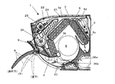
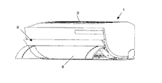
図1は本実施形態のセパレート型空気調和機における室内ユニットの暖房時の導風パネル開姿勢を示す断面図、図2は同じくその斜視図、図3は室内ユニットの冷房除湿時の導風パネル導風姿勢を示す断面図、図4は同じくその斜視図である。 FIG. 1 is a cross-sectional view showing an open position of a wind guide panel during heating of an indoor unit in a separate type air conditioner of the present embodiment, FIG. 2 is a perspective view thereof, and FIG. 3 is a wind guide panel during cooling and dehumidification of the indoor unit. Sectional drawing which shows a wind guide attitude | position, FIG. 4 is the perspective view similarly.
室内ユニット1は、図1及び図2に示すように、ケーシング2の上面に空気の吸込口3が形成され、ケーシング2の前面下部に空気の吹出口4が形成される。ケーシング2の内部には、吸込口3から吹出口4に至る内部空気通路が形成され、この内部空気通路に熱交換器5と室内ファン6とが配設される。
As shown in FIGS. 1 and 2, the
内部空気通路は、ケーシング上面の吸込口3から吸込んだ室内の空気をフィルタを通した後、熱交換器5で熱交換し、冷風又は温風として室内ファン6によって吹出口4から室内側に放出されるものである。この内部空気通路において、吹出口近傍で正負のイオンを放出し、この正負の除菌イオンを吹出される空気と共に室内に放出されるように、イオン発生装置45が吹出口4の近傍に設けられる。
In the internal air passage, after the indoor air sucked from the
室内ファン6は、クロスフローファンであって、その回転軸の軸方向が左右方向とされる。室内ファン6は、内部空気通路において熱交換器5よりも吹出口4側に配置される。
The
熱交換器5は、4つの熱交換器5a〜5dから構成され、これらのうち3つの熱交換器5a、5b、5cが前後および上側の三方から室内ファン6を囲むように配置される。後側に位置する熱交換器5cの背面側には、さらに一つの補助熱交換器5dが後側熱交換器5cと平行に配置される。各熱交換器5は、熱媒管と多数のフィンとから直方体形状に形成され、熱媒管の端部同士で他の熱交換器と接続され、冷凍サイクル107の一部を構成するようになっている。
The
また、後側の熱交換器5c、5dと前側の熱交換器5a、5bとの間に電磁弁115と減圧器112とが並列接続され、除湿運転時には、後ろ側の熱交換器5c、5dを凝縮器として使用し、前側の熱交換器5a,5bで湿気を除去した空気を、後ろ側熱交換器5c、5dの排熱を利用して暖められた空気と混合して吹出口4から放出する再熱除湿ができるようになっている。
In addition, the solenoid valve 115 and the pressure reducer 112 are connected in parallel between the
吸込口3に対面して吸込んだ室内の空気から塵埃を除去するフィルタ21が設けられる。フィルタ21は、極細繊維がネット状に編成又は織成され、吸込口3に対面して配置することにより、吸引した空気から塵や埃を除去できるようになっている。
A
このフィルタ21を清掃するフィルタ清掃装置22が設けられる。フィルタ清掃装置22は、ケーシング2の上面前側と前面上側と前側の熱交換器5a、5bとで囲まれた空間部に配置される。フィルタ清掃装置22は、ケーシング2内でフィルタ21を移動させる側面視でU字形に湾曲した移動案内路24と、該移動案内路24に面してフィルタに付着した塵埃を吸引除去する塵埃除去ボックス25と、フィルタ21を移動案内路24に沿って移動させる駆動手段26とを備え、吸引ファン(不図示)により、フィルタ21と略平行方向(左右方向)に空気を流すことで、フィルタ21に付着した塵埃を除去できるようになっている。また、塵埃除去ボックス内に回転ブラシを設け、フィルタ21に付着した塵埃を掻き取るようにしてもよい。
A
ケーシング2の左右方向の一側には、室内空気を吸込んで室外に排気する換気装置47が設けられる。この換気装置47は、カビ結露予防運転モードなどの各種運転モードで実行され、湿った空気を室外に排気する。
A
吹出口4には、縦ルーバ36aと横ルーバ36bとからなる風向変更装置36が設けられ、吹出口4から吹出す風の向きを変更することができるようになっている。また、風向変更装置36とは別に、ケーシング2の前面に覆い姿勢と導風姿勢に切換え自在な導風パネル7が設けられる。この導風パネル7は、吹出口4から吹出す空気を斜め上方向に導き、室内の天井に沿って遠方に空気に導くもので、導風パネル7の下端が第1の回動軸10周りに回動自在にケーシング2に軸支されている。
The
導風パネル7は、第1の回動軸10周りに回動により、吹出口4から略水平方向に配置されて吹出口4から吹出す空気を斜め上方向に導く導風姿勢と、ケーシング2の前面に沿って配置され、吹出口4を含むケーシングの前面の少なくとも下半分を覆う覆い姿勢とに切換え自在とされる。
The
また、導風パネル7は、主に吹出口4を覆うカバーパネル8と、該カバーパネル8の先端部に連続して設けられた延長パネル9とに分割される。カバーパネル8は延長パネル9に対して第2の回動軸11の周りに開閉回動自在に支持される。そして、カバーパネル8は、延長パネル9をケーシング2の前面に沿わせた覆い姿勢を保ちつつ、第2の回動軸11の周りの回動により、吹出口4を覆う閉姿勢と、下端が垂直方向に開いた開姿勢とに切り換え自在とされる。
The
カバーパネル8の開姿勢は、主として暖房運転時や局所的に冷風を吹出させたい急速冷房運転時に、吹出口4から吹出した風を下方に導くときに採用される。カバーパネル8は、図1に示すように、第2の回動軸11周りに回動して、「斜め下」、「下向き」、「真下」の姿勢をとることができる。
The open posture of the
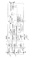
図5は空気調和機の構成ブロック図である。本実施形態の空気調和機は、室内ユニット1と室外ユニット101とに分離されたセパレート型のものである。
FIG. 5 is a configuration block diagram of the air conditioner. The air conditioner of this embodiment is a separate type that is separated into an
室内ユニット1は、空調すべき室内に設置されるもので、冷凍サイクル107の室内熱交換器5a〜5dと、例えばキャピラリーチューブや絞り弁などの減圧器112と、減圧器112をバイパスする開閉弁(電磁弁)115と、イオン発生装置45と、室内ファン6とを備えている。また、室内ユニット1には、室内の湿度を検知する湿度センサ116、室内の温度を検知する室内温度センサ117、制御部118、メモリ119、受信部120、およびタイマ121を有する。
The
室外ユニット101は、屋外に設置されるもので、冷凍サイクル107を構成する圧縮機108、室外熱交換器109、四方弁110、及び膨張弁を用いた減圧器111を有する。また、冷凍サイクルを制御するための室外制御部104や外気温度センサ105を有する。
The
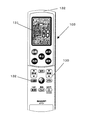
また、図6に示すように、室外ユニット11及び室内ユニット12とは別にリモートコントローラ103(以下、リモコン103と略称する)が設けられている。リモコン103には、各種設定や各種指令を行うスイッチ類を有する操作部130と、運転状況などを表示する表示部131と、室内ユニットの受信部120との間で送信を行う送信部132とを備えている。また、リモコン103は時計機能を備えており、表示部131に時刻を表示できるようになっている。
Further, as shown in FIG. 6, a remote controller 103 (hereinafter abbreviated as a remote controller 103) is provided separately from the
操作部130のスイッチ類のうち、一つの指令スイッチ132には、カビ結露予防運転を指示する指令スイッチと、衣類乾燥運転を指示する指令スイッチとが兼用される。この兼用する指令スイッチ132は、その押圧動作ごとに、カビ結露予防運転指令と衣類乾燥運転指令とが交互に出力される。
Of the switches of the
なお、リモコン103の送信部132からカビ結露予防運転指令を送信するとき、同時に時刻信号が送信される。この時刻信号を受けて室内ユニット1側の制御部118では、現在時刻が特定時間帯か否かを判断することができる。まあ、現在時刻をタイマ121に取り込み、時計機能として使用している。
When transmitting the mold condensation prevention operation command from the
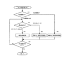
図7は本発明のカビ結露予防運転の制御フローチャートである。図7に示すように、リモコン103からカビ結露予防運転の開始指示が送信された場合、制御部118では、現在の運転状況を把握する(S1)。現在の運転モードが衣類乾燥運転モードの場合、カビ結露予防運転指令は、使用者から直ぐにカビ結露予防運転を実行することを所望する指令と判断することができるため、連続カビ結露予防運転を即実行する(S2)。
FIG. 7 is a control flowchart of the mold condensation prevention operation of the present invention. As shown in FIG. 7, when an instruction to start mold condensation prevention operation is transmitted from the
衣類乾燥運転モードでない場合、次に、タイマ121から現在時刻を読み込み、特定時間帯か否かを判断する(S3)。特定時間帯として、例えば、23:00〜7:00のいわゆる深夜時間帯の場合、深夜カビ結露予防運転を実行する(S5)。これにより、深夜電力を利用した運転により、使用料金も低減することができる。
If it is not in the clothes drying operation mode, the current time is read from the
しかし、特定時間帯以外でカビ結露予防指令を受けたとき、特定時間帯に突入するまでカビ結露予防運転を待機し(S4)、特定時間帯(例えば、23:00)に突入したときに、カビ結露予防運転を実行する。これにより、深夜電力利用による電力料金の低減を図る。 However, when the mold condensation prevention command is received outside the specific time zone, the mold condensation prevention operation is waited until entering the specific time zone (S4), and when entering the specific time zone (for example, 23:00), Perform mold condensation prevention operation. As a result, reduction of power charges due to the use of late-night power is planned.
なお、待機中は使用者に故障ではないかと誤解されるのを防ぐため、導風パネル7は閉状態であるが、運転ランプとタイマ−ランプを点灯し、使用者の不安感を解消する態様としている。
In order to prevent the user from misunderstanding that it is a failure during standby, the
そして、制御部118では、特定時間帯を経過したとき、例えば、7:00を経過したとき、カビ結露予防運転を中断し、次の特定時間帯(例えば、23:00)に入ったとき、カビ結露予防運転を再開する。そして、制御部118は、カビ結露予防運転のOFF信号や電源OFF信号、または、他の運転モード信号(冷房運転、暖房運転、単独換気運転などの信号)を受けるまで、上記サイクルを繰り返す。 Then, in the control unit 118, when a specific time zone has passed, for example, when 7:00 has passed, the mold condensation prevention operation is interrupted, and when the next specific time zone (for example, 23:00) is entered, Resume mold condensation prevention operation. And the control part 118 repeats the said cycle until it receives the OFF signal of a mold dew condensation prevention driving | operation, a power supply OFF signal, or another operation mode signal (signals, such as a cooling operation, a heating operation, and independent ventilation operation).
このように、本発明では、カビ結露予防指令を受けた場合でも、特定時間帯以外は待機し、特定時間帯でカビ結露予防運転を実行するので、特定時間帯として深夜時間帯を利用した場合、深夜電力利用により消費電力のコスト低減を実現することができる。 In this way, in the present invention, even when a mold condensation prevention command is received, standby is performed outside a specific time zone, and mold condensation prevention operation is performed in a specific time zone, so when using a midnight time zone as a specific time zone In addition, the cost reduction of power consumption can be realized by using midnight power.
なお、乾燥運転中にカビ結露予防運転指令を受けた場合、制御部118では、カビ結露運転を直ぐに実行するのは、リモコン103の指令スイッチ132が、カビ結露予防運転指令スイッチと衣類乾燥運転指令スイッチとを兼用しており、衣類乾燥運転中に同じ指令スイッチ132から指令信号を受けた場合、使用者がカビ結露予防運転を早急に実行することを要求しているものと判断できるので、特定時間帯に突入するまで待機することなく、カビ結露予防運転を即実行して使用者の要求に答えるようにしている。
When the mold condensation prevention operation command is received during the dry operation, the control unit 118 immediately executes the mold condensation prevention operation because the
ここで、衣類乾燥運転モードは、室内で効果的に洗濯物を乾かすことを目的とする運転で、外気温度と室内温度とにより、除湿主体の運転または暖房主体の運転モードが選択される。これらの除湿処理又は暖房処理と併せて、換気処理および殺菌処理が行われる。 Here, the clothes drying operation mode is an operation aimed at effectively drying the laundry indoors, and a dehumidifying operation or a heating operation mode is selected depending on the outside air temperature and the room temperature. A ventilation process and a sterilization process are performed together with these dehumidification processes or heating processes.
カビ結露予防運転モードでは、条件に応じて、殺菌及び除湿処理、殺菌及び暖房処理、殺菌・換気及び除湿処理、又は、殺菌・換気及び暖房処理を行う。 In the mold condensation prevention operation mode, sterilization and dehumidification processing, sterilization and heating processing, sterilization / ventilation and dehumidification processing, or sterilization / ventilation and heating processing are performed according to conditions.
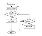
さらに、カビ結露予防運転は、図8に示すように、条件に応じてカビ予防運転モードと結露予防運転モードの2通りの運転モードに区分して実行することができる。例えば、図8に示すように、カビ結露予防運転指令を受け、カビ結露予防運転を実行するとき(S10)、制御部118では、カビ発生条件であるか否かを判断する(S11)。カビが発生しやすいのは湿度が60%以上であるので、制御部118では、湿度センサ116からの信号により湿度が60%以上か否かを判断し、湿度が60%以上のときにカビ予防運転を行い、湿度を下げる(S12)。このとき、イオン発生装置45及び換気装置47も併用運転してもよい。以下、特に限定しない限り、イオン発生装置45および換気装置47も併用運転しているものとして説明を続ける。
Further, as shown in FIG. 8, the mold condensation prevention operation can be executed by being classified into two operation modes of a mold prevention operation mode and a condensation prevention operation mode according to conditions. For example, as shown in FIG. 8, when the mold condensation prevention operation command is received and the mold condensation prevention operation is executed (S10), the control unit 118 determines whether or not the condition is a mold generation condition (S11). Mold tends to occur when the humidity is 60% or more. Therefore, the control unit 118 determines whether the humidity is 60% or more based on a signal from the
室内湿度が50%以下になった場合、乾燥空気により使用者に悪影響を及ぼさないよう、冷凍サイクルの運転を停止し待機状態に入る。このとき、室内ユニットの導風パネル7は閉状態で、イオン発生装置45および換気装置47は駆動し続け、また、室内ファン6は運転を続ける。
When the indoor humidity becomes 50% or less, the operation of the refrigeration cycle is stopped and a standby state is entered so that the user is not adversely affected by the dry air. At this time, the
一方、カビ発生条件でない場合、結露条件か否かを判断する(S13)。結露条件は、室内温度センサ117から入力した室内温度と外気温度センサ105からの入力した外気温度から窓温度(Twc)を予測し、室内空気の温度と湿度から室内空気の露点温度(Dpc)を計算する。そして、窓温度(Twc)と露点温度(Dpc)とを比較することにより、窓温度(Twc)が露点温度(Dpc)より低く結露しそうな状態であるか、又は、窓温度の方が高く結露の懸念がない状態であるかを判断する。この結果、結露条件に合致する場合、結露予防運転を実行する(S14)。 On the other hand, if it is not the mold generation condition, it is determined whether or not the condensation condition is satisfied (S13). As for the dew condensation condition, the window temperature (Twc) is predicted from the indoor temperature input from the indoor temperature sensor 117 and the outdoor air temperature input from the outdoor air temperature sensor 105, and the dew point temperature (Dpc) of the indoor air is determined from the temperature and humidity of the indoor air. calculate. Then, by comparing the window temperature (Twc) and the dew point temperature (Dpc), the window temperature (Twc) is likely to condense below the dew point temperature (Dpc), or the window temperature is higher than the dew point. Judge whether there is no concern. As a result, if the condensation conditions are met, the condensation prevention operation is executed (S14).
なお、除湿処理又は暖房処理を行う場合は、制御部118は、メモリ119に格納された第1湿度(例えば、60%)及び第2湿度(例えば、50%)、湿度センサ116が検知した室内の湿度、メモリ119に格納された所定室内温度(例えば、23度)および所定の外気温度(例えば、18度)、室内温度センサ117が検知した前記室内の温度、さらに外気温度センサ105が検知した外気の温度に基づいて、除湿処理を開始するか否か、除湿処理を停止するか否か、暖房処理を開始するか否か、または暖房処理を停止するか否かを判断する。
In addition, when performing a dehumidification process or a heating process, the control part 118 is the room | chamber interior which the 1st humidity (for example, 60%) and the 2nd humidity (for example, 50%) and
被処理空気は、室内ユニット1内で室内熱交換器5からフィルタを通して室内ファン6によって室内へ送風されるが、除湿処理として再熱除湿運転を行う場合、制御部118では、電磁弁115を閉じ、減圧器111を全開するように制御する。このため、主として減圧器112が減圧器として作用し、室内ユニット1の室内熱交換器5c、5dと室外ユニット101にある室外熱交換器109とが、凝縮器として作用する。
The air to be treated is blown into the room by the
このとき、冷凍サイクル107内の冷媒が、圧縮機108の吐出口、室外熱交換器109、(減圧器111)、室内熱交換器5c、5d、減圧器112、室内熱交換器5a,5b、及び圧縮機108の吸入口の順に循環するよう、四方弁110が切り換えられる。さらに、室外制御部104に制御されて、室外ファン106が駆動される。
At this time, the refrigerant in the refrigeration cycle 107 is discharged from the
冷媒は、減圧器112によって減圧され、低圧の液体となって室内熱交換器5a,5bへ送られ、室内熱交換器5a、5b内で周囲の熱を吸収して気化する。低圧の気体となった冷媒は圧縮機108へ送られ、圧縮されて高温高圧の気体となり、室外熱交換器109及び室内熱交換器5c、5dへ送られる。高温高圧の気体となった冷媒は、室外熱交換器109においては、室外ファン106の吸引力によって室外ユニット内に取り込まれて室外熱交換器109に接触した外気と熱交換され、また、室内熱交換器5c、5dにおいては、室内ファン6の吸引力によって室内ユニットに取り込まれて室内熱交換器5c、5dに接触した被処理空気と熱交換されて凝縮し、高圧の液体となって、前記減圧器112へ送られる。
The refrigerant is decompressed by the decompressor 112, is converted into a low-pressure liquid, is sent to the
そして、室内ユニットの前側に位置する室内熱交換器5a、5bに接触した被処理空気は、室内熱交換器5a、5b内の冷媒が被処理空気の熱を吸収することによって冷却され、前記被処理空気に含有される水分が室内熱交換器5a、5bの表面に結露して除湿される。また、室内ユニットの後ろ側の室内熱交換器5c、5dに接触した被処理空気は、室内熱交換器5c、5d内の冷媒と熱交換することによって加熱される。冷却及び除湿された被処理空気と加熱された被処理空気とが混合され、混合された被処理空気は、室内ファン6によって室内へ送風される。
And the to-be-processed air which contacted the
また、室外熱交換器109で冷媒と熱交換されて温度が上がった外気は、室外ファン106によって室外ユニットの外部へ排出される。
Further, the outdoor air whose temperature has been increased by heat exchange with the refrigerant in the
暖房処理を行う場合、制御部118は、冷凍サイクル107を制御して用いる。このとき、制御部118及び室外制御部104は、電磁弁115を開き、膨張弁である減圧器111の開度を制御して、冷凍サイクル107を用いるため、電磁弁115によって減圧器112がバイパスされて作用しなくなり、該減圧器112の代わりに減圧器111が作用する。
When performing the heating process, the control unit 118 controls and uses the refrigeration cycle 107. At this time, the control unit 118 and the
また、暖房処理では、冷凍サイクル107の冷媒が、圧縮機108の吐出口、室内熱交換器5a,5b、電磁弁115、室内熱交換器5c、5d、減圧器111、室外熱交換器109、及び圧縮機108の吸入口の順に循環するよう四方弁110が切り換えられる。さらに、該室外制御部104に制御されて、室外ファン106が駆動される。
In the heating process, the refrigerant of the refrigeration cycle 107 is discharged from the
冷媒は、減圧器111によって減圧され、低圧の液体となって室外熱交換器109へ送られ、該室外熱交換器109内で、室外送風機106の吸引力によって室外ユニット内に取り込まれて室外熱交換器109に接触した外気と熱交換され、周囲の熱を吸収して気化する。低圧の気体となった冷媒は圧縮機108へ送られ、圧縮されて高温高圧の気体となり、室内熱交換器5a,5b及び室内熱交換器5c、5dへ送られる。高温高圧の気体となった冷媒は、室内熱交換器5a,5b及び室内熱交換器5c、5d内で、送風ファン6の吸引力によって室内ユニットに取り込まれて室内熱交換器5a,5b及び室内熱交換器5c、5dに接触した被処理空気と熱交換されて凝縮し、高圧の液体となって、前記減圧器111へ送られる。
The refrigerant is depressurized by the decompressor 111 and is sent to the
室内熱交換器5に接触した被処理空気は、室内熱交換器5内の冷媒が放熱することによって加熱され、温度が上昇する。加熱された被処理空気は送風ファン6によって室内へ送風され、室内を暖房する。室内が暖房されることにより、室内の被処理空気の相対湿度は下がるため、カビ結露予防効果を発揮する。暖房処理を行わない場合は、制御部は冷凍サイクル107の運転を行わない。
The to-be-processed air which contacted the
なお、殺菌処理を行う場合、制御部118は、イオン発生装置45を制御する。このとき、被処理空気は、送風ファン6近傍に設けられたイオン発生装置45によって、室内の空気を殺菌するために充分な量の正イオン及び負イオンを付加され、室内ファン6によって室内へ送風されて、浮遊細菌又は微生物等を殺菌する。
In addition, when performing a sterilization process, the control part 118 controls the
換気処理を行う場合、制御部118は、換気装置47の吸引ファンを制御して室内空気を吸引し、外部に排気する。
When performing the ventilation process, the control unit 118 controls the suction fan of the
ここで、カビ結露予防運転において、再熱除湿処理を行うか、暖房処理を行うかは図9に示すような条件で行う。つまり、外気温度が18度以上で、室内温度が23度以上の場合には、再熱除湿運転を行う。これにより、室温を低下させることなく除湿することができる。また、外気温度が18度未満、または、室内温度が23度未満の場合は、使用者が寒さを感じないように暖房運転を行う。 Here, in the mold condensation prevention operation, whether the reheat dehumidification process or the heating process is performed is performed under the conditions shown in FIG. That is, when the outside air temperature is 18 degrees or higher and the room temperature is 23 degrees or higher, the reheat dehumidifying operation is performed. Thereby, dehumidification can be performed without lowering the room temperature. When the outside air temperature is less than 18 degrees or the room temperature is less than 23 degrees, the heating operation is performed so that the user does not feel cold.
1 室内ユニット
2 ケーシング
3 吸込口
4 吹出口
5 熱交換器
6 室内ファン
7 導風パネル
8 カバーパネル
9 延長パネル
10 第1回動軸
11 第2回動軸
45 イオン発生装置
47 換気装置
103 リモコン
104 室外制御部
105 外気温度センサ
107 冷凍サイクル
108 圧縮機
109 室外熱交換器
110 四方弁
111 減圧器
112 減圧器
115 電磁弁
116 湿度センサ
117 室内温度センサ
118 制御部
119 メモリ
120 受信部
121 タイマ
130 操作部
131 表示部
132 送信部
DESCRIPTION OF
Claims (3)
Priority Applications (1)
| Application Number | Priority Date | Filing Date | Title |
|---|---|---|---|
| JP2007106110A JP4938536B2 (en) | 2007-04-13 | 2007-04-13 | Air conditioner |
Applications Claiming Priority (1)
| Application Number | Priority Date | Filing Date | Title |
|---|---|---|---|
| JP2007106110A JP4938536B2 (en) | 2007-04-13 | 2007-04-13 | Air conditioner |
Publications (3)
| Publication Number | Publication Date |
|---|---|
| JP2008261602A JP2008261602A (en) | 2008-10-30 |
| JP2008261602A5 JP2008261602A5 (en) | 2009-12-03 |
| JP4938536B2 true JP4938536B2 (en) | 2012-05-23 |
Family
ID=39984208
Family Applications (1)
| Application Number | Title | Priority Date | Filing Date |
|---|---|---|---|
| JP2007106110A Active JP4938536B2 (en) | 2007-04-13 | 2007-04-13 | Air conditioner |
Country Status (1)
| Country | Link |
|---|---|
| JP (1) | JP4938536B2 (en) |
Cited By (1)
| Publication number | Priority date | Publication date | Assignee | Title |
|---|---|---|---|---|
| CN103239943A (en) * | 2013-05-14 | 2013-08-14 | 陈朝阳 | Solid-containing vapor-state substance separation device |
Families Citing this family (3)
| Publication number | Priority date | Publication date | Assignee | Title |
|---|---|---|---|---|
| JP2020060314A (en) * | 2018-10-10 | 2020-04-16 | パナソニックIpマネジメント株式会社 | Air conditioner |
| JP2022061413A (en) * | 2020-10-06 | 2022-04-18 | パナソニックIpマネジメント株式会社 | Air conditioner and method for controlling air conditioner |
| CN115751584B (en) * | 2022-09-08 | 2024-09-03 | 珠海格力电器股份有限公司 | Control method and control device for mildew-proof drying of air conditioner and air conditioning system |
Family Cites Families (5)
| Publication number | Priority date | Publication date | Assignee | Title |
|---|---|---|---|---|
| JPH02169944A (en) * | 1988-12-21 | 1990-06-29 | Matsushita Seiko Co Ltd | Method of controlling air conditioner |
| JP2000274771A (en) * | 1999-03-24 | 2000-10-06 | Seiko Sangyo:Kk | Automatic ventilator and long time timer used therefor |
| JP2002267234A (en) * | 2001-03-12 | 2002-09-18 | Matsushita Electric Ind Co Ltd | Control device for air conditioner |
| JP2002277029A (en) * | 2001-03-22 | 2002-09-25 | Toto Ltd | Air conditioning system and method for controlling air conditioning |
| JP2003042510A (en) * | 2001-08-02 | 2003-02-13 | Corona Corp | Dehumidifier |
-
2007
- 2007-04-13 JP JP2007106110A patent/JP4938536B2/en active Active
Cited By (2)
| Publication number | Priority date | Publication date | Assignee | Title |
|---|---|---|---|---|
| CN103239943A (en) * | 2013-05-14 | 2013-08-14 | 陈朝阳 | Solid-containing vapor-state substance separation device |
| CN103239943B (en) * | 2013-05-14 | 2015-09-23 | 陈朝阳 | Solid-containing vapor-state substance separation device |
Also Published As
| Publication number | Publication date |
|---|---|
| JP2008261602A (en) | 2008-10-30 |
Similar Documents
| Publication | Publication Date | Title |
|---|---|---|
| JP5975937B2 (en) | Air conditioner | |
| JP6922954B2 (en) | Air conditioning system | |
| CN114341556B (en) | Air conditioning system | |
| JP4938536B2 (en) | Air conditioner | |
| JP2010078254A (en) | Air conditioner | |
| JP4417709B2 (en) | Air conditioner | |
| JP7082269B2 (en) | air conditioner | |
| KR100561136B1 (en) | Air conditioner | |
| JP7148808B2 (en) | air conditioning system | |
| JP2003322359A (en) | Air conditioner | |
| JP2006162173A (en) | Air conditioner | |
| JP3731113B2 (en) | Air conditioner | |
| JPH0336433A (en) | Air conditioner | |
| JP2005016830A (en) | Air-conditioner | |
| JP2002188843A (en) | Outdoor air treating unit | |
| JP2007285566A (en) | Air conditioner | |
| JP6989780B2 (en) | Air conditioner | |
| JP7199051B2 (en) | indoor air conditioning system | |
| JP2009299983A (en) | Air conditioner | |
| JP2008116136A (en) | Air conditioner | |
| JP4683056B2 (en) | Air conditioner indoor unit | |
| JPH06123469A (en) | Operation controller for dehumidifying unit with air conditioning and ventilating function | |
| WO2022004264A1 (en) | Heat exchange ventilation device with air purification function | |
| CN115885134B (en) | Indoor air conditioning system | |
| JP6171410B2 (en) | Air conditioner |
Legal Events
| Date | Code | Title | Description |
|---|---|---|---|
| A521 | Written amendment |
Free format text: JAPANESE INTERMEDIATE CODE: A523 Effective date: 20091021 |
|
| A621 | Written request for application examination |
Free format text: JAPANESE INTERMEDIATE CODE: A621 Effective date: 20091021 |
|
| A977 | Report on retrieval |
Free format text: JAPANESE INTERMEDIATE CODE: A971007 Effective date: 20110713 |
|
| A131 | Notification of reasons for refusal |
Free format text: JAPANESE INTERMEDIATE CODE: A131 Effective date: 20110726 |
|
| A521 | Written amendment |
Free format text: JAPANESE INTERMEDIATE CODE: A523 Effective date: 20110921 |
|
| TRDD | Decision of grant or rejection written | ||
| A01 | Written decision to grant a patent or to grant a registration (utility model) |
Free format text: JAPANESE INTERMEDIATE CODE: A01 Effective date: 20120131 |
|
| A01 | Written decision to grant a patent or to grant a registration (utility model) |
Free format text: JAPANESE INTERMEDIATE CODE: A01 |
|
| A61 | First payment of annual fees (during grant procedure) |
Free format text: JAPANESE INTERMEDIATE CODE: A61 Effective date: 20120223 |
|
| FPAY | Renewal fee payment (event date is renewal date of database) |
Free format text: PAYMENT UNTIL: 20150302 Year of fee payment: 3 |
|
| R150 | Certificate of patent or registration of utility model |
Ref document number: 4938536 Country of ref document: JP Free format text: JAPANESE INTERMEDIATE CODE: R150 Free format text: JAPANESE INTERMEDIATE CODE: R150 |