<第1実施形態>
(1)空調システム1の構成の概要
図1に示されているように、第1実施形態に係る空調システム1は、空調室内機2を備えている。空調システム1は、図3及び図5に示されているように、空調室内機2を制御する制御部8を備えている。空調室内機2は、部屋RMに対して設置され(図1参照)、部屋RMの中(室内)の空気調和を行う。第1実施形態では、空調室内機2が部屋RMの壁WLに取り付けられて設置される場合について説明する。しかし、空調室内機2のタイプは、部屋RMの壁WLに設置されるタイプに限られるものではない。空調室内機2は、例えば、天井CEまたは床FLに設置されるものであってもよい。
<First embodiment>
(1) Overview of Configuration of Air Conditioning System 1 As shown in FIG. 1 , an air conditioning system 1 according to the first embodiment includes an air conditioning indoor unit 2 . The air conditioning system 1 includes a control unit 8 that controls the air conditioning indoor unit 2, as shown in FIGS. The air conditioner indoor unit 2 is installed in the room RM (see FIG. 1) and performs air conditioning in the room RM (indoor). 1st Embodiment demonstrates the case where the air conditioner indoor unit 2 is attached to the wall WL of the room|room RM, and is installed. However, the type of the air conditioning indoor unit 2 is not limited to the type installed on the wall WL of the room RM. The air conditioner indoor unit 2 may be installed, for example, on the ceiling CE or the floor FL.
空調室内機2は、図2に示されているように、室内熱交換器21と室内ファン22とを有している。空調室内機2は、室内熱交換器21に室内空気(部屋RMの中の空気)を通して室内空気の熱交換を行う。室内ファン22は、室内熱交換器21を通過する気流を発生させる。言い換えると、室内ファン22は、室内空気を室内熱交換器21に供給する。室内熱交換器21は、複数の伝熱フィン21aと複数の伝熱管21bとを有している。室内空気は、複数の伝熱フィン21aの間を通過する。また、熱交換の際には、複数の伝熱フィン21aの間を空気が通過すると同時に、伝熱管21bの中を冷媒が流れる。伝熱管21bは、複数折り返されていて1つの伝熱フィン21aを複数回貫通する。
The air conditioning indoor unit 2 has an indoor heat exchanger 21 and an indoor fan 22, as shown in FIG. The air conditioning indoor unit 2 passes indoor air (air in the room RM) through the indoor heat exchanger 21 to perform heat exchange of the indoor air. The indoor fan 22 generates airflow passing through the indoor heat exchanger 21 . In other words, the indoor fan 22 supplies indoor air to the indoor heat exchanger 21 . The indoor heat exchanger 21 has a plurality of heat transfer fins 21a and a plurality of heat transfer tubes 21b. Indoor air passes between the plurality of heat transfer fins 21a. During heat exchange, the air passes through the heat transfer fins 21a and the refrigerant flows through the heat transfer tubes 21b. The heat transfer tube 21b is folded multiple times and penetrates one heat transfer fin 21a multiple times.
空調システム1は、空調室内機2の他に、図1及び図3に示されている加湿器6を備えている。加湿器6は、部屋RMの中(室内)に水分を供給して、室内の湿度を上げる加湿を行う。
The air conditioning system 1 includes a humidifier 6 shown in FIGS. 1 and 3 in addition to the air conditioning indoor unit 2 . The humidifier 6 supplies water to the inside of the room RM (inside the room) to perform humidification to raise the humidity in the room.
空調システム1は、図3及び図5に示されているように、空調室内機2と加湿器6とを制御する制御部8を備えている。空調システム1は、運転モードとして、通常モードと洗浄モードを有している。制御部8は、通常モードでは、室内の空気調和を行うように空調室内機2を制御する。制御部8は、洗浄モードでは、室内熱交換器21の洗浄を行うように空調室内機2を制御する。また、洗浄モードでは、室内熱交換器21の洗浄のために、加湿器6を制御する。
The air conditioning system 1 includes a control unit 8 that controls the air conditioning indoor unit 2 and the humidifier 6, as shown in FIGS. The air conditioning system 1 has a normal mode and a cleaning mode as operation modes. In the normal mode, the control unit 8 controls the air conditioner indoor unit 2 so as to perform indoor air conditioning. In the cleaning mode, the controller 8 controls the air conditioning indoor unit 2 to clean the indoor heat exchanger 21 . In the cleaning mode, the humidifier 6 is controlled for cleaning the indoor heat exchanger 21 .
制御部8は、室内ファン22の駆動時間をカウントする。制御部8は、空調室内機2の制御において室内ファン22の駆動と停止を指示する。そのために、制御部8は、タイマ81aを有している。従って、制御部8は、タイマ81aによって、室内ファン22の駆動時間をカウントすることができる。ただし、制御部8が室内ファン22の駆動時間をカウントする方法は、タイマ81aによる方法に限られるものではない。
The controller 8 counts the driving time of the indoor fan 22 . The control unit 8 instructs to drive and stop the indoor fan 22 in controlling the air conditioning indoor unit 2 . Therefore, the controller 8 has a timer 81a. Therefore, the controller 8 can count the driving time of the indoor fan 22 by the timer 81a. However, the method by which the controller 8 counts the driving time of the indoor fan 22 is not limited to the method using the timer 81a.
制御部8は、例えば、マイクロコンピュータにより実現されるものである。制御部8は、例えば、制御演算装置81bと記憶装置81cとを備える。制御演算装置81bには、CPUまたはGPUといったプロセッサを使用できる。制御演算装置81bは、記憶装置81cに記憶されているプログラムを読み出し、このプログラムに従って、例えば所定のシーケンス処理及び演算処理を行う。さらに、制御演算装置81bは、プログラムに従って、演算結果を記憶装置81cに書き込んだり、記憶装置81cに記憶されている情報を読み出したりすることができる。記憶装置81cは、データベースとして用いることができる。
The control unit 8 is implemented by, for example, a microcomputer. The control unit 8 includes, for example, a control arithmetic device 81b and a storage device 81c. A processor such as a CPU or GPU can be used for the control arithmetic unit 81b. The control arithmetic device 81b reads a program stored in the storage device 81c, and performs, for example, predetermined sequence processing and arithmetic processing according to this program. Furthermore, the control arithmetic device 81b can write the arithmetic result to the storage device 81c and read the information stored in the storage device 81c according to the program. The storage device 81c can be used as a database.
制御部8は、例えば、制御演算装置81bにより室内ファン22の駆動時間を積算して、得られた積算駆動時間を記憶装置81cに書き込む。制御部8は、記憶装置81cに記憶されている積算駆動時間に基づいて、制御演算装置81bを用いて、洗浄モードによる制御を行うか否かを判断する。
For example, the control unit 8 integrates the driving time of the indoor fan 22 using the control arithmetic device 81b, and writes the obtained integrated driving time in the storage device 81c. Based on the cumulative drive time stored in the storage device 81c, the control section 8 uses the control arithmetic device 81b to determine whether or not to perform control in the cleaning mode.
空調システム1は、積算駆動時間に基づいて洗浄モードによる制御を行うか否かを判断することにより、適切なタイミングで室内熱交換器21を洗浄することができる。
The air conditioning system 1 can clean the indoor heat exchanger 21 at appropriate timing by determining whether or not to perform control in the cleaning mode based on the cumulative driving time.
(2)詳細構成
(2-1)全体構成
空調室内機2は、空調システム1の空気調和機10が有している。空気調和機10は、空調室内機2の他に、図1及び図2に示されている空調室外機4とリモートコントローラ15とを有している。空調室内機2と空調室外機4とは、冷媒連絡管11,12で接続されている。空調室内機2と空調室外機4と冷媒連絡管11,12とは冷媒回路13を構成している。空調室内機2と空調室外機4は、制御部8により制御される。冷媒回路13では、例えば、冷房運転、暖房運転及び除湿運転の際に、蒸気圧縮式冷凍サイクルが繰り返される。
(2) Detailed Configuration (2-1) Overall Configuration The air conditioning indoor unit 2 is included in the air conditioner 10 of the air conditioning system 1 . The air conditioner 10 has an air conditioner outdoor unit 4 and a remote controller 15 shown in FIGS. 1 and 2 in addition to the air conditioner indoor unit 2 . The air conditioner indoor unit 2 and the air conditioner outdoor unit 4 are connected by refrigerant communication pipes 11 and 12 . The air conditioning indoor unit 2 , the air conditioning outdoor unit 4 , and the refrigerant communication pipes 11 and 12 form a refrigerant circuit 13 . The air conditioning indoor unit 2 and the air conditioning outdoor unit 4 are controlled by the control unit 8 . In the refrigerant circuit 13, for example, the vapor compression refrigeration cycle is repeated during cooling operation, heating operation, and dehumidification operation.
(2-2)詳細構成
(2-2-1)空調室内機2
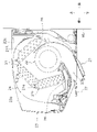
図2、図3及び図5に示されているように、空調室内機2は、室内熱交換器21と、室内ファン22と、ケーシング23と、エアフィルタ24と、ドレンパン26と、水平フラップ27と、垂直フラップ(図示せず)と、放電ユニット29とを備えている。また、空調室内機2は、室内温度センサ31と、室内湿度センサ32と、ダクト用温度センサ33と、ダクト用湿度センサ34と、室内熱交換器温度センサ35とを備えている。
(2-2) Detailed configuration (2-2-1) Air conditioning indoor unit 2
As shown in FIGS. 2, 3, and 5, the air conditioning indoor unit 2 includes an indoor heat exchanger 21, an indoor fan 22, a casing 23, an air filter 24, a drain pan 26, and a horizontal flap 27. , a vertical flap (not shown) and a discharge unit 29 . The air conditioner indoor unit 2 also includes an indoor temperature sensor 31 , an indoor humidity sensor 32 , a duct temperature sensor 33 , a duct humidity sensor 34 , and an indoor heat exchanger temperature sensor 35 .
以下の説明では、図1及び図2に矢印で示されている向きに従って、「上」、「下」、「前」、「後」という表現を用いて、方向を説明する場合がある。
In the following description, directions may be described using the expressions "up", "down", "front", and "back" according to the directions indicated by the arrows in FIGS. 1 and 2 .
ケーシング23は、上部に、吸込口23aを有し、下部に、吹出口23bを有している。空調室内機2は、室内ファン22を駆動して、室内の空気を吸込口23aから吸込み、室内熱交換器21を通過した空気を吹出口23bから吹き出す。
The casing 23 has a suction port 23a at its upper portion and an outlet port 23b at its lower portion. The air conditioning indoor unit 2 drives the indoor fan 22 to suck in indoor air from the suction port 23a, and blow out the air that has passed through the indoor heat exchanger 21 from the blowout port 23b.
室内ファン22は、空調室内機2の断面視において(図2参照)、ケーシング23の中の略中央部分に配置されている。室内ファン22は、例えば、クロスフローファンである。吸込口23aから吹出口23bに向う空気流路において、室内ファン22の上流に室内熱交換器21が配置されている。室内熱交換器21は、伝熱管21bの延びる方向に見て、室内ファン22の上方を覆うように、下に向って開いた形状を呈する。ここでは、このような形状を略Λ形状と呼ぶ。室内熱交換器21は、壁WLから遠い第1熱交換部21Fと壁WLに近い第2熱交換部21Rを有している。
The indoor fan 22 is arranged in a substantially central portion within the casing 23 in a cross-sectional view of the air conditioning indoor unit 2 (see FIG. 2). The indoor fan 22 is, for example, a cross-flow fan. The indoor heat exchanger 21 is arranged upstream of the indoor fan 22 in the air flow path from the suction port 23a to the blowout port 23b. The indoor heat exchanger 21 has a downwardly open shape so as to cover the upper part of the indoor fan 22 when viewed in the direction in which the heat transfer tubes 21b extend. Here, such a shape is called a substantially Λ shape. The indoor heat exchanger 21 has a first heat exchange section 21F far from the wall WL and a second heat exchange section 21R close to the wall WL.
略Λ形状を持つ室内熱交換器21の前方下部及び後方下部の下に、ドレンパン26が配置されている。室内熱交換器21のうちの第1熱交換部21Fで発生した結露は、室内熱交換器21の前方下部に配置されているドレンパン26で受け止められる。室内熱交換器21のうちの第2熱交換部21Rで発生した結露は、室内熱交換器21の後方下部に配置されているドレンパン26で受け止められる。
Drain pans 26 are arranged under the front lower portion and the rear lower portion of the indoor heat exchanger 21 having a substantially Λ shape. Condensation generated in the first heat exchange section 21</b>F of the indoor heat exchanger 21 is received by the drain pan 26 arranged in the lower front portion of the indoor heat exchanger 21 . Condensation generated in the second heat exchange section 21R of the indoor heat exchanger 21 is received by the drain pan 26 arranged in the lower rear portion of the indoor heat exchanger 21 .
吹出口23bには、水平フラップ27及び垂直フラップが配置されている。水平フラップ27は、吹出口23bから吹出される空気の風向を上下に変更する。そのため、水平フラップ27は、モータ27mにより、水平方向とのなす角を変更することができるように構成されている。垂直フラップは、吹出口23bから吹出される空気の風向を左右に変更することができるように構成されている。空調システム1は、例えば、垂直フラップをモータ(図示せず)で前後方向とのなす角を変更するように駆動する。
A horizontal flap 27 and a vertical flap are arranged at the outlet 23b. The horizontal flap 27 vertically changes the direction of the air blown from the outlet 23b. Therefore, the horizontal flap 27 is configured so that the angle formed with the horizontal direction can be changed by a motor 27m. The vertical flap is configured to be able to change the direction of the air blown out from the outlet 23b to the left or right. The air conditioning system 1 drives, for example, a vertical flap with a motor (not shown) so as to change the angle formed with the front-rear direction.
ケーシング23の中の吸込口23aの下流且つ室内熱交換器21の上流には、エアフィルタ24が配置されている。室内熱交換器21に供給される室内空気が実質的に全てエアフィルタ24を通過するように、エアフィルタ24は、ケーシング23に設置されている。従って、エアフィルタ24の網目よりも大きな塵埃は、エアフィルタ24で除去されるので室内熱交換器21には到達しない。しかし、エアフィルタ24の網目よりも細かい塵埃及びオイルミストなど、エアフィルタ24を通過するものは室内熱交換器21に到達する。
An air filter 24 is arranged downstream of the suction port 23 a in the casing 23 and upstream of the indoor heat exchanger 21 . The air filter 24 is installed in the casing 23 so that substantially all of the indoor air supplied to the indoor heat exchanger 21 passes through the air filter 24 . Therefore, dust larger than the mesh of the air filter 24 is removed by the air filter 24 and does not reach the indoor heat exchanger 21 . However, what passes through the air filter 24 , such as dust and oil mist finer than the mesh of the air filter 24 , reaches the indoor heat exchanger 21 .
放電ユニット29は、内部に放電部を有して構成された活性種生成装置である。放電部は、例えば、針状電極と対向電極とを備え、高電圧を印加することによりプラズマ放電の一種であるストリーマ放電を発生させる。酸化分解力の高い活性種は、放電発生の際に生成される。これらの活性種には、例えば、高速電子、イオン、水酸化ラジカル及び励起酸素分子が含まれる。活性種は、例えば、アンモニア類、アルデヒド類、窒素酸化物等の小さな有機分子からなる空気中の有害成分及び臭気成分を分解する。放電ユニット29は、例えば、エアフィルタ24の上流、または室内熱交換器21の上流に配置される。
The discharge unit 29 is an active species generator having a discharge section inside. The discharge section includes, for example, a needle-like electrode and a counter electrode, and applies a high voltage to generate a streamer discharge, which is a type of plasma discharge. Active species with high oxidative decomposition power are generated when discharge occurs. These active species include, for example, fast electrons, ions, hydroxyl radicals and excited oxygen molecules. The active species decompose harmful and odorous components in the air consisting of small organic molecules such as ammonia, aldehydes, and nitrogen oxides. The discharge unit 29 is arranged, for example, upstream of the air filter 24 or upstream of the indoor heat exchanger 21 .
空調室内機2の中には、制御部8を構成している室内制御板81が配置されている。図5に示されているように、室内制御板81は、室内ファン22のモータ22m、水平フラップ27のモータ27m及び電磁弁28に接続されている。制御部8は、室内制御板81により、室内ファン22のモータ22mの回転数、水平フラップのモータ27mの回転角度及び電磁弁28のオンオフを制御することができる。室内制御板81は、タイマ81aと制御演算装置81bと記憶装置81cとを有している。室内制御板81は、空調室外機4の中に配置されている室外制御板82(図3及び図5参照)に接続されている。ここでは、タイマ81aと制御演算装置81bと記憶装置81cとを室内制御板81が有している場合について説明するが、タイマ81aと制御演算装置81bと記憶装置81cとは、制御部8の他の箇所に設けられてもよい。例えば、タイマ81aと制御演算装置81bと記憶装置81cとは、室外制御板82に設けられてもよい。
An indoor control plate 81 constituting the control unit 8 is arranged in the air conditioning indoor unit 2 . As shown in FIG. 5, the indoor control plate 81 is connected to the motor 22m of the indoor fan 22, the motor 27m of the horizontal flap 27, and the electromagnetic valve 28. As shown in FIG. The controller 8 can control the number of revolutions of the motor 22m of the indoor fan 22, the rotation angle of the motor 27m of the horizontal flap, and the ON/OFF of the electromagnetic valve 28 by the indoor control plate 81. FIG. The indoor control board 81 has a timer 81a, a control arithmetic device 81b, and a storage device 81c. The indoor control plate 81 is connected to an outdoor control plate 82 (see FIGS. 3 and 5) arranged inside the air conditioner outdoor unit 4 . Here, a case where the indoor control board 81 has a timer 81a, a control arithmetic device 81b, and a storage device 81c will be described. may be provided at the location of For example, the timer 81a, the control arithmetic device 81b, and the storage device 81c may be provided on the outdoor control board 82. FIG.
制御部8は、リモートコントローラ15からの信号を室内制御板81が受信して、リモートコントローラ15から入力される指示を受け取る。リモートコントローラ15は、表示画面15aを有している。制御部8は、リモートコントローラ15の表示画面15aに種々の情報を表示することができる。制御部8は、例えば、表示画面15aを使って、洗浄動作ができないことを報知することができる。
In the control unit 8 , the indoor control panel 81 receives a signal from the remote controller 15 and receives an instruction input from the remote controller 15 . The remote controller 15 has a display screen 15a. The control unit 8 can display various information on the display screen 15 a of the remote controller 15 . The control unit 8 can notify that the cleaning operation cannot be performed, for example, using the display screen 15a.
図3及び図5には、空調室内機2が備えるセンサのうち、室内温度センサ31と、室内湿度センサ32と、ダクト用温度センサ33と、ダクト用湿度センサ34と、室内熱交換器温度センサ35が示されている。空調室内機2が備えるこれらのセンサは、室内制御板81に接続されている。従って、制御部8は、室内温度センサ31により室内の空気の温度を検知することができ、室内湿度センサ32により室内の空気の相対湿度を検知することができる。制御部8は、ダクト用温度センサ33により加湿器6から空調室内機2に吹出される空気の温度を検知でき、ダクト用湿度センサ34により加湿器6から空調室内機2に吹出される空気の相対湿度を検知できる。また、制御部8は、室内熱交換器温度センサ35により室内熱交換器21の特定の場所を流れる冷媒の温度を検知できる。この特定の場所は、例えば室内熱交換器温度センサ35が取り付けられている伝熱管21bの箇所である。
3 and 5 show, of the sensors included in the air conditioning indoor unit 2, an indoor temperature sensor 31, an indoor humidity sensor 32, a duct temperature sensor 33, a duct humidity sensor 34, and an indoor heat exchanger temperature sensor. 35 are shown. These sensors included in the air conditioner indoor unit 2 are connected to the indoor control board 81 . Therefore, the controller 8 can detect the temperature of the air in the room with the room temperature sensor 31 and the relative humidity of the air in the room with the room humidity sensor 32 . The control unit 8 can detect the temperature of the air blown from the humidifier 6 to the air conditioner indoor unit 2 by the duct temperature sensor 33, and detect the temperature of the air blown from the humidifier 6 to the air conditioner indoor unit 2 by the duct humidity sensor 34. Can detect relative humidity. In addition, the controller 8 can detect the temperature of the refrigerant flowing through a specific location of the indoor heat exchanger 21 using the indoor heat exchanger temperature sensor 35 . This specific location is, for example, the location of the heat transfer tube 21b to which the indoor heat exchanger temperature sensor 35 is attached.
図3に示されているように、室内熱交換器21は、電磁弁28を有している。室外膨張弁45から室内熱交換器21の他方の出入口に流れ込む冷媒は、第1熱交換部21Fから電磁弁28を通って第2熱交換部21Rに流れる。逆に、四方弁42の第4ポートP4から室内熱交換器21の一方の出入口に流れ込む冷媒は、第2熱交換部21Rから電磁弁28を通って第1熱交換部21Fに流れる。電磁弁28は、第1熱交換部21Fと第2熱交換部21Rとの間に差圧を設定する弁である。ここでは、電磁弁28を用いる場合について説明するが、例えば弁開度を変更できる電動弁などの他の制御弁を用いてもよい。電磁弁28は、オフ状態のときよりもオン状態のときに開度が小さくなるように設定されている。言い換えると、電磁弁28は、オン状態のときに、第1熱交換部21Fと第2熱交換部21Rとの間の差圧を大きくする。
As shown in FIG. 3 , the indoor heat exchanger 21 has an electromagnetic valve 28 . The refrigerant flowing from the outdoor expansion valve 45 to the other inlet/outlet of the indoor heat exchanger 21 flows from the first heat exchange section 21F through the solenoid valve 28 to the second heat exchange section 21R. Conversely, the refrigerant flowing from the fourth port P4 of the four-way valve 42 into one inlet/outlet of the indoor heat exchanger 21 flows from the second heat exchange section 21R through the solenoid valve 28 to the first heat exchange section 21F. The solenoid valve 28 is a valve that sets a differential pressure between the first heat exchange section 21F and the second heat exchange section 21R. Here, the case where the electromagnetic valve 28 is used will be described, but other control valves such as an electrically operated valve that can change the degree of valve opening may be used. The solenoid valve 28 is set so that the degree of opening is smaller in the ON state than in the OFF state. In other words, the solenoid valve 28 increases the differential pressure between the first heat exchange section 21F and the second heat exchange section 21R when in the ON state.
(2-2-2)空調室外機4
空調室外機4は、図3及び図5に示されているように、圧縮機41と四方弁42とアキュムレータ43と室外熱交換器44と室外膨張弁45と室外ファン46とケーシング47とを備えている。圧縮機41と四方弁42とアキュムレータ43と室外熱交換器44と室外膨張弁45と室外ファン46とは、ケーシング47の中に収納されている。ケーシング47は、室外の空気を吸い込む吸込口47a(図3参照)と、熱交換後の空気を吹き出す吹出口47b(図1及び図3参照)とを有する。吸込口47aは、ケーシング47の後側に配置されている。空調室外機4は、空調室内機2に熱エネルギーを供給する熱源ユニットとして機能する。
(2-2-2) Air conditioner outdoor unit 4
3 and 5, the air conditioner outdoor unit 4 includes a compressor 41, a four-way valve 42, an accumulator 43, an outdoor heat exchanger 44, an outdoor expansion valve 45, an outdoor fan 46, and a casing 47. ing. Compressor 41 , four-way valve 42 , accumulator 43 , outdoor heat exchanger 44 , outdoor expansion valve 45 and outdoor fan 46 are housed in casing 47 . The casing 47 has a suction port 47a (see FIG. 3) for sucking outdoor air, and a blowout port 47b (see FIGS. 1 and 3) for blowing out air after heat exchange. The suction port 47 a is arranged on the rear side of the casing 47 . The air conditioner outdoor unit 4 functions as a heat source unit that supplies thermal energy to the air conditioner indoor unit 2 .
圧縮機41は、ガス冷媒を吸入して圧縮して吐出する。圧縮機41は、例えば、モータ41mの運転周波数をインバータにより調整することで運転容量を変更することができる可変容量圧縮機である。運転周波数が大きいほど圧縮機41の運転容量が大きくなる。四方弁42は、4つのポートを有している。四方弁42の第1ポートP1は、圧縮機41の吐出口に接続されている。四方弁42の第2ポートP2は、室外熱交換器44の一方の出入口に接続されている。四方弁42の第3ポートP3は、アキュムレータ43に接続されている。四方弁42の第4ポートP4は、室内熱交換器21の一方の出入口に接続されている。
The compressor 41 sucks, compresses, and discharges gas refrigerant. The compressor 41 is, for example, a variable capacity compressor whose operating capacity can be changed by adjusting the operating frequency of the motor 41m with an inverter. As the operating frequency increases, the operating capacity of the compressor 41 increases. The four-way valve 42 has four ports. A first port P<b>1 of the four-way valve 42 is connected to a discharge port of the compressor 41 . A second port P<b>2 of the four-way valve 42 is connected to one inlet/outlet of the outdoor heat exchanger 44 . A third port P3 of the four-way valve 42 is connected to the accumulator 43 . A fourth port P4 of the four-way valve 42 is connected to one inlet/outlet of the indoor heat exchanger 21 .
アキュムレータ43は、四方弁42の第3ポートP3と圧縮機41の吸入口との間に接続されている。室外熱交換器44は、他方の出入口を室外膨張弁45の一方の出入口に接続している。室外熱交換器44は、一方の出入口または他方の出入口から内部に流入した冷媒と、室外の空気との間で熱交換を行う。室外膨張弁45は、他方の出入口を室内熱交換器21の他方の出入口に接続している。
The accumulator 43 is connected between the third port P3 of the four-way valve 42 and the suction port of the compressor 41 . The outdoor heat exchanger 44 has the other inlet/outlet connected to one inlet/outlet of the outdoor expansion valve 45 . The outdoor heat exchanger 44 exchanges heat between the refrigerant that has flowed into the inside from one entrance or the other entrance and the outdoor air. The outdoor expansion valve 45 has the other inlet/outlet connected to the other inlet/outlet of the indoor heat exchanger 21 .
空調室外機4の中には、制御部8を構成している室外制御板82が配置されている。室外制御板82は、室内制御板81に接続されている。室外制御板82は、圧縮機41のモータ41m、四方弁42及び室外ファン46のモータ46mに接続されている。制御部8は、室外制御板82により、圧縮機41のモータ41mの運転周波数、四方弁42の開度及び室外ファン46のモータ46mの回転数を制御することができる。
An outdoor control plate 82 constituting the control unit 8 is arranged in the air conditioner outdoor unit 4 . The outdoor control plate 82 is connected to the indoor control plate 81 . The outdoor control plate 82 is connected to the motor 41 m of the compressor 41 , the four-way valve 42 and the motor 46 m of the outdoor fan 46 . The control unit 8 can control the operating frequency of the motor 41 m of the compressor 41 , the opening degree of the four-way valve 42 , and the rotation speed of the motor 46 m of the outdoor fan 46 with the outdoor control plate 82 .
図3及び図5には、空調室外機4が備えるセンサのうち、外気温度センサ51と、吐出管温度センサ52と、室外熱交換器温度センサ53とが示されている。空調室外機4が備えるこれらのセンサは、室外制御板82に接続されている。従って、制御部8は、外気温度センサ51により室外の空気の温度を検知することができる。また、制御部8は、吐出管温度センサ52により吐出管(圧縮機41の吐出口に接続された冷媒配管)を流れる冷媒の温度を検知でき、室外熱交換器温度センサ53により室外熱交換器44の特定の場所を流れる冷媒の温度を検知できる。制御部8は、冷凍サイクルの制御を行う際に、吐出管温度センサ52、室外熱交換器温度センサ53及び室内熱交換器温度センサ35などにより冷媒回路13の冷媒の状態を監視する。
3 and 5 show an outside air temperature sensor 51, a discharge pipe temperature sensor 52, and an outdoor heat exchanger temperature sensor 53 among the sensors included in the air conditioner outdoor unit 4. FIG. These sensors included in the air conditioner outdoor unit 4 are connected to the outdoor control plate 82 . Therefore, the controller 8 can detect the temperature of the outdoor air with the outdoor air temperature sensor 51 . In addition, the control unit 8 can detect the temperature of the refrigerant flowing through the discharge pipe (refrigerant pipe connected to the discharge port of the compressor 41) by the discharge pipe temperature sensor 52, and the temperature of the outdoor heat exchanger by the outdoor heat exchanger temperature sensor 53. 44 can sense the temperature of the coolant flowing through a specific location. The control unit 8 monitors the state of the refrigerant in the refrigerant circuit 13 using the discharge pipe temperature sensor 52, the outdoor heat exchanger temperature sensor 53, the indoor heat exchanger temperature sensor 35, and the like when controlling the refrigeration cycle.
冷媒回路13には、圧縮機41と、四方弁42と、アキュムレータ43と、室外熱交換器44と、室外膨張弁45と、室内熱交換器21とが含まれている。冷媒回路13には、冷媒が循環している。冷媒としては、例えば、R32冷媒及びR410冷媒などのフロン類、並びに二酸化炭素などがある。
The refrigerant circuit 13 includes a compressor 41 , a four-way valve 42 , an accumulator 43 , an outdoor heat exchanger 44 , an outdoor expansion valve 45 and an indoor heat exchanger 21 . A refrigerant circulates in the refrigerant circuit 13 . Refrigerants include, for example, fluorocarbons such as R32 refrigerant and R410 refrigerant, and carbon dioxide.
蒸気圧縮式冷凍サイクルでは、冷媒が圧縮機41で圧縮されて昇温され、その後、室外熱交換器44または室内熱交換器21で冷媒が放熱する。また、蒸気圧縮式冷凍サイクルでは、室外膨張弁45で冷媒が減圧膨張され、その後、室内熱交換器21または室外熱交換器44で冷媒が吸熱する。アキュムレータ43では、圧縮機41に吸入される冷媒の気液分離が行われる。四方弁42は、冷媒回路13における冷媒の流れの向きを切り換える。
In the vapor compression refrigeration cycle, the refrigerant is compressed by the compressor 41 and heated, and then the refrigerant releases heat in the outdoor heat exchanger 44 or the indoor heat exchanger 21 . Also, in the vapor compression refrigeration cycle, the refrigerant is decompressed and expanded by the outdoor expansion valve 45 , and then the refrigerant absorbs heat in the indoor heat exchanger 21 or the outdoor heat exchanger 44 . In the accumulator 43, gas-liquid separation of the refrigerant sucked into the compressor 41 is performed. The four-way valve 42 switches the direction of refrigerant flow in the refrigerant circuit 13 .
(2-2-3)加湿器6
第1実施形態の加湿器6は、空調室外機4と一体化されている。加湿器6は、室外の空気から水分を取り入れる。加湿器6は、取り入れた水分を室外の空気に付与することで高湿度の空気を生成する。加湿器6は、この高湿度の空気を空調室内機2に送る。空調システム1は、加湿時に、空調室内機2において、加湿器6から送られてきた高湿度の空気と室内の空気とを混合する。空調室内機2は、高湿度の空気が混合された空気を部屋RMの中(室内)に吹き出すことで、室内を加湿する。加湿器6は、制御部8により制御される。
(2-2-3) Humidifier 6
The humidifier 6 of the first embodiment is integrated with the air conditioner outdoor unit 4 . The humidifier 6 takes in moisture from outdoor air. The humidifier 6 generates high-humidity air by applying the taken moisture to the outdoor air. The humidifier 6 sends this high-humidity air to the air conditioner indoor unit 2 . During humidification, the air conditioning system 1 mixes the high-humidity air sent from the humidifier 6 with the indoor air in the air conditioning indoor unit 2 . The air conditioner indoor unit 2 humidifies the room by blowing out air mixed with high-humidity air into the room RM. The humidifier 6 is controlled by the controller 8 .
加湿器6は、図4に示されているように、吸着ロータ61と、ヒータ62と、切換ダンパ63と、吸排気ファン64と、吸着ファン65と、ダクト66と、ケーシング69とを備えている。また、加湿器6は、吸排気ホース68を備えている。図1及び図4に示されているように、加湿器6のケーシング69は、空調室外機4のケーシング47に取り付けられて一体化されている。加湿器6は、ケーシング69に、吸着用空気吹出口69aと吸着用空気取入口69bと加湿用空気取入口69cとを有している。
The humidifier 6, as shown in FIG. there is The humidifier 6 also includes an air intake/exhaust hose 68 . As shown in FIGS. 1 and 4, the casing 69 of the humidifier 6 is attached to and integrated with the casing 47 of the air conditioner outdoor unit 4 . The humidifier 6 has a casing 69 with an adsorption air outlet 69a, an adsorption air intake 69b, and a humidification air intake 69c.
吸着ロータ61は、例えば、ハニカム構造を持つ円盤状のセラミックロータである。セラミックロータは、例えば、吸着剤を焼成することにより形成できる。吸着剤は、接触する空気中の水分を吸着する性質を有している。また、吸着剤は、加熱されることによって吸着した水分を脱離するという性質を有している。このような吸着剤には、例えば、ゼオライト、シリカゲル及びアルミナがある。吸着ロータ61は、モータ61mにより駆動されて、回転する。吸着ロータ61の回転数は、モータ61mの回転数を変えることにより変更することができる。
The adsorption rotor 61 is, for example, a disk-shaped ceramic rotor having a honeycomb structure. A ceramic rotor can be formed, for example, by firing an adsorbent. The adsorbent has the property of adsorbing moisture in the air it contacts. In addition, the adsorbent has the property of desorbing the adsorbed moisture when heated. Such adsorbents include, for example, zeolites, silica gels and alumina. The adsorption rotor 61 is driven by a motor 61m to rotate. The rotation speed of the adsorption rotor 61 can be changed by changing the rotation speed of the motor 61m.
ヒータ62は、加湿用空気取入口69cと切換ダンパ63との間に配置されている。加湿用空気取入口69cから取り入れられた室外の空気は、ヒータ62を通過した後、さらに吸着ロータ61を通過して切換ダンパ63に到達する。ヒータ62で加熱された空気が吸着ロータ61を通過する際に、吸着ロータ61から水分が脱離して、吸着ロータ61から加熱された空気に水分が供給される。ヒータ62は、出力を変化させることができ、ヒータ62を通過した空気の温度を出力に応じて変化させることができる。吸着ロータ61は、特定の温度範囲内では、吸着ロータ61を通過する空気の温度が高いほど脱離する水分量が多くなる傾向がある。
The heater 62 is arranged between the humidifying air intake port 69 c and the switching damper 63 . The outdoor air taken in from the humidifying air intake 69 c passes through the heater 62 and then through the adsorption rotor 61 to reach the switching damper 63 . When the air heated by the heater 62 passes through the adsorption rotor 61 , moisture is desorbed from the adsorption rotor 61 and supplied from the adsorption rotor 61 to the heated air. The heater 62 can change its output, and the temperature of the air that has passed through the heater 62 can be changed according to the output. Within a specific temperature range, the adsorption rotor 61 tends to desorb more moisture as the temperature of the air passing through the adsorption rotor 61 increases.
切換ダンパ63は、第1出入口63aと第2出入口63bとを持っている。切換ダンパ63は、吸排気ファン64が駆動しているときに空気を吸い込む空気の入口を、第1出入口63aとするか又は第2出入口63bとするかを切り換えることができる。空気の入口を第1出入口63aとする場合には、図3に実線で示された矢印の向きに、室外の空気が、加湿用空気取入口69cから、吸着ロータ61、ヒータ62、吸着ロータ61、第1出入口63a、吸排気ファン64、第2出入口63b、ダクト66、吸排気ホース68、空調室内機2の順に流れる。空気の入口を第2出入口63bとするように切り換えると、逆に、図3に破線で示された矢印の向きに、空調室内機2から、吸排気ホース68、ダクト66、第2出入口63b、吸排気ファン64、第1出入口63a、吸着ロータ61、ヒータ62、吸着ロータ61、加湿用空気取入口69cの順に空気が流れる。切換ダンパ63の切り換えは、モータ63mにより行われる。
The switching damper 63 has a first entrance 63a and a second entrance 63b. The switching damper 63 can switch between the first inlet/outlet 63a and the second inlet/outlet 63b as the air inlet for sucking air when the intake/exhaust fan 64 is driven. When the air inlet is the first inlet/outlet 63a, the outdoor air flows from the humidifying air inlet 69c in the direction of the arrow indicated by the solid line in FIG. , the first inlet/outlet 63a, the intake/exhaust fan 64, the second inlet/outlet 63b, the duct 66, the intake/exhaust hose 68, and the air conditioning indoor unit 2 in this order. If the air inlet is switched to the second inlet/outlet 63b, conversely, from the air conditioning indoor unit 2, the intake/exhaust hose 68, the duct 66, the second inlet/outlet 63b, the second inlet/outlet 63b, Air flows through the intake/exhaust fan 64, the first inlet/outlet 63a, the adsorption rotor 61, the heater 62, the adsorption rotor 61, and the humidification air intake 69c in this order. The switching of the switching damper 63 is performed by a motor 63m.
吸排気ファン64は、切換ダンパ63の第1出入口63aと第2出入口63bとの間に配置されている。吸排気ファン64は、第1出入口63aから第2出入口63bまたは第2出入口63bから第1出入口63aに向う空気の流れを発生させる。吸排気ファン64は、モータ64mにより駆動される。
The intake/exhaust fan 64 is arranged between the first entrance 63 a and the second entrance 63 b of the switching damper 63 . The intake/exhaust fan 64 generates an air flow from the first inlet/outlet 63a to the second inlet/outlet 63b or from the second inlet/outlet 63b to the first inlet/outlet 63a. The intake/exhaust fan 64 is driven by a motor 64m.
吸排気ホース68は、一方端をダクト66に接続し、他方端を空調室内機2に接続している。このような構成により、吸排気ホース68と部屋RMとは空調室内機2を介して連通している。
The intake and exhaust hose 68 has one end connected to the duct 66 and the other end connected to the air conditioning indoor unit 2 . With such a configuration, the air intake/exhaust hose 68 and the room RM communicate with each other via the air conditioning indoor unit 2 .
吸着ファン65は、吸着用空気取入口69bから吸着用空気吹出口69aに続く通路に配置されている。この通路には、吸着ロータ61が掛かるように吸着ロータ61が配置されている。吸着ファン65により吸着用空気取入口69bから吸着用空気吹出口69aに向う気流が発生すると、吸着ロータ61を通過する室外の空気から吸着ロータ61への水分の吸着が生じる。吸着ファン65は、モータ65mにより駆動される。
The adsorption fan 65 is arranged in a passage leading from the adsorption air inlet 69b to the adsorption air outlet 69a. An adsorption rotor 61 is arranged in this passage so that the adsorption rotor 61 is hooked thereon. When the adsorption fan 65 generates an airflow from the adsorption air intake port 69b toward the adsorption air outlet 69a, the adsorption rotor 61 adsorbs moisture from the outdoor air passing through the adsorption rotor 61 . The suction fan 65 is driven by a motor 65m.
吸着ロータ61のモータ61m、切換ダンパ63のモータ63m、吸排気ファン64のモータ64m及びヒータ62は、室外制御板82に接続されている。制御部8は、室外制御板82により、吸着ロータ61の回転数、切換ダンパ63の切り換え、吸排気ファン64及び吸着ファン65のオンオフ、及びヒータ62の出力を制御することができる。図3及び図5には、空調室内機2が備えるセンサのうち、外気湿度センサ71が示されている。外気湿度センサ71は、室外制御板82に接続されている。制御部8は、外気湿度センサ71により室外の空気の相対湿度を検知することができる。
The motor 61 m of the adsorption rotor 61 , the motor 63 m of the switching damper 63 , the motor 64 m of the intake/exhaust fan 64 and the heater 62 are connected to the outdoor control plate 82 . The controller 8 can control the rotation speed of the adsorption rotor 61 , switching of the switching damper 63 , on/off of the intake/exhaust fan 64 and the adsorption fan 65 , and output of the heater 62 by the outdoor control plate 82 . 3 and 5 show an outside air humidity sensor 71 among the sensors included in the air conditioning indoor unit 2. FIG. The outside air humidity sensor 71 is connected to the outdoor control plate 82 . The controller 8 can detect the relative humidity of the outdoor air using the outdoor air humidity sensor 71 .
(2-3)空調システム1の動作
(2-3-1)通常モードの運転
空調システム1の通常モードの運転には、例えば、冷房運転、暖房運転、除湿運転、加湿運転、送風運転、換気運転及び空気清浄運転がある。ここでは、通常モードの運転が、洗浄モードの運転以外の運転である。通常モードの運転は、上述の冷房運転及び暖房運転などに限られるものではない。また、上述の通常モードでは、暖房運転と加湿運転が組み合わされるなど、複数の運転が組み合わされることがある。
(2-3) Operation of the air conditioning system 1 (2-3-1) Normal mode operation The normal mode operation of the air conditioning system 1 includes, for example, cooling operation, heating operation, dehumidification operation, humidification operation, blowing operation, and ventilation. There is an operation and an air cleaning operation. Here, the normal mode operation is an operation other than the cleaning mode operation. Operation in the normal mode is not limited to the cooling operation and heating operation described above. Moreover, in the normal mode described above, a plurality of operations may be combined, such as a combination of the heating operation and the humidification operation.
(2-3-1-1)冷房運転
冷房運転の開始前に、制御部8には、例えば、リモートコントローラ15から冷房運転が指示されるとともに目標温度が指示される。冷房運転時には、制御部8は、四方弁42を、図3において実線で示されている状態に切り換える。冷房運転時には、四方弁42は、第1ポートP1と第2ポートP2の間で冷媒を流し、第3ポートP3と第4ポートP4の間で冷媒を流す。冷房運転時の四方弁42は、圧縮機41から吐出される高温高圧のガス冷媒を室外熱交換器44に流す。室外熱交換器44では、冷媒と、室外ファン46により供給される室外の空気との間で熱交換が行われる。室外熱交換器44で冷やされた冷媒は、室外膨張弁45で減圧されて室内熱交換器21に流れ込む。室内熱交換器21では、冷媒と室内ファン22により供給される室内の空気との間で熱交換が行われる。室内熱交換器21での熱交換により温められた冷媒は、四方弁42及びアキュムレータ43を経由して、圧縮機41に吸入される。室内熱交換器21で冷やされた室内の空気が空調室内機2から部屋RMに吹出されることで、室内の冷房が行われる。この空気調和機10では、冷房運転において、室内熱交換器21が冷媒の蒸発器として機能して部屋RMの中の室内空気を温め、室外熱交換器44が冷媒の放熱器として機能する。
(2-3-1-1) Cooling Operation Before starting the cooling operation, the remote controller 15 instructs the controller 8 to perform the cooling operation and to specify the target temperature. During cooling operation, the controller 8 switches the four-way valve 42 to the state indicated by the solid line in FIG. During cooling operation, the four-way valve 42 allows the refrigerant to flow between the first port P1 and the second port P2 and the refrigerant between the third port P3 and the fourth port P4. The four-way valve 42 during cooling operation allows the high-temperature, high-pressure gas refrigerant discharged from the compressor 41 to flow to the outdoor heat exchanger 44 . The outdoor heat exchanger 44 exchanges heat between the refrigerant and the outdoor air supplied by the outdoor fan 46 . The refrigerant cooled by the outdoor heat exchanger 44 is depressurized by the outdoor expansion valve 45 and flows into the indoor heat exchanger 21 . In the indoor heat exchanger 21 , heat is exchanged between the refrigerant and indoor air supplied by the indoor fan 22 . The refrigerant warmed by heat exchange in the indoor heat exchanger 21 is sucked into the compressor 41 via the four-way valve 42 and the accumulator 43 . The indoor air cooled by the indoor heat exchanger 21 is blown out from the air conditioning indoor unit 2 to the room RM, thereby cooling the room. In the air conditioner 10, in the cooling operation, the indoor heat exchanger 21 functions as a refrigerant evaporator to warm the indoor air in the room RM, and the outdoor heat exchanger 44 functions as a refrigerant radiator.
(2-3-1-2)暖房運転
暖房運転の開始前に、制御部8には、例えば、リモートコントローラ15から暖房運転が指示されるとともに目標温度が指示される。暖房運転時には、制御部8は、四方弁42を、図3において破線で示されている状態に切り換える。暖房運転時に、四方弁42は、第1ポートP1と第4ポートP4の間で冷媒を流し、第2ポートP2と第3ポートP3の間で冷媒を流す。暖房運転時の四方弁42は、圧縮機41から吐出される高温高圧のガス冷媒を室内熱交換器21に流す。室内熱交換器21では、冷媒と、室内ファン22により供給される室内の空気との間で熱交換が行われる。室内熱交換器21で冷やされた冷媒は、室外膨張弁45で減圧されて室外熱交換器44に流れ込む。室外熱交換器44では、冷媒と室外ファン46により供給される室内の空気との間で熱交換が行われる。室外熱交換器44での熱交換により温められた冷媒は、四方弁42及びアキュムレータ43を経由して、圧縮機41に吸入される。室内熱交換器21で温められた室内の空気が空調室内機2から部屋RMに吹出されることで、室内の暖房が行われる。この空気調和機10では、暖房運転においては、室内熱交換器21が冷媒の放熱器として機能して部屋RMの中の室内空気を温め、室外熱交換器44が冷媒の蒸発器として機能する。
(2-3-1-2) Heating Operation Before starting the heating operation, the remote controller 15, for example, instructs the controller 8 to perform the heating operation and also instructs the target temperature. During heating operation, the control unit 8 switches the four-way valve 42 to the state indicated by the dashed line in FIG. During heating operation, the four-way valve 42 allows the refrigerant to flow between the first port P1 and the fourth port P4 and the refrigerant between the second port P2 and the third port P3. The four-way valve 42 during heating operation allows the high-temperature, high-pressure gas refrigerant discharged from the compressor 41 to flow to the indoor heat exchanger 21 . In the indoor heat exchanger 21 , heat is exchanged between the refrigerant and indoor air supplied by the indoor fan 22 . The refrigerant cooled by the indoor heat exchanger 21 is decompressed by the outdoor expansion valve 45 and flows into the outdoor heat exchanger 44 . The outdoor heat exchanger 44 exchanges heat between the refrigerant and indoor air supplied by the outdoor fan 46 . The refrigerant warmed by heat exchange in the outdoor heat exchanger 44 is sucked into the compressor 41 via the four-way valve 42 and the accumulator 43 . The indoor air heated by the indoor heat exchanger 21 is blown out from the air conditioning indoor unit 2 to the room RM, thereby heating the room. In the air conditioner 10, in the heating operation, the indoor heat exchanger 21 functions as a refrigerant radiator to warm the indoor air in the room RM, and the outdoor heat exchanger 44 functions as a refrigerant evaporator.
(2-3-1-3)除湿運転
除湿運転の開始前に、制御部8には、例えば、リモートコントローラ15から除湿運転が指示される。ここでは、除湿運転において複数のモードを選択できる場合について説明する。制御部8には、リモートコントローラ15から、第1除湿モードと第2除湿モードと第3除湿モードの中のどのモードを選択したかの情報が送信される。第1除湿モードでは、室内熱交換器21の実質的に全部を蒸発域にする第1除湿運転が行われる。第2除湿モードでは、室内熱交換器21の一部を蒸発域にする一方、室内熱交換器21の残りの部分を過熱域にする第2除湿運転が行われる。第3除湿モードでは、室内熱交換器21において電磁弁28よりも上流側の部分を凝縮域とする一方、電磁弁28よりも下流側の部分を蒸発域とする第3除湿運転が行われる。
(2-3-1-3) Dehumidification Operation Before the dehumidification operation is started, the remote controller 15, for example, instructs the controller 8 to perform the dehumidification operation. Here, a case where a plurality of modes can be selected in the dehumidifying operation will be described. Information indicating which of the first dehumidification mode, the second dehumidification mode, and the third dehumidification mode has been selected is transmitted from the remote controller 15 to the control unit 8 . In the first dehumidification mode, a first dehumidification operation is performed in which substantially the entire indoor heat exchanger 21 is used as the evaporation zone. In the second dehumidifying mode, a second dehumidifying operation is performed in which part of the indoor heat exchanger 21 is used as the evaporation area and the remaining part of the indoor heat exchanger 21 is used as the superheating area. In the third dehumidifying mode, a third dehumidifying operation is performed in which the portion upstream of the electromagnetic valve 28 in the indoor heat exchanger 21 is the condensation area, and the downstream portion of the electromagnetic valve 28 is the evaporation area.
除湿運転時には、制御部8は、四方弁42を、図3において実線で示されている状態に切り換える。除湿運転時には、四方弁42は、第1ポートP1と第2ポートP2の間で冷媒を流し、第3ポートP3と第4ポートP4の間で冷媒を流す。そのため、冷媒回路13において、除湿運転時と冷房運転時とで、冷媒の流れる向きは同じになる。除湿運転の冷媒回路13においても冷凍サイクルが実施される。
During the dehumidifying operation, the controller 8 switches the four-way valve 42 to the state indicated by the solid line in FIG. During the dehumidification operation, the four-way valve 42 allows the refrigerant to flow between the first port P1 and the second port P2 and the refrigerant between the third port P3 and the fourth port P4. Therefore, in the refrigerant circuit 13, the refrigerant flows in the same direction during the dehumidifying operation and during the cooling operation. A refrigerating cycle is also implemented in the refrigerant circuit 13 in the dehumidifying operation.
(第1除湿運転)
第1除湿運転では、冷媒が冷媒回路13を循環するとき、制御部8は、電磁弁28をオフし、圧縮機41の運転周波数と室外膨張弁45の開度とを調整する。第1除湿運転では、室内熱交換器21の実質的に全部を蒸発域とする。これにより、第1除湿運転は、室内温度を変化させるための能力である顕熱能力が高くなる。
(First dehumidifying operation)
In the first dehumidifying operation, when the refrigerant circulates through the refrigerant circuit 13 , the controller 8 turns off the solenoid valve 28 and adjusts the operating frequency of the compressor 41 and the opening degree of the outdoor expansion valve 45 . In the first dehumidifying operation, substantially all of the indoor heat exchanger 21 is used as the evaporation zone. As a result, the first dehumidifying operation increases the sensible heat capacity, which is the capacity for changing the indoor temperature.
ここで、室内熱交換器21の実質的に全部を蒸発域にするとは、室内熱交換器21の全部を蒸発域にするときだけでなく、室内熱交換器21において一部を除いた部分だけを蒸発域にするときも含む。この一部(例えば、室内熱交換器21の全容積の1/3以下の部分)だけが蒸発域とならないときとしては、例えば、室内環境などによって、室内熱交換器21の冷媒出口近傍の部分が過熱域となるときなどがある。
Here, substantially all of the indoor heat exchanger 21 is used as the evaporation area, not only when the entire indoor heat exchanger 21 is used as the evaporation area, but only a portion of the indoor heat exchanger 21 excluding a part is included as the evaporation zone. When only this portion (for example, a portion of 1/3 or less of the total volume of the indoor heat exchanger 21) does not become the evaporation area, for example, the portion near the refrigerant outlet of the indoor heat exchanger 21 due to the indoor environment becomes an overheating region.
(第2除湿運転)
第2除湿運転では、冷媒が冷媒回路13を循環するとき、制御部8は、電磁弁28をオフし、圧縮機41の運転周波数と室外膨張弁45の開度とを調整する。第2除湿運転では、第1熱交換部21Fの一部を蒸発域にする一方、第1熱交換部21Fの残りの部分及び第2熱交換部21Rを過熱域にする。制御部8は、第2除湿運転中、蒸発域が所定容積(例えば、室内熱交換器21の全容積の2/3)以下となるように、圧縮機41および室外膨張弁45を制御する。第2除湿運転の蒸発温度は、第1除湿運転の蒸発温度よりも低くなるように行われる。このとき、室外膨張弁45の開度は、通常、第1除湿運転中の室外膨張弁45の開度よりも小さくなる。第2除湿運転は、第1除湿運転によりも顕熱能力が低くなるので、室内の熱負荷が高くも低くもないとき、室温の低下を抑制しつつ、室内の除湿を行える。
(Second dehumidifying operation)
In the second dehumidifying operation, when the refrigerant circulates through the refrigerant circuit 13 , the controller 8 turns off the solenoid valve 28 and adjusts the operating frequency of the compressor 41 and the opening degree of the outdoor expansion valve 45 . In the second dehumidification operation, part of the first heat exchange section 21F is used as the evaporation area, while the remaining part of the first heat exchange section 21F and the second heat exchange section 21R are used as the superheat area. The control unit 8 controls the compressor 41 and the outdoor expansion valve 45 so that the evaporation area has a predetermined volume (for example, 2/3 of the total volume of the indoor heat exchanger 21) or less during the second dehumidification operation. The evaporation temperature in the second dehumidification operation is lower than the evaporation temperature in the first dehumidification operation. At this time, the degree of opening of the outdoor expansion valve 45 is normally smaller than the degree of opening of the outdoor expansion valve 45 during the first dehumidification operation. Since the second dehumidification operation has a lower sensible heat capacity than the first dehumidification operation, it is possible to dehumidify the room while suppressing a decrease in room temperature when the heat load in the room is neither high nor low.
(第3除湿運転)
第3除湿運転では、冷媒が冷媒回路13を循環するとき、制御部8は、電磁弁28をオンし、圧縮機41の運転周波数と室外膨張弁45の開度とを調整する。第3除湿運転では、電磁弁28をオンすることで、第1除湿運転及び第2除湿運転に比べて弁開度が小さくなる。第3除湿運転では、第1熱交換部21Fを凝縮域にする一方、第2熱交換部21Rを蒸発域にする。制御部8は、第3除湿運転の蒸発温度が第2除湿運転の蒸発温度よりも低くなるように行われる。このとき、室外膨張弁45の開度は、第2除湿運転中における室外膨張弁45の最大開度よりも大きい開度に固定される。第3除湿運転は、第2除湿運転よりも顕熱能力が低くなるので、室内の熱負荷が低いとき、室温の低下を抑制しつつ、室内の除湿を行える。
(Third dehumidifying operation)
In the third dehumidifying operation, when the refrigerant circulates through the refrigerant circuit 13 , the controller 8 turns on the solenoid valve 28 and adjusts the operating frequency of the compressor 41 and the opening degree of the outdoor expansion valve 45 . In the third dehumidification operation, by turning on the solenoid valve 28, the valve opening degree becomes smaller than in the first dehumidification operation and the second dehumidification operation. In the third dehumidification operation, the first heat exchange section 21F is used as the condensation area, while the second heat exchange section 21R is used as the evaporation area. The control unit 8 operates so that the evaporation temperature in the third dehumidification operation is lower than the evaporation temperature in the second dehumidification operation. At this time, the degree of opening of the outdoor expansion valve 45 is fixed to be greater than the maximum degree of opening of the outdoor expansion valve 45 during the second dehumidification operation. Since the third dehumidifying operation has a lower sensible heat capacity than the second dehumidifying operation, when the heat load in the room is low, it is possible to dehumidify the room while suppressing a decrease in the room temperature.
(除湿運転の運転条件の例)
図6には、第1除湿運転、第2除湿運転および第3除湿運転の運転条件の例が示されている。制御部8は、第3除湿運転時における室外ファン46の回転数の制御範囲が、第2除湿運転時における室外ファン46の回転数の制御範囲よりも広くなるように、室外ファン46を制御する。第3除湿運転時における室外ファン46の回転数の上限値は、第2除湿運転時における室外ファン46の回転数の上限値よりも高い。これにより、第2除湿運転時における冷媒の蒸発温度よりも、第3除湿運転時における冷媒の蒸発温度を下げることができる。したがって、第3除湿運転で室内を除湿するとき、除湿効率を上げることができる。第2除湿運転時における室外ファン46の回転数の上限値は例えば840rpmに設定される。第3除湿運転時における室外ファン46の回転数の上限値は例えば970rpmに設定される。
(Example of operating conditions for dehumidifying operation)
FIG. 6 shows examples of operating conditions for the first dehumidifying operation, the second dehumidifying operation, and the third dehumidifying operation. The control unit 8 controls the outdoor fan 46 so that the control range of the rotation speed of the outdoor fan 46 during the third dehumidification operation is wider than the control range of the rotation speed of the outdoor fan 46 during the second dehumidification operation. . The upper limit value of the rotation speed of the outdoor fan 46 during the third dehumidification operation is higher than the upper limit value of the rotation speed of the outdoor fan 46 during the second dehumidification operation. As a result, the evaporation temperature of the refrigerant during the third dehumidification operation can be made lower than the evaporation temperature of the refrigerant during the second dehumidification operation. Therefore, when the room is dehumidified in the third dehumidification operation, the dehumidification efficiency can be increased. The upper limit of the rotation speed of the outdoor fan 46 during the second dehumidification operation is set to 840 rpm, for example. The upper limit of the rotation speed of the outdoor fan 46 during the third dehumidification operation is set to 970 rpm, for example.
また、第3除湿運転時における室外ファン46の回転数の下限値は、第2除湿運転時における室外ファン46の回転数の下限値よりも低い。これにより、第3除湿運転時、室外熱交換器44と室内熱交換器21との間における冷媒の圧力が過度に低下するのを抑制することができる。したがって、第3除湿運転で室内を除湿するとき、チョーク現象の発生を抑制することができる。第2除湿運転時における室外ファン46の回転数の下限値は例えば510rpmに設定される。第3除湿運転時における室外ファン46の回転数の下限値は例えば150rpmに設定される。
Further, the lower limit value of the rotation speed of the outdoor fan 46 during the third dehumidification operation is lower than the lower limit value of the rotation speed of the outdoor fan 46 during the second dehumidification operation. As a result, during the third dehumidifying operation, it is possible to prevent the pressure of the refrigerant from excessively decreasing between the outdoor heat exchanger 44 and the indoor heat exchanger 21 . Therefore, when dehumidifying the room in the third dehumidifying operation, it is possible to suppress the occurrence of the choke phenomenon. The lower limit of the rotation speed of the outdoor fan 46 during the second dehumidification operation is set to 510 rpm, for example. The lower limit of the rotation speed of the outdoor fan 46 during the third dehumidification operation is set to 150 rpm, for example.
室外膨張弁45の開度は、パルス信号によって調整される。このパルス信号のパルス数(pls)は、室外膨張弁45の開度と比例する。パルス数が増えるにつれて、室外膨張弁45の開度は大きくなる。
The degree of opening of the outdoor expansion valve 45 is adjusted by a pulse signal. The number of pulses (pls) of this pulse signal is proportional to the degree of opening of the outdoor expansion valve 45 . As the number of pulses increases, the degree of opening of the outdoor expansion valve 45 increases.
(2-3-1-4)加湿運転
加湿運転の開始前に、制御部8には、例えば、リモートコントローラ15から加湿運転が指示されるとともに目標湿度が指示される。加湿運転時には、制御部8が、圧縮機41を停止させ、冷媒回路13における冷凍サイクルを停止させる。ただし、加湿暖房運転では、冷媒回路13における冷凍サイクルも加湿運転と同時に実施される。
(2-3-1-4) Humidification Operation Before starting the humidification operation, the controller 8 is instructed to perform the humidification operation and the target humidity from the remote controller 15, for example. During the humidification operation, the controller 8 stops the compressor 41 and stops the refrigeration cycle in the refrigerant circuit 13 . However, in the humidification/heating operation, the refrigeration cycle in the refrigerant circuit 13 is also performed at the same time as the humidification operation.
制御部8は、加湿運転の指示を受けると、まず、吸排気ホース68を乾燥させるための第1乾燥動作を行うように加湿器6を制御する。第1乾燥動作では、制御部8は、吸着ファン65及び吸着ロータ61を停止させる。第1乾燥動作では、制御部8は、ヒータ62に空気を加熱させ、第1出入口63aから第2出入口63bに向う気流が生じるように切換ダンパ63を切り換え、吸排気ファン64を駆動する。加湿用空気取入口69cから取り入れられた室外の空気は、ヒータ62で加熱されて温度が上昇することで相対湿度が低下する。吸着ロータ61が停止しているので、吸着ロータ61を通過する空気への水分の供給が生じない。このように乾燥された空気が吸排気ファン64によって吸排気ホース68を通過することで、吸排気ホース68の乾燥が行われる。制御部8は、例えば、タイマ81aで運転時間をカウントし、運転時間が所定時間に達すれば、第1乾燥動作を終了する。
Upon receiving the humidification operation instruction, the control unit 8 first controls the humidifier 6 to perform a first drying operation for drying the suction/exhaust hose 68 . In the first drying operation, the controller 8 stops the suction fan 65 and the suction rotor 61 . In the first drying operation, the controller 8 causes the heater 62 to heat the air, switches the switching damper 63 so as to generate an airflow from the first inlet/outlet 63a to the second inlet/outlet 63b, and drives the intake/exhaust fan 64 . The outdoor air taken in from the humidification air intake port 69c is heated by the heater 62 to raise the temperature, thereby lowering the relative humidity. Since the adsorption rotor 61 is stopped, no moisture is supplied to the air passing through the adsorption rotor 61 . The air thus dried passes through the air intake/exhaust hose 68 by the air intake/exhaust fan 64 , thereby drying the air intake/exhaust hose 68 . For example, the control unit 8 counts the operating time using the timer 81a, and ends the first drying operation when the operating time reaches a predetermined time.
第1乾燥動作の終了後に加湿動作が開始される。第1乾燥動作が終了すると、制御部8は、吸着ファン65を駆動させ且つ吸着ロータ61を回転させるように制御する。吸着ファン65の駆動によって吸着ロータ61を室外の空気が通過することで、吸着ロータ61には、室外の空気から水分が吸着する。水分が吸着した箇所は、吸着ロータ61の回転によって、ヒータ62によって加熱された空気が通過する場所に移動する。その結果、水分が吸着した箇所から加熱された空気へと水分の脱離が生じる。このようにして高湿度になった空気が、吸排気ファン64により、吸排気ホース68及び空調室内機2を通して部屋RMに送られる。制御部8は、高湿度の空気を部屋RMの中に吹出させるために、空調室内機2の室内ファン22を駆動させる。
After the first drying operation ends, the humidifying operation is started. When the first drying operation ends, the controller 8 drives the suction fan 65 and controls the suction rotor 61 to rotate. As the outdoor air passes through the adsorption rotor 61 by driving the adsorption fan 65 , the adsorption rotor 61 adsorbs moisture from the outdoor air. As the adsorption rotor 61 rotates, the location where the moisture is adsorbed moves to a location through which the air heated by the heater 62 passes. As a result, desorption of moisture occurs from the location where moisture has been adsorbed to the heated air. The air with high humidity in this manner is sent to the room RM through the air intake/exhaust hose 68 and the air conditioning indoor unit 2 by the air intake/exhaust fan 64 . The control unit 8 drives the indoor fan 22 of the air conditioning indoor unit 2 to blow high-humidity air into the room RM.
(2-3-1-5)送風運転
送風運転の開始前に、制御部8には、例えば、リモートコントローラ15から送風運転が指示される。送風運転時には、制御部8が、圧縮機41を停止させ、冷媒回路13における冷凍サイクルを停止させる。送風運転では、リモートコントローラ15から目標風量が指示される場合と、空調室内機2に目標風量を自動で選択させる場合がある。制御部8は、目標風量になるように、室内ファン22のモータ22mを制御する。例えば、通常モードでは、制御部8は、最も回転数の小さいLLタップから、Lタップ、Mタップ、Hタップの順に回転数を大きくすることができるように構成されている。
(2-3-1-5) Blowing operation Before starting the blowing operation, the remote controller 15, for example, instructs the controller 8 to operate the blowing operation. During the blowing operation, the control unit 8 stops the compressor 41 and stops the refrigeration cycle in the refrigerant circuit 13 . In the air blowing operation, there are cases where the target air volume is instructed from the remote controller 15 and where the air conditioning indoor unit 2 automatically selects the target air volume. The controller 8 controls the motor 22m of the indoor fan 22 so as to achieve the target air volume. For example, in the normal mode, the controller 8 is configured to increase the rotation speed in order from the LL tap, which has the lowest rotation speed, to the L tap, the M tap, and the H tap.
(2-3-1-6)換気運転
換気運転の開始前に、制御部8には、例えば、リモートコントローラ15から換気運転が指示される。換気運転時には、制御部8が、圧縮機41を停止させ、冷媒回路13における冷凍サイクルを停止させる。また、換気運転時には、加湿運転も停止される。加湿運転を停止するため、吸着ファン65及び吸着ロータ61の回転が停止される。換気運転では、制御部8は、吸排気ファン64を駆動するようにモータ64mを制御する。また、換気運転では、制御部8は、切換ダンパ63を制御することにより、給気状態と排気状態とを切り換える。給気状態においては、室外の空気が、加湿用空気取入口69cから取り入れられ、吸排気ホース68及び空調室内機2を通して部屋RMに吹出される。排気状態においては、室内の空気が、部屋RMから空調室内機2及び吸排気ホース68を通して加湿用空気取入口69cから排気される。
(2-3-1-6) Ventilation Operation Before starting the ventilation operation, the remote controller 15, for example, instructs the control unit 8 to perform the ventilation operation. During ventilation operation, the control unit 8 stops the compressor 41 and stops the refrigeration cycle in the refrigerant circuit 13 . Further, during the ventilation operation, the humidification operation is also stopped. In order to stop the humidification operation, the rotation of the adsorption fan 65 and the adsorption rotor 61 is stopped. In the ventilation operation, the controller 8 controls the motor 64m to drive the intake/exhaust fan 64 . In the ventilation operation, the controller 8 switches between the air supply state and the air exhaust state by controlling the switching damper 63 . In the air supply state, outdoor air is taken in from the humidifying air intake port 69c and blown out into the room RM through the intake/exhaust hose 68 and the air conditioning indoor unit 2. FIG. In the exhaust state, indoor air is exhausted from the room RM through the air conditioning indoor unit 2 and the air intake/exhaust hose 68 from the humidification air intake port 69c.
(2-3-1-7)空気清浄運転
第1実施形態の空調システム1は、放電ユニット29を用いて空気清浄運転を行う。ここで、空気清浄運転とは、空気中の有害成分及び/または臭気成分を抑制する運転である。空気清浄運転は、例えば、ストリーマ放電の分解力で有害成分及び/または臭気成分を抑える運転である。
(2-3-1-7) Air Cleaning Operation The air conditioning system 1 of the first embodiment uses the discharge unit 29 to perform an air cleaning operation. Here, the air cleaning operation is an operation for suppressing harmful components and/or odorous components in the air. The air cleaning operation is, for example, an operation in which harmful components and/or odor components are suppressed by the decomposition power of streamer discharge.
(2-3-2)洗浄モードの運転
洗浄モードの運転を図7のフローチャートに沿って説明する。洗浄モードが開始される場合には、制御部8が洗浄モードの運転を開始するように指示される場合(手動開始の場合)と、制御部8が洗浄モードの運転の開始を自動的に判断する場合(自動開始の場合)がある。第1実施形態の空調システム1は、手動開始の場合と自動開始の場合の両方に対応する。しかし、空調システム1を、手動開始の場合と自動開始の場合のうちのいずれか一方に対応するように構成することもできる。
(2-3-2) Cleaning Mode Operation The cleaning mode operation will be described with reference to the flowchart of FIG. When the cleaning mode is started, the control unit 8 automatically determines whether to start the cleaning mode operation (in the case of manual start) or when the control unit 8 is instructed to start the cleaning mode operation. (in the case of automatic start). The air conditioning system 1 of the first embodiment supports both manual start and automatic start. However, the air conditioning system 1 can also be configured for either manual initiation or automatic initiation.
制御部8が洗浄モードを指示されると(ステップST1のYes)、洗浄モードの運転を開始する。手動開始の場合として、例えば、リモートコントローラ15の洗浄モードを指示するための洗浄モード開始ボタンが押される場合がある。また、洗浄モードの指示が無くても(ステップST1のNo)、制御部8が洗浄モードの運転を開始する条件が満たされたと判断すれば(ステップST2のYes)、洗浄モードの運転を開始する。ステップST2の洗浄モードへの移行条件については後述する。
When the controller 8 is instructed to enter the cleaning mode (Yes in step ST1), the operation in the cleaning mode is started. As a manual start, for example, the cleaning mode start button for instructing the cleaning mode of the remote controller 15 may be pressed. Even if there is no instruction for the cleaning mode (No in step ST1), if the controller 8 determines that the conditions for starting the cleaning mode operation are satisfied (Yes in step ST2), the cleaning mode operation is started. . Conditions for shifting to the cleaning mode in step ST2 will be described later.
制御部8は、洗浄モードの運転を開始すると、水平フラップ27を開いて所定の角度に固定するように、モータ27mを制御する(ステップST3)。水平フラップ27の角度は、部屋RMに人が居たとしても、人に直接空調室内機2から吹出される空気が当たらない角度が好ましい。また、制御部8は、洗浄モードの運転を開始すると、ストリーマ放電を開始するように放電ユニット29を制御する(ステップST3)。なお、ステップST3の処理について、既に水平フラップ27が開放されている場合にはそれを維持する。また、ステップST3の処理について、既にストリーマ放電が開始されているときにはストリーマ放電を行っている状態を維持する。ストリーマ放電は、洗浄モードの運転の終了によって終了する。洗浄動作でストリーマ放電を行う場合には、空調システム1は、室内熱交換器21の清浄を行うことができる。ただし、放電ユニット29の放電を停止して洗浄動作を行うように、空調システム1を構成することもできる。
When the cleaning mode operation is started, the controller 8 controls the motor 27m so that the horizontal flap 27 is opened and fixed at a predetermined angle (step ST3). The angle of the horizontal flap 27 is preferably such that even if there are people in the room RM, the air blown out from the air conditioning indoor unit 2 does not directly hit the people. Further, when the cleaning mode operation is started, the control section 8 controls the discharge unit 29 so as to start streamer discharge (step ST3). Regarding the processing of step ST3, if the horizontal flap 27 has already been opened, it is maintained. In addition, regarding the processing of step ST3, when the streamer discharge has already started, the state in which the streamer discharge is being performed is maintained. The streamer discharge ends with the end of the cleaning mode operation. When streamer discharge is performed in the cleaning operation, the air conditioning system 1 can clean the indoor heat exchanger 21 . However, the air conditioning system 1 can also be configured so that the discharge of the discharge unit 29 is stopped and the cleaning operation is performed.
洗浄モードの運転を開始すると、制御部8は、部屋RMの中の空気の絶対湿度が所定湿度に達しているか否かを判断する(ステップST4)。制御部8は、室内の絶対湿度の値が所定値AH1である場合だけでなく、所定値AH1を超えている場合も、室内の絶対湿度の値が所定値AH1に達していると判断する。
When the cleaning mode operation is started, the controller 8 determines whether the absolute humidity of the air in the room RM has reached a predetermined humidity (step ST4). The controller 8 determines that the indoor absolute humidity reaches the predetermined value AH1 not only when the indoor absolute humidity is the predetermined value AH1 but also when it exceeds the predetermined value AH1.
ステップST4の判断のために、制御部8は、室内温度センサ31により室内の温度を検知し、室内湿度センサ32により室内の相対湿度を検知する。制御部8は、室内温度センサ31により検知した空気の温度の値MTと、室内湿度センサ32により検知した空気の相対湿度の値MRHとから、部屋RMの中の空気の絶対湿度を算出する。ここでは、室内湿度センサ32が相対湿度を検知する相対湿度センサである場合について説明している。しかし、空調室内機2が備える室内湿度センサとして絶対湿度を検知する絶対湿度センサを用い、絶対湿度センサが検知した値と所定値AH1とを制御部8が比較するように構成することもできる。
For the determination in step ST4, the control unit 8 detects the indoor temperature with the indoor temperature sensor 31 and detects the indoor relative humidity with the indoor humidity sensor 32 . The controller 8 calculates the absolute humidity of the air in the room RM from the air temperature value MT detected by the room temperature sensor 31 and the air relative humidity value MRH detected by the room humidity sensor 32 . Here, a case where the indoor humidity sensor 32 is a relative humidity sensor that detects relative humidity is described. However, an absolute humidity sensor that detects absolute humidity may be used as the indoor humidity sensor provided in the air conditioning indoor unit 2, and the controller 8 may compare the value detected by the absolute humidity sensor with the predetermined value AH1.
室内の絶対湿度が所定値AH1に達していない場合(ステップST4のNo)、制御部8は、部屋RMに水分を供給するように、加湿器6を制御する。
If the indoor absolute humidity has not reached the predetermined value AH1 (No in step ST4), the controller 8 controls the humidifier 6 to supply moisture to the room RM.
この空調システム1の場合には、加湿器6による水分の供給には、2つの方法が設定されている。制御部8は、次の第1加湿動作及び第2加湿動作の中から適切な運転を選択する。
In the case of this air conditioning system 1 , two methods are set for supplying moisture by the humidifier 6 . The controller 8 selects an appropriate operation from the following first humidification operation and second humidification operation.
第1加湿動作は、暖房と同時に加湿をする運転である。第1加湿動作では、制御部8は、空気調和機10による部屋RMに対する暖房動作と加湿器6による部屋RMに対する加湿動作とを同時に行うように、空気調和機10と加湿器6とを制御する。
The first humidification operation is an operation in which humidification is performed simultaneously with heating. In the first humidification operation, the control unit 8 controls the air conditioner 10 and the humidifier 6 so that the air conditioner 10 performs the heating operation for the room RM and the humidifier 6 performs the humidification operation for the room RM at the same time. .
第2加湿動作は、第1加湿動作における暖房動作を止めて加湿動作だけをする運転である。第1加湿動作では、制御部8は、加湿器6の加湿動作によって部屋RMに対する加湿を行うように、空気調和機10と加湿器6とを制御する。第2加湿動作では、暖房動作は行われないが、空調室内機2から部屋RMに高湿度の空気を送るため、空気調和機10による送風動作が行われる。
The second humidification operation is an operation in which the heating operation in the first humidification operation is stopped and only the humidification operation is performed. In the first humidification operation, the controller 8 controls the air conditioner 10 and the humidifier 6 so that the room RM is humidified by the humidification operation of the humidifier 6 . In the second humidification operation, no heating operation is performed, but air blowing operation by the air conditioner 10 is performed in order to send high-humidity air from the air conditioner indoor unit 2 to the room RM.
制御部8は、室内の温度に基づいて、第1加湿動作か第2加湿動作かを選択する(ステップST5)。制御部8は、室内温度センサ31で検知された温度が所定温度T1以上であれば(ステップST5のYes)、第2加湿動作を選択する。逆に、制御部8は、室内温度センサ31で検知された温度が所定温度T1未満であれば(ステップST5のNo)、第1加湿動作を選択する。
The controller 8 selects the first humidification operation or the second humidification operation based on the room temperature (step ST5). If the temperature detected by the room temperature sensor 31 is equal to or higher than the predetermined temperature T1 (Yes in step ST5), the controller 8 selects the second humidification operation. Conversely, if the temperature detected by the room temperature sensor 31 is lower than the predetermined temperature T1 (No in step ST5), the control section 8 selects the first humidification operation.
第1加湿動作でも(ステップST6)、第2加湿動作でも(ステップST7)、加湿器6による加湿の動作が行われる。第1加湿動作及び第2加湿動作で行われる加湿動作は、通常モードの加湿運転で行われる加湿器6の加湿動作と同じである。ただし、第1加湿動作及び第2加湿動作で行われる加湿動作では、通常モードの加湿運転で出現する加湿能力の最大値以上になるように設定されている。洗浄モードでは、部屋RMの快適性を重要視しておらず、むしろ、洗浄モードの運転を速く終了することを優先している。そのため、洗浄モードでは、室内の絶対湿度が所定値AH1に早く到達するように、通常モードの加湿運転で出現する加湿能力の最大値以上で、第1加湿動作または第2加湿動作が行われる。例えば、通常モードの加湿運転の加湿能力が低い方から順に、Lタップ、Mタップ、Hタップと設定されている場合には、第1加湿動作及び第2加湿動作では、Hタップが選択される。
The humidification operation by the humidifier 6 is performed in both the first humidification operation (step ST6) and the second humidification operation (step ST7). The humidification operation performed in the first humidification operation and the second humidification operation is the same as the humidification operation of the humidifier 6 performed in the normal mode humidification operation. However, in the humidification operations performed in the first humidification operation and the second humidification operation, the humidification capacity is set to be equal to or higher than the maximum value of the humidification capacity that appears in the humidification operation in the normal mode. In the wash mode, the comfort of the room RM is not emphasized, but rather the priority is given to quickly ending the operation of the wash mode. Therefore, in the cleaning mode, the first humidifying operation or the second humidifying operation is performed at the maximum humidifying capacity or higher that appears in the humidifying operation in the normal mode so that the indoor absolute humidity quickly reaches the predetermined value AH1. For example, when the humidifying capacity of the humidifying operation in the normal mode is set to L tap, M tap, and H tap in order from the lowest, the H tap is selected in the first humidifying operation and the second humidifying operation. .
第1加湿動作では、制御部8は、加湿動作と同時に暖房動作をするように、加湿器6とともに空気調和機10を制御する。制御部8は、洗浄モードのために予め設定されている目標温度になるように空気調和機10を制御する。洗浄モードで空気調和機10が行う暖房動作は、通常モードの暖房運転での空気調和機10の動作と同じであるので、ここでは説明を省略する。
In the first humidification operation, the controller 8 controls the air conditioner 10 together with the humidifier 6 so that the heating operation is performed simultaneously with the humidification operation. The control unit 8 controls the air conditioner 10 so as to achieve a preset target temperature for the cleaning mode. Since the heating operation performed by the air conditioner 10 in the cleaning mode is the same as the operation of the air conditioner 10 in the normal mode heating operation, the description thereof is omitted here.
第1加湿動作の場合も(ステップST6)、第2加湿動作の場合も(ステップST7)、加湿の開始から所定時間tt1が経過したか否かを制御部8が判断する(ステップST8)。所定時間tt1が経過していなければ(ステップST8のNo)、ステップST3に戻って、室内の絶対湿度が所定値AH1に達するまで、第1加湿動作または第2加湿動作を継続する。
In both the case of the first humidification operation (step ST6) and the case of the second humidification operation (step ST7), the control unit 8 determines whether or not a predetermined time tt1 has elapsed from the start of humidification (step ST8). If the predetermined time tt1 has not elapsed (No in step ST8), the process returns to step ST3 and continues the first humidification operation or the second humidification operation until the indoor absolute humidity reaches the predetermined value AH1.
所定時間tt1が経過していれば(ステップST8のYes)、異常を報知して(ステップST11)、終了時乾燥動作を行って(ステップST12)、洗浄モードを終了する。
If the predetermined time tt1 has passed (Yes in step ST8), an abnormality is reported (step ST11), a drying operation is performed at the end (step ST12), and the cleaning mode is terminated.
室内の絶対湿度が所定値AH1に達している場合には(ステップST4のYes)、洗浄動作を開始する(ステップST9)。洗浄動作では、加湿器6は、加湿動作を停止している。洗浄動作では、空気調和機10は、除湿運転と同じ動作を行う。この第1実施形態の空調システム1では、制御部8が、第1除湿運転と同じ動作を行うように空気調和機10を制御する。
When the indoor absolute humidity reaches the predetermined value AH1 (Yes in step ST4), the cleaning operation is started (step ST9). In the cleaning operation, the humidifier 6 stops the humidifying operation. In the cleaning operation, the air conditioner 10 performs the same operation as in the dehumidifying operation. In the air conditioning system 1 of the first embodiment, the controller 8 controls the air conditioner 10 to perform the same operation as the first dehumidifying operation.
洗浄動作の開始から、制御部8は、タイマ81aによりカウントを開始する。制御部8は、タイマ81aが所定時間tt2を経過した場合(ステップST10のYes)、第1除湿動作を終了して、終了時乾燥動作を行わせる(ステップST12)。
From the start of the cleaning operation, the controller 8 starts counting with the timer 81a. When the timer 81a has elapsed the predetermined time tt2 (Yes in step ST10), the control section 8 ends the first dehumidifying operation and causes the end drying operation to be performed (step ST12).
洗浄モードでの終了時乾燥動作は、通常モードの加湿運転の第1乾燥動作と同じ動作である。制御部8は、吸排気ホース68を乾燥させるため、加湿器6の吸着ファン65及び吸着ロータ61を停止させる。また、制御部8は、加湿器6のヒータ62に空気を加熱させ、第1出入口63aから第2出入口63bに向う気流が生じるように切換ダンパ63を切り換え、吸排気ファン64を駆動する。
The end-time drying operation in the cleaning mode is the same operation as the first drying operation in the humidifying operation in the normal mode. The controller 8 stops the suction fan 65 and the suction rotor 61 of the humidifier 6 in order to dry the suction/exhaust hose 68 . Further, the control unit 8 causes the heater 62 of the humidifier 6 to heat the air, switches the switching damper 63 and drives the intake/exhaust fan 64 so as to generate an airflow from the first inlet/outlet 63a to the second inlet/outlet 63b.
ここで、図8に示されているように、時刻t10に同時に運転を始まることを想定して、洗浄モードの運転と通常モードの加湿運転を比較する。洗浄モードの運転では、加湿動作の前には吸排気ホース68を乾燥するための動作がないため、加湿動作を直ぐに始められる(時刻t10)。洗浄モードでは、通常モードの第1乾燥動作が続いている時刻t11に加湿動作を終えて洗浄動作に移ることができる。図8に示されている例では、通常モードの加湿運転の第1乾燥動作が終わる時刻t12には、洗浄モードの洗浄動作が終了している。図8に示されている例では、通常モードの加湿動作が終了する時刻t13には、洗浄モードの終了時乾燥動作を終えることができている。
Here, as shown in FIG. 8, assuming that the operations start simultaneously at time t10, the operation in the cleaning mode and the humidification operation in the normal mode are compared. In the cleaning mode operation, since there is no operation for drying the suction/exhaust hose 68 before the humidification operation, the humidification operation can be started immediately (time t10). In the cleaning mode, the humidifying operation can be finished at time t11 when the first drying operation in the normal mode continues, and the cleaning operation can be started. In the example shown in FIG. 8, the cleaning operation in the cleaning mode ends at time t12 when the first drying operation of the humidifying operation in the normal mode ends. In the example shown in FIG. 8, the drying operation at the end of the cleaning mode can be completed at time t13 when the humidifying operation in the normal mode ends.
(2-3-3)洗浄モードへの移行条件
空調システム1は、制御部8が、ステップST2において、自動的に、洗浄モードへ移行するか否かの判断を行う。洗浄モードの移行条件を判断するための制御部8の処理について、図9に沿って説明する。
(2-3-3) Conditions for Switching to Cleaning Mode In the air conditioning system 1, the controller 8 automatically determines whether or not to switch to the cleaning mode in step ST2. The processing of the control unit 8 for determining the cleaning mode transition condition will be described with reference to FIG.
制御部8は、運転モードの判断を行う(ステップST21)。運転モードが洗浄モードの場合(ステップST21のYes)は、積算駆動時間をリセットする(ステップST29)。
The control unit 8 determines the operation mode (step ST21). If the operation mode is the cleaning mode (Yes in step ST21), the integrated driving time is reset (step ST29).
運転モードが洗浄モード以外の場合には(ステップST21のNo)、制御部8は、運転の種類を判断する(ステップST22)。第1実施形態の空調システム1は、洗浄モード以外の運転モードとして、通常モードを有している。しかし、空調システム1は、通常モードと洗浄モード以外の運転モードを有するように構成されてもよい。空調システム1は、通常モードの運転として、冷房運転、暖房運転、除湿運転、加湿運転、送風運転、換気運転及び空気清浄運転を選択できる。また、空調システム1は、通常モードの運転として、冷房運転、暖房運転、除湿運転、加湿運転、送風運転、換気運転及び空気清浄運転以外の運転を有していてもよく、前述の運転のうちの一つまたは複数の運転を備えないように構成されてもよい。
If the operation mode is other than the cleaning mode (No in step ST21), the controller 8 determines the type of operation (step ST22). The air conditioning system 1 of the first embodiment has a normal mode as an operating mode other than the cleaning mode. However, the air conditioning system 1 may be configured to have operation modes other than the normal mode and the cleaning mode. The air conditioning system 1 can select a cooling operation, a heating operation, a dehumidifying operation, a humidifying operation, an air blowing operation, a ventilation operation, and an air cleaning operation as operations in the normal mode. In addition, the air conditioning system 1 may have operations other than the cooling operation, the heating operation, the dehumidifying operation, the humidifying operation, the air blowing operation, the ventilation operation, and the air cleaning operation as the operation in the normal mode. may be configured not to include one or more operations of
制御部8は、空調システム1が暖房運転、加湿運転、送風運転、換気運転または空気清浄運転を行っている場合(ステップST22のYes)には、室内ファン22の駆動時間をカウントする(ステップST23)。暖房運転、加湿運転、送風運転、換気運転または空気清浄運転を行っているということは、言い換えれば、冷房運転及び除湿運転以外の運転を行っているということである。室内ファン22の駆動時間のカウントは、例えば、室内制御板81のタイマ81aを用いて制御演算装置81bが行う。制御演算装置81bは、カウントした駆動時間を記憶装置81cに記憶させる。現在の運転が終了するまで(ステップST25のYes)、室内ファン22の駆動時間のカウントが行われる。例えば、暖房運転中であっても、部屋RMの温度が目標温度に達していて、圧縮機41及び室内ファン22などが停止しているときは、室内ファン22の駆動時間のカウントを行わない。
When the air conditioning system 1 is performing heating operation, humidification operation, air blowing operation, ventilation operation, or air cleaning operation (Yes in step ST22), the control unit 8 counts the driving time of the indoor fan 22 (step ST23 ). Performing a heating operation, humidifying operation, blowing operation, ventilation operation, or air cleaning operation means, in other words, performing an operation other than the cooling operation and the dehumidifying operation. The driving time of the indoor fan 22 is counted by the control arithmetic unit 81b using the timer 81a of the indoor control board 81, for example. The control arithmetic device 81b stores the counted driving time in the storage device 81c. The driving time of the indoor fan 22 is counted until the current operation ends (Yes in step ST25). For example, even during the heating operation, when the temperature of the room RM reaches the target temperature and the compressor 41 and the indoor fan 22 are stopped, the driving time of the indoor fan 22 is not counted.
室内ファン22の駆動時間のカウントが行われるのは、第1駆動時間と第2駆動時間である。第1駆動時間は、通常モードにおいて室内熱交換器21で空気を温める空調室内機2の運転時の室内ファン22の駆動時間である。言い換えると、第1駆動時間は、空調室内機2の暖房運転(暖房加湿運転を含む)のときの室内ファン22の駆動時間である。第2駆動時間は、通常モードにおいて室内熱交換器21で熱交換を行わない空調室内機2の運転時の室内ファン22の駆動時間である。言い換えると、第2駆動時間は、加湿運転(暖房加湿運転を除く)、送風運転、換気運転及び空気清浄運転のときの室内ファン22の駆動時間である。
The driving time of the indoor fan 22 is counted during the first driving time and the second driving time. The first drive time is the drive time of the indoor fan 22 during operation of the air conditioning indoor unit 2 that warms the air with the indoor heat exchanger 21 in the normal mode. In other words, the first driving time is the driving time of the indoor fan 22 during the heating operation (including the heating and humidifying operation) of the air conditioning indoor unit 2 . The second drive time is the drive time of the indoor fan 22 during operation of the air conditioning indoor unit 2 in which the indoor heat exchanger 21 does not exchange heat in the normal mode. In other words, the second drive time is the drive time of the indoor fan 22 during the humidification operation (excluding the heating/humidification operation), the air blowing operation, the ventilation operation, and the air cleaning operation.
制御部8は、空調システム1が冷房運転または除湿運転を行っている場合(ステップST22のNo)には、さらに、冷房運転または除湿運転の運転時間が所定時間tt3以上になっているか否かの判断を行う(ステップST24)。冷房運転または除湿運転の運転時間は、例えば、室内制御板81のタイマ81aを用いて制御演算装置81bがカウントする。制御演算装置81bは、カウントした運転時間を記憶装置81cに記憶させる。冷房運転または除湿運転の運転時間が所定時間tt3以上であれば(ステップST24のYes)、制御部8は、室内ファン22の積算駆動時間をリセットする(ステップST29)。言い換えると、制御部8は、通常モードにおいて室内熱交換器21で結露を生じる空調室内機2の運転をした場合に、積算駆動時間をリセットする。
When the air conditioning system 1 is performing the cooling operation or the dehumidifying operation (No in step ST22), the control unit 8 further checks whether the operation time of the cooling operation or the dehumidifying operation is equal to or longer than the predetermined time tt3. A determination is made (step ST24). The operating time of the cooling operation or the dehumidifying operation is counted by the controller 81b using the timer 81a of the indoor control panel 81, for example. The control arithmetic device 81b stores the counted operating time in the storage device 81c. If the operating time of the cooling operation or the dehumidifying operation is equal to or longer than the predetermined time tt3 (Yes in step ST24), the controller 8 resets the accumulated driving time of the indoor fan 22 (step ST29). In other words, the controller 8 resets the cumulative driving time when the air conditioning indoor unit 2 that causes condensation in the indoor heat exchanger 21 is operated in the normal mode.
冷房運転及び除湿運転の運転時間が所定時間tt3未満であれば(ステップST24のNo)、制御部8は、室内ファン22の駆動時間のカウントを行わずに、現在の運転が終了したか否かを判断するステップST25に移行する。言い換えると、制御部8は、通常モードで空調室内機2が室内熱交換器21で結露を生じる運転をしているときの室内ファン22の駆動時間を、積算駆動時間に算入しない制御をする。
If the operation time of the cooling operation and the dehumidification operation is less than the predetermined time tt3 (No in step ST24), the control unit 8 does not count the driving time of the indoor fan 22, and determines whether the current operation has ended. The process proceeds to step ST25 for determining whether. In other words, the control unit 8 performs control so that the driving time of the indoor fan 22 when the air conditioning indoor unit 2 is operating in the normal mode causing dew condensation in the indoor heat exchanger 21 is not included in the integrated driving time.
現在の運転が終了すると(ステップST25のYes)、制御部8は、室内ファン22の積算駆動時間を算出する(ステップST26)。制御部8は、記憶装置81cに記憶されている駆動時間を積算して積算駆動時間を算出する。ここでは、暖房運転、加湿運転、送風運転、換気運転及び空気清浄運転の室内ファン22の各駆動時間を合計して積算駆動時間を算出する。しかし、積算駆動時間の算出方法は、単に各運転の駆動時間を合計する方法に限られない。例えば、運転の種類ごとに重み付けを行って積算駆動時間を算出するように、制御部8を構成することもできる。
When the current operation ends (Yes in step ST25), the control unit 8 calculates the accumulated driving time of the indoor fan 22 (step ST26). The control unit 8 calculates the integrated driving time by integrating the driving times stored in the storage device 81c. Here, the driving times of the indoor fan 22 in the heating operation, the humidifying operation, the blowing operation, the ventilation operation, and the air cleaning operation are totaled to calculate the integrated driving time. However, the method of calculating the integrated drive time is not limited to the method of simply totaling the drive times of each operation. For example, the control unit 8 can be configured to calculate the integrated driving time by weighting each driving type.
制御部8は、積算駆動時間が所定駆動時間CT1以上になっているか否かを判断する(ステップST27)。積算駆動時間が所定駆動時間CT1以上になっていれば(ステップST27のYes)、制御部8は、洗浄モードに移行する(ステップST27)。図9のステップST27の判断は、図7のステップST2の判断の一例である。ここでは、積算駆動時間が所定駆動時間CT1以上になっていれば、洗浄モードへの移行条件が満たされたと判断している。しかし、洗浄モードへの移行条件は、積算駆動時間が所定駆動時間CT1以上になっていることに限らなくてもよい。洗浄モードへの移行条件として、例えば、通常モードの運転が停止されているという条件が加えられてもよい。
The control unit 8 determines whether or not the integrated driving time is equal to or longer than the predetermined driving time CT1 (step ST27). If the integrated drive time is equal to or longer than the predetermined drive time CT1 (Yes in step ST27), the controller 8 shifts to the cleaning mode (step ST27). The determination in step ST27 in FIG. 9 is an example of the determination in step ST2 in FIG. Here, if the integrated driving time is equal to or longer than the predetermined driving time CT1, it is determined that the conditions for shifting to the cleaning mode are satisfied. However, the condition for shifting to the cleaning mode may not be limited to the cumulative driving time being equal to or longer than the predetermined driving time CT1. As a condition for shifting to the cleaning mode, for example, a condition that the operation in the normal mode is stopped may be added.
制御部8は、積算駆動時間が所定駆動時間CT1未満であれば(ステップST27のNo)、最初に戻って(ステップST21)、積算駆動時間の積算のためのステップを繰り返す。
If the integrated driving time is less than the predetermined driving time CT1 (No in step ST27), the control unit 8 returns to the beginning (step ST21) and repeats the steps for integrating the integrated driving time.
洗浄モードへの移行(ステップST28)の後、積算駆動時間をリセットして(ステップST29)、空調システム1が停止していなければ(ステップST30のNo)、最初に戻って(ステップST21)、積算駆動時間の積算のためのステップを繰り返す。洗浄モードの運転の場合には、ステップST21、ステップST29及びステップST30を繰り返すので、たとえ室内ファン22が駆動されても積算駆動時間はカウントされない。
After shifting to the cleaning mode (step ST28), reset the integrated drive time (step ST29). Repeat the steps for driving time integration. In the cleaning mode operation, steps ST21, ST29, and ST30 are repeated, so even if the indoor fan 22 is driven, the cumulative driving time is not counted.
<第2実施形態>
(3)全体構成
上記第1実施形態では、空気調和機10と加湿器6が一体である場合について説明したが、空気調和機10と加湿器6が別体であってもよい。第2実施形態の空調システム1では、図10に示されているように、空気調和機10と、加湿機能を持つ空気清浄機100とが、別体になっている。加湿機能を持つ空気清浄機100が、第1実施形態の加湿器6に相当する。なお、この空気清浄機100は、部屋RMに設置され、換気運転を行うことはできない構成になっている。
<Second embodiment>
(3) Overall Configuration In the first embodiment, the case where the air conditioner 10 and the humidifier 6 are integrated was described, but the air conditioner 10 and the humidifier 6 may be separate bodies. In the air conditioning system 1 of the second embodiment, as shown in FIG. 10, an air conditioner 10 and an air cleaner 100 having a humidifying function are separate bodies. An air cleaner 100 having a humidifying function corresponds to the humidifier 6 of the first embodiment. The air purifier 100 is installed in the room RM and is configured so as not to perform ventilation operation.
図10に示されているように、空気調和機10の空調室内機2と空気清浄機100とは、無線LANルータ210を介して接続されている。空調室内機2の室内制御板81には無線LANアダプタ85が接続されている。ここでは、無線LANアダプタ85が空調室内機2に外付けされている場合が示されている。しかし、無線LANアダプタ85が空調室内機2に内蔵されてもよい。空気清浄機100の空気清浄機制御板83には、無線LANアダプタの機能が内蔵されている。
As shown in FIG. 10 , the air conditioner indoor unit 2 of the air conditioner 10 and the air cleaner 100 are connected via a wireless LAN router 210 . A wireless LAN adapter 85 is connected to the indoor control board 81 of the air conditioner indoor unit 2 . Here, the case where the wireless LAN adapter 85 is externally attached to the air conditioner indoor unit 2 is shown. However, the wireless LAN adapter 85 may be built in the air conditioner indoor unit 2 . The air cleaner control board 83 of the air cleaner 100 incorporates the function of a wireless LAN adapter.
洗浄モードの運転が行われるとき、空気清浄機100は、無線LANルータ210及び無線LANアダプタ85を介して、室内制御板81から動作を指示される。空気調和機10と空気清浄機100とからなる空調システム1は、制御部8を備えている。制御部8は、室内制御板81と、室外制御板82と、空気清浄機制御板83とを有している。室内制御板81による空調室内機2の制御及び室外制御板82による空調室外機4の制御は、第1実施形態で説明しているので、ここでは説明を省略する。
When the cleaning mode is operated, the air purifier 100 is instructed to operate from the indoor control panel 81 via the wireless LAN router 210 and the wireless LAN adapter 85 . An air conditioning system 1 including an air conditioner 10 and an air cleaner 100 includes a controller 8 . The control unit 8 has an indoor control board 81 , an outdoor control board 82 and an air purifier control board 83 . Since the control of the air conditioning indoor unit 2 by the indoor control plate 81 and the control of the air conditioning outdoor unit 4 by the outdoor control plate 82 have been described in the first embodiment, description thereof will be omitted here.
図10に示されているように、第2実施形態の空調システム1は、スマートフォン230を用いて、空気調和機10及び空気清浄機100に指示することができる。例えば、スマートフォン230から出力される指示は、無線LANルータ210を介してまたはインターネット240とブロードバンドルータ220と無線LANルータ210を介して、空気調和機10及び空気清浄機100に送信される。
As shown in FIG. 10 , the air conditioning system 1 of the second embodiment can instruct the air conditioner 10 and the air cleaner 100 using the smart phone 230 . For example, instructions output from smartphone 230 are sent to air conditioner 10 and air cleaner 100 via wireless LAN router 210 or via Internet 240 , broadband router 220 and wireless LAN router 210 .
(4)空気清浄機100の構成
空気清浄機100は、図11に示されているように、ケーシング110と、プレフィルタ121と、集塵フィルタ122と、脱臭フィルタ123と、送風ファン130と、加湿フィルタユニット140と、水トレー150と、水タンク160とを備えている。ケーシング110は、本体部111と前面パネル112とを含んでいる。
(4) Configuration of air cleaner 100 Air cleaner 100 includes casing 110, pre-filter 121, dust collection filter 122, deodorizing filter 123, blower fan 130, A humidification filter unit 140, a water tray 150, and a water tank 160 are provided. Casing 110 includes a body portion 111 and a front panel 112 .
図12には、空気清浄機100の外観が示されている。空気清浄機100は、前面パネル112と本体部111との境界に吸込口113を有している。吸込口113は、前面パネル112の下部と両サイドに設けられている。吹出口114は、本体部111の上部に設けられている。送風ファン130が駆動されると、吸込口113から吸い込まれた室内の空気は、プレフィルタ121、集塵フィルタ122、脱臭フィルタ123及び加湿フィルタユニット140を通過して、吹出口114から吹出される。
FIG. 12 shows the appearance of the air cleaner 100. As shown in FIG. Air cleaner 100 has suction port 113 at the boundary between front panel 112 and main body 111 . The suction port 113 is provided at the lower portion and both sides of the front panel 112 . The outlet 114 is provided on the upper portion of the body portion 111 . When the blower fan 130 is driven, the indoor air sucked from the suction port 113 passes through the pre-filter 121, the dust collection filter 122, the deodorizing filter 123 and the humidification filter unit 140, and is blown out from the blowout port 114. .
プレフィルタ121は、通過する空気から、主に大きな塵埃を取り除く。集塵フィルタ122は、通過する空気から、主に微細な塵埃を取り除く。脱臭フィルタ123は、例えば、活性炭を含んでいる。脱臭フィルタ123は、通過する空気から、主に臭い成分を除去する。
The pre-filter 121 mainly removes large dust particles from the air passing through it. The dust collection filter 122 mainly removes fine dust from the passing air. The deodorizing filter 123 contains activated carbon, for example. The deodorizing filter 123 mainly removes odor components from the passing air.
加湿フィルタユニット140は、加湿フィルタ142を含む加湿ロータ141を有している。加湿ロータ141は、図13に示されているモータ143により回転させられる。加湿フィルタ142は、加湿ロータ141とともに回転することにより、水トレー150に溜められている水の供給を受ける。水の供給を受けた加湿フィルタ142は、通過する空気に対して水分を供給する。モータ143が停止して加湿ロータ141の回転が止まると、加湿フィルタユニット140は加湿を停止する。水トレー150は、水タンク160から水の供給を受けることにより、加湿フィルタ142に供給する水の補充を行う。水タンク160には、利用者が水を補給する。
The humidification filter unit 140 has a humidification rotor 141 including a humidification filter 142 . Humidification rotor 141 is rotated by motor 143 shown in FIG. The humidifying filter 142 is supplied with water stored in the water tray 150 by rotating together with the humidifying rotor 141 . The humidifying filter 142 supplied with water supplies moisture to the passing air. When the motor 143 stops and the rotation of the humidification rotor 141 stops, the humidification filter unit 140 stops humidification. The water tray 150 replenishes the water supplied to the humidification filter 142 by receiving water supply from the water tank 160 . A user supplies water to the water tank 160 .
制御部8は、空気清浄機制御板83を介して、モータ143を制御することができる。従って、制御部8は、モータ143をオンすることにより空気清浄機100に加湿動作を行わせ、モータ143をオフすることにより空気清浄機100に加湿動作を停止させることができる。
The controller 8 can control the motor 143 via the air cleaner control board 83 . Therefore, the controller 8 can cause the air purifier 100 to perform the humidifying operation by turning on the motor 143 and stop the humidifying operation by turning off the motor 143 .
空気清浄機100は、図13に示されているように、室内温度センサ171と室内湿度センサ172と給水センサ173とを備えている。室内温度センサ171と室内湿度センサ172と給水センサ173とは、空気清浄機制御板83に接続されている。従って、制御部8は、空気清浄機制御板83を介して、室内温度センサ171と室内湿度センサ172により、室内空気の温度と相対湿度とを検知することができる。第1実施形態の制御部8は、制御に室内温度センサ31と室内湿度センサ32を用いている。第2実施形態の制御部8は、制御に室内温度センサ31と室内湿度センサ32若しくは室内温度センサ31と室内湿度センサ32を用いてもよい。第2実施形態の制御部8は、制御に、例えば室内温度センサ31,171の平均値を室内空気の温度として用いるなど、両センサを同時に用いてもよい。また、第2実施形態の制御部8は、制御に、例えば室内湿度センサ32,172の平均値を室内空気の相対湿度として用いるなど、両センサを同時に用いてもよい。
The air cleaner 100 includes an indoor temperature sensor 171, an indoor humidity sensor 172, and a water supply sensor 173, as shown in FIG. The indoor temperature sensor 171 , the indoor humidity sensor 172 and the water supply sensor 173 are connected to the air cleaner control board 83 . Therefore, the controller 8 can detect the temperature and relative humidity of the indoor air by the indoor temperature sensor 171 and the indoor humidity sensor 172 via the air purifier control plate 83 . The controller 8 of the first embodiment uses an indoor temperature sensor 31 and an indoor humidity sensor 32 for control. The controller 8 of the second embodiment may use the indoor temperature sensor 31 and the indoor humidity sensor 32 or the indoor temperature sensor 31 and the indoor humidity sensor 32 for control. The control unit 8 of the second embodiment may use both sensors at the same time, for example, using the average value of the indoor temperature sensors 31 and 171 as the temperature of the indoor air. The control unit 8 of the second embodiment may use both sensors at the same time, such as using the average value of the indoor humidity sensors 32 and 172 as the relative humidity of the indoor air.
(5)第2実施形態の空調システム1の洗浄モード
第2実施形態の空調システム1の洗浄モードの運転は、後述の相違点を除いて、第1実施形態の空調システム1の洗浄モードの運転と同様に構成することができる。第2実施形態の空調システム1は、空気清浄機100を加湿器として用いて、洗浄モードの運転を行うことができる。この空調システム1では、空気清浄機100が室内の空気を吸込口113から吸込み、室内の空気に水分を付与して吹出口114から部屋RMの中に吹き出す。従って、第2実施形態の空調システム1は、空気調和機10と空気清浄機100を用いて第1加湿動作を行う。第1加湿動作において、制御部8は、空気調和機10に部屋RMの暖房運転を行わせ、同時に空気清浄機100に部屋RMに対する加湿を行わせる。第2実施形態の空調システム1の第2加湿動作では、制御部8が、空気調和機10の運転を停止させ、空気清浄機100に加湿を行わせる。
(5) Cleaning mode of the air conditioning system 1 of the second embodiment The cleaning mode operation of the air conditioning system 1 of the second embodiment is the cleaning mode operation of the air conditioning system 1 of the first embodiment, except for differences described below. can be configured in the same way as The air conditioning system 1 of the second embodiment can operate in the cleaning mode using the air purifier 100 as a humidifier. In this air conditioning system 1, the air purifier 100 sucks indoor air from the suction port 113, adds moisture to the indoor air, and blows it out from the outlet 114 into the room RM. Therefore, the air conditioning system 1 of the second embodiment uses the air conditioner 10 and the air cleaner 100 to perform the first humidification operation. In the first humidification operation, the control unit 8 causes the air conditioner 10 to perform the heating operation of the room RM, and simultaneously causes the air cleaner 100 to humidify the room RM. In the second humidification operation of the air conditioning system 1 of the second embodiment, the controller 8 stops the operation of the air conditioner 10 and causes the air cleaner 100 to perform humidification.
第2実施形態の空調システム1は、空気清浄機100を部屋RMの中に置いているので、壁WLを通過する吸排気ホース68を備える必要がなくなる。そのため、第2実施形態の空調システム1は、洗浄モードの運転において、吸排気ホース68を乾燥させるステップを省くことができる。
Since the air-conditioning system 1 of the second embodiment places the air cleaner 100 inside the room RM, there is no need to provide the intake/exhaust hose 68 passing through the wall WL. Therefore, the air conditioning system 1 of the second embodiment can omit the step of drying the intake and exhaust hose 68 in the cleaning mode operation.
(6)変形例
(6-1)変形例1A,2A
上記第1実施形態及び第2実施形態では、室内熱交換器21が補助熱交換部を有していない空調システム1を例に挙げて説明している。しかし、1実施形態及び第2実施形態の空調システム1は、室内熱交換器21として、補助熱交換部を有する熱交換器を用いることができる。補助熱交換部は、例えば、第1熱交換部21Fの上下方向の中間よりも上の位置の前面側に取り付けられる。
(6) Modifications (6-1) Modifications 1A and 2A
In the first embodiment and the second embodiment described above, the air conditioning system 1 in which the indoor heat exchanger 21 does not have an auxiliary heat exchange section is described as an example. However, in the air conditioning system 1 of the first embodiment and the second embodiment, a heat exchanger having an auxiliary heat exchange section can be used as the indoor heat exchanger 21 . For example, the auxiliary heat exchange part is attached to the front side of a position above the middle of the first heat exchange part 21F in the vertical direction.
室内熱交換器21に補助熱交換部を設ける場合、第2除湿運転では、制御部8は、電磁弁28をオフして、圧縮機41の運転周波数と室外膨張弁45の開度とを調整する。制御部8は、前述のような調整により、補助熱交換部を蒸発域にする。このとき、第1熱交換部21Fおよび第2熱交換部21Rを過熱域にする。
When an auxiliary heat exchange section is provided in the indoor heat exchanger 21, in the second dehumidification operation, the control section 8 turns off the solenoid valve 28 to adjust the operating frequency of the compressor 41 and the opening degree of the outdoor expansion valve 45. do. The control section 8 makes the auxiliary heat exchange section the evaporation zone by the adjustment as described above. At this time, the first heat exchange section 21F and the second heat exchange section 21R are set to the superheating regions.
(6-2)変形例1B,2B
上記第1実施形態及び第2実施形態では、洗浄モードの洗浄動作として、通常モードの第1除湿運転と同じ冷凍サイクルが冷媒回路13で実施される場合について説明している。しかし、洗浄モードの洗浄動作として、室内熱交換器21の表面で結露を生じさせる洗浄動作は、第1除湿運転と同じ冷凍サイクルの実施には限られない。
(6-2) Modifications 1B and 2B
In the first embodiment and the second embodiment described above, a case where the refrigerant circuit 13 performs the same refrigeration cycle as the first dehumidifying operation in the normal mode as the cleaning operation in the cleaning mode is described. However, as the cleaning operation in the cleaning mode, the cleaning operation that causes dew condensation on the surface of the indoor heat exchanger 21 is not limited to the execution of the same refrigeration cycle as the first dehumidification operation.
洗浄動作は、例えば、洗浄動作の開始時に、第1除湿運転を行い、途中から第2除湿運転または第3除湿運転に変更するような運転であってもよい。このような場合、制御部8の制御は、洗浄動作の開始時には、第1熱交換部21Fと第2熱交換部21Rの実質的に全部を蒸発域にし、洗浄動作の途中で、第2熱交換部21Rを過熱域または凝縮域に変更する制御になる。
The cleaning operation may be, for example, an operation in which the first dehumidifying operation is performed at the start of the cleaning operation and then changed to the second dehumidifying operation or the third dehumidifying operation halfway through. In such a case, the control section 8 controls substantially all of the first heat exchange section 21F and the second heat exchange section 21R to be in the evaporation zone at the start of the cleaning operation, and in the middle of the cleaning operation, the second heat exchange section 21F The control is such that the exchange section 21R is changed to the superheating area or the condensing area.
(6-3)変形例1C,2C
上記第1実施形態及び第2実施形態では、洗浄モードの終了時乾燥動作(ステップST12)には、空気調和機10の暖房運転による室内熱交換器21の乾燥が含まれてもよい。
(6-3) Modifications 1C and 2C
In the first embodiment and the second embodiment, the drying operation at the end of the cleaning mode (step ST12) may include drying the indoor heat exchanger 21 by the heating operation of the air conditioner 10. FIG.
(6-4)変形例1D,2D
上記第1実施形態及び第2実施形態では、所定時間tt1が経過しても絶対湿度が所定値AH1に達しない場合に、制御部8は、加湿器6及び空気清浄機100に加湿を終了させるとともに、洗浄動作ができないことを報知する(ステップST11)。しかし、空調システムは、絶対湿度が所定値AH1に達しない場合に、上記第1実施形態及び第2実施形態とは異なる処理を行うように構成されてもよい。
(6-4) Modifications 1D and 2D
In the first embodiment and the second embodiment, when the absolute humidity does not reach the predetermined value AH1 even after the predetermined time tt1 has elapsed, the controller 8 causes the humidifier 6 and the air cleaner 100 to end humidification. At the same time, it notifies that the cleaning operation cannot be performed (step ST11). However, the air conditioning system may be configured to perform processing different from the first and second embodiments when the absolute humidity does not reach the predetermined value AH1.
ステップST10以降の処理について、例えば、上記第1実施形態及び第2実施形態の空調システム1の制御部8の制御を次のように変更してもよい。第1加湿動作(ステップST6)または第2加湿動作(ステップST7)による加湿の開始から所定時間tt1が経過した場合に、制御部8は、洗浄動作を開始する(ステップST9)。洗浄動作を開始した後の制御部8の制御は、上記第1実施形態及び第2実施形態と同様に行われる。
For the processing after step ST10, for example, the control of the control unit 8 of the air conditioning system 1 of the first embodiment and the second embodiment may be changed as follows. When a predetermined time tt1 has passed since the start of humidification by the first humidification operation (step ST6) or the second humidification operation (step ST7), the controller 8 starts the cleaning operation (step ST9). The control of the controller 8 after starting the cleaning operation is performed in the same manner as in the first and second embodiments.
(6-5)変形例1E
上記第1実施形態において、洗浄モードの加湿動作として、第1加湿動作または第2加湿動作を選択的に実行する場合について説明している。しかし、加湿モードの加湿動作は、第1加湿動作または第2加湿動作に限られない。例えば、洗浄モードの加湿動作として、次のような第3加湿運転を選択できるように空調システム1を構成してもよい。
(6-5) Modification 1E
In the above first embodiment, the case of selectively executing the first humidifying operation or the second humidifying operation as the humidifying operation in the cleaning mode has been described. However, the humidification operation in the humidification mode is not limited to the first humidification operation or the second humidification operation. For example, the air conditioning system 1 may be configured such that the following third humidification operation can be selected as the humidification operation in the cleaning mode.
第3加湿動作は、室外の空気を部屋RMに供給することで、部屋RMに水分を供給する運転である。室外の空気に含まれる水分量が多い場合には、室外の空気を部屋RMに供給することで、部屋RMの絶対湿度を所定値AH1に到達させることができる場合がある。制御部8は、図7に示されているステップST5の前に室外の空気を部屋RMに供給することで部屋RMの絶対湿度を所定値AH1に到達させることができるか否か、を判断する。制御部8は、外気温度センサ51及び外気湿度センサ71で室外の空気の温度と相対湿度を検知する。制御部8は、例えば、室外の空気の温度が所定温度T2以上で、室外の空気の相対湿度が所定湿度RH1以上の場合には、部屋RMの絶対湿度を所定値AH1に到達させることができると判断する。所定値AH1に到達させられると判断した場合に、制御部8は、吸排気ファン64を駆動して、吸排気ホース68を通して部屋RMに室外の空気を供給する給気運転を行う。
The third humidification operation is an operation of supplying moisture to the room RM by supplying outdoor air to the room RM. When the amount of moisture contained in the outdoor air is large, the absolute humidity of the room RM may reach the predetermined value AH1 by supplying the outdoor air to the room RM. The control unit 8 determines whether the absolute humidity of the room RM can reach the predetermined value AH1 by supplying outdoor air to the room RM before step ST5 shown in FIG. . The controller 8 detects the temperature and relative humidity of the outdoor air with the outdoor air temperature sensor 51 and the outdoor air humidity sensor 71 . For example, when the temperature of the outdoor air is equal to or higher than the predetermined temperature T2 and the relative humidity of the outdoor air is equal to or higher than the predetermined humidity RH1, the controller 8 can cause the absolute humidity of the room RM to reach the predetermined value AH1. I judge. When it is determined that the predetermined value AH1 has been reached, the control unit 8 drives the intake/exhaust fan 64 to perform an air supply operation in which outdoor air is supplied to the room RM through the intake/exhaust hose 68 .
(6-6)変形例1F,2F
上記第1実施形態及び第2実施形態では、通常モードの運転中に室内ファン22が駆動されている時間を駆動時間としてカウントしている。しかし、駆動時間のカウントの方法は、このような方法には限られない。例えば、簡易な駆動時間のカウント方法として、通常モードの運転の時間をカウントするようにしてもよい。例えば、ある暖房運転の運転時間がtt4、その暖房運転の中での室内ファン22の駆動時間がtt5(ただし、tt5<tt4)とした場合、暖房運転の運転時間tt4を室内ファン22の駆動時間として用いてもよい。
(6-6) Modifications 1F and 2F
In the first embodiment and the second embodiment, the time during which the indoor fan 22 is driven during operation in the normal mode is counted as the driving time. However, the method of counting the driving time is not limited to such a method. For example, as a simple method of counting the driving time, the driving time in the normal mode may be counted. For example, if the operating time of a certain heating operation is tt4, and the driving time of the indoor fan 22 in the heating operation is tt5 (where tt5<tt4), the operating time of the heating operation tt4 is the driving time of the indoor fan 22 may be used as
(6-7)変形例1G,2G
上記変形例1F,2Fでは、室内ファン22の簡便なカウント方法として、通常モードの運転の運転時間を駆動時間として用いる場合について説明した。それ以外にも、例えば、空調室内機2がエアフィルタ24の掃除機構を有している場合、エアフィルタ24の掃除機構の清掃回数を、室内ファン22の駆動時間とみなしてもよい。例えば、掃除機構の1回の清掃を、室内ファン22の駆動時間の10時間と見なすなどである。制御部8は、例えば、ステップST23では清掃機構の清掃回数をカウントし、ステップST26では清掃機構の積算清掃回数を算出する。制御部8は、ステップST27では、清掃機構が所定回数(例えば20回)清掃すれば、洗浄モードに移行すると判断する。また、ステップST29では、制御部8は、清掃機構の清掃回数をリセットする。
(6-7) Modifications 1G and 2G
In the modifications 1F and 2F above, as a simple counting method for the indoor fan 22, the case where the operating time of the operation in the normal mode is used as the drive time has been described. In addition, for example, when the air conditioning indoor unit 2 has a cleaning mechanism for the air filter 24 , the number of cleaning times of the cleaning mechanism for the air filter 24 may be regarded as the driving time of the indoor fan 22 . For example, one cleaning of the cleaning mechanism is regarded as 10 hours of driving time of the indoor fan 22 . For example, in step ST23, the control unit 8 counts the number of cleaning times of the cleaning mechanism, and in step ST26, calculates the cumulative number of cleaning times of the cleaning mechanism. In step ST27, the control unit 8 determines that the cleaning mode is to be switched to when the cleaning mechanism performs cleaning a predetermined number of times (for example, 20 times). Also, in step ST29, the control section 8 resets the number of times of cleaning of the cleaning mechanism.
(6-8)変形例1H
上記第1実施形態では、加湿器6が空調室外機4と一体化されている場合について説明している。しかし、室外に配置される加湿器6が空調室外機4と一体化されていなくてもよく、別体であってもよい。室外に配置される加湿器6と空調室外機4とが別体の場合としては、例えば、空調室外機4が室外の地面に置かれ、加湿器6が外壁に取り付けられている場合がある。
(6-8) Modification 1H
In the above-described first embodiment, the case where the humidifier 6 is integrated with the air conditioner outdoor unit 4 is described. However, the humidifier 6 placed outdoors may not be integrated with the air conditioner outdoor unit 4, and may be separate. When the humidifier 6 and the air conditioner outdoor unit 4 are separate from each other, for example, the air conditioner outdoor unit 4 may be placed outdoors on the ground and the humidifier 6 may be attached to the outer wall.
(6-9)変形例1I
上記第1実施形態では、吸排気ホース68が空調室内機2を介して部屋RMの中の空間に間接的に連通している場合を示している。しかし、吸排気ホース68は、空調室内機2を介さず、直接部屋RMの中の空間と連通するように設置されてもよい。
(6-9) Modification 1I
In the above-described first embodiment, the case where the intake/exhaust hose 68 indirectly communicates with the space inside the room RM via the air conditioning indoor unit 2 is shown. However, the intake and exhaust hose 68 may be installed so as to directly communicate with the space inside the room RM without passing through the air conditioning indoor unit 2 .
(6-10)変形例1J
上記第1実施形態では、洗浄モードの運転の加湿動作の前に、乾燥のための動作を行わない場合を示している。しかし、図14に示されているように、空調システム1は、洗浄モードの運転の加湿動作の前に、第1乾燥動作よりも短い第2乾燥動作を行うように構成されてもよい。第1乾燥動作に要する時間が第2乾燥動作に要する時間よりも短い((時刻t12-時刻t10)>(時刻t21-t10))。そのために、制御部8は、洗浄モードでは、第1乾燥動作よりも運転時間が短い第2乾燥動作によって水分が付与された空気を送り始める前に吸排気ホース68を乾燥させるように、加湿器6を制御する。
(6-10) Modification 1J
In the above-described first embodiment, a case is shown in which the operation for drying is not performed before the humidification operation in the cleaning mode operation. However, as shown in FIG. 14, the air conditioning system 1 may be configured to perform a second drying operation shorter than the first drying operation before the humidifying operation of the cleaning mode of operation. The time required for the first drying operation is shorter than the time required for the second drying operation ((time t12−time t10)>(time t21−t10)). For this reason, in the cleaning mode, the control unit 8 controls the humidifier so as to dry the suction/exhaust hose 68 before starting to send the air moistened by the second drying operation, which is shorter in operation time than the first drying operation. 6.
(6-11)変形例1K,2K
上記第1実施形態及び第2実施形態では、洗浄モードの加湿動作を、加湿器6または空気清浄機100が行う場合を説明している。しかし、例えば、加湿器6と空気清浄機100の両方を備える空調システムを構成してもよく、そのような加湿システムは、複数台の加湿器(加湿器6と空気清浄機100)を用いて、洗浄モードの加湿動作を行ってもよい。
(6-11) Modifications 1K and 2K
In the first embodiment and the second embodiment described above, the case where the humidifying operation in the cleaning mode is performed by the humidifier 6 or the air cleaner 100 is described. However, for example, an air conditioning system including both the humidifier 6 and the air cleaner 100 may be configured, and such a humidification system uses a plurality of humidifiers (the humidifier 6 and the air cleaner 100). , the humidifying operation in the cleaning mode may be performed.
(6-12)変形例1L,2L
上記第1実施形態及び第2実施形態では、ステップST4で、絶対湿度が所定値AH以上と判断された場合には、加湿動作を行わずに、洗浄動作(ステップST9)を開始する場合について説明した。しかし、図15に示されているように、絶対湿度が所定値AH以上と判断された後に、室内の温度が所定温度T1以上か否かを判断するように構成してもよい。制御部8は、絶対湿度が所定値AH以上と判断された場合(ステップST4のYes)、次に、室内の温度が所定温度T1以上か否かを判断する(ステップST13)。言い換えると、制御部8は、室内の温度に基づいて、第1加湿動作を行うか否かを選択する。制御部8は、室内温度センサ31で検知された温度が所定温度T1以上であれば(ステップST13のYes)、洗浄動作を開始する(ステップST9)。逆に、制御部8は、室内温度センサ31で検知された温度が所定温度T1未満であれば(ステップST13のNo)、第1加湿動作を選択する。室内の温度が低すぎると結露水を多く発生させることができないが、ステップST13の判断を追加することにより、室内の温度が低すぎて結露水を多く発生させることができない状況を回避することができる。
(6-12) Modifications 1L and 2L
In the above-described first and second embodiments, when it is determined in step ST4 that the absolute humidity is equal to or higher than the predetermined value AH, the cleaning operation (step ST9) is started without performing the humidification operation. did. However, as shown in FIG. 15, it may be determined whether the room temperature is equal to or higher than the predetermined temperature T1 after the absolute humidity is determined to be equal to or higher than the predetermined value AH. When it is determined that the absolute humidity is equal to or higher than the predetermined value AH (Yes in step ST4), the controller 8 then determines whether the indoor temperature is equal to or higher than the predetermined temperature T1 (step ST13). In other words, the controller 8 selects whether or not to perform the first humidification operation based on the indoor temperature. If the temperature detected by the indoor temperature sensor 31 is equal to or higher than the predetermined temperature T1 (Yes in step ST13), the controller 8 starts the cleaning operation (step ST9). Conversely, if the temperature detected by the room temperature sensor 31 is less than the predetermined temperature T1 (No in step ST13), the control section 8 selects the first humidification operation. If the indoor temperature is too low, a large amount of condensed water cannot be generated, but by adding the determination in step ST13, it is possible to avoid a situation in which the indoor temperature is too low and a large amount of condensed water cannot be generated. can.
(7)特徴
(7-1)
上記第1実施形態及び第2実施形態の空調システム1では、制御部8は、室内ファン22の駆動時間をカウントし、室内ファン22の駆動時間を積算して得られる積算駆動時間に基づいて、洗浄モードによる制御を行うか否かを判断している。室内熱交換器21には、室内熱交換器21を通過する風量が多いほど、多くの汚れが溜まる。言い換えると、室内熱交換器21に溜まる汚れの量と室内ファン22の駆動時間とは、強い正の相関を有している。あまり汚れが溜まっていないのに、繰返し室内熱交換器21の洗浄をすると無駄なエネルギーを消費することになる。逆に、洗浄の間隔が長すぎると、室内熱交換器21に汚れが溜まり過ぎる不具合が生じる。この空調システム1は、室内ファン22の積算駆動時間に基づいて洗浄モードによる制御を行うか否かを判断することによって、適切なタイミングで洗浄することができる。
(7) Features (7-1)
In the air conditioning system 1 of the first embodiment and the second embodiment, the control unit 8 counts the driving time of the indoor fan 22, and based on the integrated driving time obtained by integrating the driving time of the indoor fan 22, It is determined whether or not to perform control in the cleaning mode. As the amount of air passing through the indoor heat exchanger 21 increases, more dirt accumulates in the indoor heat exchanger 21 . In other words, the amount of dirt accumulated in the indoor heat exchanger 21 and the driving time of the indoor fan 22 have a strong positive correlation. If the indoor heat exchanger 21 is repeatedly washed even though it is not very dirty, energy is wasted. Conversely, if the interval between cleanings is too long, the indoor heat exchanger 21 will be too dirty. This air-conditioning system 1 can wash at an appropriate timing by determining whether or not to perform control in the washing mode based on the accumulated driving time of the indoor fan 22 .
(7-2)
第1実施形態及び第2実施形態の空調システム1の制御部8は、室内ファン22の駆動時間について、第1駆動時間と第2駆動時間とをカウントして積算駆動時間を得ている。第1駆動時間は、室内熱交換器21で空気を温める空調室内機2の運転時の室内ファン22の駆動時間である。第1駆動時間のカウントを行う運転では、冷媒回路13で冷凍サイクルが実施されている。しかし、第2駆動時間は、通常モードにおいて室内熱交換器21で熱交換を行わない空調室内機2の運転時の室内ファン22の駆動時間である。このような第2駆動時間にも室内熱交換器21には汚れが溜まる。従って、第2駆動時間も合わせて考慮して洗浄モードによる制御を行うか否かを判断することで、第1駆動時間のみを考慮して判断する場合に比べて、より適切なタイミングで洗浄モードに移行することができる。
(7-2)
The controller 8 of the air conditioning system 1 of the first embodiment and the second embodiment counts the first driving time and the second driving time for the driving time of the indoor fan 22 to obtain the integrated driving time. The first drive time is the drive time of the indoor fan 22 during operation of the air conditioning indoor unit 2 that warms the air with the indoor heat exchanger 21 . In the operation in which the first drive time is counted, the refrigerant circuit 13 performs the refrigeration cycle. However, the second drive time is the drive time of the indoor fan 22 during operation of the air conditioning indoor unit 2 in which the indoor heat exchanger 21 does not exchange heat in the normal mode. Dirt accumulates in the indoor heat exchanger 21 during the second driving time as well. Therefore, by determining whether or not to perform the cleaning mode control in consideration of the second driving time as well, the cleaning mode can be performed at a more appropriate timing than in the case where the determination is made by considering only the first driving time. can move to
(7-3)
第1実施形態及び第2実施形態の空調システム1の制御部8は、通常モードで空調室内機2が室内熱交換器21で結露を生じる運転をしているときの室内ファン22の駆動時間の少なくとも一部を、積算駆動時間に算入しない。言い換えると、冷房運転及び除湿運転では、運転時間が所定時間未満の場合には、その冷房運転または除湿運転の運転中の室内ファン22の駆動時間を積算駆動時間には算入しない(図9のステップST22のNo且つステップST24のNoの場合の処理)。通常モードで空調室内機2が室内熱交換器21で結露を生じる運転をしている場合には、結露水で汚れが流れ落ちるため、室内熱交換器21には汚れが蓄積し難い。このような汚れが蓄積し難いときの室内ファン22の駆動時間を積算駆動時間に算入しないようにすることで、汚れが蓄積し難いときに積算駆動時間が増加するのを抑制することができる。その結果、空調システム1は、より適切なタイミングで洗浄モードに移行することができる。
(7-3)
The control unit 8 of the air conditioning system 1 of the first embodiment and the second embodiment determines the driving time of the indoor fan 22 when the air conditioning indoor unit 2 is operating to cause condensation in the indoor heat exchanger 21 in the normal mode. At least part of it is not included in the cumulative driving time. In other words, in the cooling operation and the dehumidification operation, if the operation time is less than the predetermined time, the driving time of the indoor fan 22 during the cooling operation or the dehumidification operation is not included in the integrated driving time (step in FIG. 9 Processing in the case of No in ST22 and No in step ST24). When the air conditioning indoor unit 2 is operating in the normal mode to cause dew condensation in the indoor heat exchanger 21 , the condensed water will wash off the dirt, so the indoor heat exchanger 21 is less likely to accumulate dirt. By not including the driving time of the indoor fan 22 when dirt is hard to accumulate in the cumulative driving time, it is possible to suppress an increase in the cumulative driving time when dirt is hard to accumulate. As a result, the air conditioning system 1 can transition to the cleaning mode at a more appropriate timing.
(7-4)
第1実施形態及び第2実施形態の空調システム1は、洗浄モードで空調室内機2を運転した場合ばかりでなく、通常モードにおいて室内熱交換器21で結露を生じる空調室内機2の運転をした場合(図9のステップST24のYesの場合)にも、積算駆動時間をリセットする(ステップST29)。空調システム1は、通常モードでも結露により室内熱交換器21が洗浄されるときにも積算駆動時間をリセットすることで、余分な洗浄運転を省くことができる。
(7-4)
In the air conditioning system 1 of the first embodiment and the second embodiment, the air conditioning indoor unit 2 is operated not only in the cleaning mode, but also in the normal mode when the indoor heat exchanger 21 causes condensation. In this case (Yes in step ST24 of FIG. 9), the integrated drive time is reset (step ST29). The air conditioning system 1 resets the integrated driving time even in the normal mode when the indoor heat exchanger 21 is washed due to dew condensation, so that unnecessary washing operation can be omitted.
以上、本開示の実施形態を説明したが、特許請求の範囲に記載された本開示の趣旨及び範囲から逸脱することなく、形態や詳細の多様な変更が可能なことが理解されるであろう。
Although embodiments of the present disclosure have been described above, it will be appreciated that various changes in form and detail may be made without departing from the spirit and scope of the present disclosure as set forth in the appended claims. .