JP4938501B2 - Metal material extrusion tool - Google Patents
Metal material extrusion tool Download PDFInfo
- Publication number
- JP4938501B2 JP4938501B2 JP2007056608A JP2007056608A JP4938501B2 JP 4938501 B2 JP4938501 B2 JP 4938501B2 JP 2007056608 A JP2007056608 A JP 2007056608A JP 2007056608 A JP2007056608 A JP 2007056608A JP 4938501 B2 JP4938501 B2 JP 4938501B2
- Authority
- JP
- Japan
- Prior art keywords
- die
- extrusion
- metal material
- hole
- pressure receiving
- Prior art date
- Legal status (The legal status is an assumption and is not a legal conclusion. Google has not performed a legal analysis and makes no representation as to the accuracy of the status listed.)
- Expired - Fee Related
Links
- 238000001125 extrusion Methods 0.000 title claims description 222
- 239000007769 metal material Substances 0.000 title claims description 106
- 230000002093 peripheral effect Effects 0.000 claims description 71
- 239000011796 hollow space material Substances 0.000 claims description 29
- 229910052751 metal Inorganic materials 0.000 claims description 22
- 239000002184 metal Substances 0.000 claims description 22
- 238000000465 moulding Methods 0.000 claims description 17
- 238000004519 manufacturing process Methods 0.000 claims description 16
- 229910052782 aluminium Inorganic materials 0.000 claims description 9
- XAGFODPZIPBFFR-UHFFFAOYSA-N aluminium Chemical compound [Al] XAGFODPZIPBFFR-UHFFFAOYSA-N 0.000 claims description 9
- 238000000034 method Methods 0.000 claims description 5
- 229910045601 alloy Inorganic materials 0.000 claims description 4
- 239000000956 alloy Substances 0.000 claims description 4
- 238000013459 approach Methods 0.000 claims description 4
- 238000003825 pressing Methods 0.000 description 33
- 239000000463 material Substances 0.000 description 17
- 235000012438 extruded product Nutrition 0.000 description 11
- 230000000694 effects Effects 0.000 description 8
- 238000001192 hot extrusion Methods 0.000 description 7
- 238000010008 shearing Methods 0.000 description 7
- 238000011144 upstream manufacturing Methods 0.000 description 7
- 238000005192 partition Methods 0.000 description 6
- 230000000052 comparative effect Effects 0.000 description 3
- 238000005336 cracking Methods 0.000 description 3
- 238000009434 installation Methods 0.000 description 3
- 238000012986 modification Methods 0.000 description 3
- 230000004048 modification Effects 0.000 description 3
- 238000012545 processing Methods 0.000 description 3
- 241000239290 Araneae Species 0.000 description 2
- 229910009043 WC-Co Inorganic materials 0.000 description 2
- 238000005520 cutting process Methods 0.000 description 2
- 238000011156 evaluation Methods 0.000 description 2
- 229910000838 Al alloy Inorganic materials 0.000 description 1
- 208000019901 Anxiety disease Diseases 0.000 description 1
- 230000002411 adverse Effects 0.000 description 1
- 230000036506 anxiety Effects 0.000 description 1
- 230000004323 axial length Effects 0.000 description 1
- 230000006835 compression Effects 0.000 description 1
- 238000007906 compression Methods 0.000 description 1
- 230000007423 decrease Effects 0.000 description 1
- 238000009751 slip forming Methods 0.000 description 1
Images


Landscapes
- Extrusion Of Metal (AREA)
Description
この発明は、金属材料の押出成形機に用いられる金属材料の押出成形工具などに関する。 The present invention relates to a metal material extrusion tool used in a metal material extrusion machine.
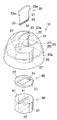
カーエアコン用熱交換器におけるアルミニウム(その合金を含む。)製熱交換チューブなどの金属製中空押出品を製造する際に用いられる押出成形用ダイスは、図18(a)に示すポートホールダイス、同図(b)に示すスパイダダイス、同図(c)に示すブリッジダイスと称されるものがある。 An extrusion die used for producing a metal hollow extruded product such as a heat exchange tube made of aluminum (including an alloy thereof) in a heat exchanger for a car air conditioner is a porthole die shown in FIG. There is a spider die shown in FIG. 2B and a bridge die shown in FIG.
これらの押出成形用ダイスは、オス型ダイス(1)とメス型ダイス(2)とが組み合わされて構成され、オス型ダイス(1)のマンドレル(1a)が、メス型ダイス(2)のダイス孔(2a)に対応して配置されて、マンドレル(1a)およびダイス孔(2a)によって環状の押出孔が形成される。そしてオス型ダイス(1)のビレット受圧面(金属材料受圧面1b)に押圧された金属ビレット(金属材料)が、材料導入部(1c)を通って両ダイス(1)(2)内に流入されて、上記押出孔を塑性変形しつつ通過することによって、押出孔の形状に対応した断面形状の押出材が成形加工されるよう構成されている。
These extrusion dies are configured by combining a male die (1) and a female die (2), and the mandrel (1a) of the male die (1) is the die of the female die (2). An annular extrusion hole is formed by the mandrel (1a) and the die hole (2a) arranged corresponding to the hole (2a). And the metal billet (metal material) pressed by the billet pressure receiving surface (metal material
このような押出成形用ダイスにおいては、オス型ダイス(1)のビレット受圧面(1b)に、金属ビレットの押圧による多大な応力が加わるため、その応力によって、ビレット受圧部周辺に亀裂が発生し易く、十分なダイス寿命を得ることが困難になるおそれがある。 In such an extrusion die, a great amount of stress is applied to the billet pressure-receiving surface (1b) of the male die (1) due to the pressure of the metal billet, which causes cracks around the billet pressure-receiving portion. It is easy to obtain a sufficient die life.
そこで従来においては、下記特許文献1,2に示す金属材料の押出成形用ダイスが提案されている。このダイスは、オス型ダイスのブリッジ部がメス型ダイスに取り付けられるブリッジダイスによって構成されるものであり、オス型ダイスのビレット受圧面をビレットの押出方向に対し反対側(後側)に突出する凸面形状に形成して、金属ビレットの押圧力を、凸面によって緩和して受け止めることにより、金属ビレットの押圧による悪影響を回避するようにしている。
而して、上記特許文献1,2に示す従来の押出成形用ダイスは、ビレット受圧面を凸面形状に形成しているため、金属ビレットに対する耐圧性など、オス型ダイスの強度をある程度向上させることができるものの、依然としてブリッジ部に強度的に不安を抱えている。このためブリッジ部の強度を十分に確保するには、オス型ダイスにおけるブリッジ部の肉厚などのサイズを不必要に大きくせざるを得ず、大型化および高重量化を来すばかりか、コストの増大も招くという問題が発生する。
Thus, since the conventional extrusion dies shown in
また押出成形用ダイスにおいて、特に複雑な形状に押出加工するような場合には、金属材料をオス型ダイスの材料導入部から押出孔にかけて安定状態にスムーズに導入する必要があるが、上記従来の押出成形用ダイスにおいては、オス型ダイスの材料導入部からオス型ダイスおよびメス型ダイス間に流入される金属材料がオス型ダイスのブリッジ部によって乱されて、金属材料のスムーズな導入が妨げられ、押出成形品の寸法精度が低下して、高い品質を得ることが困難になるおそれがあった。 In addition, in the extrusion die, particularly when extruding into a complicated shape, it is necessary to smoothly introduce a metal material into a stable state from the material introduction portion of the male die to the extrusion hole. In the extrusion die, the metal material flowing between the male die and the female die from the material introduction portion of the male die is disturbed by the bridge portion of the male die, preventing the smooth introduction of the metal material. In addition, the dimensional accuracy of the extrusion-molded product may be lowered, and it may be difficult to obtain high quality.
この発明の主たる目的は、上記従来技術の問題を解消し、十分な強度および耐久性を確保しつつ、コストの削減および小型軽量化を図ることができるとともに、高い品質の押出成形品を得ることができる金属材料の押出成形工具を提供することである。 The main object of the present invention is to eliminate the above-mentioned problems of the prior art and to achieve cost reduction and reduction in size and weight while ensuring sufficient strength and durability, and to obtain a high-quality extruded product. It is an object to provide an extrusion tool for a metal material.
この発明の他の目的は、上記目的を達成可能な熱交換チューブの押出成形工具、金属材料の押出成形方法、熱交換チューブの押出成形方法、金属材料の押出成形機および熱交換チューブの押出成形機を提供することである。 Other objects of the present invention are a heat exchange tube extrusion tool capable of achieving the above object, a metal material extrusion method, a heat exchange tube extrusion method, a metal material extrusion machine, and a heat exchange tube extrusion method. Is to provide a machine.
本発明は以下の手段を提供する。 The present invention provides the following means.
[1] ダイス保持孔を有するダイスホルダと、
ダイス保持孔内に挿入保持されたダイスと、
ダイスの前側に該ダイスの前端面に当接して配置されたバッカと、を備えた金属材料の押出成形工具であって、
ダイスは、
外表面を金属材料受圧面とする受圧部を有し、その受圧部の金属材料受圧面を金属材料の押出方向に対向させるように後方に向けて配置されるダイスケースと、
ダイスケースの内部に保持され、かつダイスケースの軸心に対応して配置されるマンドレルを有するオス型ダイスと、
ダイスケース内の前部に保持され、かつマンドレルとの間で押出孔を形成するダイス孔が設けられたメス型ダイスと、を備え、さらに、
受圧部における金属材料受圧面が後方に向けて突出する凸面形状に形成される一方、
受圧部の外周に、金属材料導入用のポート孔が設けられるとともに、そのポート孔の軸心が下流側に向かうに従ってダイスケースの軸心に近づくように、ダイスケースの軸心に対し傾斜するように配置され、且つ、
金属材料受圧面に押圧された金属材料が、ポート孔を通ってダイスケース内に導かれて、押出孔を通過するよう構成されており、
ダイスホルダのダイス保持孔の周面は、下流側に向かうに従って漸次拡径するテーパ面に形成されるとともに、
ダイスホルダのダイス保持孔の周面に当接する、ダイスのダイスケースの前部の外周面は、ダイス保持孔の周面に対応したテーパ面に形成されたことを特徴とする金属材料の押出成形工具。
[1] A die holder having a die holding hole;
A die inserted and held in the die holding hole;
A metal material extrusion tool comprising a backer disposed on the front side of the die in contact with the front end surface of the die,
Dice
A die case having a pressure receiving portion having an outer surface as a metal material pressure receiving surface, and disposed rearward so that the metal material pressure receiving surface of the pressure receiving portion faces the extrusion direction of the metal material;
A male die having a mandrel held inside the die case and arranged corresponding to the axis of the die case;
A female die that is held at the front part in the die case and provided with a die hole that forms an extrusion hole with the mandrel, and further,
While the metal material pressure receiving surface in the pressure receiving portion is formed in a convex shape protruding backward,
A port hole for introducing a metal material is provided on the outer periphery of the pressure receiving portion, and the port hole is inclined with respect to the axis of the die case so that the axis of the port hole approaches the axis of the die case as it goes downstream. And
The metal material pressed against the metal material pressure receiving surface is configured to be guided into the die case through the port hole and pass through the extrusion hole.
The peripheral surface of the die holding hole of the die holder is formed into a tapered surface that gradually increases in diameter toward the downstream side,
A metal material extrusion tool characterized in that the outer peripheral surface of the front portion of the die case of the die that is in contact with the peripheral surface of the die holding hole of the die holder is formed into a tapered surface corresponding to the peripheral surface of the die holding hole. .
[2] ダイスの前端面を含む前端部がダイスホルダの前端面よりも前方に突出している前項1記載の金属材料の押出成形工具。
[2] The metal material extrusion tool according to
[3] ダイスホルダの前端面に対するダイスの前端部の前方への突出量が0.3〜2mmの範囲に設定された請求項2に記載の金属材料の押出成形工具。
[3] The metal material extrusion tool according to
[4] ダイスホルダのダイス保持孔の周面のテーパ半角は3〜8°の範囲に設定された前項1〜3のいずれか1項に記載の金属材料の押出成形工具。
[4] The metal material extrusion tool according to any one of
[5] ダイスの金属材料受圧面が、球面の一部からなる凸球面によって構成された前項1〜4のいずれか1項に記載の金属材料の押出成形工具。
[5] The metal material extrusion tool according to any one of
[6] ダイスの金属材料受圧面が、1/6〜4/6球体の凸球面によって構成された前項1〜5のいずれか1項に記載の金属材料の押出成形工具。
[6] The metal material extrusion tool according to any one of
[7] ダイスのポート孔は、ダイスケースの軸心回りに周方向に等間隔おきに複数形成された前項1〜6のいずれか1項に記載の金属材料の押出成形工具。
[7] The metal material extrusion molding tool according to any one of the preceding
[8] ダイスのポート孔は、押出孔に向けて配置された前項1〜7のいずれか1項に記載の金属材料の押出成形工具。
[8] The metal material extrusion tool according to any one of
[9] ダイスは、
オス型ダイスのマンドレルと、メス型ダイスのダイス孔との間によって、高さ(厚さ)が幅に対し小さい偏平な環状の押出孔が形成されるとともに、
マンドレルにおけるダイス孔に対応する部分が、幅方向に併設された複数の通路成形用凸部を有する櫛歯状に形成されて、
金属材料が押出孔を通過することによって、複数の通路が幅方向に併設された多孔中空材が押出成形されるよう構成された前項1〜8のいずれか1項に記載の金属材料の押出成形工具。
[9] Dice is
Between the mandrel of the male die and the die hole of the female die, a flat annular extrusion hole whose height (thickness) is smaller than the width is formed,
The portion corresponding to the die hole in the mandrel is formed in a comb-teeth shape having a plurality of passage molding convex portions provided side by side in the width direction,
The extrusion molding of the metal material according to any one of the preceding
[10] 多孔中空材が、熱交換器の熱交換チューブとして用いられる前項9に記載の金属材料の押出成形工具。 [10] The metal material extrusion tool according to item 9, wherein the porous hollow member is used as a heat exchange tube of a heat exchanger.
[11] ダイスのオス型ダイスのマンドレルと、メス型ダイスのダイス孔との間によって、高さが幅に対し小さい偏平な環状の押出孔が形成され、
ポート孔が押出孔の高さ方向(厚さ方向)両側に対応する位置に配置された前項1〜10のいずれか1項に記載の金属材料の押出成形工具。
[11] A flat annular extrusion hole whose height is small with respect to the width is formed between the mandrel of the male die of the die and the die hole of the female die,
11. The metal material extrusion tool according to any one of the preceding
[12] ダイスのダイスケースは、その前部に受圧部と一体に環状ベース部が設けられた前項1〜11のいずれか1項に記載の金属材料の押出成形工具。
[12] The die molding tool for metal material according to any one of
[13] 金属材料が、アルミニウムまたはその合金によって構成された前項1〜12のいずれか1項に記載の金属材料の押出成形工具。
[13] The extrusion tool for a metal material according to any one of
[14] 前項1〜13のいずれか1項に記載の押出成形工具を用いて金属製押出成形品を成形することを特徴とする押出成形品の製造方法。
[14] A method for producing an extruded product, comprising molding a metal extruded product using the extrusion tool according to any one of
[15] 前項10に記載の押出成形工具を用いて金属製多孔中空材を成形することを特徴とする多孔中空材の製造方法。
[15] A method for producing a porous hollow material, wherein the metal porous hollow material is molded using the extrusion molding tool according to the
[16] 前項10に記載の押出成形工具を用いて熱交換器の金属製熱交換チューブを成形することを特徴とする熱交換チューブの製造方法。
[16] A method for producing a heat exchange tube, wherein the metal heat exchange tube of a heat exchanger is formed using the extrusion molding tool according to
[17] 前項1〜13のいずれか1項に記載の押出成形工具を用いて金属製押出成形品を成形することを特徴とする金属材料の押出成形方法。
[17] A method for extruding a metal material, comprising forming a metal extrudate using the extrusion tool according to any one of
[18] コンテナの前側に設置される押出成形工具として、前項1〜13のいずれか1項に記載の押出成形工具を備えたことを特徴とする金属材料の押出成形機。
[18] A metal material extrusion molding machine comprising the extrusion molding tool according to any one of
発明[1]の金属材料の押出成形工具によれば、ダイスのダイスケースの受圧部の金属材料受圧面を凸面形状に形成しているため、金属材料が受圧面に押圧された際に、金属材料の押圧力を凸面によって分散させて受け止めることができて、受圧面の各部分での法線方向の押圧力を低減することができる。このため金属材料の押圧力に対するダイスの強度を向上できて、十分な耐久性を得ることができる。すなわち、金属材料が凸面形状に形成された受圧面に押圧された場合、受圧面の各部位には受圧部の軸心に向かう方向の圧縮力が加わるため、押出成形時にダイスケースに生じる剪断力が低減される。その結果、このダイスケースにおいて最も剪断力が大きく生じる部位である、ダイスケースの中空部に露出した部位について、該部位に生じる剪断力を低減でき、もって金属材料の押圧力に対するダイスの強度を向上させることができる。 According to the metal material extrusion molding tool of the invention [1], since the metal material pressure receiving surface of the pressure receiving portion of the die case of the die is formed in a convex shape, the metal material is pressed when the metal material is pressed against the pressure receiving surface. The pressing force of the material can be dispersed and received by the convex surface, and the pressing force in the normal direction at each portion of the pressure receiving surface can be reduced. For this reason, the strength of the die against the pressing force of the metal material can be improved, and sufficient durability can be obtained. That is, when a metal material is pressed against a pressure-receiving surface formed in a convex shape, a compressive force in the direction toward the axis of the pressure-receiving portion is applied to each part of the pressure-receiving surface, so that a shear force generated in the die case during extrusion molding Is reduced. As a result, the shear force generated in the hollow part of the die case, which is the part where the most shear force is generated in this die case, can be reduced, thereby improving the strength of the die against the pressing force of the metal material. Can be made.
さらに、この押出成形工具においては、ダイスのオス型ダイスおよびメス型ダイスを覆うダイスケースの受圧部の外周に、材料流入用のポート孔が形成されており、受圧部の前端(下流側)壁部が周方向に連続して一体に形成されているため、この連続周壁部の存在によって、ダイスケース、ひいてはダイス全体の強度を一段と向上させることができる。このように本発明の押出成形工具のダイスは、従来のダイスにおけるブリッジ部などの強度的に弱い部分が存在せず、強度向上のために必要以上に肉厚などのサイズを大きく形成する必要もないため、小型軽量化を図ることができるとともに、コストも削減することができる。 Further, in this extrusion molding tool, a material inflow port hole is formed on the outer periphery of the pressure receiving portion of the die case that covers the male die and the female die of the die, and the front end (downstream side) wall of the pressure receiving portion Since the portions are continuously formed integrally in the circumferential direction, the presence of the continuous peripheral wall portion can further improve the strength of the die case and thus the entire die. As described above, the die of the extrusion tool of the present invention does not have a weak portion such as a bridge portion in the conventional die, and it is necessary to form a size such as a wall thickness larger than necessary for improving the strength. Therefore, the size and weight can be reduced and the cost can be reduced.
さらに、この押出成形工具においては、ダイスのポート孔を受圧部の外周に設けるとともに、そのポート孔の軸心を下流側に向かうに従ってダイスケースの軸心に近づくように、ダイスケースの軸心に対し傾斜するように配置しているため、ポート孔を流通する金属材料がダイスケース内の軸心、つまり押出孔にスムーズに導かれて、安定状態で押出加工することができ、高品質の押出成形品を得ることができる。 Further, in this extrusion molding tool, the port hole of the die is provided on the outer periphery of the pressure receiving portion, and the axial center of the die case is made closer to the axial center of the die case as it goes downstream. The metal material that circulates through the port hole is smoothly guided to the shaft center in the die case, that is, the extrusion hole, and can be extruded in a stable state. A molded product can be obtained.
さらに、この押出成形工具においては、ダイスホルダのダイス保持孔の周面が、下流側に向かうに従って漸次拡径するテーパ面に形成されるとともに、ダイスホルダのダイス保持孔の周面に当接した、ダイスのダイスケースの前部の外周面が、ダイス保持孔の周面に対応したテーパ面に形成されている。さらに、ダイスの前側に該ダイスの前端面に当接してバッカが配置されている。したがって、押出成形時にダイスホルダに加わる前方向の押圧力によってダイスの前端面がバッカに圧接されて、ダイスがダイス保持孔内において後方側(上流側)に押され、これにより、ダイス保持孔の周面からダイスのダイスケースの前部に縮径方向の圧縮力が加わるから、金属材料の押圧力に対するダイスの強度を更に向上できて、ダイスの寿命を更に延ばすことができる。 Furthermore, in this extrusion molding tool, the peripheral surface of the die holding hole of the die holder is formed into a tapered surface that gradually increases in diameter toward the downstream side, and is in contact with the peripheral surface of the die holding hole of the die holder. The outer peripheral surface of the front portion of the die case is formed into a tapered surface corresponding to the peripheral surface of the die holding hole. Further, a backer is disposed on the front side of the die in contact with the front end surface of the die. Therefore, the front end surface of the die is pressed against the backer by the forward pressing force applied to the die holder during extrusion molding, and the die is pushed rearward (upstream) in the die holding hole. Since a compressive force in the diameter reducing direction is applied from the surface to the front portion of the die case of the die, the strength of the die against the pressing force of the metal material can be further improved, and the life of the die can be further extended.
発明[2]の金属材料の押出成形工具によれば、ダイスの前端面を含む前端部がダイスホルダの前端面よりも前方に突出しているので、押出成形時にダイスホルダに加わる前方向の押圧力によってダイスの前端面がバッカに確実に圧接されて、ダイスがダイス保持孔内において後方側(上流側)に確実に押され、これにより、ダイス保持孔の周面からダイスのダイスケースの前部に縮径方向の圧縮力が確実に加わるから、金属材料の押圧力に対するダイスの強度を確実に向上できて、ダイスの寿命を確実に延ばすことができる。 According to the metal material extrusion tool of the invention [2], since the front end portion including the front end surface of the die protrudes forward from the front end surface of the die holder, the die is pressed by the forward pressing force applied to the die holder during extrusion molding. The front end surface of the die is securely pressed against the backer, and the die is surely pushed backward (upstream) in the die holding hole, so that the die is compressed from the peripheral surface of the die holding hole to the front of the die case of the die. Since the compressive force in the radial direction is reliably applied, the strength of the die against the pressing force of the metal material can be reliably improved, and the life of the die can be reliably extended.
発明[3]の金属材料の押出成形工具によれば、ダイスホルダの前端面に対するダイスの前端部の前方への突出量が所定の範囲に設定されているので、押出成形時にダイスの前端面がバッカに更に確実に圧接され、もって、金属材料の押圧力に対するダイスの強度を更に確実に向上できて、ダイスの寿命を更に確実に延ばすことができる。 According to the metal material extrusion tool of the invention [3], the forward protrusion amount of the front end portion of the die with respect to the front end surface of the die holder is set within a predetermined range. Therefore, the strength of the die against the pressing force of the metal material can be improved more reliably, and the life of the die can be further extended.
発明[4]の金属材料の押出成形工具によれば、ダイスホルダのダイス保持孔の周面のテーパ半角が所定の範囲に設定されているので、金属材料の押圧力に対するダイスの強度を確実に向上できて、ダイスの寿命を確実に延ばすことができる。 According to the metal material extrusion tool of the invention [4], since the taper half angle of the peripheral surface of the die holding hole of the die holder is set within a predetermined range, the strength of the die against the pressing force of the metal material is surely improved. This can surely extend the life of the die.
発明[5]の金属材料の押出成形工具によれば、ダイスの受圧部の金属材料受圧面を凸球面によって構成しているため、金属材料の受圧面への押圧力をバランス良く分散できて、金属材料の押圧力に対するダイスの強度を一層向上させることができる。すなわち、金属材料が凸球面によって構成された受圧面に押圧された場合、受圧面の各部位には受圧部の中心に向かう方向の圧縮力が加わるため、押出成形時にダイスケースに生じる剪断力が一層低減される。その結果、このダイスケースにおいて最も剪断力が大きく生じる部位である、ダイスケースの中空部に露出した部位について、該部位に生じる剪断力を一層低減でき、もって金属材料の押圧力に対するダイスの強度を一層向上させることができる。 According to the metal material extrusion molding tool of the invention [5], the metal material pressure receiving surface of the pressure receiving portion of the die is constituted by a convex spherical surface, so that the pressing force of the metal material to the pressure receiving surface can be distributed in a well-balanced manner. The strength of the die against the pressing force of the metal material can be further improved. That is, when a metal material is pressed against a pressure receiving surface constituted by a convex spherical surface, a compressive force in the direction toward the center of the pressure receiving portion is applied to each part of the pressure receiving surface, so that a shear force generated in the die case during extrusion molding is applied. It is further reduced. As a result, the shear force generated in the hollow part of the die case, which is the part where the shear force is generated most in this die case, can be further reduced, and the strength of the die against the pressing force of the metal material can be reduced. This can be further improved.
発明[6]の金属材料の押出成形工具によれば、ダイスの金属材料受圧面を、特定の凸球面によって構成しているため、金属材料の受圧面への押圧力をより確実にバランス良く分散できて、金属材料の押圧力に対するダイスの強度をより確実に向上させることができる。 According to the metal material extrusion tool of the invention [6], the metal material pressure-receiving surface of the die is constituted by a specific convex spherical surface, so that the pressing force of the metal material to the pressure-receiving surface is more reliably distributed in a balanced manner. Thus, the strength of the die against the pressing force of the metal material can be improved more reliably.
発明[7]の金属材料の押出成形工具によれば、ダイスのポート孔を周方向に複数形成しているため、金属材料をダイスケース内に周方向から均等に導入でき、押出孔へとスムーズに供給でき、より安定状態に押出加工することができる。 According to the metal material extrusion tool of the invention [7], since a plurality of die port holes are formed in the circumferential direction, the metal material can be uniformly introduced into the die case from the circumferential direction and smoothly into the extrusion holes. And can be extruded to a more stable state.
発明[8]の金属材料の押出成形工具によれば、ダイスのポート孔を押出孔に向けて配置しているため、ポート孔に流入された金属材料を、よりスムーズに押出孔へと供給することができる。 According to the metal material extrusion tool of the invention [8], since the port hole of the die is arranged toward the extrusion hole, the metal material flowing into the port hole is supplied to the extrusion hole more smoothly. be able to.
発明[9]の金属材料の押出成形工具によれば、幅方向に複数の通路が並列に配置される多孔中空材を確実に成形することができる。 According to the metal material extrusion molding tool of the invention [9], it is possible to reliably mold the porous hollow material in which a plurality of passages are arranged in parallel in the width direction.
発明[10]の金属材料の押出成形工具によれば、熱交換器用のチューブを確実に得ることができる。 According to the metal material extrusion tool of the invention [10], a tube for a heat exchanger can be obtained reliably.
発明[11]の金属材料の押出成形工具によれば、偏平形状の押出孔に、ポート孔から金属材料をより安定した状態で確実に供給することができる。 According to the metal material extrusion tool of the invention [11], the metal material can be reliably supplied to the flat shaped extrusion hole from the port hole in a more stable state.
発明[12]の金属材料の押出成形工具によれば、ダイスのダイスケースは、その前部に受圧部と一体に環状ベース部が設けられるため、その環状ベース部により補強されて、ダイスケース、ひいてはダイス全体の強度をより一層向上させることができる。 According to the metal material extrusion tool of the invention [12], since the die base of the die is provided with the annular base portion integrally with the pressure receiving portion at the front portion thereof, the die case is reinforced by the annular base portion, As a result, the strength of the entire die can be further improved.
発明[13]の金属材料の押出成形工具によれば、アルミニウムまたはアルミニウム合金製の押出成形品を製造することができる。 According to the extrusion tool of the metal material of the invention [13], an extruded product made of aluminum or an aluminum alloy can be produced.
発明[14]によれば、上記と同様の作用効果を奏する金属製押出成形品の製造方法を提供できる。 According to the invention [14], it is possible to provide a method for producing a metal extrusion-molded product having the same effects as described above.
発明[15]によれば、上記と同様の作用効果を奏する金属製多孔中空材の製造方法を提供できる。 According to invention [15], the manufacturing method of the metal porous hollow material which show | plays the effect similar to the above can be provided.
発明[16]によれば、上記と同様の作用効果を奏する金属製熱交換チューブの製造方法を提供できる。 According to invention [16], the manufacturing method of the metal heat exchange tube which has an effect similar to the above can be provided.
発明[17]によれば、上記と同様の作用効果を奏する金属材料の押出成形方法を提供できる。 According to the invention [17], it is possible to provide a method for extruding a metal material having the same effects as described above.
発明[18]によれば、上記と同様の作用効果を奏する押出成形機を提供できる。 According to the invention [18], it is possible to provide an extruder having the same effects as described above.
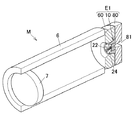
図1〜11は、この発明の第1実施形態に係る金属材料の押出成形工具(E1)を説明するための図である。この押出成形工具(E1)は、図14,15に示す多孔中空材(扁平多孔チューブ)(90)を押出成形するものである。 FIGS. 1-11 is a figure for demonstrating the extrusion tool (E1) of the metal material which concerns on 1st Embodiment of this invention. The extrusion tool (E1) is for extruding the porous hollow material (flat porous tube) (90) shown in FIGS.
中空材(90)は、金属製のもので、本実施形態において具体的には、アルミニウム(その合金を含む。)製熱交換チューブ(60)を構成している。 The hollow member (90) is made of metal, and specifically in the present embodiment, constitutes a heat exchange tube (60) made of aluminum (including its alloy).
この中空材(90)は、カーエアコン用のコンデンサなどの熱交換器に採用されるもので、偏平な形状を有している。中空材(90)の中空部(91)は、チューブ長さ方向に延び、かつ互いに平行に配置された複数の隔壁(92)によって、複数の熱交換用通路(93)に仕切られている。これらの通路(93)は、チューブ長さ方向に延び、かつ互いに平行に配置されている。 This hollow material (90) is employed in a heat exchanger such as a condenser for a car air conditioner, and has a flat shape. The hollow part (91) of the hollow member (90) is partitioned into a plurality of heat exchange passages (93) by a plurality of partition walls (92) extending in the tube length direction and arranged in parallel to each other. These passages (93) extend in the tube length direction and are arranged in parallel to each other.
なお、本実施形態においては、チューブ長さ方向に対し直交し、かつ通路(93)が並列される方向を「幅方向」とし、チューブ長さ方向に対し直交し、かつ幅方向に対し直交する方向を「高さ方向(厚さ方向)」として説明する。さらに本実施形態では、押出方向の「上流側」を「後側」とし、「下流側」を「前側」として説明する。 In the present embodiment, the direction perpendicular to the tube length direction and in which the passages (93) are arranged in parallel is referred to as the “width direction”, orthogonal to the tube length direction, and orthogonal to the width direction. The direction is described as “height direction (thickness direction)”. Further, in the present embodiment, the “upstream side” in the extrusion direction is described as “rear side”, and the “downstream side” is described as “front side”.
また本発明の押出成形工具(E1)を用いて押出成形される中空材(90)は、熱交換器の熱交換チューブとして用いられるものに限定されるものではなく、他の用途に用いられるものであっても良いし、その断面形状についても特に限定されるものではない。 Moreover, the hollow material (90) extruded using the extrusion tool (E1) of the present invention is not limited to one used as a heat exchange tube of a heat exchanger, but used for other purposes. The cross-sectional shape is not particularly limited.
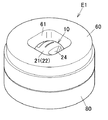
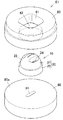
図1〜5に示すように、本第1実施形態の押出成形工具(E1)は、ダイス(10)と、ダイスホルダ(60)と、バッカ(80)とを基本的な構成要素として備えている。 As shown in FIGS. 1 to 5, the extrusion tool (E1) of the first embodiment includes a die (10), a die holder (60), and a backer (80) as basic components. .
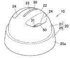
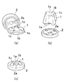
さらに、図6〜11に示すように、ダイス(10)は、ダイスケース(20)と、オス型ダイス(30)と、メス型ダイス(40)と、流動制御板(50)とを基本的な構成要素として備えている。 Further, as shown in FIGS. 6 to 11, the die (10) basically includes a die case (20), a male die (30), a female die (40), and a flow control plate (50). As a major component.
ダイス(10)の構成について以下に説明する。 The configuration of the die (10) will be described below.
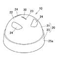
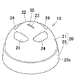
ダイス(10)のダイスケース(20)は、中空構造を有しており、金属材料としての金属ビレットの押出方向に対し、上流側(後側)に設けられる受圧部(21)と、下流側(前側)に設けられるベース部(25)とを有している。 The die case (20) of the die (10) has a hollow structure, and a pressure receiving portion (21) provided on the upstream side (rear side) with respect to the extrusion direction of the metal billet as the metal material, and the downstream side And a base portion (25) provided on the (front side).
受圧部(21)は、ドーム状に形成されており、金属ビレットの押出方向に対向する面(後面)が、金属材料受圧面としてのビレット受圧面(22)に形成されている。このビレット受圧面(22)は、押出方向に対向する方向(後方向)に突出する凸面形状として形成されており、具体的には半球面形状の凸球面(詳述すると凸真球面)として形成されている。 The pressure receiving portion (21) is formed in a dome shape, and a surface (rear surface) facing the extrusion direction of the metal billet is formed on a billet pressure receiving surface (22) as a metal material pressure receiving surface. The billet pressure-receiving surface (22) is formed as a convex shape that protrudes in the direction opposite to the extrusion direction (rearward direction), and specifically, a hemispherical convex spherical surface (detailed convex spherical surface). Has been.
受圧部(21)の周壁中央には、受圧部(21)の内部の中空部(ウェルドチャンバ12)に連通するオス型ダイス保持孔(23)が受圧部(21)の軸心(A1)に沿って設けられている。このオス型ダイス保持孔(23)の断面形状は、オス型ダイス(30)の断面形状に対応して、扁平な矩形状に形成されている。さらに、オス型ダイス保持孔(23)の後端側における幅方向両側部には、後述するオス型ダイス(30)を係合するために係合段部(23a)(23a)が設けられている。 At the center of the peripheral wall of the pressure receiving portion (21), a male die holding hole (23) communicating with the hollow portion (weld chamber 12) inside the pressure receiving portion (21) is formed in the shaft center (A1) of the pressure receiving portion (21). It is provided along. The cross-sectional shape of the male die holding hole (23) is formed in a flat rectangular shape corresponding to the cross-sectional shape of the male die (30). Furthermore, on both sides in the width direction on the rear end side of the male die holding hole (23), engagement step portions (23a) (23a) are provided to engage a male die (30) described later. Yes.
受圧部(21)の外周、詳述すると受圧部(21)の周壁における軸心(A1)を挟んだ両側には、一対のポート孔(24)(24)がそれぞれ形成されている。各ポート孔(24)の材料入口部の断面形状は、受圧部(21)の周方向に沿って延びる長孔形状を有しており、両ポート孔(24)(24)の材料入口部は互いに周方向に等間隔をおくように対向して配置されている。さらに、図9に示すように、各ポート孔(24)は下流側(前方)に向かうに従って受圧部(21)の軸心(A1)に近づくように、各ポート孔(24)の軸心(A2)が受圧部(21)の軸心(A1)に対し交差し、かつ傾斜して配置されている。このポート孔(24)の傾斜角度(θ2)などの詳細な構成については、後に詳述する。 A pair of port holes (24) and (24) are formed on both sides of the outer periphery of the pressure receiving portion (21), more specifically, on both sides of the axial center (A1) of the peripheral wall of the pressure receiving portion (21). The cross-sectional shape of the material inlet portion of each port hole (24) has a long hole shape extending along the circumferential direction of the pressure receiving portion (21), and the material inlet portions of both port holes (24) and (24) are They are arranged to face each other at regular intervals in the circumferential direction. Furthermore, as shown in FIG. 9, each port hole (24) has an axial center of each port hole (24) so as to approach the axial center (A 1) of the pressure receiving portion (21) toward the downstream side (forward). A2) intersects with and is inclined with respect to the axis (A1) of the pressure receiving portion (21). The detailed configuration such as the inclination angle (θ2) of the port hole (24) will be described in detail later.
なお本実施形態において、ダイスケース(20)の軸心と受圧部(21)の軸心とは一致するよう構成されている。 In the present embodiment, the axis of the die case (20) and the axis of the pressure receiving portion (21) are configured to coincide with each other.
ベース部(25)は、ダイスケース(20)の前部を構成するものであり、受圧部(21)と一体に形成されている。さらに、ベース部(25)はその外周面が受圧部(21)の他端側外周よりも外側に張り出すように形成されている。 The base portion (25) constitutes the front portion of the die case (20) and is formed integrally with the pressure receiving portion (21). Furthermore, the outer peripheral surface of the base part (25) is formed so as to protrude outward from the outer periphery on the other end side of the pressure receiving part (21).
ベース部(25)の内側には、内部のウェルドチャンバ(12)に連通し、かつメス型ダイス(40)の断面形状に対応する断面形状(即ち断面円形状)のメス型ダイス保持孔(26)が形成されている。そのため、ベース部(25)は円環状(詳述すると円筒状)に形成されている。また、このメス型ダイス保持孔(26)の前側の開口は、ベース部(25)の前端面の中央部、すなわちダイスケース(20)の前端面の中央部に形成されている。また、このメス型ダイス保持孔(26)の軸心は、ダイスケース(20)の軸心(A1)に一致するように構成されている。また、ベース部(25)の前端面、すなわちダイスケース(20)の前端面は押出方向に対し垂直に配置されている。 A female die holding hole (26) having a cross-sectional shape (that is, a circular cross-sectional shape) that communicates with the internal weld chamber (12) and corresponds to the cross-sectional shape of the female die (40) is formed inside the base portion (25). ) Is formed. Therefore, the base part (25) is formed in an annular shape (in detail, a cylindrical shape). The opening on the front side of the female die holding hole (26) is formed at the center of the front end surface of the base portion (25), that is, at the center of the front end surface of the die case (20). The axis of the female die holding hole (26) is configured to coincide with the axis (A1) of the die case (20). Further, the front end surface of the base portion (25), that is, the front end surface of the die case (20) is arranged perpendicular to the extrusion direction.
また、メス型ダイス保持孔(26)の周面における後端側には、図9などに示すように、後述するメス型ダイス(40)を流動制御板(50)を介して係合する係合段部(26a)が形成されている。さらに、図8に示すように、メス型ダイス保持孔(26)の周面における両側部には、ダイスケース(20)の軸心(A1)に対し平行な一対のキー溝(27)(27)が形成されている。 Further, on the rear end side of the peripheral surface of the female die holding hole (26), as shown in FIG. 9 and the like, a female die (40) described later is engaged through the flow control plate (50). A stepped portion (26a) is formed. Furthermore, as shown in FIG. 8, a pair of key grooves (27) (27) parallel to the axis (A1) of the die case (20) are formed on both sides of the peripheral surface of the female die holding hole (26). ) Is formed.
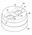
オス型ダイス(30)は、その前半の主要部がマンドレル(31)として構成されている。図9,10に示すように、マンドレル(31)は、ダイスケース(20)の軸心(A1)に対応して配置されるものである。また、マンドレル(31)の前端部は、中空材(90)の中空部(91)を成形するもので、中空材(90)の各通路(93)に対応した複数個の通路成形用凸部(33)を有している。これら複数の通路成形用凸部(33)は、マンドレル(31)の幅方向に所定間隔おきに並んで配置されている。さらにこれらの通路成形用凸部(33)の各間に設けられた隙間は、中空材(90)の隔壁(92)を形成する隔壁成形用溝(32)として構成されている。 In the male die (30), the main part of the first half is configured as a mandrel (31). As shown in FIGS. 9 and 10, the mandrel (31) is arranged corresponding to the axis (A1) of the die case (20). The front end portion of the mandrel (31) is for forming the hollow portion (91) of the hollow member (90), and a plurality of passage forming convex portions corresponding to the respective passages (93) of the hollow member (90). (33). The plurality of passage-forming convex portions (33) are arranged at predetermined intervals in the width direction of the mandrel (31). Furthermore, the gap provided between each of these passage-forming convex portions (33) is configured as a partition-forming groove (32) that forms a partition (92) of the hollow material (90).
オス型ダイス(30)の後端部における幅方向両側部には、ダイスケース(20)のオス型ダイス保持孔(23)の係合段部(23a)(23a)に対応して、係合凸部(33a)(33a)が側方突出状に一体に形成されている。 Engagement with the engagement step portions (23a) and (23a) of the male die holding hole (23) of the die case (20) is provided on both sides in the width direction at the rear end portion of the male die (30). The convex portions (33a) and (33a) are integrally formed in a laterally protruding shape.
そして、このオス型ダイス(30)が、オス型ダイス保持孔(23)に、そのビレット受圧面(22)側から挿入されて固定される。このとき、オス型ダイス(30)の係合凸部(33a)(33a)が、オス型ダイス保持孔(23)内の係合段部(23a)(23a)に係合されて、オス型ダイス(30)の位置決めが図られることにより、オス型ダイス(30)のマンドレル(31)が、オス型ダイス保持孔(23)からダイスケース(20)の内部に所定量突出した状態に保持される。 Then, the male die (30) is inserted into the male die holding hole (23) from the billet pressure receiving surface (22) side and fixed. At this time, the engagement protrusions (33a) and (33a) of the male die (30) are engaged with the engagement step portions (23a) and (23a) in the male die holding hole (23). By positioning the die (30), the mandrel (31) of the male die (30) is held in a state protruding a predetermined amount from the male die holding hole (23) into the die case (20). The
なお、オス型ダイス(30)の後端面(基端面)は、ダイスケース(20)の受圧部(21)のビレット受圧面(22)に倣う球面の一部に形成されており、オス型ダイス(30)の後端面とビレット受圧面(22)とにより協同で所望の円滑な凸球面が形成されるよう構成されている。 The rear end surface (base end surface) of the male die (30) is formed on a part of a spherical surface that follows the billet pressure receiving surface (22) of the pressure receiving portion (21) of the die case (20). (30) The rear end surface and the billet pressure-receiving surface (22) are configured to cooperatively form a desired smooth convex spherical surface.
メス型ダイス(40)は、円柱形状を有しており、図8に示すように外周面の両側部には、上記ダイスケース(20)におけるメス型ダイス保持孔(26)のキー溝(27)(27)に対応して、軸心と平行なキー突起(47)(47)が形成されている。 The female die (40) has a cylindrical shape, and as shown in FIG. 8, on both sides of the outer peripheral surface, the key groove (27) of the female die holding hole (26) in the die case (20). ) (27), key projections (47) (47) parallel to the axis are formed.
メス型ダイス(40)には、後端面側に開放し、かつオス型ダイス(30)のマンドレル(31)に対応して形成されたダイス孔(ベアリング孔41)と、ダイス孔(41)に連通し、かつ前端面側に開放するレリーフ孔(42)とが設けられている。 The female die (40) has a die hole (bearing hole 41) formed on the mandrel (31) of the male die (30) and opened to the rear end surface side, and a die hole (41). A relief hole (42) that communicates and opens to the front end face side is provided.
ダイス孔(41)は、その内周縁部に沿って内方突出部が設けられて、中空材(90)の外周部を成形できるよう構成されている。さらに、レリーフ孔(42)は、前端側(下流側)に向かうに従って次第に厚さ(高さ)が大きくなるように末広がりのテーパ状に形成されて、前側(下流側)に開放されている。 The die hole (41) is configured such that an inward protruding portion is provided along an inner peripheral edge portion thereof and an outer peripheral portion of the hollow material (90) can be formed. Furthermore, the relief hole (42) is formed in a taper shape which is widened toward the front end side (downstream side) so as to gradually increase in thickness (height), and is open to the front side (downstream side).
流動制御板(50)は、その外周形状が、上記ダイスケース(20)におけるメス型ダイス保持孔(26)の断面形状に対応して円形に形成されている。さらに流動制御板(50)の中央には、オス型ダイス(30)のマンドレル(31)およびメス型ダイス(40)のダイス孔(41)に対応して、中央貫通孔(51)が形成されている。 The flow control plate (50) has a circular outer shape corresponding to the cross-sectional shape of the female die holding hole (26) in the die case (20). Furthermore, a central through hole (51) is formed in the center of the flow control plate (50) corresponding to the mandrel (31) of the male die (30) and the die hole (41) of the female die (40). ing.
なお図8に示すように、流動制御板(50)における外周縁部の両側部には、上記ダイスケース(20)におけるメス型ダイス保持孔(26)のキー溝(27)(27)に対応して、キー突起(57)(57)が形成されている。 As shown in FIG. 8, on both sides of the outer peripheral edge of the flow control plate (50), it corresponds to the key grooves (27) (27) of the female die holding hole (26) in the die case (20). Thus, key protrusions (57) (57) are formed.
そして、上記メス型ダイス(40)が、ダイスケース(20)のメス型ダイス保持孔(26)に前側から流動制御板(50)を介して収容されて固定される。このとき、メス型ダイス(40)の一端面(後端面)外周が流動制御板(50)の外周縁部を介して、メス型ダイス保持孔(26)の係合段部(26a)に係合されることにより、メス型ダイス(40)および流動制御板(50)の軸心方向(押出方向)の位置決めが図られるとともに、メス型ダイス(40)のキー突起(47)(47)および流動制御板(50)のキー突起(57)(57)がメス型ダイス保持孔(26)のキー溝(27)(27)に係合されることにより、軸心回り方向の位置決めが図られる。 The female die (40) is housed and fixed in the female die holding hole (26) of the die case (20) from the front side via the flow control plate (50). At this time, the outer periphery of one end surface (rear end surface) of the female die (40) is engaged with the engaging step portion (26a) of the female die holding hole (26) via the outer peripheral edge portion of the flow control plate (50). As a result, positioning of the female die (40) and the flow control plate (50) in the axial direction (extrusion direction) is achieved, and the key protrusions (47) (47) and the female die (40) The key protrusions (57) and (57) of the flow control plate (50) are engaged with the key grooves (27) and (27) of the female die holding hole (26), thereby positioning in the direction around the axis. .
また、メス型ダイス(40)がダイスケース(20)のメス型ダイス保持孔(26)内に収容固定された状態において、メス型ダイス(40)の前端面は、ダイスケース(20)の前端面(詳述すると、受圧部(21)の前端面)と同一位置に配置されて、ダイスケース(20)の前端面と面一に連なっている。このように互いに面一に連なったメス型ダイス(40)の前端面とダイスケース(20)の前端面とにより、ダイス(10)の前端面(10a)が平坦状に形成されている。換言すると、ダイス(10)の前端面(10a)は、メス型ダイス(40)の前端面とダイスケース(20)の前端面とから形成されており、両方の前端面が互いに面一に連なっているため、ダイス(10)の前端面(10a)が平坦状に形成されている。 In the state where the female die (40) is housed and fixed in the female die holding hole (26) of the die case (20), the front end surface of the female die (40) is the front end of the die case (20). It arrange | positions in the same position as a surface (the front end surface of a pressure receiving part (21) if it explains in full detail), and continues to the front end surface of the die case (20). The front end surface (10a) of the die (10) is formed in a flat shape by the front end surface of the female die (40) and the front end surface of the die case (20) that are flush with each other. In other words, the front end surface (10a) of the die (10) is formed from the front end surface of the female die (40) and the front end surface of the die case (20), and both front end surfaces are flush with each other. Therefore, the front end face (10a) of the die (10) is formed flat.
なお本発明では、もしメス型ダイス(40)の前端面とダイスケース(20)の前端面とが互いに面一に連なっていない場合には、両方の前端面のうち最も前方に位置している面が、ダイス(10)の前端面(10a)に対応することとなる。 In the present invention, if the front end face of the female die (40) and the front end face of the die case (20) are not flush with each other, they are located at the forefront of both front end faces. The surface corresponds to the front end surface (10a) of the die (10).
以上のようにして、ダイス(10)は、メス型ダイス(40)をダイスケース(20)内の前部(即ちベース部(25)の内部)に前側から取り付けられるよう構成されている。 As described above, the die (10) is configured so that the female die (40) can be attached to the front portion in the die case (20) (that is, inside the base portion (25)) from the front side.
また、このダイス(10)において、オス型ダイス(30)のマンドレル(31)およびメス型ダイス(40)のダイス孔(41)は、流動制御板(50)の中央貫通孔(51)内に対応して配置される。このとき、図9〜11に示すように、オス型ダイス(30)のマンドレル(31)が、メス型ダイス(40)のダイス孔(41)の内側に配置されて、マンドレル(31)およびダイス孔(41)間で偏平環状の押出孔(11)が形成される。さらに、この押出孔(11)は、マンドレル(31)の複数の隔壁形成溝(32)が幅方向に並列に配置されて、成形される上記中空材(90)の断面形状に対応して形成される。 In this die (10), the mandrel (31) of the male die (30) and the die hole (41) of the female die (40) are located in the central through hole (51) of the flow control plate (50). Correspondingly arranged. At this time, as shown in FIGS. 9 to 11, the mandrel (31) of the male die (30) is disposed inside the die hole (41) of the female die (40), and the mandrel (31) and the die are arranged. A flat annular extrusion hole (11) is formed between the holes (41). Further, the extrusion hole (11) is formed corresponding to the cross-sectional shape of the hollow material (90) to be formed by arranging a plurality of partition forming grooves (32) of the mandrel (31) in parallel in the width direction. Is done.
ここで、本第1実施形態において、ダイスケース(20)のポート孔(24)の詳細な構成について説明する。まず、上下一対のポート孔(24)(24)は、ダイス(10)の押出孔(11)の高さ方向(厚さ方向)両側に対応する位置に配置されて、一対のポート孔(24)(24)の流出側端部(前端部)が、押出孔(11)に対応して配置されている。 Here, in the first embodiment, a detailed configuration of the port hole (24) of the die case (20) will be described. First, the pair of upper and lower port holes (24) and (24) are arranged at positions corresponding to both sides in the height direction (thickness direction) of the extrusion hole (11) of the die (10), and the pair of port holes (24 ) (24), the outflow side end (front end) is arranged corresponding to the extrusion hole (11).
また既述したようにポート孔(24)(24)は、その軸心(A2)がダイスケース(20)の軸心(A1)に対し傾斜するように設定されている。図9に示すように、本実施形態において、ダイスケース(20)の軸心(A1)に対するポート孔(24)の軸心(A2)の傾斜角度(θ2)は、3〜35°に設定するのが良く、好ましくは5〜30°、特に好ましくは5〜25°に設定するのが良い。すなわち、この傾斜角度(θ2)を上記特定の範囲内に設定する場合には、ビレットがポート孔(24)(24)およびウェルドチャンバ(12)を安定した状態で流通して、さらにビレットが押出孔(11)をその全周にわたってバランス良くスムーズに通過して、寸法精度に優れた高品質の押出成形品(押出加工品)(90)を形成することができる。換言すれば、上記傾斜角度(θ2)が小さ過ぎる場合には、ポート孔(24)(24)およびウェルドチャンバ(12)を流通したビレットが、押出孔(11)にスムーズに導入されず、高品質の押出成形品(90)を安定して得ることが困難になるおそれがある。逆に傾斜角度(θ2)が大き過ぎる場合には、材料押出方向に対し、ポート孔(24)の材料流通方向が大きく傾斜するため、ビレットの押出荷重が大きくなるので、好ましくない。ただし本発明では、ポート孔(24)の軸心(A2)の傾斜角度(θ2)は上記の範囲内であることに限定されるものではない。 As described above, the port holes (24) and (24) are set such that the axis (A2) thereof is inclined with respect to the axis (A1) of the die case (20). As shown in FIG. 9, in this embodiment, the inclination angle (θ2) of the axis (A2) of the port hole (24) with respect to the axis (A1) of the die case (20) is set to 3 to 35 °. It is preferable to set it at 5 to 30 °, particularly preferably 5 to 25 °. That is, when this inclination angle (θ2) is set within the specific range, the billet flows in a stable state through the port holes (24) and (24) and the weld chamber (12), and the billet is further extruded. The hole (11) can be smoothly passed through the entire circumference in a well-balanced manner to form a high-quality extruded product (extruded product) (90) having excellent dimensional accuracy. In other words, when the inclination angle (θ2) is too small, the billet that has circulated through the port holes (24), (24) and the weld chamber (12) is not smoothly introduced into the extrusion hole (11), It may be difficult to stably obtain a quality extruded product (90). On the contrary, when the inclination angle (θ2) is too large, the material flow direction of the port hole (24) is greatly inclined with respect to the material extrusion direction, which is not preferable because the extrusion load of the billet becomes large. However, in the present invention, the inclination angle (θ2) of the axis (A2) of the port hole (24) is not limited to the above range.
また本実施形態において、ダイスケース(20)におけるビレット受圧面(22)を、1/6〜4/6球体の凸球面によって構成するのが良い。ビレット受圧面(22)を上記特定の凸球面によって構成する場合には、ビレット受圧面(22)によって金属ビレットの押圧力をより確実にバランス良く分散して受け止めることができ、十分な強度をより確実に確保できて、ダイス寿命をより確実に向上させることができる。すなわち、ビレットが特定の凸球面によって構成された受圧面(22)に押圧された場合、受圧面(22)の各部位には受圧部(21)の中心に向かう方向の圧縮力がより確実に加わるため、押出成形時にダイスケース(20)に生じる剪断力がより確実に低減される。その結果、このダイスケース(20)において最も剪断力が大きく生じる部位である、ダイスケース(20)の中空部に露出した部位について、該部位に生じる剪断力をより確実に低減でき、もってビレットの押圧力に対するダイス(10)の強度をより確実に向上させることができる。そればかりかダイス形状の簡素化、ダイス(10)の小型軽量化およびコストの削減を図ることができる。換言すれば、ビレット受圧面(22)を、1/6球体に満たない球体、たとえば1/8球体の凸球面によって構成した場合には、ビレットの押圧力に対し十分な強度を得ることができず、亀裂の発生によるダイス寿命の低下を来すおそれがある。逆にビレット受圧面(22)を、4/6球体を超える球体、たとえば5/6球体の凸球面によって構成した場合には、ビレット受圧面(22)の形状の複雑化によるコストの増大を来すおそれがある。 Moreover, in this embodiment, it is good to comprise the billet pressure-receiving surface (22) in the die case (20) with the convex spherical surface of 1/6-4/6 sphere. When the billet pressure receiving surface (22) is constituted by the above-mentioned specific convex spherical surface, the billet pressure receiving surface (22) can receive the pressing force of the metal billet in a more balanced manner and with sufficient strength. It can be ensured and the die life can be improved more reliably. That is, when the billet is pressed against the pressure receiving surface (22) configured by a specific convex spherical surface, the compressive force in the direction toward the center of the pressure receiving portion (21) is more reliably applied to each part of the pressure receiving surface (22). Therefore, the shearing force generated in the die case (20) during extrusion molding is more reliably reduced. As a result, the shearing force generated in the hollow portion of the die case (20), which is the part where the shearing force is most generated in the die case (20), can be more reliably reduced, and the billet The strength of the die (10) against the pressing force can be improved more reliably. In addition, the die shape can be simplified, the die (10) can be reduced in size and weight, and the cost can be reduced. In other words, when the billet pressure-receiving surface (22) is constituted by a sphere less than 1/6 sphere, for example, a convex sphere of 1/8 sphere, sufficient strength against the pressing force of the billet can be obtained. Therefore, the die life may be shortened due to the occurrence of cracks. Conversely, when the billet pressure receiving surface (22) is constituted by a sphere exceeding 4/6 spheres, for example, a convex spherical surface of a 5/6 sphere, the cost of the billet pressure receiving surface (22) increases due to the complicated shape. There is a risk.
ここで本実施形態においてたとえば、1/8球体、1/6球体、4/6球体などの割合付きの球体は、完全球体を軸心に対し直交する方向に切断して切り取った際の部分球体によって構成されるものである。すなわち本実施形態において「n/m球体(ただしm、nは自然数、n<mである)」とは、完全球体の軸心長さ(直径)を「1」として、完全球体の端縁からの軸心(直径)方向の長さがn/mの位置で、その完全球体を、軸心に対し直交する方向に切り取った際の部分球体によって構成されるものである。 Here, in this embodiment, for example, a sphere with a ratio such as 1/8 sphere, 1/6 sphere, 4/6 sphere, etc. is a partial sphere obtained by cutting a complete sphere in a direction perpendicular to the axis. It is comprised by. That is, in this embodiment, “n / m sphere (where m and n are natural numbers, n <m)” means that the axial length (diameter) of the complete sphere is “1” and the edge of the complete sphere is The complete sphere is constituted by a partial sphere when the length in the axial center (diameter) direction is n / m and cut in a direction orthogonal to the axial center.
なお本実施形態において、図9に示すように、ポート孔(24)の内周面のうち内側面(24a)および外側面(24b)は、互いにほぼ平行に配置されるとともに、ポート孔(24)の軸心(A2)に対しほぼ平行に配置されている。さらにポート孔内周面の内側面(24a)および外側面(24b)は、ダイスケース(20)の軸心(A1)に対し傾斜する傾斜面(テーパ面)としてそれぞれ構成されている。 In the present embodiment, as shown in FIG. 9, the inner side surface (24a) and the outer side surface (24b) of the inner peripheral surface of the port hole (24) are arranged substantially parallel to each other, and the port hole (24 ) Is arranged substantially parallel to the axis (A2). Furthermore, the inner side surface (24a) and the outer side surface (24b) of the inner peripheral surface of the port hole are respectively configured as inclined surfaces (tapered surfaces) that are inclined with respect to the axis (A1) of the die case (20).
次に、ダイスホルダ(60)の構成について以下に説明する。 Next, the configuration of the die holder (60) will be described below.
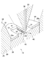
図1〜5に示すように、ダイスホルダ(60)(ダイス設置プレート)は、板状(詳述すると円板状)のものであり、その中央部にダイスホルダ(60)の厚さ方向に貫通した断面略四角形状の貫通孔(61)(ダイス設置孔)が設けられ、これによりダイスホルダ(60)が環状(リング状)に形成されている。また、図3に示すように、ダイスホルダ(60)の前端面(60a)及び後端面はそれぞれ平坦状に形成されている。 As shown in FIGS. 1 to 5, the die holder (60) (die installation plate) is plate-shaped (specifically, disc-shaped), and penetrates in the thickness direction of the die holder (60) at the center thereof. A through-hole (61) (die installation hole) having a substantially square cross section is provided, whereby the die holder (60) is formed in an annular shape (ring shape). Moreover, as shown in FIG. 3, the front end surface (60a) and the rear end surface of the die holder (60) are each formed in a flat shape.
さらに、図3〜5に示すように、ダイスホルダ(60)の貫通孔(61)の前部(即ち下流側の部分)は、ダイス(10)を保持するダイス保持孔(62)を構成している。このダイス保持孔(62)の断面形状は、ダイス(10)のダイスケース(20)の前部(25)(すなわちベース部(25))の断面形状に対応した形状であり、すなわち円形状である。さらに、ダイス保持孔(62)の後端側の口径は、貫通孔(61)の口径よりも小さく設定されており、これにより、ダイス設置孔(61)の周面とダイス保持孔(62)の周面(62a)との間の境界部分には段部が形成されている。 Furthermore, as shown to FIGS. 3-5, the front part (namely, downstream part) of the through-hole (61) of a die holder (60) comprises the die holding hole (62) holding a die (10). Yes. The cross-sectional shape of the die holding hole (62) is a shape corresponding to the cross-sectional shape of the front portion (25) (that is, the base portion (25)) of the die case (20) of the die (10). is there. Further, the diameter of the rear end side of the die holding hole (62) is set to be smaller than the diameter of the through hole (61), thereby the peripheral surface of the die installation hole (61) and the die holding hole (62). A step portion is formed at a boundary portion between the peripheral surface (62a) and the peripheral surface.
さらに、ダイス保持孔(62)の周面(62a)は、下流側に向かうに従って漸次拡径するテーパ面に形成されている。そして、このダイス保持孔(62)内に前方側からダイス(10)が密に挿入されて保持されている。 Furthermore, the peripheral surface (62a) of the die holding hole (62) is formed as a tapered surface that gradually increases in diameter toward the downstream side. The dice (10) is tightly inserted and held in the dice holding hole (62) from the front side.
一方、ダイス(10)のダイスケース(20)の前部の外周面、即ちベース部(25)の外周面(25a)は、ダイス保持孔(62)内にダイス(10)が挿入保持された状態のもとでダイス保持孔(62)の周面(62a)に面接触状態に当接している面であり、この外周面(25a)はダイス保持孔(62)の周面(62a)に対応したテーパ面に形成されている。 On the other hand, on the outer peripheral surface of the front portion of the die case (20) of the die (10), that is, the outer peripheral surface (25a) of the base portion (25), the die (10) is inserted and held in the die holding hole (62). This surface is in contact with the peripheral surface (62a) of the die holding hole (62) in a surface contact state under the state, and this outer peripheral surface (25a) is in contact with the peripheral surface (62a) of the die holding hole (62). A corresponding tapered surface is formed.
図5に示すように、ダイス保持孔(62)の周面(62a)が押出方向に対してなす角度、すなわち周面(62a)のテーパ半角(θ1)は、3〜8°(特に望ましくは4〜6°)の範囲に設定されるのが良い。こうすることにより、ビレットの押圧力に対するダイス(10)の強度を確実に向上させることができる。そのため、押出成形時に発生することのあるダイス(10)のダイスケース(20)の永久変形(塑性変形)およびメス型ダイス(40)の亀裂などを確実に防止することができるし、更にオス型ダイス(30)の摩耗を低減することができ、もってダイス(10)の寿命を確実に延ばすことができる。 As shown in FIG. 5, the angle formed by the peripheral surface (62a) of the die holding hole (62) with respect to the extrusion direction, that is, the taper half angle (θ1) of the peripheral surface (62a) is 3 to 8 ° (particularly desirably It is good to set it in the range of 4-6 degrees. By carrying out like this, the intensity | strength of the dice | dies (10) with respect to the pressing force of a billet can be improved reliably. Therefore, permanent deformation (plastic deformation) of the die case (20) of the die (10) and cracking of the female die (40), which may occur during extrusion molding, can be surely prevented. The wear of the die (30) can be reduced, and the life of the die (10) can be reliably extended.
本実施形態では、ダイス(10)のダイスケース(20)のベース部(25)の外周面(25a)のテーパ半角は、ダイス保持孔(62)の周面(62a)のテーパ半角(θ1)と等しく設定されている。 In this embodiment, the taper half angle of the outer peripheral surface (25a) of the base part (25) of the die case (20) of the die (10) is the taper half angle (θ1) of the peripheral surface (62a) of the die holding hole (62). Is set equal to
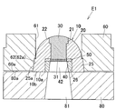
さらに、図5に示すように、ダイスホルダ(60)のダイス保持孔(62)内にダイス(10)が挿入保持された状態において、ダイス(10)の前端面(10a)を含む前端部(10b)(詳述すると、ダイス(10)のダイスケース(20)の前端面とメス型ダイス(40)の前端面とを含む前端部)は、ダイスホルダ(60)の前端面(60a)よりも前方に突出している。ダイスホルダ(60)の前端面(60a)に対するダイス(10)の前端部(10b)の前方への突出量(t)は0.3〜2mm(特に望ましくは0.4〜1.0mm)の範囲に設定されるのが良い。こうすることにより、押出成形時にダイス(10)の前端面(10a)がバッカ(80)に確実に圧接されて、ダイス(10)がダイス保持孔(62)内において後方(上流側)に確実に押される。これにより、ダイス保持孔(62)の周面(62a)からダイス(10)のダイスケース(20)の前部(すなわちベース部(25))に縮径方向の圧縮力が加わるから、ビレットの押圧力に対するダイス(10)の強度を更に向上させることができる。そのため、押出成形時に発生することのあるダイス(10)のダイスケース(20)の永久変形(塑性変形)およびメス型ダイス(40)の亀裂などを確実に防止することができるし、更にオス型ダイス(30)の摩耗を低減することができ、もってダイス(10)の寿命を確実に延ばすことができる。 Furthermore, as shown in FIG. 5, in a state where the die (10) is inserted and held in the die holding hole (62) of the die holder (60), the front end portion (10b) including the front end face (10a) of the die (10) (In detail, the front end portion including the front end surface of the die case (20) of the die (10) and the front end surface of the female die (40)) is more forward than the front end surface (60a) of the die holder (60). Protruding. The forward protrusion amount (t) of the front end portion (10b) of the die (10) with respect to the front end surface (60a) of the die holder (60) is in the range of 0.3 to 2 mm (particularly desirably 0.4 to 1.0 mm). It is good to be set to. By doing so, the front end surface (10a) of the die (10) is securely pressed against the backer (80) during extrusion molding, and the die (10) is reliably rearward (upstream) in the die holding hole (62). Pressed. Thereby, a compressive force in the diameter reducing direction is applied from the peripheral surface (62a) of the die holding hole (62) to the front portion (that is, the base portion (25)) of the die case (20) of the die (10). The strength of the die (10) against the pressing force can be further improved. Therefore, permanent deformation (plastic deformation) of the die case (20) of the die (10) and cracking of the female die (40), which may occur during extrusion molding, can be surely prevented. The wear of the die (30) can be reduced, and the life of the die (10) can be reliably extended.
次に、バッカ(80)の構成について以下に説明する。 Next, the configuration of the backer (80) will be described below.
図1〜5に示すように、バッカ(80)は、ダイス(10)およびダイスホルダ(60)の前側に固定状態に配置される板状のものである。バッカ(80)の前端面および後端面(80a)はそれぞれ平坦状に形成されている。そして、このバッカ(80)は、その後端面(80a)がダイス(10)の前端面(10a)に面接触状態に当接し且つダイスホルダ(60)の前端面(60a)には当接しないで配置されている。したがって、バッカ(80)とダイスホルダ(60)との間には僅かに隙間が生じている。 As shown in FIGS. 1-5, the backer (80) is a plate-like thing arrange | positioned in the fixed state on the front side of the dice (10) and the dice holder (60). The front end surface and the rear end surface (80a) of the backer (80) are each formed in a flat shape. The backer (80) is disposed such that the rear end surface (80a) thereof is in contact with the front end surface (10a) of the die (10) in a surface contact state and is not in contact with the front end surface (60a) of the die holder (60). Has been. Therefore, there is a slight gap between the backer (80) and the die holder (60).
バッカ(80)の中央部には、メス型ダイス(40)のレリーフ孔(42)と連通する貫通孔(81)がバッカ(80)の厚さ方向(すなわち押出方向)に貫通して設けられている。押出成形時には中空材(90)はレリーフ孔(42)内とこの貫通孔(81)内とを順次通過して前方へ移動される。 A through hole (81) communicating with the relief hole (42) of the female die (40) is provided in the center of the backer (80) so as to penetrate in the thickness direction of the backer (80) (that is, the extrusion direction). ing. At the time of extrusion molding, the hollow member (90) sequentially moves through the relief hole (42) and the through hole (81) and is moved forward.
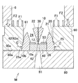
以上の構成の押出成形工具(E1)は、図12,13に示すように押出成形機(M)にセットされる。すなわち、押出成形工具(E1)のダイス(10)とダイスホルダ(60)とは、ダイス(10)がダイスホルダ(60)のダイス保持孔(62)内に挿入保持された状態で、押出成形機(M)のコンテナ(6)の前側に設置される。さらに、バッカ(80)がダイス(10)およびダイスホルダ(60)の前側にダイス(10)の前端面(10a)に圧接して固定状態に配置される。さらに、ビレットがダイスホルダ(60)とコンテナ(6)との間の隙間から漏出するのを防止するため、コンテナ(6)の前端面がダイスホルダ(60)に押し付けられる。 The extrusion tool (E1) having the above configuration is set in the extrusion machine (M) as shown in FIGS. That is, the die (10) and the die holder (60) of the extrusion molding tool (E1) are formed in the state where the die (10) is inserted and held in the die holding hole (62) of the die holder (60). It is installed on the front side of the container (6) of M). Further, the backer (80) is disposed in a fixed state in pressure contact with the front end face (10a) of the die (10) on the front side of the die (10) and the die holder (60). Further, the front end surface of the container (6) is pressed against the die holder (60) in order to prevent the billet from leaking from the gap between the die holder (60) and the container (6).
そして、この状態で、コンテナ(6)内に挿入されたアルミニウムビレットなどの金属ビレットを、ダミーブロック(7)を介して図12の右方向(押出方向)にステム(図示せず)で押し込む。これによりビレットは、ダイスホルダ(60)の貫通孔(61)内に導入され、さらにそのビレットがダイス(10)におけるダイスケース(20)のビレット受圧面(22)に押し付けられて塑性変形する。こうしてビレットが塑性変形しつつ、一対のポート孔(24)(24)を流通してダイスケース(20)のウェルドチャンバ(12)に導入され、さらに、押出孔(11)内を通って前方へ押し出されることにより、ビレットが押出孔(11)の開口形状に対応した断面形状に成形されて、押出成形品として中空材(90)が製造される。そして、この中空材(90)はレリーフ孔(42)内とバッカ(80)の貫通孔(81)内とを順次通過して前方へ移動される。 In this state, a metal billet such as an aluminum billet inserted into the container (6) is pushed into the right direction (extrusion direction) of FIG. 12 with a stem (not shown) via the dummy block (7). Thereby, the billet is introduced into the through hole (61) of the die holder (60), and the billet is pressed against the billet pressure receiving surface (22) of the die case (20) in the die (10) to be plastically deformed. In this way, the billet is plastically deformed, flows through the pair of port holes (24) and (24), is introduced into the weld chamber (12) of the die case (20), and further forwards through the extrusion hole (11). By being extruded, the billet is formed into a cross-sectional shape corresponding to the opening shape of the extrusion hole (11), and the hollow material (90) is manufactured as an extruded product. And this hollow material (90) passes the inside of a relief hole (42) and the inside of the through-hole (81) of a backer (80) sequentially, and is moved ahead.
而して、本第1実施形態の押出成形工具(E1)によれば、ダイス(10)のダイスケース(20)の受圧部(21)のビレット受圧面(22)を凸面形状に形成しているため、ビレットが受圧面(22)に押圧された際に、ビレットの押圧力を凸面によって分散させて受け止めることができて、受圧面(22)の各部分での法線方向の押圧力を低減することができる。このためビレットの押圧力に対するダイス(10)の強度を向上できる。すなわち、ビレットが凸面形状に形成された受圧面(22)に押圧された場合、受圧面(22)の各部位には受圧部(21)の軸心(A1)に向かう方向の圧縮力が加わるため、押出成形時にダイスケース(20)に生じる剪断力が低減される。その結果、このダイスケース(20)において最も剪断力が大きく生じる部位である、ダイスケース(20)の中空部に露出した部位について、該部位に生じる剪断力を低減でき、もってビレットの押圧力に対するダイス(10)の強度を向上させることができる。 Thus, according to the extrusion tool (E1) of the first embodiment, the billet pressure receiving surface (22) of the pressure receiving portion (21) of the die case (20) of the die (10) is formed in a convex shape. Therefore, when the billet is pressed against the pressure receiving surface (22), the pressing force of the billet can be dispersed and received by the convex surface, and the normal direction pressing force at each part of the pressure receiving surface (22) can be obtained. Can be reduced. For this reason, the intensity | strength of the dice | dies (10) with respect to the pressing force of a billet can be improved. That is, when the billet is pressed against the pressure receiving surface (22) formed in a convex shape, a compressive force in a direction toward the axis (A1) of the pressure receiving portion (21) is applied to each part of the pressure receiving surface (22). Therefore, the shear force generated in the die case (20) during extrusion molding is reduced. As a result, the shearing force generated in the hollow part of the die case (20), which is the part where the shearing force is generated most in the die case (20), can be reduced, so that the pressing force of the billet can be reduced. The strength of the die (10) can be improved.
しかも、この押出成形工具(E1)によれば、ダイス(10)の受圧部(21)のビレット受圧面(22)を凸球面によって構成しているため、ビレットの受圧面(22)への押圧力をバランス良く分散できて、ビレットの押圧力に対するダイス(10)の強度を一層向上させることができ、もって十分な耐久性を得ることができる。すなわち、ビレットが凸球面によって構成された受圧面(22)に押圧された場合、受圧面(22)の各部位には受圧部(21)の中心に向かう方向の圧縮力が加わるため、押出成形時にダイスケース(20)に生じる剪断力が一層低減される。その結果、このダイスケース(20)において最も剪断力が大きく生じる部位である、ダイスケース(20)の中空部に露出した部位について、該部位に生じる剪断力を一層低減でき、もってビレットの押圧力に対するダイス(10)の強度を一層向上させることができる。 Moreover, according to the extrusion tool (E1), the billet pressure receiving surface (22) of the pressure receiving portion (21) of the die (10) is constituted by a convex spherical surface, so that the billet is pressed against the pressure receiving surface (22). The pressure can be distributed in a well-balanced manner, and the strength of the die (10) against the pressing force of the billet can be further improved, so that sufficient durability can be obtained. That is, when the billet is pressed against the pressure receiving surface (22) constituted by the convex spherical surface, a compression force in the direction toward the center of the pressure receiving portion (21) is applied to each part of the pressure receiving surface (22). Sometimes the shear force generated in the die case (20) is further reduced. As a result, with respect to the portion exposed to the hollow portion of the die case (20), which is the portion where the largest shearing force is generated in the die case (20), the shearing force generated in the portion can be further reduced, and the pressing force of the billet It is possible to further improve the strength of the die (10).
さらに、本第1実施形態の押出成形工具(E1)によれば、ダイス(10)のオス型ダイス(30)およびメス型ダイス(40)を覆うダイスケース(20)の受圧部(21)の外周に、材料流入用のポート孔(24)を形成するものであり、受圧部(21)の前端壁部とベース部(25)の壁部とが共に周方向に連続して一体に形成されるため、この連続周壁部の存在によって、ダイスケース(20)、ひいてはダイス全体の強度を一段と向上させることができる。従って、従来のダイスにおけるブリッジ部などの強度的に弱い部分が存在せず、強度向上のために必要以上に肉厚などのサイズを大きく形成する必要もないため、小型軽量化を図ることができるとともに、コストも削減することができる。 Furthermore, according to the extrusion tool (E1) of the first embodiment, the pressure receiving portion (21) of the die case (20) covering the male die (30) and the female die (40) of the die (10). A port hole (24) for material inflow is formed on the outer periphery, and the front end wall portion of the pressure receiving portion (21) and the wall portion of the base portion (25) are both integrally formed continuously in the circumferential direction. Therefore, the presence of the continuous peripheral wall portion can further improve the strength of the die case (20), and thus the entire die. Accordingly, there is no weak portion such as a bridge portion in the conventional die, and it is not necessary to form a size such as a wall thickness larger than necessary for improving the strength, so that the size and weight can be reduced. At the same time, the cost can be reduced.
また、本第1実施形態の押出成型工具(E1)においては、ダイス(10)の受圧部(21)の軸心(A1)から逸脱した位置、つまり受圧部(21)の外周に、ポート孔(24)(24)を形成するとともに、そのポート孔(24)(24)の軸心(A2)を下流側に向かうに従ってダイスケース(20)の軸心に漸次近づくように、ダイスケース(20)の軸心(A1)に対し傾斜させているため、ポート孔(24)(24)を流通するビレットは、ダイスケース(20)の軸心(A1)、つまり押出孔(11)にスムーズに導かれていき、安定状態に押出加工することができる。さらに本実施形態においては、ポート孔(24)(24)の下流側端部(出口)を押出孔(11)に向けて配置しているため、ビレットを一層スムーズに押出孔(11)に導くことができる。 In the extrusion tool (E1) of the first embodiment, a port hole is formed at a position deviating from the axis (A1) of the pressure receiving portion (21) of the die (10), that is, at the outer periphery of the pressure receiving portion (21). (24) The die case (20) is formed so that (24) is formed and the axis (A2) of the port hole (24) (24) gradually approaches the axis of the die case (20) toward the downstream side. The billet that circulates through the port holes (24) and (24) smoothly flows into the axis (A1) of the die case (20), that is, the extrusion hole (11). It is guided and can be extruded into a stable state. Furthermore, in this embodiment, since the downstream end part (exit) of the port holes (24) and (24) is arranged toward the extrusion hole (11), the billet is more smoothly guided to the extrusion hole (11). be able to.
さらに、本第1実施形態の押出成形工具(E1)においては、ダイスホルダ(60)のダイス保持孔(62)の周面(62a)が、下流側に向かうに従って漸次拡径するテーパ面に形成されるとともに、ダイスホルダ(60)のダイス保持孔(62)の周面(62a)に当接した、ダイス(10)のダイスケース(20)の前部(すなわちベース部(25))の外周面(25a)が、ダイス保持孔(62)の周面(62a)に対応したテーパ面に形成されている。さらに、ダイス(10)の前側に該ダイス(10)の前端面(10a)に当接してバッカ(80)が配置されている。したがって、図13に示すように、押出成形時にダイスホルダ(60)に加わるビレットの前方向の押圧力(F1)と、更にコンテナ(6)からダイスホルダ(60)に加わるコンテナ(6)の前方向の押付け力(F2)とによって、ダイス(10)の前端面(10a)がバッカ(80)に圧接されて、ダイス(10)がダイス保持孔(62)内において後方側に押され、これにより、ダイス保持孔(62)の周面(62a)からダイス(10)のダイスケース(20)の前部(すなわちベース部(25))に縮径方向の圧縮力(C)が加わるから、ビレットの押圧力に対するダイス(10)の強度を更に向上できて、ダイス(10)の寿命を更に延ばすことができる。 Further, in the extrusion tool (E1) of the first embodiment, the peripheral surface (62a) of the die holding hole (62) of the die holder (60) is formed into a tapered surface that gradually increases in diameter toward the downstream side. And the outer peripheral surface of the front portion (that is, the base portion (25)) of the die case (20) of the die (10) in contact with the peripheral surface (62a) of the die holding hole (62) of the die holder (60) ( 25a) is formed on a tapered surface corresponding to the peripheral surface (62a) of the die holding hole (62). Further, a backer (80) is disposed on the front side of the die (10) in contact with the front end surface (10a) of the die (10). Therefore, as shown in FIG. 13, the forward pressing force (F1) of the billet applied to the die holder (60) during extrusion molding and the forward direction of the container (6) applied from the container (6) to the die holder (60). Due to the pressing force (F2), the front end face (10a) of the die (10) is pressed against the backer (80), and the die (10) is pushed backward in the die holding hole (62). Since a compressive force (C) in the direction of diameter reduction is applied from the peripheral surface (62a) of the die holding hole (62) to the front portion (that is, the base portion (25)) of the die case (20) of the die (10), The strength of the die (10) against the pressing force can be further improved, and the life of the die (10) can be further extended.
さらに、本第1実施形態の押出成形工具(E1)によれば、ダイスホルダ(60)のダイス保持孔(62)の周面(62a)のテーパ半角を所定の範囲に設定することにより、ビレットの押圧力に対するダイス(10)の強度を確実に向上できて、ダイス(10)の寿命を確実に延ばすことができる。 Furthermore, according to the extrusion tool (E1) of the first embodiment, by setting the taper half angle of the peripheral surface (62a) of the die holding hole (62) of the die holder (60) within a predetermined range, The strength of the die (10) against the pressing force can be reliably improved, and the life of the die (10) can be extended reliably.
さらに、本第1実施形態の押出成形工具(E1)によれば、ダイスホルダ(60)の前端面(60a)に対するダイス(10)の前端部(10b)の前方への突出量(t)を所定の範囲に設定することにより、押出成形時にダイス(10)の前端面(10a)がバッカ(80)に確実に圧接され、もって、ビレットの押圧力に対するダイス(10)の強度を更に確実に向上できて、ダイス(10)の寿命を更に確実に延ばすことができる。 Furthermore, according to the extrusion tool (E1) of the first embodiment, the forward protrusion amount (t) of the front end portion (10b) of the die (10) with respect to the front end surface (60a) of the die holder (60) is predetermined. By setting this range, the front end face (10a) of the die (10) is reliably pressed against the backer (80) during extrusion molding, thereby further improving the strength of the die (10) against the pressing force of the billet. Thus, the life of the die (10) can be extended more reliably.
さらに、本第1実施形態の押出成形工具(E1)によれば、ダイス(10)のポート孔(24)の軸心(A2)を、特定の傾斜角度に設定しているため、ビレットをポート孔(24)から押出孔(11)に、より安定した状態で供給することができる。 Furthermore, according to the extrusion tool (E1) of the first embodiment, since the axis (A2) of the port hole (24) of the die (10) is set to a specific inclination angle, the billet is connected to the port. It can supply in a more stable state from a hole (24) to an extrusion hole (11).
その上さらに本第1実施形態においては、ポート孔(24)(24)を、偏平な押出孔(11)の高さ方向(厚さ方向)両側に対応させて配置するものであるため、ビレットを押出孔(11)に対し厚さ方向両側から、一層スムーズに安定した状態で導入することができる。従って押出孔(11)の全域を均等にバランス良くビレットが通過して押し出されることにより、高品質の押出中空材(90)を得ることができる。 Furthermore, in the first embodiment, the port holes (24) and (24) are arranged corresponding to both sides in the height direction (thickness direction) of the flat extrusion hole (11). Can be introduced into the extrusion hole (11) from both sides in the thickness direction more smoothly and stably. Therefore, the billet passes through the entire area of the extrusion hole (11) with good balance and is extruded, whereby a high-quality extruded hollow material (90) can be obtained.
特に本第1実施形態のように、偏平なハモニカチューブ形状のような複雑な形状の中空材(90)を押出成形する場合であっても、ビレットを押出孔(11)の全域にバランス良く導入することができるため、高い品質を確実に維持することができる。 In particular, even when a hollow material (90) having a complicated shape such as a flat harmonica tube shape is extruded as in the first embodiment, the billet is introduced in a balanced manner throughout the extrusion hole (11). Therefore, high quality can be reliably maintained.
参考までに、高さおよび幅が0.5mmの矩形断面通路(93)が複数並列に形成されたアルミニウム製熱交換チューブ(中空体)を製造する場合、従来の押出成形工具のダイスにおいては、強度が不十分あるため、オス型ダイスに発生する亀裂が、ダイス寿命の要因となっていた。これに対し、本発明に準拠した押出成形工具(E1)のダイス(10)においては、強度が十分であるため、オス型ダイス(30)に亀裂が発生するようなことがなく、オス型ダイス(30)の磨耗が、ダイス寿命の要因となり、飛躍的にダイス寿命を向上させることができる。 For reference, when manufacturing an aluminum heat exchange tube (hollow body) in which a plurality of rectangular cross-section passages (93) having a height and a width of 0.5 mm are formed in parallel, in a conventional extrusion tool die, Since the strength is insufficient, cracks generated in the male die have been a factor in the die life. On the other hand, in the die (10) of the extrusion tool (E1) according to the present invention, since the strength is sufficient, the male die (30) is not cracked, and the male die The wear of (30) becomes a factor of the die life, and the die life can be dramatically improved.
また本発明においては、十分な耐圧性(強度)を有しているため、押出限界速度もかなり向上させることができる。たとえば従来のダイスでは、押出速度の上限値が60m/minであったのに対し、本発明の押出成形工具のダイスにおいては、押出速度の上限値を150m/minまで高めることができ、2.5倍程度も押出限界速度を高めることができ、生産効率の向上をさらに期待することができる。 Moreover, in this invention, since it has sufficient pressure | voltage resistance (strength), an extrusion limit speed | velocity | rate can be improved considerably. For example, in the conventional die, the upper limit value of the extrusion speed was 60 m / min, whereas in the die of the extrusion tool of the present invention, the upper limit value of the extrusion speed can be increased to 150 m / min. The extrusion limit speed can be increased by about 5 times, and further improvement in production efficiency can be expected.
なお上記第1実施形態においては、ポート孔(24)を2つ設ける場合を例に挙げて説明したが、それだけに限れず、本発明においては、図16に示すようにポート孔(24)を3つ設けたり、図17に示すようにポート孔(24)を4つ設けたり、あるいはポート孔を1つまたは5つ以上設けるようにしても良い。 In the first embodiment, the case where two port holes (24) are provided has been described as an example. However, the present invention is not limited to this. In the present invention, three port holes (24) are provided as shown in FIG. May be provided, four port holes (24) may be provided as shown in FIG. 17, or one or more port holes may be provided.
また本発明では、図18に示すように、ダイス(10)は、ダイスケース(20)のベース部(25)の外周面(25a)が受圧部(21)に対して外側に段状に張り出さずに、受圧部(21)の前端外周面に連続して形成されたものであっても良い。 Further, in the present invention, as shown in FIG. 18, the die (10) has an outer peripheral surface (25a) of the base portion (25) of the die case (20) that is stepped outwardly with respect to the pressure receiving portion (21). It may be formed continuously on the outer peripheral surface of the front end of the pressure receiving portion (21) without being taken out.
また上記第1実施形態では、ダイスホルダ(60)は1個のダイス保持孔(62)を有するものであるが、本発明では、その他に、例えば図19に示すように、ダイスホルダ(60)は2個又は3個以上のダイス保持孔を有するものであって、各ダイス保持孔内にダイス(10)が1個ずつ挿入保持されたものであっても良い。 In the first embodiment, the die holder (60) has one die holding hole (62). However, in the present invention, for example, as shown in FIG. 19, there are two die holders (60). One or three or more die holding holes may be provided, and one die (10) may be inserted and held in each die holding hole.
また上記第1実施形態では、ダイス(10)は、ダイスケース(20)とは別体の流動制御板(50)を備えているが、本発明では、その他に、例えば、流動制御板(50)とダイスケース(20)とが一体に形成されていても良いし、流動制御板(50)とメス型ダイス(40)とが一体に形成されていても良いし、あるいはダイス(10)は必ずしも流動制御板(50)を備えていなくても良い。 In the first embodiment, the die (10) includes the flow control plate (50) separate from the die case (20). However, in the present invention, for example, the flow control plate (50) ) And the die case (20) may be formed integrally, the flow control plate (50) and the female die (40) may be formed integrally, or the die (10) The flow control plate (50) is not necessarily provided.
また上記第1実施形態では、ダイス(10)のポート孔(24)は、その入口部の開口面積と内部の通路断面積とが等しく形成されているが、本発明では、その他に、例えば、ポート孔(24)の入口部の開口面積が内部の通路断面積よりも大きく形成されていても良いし、更に、ポート孔(24)はその入口部から内部にかけて通路断面積が漸次小さくなるように形成されていても良いし、その他の形状に形成されていても良い。 Further, in the first embodiment, the port hole (24) of the die (10) is formed so that the opening area of the inlet portion and the internal passage cross-sectional area are equal, but in the present invention, for example, The opening area of the inlet portion of the port hole (24) may be formed larger than the internal passage cross-sectional area. Further, the port hole (24) has a passage cross-sectional area that gradually decreases from the inlet portion to the inside. It may be formed in other shapes.
また上記第1実施形態では、ダイス(10)のダイスケース(20)の受圧部(21)のビレット受圧面(22)は、凸球面状に形成されているが、本発明では、その他に、ビレット受圧面(22)は例えば凸多面体によって構成されていても良い。 In the first embodiment, the billet pressure-receiving surface (22) of the pressure-receiving portion (21) of the die case (20) of the die (10) is formed in a convex spherical shape. The billet pressure receiving surface (22) may be constituted by, for example, a convex polyhedron.
また上記実施形態では、受圧部(21)は、軸心方向上流側から見た状態で円形状に形成されているが、本発明では、その他に、受圧部(21)は、例えば、軸心方向上流側から見た状態で楕円形状や長円形状に形成されていても良いし、側面から見て略楕円形状に形成されていても良い。 Moreover, in the said embodiment, although the pressure receiving part (21) is formed in the circular shape in the state seen from the axial direction upstream, in this invention, a pressure receiving part (21) is an axial center other than this, for example. It may be formed in an elliptical shape or an oval shape as viewed from the upstream side in the direction, or may be formed in a substantially elliptical shape when viewed from the side.
また上記第1実施形態では、ダイス(10)を用いて押出成形される押出成形品(90)は、熱交換チューブであるが、本発明では、その他に、押出成形品は例えば丸パイプであっても良い。 In the first embodiment, the extruded product (90) that is extruded using the die (10) is a heat exchange tube. In the present invention, the extruded product is, for example, a round pipe. May be.
また本発明では、図20に示すように、ダイスホルダ(60)は、例えば、その貫通孔(61)の後側(入口側)周縁部に面取り加工等の切除加工が施されていても良いし、その他の加工が施されていても良い。なお、同図に示したダイスホルダ(60)は、その貫通孔(61)の後側周縁部に面取り加工が施されることにより、貫通孔(61)の後側(入口側)開口面積が増大している。 In the present invention, as shown in FIG. 20, the die holder (60) may be subjected to cutting processing such as chamfering at the rear (inlet side) peripheral portion of the through hole (61), for example. Other processing may be given. In the die holder (60) shown in the figure, the chamfering process is performed on the rear peripheral edge of the through hole (61), thereby increasing the rear (inlet side) opening area of the through hole (61). is doing.
また上記実施形態では、ダイスケース(20)を一体に形成しているが、それだけに限られず、本発明では、ダイスケース(20)を2つ以上の部材に分割できるように構成しても良い。例えばダイスケース(20)を、オス型ダイス(30)を保持するオス型ダイスケースと、メス型ダイス(40)を保持するメス型ダイスケースとの2つの部材により構成しても良い。 Moreover, in the said embodiment, although the dice case (20) is formed integrally, it is not restricted only to it, In this invention, you may comprise so that a dice case (20) can be divided | segmented into two or more members. For example, the die case (20) may be constituted by two members, a male die case holding the male die (30) and a female die case holding the female die (40).
また本発明では、ダイス(10)は、ダイスケース(20)にオス型ダイス(30)および/またはメス型ダイス(40)が一体に形成されていても良い。 In the present invention, the dice (10) may be formed by integrally forming the male die (30) and / or the female die (40) on the die case (20).
また、本発明では、上記第1実施形態のように、ダイス(10)のオス型ダイス(30)の後端面(基端面)は、ダイスケース(20)の受圧部(21)のビレット受圧面(22)に倣う凸面(球面)の一部に形成されており、オス型ダイス(30)の後端面とビレット受圧面(22)とにより協同で所望の円滑な凸面(球面)が形成されるよう構成されていることが望ましいが、本発明では、オス型ダイス(30)の後端面(基端面)はこのように形成されることに限定されるものではなく、その他に、例えば次のように形成されていても良い。すなわち、本発明では、オス型ダイス(30)の後端面の表面積がビレット受圧面(22)の表面積に対して例えば1/3以下である場合には、オス型ダイス(30)の後端面を、その幅方向(長手方向)がビレット受圧面(22)に倣って円弧状に形成され、かつ短手方向(厚さ方向)が直線状に形成された円柱外周面の一部によって構成するようにしても良い。オス型ダイス(30)の後端面の表面積がこの程度に小さい場合には、オス型ダイス(30)の後端面が凸面(球面)の一部ではなく円柱の外周面の一部に形成されることによるダイス寿命、押出荷重への影響が少ない一方で、オス型ダイス(30)の後端面の加工コストを下げることができるからである。 In the present invention, as in the first embodiment, the rear end face (base end face) of the male die (30) of the die (10) is the billet pressure receiving surface of the pressure receiving portion (21) of the die case (20). (22) is formed on a part of the convex surface (spherical surface), and a desired smooth convex surface (spherical surface) is formed cooperatively by the rear end surface of the male die (30) and the billet pressure receiving surface (22). However, in the present invention, the rear end surface (base end surface) of the male die (30) is not limited to being formed in this manner, and other examples are as follows. It may be formed. That is, in the present invention, when the surface area of the rear end surface of the male die (30) is, for example, 1/3 or less of the surface area of the billet pressure receiving surface (22), the rear end surface of the male die (30) is The width direction (longitudinal direction) is formed in a circular arc shape following the billet pressure-receiving surface (22), and the short side direction (thickness direction) is formed by a part of the outer peripheral surface of the column. Anyway. When the surface area of the rear end surface of the male die (30) is so small, the rear end surface of the male die (30) is formed not on a part of the convex surface (spherical surface) but on a part of the outer peripheral surface of the cylinder. This is because the processing cost of the rear end face of the male die (30) can be reduced while the influence on the die life and the extrusion load due to this is small.
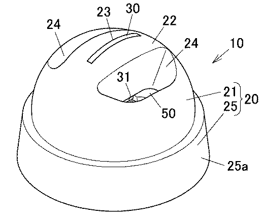
<実施例1〜15>
図1〜11に示した上記第1実施形態の押出成形工具(E1)において、ダイスホルダ(60)のダイス保持孔(62)の周面(62a)のテーパ半角(θ1)と、ダイスホルダ(60)の前端面(60a)に対するダイス(10)の前端部(10b)の突出量(t)とについて表1に示すように様々に変更したものを、準備した。
<Examples 1-15>
In the extrusion tool (E1) of the first embodiment shown in FIGS. 1 to 11, the taper half angle (θ1) of the peripheral surface (62a) of the die holding hole (62) of the die holder (60) and the die holder (60) Various changes were made as shown in Table 1 with respect to the protrusion amount (t) of the front end portion (10b) of the die (10) with respect to the front end surface (60a).
そして、各押出成形工具(E1)を図12,13に示すように上記実施形態と同様な押出成形機(M)にセットして、熱間押出成形を行って、図14,15に示したアルミニウム製中空材(熱交換チューブ60)を製造した。 Then, each extrusion tool (E1) was set in the same extruder (M) as in the above embodiment as shown in FIGS. 12 and 13, and hot extrusion was performed. An aluminum hollow material (heat exchange tube 60) was produced.
そして、ダイス寿命(ダイス(10)に亀裂や磨耗が発生するまでの材料導入量(ton/ダイス))を測定し、更にダイス寿命の制限要因を調査した。その結果を表1に示す。 Then, the die life (the amount of material introduced (ton / die) until cracking or wear occurred on the die (10)) was measured, and the factors limiting the die life were further investigated. The results are shown in Table 1.
ここで、各押出成形工具(E1)のダイス(10)において、ビレット受圧面(22)は、半径30mmの1/2球体の凸球面からなるものである。また、ダイスケース(20)のベース部(25)の後端位置の直径(外径)は65mmに設定されている。またオス型ダイス(30)としては、マンドレル(31)の高さ(厚さ)が2.0mm、マンドレル(31)の幅が19.2mm、通路成形用凸部(33)の高さが1.2mm、通路成形用凸部(33)の幅が0.6mm、隔壁成形用溝(32)の幅が0.2mmのものを用いた。メス型ダイス(40)としては、ダイス孔(41)の高さ(厚さ)が1.7mm、ダイス孔(41)の幅が20.0mmのものを用いた。また、ポート孔(24)の個数は2個、各ポート孔(24)の軸心(A2)の傾斜角度(θ)は20°である。 Here, in the die (10) of each extrusion tool (E1), the billet pressure-receiving surface (22) is a half spherical convex spherical surface having a radius of 30 mm. The diameter (outer diameter) of the rear end position of the base portion (25) of the die case (20) is set to 65 mm. Further, as the male die (30), the height (thickness) of the mandrel (31) is 2.0 mm, the width of the mandrel (31) is 19.2 mm, and the height of the passage molding convex part (33) is 1. .2 mm, the width of the convex part for forming a passage (33) was 0.6 mm, and the width of the groove for forming a partition wall (32) was 0.2 mm. A female die (40) having a die hole (41) height (thickness) of 1.7 mm and a die hole (41) width of 20.0 mm was used. The number of port holes (24) is two, and the inclination angle (θ) of the axis (A2) of each port hole (24) is 20 °.
また、ダイスケース(20)の材質はSKD61、オス型ダイス(30)の材質はWC−Co、メス型ダイス(40)の材質はWC−Coである。 The material of the die case (20) is SKD61, the material of the male die (30) is WC-Co, and the material of the female die (40) is WC-Co.
<比較例1>
押出成形工具のダイスとして、直径60mm、高さ(押出方向の長さ)50mmで、上記実施例4の押出成形工具(E1)のダイス(10)と同一の占有体積を有し、ビレット受圧面が押出方向に対し直交する平坦面に仕上げられたブリッジタイプのダイスを準備した。
<Comparative Example 1>
The die of the extrusion tool has a diameter of 60 mm, a height (length in the extrusion direction) of 50 mm, the same occupied volume as the die (10) of the extrusion tool (E1) of Example 4, and a billet pressure receiving surface Was prepared as a bridge type die finished with a flat surface perpendicular to the extrusion direction.
この押出成形工具のブリッジタイプのダイスにおいて、オス型ダイスのマンドレルの寸法、通路成形用凸部の寸法、隔壁成形用溝の寸法、および押出孔の寸法は、実施例4のダイス(10)と同じである。さらに、ダイスケースの材質およびオス型ダイスの材質は、実施例4のダイス(10)と同じである。 In the bridge type die of this extrusion molding tool, the dimensions of the mandrel of the male die, the dimension of the projection for passage molding, the dimension of the partition molding groove, and the dimension of the extrusion hole are the same as those of the die (10) of Example 4. The same. Further, the material of the die case and the material of the male die are the same as those of the die (10) of the fourth embodiment.
また、この押出成形工具において、ダイスホルダ(60)のダイス保持孔(62)の周面(62a)はテーパ面に形成されたものではなく(すなわちテーパ半角θ1=0°)、また、ダイスの前端部はダイスホルダ(60)の前端面(60a)よりも前方に突出していない(すなわち突出量t=0mm)ものである。 In this extrusion molding tool, the peripheral surface (62a) of the die holding hole (62) of the die holder (60) is not formed into a tapered surface (that is, a taper half angle θ1 = 0 °), and the front end of the die The portion does not protrude forward from the front end surface (60a) of the die holder (60) (that is, the protruding amount t = 0 mm).
そして、この押出成形工具を用いて実施例1と同じ条件で押出成形を行って、中空材(90)を製造した。 Then, using this extrusion molding tool, extrusion molding was performed under the same conditions as in Example 1 to produce a hollow material (90).
そして、ダイス寿命を測定し、更にダイス寿命の制限要因を調査した。その結果を表1に示す。 Then, the die life was measured, and further the limiting factors of the die life were investigated. The results are shown in Table 1.
<実施例1〜15、比較例1の評価>
表1に示すように、実施例1〜15の押出成形工具(E1)は、比較例1の押出成形工具に比べて、ダイス寿命が格段に長いことを確認し得た。
<Evaluation of Examples 1 to 15 and Comparative Example 1>
As shown in Table 1, it was confirmed that the extrusion tool (E1) of Examples 1 to 15 had a much longer die life than the extrusion tool of Comparative Example 1.
また、実施例1〜15の押出成形工具(E1)のうち、実施例1のものは、ダイスホルダ(60)のダイス保持孔(62)の周面(62a)のテーパ半角(θ1)が小さすぎるため、本発明の効果を十分に得ることができず、比較的ダイス寿命が短かった。 Moreover, among the extrusion molding tools (E1) of Examples 1 to 15, in Example 1, the taper half angle (θ1) of the peripheral surface (62a) of the die holding hole (62) of the die holder (60) is too small. For this reason, the effects of the present invention cannot be sufficiently obtained, and the die life is relatively short.
また、実施例1〜15の押出成形工具(E1)のうち、実施例8のものは、ダイスホルダ(60)のダイス保持孔(62)の周面(62a)のテーパ半角(θ1)が大きすぎるため、ダイス保持孔(62)の周面(62a)からダイス(10)のダイスケース(20)の前部(すなわちベース部(25))に加わる縮径方向の圧縮力(C)が大きすぎ、その結果、メス型ダイス(40)に亀裂が発生した。 In addition, among the extrusion molding tools (E1) of Examples 1 to 15, the taper half angle (θ1) of the peripheral surface (62a) of the die holding hole (62) of the die holder (60) is too large. For this reason, the compressive force (C) in the reduced diameter direction applied from the peripheral surface (62a) of the die holding hole (62) to the front portion (that is, the base portion (25)) of the die case (20) of the die (10) is too large. As a result, a crack occurred in the female die (40).
また、実施例1〜15の押出成形工具(E1)のうち、実施例9のものは、ダイス(10)の前端部(10b)の突出量(t)が小さすぎるため、本発明の効果を十分に得ることができず、比較的ダイス寿命が短かった。 Moreover, since the protrusion amount (t) of the front-end part (10b) of die | dye (10) is too small, the thing of Example 9 among the extrusion-molding tools (E1) of Examples 1-15 has the effect of this invention. It could not be obtained sufficiently, and the die life was relatively short.
また、実施例1〜15の押出成形工具(E1)のうち、実施例15のものは、ダイス(10)の前端部(10b)の突出量(t)が大きすぎるため、ダイス保持孔(62)の周面(62a)からダイス(10)のダイスケース(20)の前部(すなわちベース部(25))に加わる縮径方向の圧縮力(C)が大きすぎ、その結果、メス型ダイス(40)に亀裂が発生した。 Moreover, since the protrusion amount (t) of the front-end part (10b) of the die (10) is too large in the extrusion tool (E1) of Examples 1 to 15, the die holding hole (62 ) From the peripheral surface (62a) to the front portion (ie, the base portion (25)) of the die case (20) of the die (10) is too large. As a result, the female die Cracks occurred in (40).
したがって、実施例1〜15の押出成形工具(E1)のうち、実施例2〜8、および10〜14のものが、特に優れた耐久性を有するものであることが分かった。 Therefore, it turned out that the thing of Examples 2-8 and 10-14 has especially outstanding durability among the extrusion-molding tools (E1) of Examples 1-15.
<実施例16>
表2に示すように上記実施形態に準拠して、押出成形工具(E1)のダイス(10)のダイスケース(20)として、ビレット受圧面(22)が、1/8球体の凸球面によって構成され、その球面半径が45.4mmに設定されたものを準備した。この受圧部(21)の直径は60mmに調整されている。
<Example 16>
As shown in Table 2, the billet pressure-receiving surface (22) is constituted by a convex spherical surface of a 1/8 sphere as the die case (20) of the die (10) of the extrusion tool (E1) as shown in Table 2. The spherical radius was set to 45.4 mm. The diameter of the pressure receiving portion (21) is adjusted to 60 mm.
さらに、ダイスケース(20)は、2つのポート孔(24)(24)を有し、ダイスケース(20)の軸心(A1)に対しポート孔(24)の軸心(A2)の傾斜角度(θ)が25°に調整されている。 Furthermore, the die case (20) has two port holes (24) and (24), and the inclination angle of the axis (A2) of the port hole (24) with respect to the axis (A1) of the die case (20). (Θ) is adjusted to 25 °.
またオス型ダイス(30)としては、マンドレル(31)の高さ(厚さ)が2.0mm、マンドレル(31)の幅が19.2mm、通路成形用凸部(33)の高さが1.2mm、通路成形用凸部(33)の幅が0.6mm、隔壁成形用溝(32)の幅が0.2mmのものを用いた。さらにメス型ダイス(40)としては、ダイス孔(41)の高さが1.7mm、ダイス孔(41)の幅が20.0mmのものを用いた。 Further, as the male die (30), the height (thickness) of the mandrel (31) is 2.0 mm, the width of the mandrel (31) is 19.2 mm, and the height of the passage molding convex part (33) is 1. .2 mm, the width of the convex part for forming a passage (33) was 0.6 mm, and the width of the groove for forming a partition wall (32) was 0.2 mm. Further, as the female die (40), one having a die hole (41) height of 1.7 mm and a die hole (41) width of 20.0 mm was used.
また、この押出成形工具(E1)において、ダイスホルダ(60)のダイス保持孔(62)の周面(62a)のテーパ半角(θ1)は5°に設定されており、またダイス(10)の前端部(10b)の突出量(t)は2.0mmに設定されている。 In the extrusion tool (E1), the taper half angle (θ1) of the peripheral surface (62a) of the die holding hole (62) of the die holder (60) is set to 5 °, and the front end of the die (10) The protrusion amount (t) of the portion (10b) is set to 2.0 mm.
そして、この押出成形工具(E1)を図12,13に示すように上記実施形態と同様な押出成形機(M)にセットして、熱間押出成形を行って、図14,15に示したアルミニウム製中空材(熱交換チューブ90)を製造した。 And this extrusion tool (E1) was set in the same extrusion molding machine (M) as the above-mentioned embodiment as shown in FIGS. 12 and 13, and hot extrusion molding was performed, and shown in FIGS. An aluminum hollow material (heat exchange tube 90) was produced.
そして、ダイス寿命を測定した。その結果を表2に示す。 Then, the die life was measured. The results are shown in Table 2.
<実施例17>
表2に示すように、押出成形工具(E1)のダイス(10)として、ビレット受圧面(22)を、1/6球体の凸球面によって構成し、かつその球面半径を40.3mmに設定し、それ以外は、上記実施例16と同様のダイス(10)を準備した。また、この押出成形工具(E1)において、ダイスホルダ(60)のダイス保持孔(62)の周面(62a)のテーパ半角(θ1)およびダイス(10)の前端部(10b)の突出量(t)は、実施例16と同じである。そして、この押出成形工具(E1)を上記実施形態と同様な押出成形機(M)にセットして、同様に熱間押出成形を行って、中空材(90)を製造した。
<Example 17>
As shown in Table 2, as the die (10) of the extrusion tool (E1), the billet pressure receiving surface (22) is constituted by a convex spherical surface of 1/6 sphere, and the spherical radius is set to 40.3 mm. Other than that, the dice | dies (10) similar to the said Example 16 were prepared. Further, in the extrusion tool (E1), the taper half angle (θ1) of the peripheral surface (62a) of the die holding hole (62) of the die holder (60) and the protruding amount (t) of the front end portion (10b) of the die (10) (t) ) Is the same as in Example 16. And this extrusion tool (E1) was set to the same extrusion molding machine (M) as the said embodiment, the hot extrusion molding was performed similarly, and the hollow material (90) was manufactured.
<実施例18>
表2に示すように、押出成形工具(E1)のダイス(10)として、ビレット受圧面(22)を、1/3球体の凸球面によって構成し、かつその球面半径を32.0mmに設定し、それ以外は、上記実施例16と同様のダイス(10)を準備した。また、この押出成形工具(E1)において、ダイスホルダ(60)のダイス保持孔(62)の周面(62a)のテーパ半角(θ1)およびダイス(10)の前端部(10b)の突出量(t)は、実施例16と同じである。そして、この押出成形工具(E1)を上記実施形態と同様な押出成形機(M)にセットして、同様に熱間押出成形を行って、中空材(90)を製造した。
<Example 18>
As shown in Table 2, as the die (10) of the extrusion tool (E1), the billet pressure-receiving surface (22) is constituted by a convex spherical surface of 1/3 sphere, and the spherical radius is set to 32.0 mm. Other than that, the dice | dies (10) similar to the said Example 16 were prepared. Further, in the extrusion tool (E1), the taper half angle (θ1) of the peripheral surface (62a) of the die holding hole (62) of the die holder (60) and the protruding amount (t) of the front end portion (10b) of the die (10) (t) ) Is the same as in Example 16. And this extrusion tool (E1) was set to the same extrusion molding machine (M) as the said embodiment, the hot extrusion molding was performed similarly, and the hollow material (90) was manufactured.
<実施例19>
表2に示すように、押出成形工具(E1)のダイス(10)として、ビレット受圧面(22)を、1/2球体の凸球面によって構成し、かつその球面半径を30.0mmに設定し、それ以外は、上記実施例16と同様のダイス(10)を準備した。また、この押出成形工具(E1)において、ダイスホルダ(60)のダイス保持孔(62)の周面(62a)のテーパ半角(θ1)およびダイス(10)の前端部(10b)の突出量(t)は、実施例16と同じである。そして、この押出成形工具(E1)を上記実施形態と同様な押出成形機(M)に設定して、同様に熱間押出成形を行って、中空材(90)を製造した。
<Example 19>
As shown in Table 2, as the die (10) of the extrusion tool (E1), the billet pressure receiving surface (22) is constituted by a convex spherical surface of a half sphere, and the spherical radius is set to 30.0 mm. Other than that, the dice | dies (10) similar to the said Example 16 were prepared. Further, in the extrusion tool (E1), the taper half angle (θ1) of the peripheral surface (62a) of the die holding hole (62) of the die holder (60) and the protruding amount (t) of the front end portion (10b) of the die (10) (t) ) Is the same as in Example 16. And this extrusion tool (E1) was set to the same extrusion molding machine (M) as the said embodiment, hot extrusion molding was performed similarly, and the hollow material (90) was manufactured.
<実施例20>
表2に示すように、押出成形工具(E1)のダイス(10)として、ビレット受圧面(22)を、4/6球体の凸球面によって構成し、かつその球面半径を32.0mmに設定し、それ以外は、上記実施例16と同様のダイス(10)を準備した。また、この押出成形工具(E1)において、ダイスホルダ(60)のダイス保持孔(62)の周面(62a)のテーパ半角(θ1)およびダイス(10)の前端部(10b)の突出量(t)は、実施例16と同じである。そして、この押出成形工具(E1)を上記実施形態と同様な押出成形機(M)にセットして、同様に熱間押出成形を行って、中空材(90)を製造した。
<Example 20>
As shown in Table 2, as the die (10) of the extrusion tool (E1), the billet pressure receiving surface (22) is constituted by a convex spherical surface of 4/6 sphere, and the spherical radius is set to 32.0 mm. Other than that, the dice | dies (10) similar to the said Example 16 were prepared. Further, in the extrusion tool (E1), the taper half angle (θ1) of the peripheral surface (62a) of the die holding hole (62) of the die holder (60) and the protruding amount (t) of the front end portion (10b) of the die (10) (t) ) Is the same as in Example 16. And this extrusion tool (E1) was set to the same extrusion molding machine (M) as the said embodiment, the hot extrusion molding was performed similarly, and the hollow material (90) was manufactured.
<実施例21>
表2に示すように、押出成形工具(E1)のダイス(10)として、ビレット受圧面(22)を、5/6球体の凸球面によって構成し、かつその球面半径を40.3mmに設定し、それ以外は、上記実施例16と同様のダイス(10)を準備した。また、この押出成形工具(E1)において、ダイスホルダ(60)のダイス保持孔(62)の周面(62a)のテーパ半角(θ1)およびダイス(10)の前端部(10b)の突出量(t)は、実施例16と同じである。そして、この押出成形工具(E1)を上記実施形態と同様の押出成形機(M)にセットして、同様に熱間押出成形を行って、中空材(90)を製造した。
<Example 21>
As shown in Table 2, as a die (10) of the extrusion tool (E1), the billet pressure receiving surface (22) is constituted by a convex spherical surface of a 5/6 sphere, and the spherical radius is set to 40.3 mm. Other than that, the dice | dies (10) similar to the said Example 16 were prepared. Further, in the extrusion tool (E1), the taper half angle (θ1) of the peripheral surface (62a) of the die holding hole (62) of the die holder (60) and the protruding amount (t) of the front end portion (10b) of the die (10) (t) ) Is the same as in Example 16. And this extrusion tool (E1) was set to the same extrusion molding machine (M) as the said embodiment, the hot extrusion molding was performed similarly, and the hollow material (90) was manufactured.
<実施例16〜21の評価>
表2に示すように、押出成形工具(E1)のダイス(10)のビレット受圧面(22)における球面半径が大きくて突出量が比較的小さいもの(実施例6)では、ダイス寿命が少し短くなっていた。
<Evaluation of Examples 16 to 21>
As shown in Table 2, when the spherical radius of the billet pressure receiving surface (22) of the die (10) of the extrusion tool (E1) is large and the protrusion amount is relatively small (Example 6), the die life is slightly short. It was.
さらにビレット受圧面(22)における球面半径が小さくて球体の突出量が比較的大きいもの(実施例11)では、ダイス寿命を長く確保できるが、ビレット受圧面(22)の加工が若干困難であると考えられる。 Further, when the spherical radius on the billet pressure receiving surface (22) is small and the protruding amount of the sphere is relatively large (Example 11), it is possible to ensure a long die life, but it is slightly difficult to process the billet pressure receiving surface (22). it is conceivable that.
これに対し、ビレット受圧面(22)が、適度な凸面形状に設定されたもの、つまり1/6〜4/6球体の凸球面に設定されたもの(実施例17〜20)では、ダイス寿命を長くできる上さらに、ダイス制作費も抑えることができた。中でも特にビレット受圧面(22)が、1/2球体の凸球面に設定されたもの(実施例19)では、十分なダイス寿命を確保しつつ、ダイス制作費も抑えることができ、優れた結果が得られた。 On the other hand, when the billet pressure-receiving surface (22) is set to an appropriate convex shape, that is, a convex spherical surface of 1/6 to 4/6 sphere (Examples 17 to 20), the die life is increased. In addition to lengthening the production time, the production costs for the dice were also reduced. In particular, when the billet pressure-receiving surface (22) is set to a half spherical convex spherical surface (Example 19), the die production cost can be reduced while securing a sufficient die life, and excellent results. was gotten.
なお実施例19のものと比較すると、ビレット受圧面(22)が、4/6球体の凸球面に設定されたもの(実施例20)では多少、ダイス制作費が高くなり、実施例16〜20の中では、若干見劣りした結果となった。 In addition, compared with the thing of Example 19, when a billet pressure-receiving surface (22) is set to the convex spherical surface of a 4/6 sphere (Example 20), die production costs become somewhat high, and Examples 16-20 Among them, the results were slightly inferior.
この発明の金属材料の押出成形工具は、例えばカーエアコン用コンデンサなどの熱交換器における熱交換チューブを製造する際に採用できる。 The metal material extrusion tool of the present invention can be employed when manufacturing a heat exchange tube in a heat exchanger such as a condenser for a car air conditioner, for example.
M…押出成形機
E1…押出成形工具
6…コンテナ
10…ダイス
10a…前端面
10b…前端部
11…押出孔
20…ダイスケース
21…受圧部
22…ビレット受圧面(金属材料受圧面)
23…オス型ダイス保持孔
24…ポート孔
25…ベース部(ダイスケースの前部)
25a…外周面
26…メス型ダイス保持孔
30…オス型ダイス
31…マンドレル
33…通路形成用凸部
40…メス型ダイス
41…ダイス孔
60…ダイスホルダ
62…ダイス保持孔
62a…周面
80…バッカ
90…中空材
93…通路
A1…ダイスケース(受圧部)の軸心
A2…ポート孔の軸心
θ1…ダイス保持孔の周面のテーパ半角
θ2…ポート孔の軸心の傾斜角度
t…ダイスの前端部の突出量
M ... Extruder E1 ...
23 ... Male die holding
25a ... outer
Claims (18)
ダイス保持孔内に挿入保持されたダイスと、
ダイスの前側に該ダイスの前端面に当接して配置されたバッカと、を備えた金属材料の押出成形工具であって、
ダイスは、
外表面を金属材料受圧面とする受圧部を有し、その受圧部の金属材料受圧面を金属材料の押出方向に対向させるように後方に向けて配置されるダイスケースと、
ダイスケースの内部に保持され、かつダイスケースの軸心に対応して配置されるマンドレルを有するオス型ダイスと、
ダイスケース内の前部に保持され、かつマンドレルとの間で押出孔を形成するダイス孔が設けられたメス型ダイスと、を備え、さらに、
受圧部における金属材料受圧面が後方に向けて突出する凸面形状に形成される一方、
受圧部の外周に、金属材料導入用のポート孔が設けられるとともに、そのポート孔の軸心が下流側に向かうに従ってダイスケースの軸心に近づくように、ダイスケースの軸心に対し傾斜するように配置され、且つ、
金属材料受圧面に押圧された金属材料が、ポート孔を通ってダイスケース内に導かれて、押出孔を通過するよう構成されており、
ダイスホルダのダイス保持孔の周面は、下流側に向かうに従って漸次拡径するテーパ面に形成されるとともに、
ダイスホルダのダイス保持孔の周面に当接する、ダイスのダイスケースの前部の外周面は、ダイス保持孔の周面に対応したテーパ面に形成されたことを特徴とする金属材料の押出成形工具。 A die holder having a die holding hole;
A die inserted and held in the die holding hole;
A metal material extrusion tool comprising a backer disposed on the front side of the die in contact with the front end surface of the die,
Dice
A die case having a pressure receiving portion having an outer surface as a metal material pressure receiving surface, and disposed rearward so that the metal material pressure receiving surface of the pressure receiving portion faces the extrusion direction of the metal material;
A male die having a mandrel held inside the die case and arranged corresponding to the axis of the die case;
A female die that is held at the front part in the die case and provided with a die hole that forms an extrusion hole with the mandrel, and further,
While the metal material pressure receiving surface in the pressure receiving portion is formed in a convex shape protruding backward,
A port hole for introducing a metal material is provided on the outer periphery of the pressure receiving portion, and the port hole is inclined with respect to the axis of the die case so that the axis of the port hole approaches the axis of the die case as it goes downstream. And
The metal material pressed against the metal material pressure receiving surface is configured to be guided into the die case through the port hole and pass through the extrusion hole.
The peripheral surface of the die holding hole of the die holder is formed into a tapered surface that gradually increases in diameter toward the downstream side,
A metal material extrusion tool characterized in that the outer peripheral surface of the front portion of the die case of the die that is in contact with the peripheral surface of the die holding hole of the die holder is formed into a tapered surface corresponding to the peripheral surface of the die holding hole. .
オス型ダイスのマンドレルと、メス型ダイスのダイス孔との間によって、高さ(厚さ)が幅に対し小さい偏平な環状の押出孔が形成されるとともに、
マンドレルにおけるダイス孔に対応する部分が、幅方向に併設された複数の通路成形用凸部を有する櫛歯状に形成されて、
金属材料が押出孔を通過することによって、複数の通路が幅方向に併設された多孔中空材が成形されるよう構成された請求項1〜8のいずれか1項に記載の金属材料の押出成形工具。 Dice
Between the mandrel of the male die and the die hole of the female die, a flat annular extrusion hole whose height (thickness) is smaller than the width is formed,
The portion corresponding to the die hole in the mandrel is formed in a comb-teeth shape having a plurality of passage molding convex portions provided side by side in the width direction,
The metal material extrusion molding according to any one of claims 1 to 8, wherein a porous hollow material in which a plurality of passages are arranged in the width direction is formed by passing the metal material through the extrusion hole. tool.
ポート孔が押出孔の高さ方向(厚さ方向)両側に対応する位置に配置された請求項1〜10のいずれか1項に記載の金属材料の押出成形工具。 A flat annular extrusion hole whose height is smaller than the width is formed between the mandrel of the male die of the die and the die hole of the female die,
The metal material extrusion tool according to any one of claims 1 to 10, wherein the port holes are arranged at positions corresponding to both sides of the height direction (thickness direction) of the extrusion holes.
Priority Applications (1)
| Application Number | Priority Date | Filing Date | Title |
|---|---|---|---|
| JP2007056608A JP4938501B2 (en) | 2007-03-07 | 2007-03-07 | Metal material extrusion tool |
Applications Claiming Priority (1)
| Application Number | Priority Date | Filing Date | Title |
|---|---|---|---|
| JP2007056608A JP4938501B2 (en) | 2007-03-07 | 2007-03-07 | Metal material extrusion tool |
Publications (2)
| Publication Number | Publication Date |
|---|---|
| JP2008213010A JP2008213010A (en) | 2008-09-18 |
| JP4938501B2 true JP4938501B2 (en) | 2012-05-23 |
Family
ID=39833678
Family Applications (1)
| Application Number | Title | Priority Date | Filing Date |
|---|---|---|---|
| JP2007056608A Expired - Fee Related JP4938501B2 (en) | 2007-03-07 | 2007-03-07 | Metal material extrusion tool |
Country Status (1)
| Country | Link |
|---|---|
| JP (1) | JP4938501B2 (en) |
Cited By (1)
| Publication number | Priority date | Publication date | Assignee | Title |
|---|---|---|---|---|
| US11498104B2 (en) | 2019-08-05 | 2022-11-15 | Samsung Electronics Co., Ltd. | Extrusion apparatus and method for manufacturing aluminum capillary tube using same |
Families Citing this family (2)
| Publication number | Priority date | Publication date | Assignee | Title |
|---|---|---|---|---|
| CN110000234A (en) * | 2018-12-29 | 2019-07-12 | 江阴市江顺模具有限公司 | A kind of sound equipment material aluminium alloy hot-extrusion die |
| CN116727476B (en) * | 2023-08-15 | 2023-11-07 | 中北大学 | A method for forming magnesium alloy tail radial synchronous loading |
Family Cites Families (10)
| Publication number | Priority date | Publication date | Assignee | Title |
|---|---|---|---|---|
| FR2082001A5 (en) * | 1969-12-08 | 1971-12-10 | Creuzet Robert | |
| JPS5085552A (en) * | 1973-12-03 | 1975-07-10 | ||
| JPS53102938A (en) * | 1977-02-21 | 1978-09-07 | Kuraray Co Ltd | Pressure sensitive adhesive composition |
| JPS53125742A (en) * | 1977-04-08 | 1978-11-02 | Fujitsu Ltd | Transversal filter of split gate type |
| JPH0681644B2 (en) * | 1989-01-13 | 1994-10-19 | 三協アルミニウム工業株式会社 | Dies for extrusion molding of metal materials |
| JPH057924A (en) * | 1991-07-01 | 1993-01-19 | Showa Alum Corp | Hollow die for extrusion |
| JPH07124633A (en) * | 1993-10-29 | 1995-05-16 | Showa Alum Corp | Hollow material extrusion die |
| JPH1190526A (en) * | 1997-09-16 | 1999-04-06 | Aisin Keikinzoku Co Ltd | Structure of extrusion die for aluminum alloy |
| JP2006142325A (en) * | 2004-11-17 | 2006-06-08 | Kobe Steel Ltd | Bridge die for extruding aluminum alloy shape |
| JP4890163B2 (en) * | 2005-09-08 | 2012-03-07 | 昭和電工株式会社 | Dies for metal material extrusion |
-
2007
- 2007-03-07 JP JP2007056608A patent/JP4938501B2/en not_active Expired - Fee Related
Cited By (1)
| Publication number | Priority date | Publication date | Assignee | Title |
|---|---|---|---|---|
| US11498104B2 (en) | 2019-08-05 | 2022-11-15 | Samsung Electronics Co., Ltd. | Extrusion apparatus and method for manufacturing aluminum capillary tube using same |
Also Published As
| Publication number | Publication date |
|---|---|
| JP2008213010A (en) | 2008-09-18 |
Similar Documents
| Publication | Publication Date | Title |
|---|---|---|
| JP5053662B2 (en) | Dies for metal material extrusion | |
| JP4938500B2 (en) | Dies for metal material extrusion | |
| JP4890163B2 (en) | Dies for metal material extrusion | |
| JP4938501B2 (en) | Metal material extrusion tool | |
| JP5149517B2 (en) | Die assembly tool for extrusion molding | |
| JP5053664B2 (en) | Dies for metal material extrusion | |
| JP4938505B2 (en) | Dies for metal material extrusion | |
| JP5053660B2 (en) | Dies for metal material extrusion | |
| JP5053663B2 (en) | Dies for metal material extrusion | |
| JP4938504B2 (en) | Dies for metal material extrusion | |
| JP4938506B2 (en) | Dies for metal material extrusion | |
| CN101522327B (en) | Extrusion die for metallic material | |
| JP4938503B2 (en) | Dies for metal material extrusion | |
| US20100095731A1 (en) | Extrusion die for metallic material | |
| CN100447380C (en) | Processing and forming method of automobile purifier shell | |
| CN211757689U (en) | Mould of large-scale board class section bar of expanding | |
| US20090293570A1 (en) | Extrusion die for metallic material | |
| CN101216180A (en) | Cigarette lighter nozzle manufacture method and mould for the method | |
| CN105880309A (en) | Insert-type mold for extruding tubes with same pore diameter and different wall thickness | |
| JP4502466B2 (en) | Multi-hole extrusion tool | |
| JPH05131427A (en) | Extrusion molding die for honeycomb structure | |
| Deng et al. | A aluminum alloy extrusion die structure on the large flat tube | |
| JPH09201618A (en) | Hollow product extrusion die |
Legal Events
| Date | Code | Title | Description |
|---|---|---|---|
| A621 | Written request for application examination |
Free format text: JAPANESE INTERMEDIATE CODE: A621 Effective date: 20100113 |
|
| A977 | Report on retrieval |
Free format text: JAPANESE INTERMEDIATE CODE: A971007 Effective date: 20110518 |
|
| TRDD | Decision of grant or rejection written | ||
| A01 | Written decision to grant a patent or to grant a registration (utility model) |
Free format text: JAPANESE INTERMEDIATE CODE: A01 Effective date: 20120201 |
|
| A01 | Written decision to grant a patent or to grant a registration (utility model) |
Free format text: JAPANESE INTERMEDIATE CODE: A01 |
|
| A61 | First payment of annual fees (during grant procedure) |
Free format text: JAPANESE INTERMEDIATE CODE: A61 Effective date: 20120223 |
|
| FPAY | Renewal fee payment (event date is renewal date of database) |
Free format text: PAYMENT UNTIL: 20150302 Year of fee payment: 3 |
|
| R150 | Certificate of patent or registration of utility model |
Free format text: JAPANESE INTERMEDIATE CODE: R150 |
|
| FPAY | Renewal fee payment (event date is renewal date of database) |
Free format text: PAYMENT UNTIL: 20150302 Year of fee payment: 3 |
|
| RD02 | Notification of acceptance of power of attorney |
Free format text: JAPANESE INTERMEDIATE CODE: R3D02 |
|
| LAPS | Cancellation because of no payment of annual fees |