JP4937718B2 - Image forming apparatus - Google Patents
Image forming apparatus Download PDFInfo
- Publication number
- JP4937718B2 JP4937718B2 JP2006331509A JP2006331509A JP4937718B2 JP 4937718 B2 JP4937718 B2 JP 4937718B2 JP 2006331509 A JP2006331509 A JP 2006331509A JP 2006331509 A JP2006331509 A JP 2006331509A JP 4937718 B2 JP4937718 B2 JP 4937718B2
- Authority
- JP
- Japan
- Prior art keywords
- film
- heating
- image forming
- moving
- lubricant
- Prior art date
- Legal status (The legal status is an assumption and is not a legal conclusion. Google has not performed a legal analysis and makes no representation as to the accuracy of the status listed.)
- Expired - Fee Related
Links
Images


Classifications
-
- G—PHYSICS
- G03—PHOTOGRAPHY; CINEMATOGRAPHY; ANALOGOUS TECHNIQUES USING WAVES OTHER THAN OPTICAL WAVES; ELECTROGRAPHY; HOLOGRAPHY
- G03G—ELECTROGRAPHY; ELECTROPHOTOGRAPHY; MAGNETOGRAPHY
- G03G15/00—Apparatus for electrographic processes using a charge pattern
- G03G15/65—Apparatus which relate to the handling of copy material
- G03G15/6588—Apparatus which relate to the handling of copy material characterised by the copy material, e.g. postcards, large copies, multi-layered materials, coloured sheet material
- G03G15/6591—Apparatus which relate to the handling of copy material characterised by the copy material, e.g. postcards, large copies, multi-layered materials, coloured sheet material characterised by the recording material, e.g. plastic material, OHP, ceramics, tiles, textiles
-
- G—PHYSICS
- G03—PHOTOGRAPHY; CINEMATOGRAPHY; ANALOGOUS TECHNIQUES USING WAVES OTHER THAN OPTICAL WAVES; ELECTROGRAPHY; HOLOGRAPHY
- G03G—ELECTROGRAPHY; ELECTROPHOTOGRAPHY; MAGNETOGRAPHY
- G03G15/00—Apparatus for electrographic processes using a charge pattern
- G03G15/20—Apparatus for electrographic processes using a charge pattern for fixing, e.g. by using heat
- G03G15/2003—Apparatus for electrographic processes using a charge pattern for fixing, e.g. by using heat using heat
- G03G15/2014—Apparatus for electrographic processes using a charge pattern for fixing, e.g. by using heat using heat using contact heat
- G03G15/2017—Structural details of the fixing unit in general, e.g. cooling means, heat shielding means
- G03G15/2025—Structural details of the fixing unit in general, e.g. cooling means, heat shielding means with special means for lubricating and/or cleaning the fixing unit, e.g. applying offset preventing fluid
-
- G—PHYSICS
- G03—PHOTOGRAPHY; CINEMATOGRAPHY; ANALOGOUS TECHNIQUES USING WAVES OTHER THAN OPTICAL WAVES; ELECTROGRAPHY; HOLOGRAPHY
- G03G—ELECTROGRAPHY; ELECTROPHOTOGRAPHY; MAGNETOGRAPHY
- G03G2215/00—Apparatus for electrophotographic processes
- G03G2215/00362—Apparatus for electrophotographic processes relating to the copy medium handling
- G03G2215/00443—Copy medium
- G03G2215/00493—Plastic
-
- G—PHYSICS
- G03—PHOTOGRAPHY; CINEMATOGRAPHY; ANALOGOUS TECHNIQUES USING WAVES OTHER THAN OPTICAL WAVES; ELECTROGRAPHY; HOLOGRAPHY
- G03G—ELECTROGRAPHY; ELECTROPHOTOGRAPHY; MAGNETOGRAPHY
- G03G2215/00—Apparatus for electrophotographic processes
- G03G2215/20—Details of the fixing device or porcess
- G03G2215/2093—Release agent handling devices
Description
本発明は、加熱体に圧接されたフィルム体を介在させて被加熱材を加熱するように構成された加熱装置及び画像形成装置に関する。 The present invention relates to a heating apparatus and an image forming apparatus configured to heat a material to be heated by interposing a film body pressed against a heating body.
一般に、適宜の加熱体に対してフィルム体を介して被加熱材を圧接させ、当該被加熱材を前記フィルム体とともに移動させながら加熱する構成を備えた加熱装置が種々の装置で用いられている。例えば、電子写真方式によるプリンター、複写機、ファクシミリなどの各種画像形成装置では、感光ドラムなどの像担持体から記録材側に転写された未定着トナー像の定着を行う接触加熱方式の加熱定着装置が採用されているが、その加熱定着装置において、近年の省エネルギー等の観点から、熱容量の小さな定着フィルムを介して記録材を加熱するようにしたフィルム加熱定着方式が広く採用されつつある。フィルム加熱定着方式によれば、熱容量が小さく熱伝達効率が高い定着フィルムを、ヒータ等の加熱体と被加熱材としての記録材との間に介在させることによって、装置の立ち上がり時間の短縮化を図ることが可能となるとともに、消費電力を低減することが可能となる。 In general, a heating device having a configuration in which a material to be heated is pressed against an appropriate heating body through a film body and heated while being moved together with the film body is used in various apparatuses. . For example, in various image forming apparatuses such as electrophotographic printers, copiers, and facsimiles, a contact heating heating fixing device that fixes an unfixed toner image transferred from an image carrier such as a photosensitive drum to the recording material side. However, from the viewpoint of energy saving and the like in recent years, a film heat fixing method in which a recording material is heated through a fixing film having a small heat capacity is being widely adopted in the heat fixing apparatus. According to the film heating and fixing method, the rise time of the apparatus can be shortened by interposing a fixing film having a small heat capacity and high heat transfer efficiency between a heating body such as a heater and a recording material as a material to be heated. As a result, power consumption can be reduced.
このようなフィルム定着方式を採用した加熱定着装置では、本発明の一実施形態にかかる図2及び図3のように、加熱支持部材118dの摺動表面(図示下面)の一部に露出するようにして加熱体118eが取り付けられており、その加熱体118eの加熱表面(図示下面)に対して、環状移動自在に配置された定着フィルム118aを介して加圧ローラ118bが図示下方側から圧接されており、その加圧ローラ118bの回転駆動によって上記定着フィルム118a及び被加熱材としての記録材Pが従動的に移動されながら上記記録材P上の未定着トナーTの加熱定着作用が行われるようになっている。
In the heat fixing apparatus employing such a film fixing method, as shown in FIGS. 2 and 3 according to one embodiment of the present invention, the
このとき、上述した定着フィルム118aの移動が円滑に行われるように、グリース等の適宜の潤滑剤が上記定着フィルム118aの内面側に塗布されており、当該定着フィルム118aと、前記加熱支持部材118dの摺動表面及び前記加熱体118eの加熱表面との間に、グリース等の潤滑剤が介在されていることによって、両部材どうしの摺動性が向上されるようになっている。
At this time, an appropriate lubricant such as grease is applied to the inner surface side of the
ところが、このようなグリース等からなる潤滑剤は、加熱・昇温されるに従って粘度が下がり、流動性が高くなっていく傾向があるとともに、被加熱材としての記録材Pを通過させるときに適宜の圧力が付与されるために、使用時間の経過とともに定着フィルム118aの移動方向に直交する長手方向(画像形成幅方向)の中央領域から外方領域に向かって潤滑剤が移動していき、定着フィルム118aの長手方向両端部から潤滑剤が外方に溢れ出してしまう場合がある。このようにして外部漏れした潤滑剤は、定着フィルム118aの外表面に付着して記録材Pの離型性を低下させたり、記録材Pの表面に潤滑剤が付着してその付着跡が画像として形成されてしまったりするなど、画像品質の低下を引き起こす原因となるおそれがある。
However, such a lubricant made of grease or the like tends to decrease in viscosity and increase in fluidity as it is heated and heated, and is appropriately used when passing the recording material P as the material to be heated. Therefore, the lubricant moves from the central region in the longitudinal direction (image forming width direction) perpendicular to the moving direction of the
特に、小幅サイズの記録材Pが発熱体の長手方向(画像形成幅方向)の中央領域に対して連続的に通紙される場合には、記録材Pの通過部位である中央領域の温度に対して、非通過部位である両端領域の温度が上昇することとなり、その温度上昇に伴って流動性が高められた両端領域(非通過部位)の潤滑剤が、上記定着フィルム118aの長手方向両端部から外部漏れすることが多い。その結果、両端領域の潤滑剤量が減少して中央領域と両端領域との間で潤滑剤の保持量の分布にムラが発生し、潤滑剤量が減少した両端領域では、定着フィルム118aと加熱体118eとの間の摺動性が悪化して定着フィルム118aの内面が傷付いて異音を発生させるとともに、潤滑剤量の減少が装置寿命の短縮化の原因となることもある。
In particular, when the recording material P having a small width is continuously passed through the central region in the longitudinal direction (image forming width direction) of the heating element, the temperature of the central region that is the passage portion of the recording material P is maintained. On the other hand, the temperature of both end regions, which are non-passing portions, increases, and the lubricant in the both end regions (non-passing portions) whose fluidity has been increased along with the temperature rise, the longitudinal ends of the
このような問題を解決するため、例えば下記の特許文献1に開示された加熱装置では、加熱体の上流側に複数のボス又は溝を設け、それによって定着フィルムの両端部からのグリース(潤滑剤)の染み出しを防ぐようにしている。しかしながら、当該装置では、加熱温度が比較的低く潤滑剤の流動性が良好でない領域、すなわち定着フィルム移動方向の上流側にボスや溝が配置されているために、潤滑剤を長手方向に十分拡散することができなくなっており、潤滑剤が中央領域に集中する傾向が生じてボスや溝に対する定着フィルムの摩擦が大きくなっている。 In order to solve such a problem, for example, in the heating device disclosed in Patent Document 1 below, a plurality of bosses or grooves are provided on the upstream side of the heating body, whereby grease (lubricant) from both ends of the fixing film is provided. ) To prevent seepage. However, in this device, the lubricant is sufficiently diffused in the longitudinal direction because bosses and grooves are arranged in the region where the heating temperature is relatively low and the fluidity of the lubricant is not good, that is, upstream in the moving direction of the fixing film. As a result, the lubricant tends to concentrate in the central region, and the friction of the fixing film with respect to the bosses and grooves increases.
そこで本発明は、簡易な構成で、定着フィルム等のフィルム体移動方向に直交する方向における潤滑剤の分散を促進して潤滑剤漏れをなくして装置の長寿命化を図るとともに、潤滑剤漏れによる汚染や潤滑剤不足による異音の発生を防止することができるようにした加熱装置及び画像形成装置を提供することを目的とする。 Therefore, the present invention has a simple configuration and promotes the dispersion of the lubricant in the direction orthogonal to the moving direction of the film body such as a fixing film, thereby eliminating the lubricant leakage and extending the life of the device. It is an object of the present invention to provide a heating device and an image forming apparatus capable of preventing the generation of abnormal noise due to contamination or lack of lubricant.
上記目的を達成するため本発明にかかる画像形成装置では、加熱支持部材の摺動表面の一部に露出するようにして配置された加熱体の加熱表面にフィルム状移動体を介して記録材を圧接させ、当該記録材を前記フィルム状移動体とともに移動させながら加熱を行う定着装置を備え、前記記録材に画像を形成する画像形成装置において、前記定着装置は、前記加熱支持部材の摺動表面及び前記加熱体の加熱表面と、前記フィルム状移動体との間に潤滑剤を有し、前記加熱支持部材の摺動表面には、前記フィルム状移動体の移動方向における前記加熱体の下流側に、前記記録材の幅方向に複数条にわたって前記潤滑剤を案内する案内溝が設けられ、前記複数条の案内溝の配置間隔は、前記記録材のサイズによって当該記録材が通過しない場合がある前記幅方向の外方領域が中央領域より狭く設定され、且つ前記幅方向における両端の前記案内溝が、前記移動方向に沿って前記外方領域から中央領域に向かって傾斜している。 In order to achieve the above object, in the image forming apparatus according to the present invention, the recording material is placed on the heating surface of the heating body arranged so as to be exposed at a part of the sliding surface of the heating support member via the film- like moving body. In an image forming apparatus that includes a fixing device that heats the recording material while being pressed and moved together with the film- like moving body, and that forms an image on the recording material, the fixing device includes a sliding surface of the heating support member and a heating surface of the heating body has a lubricant between the film-like moving member, said the sliding surface of the heating support member, downstream of the heating body in the moving direction of the film-like moving member in the guide groove for guiding the lubricant are provided over plural rows in the width direction of the recording material, the arrangement interval of the guide groove of the plural rows, the case where the recording medium by the size of the recording material does not pass there The width outer region of the direction is set narrower than the central region, said guide groove at both ends and in the width direction are inclined toward the central area from the outer area along the moving direction.
このような構成を有する本発明にかかる画像形成装置よれば、加熱温度が比較的高く潤滑剤の流動性が高められているフィルム状移動体の移動方向の下流側に位置する加熱支持部材の摺動表面に、潤滑剤を均一案内して分散させる案内溝が設けられていることから、加熱支持部材及びフィルム体の両端領域から中央領域にかけての全領域にわたって潤滑剤が良好に拡散されて均一分散されることとなり、フィルム状移動体の摺動性が長期にわたって良好に維持されるようになっている。 According to the image forming apparatus of the present invention having such a configuration, the sliding of the heating support member positioned on the downstream side in the moving direction of the film- like moving body in which the heating temperature is relatively high and the fluidity of the lubricant is enhanced. Since the guide groove for uniformly guiding and dispersing the lubricant is provided on the moving surface, the lubricant is well diffused and uniformly dispersed over the entire region from both the end regions to the central region of the heating support member and the film body. Thus, the slidability of the film- like moving body is favorably maintained over a long period of time.
また、本発明にかかる画像形成装置では、前記案内溝は前記フィルム状移動体の移動方向と直交する方向に複数条にわたって形成され、それらの各案内溝が、前記フィルム状移動体の移動方向に対して傾斜して延在するように設けられたものであって、長手方向両端の前記案内溝は外方領域から中央領域に向かって傾斜していることから、上述した潤滑剤の分散作用が確実に行われるようになっている。 In the image forming apparatus according to the present invention, the guide groove is formed in a plurality of strips in a direction orthogonal to the moving direction of the film- like moving body, and each of these guide grooves is in the moving direction of the film- like moving body. The guide grooves at both ends in the longitudinal direction are inclined from the outer region toward the central region, so that the above-described lubricant dispersing action is provided. It is surely done.
また、本発明にかかる画像形成装置では、前記複数条の案内溝の各々における傾斜角度が互いに異なるように設定されているとともに、前記複数条の案内溝の各々における傾斜角度が、前記移動方向と直交する方向において連続的に増減するように設定されていることから、長手方向における温度分布、すなわち潤滑剤の流動性の高低に対応した傾斜角度を有するように各案内溝を形成することで、潤滑剤の均一分散性がより確実に維持されることとなる。 In the image forming apparatus according to the present invention, the inclination angles in each of the plurality of guide grooves are set to be different from each other, and the inclination angles in each of the plurality of guide grooves are different from the moving direction. By setting each guide groove so as to have an inclination angle corresponding to the temperature distribution in the longitudinal direction, that is, the fluidity of the lubricant, since it is set to increase or decrease continuously in the orthogonal direction, The uniform dispersibility of the lubricant will be more reliably maintained.
また、本発明にかかる画像形成装置では、前記複数条の案内溝の各々における配置間隔が、前記フィルム状移動体の移動方向と直交する方向において連続的に変化させられていることから、長手方向における温度分布、すなわち潤滑剤の流動性の高低に対応した配置間隔を有するように各案内溝を形成することで、潤滑剤の均一分散性がより確実に維持されることとなる。 Further, in the image forming apparatus according to the present invention, since the arrangement interval in each of the plurality of guide grooves is continuously changed in the direction orthogonal to the moving direction of the film- like moving body, the longitudinal direction By forming the guide grooves so as to have an arrangement interval corresponding to the temperature distribution in the above, that is, the flowability of the lubricant, the uniform dispersibility of the lubricant is more reliably maintained.
また、本発明にかかる画像形成装置では、前記案内溝の底面部が湾曲面をなすように形成されていることから、潤滑剤の分散がより円滑に行われるようになっている。 In the image forming apparatus according to the present invention, since the bottom surface of the guide groove is formed to be a curved surface, the lubricant is more smoothly dispersed.
さらに本発明にかかる画像形成装置では、上記のいずれかに記載された加熱装置を定着装置として備えていることから、同様な作用が画像形成装置において得られるようになっている。 Furthermore, since the image forming apparatus according to the present invention includes any of the heating devices described above as a fixing device, the same effect can be obtained in the image forming apparatus.
以上述べたように本発明にかかる画像形成装置は、加熱温度が比較的高く潤滑剤の流動性が良好化されるフィルム状移動体移動方向の下流側に位置する加熱支持体の摺動表面に、潤滑剤を均一分散させる案内溝を設けて、加熱支持体及びフィルム状移動体の中央領域から両端領域にかけての全領域に潤滑剤を良好に分散させ、フィルム状移動体の摺動性を長期にわたって良好に維持すように構成したものであるから、簡易な構成で、フィルム状移動体移動方向に直交する方向における潤滑剤の均一分散を促進し、潤滑剤漏れをなくして装置の長寿命化を図るとともに、潤滑剤漏れによる汚染や潤滑剤不足による異音の発生を防止することができ、加熱装置及び画像形成装置の信頼性を低廉かつ大幅に向上させることができる。 Above mentioned images forming apparatus that written to the present invention as the sliding of the heating support positioned on the downstream side of the film-like moving member movement direction the heating temperature fluidity of relatively high lubricant is good of A guide groove that uniformly disperses the lubricant is provided on the moving surface, and the lubricant is satisfactorily dispersed in the entire region from the central region to both end regions of the heating support and the film - like moving body. Since it is configured to maintain good performance over a long period of time, it facilitates uniform dispersion of the lubricant in the direction orthogonal to the moving direction of the film- like moving body, and eliminates the leakage of the lubricant with a simple configuration. In addition to prolonging the service life, it is possible to prevent contamination due to lubricant leakage and generation of abnormal noise due to lack of lubricant, and the reliability of the heating device and the image forming apparatus can be greatly improved at low cost.
以下、複写機の加熱定着装置に対して本発明を適用した実施形態を図面に基づいて詳細に説明するが、まず図1に示されているように、画像形成装置としての複写機の全体構造を説明しておく。 Hereinafter, an embodiment in which the present invention is applied to a heat fixing device of a copying machine will be described in detail with reference to the drawings. First, as shown in FIG. 1, the entire structure of a copying machine as an image forming apparatus is described. I will explain.
図1に示されている複写機10の全体は、被加熱材である記録シートPに対して画像形成動作を行うプリンタ部(装置本体部)11と、そのプリンタ部11の上方位置に装備された画像読取装置12と、その画像読取装置12に対して原稿を自動的に供給する自動原稿供給装置(ADF)13とを備えている。
The
そして、前記画像読取装置12において読み取られた原稿の画像情報は、プリンタ部(装置本体部)11内に配置されたコントローラ111に入力されることによりレーザビームスキャナ112に画像信号として供給され、当該レーザビームスキャナ112から射出される走査ビームが、図示矢印方向に回転駆動されつつ一次帯電器113により予め一様に帯電される感光体ドラム114に照射され、当該感光ドラム114の表面に静電潜像が形成される。感光体ドラム114の表面に形成された静電潜像は、現像装置115を通過する際に現像剤であるトナーを付着されることにより現像されたトナー像となる。
Then, the image information of the document read by the
一方、前記感光体ドラム114の下方に配置されたシート供給カセット116の内部には、多数の記録材としての記録シートPが中板116a上に積載されるようにして格納されていて、シート供給ローラ116bの回転駆動により前記シート供給カセット116から送り出された記録シートPは、搬送ローラ対116cへ受け渡されてレジストローラ対116dに送り込まれていく。
On the other hand, in the
前記レジストローラ対116dは、回転を停止している状態で記録シートPの先端を受け止めるように配置されており、記録シートPに適宜の撓みを形成させることによって前記記録シートPの斜行を修正して真っ直ぐな状態とする。その後、前記感光体ドラム114の回転とタイミングを合わせてレジストローラ対116dの回転が開始されると、前記記録シートPは、その先端が前記感光体ドラム114上のトナー像に合わせられるようにして転写器114aと感光体ドラム114との間の転写領域に送り込まれていき、前記転写器114aから付与される転写バイアスによって前記記録シートPが帯電されて感光体ドラム114側のトナー像が記録シートPへ転写される。
The
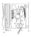
その転写領域から後方側(図示左方側)に向かって延びる搬送ベルト117は、上述したようにトナー像が転写された記録シートPを加熱定着装置118に送り込むように配置されている。加熱定着装置118内には、特に図2に示されているように、加熱体の一部を構成する定着フイルム118aが設けられているとともに、その定着フイルム118aの図示下面側に対して加圧ローラ118bが図示を省略したバネ等の適宜の付勢手段により圧接するように配置されていて、それら定着フイルム(加熱体)118aと加圧ローラ118bとの圧接部位に形成された定着ニップ領域内を被加熱体としての記録シート(記録材)Pが通過させられ、当該定着ニップ領域において付与される加熱・加圧作用によって前記記録シートP上の未定着トナー像に対する加熱定着処理が行われるようになっている。
The
図1に戻って、上述した加熱定着作用により永久画像を形成された記録シートPは、羽根板状をなす排出トレイ119上に排出されていく。また、定着後に感光体ドラム114の表面上に残された残留トナーは、クリーナ114bの残トナー掻き落とし作用によって除去される構成になされている。
Returning to FIG. 1, the recording sheet P on which a permanent image is formed by the above-described heat fixing action is discharged onto a
ここで、上述した加熱定着装置118内に設けられた定着フィルム118aは、特に図3に示されているように、剛性・耐熱性を有する加圧ステー118cに取り付けられた加熱支持部材を構成するフィルムガイド118dの外周表面に沿って環状に摺動可能となるように支持されており、そのフィルムガイド118dの図示下面側に形成された摺動表面の一部には、細長板状のセラミックヒータ118eの加熱表面が下方側に露出するようにして取り付けられている。
Here, the fixing
このセラミックヒータ118eは、前記加圧ローラ118bと定着フィルム118aとの圧接部位に形成された定着ニップ領域に対して定着プロセスに必要な熱を付与する加熱体を構成するものであって、当該セラミックヒータ118eの図示下面側の加熱表面に対して、前記定着フィルム118aの内周表面が摺動可能に密着された配置関係になされている。
The
なお、本実施形態における定着フイルム118aは、耐熱性、熱可塑性を有するポリイミド、ポリアミドイド、PEEK、PES、PPS、PFA、PTFE、FEP等の熱容量の小さい材質から形成されており、オフセット防止や記録材の分理性を確保するために当該定着フイルム118aの表層には、PFA、PTFE、FEP等の離型性の良好な耐熱樹脂が、混合又は単独で被覆されている。
Note that the fixing
また、前記加熱支持部材としてのフィルムガイド118dは、液晶ポリマー、フェノール樹脂、PPS、PEEK等により形成されていて、上述したようにセラミックヒータ118eを下端部に保持しているとともに、ニップ領域と反対方向への放熱を防ぐ断熱部材として構成されたものであり、上記定着フィルム118aが図2中の矢印方向に余裕を持って回れるような形状と大きさを備えている。
The
さらに、上述したセラミックヒータ118eとしては、例えば特開平4−44075号〜44083号公報、特開平4−204980号〜204984号公報等に開示された、いわゆるテンションレスタイプのものが採用されており、記録シートPの搬送方向(移動方向)に対して直交する長手方向に沿って細長状に延在する耐熱性・絶縁性・良熱伝導性を有するヒータ基板118fを備えているとともに、そのヒータ基板118fの長手方向(画像形成幅方向)に沿って抵抗発熱体118gが配置されている。そして、前記抵抗発熱体118gの長手方向両端部に配置された給電用電極(図示省略)から加熱用の電力が供給されて当該セラミックヒータ118eの加熱が行われるとともに、そのときの加熱温度が、前記ヒータ基板118fの直上部に配置されたサーミスタ(検温素子)118hにより検知されるようになっている。
Furthermore, as the above-described
一方、上述した加圧ローラ118bとしては、アルミニウム等の金属部材からなる芯金の外周側に、シリコンゴムやフッ素ゴム等の耐熱ゴム又はシリコンゴムの発泡体等からなる弾性層を介してプライマー層が形成されており、その表層にPFA、PTFE、FEP等のチューブからなる離型層が形成されたものが採用されている。上述したプライマー層は、導電性を有するように形成されており、乾燥紙などの高抵抗紙を通紙した場合に表面がマイナスに摩擦帯電する構成になされていることによって、トナーが摩擦電荷と反発して定着フィルム118a側に再度付着する静電オフセットの発生が防止される構成になされている。
On the other hand, as the
このような構成を有する加圧ローラ118bは、図示を省略したエンジンコントローラ(定着駆動制御手段)により駆動制御される適宜の定着モータを含む駆動手段により回転駆動される構成になされており、その加圧ローラ118bの回転駆動に追従して前記定着フィルム118aを環状に摺動させつつ移動させるとともに、定着ニップ領域内に導入された記録シート(被加熱材)Pを定着フィルム118aと密着させた状態に押圧させながら搬送(移動)させるように構成されている。このようにして記録シートPが定着ニップ領域内に搬送されることで、記録シートP上に担持された未定着のトナー像Tが、上述したセラミックヒータ118eからの熱と加圧ローラ118bによるニップ圧とで定着処理されるようになっている。
The
また、上述したように定着フィルム118aは、その内部側に配置されたセラミックヒータ(加熱体)118eの加熱表面及びフィルムガイド(加熱支持体)118dの摺動表面に対して摺擦しながら回転移動を行うため、それらセラミックヒータ118eの加熱表面及びフィルムガイド118dの摺動表面と、前記定着フィルム118aの内周表面との間の摩擦抵抗を小さく抑える必要がある。このため、それらセラミックヒータ118eの加熱表面及びフィルムガイド118dの摺動表面に対して定着フィルム118aが密着している部分には、当該定着フィルム118aの追従駆動性および摺動性を良好に維持するための耐熱性グリース等の潤滑剤を少量介在させてあり、それによって前記定着フィルム118aの円滑な回転移動を可能としている。
Further, as described above, the fixing
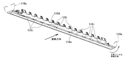
また、このように介在された耐熱性グリース等の潤滑剤に対応して、上記加熱支持部材としてのフィルムガイド118dの摺動表面(図3の下面)には、特に図4及び図5に示されているように、当該フィルムガイド118dの長手方向(画像形成幅方向)に上記潤滑剤を分散させるための流動案内溝118iが複数条にわたって形成されている。
Further, the sliding surface (the lower surface in FIG. 3) of the
それらの流動案内溝118iは、前記フィルムガイド(加熱支持部材)118dの摺動表面(図3の下面)のうち、前記定着フィルム118aの移動方向(図5の下方向)の下流側に位置する表面に形成されており、前記セラミックヒータ118eの下流側端縁から前記定着フィルム118aの移動方向に延出して、前記フィルムガイド118dの摺動表面の下流側端縁までの間を連通させるように配置されている。これらの各流動案内溝118iの底面部は、潤滑剤の流動性を向上させるように滑らかな曲線からなる凹形状、例えば略半円状の横断面形状をなすように形成されている。
These flow guide
また、上述した各流動案内溝118iは、前記定着フィルム118aの移動方向(図5の下方向)に対して適宜の傾斜角度をなして直線状に延在するように形成されており、それらの各流動案内溝118iにおける傾斜角度が、フィルムガイド(加熱支持部材)118dの長手方向(画像形成幅方向)に沿って連続的に変化するように設定されている。
Further, each of the
より具体的には、上述した複数条の流動案内溝118iのうちの最も中央側の領域に略対称的に配置された一対の中央流動案内溝118iの各々は、前記定着フィルム118aの移動方向(図5の下方向)に向かって、長手方向(画像形成幅方向)の外方側に開く傾斜角度をなすように設定されており、それによって中央領域に存在している潤滑剤を外方領域側に向かって流動させるように構成されている。また、それら一対の中央流動案内溝118iよりも外方側に配置された複数組の外方流動案内溝118iは、前記定着フィルム118aの移動方向(図5の下方向)に向かって、長手方向(画像形成幅方向)の内方側に閉じる傾斜角度をなすように設定されており、それによって中央領域から外方領域に移動する傾向がある潤滑剤を中央領域に向かって戻す方向に流動させる構成になされている。
More specifically, each of the pair of central
さらに、上述した外方流動案内溝118iの各々における傾斜角度は、互いに異なるように設定されていて、前記定着フィルム118aの移動方向(図5の下方向)と直交する長手方向(画像形成幅方向)の中央領域から外方領域に向かう方向において、上記各外方流動案内溝118iの傾斜角度が連続的に増大するように設定されている。そして、長手方向(画像形成幅方向)の最外位置に配置された流動案内溝118iは、前記セラミックヒータ118eの最外端位置から最大の急角度をなして前記フィルムガイド(加熱支持部材)118dの摺動表面(図3の下面)における最下流端(図5の最下端縁)まで延在している。以上のような構成を有する各流動案内溝118iは、全体として潤滑剤を長手方向(画像形成幅方向)に沿って略均一に分散させる機能を有している。
Further, the inclination angles in each of the outward
上記流動案内溝118iの具体的な実施例としては、幅5mm、深さ1mmのものが使用されているとともに、合計10本の各流動案内溝118iの傾斜角度が、中央側から順に、45°、60°、75°、105°にそれぞれ設定されている。
As a specific example of the
このような構成を有する本実施形態にかかる加熱装置によれば、加熱温度が比較的高く潤滑剤の流動性が良好になっている定着フィルム118aの移動方向の下流側に位置するフィルムガイド(加熱支持部材)118dの摺動表面に、潤滑剤を均一に分散させる流動案内溝118iが配置されていることから、フィルムガイド118d及び定着フィルム118aにおける長手方向の中央領域から両端領域にかけての全領域にわたって潤滑剤が良好に拡散されて均一分散されることとなり、定着フィルム118aの摺動性が長期にわたって良好に維持されるようになっている。
According to the heating apparatus according to the present embodiment having such a configuration, a film guide (heating) that is positioned on the downstream side in the moving direction of the fixing
実際に本実施形態を用いた場合におけるグリースの均一分散性を調べてみたところ、例えば図6及び図7に示されているような改善がみられた。すなわち、まず図6には、上述した定着フィルム118aの長手方向(画像形成幅方向)両端位置から8.5mmの位置にグリースを300mg塗布した状態で、A3サイズの紙の記録材を5000枚通紙したときの上記グリースの中央側への移動距離(縦軸)を調べた結果が示されているが、上述した本実施形態のようにフィルムガイド(加熱支持部材)118dの下流側の摺動表面に流動案内溝118iを設けた場合(下流側に溝の場合)には、約30mmの移動距離が観察されたのに対して、フィルムガイド118dの摺動表面の上流側に流動案内溝を設けた場合(上流側に溝の場合)には、移動距離が約25mmに低下し、さらに流動案内溝を全く設けない場合(溝無しの場合)の移動距離は約13mmまで低下した。
When the uniform dispersibility of the grease when actually using this embodiment was examined, for example, improvements as shown in FIGS. 6 and 7 were observed. That is, first, in FIG. 6, 5000 sheets of A3-size paper recording material are passed through 300 mg of grease applied at a position 8.5 mm from both longitudinal positions (image formation width direction) of the fixing
このことから、流動案内溝を設けない場合や、流動案内溝を上流側に配置した場合よりも、本実施形態のようにフィルムガイド(加熱支持部材)118dの下流側の摺動表面に流動案内溝118iを設けた場合の方が、潤滑剤を移動させる溝案内機能が向上させられることが解る。
Therefore, the flow guide is provided on the sliding surface on the downstream side of the film guide (heating support member) 118d as in this embodiment, compared to the case where the flow guide groove is not provided or the flow guide groove is disposed on the upstream side. It can be seen that the groove guiding function for moving the lubricant is improved when the
さらに、図7には、前述したセラミックヒータ(加熱体)118eの加熱表面に800mgのグリースを一様に塗布した状態で、A3サイズの紙記録材を5000枚通紙する場合における前記定着フィルム118aの長手方向一端部から漏れ出したグリースの量(縦軸)を調べた結果が示されているが、上述した本実施形態のようにフィルムガイド(加熱支持部材)118dの下流側の摺動表面に流動案内溝118iを設けた場合(下流側に溝の場合)には、約8mgの漏れ量しか観察されなかったのに対して、フィルムガイド118dの摺動表面の上流側に流動案内溝を設けた場合(上流側に溝の場合)には、グリース漏れ量は27mgに上昇し、さらに流動案内溝を全く設けない場合(溝無しの場合)のグリース漏れ量は53mgまで上昇した。
Further, FIG. 7 shows the fixing
このことから、流動案内溝を設けない場合や、流動案内溝を上流側に配置した場合よりも、本実施形態のようにフィルムガイド(加熱支持部材)118dの下流側の摺動表面に流動案内溝118iを設けた場合の方が、定着フィルム118aからの端部漏れを大幅に低減させられることが解る。
Therefore, the flow guide is provided on the sliding surface on the downstream side of the film guide (heating support member) 118d as in this embodiment, compared to the case where the flow guide groove is not provided or the flow guide groove is disposed on the upstream side. It can be seen that end leakage from the fixing
このとき、特に本実施形態では、フィルムガイド(加熱支持部材)118dの摺動表面に設けられた流動案内溝118iが、長手方向(画像形成幅方向)に複数条にわたって形成されているとともに、それらの各流動案内溝118iが定着フィルム118aの移動方向に対して傾斜する方向に延在しており、前記複数条の流動案内溝118iの各々における傾斜角度が互いに異ならされて長手方向(画像形成幅方向)において連続的に変化し、かつその流動案内溝118iの底面部が湾曲形状に形成されていることから、上述した潤滑剤の均一分散作用が確実に行われるようになっている。
At this time, particularly in the present embodiment, the
次に、図8及び図9に示されている第2の実施形態における各流動案内溝118jは、上述した第1の実施形態と同様にセラミックヒータ118eよりも下流側に位置する摺動表面に配置されていて、前記定着フィルム118aの移動方向(図9の下方向)と直交する長手方向(画像形成幅方向)において外方領域から中央領域側に向かう方向に傾斜して延在するように設けられているが、隣接する流動案内溝118jどうしの配置間隔が互いに異なるように設定されていて、その配置間隔が、長手方向(画像形成幅方向)の中央領域から外方領域に向かう方向において連続的に縮小するように設定されている。
Next, each flow guide
このように、隣接する流動案内溝118jどうしの配置間隔を外方領域において狭小とした理由は、外方領域に記録材が通過しない場合があるからであり、記録材が通過しない外方側領域では記録材によって熱が奪われなくなるために温度が上昇して潤滑剤の粘性が低下し、潤滑剤の流動性が大きくなることから、そのような外方領域により多くの流動案内溝118jを設けることによって、小サイズの記録材を連続通過させた場合においても流動案内溝118jの全体として潤滑剤を長手方向(画像形成幅方向)に略均一に分散させる機能を付与するように構成されている。
Thus, the reason why the arrangement interval between the adjacent
この場合における上記流動案内溝118jの具体的な実施例としては、幅5mm、深さ1mm、傾斜角度45°のものが使用されているとともに、合計10本の各流動案内溝118jの配置間隔は、最外端部から順に、0mm、11mm、26mm、65mm、104mm、226mm、275mm、304mm、319mm、330mm にそれぞれ設定されている。
As a specific example of the
このような第2の実施形態にかかる装置において、異音の発生を実際に調べてみたところ、次の[表1]に表されているような改善がみられた。すなわち、上述したフィルムガイド(加熱支持部材)118dの摺動表面にグリースを100mg一様に塗布した状態で葉書サイズの紙の記録材を5000枚通紙したときの異音の発生の有無を調べた結果が次の[表1]に示されている。

この表1から、上述した第2の実施形態のようにフィルムガイド118dの下流側の摺動表面に流動案内溝118jを設けた場合(下流側に溝の場合)には、1000枚の通紙時まで異音の発生がみられなかったのに対して、フィルムガイド118dの摺動表面の上流側に流動案内溝を設けた場合(上流側に溝の場合)には、768枚の通紙で異音が発生し、さらに流動案内溝を全く設けない場合(溝無しの場合)には400枚の通紙で異音の発生がみられた。
From Table 1, when the
このことから、流動案内溝を設けない場合や、流動案内溝を上流側に配置した場合よりも、本実施形態のようにフィルムガイド(加熱支持部材)118dの下流側の摺動表面に流動案内溝118jを設けた場合の方が、小サイズの記録材を通過させた場合においても潤滑剤が均一に分散されることによって異音の発生が低減されることが判明した。
Therefore, the flow guide is provided on the sliding surface on the downstream side of the film guide (heating support member) 118d as in this embodiment, compared to the case where the flow guide groove is not provided or the flow guide groove is disposed on the upstream side. It has been found that when the
以上、本発明者によってなされた発明の実施形態を具体的に説明したが、本発明は上述した実施形態に限定されるものではなく、その要旨を逸脱しない範囲で種々変形可能であることはいうまでもない。 The embodiments of the invention made by the present inventor have been specifically described above, but the present invention is not limited to the above-described embodiments, and various modifications can be made without departing from the scope of the invention. Not too long.
例えば、上述した各実施形態は、複写機に対して本発明を適用したものであるが、プリンタ等の他の画像形成装置に対しても本発明は同様に適用することができる。 For example, each of the embodiments described above applies the present invention to a copying machine, but the present invention can be similarly applied to other image forming apparatuses such as a printer.
以上述べたように本発明は、複写機やファクシミリなどの多種多様な画像形成装置に採用される加熱装置に対して広く適用することが可能なものである。 As described above, the present invention can be widely applied to heating devices employed in a wide variety of image forming apparatuses such as copying machines and facsimiles.
10 複写機(画像形成装置)
11 プリンタ部(プリンタ部)
12 画像読取装置
13 自動原稿供給装置(ADF)
P 記録シート
111 コントローラ
112 レーザビームスキャナ
113 一次帯電器
114 感光体ドラム
115 現像装置
116 シート供給カセット
117 搬送ベルト
118 加熱定着装置
119 排出トレイ
118a 定着フィルム(加熱体)
118b 加圧ローラ
118c 加圧ステー(加熱支持体)
118d フィルムガイド(加熱支持体)
118e セラミックヒータ(加熱体)
118f ヒータ基板
118g 抵抗発熱体
118h サーミスタ
118i 流動案内溝
118j 流動案内溝
10 Copying machine (image forming device)
11 Printer section (printer section)
12
118d Film guide (heating support)
118e Ceramic heater (heating body)
118f
Claims (6)
前記定着装置は、前記加熱支持部材の摺動表面及び前記加熱体の加熱表面と、前記フィルム状移動体との間に潤滑剤を有し、
前記加熱支持部材の摺動表面には、前記フィルム状移動体の移動方向における前記加熱体の下流側に、前記記録材の幅方向に複数条にわたって前記潤滑剤を案内する案内溝が設けられ、
前記複数条の案内溝の配置間隔は、前記記録材のサイズによって当該記録材が通過しない場合がある前記幅方向の外方領域が中央領域より狭く設定され、且つ
前記幅方向における両端の前記案内溝が、前記移動方向に沿って前記外方領域から中央領域に向かって傾斜していることを特徴とする画像形成装置。 The heating surface of the heating body arranged so as to expose a portion of the sliding surface of the heating support member via the film-like moving body is pressed against the recording material, moving the recording material with the film-like moving member In an image forming apparatus that includes a fixing device that performs heating while forming an image on the recording material,
The fixing device has a sliding surface and the heated surface of the heating body of the heating support member, a lubricant between the film-like moving member,
Wherein the sliding surface of the heating support member on the downstream side of the heating body in the moving direction of the film-like moving member, the guide grooves for guiding the lubricant over plural rows in the width direction of the recording material is provided,
The arrangement interval of the plurality of guide grooves is set such that the outer region in the width direction in which the recording material may not pass depending on the size of the recording material is narrower than the central region, and
The image forming apparatus , wherein the guide grooves at both ends in the width direction are inclined from the outer region toward the central region along the moving direction .
Priority Applications (3)
| Application Number | Priority Date | Filing Date | Title |
|---|---|---|---|
| JP2006331509A JP4937718B2 (en) | 2006-12-08 | 2006-12-08 | Image forming apparatus |
| US11/999,444 US7805102B2 (en) | 2006-12-08 | 2007-12-04 | Heating device and image formation apparatus |
| CN2007101989247A CN101221400B (en) | 2006-12-08 | 2007-12-07 | Fixation device for image foring device and image forming apparatus |
Applications Claiming Priority (1)
| Application Number | Priority Date | Filing Date | Title |
|---|---|---|---|
| JP2006331509A JP4937718B2 (en) | 2006-12-08 | 2006-12-08 | Image forming apparatus |
Publications (3)
| Publication Number | Publication Date |
|---|---|
| JP2008146964A JP2008146964A (en) | 2008-06-26 |
| JP2008146964A5 JP2008146964A5 (en) | 2010-01-28 |
| JP4937718B2 true JP4937718B2 (en) | 2012-05-23 |
Family
ID=39606895
Family Applications (1)
| Application Number | Title | Priority Date | Filing Date |
|---|---|---|---|
| JP2006331509A Expired - Fee Related JP4937718B2 (en) | 2006-12-08 | 2006-12-08 | Image forming apparatus |
Country Status (3)
| Country | Link |
|---|---|
| US (1) | US7805102B2 (en) |
| JP (1) | JP4937718B2 (en) |
| CN (1) | CN101221400B (en) |
Families Citing this family (29)
| Publication number | Priority date | Publication date | Assignee | Title |
|---|---|---|---|---|
| KR101155990B1 (en) * | 2007-07-13 | 2012-06-18 | 삼성전자주식회사 | Fixing apparatus and image forming apparatus having the same |
| JP5321905B2 (en) * | 2009-09-01 | 2013-10-23 | 株式会社リコー | Fixing apparatus and image forming apparatus |
| JP5359790B2 (en) | 2009-10-30 | 2013-12-04 | ブラザー工業株式会社 | Fixing device |
| EP2405309B1 (en) | 2009-10-30 | 2016-08-10 | Brother Kogyo Kabushiki Kaisha | Fusing device |
| JP5440097B2 (en) * | 2009-10-30 | 2014-03-12 | ブラザー工業株式会社 | Fixing device |
| JP2011095544A (en) * | 2009-10-30 | 2011-05-12 | Canon Inc | Image heating apparatus |
| US8306466B2 (en) * | 2009-12-07 | 2012-11-06 | Lexmark International, Inc. | Lubricant retention features on heater body of a fuser |
| JP5403264B2 (en) | 2010-01-13 | 2014-01-29 | 株式会社リコー | Fixing apparatus and image forming apparatus |
| JP5499821B2 (en) * | 2010-03-25 | 2014-05-21 | 富士ゼロックス株式会社 | Conveying device, fixing device, and image forming apparatus |
| US8534825B2 (en) | 2011-02-11 | 2013-09-17 | Xerox Corporation | Radiant heater for print media |
| JP5895417B2 (en) * | 2011-09-20 | 2016-03-30 | ブラザー工業株式会社 | Fixing device |
| JP6035668B2 (en) * | 2012-01-27 | 2016-11-30 | 株式会社リコー | Fixing apparatus and image forming apparatus |
| JP6032068B2 (en) * | 2013-03-08 | 2016-11-24 | 株式会社リコー | Fixing apparatus and image forming apparatus having the same |
| JP6043699B2 (en) * | 2013-09-13 | 2016-12-14 | 京セラドキュメントソリューションズ株式会社 | Fixing apparatus and image forming apparatus |
| JP6318521B2 (en) * | 2013-09-30 | 2018-05-09 | ブラザー工業株式会社 | Fixing device |
| US9703241B2 (en) | 2013-09-30 | 2017-07-11 | Brother Kogyo Kabushiki Kaisha | Fixing device provided with nip member capable of preventing outflow of lubricant |
| JP6111959B2 (en) | 2013-09-30 | 2017-04-12 | ブラザー工業株式会社 | Image forming apparatus and fixing device |
| JP2017083520A (en) * | 2015-10-23 | 2017-05-18 | 株式会社リコー | Fixing device and image forming apparatus |
| JP6686399B2 (en) * | 2015-12-04 | 2020-04-22 | ブラザー工業株式会社 | Fixing device and method of manufacturing fixing device |
| JP6735044B2 (en) * | 2016-07-05 | 2020-08-05 | 株式会社リコー | Fixing device and image forming apparatus |
| JP6778411B2 (en) | 2016-07-15 | 2020-11-04 | 株式会社リコー | Fixing device and image forming device |
| JP6684476B2 (en) * | 2018-03-30 | 2020-04-22 | ブラザー工業株式会社 | Fixing device |
| JP7119549B2 (en) * | 2018-05-09 | 2022-08-17 | 京セラドキュメントソリューションズ株式会社 | Fixing device and image forming device |
| JP7167645B2 (en) * | 2018-11-09 | 2022-11-09 | 京セラドキュメントソリューションズ株式会社 | Fixing device and image forming device |
| JP2020086404A (en) * | 2018-11-30 | 2020-06-04 | 株式会社リコー | Fixing device and image forming device |
| JP2020140097A (en) * | 2019-02-28 | 2020-09-03 | 京セラドキュメントソリューションズ株式会社 | Fixing device and image forming apparatus |
| JP2020140098A (en) * | 2019-02-28 | 2020-09-03 | 京セラドキュメントソリューションズ株式会社 | Fixing device and image forming apparatus |
| JP2020197701A (en) * | 2019-05-31 | 2020-12-10 | 京セラドキュメントソリューションズ株式会社 | Fixing device and image forming apparatus |
| JP7427431B2 (en) * | 2019-11-22 | 2024-02-05 | キヤノン株式会社 | Fixing device and image forming device |
Family Cites Families (5)
| Publication number | Priority date | Publication date | Assignee | Title |
|---|---|---|---|---|
| JP3254117B2 (en) * | 1995-10-04 | 2002-02-04 | キヤノン株式会社 | Image heating device |
| JP3634679B2 (en) * | 1999-07-30 | 2005-03-30 | キヤノン株式会社 | Heating device |
| JP2001203062A (en) * | 2000-01-20 | 2001-07-27 | Canon Inc | Heating device and image forming device |
| JP2004184814A (en) * | 2002-12-05 | 2004-07-02 | Canon Inc | Heating device |
| JP4534682B2 (en) * | 2004-09-13 | 2010-09-01 | 富士ゼロックス株式会社 | Fixing device and image forming apparatus |
-
2006
- 2006-12-08 JP JP2006331509A patent/JP4937718B2/en not_active Expired - Fee Related
-
2007
- 2007-12-04 US US11/999,444 patent/US7805102B2/en not_active Expired - Fee Related
- 2007-12-07 CN CN2007101989247A patent/CN101221400B/en not_active Expired - Fee Related
Also Published As
| Publication number | Publication date |
|---|---|
| US20080187372A1 (en) | 2008-08-07 |
| US7805102B2 (en) | 2010-09-28 |
| CN101221400A (en) | 2008-07-16 |
| JP2008146964A (en) | 2008-06-26 |
| CN101221400B (en) | 2010-09-08 |
Similar Documents
| Publication | Publication Date | Title |
|---|---|---|
| JP4937718B2 (en) | Image forming apparatus | |
| US9291967B2 (en) | Fixing device and image forming apparatus incorporating same | |
| JP5796711B2 (en) | Fixing apparatus and image forming apparatus | |
| JP5904325B2 (en) | Fixing apparatus and image forming apparatus | |
| US9063480B2 (en) | Fixing device, image forming device, and separating member | |
| JP2024019683A (en) | Fixing device and image forming device | |
| JP6464782B2 (en) | Fixing apparatus and image forming apparatus | |
| US20200004182A1 (en) | Heating device and image forming apparatus | |
| JP2013041183A (en) | Fixing device and image forming apparatus | |
| JP2006267234A (en) | Heating body and image heating apparatus | |
| JP6044856B2 (en) | Fixing apparatus and image forming apparatus | |
| US9110417B2 (en) | Fixing apparatus and image forming apparatus including the fixing apparatus | |
| JP2022001921A (en) | Image forming apparatus | |
| JP6826774B2 (en) | Fixing device and image forming device | |
| US20150030361A1 (en) | Fixing device and image forming apparatus | |
| JP2020149013A (en) | Heating device, fixing device, and image forming apparatus | |
| JP7338412B2 (en) | Fixing device and image forming device | |
| JP2019101372A (en) | Fixation device and image forming apparatus | |
| US20230324838A1 (en) | Heating device, nip forming device, and image forming apparatus | |
| JP7225925B2 (en) | Fixing device and image forming device | |
| US20230314987A1 (en) | Fixing device and image forming apparatus capable of suppressing deformation of fixing belt and excessive adhesion of lubricant | |
| US20230060287A1 (en) | Image heating device and image forming apparatus | |
| JP6977394B2 (en) | Curve correction device, fixing device and image forming device | |
| JP2008129060A (en) | Image heating and fixing device | |
| JP2020106673A (en) | Image heating device |
Legal Events
| Date | Code | Title | Description |
|---|---|---|---|
| A521 | Written amendment |
Free format text: JAPANESE INTERMEDIATE CODE: A523 Effective date: 20091208 |
|
| A621 | Written request for application examination |
Free format text: JAPANESE INTERMEDIATE CODE: A621 Effective date: 20091208 |
|
| A131 | Notification of reasons for refusal |
Free format text: JAPANESE INTERMEDIATE CODE: A131 Effective date: 20111129 |
|
| A521 | Written amendment |
Free format text: JAPANESE INTERMEDIATE CODE: A523 Effective date: 20120127 |
|
| TRDD | Decision of grant or rejection written | ||
| A01 | Written decision to grant a patent or to grant a registration (utility model) |
Free format text: JAPANESE INTERMEDIATE CODE: A01 Effective date: 20120221 |
|
| A01 | Written decision to grant a patent or to grant a registration (utility model) |
Free format text: JAPANESE INTERMEDIATE CODE: A01 |
|
| A61 | First payment of annual fees (during grant procedure) |
Free format text: JAPANESE INTERMEDIATE CODE: A61 Effective date: 20120222 |
|
| FPAY | Renewal fee payment (event date is renewal date of database) |
Free format text: PAYMENT UNTIL: 20150302 Year of fee payment: 3 |
|
| R150 | Certificate of patent or registration of utility model |
Ref document number: 4937718 Country of ref document: JP Free format text: JAPANESE INTERMEDIATE CODE: R150 Free format text: JAPANESE INTERMEDIATE CODE: R150 |
|
| R250 | Receipt of annual fees |
Free format text: JAPANESE INTERMEDIATE CODE: R250 |
|
| S531 | Written request for registration of change of domicile |
Free format text: JAPANESE INTERMEDIATE CODE: R313532 |
|
| R350 | Written notification of registration of transfer |
Free format text: JAPANESE INTERMEDIATE CODE: R350 |
|
| R250 | Receipt of annual fees |
Free format text: JAPANESE INTERMEDIATE CODE: R250 |
|
| R250 | Receipt of annual fees |
Free format text: JAPANESE INTERMEDIATE CODE: R250 |
|
| S533 | Written request for registration of change of name |
Free format text: JAPANESE INTERMEDIATE CODE: R313533 |
|
| R350 | Written notification of registration of transfer |
Free format text: JAPANESE INTERMEDIATE CODE: R350 |
|
| R250 | Receipt of annual fees |
Free format text: JAPANESE INTERMEDIATE CODE: R250 |
|
| R250 | Receipt of annual fees |
Free format text: JAPANESE INTERMEDIATE CODE: R250 |
|
| R250 | Receipt of annual fees |
Free format text: JAPANESE INTERMEDIATE CODE: R250 |
|
| LAPS | Cancellation because of no payment of annual fees |