JP4936542B2 - COMMUNICATION CONTROL DEVICE, COMMUNICATION CONTROL METHOD, AND COMPUTER PROGRAM - Google Patents
COMMUNICATION CONTROL DEVICE, COMMUNICATION CONTROL METHOD, AND COMPUTER PROGRAM Download PDFInfo
- Publication number
- JP4936542B2 JP4936542B2 JP2007211514A JP2007211514A JP4936542B2 JP 4936542 B2 JP4936542 B2 JP 4936542B2 JP 2007211514 A JP2007211514 A JP 2007211514A JP 2007211514 A JP2007211514 A JP 2007211514A JP 4936542 B2 JP4936542 B2 JP 4936542B2
- Authority
- JP
- Japan
- Prior art keywords
- packet
- moving image
- frame
- transmission interval
- image data
- Prior art date
- Legal status (The legal status is an assumption and is not a legal conclusion. Google has not performed a legal analysis and makes no representation as to the accuracy of the status listed.)
- Active
Links
Images


Classifications
-
- H—ELECTRICITY
- H04—ELECTRIC COMMUNICATION TECHNIQUE
- H04L—TRANSMISSION OF DIGITAL INFORMATION, e.g. TELEGRAPHIC COMMUNICATION
- H04L65/00—Network arrangements, protocols or services for supporting real-time applications in data packet communication
- H04L65/80—Responding to QoS
-
- H—ELECTRICITY
- H04—ELECTRIC COMMUNICATION TECHNIQUE
- H04L—TRANSMISSION OF DIGITAL INFORMATION, e.g. TELEGRAPHIC COMMUNICATION
- H04L47/00—Traffic control in data switching networks
- H04L47/10—Flow control; Congestion control
- H04L47/29—Flow control; Congestion control using a combination of thresholds
-
- H—ELECTRICITY
- H04—ELECTRIC COMMUNICATION TECHNIQUE
- H04L—TRANSMISSION OF DIGITAL INFORMATION, e.g. TELEGRAPHIC COMMUNICATION
- H04L47/00—Traffic control in data switching networks
- H04L47/50—Queue scheduling
-
- H—ELECTRICITY
- H04—ELECTRIC COMMUNICATION TECHNIQUE
- H04L—TRANSMISSION OF DIGITAL INFORMATION, e.g. TELEGRAPHIC COMMUNICATION
- H04L47/00—Traffic control in data switching networks
- H04L47/50—Queue scheduling
- H04L47/56—Queue scheduling implementing delay-aware scheduling
- H04L47/564—Attaching a deadline to packets, e.g. earliest due date first
-
- H—ELECTRICITY
- H04—ELECTRIC COMMUNICATION TECHNIQUE
- H04L—TRANSMISSION OF DIGITAL INFORMATION, e.g. TELEGRAPHIC COMMUNICATION
- H04L65/00—Network arrangements, protocols or services for supporting real-time applications in data packet communication
- H04L65/60—Network streaming of media packets
- H04L65/75—Media network packet handling
- H04L65/765—Media network packet handling intermediate
-
- H—ELECTRICITY
- H04—ELECTRIC COMMUNICATION TECHNIQUE
- H04N—PICTORIAL COMMUNICATION, e.g. TELEVISION
- H04N21/00—Selective content distribution, e.g. interactive television or video on demand [VOD]
- H04N21/20—Servers specifically adapted for the distribution of content, e.g. VOD servers; Operations thereof
- H04N21/23—Processing of content or additional data; Elementary server operations; Server middleware
- H04N21/238—Interfacing the downstream path of the transmission network, e.g. adapting the transmission rate of a video stream to network bandwidth; Processing of multiplex streams
- H04N21/23805—Controlling the feeding rate to the network, e.g. by controlling the video pump
-
- H—ELECTRICITY
- H04—ELECTRIC COMMUNICATION TECHNIQUE
- H04L—TRANSMISSION OF DIGITAL INFORMATION, e.g. TELEGRAPHIC COMMUNICATION
- H04L65/00—Network arrangements, protocols or services for supporting real-time applications in data packet communication
- H04L65/60—Network streaming of media packets
- H04L65/65—Network streaming protocols, e.g. real-time transport protocol [RTP] or real-time control protocol [RTCP]
Description
本発明は、通信制御装置、通信制御方法、及びコンピュータプログラムに関し、特に、パケット通信を行うために用いて好適なものである。 The present invention relates to a communication control device, a communication control method, and a computer program, and is particularly suitable for use in performing packet communication.
近年、通信システムの発達により、比較的大きなデータ通信帯域が必要となる動画像データを、インターネット等の通信回線を通して受信して視聴者に視聴させることが一般に行われるようになってきている。
このような動画像データの送信、特にライブ映像等のリアルタイム性を必要とする動画像データの長時間にわたる送信のために、RTPと呼ばれるプロトコルを用いるのが一般的となっている。RTPは、IETFによりRFC1889及びRFC1890として定義された、音声や動画像等をリアルタイムでデータ転送するためのプロトコルである。尚、RTPは、A Transport Protocol for Real-Time Applicationsの略である。
本明細書では、例えばRTPのようなプロトコルを用いて送信する音声や動画像等のデータを、必要に応じて、ストリーム或いはストリームデータと呼ぶことにする。
In recent years, with the development of communication systems, moving image data that requires a relatively large data communication band is generally received through a communication line such as the Internet and viewed by a viewer.
In order to transmit such moving image data, particularly to transmit moving image data that requires real-time performance such as live video over a long period of time, it is common to use a protocol called RTP. RTP is a protocol for transferring data such as voice and moving images in real time, defined as RFC1889 and RFC1890 by the IETF. RTP is an abbreviation for A Transport Protocol for Real-Time Applications.
In this specification, for example, data such as audio and moving images transmitted using a protocol such as RTP is referred to as a stream or stream data as necessary.
一般的に、RTPによる通信に代表されるリアルタイム通信においては、必ずしもデータの信頼性が高いとは言えないが、比較的単純に通信速度の改善が期待できるUDP/IP等の低層プロトコルが利用されている。RTPにおいては、これを強く想定したものとなっている。
このようなUDP/IP等のプロトコルを用いた通信は、リアルタイム性には優れているものの、その性質上、パケットロス等のエラーが発生しやすいという問題がある。もし、エラーが発生すれば、動画像の一部が欠落するといった現象が発生する可能性が高い。このため、様々な工夫がなされている。例えば、圧縮符号化された動画像データに対し、符号化時点でエラーの波及する範囲を限定する仕組みを組み込んだり、一度発生したエラーに対して再生表示する際の動画像の欠落を目立たなくしたりするといったことが実際に行われている。
また、通信の側面からは、より信頼性の高い通信回線が提案され、特定条件下では、エラー率はかなり低いものとなってきている。
In general, in real-time communication represented by RTP communication, data reliability is not necessarily high, but a lower layer protocol such as UDP / IP that can be expected to improve communication speed relatively simply is used. ing. This is strongly assumed in RTP.
Although communication using such a protocol such as UDP / IP is excellent in real-time property, there is a problem that an error such as packet loss is likely to occur due to its nature. If an error occurs, there is a high possibility that a part of the moving image will be lost. For this reason, various ideas have been made. For example, for compression-coded moving image data, a mechanism for limiting the range of error propagation at the time of encoding may be incorporated, or missing moving images may be made inconspicuous when playing back and displaying an error once generated Things are actually happening.
Further, from the communication aspect, a more reliable communication line has been proposed, and the error rate has become considerably low under specific conditions.
一方、エラーが発生する状況においては、そのエラーを抑制させる事も重要な課題となっている。
従来、パケットロス等のエラーの発生を抑制させる技術として、次のような技術が提案されている(特許文献1を参照)。すなわち、パケットの送信タイミングを遅延させることで、非常に短い送信間隔でパケットが送出されることを抑制し、ネットワーク経路のルーター等におけるバッファのデータが溢れることによるデータ損失を少なくする技術が提案されている。
On the other hand, in the situation where an error occurs, it is also an important issue to suppress the error.
Conventionally, the following technique has been proposed as a technique for suppressing the occurrence of errors such as packet loss (see Patent Document 1). In other words, a technique has been proposed in which packet transmission timing is delayed to prevent packets from being sent out at very short transmission intervals, and to reduce data loss due to overflow of buffer data in routers and the like of network routes. ing.
しかしながら、所定の時間空けて(所定の送信間隔で)パケットを送信する場合、一定時間の送信レート、或いは一定時間に送信するパケットの数によっては、ストリームを構成する動画像データのフレームレート内での送信が行えない場合がある。前述した従来の技術では、このような場合等に対する考慮がなされておらず、伝送エラーが生じ得るという問題点があった。
本発明は、このような問題点に鑑みてなされたものであり、動画像データの伝送エラーを低減することを目的とする。
However, when packets are transmitted with a predetermined time interval (at a predetermined transmission interval), depending on the transmission rate of a certain time or the number of packets transmitted in a certain time, within the frame rate of moving image data constituting the stream May not be sent. In the conventional technique described above, such a case is not considered, and there is a problem that a transmission error may occur.
The present invention has been made in view of such problems, and an object thereof is to reduce transmission errors of moving image data.
本発明の通信制御装置は、受信装置へ動画データのパケットを送信する通信制御装置であって、前記受信装置へ送信する動画データを取得する取得手段と、前記動画データを再生中の前記受信装置における前記動画データのパケットの到着時間を遅延させられる遅延時間情報を算出する算出手段と、前記算出された遅延時間情報に応じて、所定の圧縮形式のフレームのパケットの送信間隔が、当該フレームのパケット数と前記動画データのフレームレートとに基づく送信間隔よりも長くなるように、前記動画データのパケットの送信間隔を決定する決定手段と、前記決定手段により決定された送信間隔に応じたタイミングで、前記動画データのパケットを送信する送信手段とを備えることを特徴とする。 The communication control device according to the present invention is a communication control device that transmits a packet of moving image data to a receiving device, an acquisition unit that acquires moving image data to be transmitted to the receiving device, and the receiving device that is reproducing the moving image data Calculating means for calculating delay time information capable of delaying the arrival time of the packet of the moving image data in accordance with the calculated delay time information, the packet transmission interval of a predetermined compression format frame A determination unit that determines a transmission interval of packets of the moving image data so as to be longer than a transmission interval based on the number of packets and a frame rate of the moving image data; and a timing according to the transmission interval determined by the determination unit And transmitting means for transmitting the moving image data packet.
本発明の通信制御方法は、受信装置へ動画データのパケットを送信する通信制御装置が行う通信制御方法であって、前記受信装置へ送信する動画データを取得する取得ステップと、前記動画データを再生中の前記受信装置における前記動画データのパケットの到着時間を遅延させられる遅延時間情報を算出する算出ステップと、前記算出された遅延時間情報に応じて、所定の圧縮形式のフレームのパケットの送信間隔が、当該フレームのパケット数と前記動画データのフレームレートとに基づく送信間隔よりも長くなるように、前記動画データのパケットの送信間隔を決定する決定ステップと、前記決定ステップにより決定された送信間隔に応じたタイミングで、前記動画データのパケットを送信する送信ステップとを備えることを特徴とする。 The communication control method of the present invention is a communication control method performed by a communication control device that transmits a packet of moving image data to a receiving device, an acquisition step of acquiring moving image data to be transmitted to the receiving device, and reproduction of the moving image data A calculation step of calculating delay time information for delaying an arrival time of the video data packet in the receiving device, and a packet transmission interval of a frame in a predetermined compression format according to the calculated delay time information Determining a transmission interval of the moving image data packets such that the transmission interval is longer than a transmission interval based on the number of packets of the frame and the frame rate of the moving image data, and the transmission interval determined by the determining step A transmission step of transmitting the moving image data packet at a timing according to .
本発明のコンピュータプログラムは、受信装置へ動画データのパケットを送信するコンピュータに、前記受信装置へ送信する動画データを取得する取得ステップと、前記動画データを再生中の前記受信装置における前記動画データのパケットの到着時間を遅延させられる遅延時間情報を算出する算出ステップと、前記算出された遅延時間情報に応じて、所定の圧縮形式のフレームのパケットの送信間隔が、当該フレームのパケット数と前記動画データのフレームレートとに基づく送信間隔よりも長くなるように、前記動画データのパケットの送信間隔を決定する決定ステップと、前記決定ステップにより決定された送信間隔に応じたタイミングで、前記動画データのパケット送信する送信ステップとを実行させることを特徴とする。 The computer program of the present invention includes: an acquisition step of acquiring moving image data to be transmitted to the receiving device to a computer that transmits a packet of moving image data to the receiving device; and the moving image data in the receiving device that is reproducing the moving image data. A calculation step of calculating delay time information capable of delaying the arrival time of the packet, and in accordance with the calculated delay time information, a packet transmission interval of a frame in a predetermined compression format includes the number of packets of the frame and the moving image A determination step for determining a transmission interval of packets of the moving image data so as to be longer than a transmission interval based on a frame rate of the data, and a timing according to the transmission interval determined by the determination step; A transmission step of transmitting a packet is executed.
本発明によれば、送信するデータの特性や、通信の特性に適したタイミングでパケットを送信することができ、パケットロス等の伝送エラーを低減することができる。 According to the present invention, packets can be transmitted at a timing suitable for the characteristics of data to be transmitted and the characteristics of communication, and transmission errors such as packet loss can be reduced.
<第1の実施形態>
以下に、図面を参照しながら、本発明の第1の実施形態について説明する。尚、以下の実施形態では、通信制御装置の一例である送信装置が、通信機能を備えたネットワークカメラとしての機能を有する場合を例に挙げて説明を行う。
図1は、送信装置のシステム構成の一例を示すブロック図である。
図1において、ストリーム取得部101は、撮像部を備え、動画像データ及び音声データを含むストリームデータを送信用のデータとして取得する。尚、ストリームデータは、必ずしもこのようなものでなくてもよい。映像データ、音声データ、及びグラフィックデータの少なくとも何れか1つを含むマルチメディアデータであれば、どのようなストリームデータであってもよい。
<First Embodiment>
Hereinafter, a first embodiment of the present invention will be described with reference to the drawings. In the following embodiments, a case where a transmission device which is an example of a communication control device has a function as a network camera having a communication function will be described as an example.
FIG. 1 is a block diagram illustrating an example of a system configuration of a transmission apparatus.
In FIG. 1, a
ストリーム取得部101で取得されたストリームデータは、ストリーム符号化部102において符号化される。符号化されたストリームデータは、パケット化部103において、通信に適したサイズにパケット化される。パケット化されたストリームデータは、一旦、バッファメモリ108に保管される。尚、以下の説明では、パケット化されたストリームデータを、必要に応じてパケットデータ又はパケットと称する。
The stream data acquired by the
ストリーム特性情報取得部106と通信特性情報取得部107は、夫々ストリーム特性情報と通信特性情報を取得する。本実施形態では、ストリーム特性情報取得部106は、ストリーム符号化部102で符号化されたストリームデータの特性を示すストリーム特性情報として、ビットレートと、フレームレートと、ストリームデータを構成する各フレームのサイズ等を取得する。
The stream characteristic
ストリーム特性情報は、ストリームデータの特性を表すものであれば、どのような情報であっても、ストリーム特性情報として採用することができる。例えば、ストリーム特性情報として、ストリームデータ全体のサイズ、ストリームデータ全体の復号化時間又は再生時間、及び所定の処理時間毎のストリームデータのサイズ等を採用することもできる。ここで、所定の処理時間としては、例えば、フレームレートに基づく時間が挙げられ、より具体的には、ストリームデータにおける1フレーム当たりの復号化時間又は再生時間(フレームレートの逆数)が挙げられる。
また、ストリーム特性情報として、所定の処理単位での復号化時間又は再生時間、及び所定の処理単位毎のストリームデータのサイズを採用することができる。更に、所定の処理単位内で最も大きなフレームのサイズ、及び所定の処理単位に含まれるフレームにおける1フレーム当たりの復号化時間又は再生時間をストリーム特性情報として採用することもできる。所定の処理単位には、ストリームデータを構成する1つ以上のフレームが含まれており、例えば、後述するGOPやGOVを所定の処理単位として採用することができる。
以上のように本実施形態では、ストリーム特性情報によりデータ特性情報が実現される。
As long as the stream characteristic information represents the characteristic of the stream data, any information can be adopted as the stream characteristic information. For example, as the stream characteristic information, the size of the entire stream data, the decoding time or reproduction time of the entire stream data, the size of the stream data for each predetermined processing time, and the like may be employed. Here, examples of the predetermined processing time include a time based on the frame rate, and more specifically, a decoding time or a reproduction time per frame (reciprocal of the frame rate) in the stream data.
As the stream characteristic information, a decoding time or a reproduction time in a predetermined processing unit and a stream data size for each predetermined processing unit can be adopted. Furthermore, the size of the largest frame within a predetermined processing unit and the decoding time or reproduction time per frame in the frames included in the predetermined processing unit can be adopted as the stream characteristic information. The predetermined processing unit includes one or more frames constituting stream data. For example, a GOP or GOV described later can be adopted as the predetermined processing unit.
As described above, in this embodiment, data characteristic information is realized by stream characteristic information.
また、通信特性情報取得部107は、ストリームデータ以外の特性であって、ストリームデータを送信する際の通信の特性を示す通信特性情報として、次のような情報を取得する。即ち、通信経路の有効帯域や、送信装置のシステムを制御するクロックの精度(パケットの送信処理を行うにあたって参照されるクロックの精度)等を取得する。通信特性情報は、ストリームデータを送受信する際の通信の特性を表すものであれば、どのような情報であっても、通信特性情報として採用することができる。例えば、通信特性情報として、パケットのサイズ、通信に供することの出来る通信速度、ストリームデータを復号化又は再生する処理を行うにあたって許容される遅延時間を採用することができる。更に、ストリームデータを復号化又は再生する処理を行うためのバッファのサイズ、及び通信経路で発生するエラーの発生率を通信特性情報として採用することができる。尚、パケットのサイズは、ストリーム特性情報として扱うこともできる。
Further, the communication characteristic
次に、スケジューリング部104は、ストリーム特性情報と通信特性情報とに基づいて、バッファメモリ108に一旦保管されたパケットデータの送信タイミングを制御する。送信部105は、スケジューリング部104で制御された送信タイミングの情報に従って、バッファメモリ108からパケットデータを読み出し、ネットワークへ送信する。
Next, the
システムコントローラ110は、ストリームデータの取得からパケットを送信するまでの一連の処理において、図1に示したシステムの統括的な制御を行う。メインメモリ109は、システムコントローラ110が制御を行う上で必要に応じて記憶領域を提供する。
The
図2は、ストリームデータを取得してからパケットデータを送信するまでの送信装置の構成の一例を、データの流れと共に示すブロック図である。
前述したように、ストリーム符号化部102は、ストリーム取得部101から入力されたストリームデータ210を符号化する。パケット化部103は、符号化されたストリームデータを、通信に適したサイズに分割し、分割したストリームデータの各々に適切なヘッダ情報を付加してパケット211を生成する。
パケット211は、バッファメモリ108へ格納され、格納されたパケット211の格納情報212は、システムコントローラ110へ伝えられる。尚、図2において、バッファメモリ108は、送信バッファとして機能し、システムコントローラ110は、バッファ管理部として機能する。
FIG. 2 is a block diagram showing an example of the configuration of a transmission apparatus from the acquisition of stream data to the transmission of packet data, together with the data flow.
As described above, the
The
スケジューリング部104は、ストリーム特性情報取得部106からストリーム特性情報215を入力し、通信特性情報取得部107から通信特性情報213を入力する。尚、スケジューリング部104は、ストリーム特性情報215の一部を、システムコントローラ110で保持されている「パケット211の格納情報212」に基づいて取得する。
スケジューリング部104は、入力されたストリーム特性情報215及び通信特性情報213に基づいてパケット211の送信タイミングが計算される。そして、その送信タイミングの計算結果が、送信タイミング情報として送信部105に送られる。
The
The
送信部105は、送信タイミング情報に基づいて、バッファメモリ108から、システムコントローラ110を介して、パケット(パケット化されたストリームデータ)211を読み出す。そして、送信部105は、有線又は無線のネットワークへ繋がる経路214へパケット211を送信する。
The
次に、スケジューリング部104により、パケット211の送信タイミングを調整する場合の動作の一例について説明する。
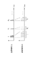
図3は、スケジューリング部104において計算された送信タイミング情報に基づいて送信タイミングの制御を行った場合のパケット送信間隔の変化の概要の一例を示す図である。
図3において、I、P1、P2、・・・は、符号化された動画像データのフレームのタイプを示している。ここで、動画像データをパケット化して送受信を行う場合に一般的な、動画像データの圧縮符号化処理の内容について説明する。
圧縮符号化処理の代表的な方式として、MPEG−2(ISO/IEC 13818)やMPEG−4(ISO/IEC 14496)が挙げられる。これらの符号化方式に共通する圧縮形式(動画像データを構成する各フレームを圧縮する圧縮形式)として、主要な3種類の圧縮形式について説明する。
Next, an example of an operation when the
FIG. 3 is a diagram illustrating an example of an outline of a change in packet transmission interval when transmission timing is controlled based on transmission timing information calculated in the
3, I, P1, P2,... Indicate the types of frames of encoded moving image data. Here, the contents of compression encoding processing of moving image data, which is common when moving image data is packetized and transmitted / received, will be described.
MPEG-2 (ISO / IEC 13818) and MPEG-4 (ISO / IEC 14496) are typical examples of compression encoding processing. Three main types of compression formats will be described as compression formats common to these encoding methods (compression formats for compressing each frame constituting moving image data).
1つ目の圧縮形式は、1つのフレーム内の情報のみでマクロブロック処理等を行って圧縮符号化処理を行うものであり、この圧縮形式で圧縮されたフレームはIフレーム(Intra-coded Frame)と呼ばれる。
2つ目の圧縮形式は、時間軸上で前方のフレームを参照しながら、動き補償予測、マクロブロック処理等を行うものであり、前方のフレームに依存した圧縮形式である。この方式で圧縮されたフレームはPフレーム(Predicted Frame)と呼ばれる。
3つ目の圧縮形式は、Pフレームと同様に、時間軸上で隣り合ったフレームを参照しながら圧縮符号化を行うものである。ただし、Pフレームは、前方のフレームのみを参照して圧縮されたものであるのに対し、この圧縮形式では、時間軸上で前後に隣り合うフレームを参照しながら動き補償予測、マクロブロック処理等を行う。この方式で圧縮されたフレームは、Bフレーム(Bi-directional Predicted Frame)と呼ばれる。
The first compression format performs compression coding processing by performing macroblock processing or the like using only information in one frame, and a frame compressed in this compression format is an I-frame (Intra-coded Frame). Called.
The second compression format performs motion compensation prediction, macroblock processing, and the like while referring to the front frame on the time axis, and is a compression format depending on the front frame. A frame compressed by this method is called a P frame (Predicted Frame).
The third compression format performs compression encoding while referring to adjacent frames on the time axis in the same manner as the P frame. However, while the P frame is compressed with reference to only the front frame, in this compression format, motion compensation prediction, macroblock processing, and the like are performed while referring to adjacent frames on the time axis. I do. A frame compressed by this method is called a B-frame (Bi-directional Predicted Frame).
また、いくつかの符号化済みのフレームの集合は、符号化形式がMPEG−2の場合はGOP(Group Of Picture)と呼ばれる。また、MPEG−4の場合はGOV(Group Of Video Object Plane)と呼ばれる。通常、符号化済みの動画データはGOP或いはGOVの組み合わせのフレームが連続して連なったものとなっている。以下の説明では、符号化済みのフレームの集合をGOPと総称する。また、以上のような画像のフレーム(Frame)はピクチャ(Picture)とも呼ばれるが、ここではフレーム(Frame)と呼ぶことにする。 A set of several encoded frames is called GOP (Group Of Picture) when the encoding format is MPEG-2. In the case of MPEG-4, it is called GOV (Group Of Video Object Plane). In general, encoded moving image data is a series of frames of GOP or GOV combinations. In the following description, a set of encoded frames is collectively referred to as GOP. Also, the frame of an image as described above is also called a picture, but here it is called a frame.
図3に示すI、Pは各々Iフレーム、Pフレームを表しており、Pの添え字の数字は同じ符号化形式のフレームを識別するためのものである。図3の『送信制御なし』のところに示しているパケット送信間隔は、パケット送信間隔の制御を行っていない場合のパケット211の送信間隔である。一方、『送信制御あり』のところに示している送信間隔は、パケット送信間隔の制御を行っている場合のパケット211の送信間隔である。ここでは、Iフレーム及びPフレームの各々のフレームをパケット化したデータの送信間隔を広げることで、パケット送信間隔の狭い部分と広い部分との差を少なくしている様子を示している。尚、Bフレームについては、本実施形態の構成の説明を簡単にするために、詳細な説明を省略する。
I and P shown in FIG. 3 represent an I frame and a P frame, respectively, and the subscript numbers of P are for identifying frames of the same encoding format. The packet transmission interval shown in “No transmission control” in FIG. 3 is the transmission interval of the
次に、スケジューリング部104における送信タイミングの計算方法の一例について説明する。
前述したように、スケジューリング部104は、ストリーム特性情報215をストリーム特性情報取得部106及びシステムコントローラ110から取得し、通信特性情報213を通信特性情報取得部107から取得する。
スケジューリング部104における送信タイミングの計算処理で必要となるストリーム特性情報215は、パケット211の送信間隔の制御の方法によって異なり、前述したもの中から、制御の方法に応じたものが選択される。本実施形態では、より一般的な2つの方法について説明する。即ち、フレームレートを守った上で、パケット211の送信間隔をフレーム単位で制御する方法と、GOPに含まれるフレームの送信間隔をGOP単位で制御する方法との2つの方法について、図4を用いて説明する。図4は、スケジューリング部104において計算された送信タイミング情報に基づいて送信タイミングの制御を行った場合のパケットの送信間隔の変化の概要の一例を示す図である。
Next, an example of a transmission timing calculation method in the
As described above, the
The stream
図4(a)の『制御なし』は、送信間隔の制御を行っていない場合のパケットの送信間隔の一例を示している。図4(b)の『制御1』は、フレームレートを守ってフレーム単位で送信間隔を制御している場合のパケットの送信間隔の一例を示している。図4(c)の『制御2』は、GOP単位で送信間隔を制御している場合のパケットの送信間隔の一例を示している。図4(a)〜図4(c)は、夫々の場合におけるパケットの送信時刻の違いを示している。 “No control” in FIG. 4A shows an example of a packet transmission interval when the transmission interval is not controlled. “Control 1” in FIG. 4B shows an example of a packet transmission interval when the transmission interval is controlled in units of frames while keeping the frame rate. “Control 2” in FIG. 4C shows an example of the packet transmission interval when the transmission interval is controlled in GOP units. FIGS. 4A to 4C show the difference in packet transmission time in each case.
図4(a)に示す例では、特にパケットの送信間隔の制御を行っていない。このため、1つのフレームをパケット化したパケット毎の送信間隔は処理クロックの精度等に依存する。よって、一般に、図4(a)のように、パケットの送信間隔が狭くなる。 In the example shown in FIG. 4A, the packet transmission interval is not particularly controlled. For this reason, the transmission interval for each packet obtained by packetizing one frame depends on the accuracy of the processing clock. Therefore, in general, the packet transmission interval is narrowed as shown in FIG.
図4(b)に示す例では、フレームレートを守った上で、個々のフレームを構成するパケット211の送信間隔を広げることで、その送信間隔の局所的な変動を軽減している。このような制御を行う上で最低限必要となるストリーム特性情報215には、フレームのサイズとフレームレートとが含まれる。個々のフレームをパケット化するには、更にパケット211のサイズの情報(パケットサイズ情報)が必要となるが、これは予め決められた固定値であっても、パケットを生成するタイミングで与えられる可変値であっても良い。
In the example shown in FIG. 4B, the local fluctuation of the transmission interval is reduced by widening the transmission interval of the
図2を用いて説明すると、スケジューリング部104は、送信するフレームがパケット化部103でパケット化された際にシステムコントローラ110へ送られるパケットサイズ情報とフレームサイズの情報とをシステムコントローラ110から取得する。また、スケジューリング部104は、フレームレートの情報を、ストリーム特性情報取得部106からストリーム特性情報215として取得する。
ここで、パケットサイズをPac_Size、フレームサイズをFrame_Size、フレームレートをFrame_Rate、とすると、図4(b)に示す「パケット211の送信間隔ΔT(B)は、以下の(1)式で表される。
ΔT(B)=1/Frame_Rate/(Frame_Size/Pac_Size) ・・・(1)
尚、ここでのパケットサイズPac_Sizeとは、パケットのヘッダ部分を除いたペイロード部分のサイズを意図している。
Referring to FIG. 2, the
Assuming that the packet size is Pac_Size, the frame size is Frame_Size, and the frame rate is Frame_Rate, “the transmission interval ΔT (B) of the
ΔT (B) = 1 / Frame_Rate / (Frame_Size / Pac_Size) (1)
The packet size Pac_Size here is intended to be the size of the payload portion excluding the header portion of the packet.
次に、図4(c)に示す例について説明する。図4(c)では、『I,P1,P2,P3,・・・,P14』というように、先頭がIフレームで残りの14個がPフレームで構成されているGOP単位でパケット211の送信間隔を制御した場合の一例を示している。GOPを構成する全てのフレームのパケット211を、1GOP分の時間内に均等な間隔で送信するような制御を意図している。つまり、GOP内における個々のフレームレベルでのフレームレートは必ずしも守られない。即ち、図4(c)に示す例の場合、先頭のIフレームのパケット211を、次のPフレームP1やその次のPフレームP2の本来の送信時間まで使用して送信している。このため、PフレームP1の送信開始時刻は時刻t1から時刻t1´へとずれ込み、その差分ΔT1の遅延が発生する。
Next, an example shown in FIG. 4C will be described. Figure 4 (c), the "I, P 1, P 2, P 3, · · ·, P 14" so on, top in GOP units remaining fourteen are constituted by P-frame in I-frame An example in which the transmission interval of the
ところで、図4(c)に示す前記GOPの構成例では、通常、先頭のIフレームのサイズが最も大きい。このことから、パケット211のサイズが略一定だとすると、同じGOPを構成する他のPフレームに比較して、送信するパケット数はIフレームが最も多くなる。よって、先頭のIフレームのパケット211の送信が完了した時点のフレームレートに対する遅延時間を、続くPフレームP2、P3・・・の送信時間内で徐々に少なくするようにパケット211の送信間隔を制御する。本実施形態では、このようにすることで、最後のPフレームP12の送信完了時点ではフレームレートに対する遅延が無くなっているようにパケット211の送信間隔を制御する。例えば、図4(c)におけるフレームP3でのフレームレートに対する遅延時間ΔT3は、フレームP1における遅延時間ΔT1よりも小さくなっている。
By the way, in the configuration example of the GOP shown in FIG. 4C, the size of the leading I frame is usually the largest. Therefore, if the size of the
即ち、図4(c)に示すようにGOP単位でパケット211の送信間隔を制御する場合の最も簡単な方法1つは、1つのGOPにおいて、各フレームをパケット化したものを均等な送信間隔で送信する方法である。このような方法でパケット211の送信間隔を制御する場合、スケジューリング部104は、ストリーム特性情報215として、1GOPの再生時間Tgopと、GOP全体の発生符合量Sgopと、ペイロードサイズPgopとを取得する。そして、スケジューリング部104は、パケット211の送信間隔ΔT(C)を、次の(2)式を用いて求めることができる。
ΔT(C)=Tgop/(Sgop/Pgop) ・・・(2)
このパケット送信間隔ΔT(C)は、前述したパケット211の送信制御の内容からも明らかなように、送信対象のGOPを1GOP分の時間内に送信できる時間の上限値となる。
以上のように、図4(c)に示すパケットの送信間隔の少なくとも一部が、フレームレートを守ってパケットを送信する場合のパケットの送信間隔(図4(b)に示す送信間隔)よりも長くなるように、図4(c)に示すパケットの送信間隔は設定される。
That is, as shown in FIG. 4 (c), one of the simplest methods for controlling the transmission interval of
ΔT (C) = Tgop / (Sgop / Pgop) (2)
This packet transmission interval ΔT (C) is an upper limit value of the time during which the transmission target GOP can be transmitted within the time of 1 GOP, as is apparent from the content of the transmission control of the
As described above, at least a part of the packet transmission interval shown in FIG. 4C is more than the packet transmission interval (transmission interval shown in FIG. 4B) in the case of transmitting the packet while keeping the frame rate. The packet transmission interval shown in FIG. 4C is set so as to be longer.
次に、GOP単位でパケット211の送信間隔の制御を行う前述した2つの方法のうち、より実際の処理形態に近い方法の一例について、図5を用いて説明する。
図5は、ライブ映像の動画像データを送信する際に、GOP単位でパケット211の送信間隔を制御(計算)する方法の一例を説明するフローチャートである。
まず、ステップS501において、スケジューリング部104は、以下の情報を通信特性情報213、ストリーム特性情報215として、ストリーム特性情報取得部106、通信特性情報取得部107から取得する。即ち、スケジューリング部104は、ライブ映像が受信装置で表示されるまでの許容遅延時間と、送信装置と受信装置と間のRTT(Round Trip Time)と、送信装置及び受信装置の内部処理時間(符号化・復号化処理時間)とを取得する。ここでの内部処理時間には、符号化及び復号化に関する処理全般において使用する処理バッファに依存する遅延時間を含むものとする。
Next, an example of a method closer to the actual processing mode among the above-described two methods for controlling the transmission interval of the
FIG. 5 is a flowchart for explaining an example of a method for controlling (calculating) the transmission interval of the
First, in step S <b> 501, the
次に、ステップS502において、スケジューリング部104は、次の(3)式を用いて、最大遅延時間を算出する。
最大遅延時間=許容遅延時間−内部処理時間−RTT/2 ・・・(3)
ここで算出する最大遅延時間とは、次のような時間を意図している。即ち、パケット211の送信開始時刻を起点とする動画像データのフレームレートに対し、実際に各フレームをパケット化したデータを許容遅延時間内に送信装置から受信装置に到着させる上で、データの到着時間を遅延させられる最大の時間を意図している。
Next, in step S502, the
Maximum delay time = allowable delay time−internal processing time−RTT / 2 (3)
The maximum delay time calculated here is intended to be as follows. That is, when the frame rate of the moving image data starting from the transmission start time of the
ステップS501、S502と並行して、ステップS503において、スケジューリング部104は、1GOP分の再生時間とパケット化する際のペイロードサイズとをストリーム特性情報215として、ストリーム特性情報取得部106から取得する。そして、続くステップS504において、スケジューリング部104は、GOPの発生符合量を予測する。
尚、GOP単位でパケット211の送信間隔を制御するにあたって、1GOP分の時間の遅延が許されない、又は1GOP分の符号化データを保持するバッファを持てないこと等がある。このような理由により、当該GOPを構成する全てのフレームが符号化される前にGOPの先頭のフレームをパケット化し、送信し始めなければならない場合を想定し、ステップS504においてGOPの発生符合量を予測している。
In parallel with steps S501 and S502, in step S503, the
Note that when controlling the transmission interval of the
次に、ステップS505において、スケジューリング部104は、先頭のIフレームの発生符合量(サイズ)を取得する。
次に、ステップS506において、スケジューリング部104は、ステップS502で算出した最大遅延時間、及びステップS503〜S505で得られた情報等を用いて、パケット211の送信間隔を算出する。
ここで、ステップS506におけるパケット211の送信間隔の算出方法の一例について説明する。
Next, in step S505, the
Next, in step S506, the
Here, an example of a method for calculating the transmission interval of the
まず、スケジューリング部104は、1GOPの再生時間と、GOPの発生符合量とペイロードサイズとから、以下の(4)式を用いて数値Aを計算する。
A=1GOPの再生時間/(GOPの発生符合量/ペイロードサイズ) ・・・(4)
数値Aは、遅延時間を考慮せずに単純に1GOPの再生時間とパケット数とから算出した1GOPの平均パケット送信間隔である。
First, the
A = 1 GOP playback time / (GOP generated code amount / payload size) (4)
The numerical value A is an average packet transmission interval of 1 GOP calculated simply from the reproduction time of 1 GOP and the number of packets without considering the delay time.
次に、スケジューリング部104は、以下の(5)式のように、Iフレームの符号量をペイロードサイズで除算し、数値Bを算出する。
B=Iフレームの符合量/ペイロードサイズ ・・・(5)
数値Bは、GOPの先頭のIフレームのパケット数を示す。ただし、処理方法によっては、ステップS506の段階で、既にGOPの先頭のIフレームのパケット化が完了している場合、又はペイロードサイズが一定ではない場合等がある。このような場合、算出式を一概に指定することは難しいが、ここでは、単純な計算方法の1つとして、(4)式及び(5)式を用いた算出方法を示している。
Next, the
B = code amount of I frame / payload size (5)
A numerical value B indicates the number of packets of the first I frame of the GOP. However, depending on the processing method, there are cases where packetization of the first I frame of the GOP has already been completed in step S506, or where the payload size is not constant. In such a case, it is difficult to specify the calculation formulas in general, but here, calculation methods using the formulas (4) and (5) are shown as one of simple calculation methods.
続いて、スケジューリング部104は、算出した数値A、BとステップS502で算出した最大遅延時間とを、以下の条件式を用いてパケット211の送信間隔を算出する。
if((A×B)≦最大遅延時間)
パケット送信間隔=A;
else
パケット送信間隔=最大遅延時間/B
Next, the
if ((A × B) ≦ maximum delay time)
Packet transmission interval = A;
else
Packet transmission interval = maximum delay time / B
具体的にスケジューリング部104は、数値Aと数値Bとを乗算した値(=A×B)が、ステップS502で算出した最大遅延時間以下であるか否かを判定する。すなわち、フレームレートに対するパケット送信時刻の遅延が最も大きくなる「Iフレームの送信直後の遅延時間」が、前記最大遅延時間以下であるか否かを判定する。
Specifically, the
この判定の結果、数値Aと数値Bとを乗算した値が、前記最大遅延時間以下である場合、スケジューリング部104は、数値Aを、送信対象のGOPにおけるパケット211の送信間隔として決定する。一方、数値Aと数値Bとを乗算した値が、前記最大遅延時間より大きい場合、スケジューリング部104は、前記最大遅延時間を数値Bで除算した値(=最大遅延時間/B)を、送信対象のGOPにおけるパケット211の送信間隔として決定する。このようにすることで、遅延時間の最大値が前記最大遅延時間を越えないように制御される。
以上のように、上記条件式によって算出されるパケット送信間隔は、最大遅延時間内にパケット211を送信するための上限値となる。そして、スケジューリング部104は、決定した送信間隔でパケット211を送信させるための送信指示を送信部105に対して行う。これにより、スケジューリング部104により決定された送信間隔でパケット211が受信装置に送信される。
As a result of this determination, when the value obtained by multiplying the numerical value A and the numerical value B is equal to or shorter than the maximum delay time, the
As described above, the packet transmission interval calculated by the conditional expression is an upper limit value for transmitting the
以上のように本実施形態では、ストリーム特性情報215と通信特性情報213とに基づいて、パケットの送信間隔の局所的な変動を抑制するように、パケットの送信間隔を制御して、パケットの送信間隔の平準化を行うようにした。これにより、動画像データのフレームレートの制限を超えて、パケット211の送信間隔の制御を行うことが可能になり、よりネットワークの障害に強く、パケットロス等の伝送エラーの少ないデータ送信を可能にする。
As described above, in the present embodiment, the packet transmission interval is controlled based on the stream
尚、本実施形態においては、主にGOP(MPEG-2)又はGOV(MPEG−4)単位で、パケット211の送信間隔を制御する場合を例に挙げて説明したが、制御を行う単位は、これらのものに限定されない。例えば、複数のGOPやGOV単位でも良いし、GOPやGOVを分割したものであっても良い。また、例えば、MPEG−4 AVC(H.264)やMotionJPEG等、同様の符号化形式やフレーム構成を持つものについても、本実施形態の方法を実行する事によって、本発明の目的が達成される。尚、MPEG−4 AVC(H.264)を適用した場合、例えば、IDR(Instantaneous Decoder Refresh)フレームから次のIDRフレームの直前のフレームまでの複数のフレーム単位で処理することができる。
また、図5のステップS503〜S505を、ステップS501、S502の前又は後に行うようにしてもよい。
In the present embodiment, the case where the transmission interval of the
Further, steps S503 to S505 in FIG. 5 may be performed before or after steps S501 and S502.
<第2の実施形態>
次に、本発明の第2の実施形態について説明する。例えば監視カメラ等の、ライブ映像の配信を行う場合に、再生画像の遅延を少なくするため、出来るだけ送信時間の遅延を少なくする方が望ましい場合がある。本実施形態では、この様な場合でも、通信経路の帯域幅、或いは通信経路上のルーター等のバッファを溢れさせないように、パケットの送信間隔を制御する方法の一例について説明する。このように本実施形態と前述した第1の実施とは、パケットの送信間隔を制御する際の処理の一部が主として異なる。したがって、本実施形態の説明において、前述した第1の実施形態と同一の部分については、図1〜図5に付した符号と同一の符合を付すこと等によって、詳細な説明を省略する。
<Second Embodiment>
Next, a second embodiment of the present invention will be described. For example, when distributing live video such as a surveillance camera, it may be desirable to reduce the delay of the transmission time as much as possible in order to reduce the delay of the reproduced image. In this embodiment, an example of a method for controlling the packet transmission interval so as not to overflow the bandwidth of the communication path or the buffer such as the router on the communication path even in such a case will be described. As described above, the present embodiment and the first embodiment described above are mainly different in part of the processing when the packet transmission interval is controlled. Therefore, in the description of the present embodiment, the same parts as those in the first embodiment described above are denoted by the same reference numerals as those in FIGS.
図6は、パケットの送信間隔の変化の概要の一例を示す図である。図6(a)の『制御なし』は、送信間隔の制御を行っていない場合のパケットの送信時刻の一例を示している。図6(b)の『制御3』は、本実施形態のようにして送信間隔の制御を行った場合のパケットの送信時刻の一例を示している。図6(b)に示す例では、パケットの送信間隔を広げることによって、ストリームデータのフレームレートに対して先頭の3フレームに遅延が発生したが、4フレーム目からフレームレート通りのパケット送信が行なわれていることを示している。
尚、本実施形態においても、『I,P1,P2,P3,・・・,P14』というように、先頭がIフレームで残りの14個がPフレームで構成されているGOPの構造を持つストリームデータを例に挙げて説明を行う。
FIG. 6 is a diagram illustrating an example of an outline of a change in the packet transmission interval. “No control” in FIG. 6A shows an example of the packet transmission time when the transmission interval is not controlled. “Control 3” in FIG. 6B shows an example of the packet transmission time when the transmission interval is controlled as in the present embodiment. In the example shown in FIG. 6B, a delay occurs in the first three frames with respect to the frame rate of the stream data by increasing the packet transmission interval, but packet transmission is performed at the frame rate from the fourth frame. It is shown that.
In this embodiment as well, a GOP having a leading I frame and the remaining 14 P frames, such as “I, P 1 , P 2 , P 3 ,..., P 14 ”. A description will be given using stream data having a structure as an example.
本実施形態では、パケット送信間隔を、通信特性情報を用いて算出する。この通信特性情報の主なものとして、ストリームデータの通信に使用可能な通信経路の有効帯域がある。
この有効帯域は、実際に通信経路の計測を行って得た統計情報等から推測しても良いし、ストリームデータを受信する受信装置側から予め設定しても良い。更にその他の方法として、ストリームデータの送受信を行う中で、パケットロスやビットエラー等の伝送エラー率(エラーの発生率)等を算出し、その伝送エラー率から有効帯域を推測しても良い。このようにして通信特性情報を取得する処理は、通信特性情報取得部107で行うことができる。
In the present embodiment, the packet transmission interval is calculated using communication characteristic information. The main communication characteristic information is an effective bandwidth of a communication path that can be used for stream data communication.
The effective bandwidth may be estimated from statistical information obtained by actually measuring the communication path, or may be set in advance from the receiving device side that receives the stream data. Further, as another method, during transmission / reception of stream data, a transmission error rate (error occurrence rate) such as packet loss or bit error may be calculated, and an effective band may be estimated from the transmission error rate. Processing for acquiring communication characteristic information in this way can be performed by the communication characteristic
図7は、図6に示すような送信間隔でパケットを送信した場合の送信レートの変化の一例を示す図である。図7(a)の『制御なし』は、図6(a)のようにパケットの送信間隔を制御しなかった場合の送信レートの変化の一例を示す図である。また、図7(b)は、図6(b)に示すようにしてパケットの送信間隔を制御した場合の送信レートの変化の一例を示す図である。 FIG. 7 is a diagram illustrating an example of a change in transmission rate when packets are transmitted at a transmission interval as illustrated in FIG. “No control” in FIG. 7A is a diagram illustrating an example of a change in transmission rate when the packet transmission interval is not controlled as illustrated in FIG. 6A. FIG. 7B is a diagram showing an example of a change in transmission rate when the packet transmission interval is controlled as shown in FIG. 6B.
図7(a)に示すように、パケットの送信間隔の制御を行っていない場合、送信レートが有効帯域を越えてしまう場合がある。このような場合、実際の通信経路では、経路上のルーターやNIC(Network Interface Card)等において、バッファ溢れ等によりパケットロスが発生する。
本実施形態では、このパケットロスを回避するために必要な「最低限のパケットの送信間隔」を与えることで、送信レートの変動を有効帯域以下に抑え、且つ、出来るだけ遅延の少ないストリームデータの送信を実現する。
As shown in FIG. 7A, when the packet transmission interval is not controlled, the transmission rate may exceed the effective bandwidth. In such a case, in an actual communication path, packet loss occurs due to a buffer overflow or the like in a router or NIC (Network Interface Card) on the path.
In this embodiment, by providing the “minimum packet transmission interval” necessary to avoid this packet loss, the fluctuation of the transmission rate is suppressed to the effective bandwidth or less and the stream data with as little delay as possible is provided. Realize transmission.
スケジューリング部104は、通信特性情報213として有効帯域Bを、通信特性情報取得部107から取得する。また、スケジューリング部104は、ストリーム特性情報215としてパケットの平均サイズSpacを、ストリーム特性情報取得部106からフレーム毎に取得する。そして、スケジューリング部104は、次の(6)式を満たすように、パケットの送信間隔ΔT(D)を設定する。
ΔT(D)>Spac/B ・・・(6)
この計算式((6)式))の不等号(>)を等号(=)にした条件を満たす送信間隔ΔT(D)でパケットを送信すると、送信レートが有効帯域に接してしまう。このため、6)式)の不等号(>)を等号(=)にした条件を満たす送信間隔ΔT(D)に対し、状況に応じたマージンを加算した値を、パケットの送信間隔ΔT(D)の下限値として設定するのが好ましい。即ち、この(6)式の条件式によって算出される最低限のパケット送信間隔ΔT(D)は、バッファ溢れ等によるパケットロスを回避するための下限値となる。
The
ΔT (D)> Spac / B (6)
If a packet is transmitted at a transmission interval ΔT (D) that satisfies the condition that the inequality sign (>) in this calculation formula (equation (6)) is equal (=), the transmission rate comes into contact with the effective band. For this reason, a value obtained by adding a margin according to the situation to the transmission interval ΔT (D) satisfying the condition that the inequality sign (>) in equation (6)) is the equal sign (=) is set as the packet transmission interval ΔT (D ) Is preferably set as the lower limit value. That is, the minimum packet transmission interval ΔT (D) calculated by the conditional expression (6) is a lower limit value for avoiding packet loss due to buffer overflow or the like.
以上のように本実施形態では、通信特性情報213の一例である有効帯域Bと、ストリーム特性情報215の一例であるパケットの平均サイズSpacとを用いて、パケットの送信間隔の下限値を設定するようにした。したがって、送信レートが有効帯域を越えてしまうことを可及的に防止することができる。
尚、本実施形態と前述した第1の実施形態とを組み合わせて、パケットの送信間隔の上限値と下限値とを設定し、設定した範囲内の送信間隔でパケットを送信するようにしてもよい。
As described above, in the present embodiment, the lower limit value of the packet transmission interval is set using the effective bandwidth B, which is an example of the communication
The present embodiment and the first embodiment described above may be combined to set an upper limit value and a lower limit value of packet transmission intervals, and packets may be transmitted at a transmission interval within the set range. .
<第3の実施形態>
次に、本発明の第3の実施形態について説明する。本実施形態では、既に符号化・蓄積済みの動画像コンテンツを送信する場合を例に挙げて説明する。本実施形態と前述した各実施形態とは、パケットを送信する際の処理の一部が主として異なるので、本実施形態の説明において、前述した各実施形態と同一の部分については、図1〜図6に付した符号と同一の符合を付すこと等により、詳細な説明を省略する。
<Third Embodiment>
Next, a third embodiment of the present invention will be described. In the present embodiment, a case where moving image content that has already been encoded and accumulated is transmitted will be described as an example. Since this embodiment and each of the above-described embodiments are mainly different in a part of the processing at the time of transmitting a packet, in the description of this embodiment, the same parts as those of the above-described each embodiment will be described with reference to FIGS. Detailed description will be omitted by attaching the same reference numerals as those in FIG.
図8は、蓄積済みの動画像コンテンツのビットレートと、その動画像コンテンツを送信する場合の送信レートとの関係の一例について示す図である。図8(a)、図8(b)は、夫々コンテンツA、Bにおけるビットレートと送信レートとの関係の一例を示す図である。以下に示すように、本実施形態では、コンテンツの平均レートを算出又は取得し、平均レートと同等の送信レートでコンテンツを送信する方法を用いる。 FIG. 8 is a diagram illustrating an example of the relationship between the bit rate of accumulated moving image content and the transmission rate in the case of transmitting the moving image content. FIGS. 8A and 8B are diagrams illustrating an example of the relationship between the bit rate and the transmission rate in the contents A and B, respectively. As described below, this embodiment uses a method of calculating or obtaining an average content rate and transmitting the content at a transmission rate equivalent to the average rate.
例えば、図8(a)に示すコンテンツAのようなビットレートの変動を持つコンテンツの場合には、次のようにして配信を行う。即ち、前述した実施形態のように、送信開始時点を起点としたフレームレートに対し遅延させてパケットを送信するのではなく、フレームレートよりも早いタイミングで前倒ししてパケットを送信することで、平均レートと同等のレートでのコンテンツ配信を行う。
尚、動画像ストリームの配信には、RTPを使用することが多い。RTPで送信されるパケットにはヘッダ部分にタイムスタンプ情報が付加されている。このため、本実施形態のようにフレームレートに合わせた送信を行わなくても、受信装置側でタイムスタンプを確認することによって、正しい再生画像を表示することができる。ただし、受信装置では、表示する時間よりも早くパケットが送信装置から送られてくるので、復号化等の表示処理を開始するまで、受信したデータを保管しておくバッファが必要になる。
For example, in the case of content having a bit rate variation such as content A shown in FIG. 8A, distribution is performed as follows. That is, as in the above-described embodiment, instead of transmitting a packet with a delay relative to the frame rate starting from the transmission start time, the packet is transmitted ahead of time at a timing earlier than the frame rate. Deliver content at a rate equivalent to the rate.
Note that RTP is often used for the distribution of moving image streams. A packet transmitted by RTP has time stamp information added to the header portion. For this reason, it is possible to display a correct reproduced image by checking the time stamp on the receiving apparatus side without performing transmission in accordance with the frame rate as in the present embodiment. However, in the receiving device, since the packet is sent from the transmitting device earlier than the display time, a buffer for storing the received data is required until display processing such as decoding is started.
一方、図8(b)に示すコンテンツBのようなビットレートの変動を持つコンテンツの場合は、前半部分のビットレートの方が後半部分のビットレートよりも高い。よって、送信レートを平均レートに近づけるには、フレームレートよりも遅延させてパケットの送信を行う必要がある。
この場合、受信装置側での表示開始のタイミングや、受信したパケットのバッファ量によっては、パケットの到着時刻が受信装置での表示タイミングに間に合わなくなる恐れがある。よって、本実施形態では、例えば受信装置でパケットの受信を開始してから表示処理を開始するまでの時間を送信装置側から指定したり、受信装置のバッファサイズを送信装置側に通知したりする。このようにすることによって、受信装置のバッファをオーバーフロー又はアンダーフローさせないように、パケットの遅延時間を送信装置側で制御する等の方法をとる。従って、特に、コンテンツBのようなビットレートの変動を持つコンテンツの場合には、図8(b)に示すように平均レートに近い送信レートをベースにして、パケット到達時刻の遅延による再生処理の破綻を回避するように制御を行う。
On the other hand, in the case of content with a bit rate variation such as content B shown in FIG. 8B, the bit rate of the first half is higher than the bit rate of the second half. Therefore, in order to bring the transmission rate close to the average rate, it is necessary to transmit packets with a delay from the frame rate.
In this case, the arrival time of the packet may not be in time for the display timing at the receiving device, depending on the display start timing on the receiving device side and the buffer amount of the received packet. Therefore, in this embodiment, for example, the time from the start of packet reception at the receiving device to the start of display processing is specified from the transmitting device side, or the buffer size of the receiving device is notified to the transmitting device side. . In this way, a method is adopted in which the packet delay time is controlled on the transmission device side so that the buffer of the reception device does not overflow or underflow. Therefore, in particular, in the case of content having a bit rate variation such as content B, the reproduction processing based on the delay of the packet arrival time is based on the transmission rate close to the average rate as shown in FIG. Control to avoid bankruptcy.
以上のように本実施形態では、スケジューリング部104は、蓄積済みの動画像コンテンツのビットレートに基づいて、前述した各実施形態のようにしてパケットを送信するか、フレームレートよりも早いタイミングで前倒ししてパケットを送信するかを判定する。したがって、蓄積済みの動画像コンテンツを、平均レートに近い送信レートで送信することができ、伝送エラーを防止することができる。
As described above, in this embodiment, the
<第4の実施形態>
次に、本発明の第4の実施形態について説明する。前述した各実施形態では、パケットの送信間隔を最終的にパケット単位で制御する方法を例に挙げて説明してきた。しかしながら、実際の処理を行う送信装置では、処理を行う基本的な単位となるクロックの精度が問題となる事がある。
つまり、クロック精度が良くない送信装置では、パケットの送信タイミングの細かな制御が出来ない場合がある。
このような送信装置においては、複数のパケットの送信をタイミング制御せずにまとめて連続送信する方法と、クロック精度に依存したタイミング制御を行って送信する方法とを組み合わせることによって、パケットの送信間隔の制御を実現できる。尚、以下の説明では、複数のパケットの送信をタイミング制御せずにまとめて連続送信することを、必要に応じてバースト送信と称する。
<Fourth Embodiment>
Next, a fourth embodiment of the present invention will be described. In each of the above-described embodiments, the method of finally controlling the packet transmission interval in units of packets has been described as an example. However, in a transmission apparatus that performs actual processing, the accuracy of a clock that is a basic unit for performing processing may be a problem.
That is, there is a case where a transmission apparatus with poor clock accuracy cannot perform fine control of packet transmission timing.
In such a transmission apparatus, a packet transmission interval is obtained by combining a method of continuously transmitting a plurality of packets without performing timing control and a method of performing transmission by performing timing control depending on clock accuracy. Can be realized. In the following description, transmission of a plurality of packets collectively without continuous timing transmission is referred to as burst transmission as necessary.
図9は、バースト送信と、クロック精度に依存したタイミング制御とを組み合わせて、パケットの送信間隔をGOP単位で制御した場合のパケットの送信間隔の変化の概要の一例を示す図である。図9(a)の『制御なし』は、送信間隔の制御を行っていない場合のパケットの送信時刻の一例を示している。図4(9)の『制御2』は、第1の実施形態で説明したように、GOP単位で送信間隔を制御した場合のパケットの送信間隔の一例を示している。図9(c)の『制御4』は、本実施形態のようにして送信間隔の制御を行った場合のパケットの送信時刻の一例を示している。 FIG. 9 is a diagram illustrating an example of an outline of a change in the packet transmission interval when the packet transmission interval is controlled in GOP units by combining burst transmission and timing control depending on clock accuracy. “No control” in FIG. 9A shows an example of the packet transmission time when the transmission interval is not controlled. “Control 2” in FIG. 4 (9) shows an example of a packet transmission interval when the transmission interval is controlled in units of GOPs as described in the first embodiment. “Control 4” in FIG. 9C shows an example of the packet transmission time when the transmission interval is controlled as in this embodiment.
第1の実施形態で説明したように、パケットの理想的な送信タイミングは、図9(b)に示すものとなる。しかしながら、送信装置のクロックの精度があまり良くなく、クロック・タイミングのポイントでのみパケットの送信を行える装置では、図9(c)に示すようにしてパケットをバースト送信する。即ち、パケットの理想的な送信タイミングに最も近いクロック・タイミングでバースト送信を行なうことで、パケット送信間隔を平均化することができる。 As described in the first embodiment, the ideal packet transmission timing is as shown in FIG. However, in a device in which the accuracy of the clock of the transmission device is not so good and the packet can be transmitted only at the point of clock timing, the packet is transmitted in bursts as shown in FIG. That is, packet transmission intervals can be averaged by performing burst transmission at a clock timing closest to the ideal packet transmission timing.
以上のように本実施形態では、スケジューリング部104は、例えば図9(b)のようなパケットの送信間隔と、クロックの精度に基づく送信タイミング(クロック・タイミング)とに基づいて、そのクロック・タイミングでバースト送信するパケットを設定する。したがって、送信装置のクロックの精度が高くなくても(低くても)、パケットの伝送エラーを低減することができる。
As described above, in the present embodiment, the
(本発明の他の実施形態)
前述した本発明の実施形態における通信制御装置を構成する各手段、並びに通信制御方法の各ステップは、コンピュータのRAMやROMなどに記憶されたプログラムが動作することによって実現できる。このプログラム及び前記プログラムを記録したコンピュータ読み取り可能な記録媒体は本発明に含まれる。
(Other embodiments of the present invention)
Each means constituting the communication control apparatus and each step of the communication control method in the embodiment of the present invention described above can be realized by operating a program stored in a RAM or ROM of a computer. This program and a computer-readable recording medium recording the program are included in the present invention.
また、本発明は、例えば、システム、装置、方法、プログラム若しくは記憶媒体等としての実施形態も可能であり、具体的には、複数の機器から構成されるシステムに適用してもよいし、また、一つの機器からなる装置に適用してもよい。 In addition, the present invention can be implemented as, for example, a system, apparatus, method, program, storage medium, or the like. Specifically, the present invention may be applied to a system including a plurality of devices. The present invention may be applied to an apparatus composed of a single device.
尚、本発明は、前述した実施形態の機能を実現するソフトウェアのプログラム(実施形態では図5に示すフローチャートに対応したプログラム)を、システムあるいは装置に直接、あるいは遠隔から供給する。そして、そのシステムあるいは装置のコンピュータが前記供給されたプログラムコードを読み出して実行することによっても達成される場合を含む。 In the present invention, a software program (in the embodiment, a program corresponding to the flowchart shown in FIG. 5) for realizing the functions of the above-described embodiments is directly or remotely supplied to the system or apparatus. In addition, this includes a case where the system or the computer of the apparatus is also achieved by reading and executing the supplied program code.
したがって、本発明の機能処理をコンピュータで実現するために、前記コンピュータにインストールされるプログラムコード自体も本発明を実現するものである。つまり、本発明は、本発明の機能処理を実現するためのコンピュータプログラム自体も含まれる。 Accordingly, since the functions of the present invention are implemented by computer, the program code installed in the computer also implements the present invention. In other words, the present invention includes a computer program itself for realizing the functional processing of the present invention.
その場合、プログラムの機能を有していれば、オブジェクトコード、インタプリタにより実行されるプログラム、OSに供給するスクリプトデータ等の形態であってもよい。 In that case, as long as it has the function of a program, it may be in the form of object code, a program executed by an interpreter, script data supplied to the OS, and the like.
プログラムを供給するための記録媒体としては、例えば、フロッピー(登録商標)ディスク、ハードディスク、光ディスク、光磁気ディスク、MO、CD−ROM、CD−R、CD−RWなどがある。また、磁気テープ、不揮発性のメモリカード、ROM、DVD(DVD−ROM,DVD−R)などもある。 Examples of the recording medium for supplying the program include a floppy (registered trademark) disk, hard disk, optical disk, magneto-optical disk, MO, CD-ROM, CD-R, and CD-RW. In addition, there are magnetic tape, nonvolatile memory card, ROM, DVD (DVD-ROM, DVD-R), and the like.
その他、プログラムの供給方法としては、クライアントコンピュータのブラウザを用いてインターネットのホームページに接続する。そして、前記ホームページから本発明のコンピュータプログラムそのもの、若しくは圧縮され自動インストール機能を含むファイルをハードディスク等の記録媒体にダウンロードすることによっても供給できる。 As another program supply method, a browser on a client computer is used to connect to an Internet home page. The computer program itself of the present invention or a compressed file including an automatic installation function can be downloaded from the homepage by downloading it to a recording medium such as a hard disk.
また、本発明のプログラムを構成するプログラムコードを複数のファイルに分割し、それぞれのファイルを異なるホームページからダウンロードすることによっても実現可能である。つまり、本発明の機能処理をコンピュータで実現するためのプログラムファイルを複数のユーザに対してダウンロードさせるWWWサーバも、本発明に含まれるものである。 It can also be realized by dividing the program code constituting the program of the present invention into a plurality of files and downloading each file from a different homepage. That is, a WWW server that allows a plurality of users to download a program file for realizing the functional processing of the present invention on a computer is also included in the present invention.
また、本発明のプログラムを暗号化してCD−ROM等の記憶媒体に格納してユーザに配布し、所定の条件をクリアしたユーザに対し、インターネットを介してホームページから暗号化を解く鍵情報をダウンロードさせる。そして、ダウンロードした鍵情報を使用することにより暗号化されたプログラムを実行してコンピュータにインストールさせて実現することも可能である。 In addition, the program of the present invention is encrypted, stored in a storage medium such as a CD-ROM, distributed to users, and key information for decryption is downloaded from a homepage via the Internet to users who have cleared predetermined conditions. Let It is also possible to execute the encrypted program by using the downloaded key information and install the program on a computer.
また、コンピュータが、読み出したプログラムを実行することによって、前述した実施形態の機能が実現される。その他、そのプログラムの指示に基づき、コンピュータ上で稼動しているOSなどが、実際の処理の一部又は全部を行い、その処理によっても前述した実施形態の機能が実現され得る。 Further, the functions of the above-described embodiments are realized by the computer executing the read program. In addition, based on the instructions of the program, an OS or the like running on the computer performs part or all of the actual processing, and the functions of the above-described embodiments can also be realized by the processing.
さらに、記録媒体から読み出されたプログラムが、コンピュータに挿入された機能拡張ボードやコンピュータに接続された機能拡張ユニットに備わるメモリに書き込まれる。その後、そのプログラムの指示に基づき、その機能拡張ボードや機能拡張ユニットに備わるCPUなどが実際の処理の一部又は全部を行い、その処理によっても前述した実施形態の機能が実現される。 Further, the program read from the recording medium is written in a memory provided in a function expansion board inserted into the computer or a function expansion unit connected to the computer. Thereafter, the CPU of the function expansion board or function expansion unit performs part or all of the actual processing based on the instructions of the program, and the functions of the above-described embodiments are realized by the processing.
尚、前述した各実施形態は、何れも本発明を実施するにあたっての具体化の例を示したものに過ぎず、これらによって本発明の技術的範囲が限定的に解釈されてはならないものである。すなわち、本発明はその技術思想、又はその主要な特徴から逸脱することなく、様々な形で実施することができる。 It should be noted that each of the above-described embodiments is merely a specific example for carrying out the present invention, and the technical scope of the present invention should not be construed in a limited manner. . That is, the present invention can be implemented in various forms without departing from the technical idea or the main features thereof.
101 ストリーム取得部
102 ストリーム符号化部
103 パケット化部
104 スケジューリング部
105 送信部
106 ストリーム特性情報取得部
107 通信特性情報取得部
108 バッファメモリ109
109 メインメモリ
110 システムコントローラ
DESCRIPTION OF
109
Claims (11)
前記受信装置へ送信する動画データを取得する取得手段と、
前記動画データを再生中の前記受信装置における前記動画データのパケットの到着時間を遅延させられる遅延時間情報を算出する算出手段と、
前記算出された遅延時間情報に応じて、所定の圧縮形式のフレームのパケットの送信間隔が、当該フレームのパケット数と前記動画データのフレームレートとに基づく送信間隔よりも長くなるように、前記動画データのパケットの送信間隔を決定する決定手段と、
前記決定手段により決定された送信間隔に応じたタイミングで、前記動画データのパケットを送信する送信手段とを備えることを特徴とする通信制御装置。 A communication control device that transmits a packet of moving image data to a receiving device,
Obtaining means for obtaining moving image data to be transmitted to the receiving device;
Calculating means for calculating delay time information that can delay the arrival time of the packet of the moving image data in the receiving device that is reproducing the moving image data;
In accordance with the calculated delay time information, the moving image is transmitted such that a packet transmission interval of a frame in a predetermined compression format is longer than a transmission interval based on the number of packets of the frame and the frame rate of the moving image data. A determination means for determining a transmission interval of data packets;
A communication control apparatus comprising: a transmission unit configured to transmit the moving image data packet at a timing according to a transmission interval determined by the determination unit.
前記決定手段は、前記記録手段に記録された動画データのうち、第1の期間の動画データのビットレートが前記記録手段に記録された動画データの平均ビットレートよりも低く、前記第1の期間よりも後の第2の期間の動画データのビットレートが前記平均ビットレートよりも高い場合、前記第1の期間の動画データ及び第2の期間の動画データのビットレートが前記平均ビットレートの場合よりも、前記第2の期間の動画データを早いタイミングで送信するように、前記動画データのパケットの送信間隔を決定することを特徴とする請求項1に記載の通信制御装置。 Recording means for pre-recording moving image data to be transmitted to the receiving device;
The determination means includes a moving picture data recorded in the recording means whose moving picture data bit rate in a first period is lower than an average bit rate of moving picture data recorded in the recording means, When the bit rate of the moving image data in the second period after is higher than the average bit rate, the bit rate of the moving image data in the first period and the moving image data in the second period is the average bit rate 2. The communication control apparatus according to claim 1, wherein a transmission interval of packets of the moving image data is determined so that moving image data of the second period is transmitted at an earlier timing.
前記受信装置へ送信する動画データを取得する取得ステップと、
前記動画データを再生中の前記受信装置における前記動画データのパケットの到着時間を遅延させられる遅延時間情報を算出する算出ステップと、
前記算出された遅延時間情報に応じて、所定の圧縮形式のフレームのパケットの送信間隔が、当該フレームのパケット数と前記動画データのフレームレートとに基づく送信間隔よりも長くなるように、前記動画データのパケットの送信間隔を決定する決定ステップと、
前記決定ステップにより決定された送信間隔に応じたタイミングで、前記動画データのパケットを送信する送信ステップとを備えることを特徴とする通信制御方法。 A communication control method performed by a communication control device that transmits a packet of moving image data to a receiving device,
An acquisition step of acquiring moving image data to be transmitted to the receiving device;
A calculation step of calculating delay time information capable of delaying an arrival time of the packet of the moving image data in the receiving device that is reproducing the moving image data;
In accordance with the calculated delay time information, the moving image is transmitted such that a packet transmission interval of a frame in a predetermined compression format is longer than a transmission interval based on the number of packets of the frame and the frame rate of the moving image data. A determining step for determining a transmission interval of the data packet;
A transmission step of transmitting the moving image data packet at a timing according to the transmission interval determined in the determination step.
前記受信装置へ送信する動画データを取得する取得ステップと、
前記動画データを再生中の前記受信装置における前記動画データのパケットの到着時間を遅延させられる遅延時間情報を算出する算出ステップと、
前記算出された遅延時間情報に応じて、所定の圧縮形式のフレームのパケットの送信間隔が、当該フレームのパケット数と前記動画データのフレームレートとに基づく送信間隔よりも長くなるように、前記動画データのパケットの送信間隔を決定する決定ステップと、
前記決定ステップにより決定された送信間隔に応じたタイミングで、前記動画データのパケット送信する送信ステップとを実行させることを特徴とするコンピュータプログラム。 To a computer that sends a packet of video data to the receiving device,
An acquisition step of acquiring moving image data to be transmitted to the receiving device;
A calculation step of calculating delay time information capable of delaying an arrival time of the packet of the moving image data in the receiving device that is reproducing the moving image data;
In accordance with the calculated delay time information, the moving image is transmitted such that a packet transmission interval of a frame in a predetermined compression format is longer than a transmission interval based on the number of packets of the frame and the frame rate of the moving image data. A determining step for determining a transmission interval of the data packet;
A computer program for executing a transmission step of transmitting a packet of the moving image data at a timing according to a transmission interval determined in the determination step.
Priority Applications (2)
| Application Number | Priority Date | Filing Date | Title |
|---|---|---|---|
| JP2007211514A JP4936542B2 (en) | 2007-08-14 | 2007-08-14 | COMMUNICATION CONTROL DEVICE, COMMUNICATION CONTROL METHOD, AND COMPUTER PROGRAM |
| US12/190,475 US8219701B2 (en) | 2007-08-14 | 2008-08-12 | Apparatus and method for controlling communication |
Applications Claiming Priority (1)
| Application Number | Priority Date | Filing Date | Title |
|---|---|---|---|
| JP2007211514A JP4936542B2 (en) | 2007-08-14 | 2007-08-14 | COMMUNICATION CONTROL DEVICE, COMMUNICATION CONTROL METHOD, AND COMPUTER PROGRAM |
Publications (3)
| Publication Number | Publication Date |
|---|---|
| JP2009049529A JP2009049529A (en) | 2009-03-05 |
| JP2009049529A5 JP2009049529A5 (en) | 2010-09-16 |
| JP4936542B2 true JP4936542B2 (en) | 2012-05-23 |
Family
ID=40363857
Family Applications (1)
| Application Number | Title | Priority Date | Filing Date |
|---|---|---|---|
| JP2007211514A Active JP4936542B2 (en) | 2007-08-14 | 2007-08-14 | COMMUNICATION CONTROL DEVICE, COMMUNICATION CONTROL METHOD, AND COMPUTER PROGRAM |
Country Status (2)
| Country | Link |
|---|---|
| US (1) | US8219701B2 (en) |
| JP (1) | JP4936542B2 (en) |
Families Citing this family (13)
| Publication number | Priority date | Publication date | Assignee | Title |
|---|---|---|---|---|
| GB0705329D0 (en) | 2007-03-20 | 2007-04-25 | Skype Ltd | Method of transmitting data in a communication system |
| KR101479011B1 (en) * | 2008-12-17 | 2015-01-13 | 삼성전자주식회사 | Method of schedulling multi-band and broadcasting service system using the method |
| KR20100128392A (en) * | 2009-05-28 | 2010-12-08 | 삼성전자주식회사 | Video display method, video matching method and display apparatus using the same |
| US20130195119A1 (en) * | 2011-10-14 | 2013-08-01 | Qualcomm Incorporated | Feedback channel for wireless display devices |
| GB2495929B (en) * | 2011-10-25 | 2014-09-03 | Skype | Jitter buffer |
| GB2495928B (en) * | 2011-10-25 | 2016-06-15 | Skype | Jitter buffer |
| GB2520866B (en) | 2011-10-25 | 2016-05-18 | Skype Ltd | Jitter buffer |
| JP2013141138A (en) * | 2012-01-05 | 2013-07-18 | Nec Corp | Distribution device, distribution method, and program |
| JP2014075735A (en) * | 2012-10-05 | 2014-04-24 | Sony Corp | Image processor and image processing method |
| US9232242B2 (en) * | 2012-12-11 | 2016-01-05 | Cbs Interactive, Inc. | Techniques to broadcast a network television program |
| US20140269359A1 (en) * | 2013-03-14 | 2014-09-18 | Google Inc. | Reduction of retransmission latency by combining pacing and forward error correction |
| CN105393231A (en) | 2013-07-22 | 2016-03-09 | 富士通株式会社 | Information processing apparatus, method, and program |
| JP6401546B2 (en) * | 2014-08-21 | 2018-10-10 | 日本放送協会 | Content distribution server and content distribution program |
Family Cites Families (10)
| Publication number | Priority date | Publication date | Assignee | Title |
|---|---|---|---|---|
| US5566208A (en) * | 1994-03-17 | 1996-10-15 | Philips Electronics North America Corp. | Encoder buffer having an effective size which varies automatically with the channel bit-rate |
| US5578917A (en) * | 1995-03-20 | 1996-11-26 | Fluke Corporation | Repetitive digital sampling circuit using two delay lines for improved time accuracy |
| US5822524A (en) * | 1995-07-21 | 1998-10-13 | Infovalue Computing, Inc. | System for just-in-time retrieval of multimedia files over computer networks by transmitting data packets at transmission rate determined by frame size |
| US5732217A (en) * | 1995-12-01 | 1998-03-24 | Matsushita Electric Industrial Co., Ltd. | Video-on-demand system capable of performing a high-speed playback at a correct speed |
| JP3569149B2 (en) * | 1999-02-03 | 2004-09-22 | 株式会社日立製作所 | Communication control device |
| JP3362695B2 (en) * | 1999-03-31 | 2003-01-07 | 日本電気株式会社 | Delay fluctuation absorbing device and absorbing method |
| JP3911380B2 (en) * | 2000-03-31 | 2007-05-09 | 松下電器産業株式会社 | Transfer rate control device |
| JP3668110B2 (en) * | 2000-08-31 | 2005-07-06 | 株式会社東芝 | Image transmission system and image transmission method |
| JP2002091863A (en) * | 2000-09-12 | 2002-03-29 | Sony Corp | Information providing method |
| JP2003169090A (en) * | 2001-11-30 | 2003-06-13 | Fujitsu Ltd | Transmission system |
-
2007
- 2007-08-14 JP JP2007211514A patent/JP4936542B2/en active Active
-
2008
- 2008-08-12 US US12/190,475 patent/US8219701B2/en active Active
Also Published As
| Publication number | Publication date |
|---|---|
| US8219701B2 (en) | 2012-07-10 |
| US20090049188A1 (en) | 2009-02-19 |
| JP2009049529A (en) | 2009-03-05 |
Similar Documents
| Publication | Publication Date | Title |
|---|---|---|
| JP4936542B2 (en) | COMMUNICATION CONTROL DEVICE, COMMUNICATION CONTROL METHOD, AND COMPUTER PROGRAM | |
| JP5100311B2 (en) | Moving image data transmission method, communication apparatus, and program | |
| JP3699910B2 (en) | Data transmission apparatus, data transmission method and program | |
| US7668170B2 (en) | Adaptive packet transmission with explicit deadline adjustment | |
| JP5084362B2 (en) | Data transmission apparatus and data transmission / reception system | |
| JP5207895B2 (en) | Transmitting apparatus, receiving apparatus, method, and program | |
| JP5339697B2 (en) | Transmission device, transmission method, and computer program | |
| US20080148327A1 (en) | Method and Apparatus for Providing Adaptive Trick Play Control of Streaming Digital Video | |
| JP3806133B2 (en) | Data transmission apparatus, data transmission method and program | |
| JP5322518B2 (en) | Communication method | |
| KR101180540B1 (en) | Apparatus and method for transmitting/receiving streaming service | |
| JP2009512265A (en) | Video data transmission control system and method on network | |
| JP2005322995A (en) | Buffer control method in real-time video image transfer, transmitting terminal, receiving terminal, video image distributing system and program | |
| JP4488958B2 (en) | Video transmission system and video transmission method | |
| KR102118678B1 (en) | Apparatus and Method for Transmitting Encoded Video Stream | |
| JP2005051299A (en) | Packet transmission apparatus, packet reception apparatus, packet transmission method and packet reception method | |
| JP5031230B2 (en) | Data transmission apparatus and method | |
| JP2007318470A (en) | Server device, transmission sequence determination method and content distribution system | |
| JP4295079B2 (en) | Special video data processing method, special video data processing apparatus and special video data processing system | |
| JP3931642B2 (en) | Stream distribution system, stream transmission device, and relay device | |
| US11871079B2 (en) | Client and a method for managing, at the client, a streaming session of a multimedia content | |
| JP5522987B2 (en) | Transmission device, transmission method, and computer program | |
| JP2009206998A (en) | Communications device | |
| KR101700370B1 (en) | Method and apparatus for correcting interarrival jitter | |
| EP2337257A1 (en) | Method and apparatus of sending encoded multimedia digital data taking into account sending deadlines |
Legal Events
| Date | Code | Title | Description |
|---|---|---|---|
| A521 | Request for written amendment filed |
Free format text: JAPANESE INTERMEDIATE CODE: A523 Effective date: 20100729 |
|
| A621 | Written request for application examination |
Free format text: JAPANESE INTERMEDIATE CODE: A621 Effective date: 20100729 |
|
| A977 | Report on retrieval |
Free format text: JAPANESE INTERMEDIATE CODE: A971007 Effective date: 20110909 |
|
| TRDD | Decision of grant or rejection written | ||
| A01 | Written decision to grant a patent or to grant a registration (utility model) |
Free format text: JAPANESE INTERMEDIATE CODE: A01 Effective date: 20120124 |
|
| A01 | Written decision to grant a patent or to grant a registration (utility model) |
Free format text: JAPANESE INTERMEDIATE CODE: A01 |
|
| A61 | First payment of annual fees (during grant procedure) |
Free format text: JAPANESE INTERMEDIATE CODE: A61 Effective date: 20120220 |
|
| FPAY | Renewal fee payment (event date is renewal date of database) |
Free format text: PAYMENT UNTIL: 20150302 Year of fee payment: 3 |
|
| R151 | Written notification of patent or utility model registration |
Ref document number: 4936542 Country of ref document: JP Free format text: JAPANESE INTERMEDIATE CODE: R151 |
|
| FPAY | Renewal fee payment (event date is renewal date of database) |
Free format text: PAYMENT UNTIL: 20150302 Year of fee payment: 3 |