JP4934603B2 - Ink jet head and manufacturing method thereof - Google Patents
Ink jet head and manufacturing method thereof Download PDFInfo
- Publication number
- JP4934603B2 JP4934603B2 JP2008020698A JP2008020698A JP4934603B2 JP 4934603 B2 JP4934603 B2 JP 4934603B2 JP 2008020698 A JP2008020698 A JP 2008020698A JP 2008020698 A JP2008020698 A JP 2008020698A JP 4934603 B2 JP4934603 B2 JP 4934603B2
- Authority
- JP
- Japan
- Prior art keywords
- ink
- groove
- piezoelectric substrate
- individual
- individual ink
- Prior art date
- Legal status (The legal status is an assumption and is not a legal conclusion. Google has not performed a legal analysis and makes no representation as to the accuracy of the status listed.)
- Expired - Fee Related
Links
Images
Classifications
-
- B—PERFORMING OPERATIONS; TRANSPORTING
- B41—PRINTING; LINING MACHINES; TYPEWRITERS; STAMPS
- B41J—TYPEWRITERS; SELECTIVE PRINTING MECHANISMS, i.e. MECHANISMS PRINTING OTHERWISE THAN FROM A FORME; CORRECTION OF TYPOGRAPHICAL ERRORS
- B41J2/00—Typewriters or selective printing mechanisms characterised by the printing or marking process for which they are designed
- B41J2/005—Typewriters or selective printing mechanisms characterised by the printing or marking process for which they are designed characterised by bringing liquid or particles selectively into contact with a printing material
- B41J2/01—Ink jet
- B41J2/135—Nozzles
- B41J2/14—Structure thereof only for on-demand ink jet heads
- B41J2002/14491—Electrical connection
-
- B—PERFORMING OPERATIONS; TRANSPORTING
- B41—PRINTING; LINING MACHINES; TYPEWRITERS; STAMPS
- B41J—TYPEWRITERS; SELECTIVE PRINTING MECHANISMS, i.e. MECHANISMS PRINTING OTHERWISE THAN FROM A FORME; CORRECTION OF TYPOGRAPHICAL ERRORS
- B41J2202/00—Embodiments of or processes related to ink-jet or thermal heads
- B41J2202/01—Embodiments of or processes related to ink-jet heads
- B41J2202/10—Finger type piezoelectric elements
Landscapes
- Ink Jet (AREA)
- Particle Formation And Scattering Control In Inkjet Printers (AREA)
Description
この発明は、例えばプリンターなどに用いられるインクジェットヘッド、および、その製造方法に関するものである。 The present invention relates to an ink jet head used in, for example, a printer and a manufacturing method thereof.
近年、プリンターにおいては、インパクト印字装置に代わって、カラー化、多階調化に対応しやすいインクジェット方式などのノンインパクト印字装置が急速に普及している。これに用いるインク噴射装置としてのインクジェットヘッドとしては、特に、印字に必要なインク滴のみを噴射するというドロップ・オン・デマンド型が、噴射効率の良さ、低コスト化の容易さなどから注目されている。ドロップ・オン・デマンド型としては、カイザー(Kyser)方式やサーマルジェット方式が主流となっている。 In recent years, in printers, non-impact printing apparatuses such as an ink jet system that can easily cope with colorization and multi-gradation are rapidly spreading instead of impact printing apparatuses. As an ink jet head as an ink ejecting apparatus used for this, a drop-on-demand type in which only ink droplets necessary for printing are ejected is attracting attention because of its excellent ejection efficiency and ease of cost reduction. Yes. The drop-on-demand type is mainly the Kayser method or the thermal jet method.
しかし、カイザー方式は、小型化が困難で高密度化に不向きであるという欠点を有していた。また、サーマルジェット方式は、高密度化には適しているものの、ヒータでインクを加熱してインク内にバブル(泡)を生じさせて、そのバブルのエネルギーを利用して噴射させる方式であるため、インクの耐熱性が要求され、また、ヒータの長寿命化も困難であり、エネルギー効率が悪いため、消費電力も大きくなるという問題を有していた。 However, the Kaiser method has a drawback that it is difficult to reduce the size and is not suitable for high density. Although the thermal jet method is suitable for increasing the density, the ink is heated with a heater to generate bubbles in the ink and ejected using the energy of the bubbles. However, the heat resistance of the ink is required, and it is difficult to extend the life of the heater, and the energy efficiency is poor, so that the power consumption increases.
このような各方式の欠点を解決するものとして、圧電材料のシェアモード変形を利用したインクジェット方式が提案されている。この方式は、圧電材料からなるインクチャンネルの壁(以下、「チャンネル壁」という。)の両側面に形成した電極を用いて、圧電材料の分極方向と直交する方向に電界を生じさせることで、シェアモードでチャンネル壁を変形させ、その際に生じる圧力波変動を利用してインク滴を吐出するものであり、ノズルの高密度化、低消費電力化、高駆動周波数化に適している。 In order to solve such drawbacks of each method, an ink jet method using shear mode deformation of a piezoelectric material has been proposed. This method uses an electrode formed on both sides of an ink channel wall made of piezoelectric material (hereinafter referred to as “channel wall”) to generate an electric field in a direction perpendicular to the polarization direction of the piezoelectric material. The channel wall is deformed in the share mode, and ink droplets are ejected by utilizing the pressure wave fluctuation generated at that time, which is suitable for increasing the density of the nozzles, reducing the power consumption, and increasing the driving frequency.
最近はこのシェアモード変形を利用したインクジェットヘッドを産業用途に利用することが盛んに行われるようになり始めている。たとえば、インクとして導電材料を吐出させることによって配線を描画したり、R,G,Bの各色のインクを吐出させることによってカラーフィルタを作製したり、熱硬化性または紫外線(UV)硬化性のインクを吐出させることによって、マイクロレンズやスペーサなどのような3次元構造物を作製したり、といった応用が進められている。 Recently, the use of ink jet heads utilizing this shear mode deformation for industrial purposes has become active. For example, wiring is drawn by discharging a conductive material as ink, a color filter is manufactured by discharging inks of R, G, and B colors, or thermosetting or ultraviolet (UV) curable ink. The application of producing a three-dimensional structure such as a microlens or a spacer by discharging the liquid is being promoted.
このように多岐にわたるインクジェット応用分野の発展に伴い、使用されるインクも多種多様になっている。たとえば、有機溶剤を含有して揮発性の高いインクや、強酸性・強アルカリ性のインク、顔料や樹脂成分を含むインク、ビーズなどの微粒子を含有するインク、さらにはこれらを複合したインクなどが挙げられる。中でもビーズなどの微粒子を含有するインクは、インクの溶媒と含有される微粒子の比重差により、微粒子が沈殿または浮遊し、インク中の微粒子濃度に分布の偏在が引き起こされるおそれがある。分布が偏った場合、吐出時の液滴中に含まれる微粒子数にばらつきが生じてしまい、製品の性能劣化、不良発生をもたらす。さらには、ノズル孔を目詰まりさせてしまうおそれもある。 With the development of such a wide variety of inkjet application fields, a variety of inks are used. For example, highly volatile ink containing an organic solvent, strongly acidic / strongly alkaline ink, ink containing pigments and resin components, ink containing fine particles such as beads, and ink combining these. It is done. In particular, in ink containing fine particles such as beads, fine particles are precipitated or floated due to a difference in specific gravity between the ink solvent and the contained fine particles, which may cause uneven distribution of the fine particle concentration in the ink. When the distribution is biased, the number of fine particles contained in the droplets at the time of ejection varies, resulting in product performance deterioration and defect occurrence. Furthermore, the nozzle hole may be clogged.
このような事態を回避するためには、インクジェットヘッド内でインクを循環、撹拌させることによって微粒子の沈殿を防止する必要がある。さらに厳密には、吐出時の液滴中に含まれる微粒子数を安定させて吐出させるためには、上述のインクの循環、撹拌はインクがノズル孔の直近にある時点においてもなされることが重要である。 In order to avoid such a situation, it is necessary to prevent the precipitation of fine particles by circulating and stirring the ink in the inkjet head. More strictly speaking, in order to stably discharge the number of fine particles contained in the droplet at the time of discharge, it is important that the above-described ink circulation and stirring are performed even when the ink is close to the nozzle hole. It is.
ノズル孔直近までインクを循環、撹拌させるための技術として、国際公開WO95/31335(特許文献1)に記載されたものがある。特許文献1の第2図、第3図に示されたインクジェットヘッドでは、圧力発生室は、前側にノズル孔を有するノズル板、後ろ側に振動板を配置された空間である。この圧力発生室を挟むように圧力発生室の両側に2つの共通インク室が配置されており、これら2つの共通インク室は圧力発生室に連通している。この装置では、一方の共通インク室から他方の共通インク室へ圧力発生室を介してインクを供給できる構造となっている。このインクジェットヘッドにおいては、ノズル孔のある圧力発生室自体がインクの通り道となるため、ノズル孔の直近までインクを循環することが可能である。また、特許文献1の第4図では、上記インクジェットヘッドを備える記録装置の全体が示されており、この記録装置では、インクカートリッジからインクジェットヘッドを経由してサブタンクへとインクを補充する一方、サブタンクからインクジェットヘッドを経由してインクカートリッジへと水頭差を利用してインクを戻すことも可能となっている。特許文献1の記録装置では、このようにしてインクを循環させている。
As a technique for circulating and stirring ink up to the vicinity of a nozzle hole, there is one described in International Publication WO95 / 31335 (Patent Document 1). In the inkjet head shown in FIGS. 2 and 3 of
また、特開2006−142509号公報(特許文献2)に記載されたインクジェットヘッドでは、圧電基板の表面に互いに平行な2本の溝として2つの共通インク室が設けられている。これら2つの共通インク室の間に挟まれ、なおかつこれら2つの共通インク室の両方に連通するように、多数の溝状の圧力発生室が設けられている。特許文献2に提案されているのは、この溝状圧力発生室の壁部分の圧電材料のシェアモード変形を利用したインクジェットヘッドである。
In the inkjet head described in Japanese Patent Application Laid-Open No. 2006-142509 (Patent Document 2), two common ink chambers are provided as two grooves parallel to each other on the surface of the piezoelectric substrate. A large number of groove-shaped pressure generating chambers are provided so as to be sandwiched between these two common ink chambers and communicate with both of these two common ink chambers.
また、特開2004−1368号公報(特許文献3)には、インクの供給/排出のための共通溝を基板裏面から加工した構造のインクジェットヘッドが記載されている。 Japanese Unexamined Patent Application Publication No. 2004-1368 (Patent Document 3) describes an inkjet head having a structure in which a common groove for supplying / discharging ink is processed from the back surface of a substrate.
インクジェットヘッドのひとつの方式として積層型というものがある。これは各部材を位置合わせしながら重ね合わせることによってインクジェットヘッドの構造を組み立てるものであり、その一例は、特開平6−183029号公報(特許文献4)に記載されている。
上述したように特許文献1に記載の記録装置では、インクカートリッジとサブタンクとの間でインクがやりとりされる際に、その流通の途上でインクは一方の共通インク室から他方の共通インク室へと圧力発生室を介して供給されるため、ノズル孔直近までインクを循環することが可能であるが、このインクジェットヘッドは積層型のインクジェットヘッドであるという欠点がある。
As described above, in the recording apparatus described in
積層型のインクジェットヘッドは、特許文献4に記載されているように、基台に振動子を取り付けたものである振動子ユニットと、流路構成部材と、振動板形成部材と、圧力発生室となるべき間隙を形成するためのスペーサと、ノズル孔を有するノズル板との5つの部材から構成されている。これらの部材をそれぞれ位置合わせし、重ね合わせることによって組み立てられている。インクジェットヘッドにおいて高い着弾精度と均一な吐出性能を実現するためには、ノズル孔と駆動部の相対位置精度がきわめて重要であり、ノズル孔の中心と駆動部におけるインクの通り道の中心とが合って配置されている必要がある。したがって、これら5つの部材はそれぞれについて高精度な位置合わせが要求される。つまり1つのインクジェットヘッドを作製するためにはこのような高精度な位置合わせを4回繰り返す必要があり、歩留まりの低下を招く。また、特許文献4のインクジェットヘッドは、変位量を確保するため積層型の圧電素子を用いており、かつ、インクジェットヘッドを構成する部品点数自体が多い。このような場合、小型化に適していないとともにコストの増大につながる。
As described in
これに対し、非積層型のインクジェットヘッドの例として、特許文献2に記載のシェアモード型のインクジェットヘッドが挙げられる。このインクジェットヘッドは、複数の溝を形成した圧電基板を、長円形の凹部を有するマニホールドに収め、複数個のノズル孔を有するノズルプレートを被せることによって組み立てられている。
On the other hand, as an example of the non-stacked inkjet head, there is a share mode inkjet head described in
この特許文献2のインクジェットヘッドで用いられている圧電基板には次のような溝が形成されている。まず、第1の溝として、ノズルプレートを被せることによって圧力発生室となる複数の平行な溝Aがある。この圧力発生室となる溝Aの内壁には電極が形成されており、外部から電圧が印加されることによりこの圧力発生室となる溝がシェアモード変形しノズルからインクを吐出する。
The following grooves are formed in the piezoelectric substrate used in the ink jet head of
次に、第2の溝として、前述した各圧力発生室となる溝Aに電気的に接続している溝Bがある。この溝Bの内壁にも電極が形成されており、溝Bと外部の電圧印加機構を電気的に接続することにより、溝Bを介して圧力発生室となる溝Aと電圧を印加することができる。外部の電圧印加機構と電気的に接続するために、またインク漏れを抑制するために、溝Bの深さは圧力発生室となる溝Aに対して非常に浅い必要がある。このため溝Bは溝AとR形状部を介してつながっている。本来、このR形状部は必要のない部分であるが、ダイシングマシン等で溝深さの異なる溝同士を接続するように加工する際に、ブレードのRが転写されることで発生してしまう。ブレードの半径は、各溝に対して非常に大きいため、このR形状部が圧電基板に占める領域は非常に大きく、このR形状部の存在が圧電基板の大型化を招く。 Next, as the second groove, there is a groove B that is electrically connected to the groove A serving as each pressure generating chamber described above. An electrode is also formed on the inner wall of the groove B. By electrically connecting the groove B and an external voltage applying mechanism, a voltage can be applied to the groove A serving as a pressure generating chamber via the groove B. it can. In order to electrically connect to an external voltage application mechanism and to suppress ink leakage, the depth of the groove B needs to be very shallow with respect to the groove A serving as a pressure generating chamber. Therefore, the groove B is connected to the groove A via the R-shaped portion. Originally, this R-shaped portion is a portion that is not necessary, but it is generated when the R of the blade is transferred when the dicing machine or the like is processed to connect grooves having different groove depths. Since the radius of the blade is very large with respect to each groove, the area occupied by the R-shaped portion in the piezoelectric substrate is very large, and the presence of the R-shaped portion leads to an increase in size of the piezoelectric substrate.
さらに、第3の溝として、圧力発生室となる溝Aと直交するように形成された溝Cがあり、溝Cとノズルプレートにより囲まれた部分が共通インク室となる。共通インク室は、各圧力発生室にインクを供給する働きがあるため、共通インク室は複数の圧力発生室と交わるようにする必要がある。また、共通インク室は十分な量のインクを供給する必要があるため、その容積は十分大きいほうがよい。共通インク室の容積を大きくするためには、溝Cの幅を広げるか、深さを深くする手段があるが、深さを圧力発生室となる溝Aよりも深くすると溝Aと溝Bとを電気的に分断してしまうため、溝Aよりも深くすることができない。そこで幅を広げる必要があるが、溝Cの幅を広げることにより圧電基板は大型化してしまう。 Further, as the third groove, there is a groove C formed so as to be orthogonal to the groove A serving as a pressure generating chamber, and a portion surrounded by the groove C and the nozzle plate is a common ink chamber. Since the common ink chamber serves to supply ink to each pressure generation chamber, the common ink chamber needs to intersect with a plurality of pressure generation chambers. Further, since the common ink chamber needs to supply a sufficient amount of ink, the volume should be sufficiently large. In order to increase the volume of the common ink chamber, there is means for increasing the width of the groove C or increasing the depth. However, if the depth is deeper than the groove A serving as the pressure generating chamber, the grooves A and B Can not be made deeper than the groove A. Therefore, it is necessary to increase the width, but increasing the width of the groove C increases the size of the piezoelectric substrate.
これらの結果により特許文献2の構成ではインクジェットヘッドに必要な圧電基板は大型化し、圧電基板は高価なため材料費の増大が発生してしまう。
According to these results, the piezoelectric substrate necessary for the ink jet head is enlarged in the configuration of
また、これに対し、特許文献3に記載のインクジェットヘッドは、インクの供給/排出用の共通溝(共通インク室)を基板裏面から加工した構造であるので、特許文献2に記載のインクジェットヘッドに比べて共通インク室の深さを深くすることができる。これは共通インク室の流路抵抗を下げることにつながるので、インクジェットヘッド内のインクの循環をより円滑にすることができるという利点がある。
On the other hand, the ink jet head described in
しかし、特許文献3に記載のインクジェットヘッドは基板に形成された溝の側壁の一部のみを圧電セラミクスで形成している構成となっているため、吐出性能および信頼性に問題がある。
However, since the inkjet head described in
この構成においては、圧力発生室の側壁のうちインク吐出に寄与する領域は圧電セラミクスで形成されているが、それ以外の領域では側壁は絶縁性のセラミクスなどで構成されている。したがって、側壁の一部である圧電セラミクスが、インクを吐出させるために変形する場合、側壁の圧電セラミクスの両端は絶縁性のセラミクスなどに接着されているので、変形を阻害され、その結果、インクの吐出効率が低下する。また、絶縁性のセラミクスなどに圧電セラミクスを接着している場合、接着剤の厚みばらつきによっても圧電セラミクスの変形ばらつきに影響を及ぼす。したがって、チャンネルごとに吐出特性がばらつくことが予想される。さらに、溝を加工する場合、接着剤部と圧電セラミクスと絶縁性のセラミクスとでは加工特性が異なることにより、段差が生じる場合がある。この段差により電極形成時に導通が得られない場合があり、信頼性に問題がある。 In this configuration, the region that contributes to ink ejection among the side walls of the pressure generating chamber is formed by piezoelectric ceramics. In other regions, the side walls are formed by insulating ceramics or the like. Therefore, when the piezoelectric ceramic that is part of the side wall is deformed to eject ink, both ends of the piezoelectric ceramic on the side wall are bonded to insulating ceramics and the like, so that the deformation is hindered. The discharge efficiency is reduced. In addition, when piezoelectric ceramics are bonded to insulating ceramics or the like, variations in the thickness of the adhesive also affect variations in deformation of the piezoelectric ceramics. Therefore, it is expected that the discharge characteristics vary for each channel. Furthermore, when the groove is processed, a difference in level may occur due to different processing characteristics between the adhesive portion, the piezoelectric ceramic, and the insulating ceramic. Due to this step, conduction may not be obtained at the time of electrode formation, and there is a problem in reliability.
そこで、この発明の課題は、インクジェットヘッド内においてインクの循環が円滑に行なわれ、インクジェットヘッドチップの小型化を図ることができると共に、電気的に長期信頼性を得ることができるインクジェットヘッドおよびその製造方法を提供することにある。 SUMMARY OF THE INVENTION Accordingly, an object of the present invention is to provide an ink jet head capable of smoothly circulating ink in the ink jet head, reducing the size of the ink jet head chip, and electrically obtaining long-term reliability, and its manufacture. It is to provide a method.
上記課題を解決するため、この発明のインクジェットヘッドは、
一方向に延在し互いに間隔を空けて平行に配列された複数の隔壁を有すると共に、この隣り合う隔壁の間に両端が開口する個別インク溝を形成する圧電基板と、
この圧電基板が取り付けられ、上記複数の個別インク溝の一端側において上記複数の個別インク溝と連通する第1共通インク溝を有すると共に上記複数の個別インク溝の他端側において上記複数の個別インク溝と連通する第2共通インク溝を有するホルダ部と、
上記隔壁の上面に接触して上記複数の個別インク溝を上側から覆うように配置され、上記個別インク溝に対応する位置にノズル孔を有するノズルプレートと
を備え、
上記個別インク溝の両端は、上記圧電基板の両端面に開口し、上記個別インク溝の内面には、第1の電極部が設けられ、
上記圧電基板の上記両端面のうちの少なくとも一方の端面には、上記第1の電極部に電気的に接続する第2の電極部が、上記各個別インク溝に対応するように、設けられ、
上記隔壁は、互いに異なる分極方向をもつ上部圧電部および下部圧電部を積層して、形成され、
上記隔壁の上面には、この上面よりも低くかつ上記個別インク溝の底面よりも高くに位置すると共に上記ノズルプレートから離隔する段差部が設けられており、
上記段差部の深さは、上記圧電基板の端面に向かって、増大しており、
上記第1共通インク溝または上記第2共通インク溝のうちの上記個別インク溝にインクの供給を行う側の共通インク溝に面する上記圧電基板の端面に、上記段差部が、設けられており、
上記第1共通インク溝または上記第2共通インク溝のうちの上記個別インク溝からインクの排出を行う側の共通インク溝に、インク排出用の流路口が設けられ、
上記流路口は、上記排出を行う側の共通インク溝において、上記ノズルプレートから最も離れた位置にあり、
上記排出を行う側の共通インク溝の空間と、上記流路口の中心軸に対して直交する仮想平面とが、交差する面積は、上記流路口に向かって、連続的に減少していることを特徴としている。
In order to solve the above problems, the inkjet head of the present invention is
A piezoelectric substrate having a plurality of partition walls extending in one direction and arranged parallel to each other at intervals, and forming individual ink grooves having both ends opened between the adjacent partition walls;
The piezoelectric substrate is attached and has a first common ink groove communicating with the plurality of individual ink grooves on one end side of the plurality of individual ink grooves, and the plurality of individual inks on the other end side of the plurality of individual ink grooves. A holder portion having a second common ink groove communicating with the groove;
A nozzle plate disposed in contact with the upper surface of the partition wall so as to cover the plurality of individual ink grooves from above, and having nozzle holes at positions corresponding to the individual ink grooves;
Both ends of the individual ink groove are opened on both end surfaces of the piezoelectric substrate, and a first electrode portion is provided on the inner surface of the individual ink groove,
A second electrode portion electrically connected to the first electrode portion is provided on at least one end face of the both end faces of the piezoelectric substrate so as to correspond to the individual ink grooves,
The partition wall is formed by laminating an upper piezoelectric portion and a lower piezoelectric portion having different polarization directions,
The upper surface of the partition wall is provided with a step portion that is lower than the upper surface and higher than the bottom surface of the individual ink groove and is separated from the nozzle plate ,
The depth of the stepped portion increases toward the end face of the piezoelectric substrate,
The step portion is provided on the end surface of the piezoelectric substrate facing the common ink groove on the side where ink is supplied to the individual ink groove of the first common ink groove or the second common ink groove. ,
An ink discharge channel opening is provided in the common ink groove on the side of discharging the ink from the individual ink groove of the first common ink groove or the second common ink groove,
The flow path port is located at a position farthest from the nozzle plate in the common ink groove on the discharge side,
The area where the space of the common ink groove on the discharge side intersects with the virtual plane perpendicular to the central axis of the flow path port is continuously reduced toward the flow path port. It is a feature.
この発明のインクジェットヘッドによれば、上記ホルダ部は、上記複数の個別インク溝の一端側において上記複数の個別インク溝と連通する第1共通インク溝を有すると共に上記複数の個別インク溝の他端側において上記複数の個別インク溝と連通する第2共通インク溝を有するので、上記第1共通インク溝や上記第2共通インク溝の幅や深さを適宜調整することにより、上記第1共通インク溝や上記第2共通インク溝の流路抵抗を、上記個別インク溝の流路抵抗に比べ、充分小さくできて、インクジェットヘッド内において上記個別インク溝を経由したインク流れを、容易に促進できる。 According to the ink jet head of the present invention, the holder portion has a first common ink groove communicating with the plurality of individual ink grooves on one end side of the plurality of individual ink grooves, and the other end of the plurality of individual ink grooves. Since the second common ink groove communicates with the plurality of individual ink grooves on the side, the width and depth of the first common ink groove and the second common ink groove can be adjusted as appropriate to thereby adjust the first common ink groove. The channel resistance of the groove and the second common ink groove can be made sufficiently smaller than the channel resistance of the individual ink groove, and the ink flow through the individual ink groove can be easily promoted in the ink jet head.
また、上記圧電基板の上記両端面のうちの少なくとも一方の端面には、上記第1の電極部に電気的に接続する上記第2の電極部が、上記各個別インク溝に対応するように、設けられているので、上記圧電基板における上記一方向の長さ(つまり、上記圧電基板の上記両端面の間の長さ)を、上記個別インク溝の上記一方向の長さのみの長さとすることができる。このように、上記圧電基板を小型にできて、上記圧電基板の高価な材料を抑えて、コストダウンを図ることができる。 In addition, at least one end face of the both end faces of the piezoelectric substrate may be configured such that the second electrode part electrically connected to the first electrode part corresponds to each individual ink groove. Therefore, the length in one direction of the piezoelectric substrate (that is, the length between the both end faces of the piezoelectric substrate) is set to the length of only the length in the one direction of the individual ink groove. be able to. In this manner, the piezoelectric substrate can be made small, and expensive materials for the piezoelectric substrate can be suppressed to reduce the cost.
また、上記隔壁の上面には、この上面よりも低くかつ上記個別インク溝の底面よりも高くに位置すると共に上記ノズルプレートから離隔する段差部が設けられているので、上記隔壁における上記段差部を形成した部分は、駆動電圧を印加しても、せん断変形が小さいため、上記個別インク溝内面の上記第1の電極部の断線を抑制することができる。 The upper surface of the partition wall is provided with a step portion that is lower than the upper surface and higher than the bottom surface of the individual ink groove and is separated from the nozzle plate. Even if a drive voltage is applied to the formed portion, since shear deformation is small, disconnection of the first electrode portion on the inner surface of the individual ink groove can be suppressed.
したがって、インクジェットヘッド内においてインクの循環が円滑に行なわれ、インクジェットヘッドチップの小型化を図ることができると共に、電気的に長期信頼性を得ることができる。
また、上記段差部の深さは、上記圧電基板の端面に向かって、増大しているので、供給されるインクに気泡が混入していた場合に、インクの流れによって、段差部で気泡を押しつぶして個別インク室に流すことができて、段差部に気泡が残留することがない。この、気泡の残留は、不吐出や、個別インク室により発生した圧力波を減衰させるため、吐出特性の低下を招くが、気泡の排出性を高めることで、吐出特性を向上できる。
また、上記第1共通インク溝または上記第2共通インク溝のうちの上記個別インク溝にインクの供給を行う側の共通インク溝に面する上記圧電基板の端面に、上記段差部が、設けられているので、電極の断線の抑制と気泡の排出性の向上の効果を維持し、かつ、製作工程を簡易化することができる。
また、上記第1共通インク溝または上記第2共通インク溝のうちの上記個別インク溝からインクの排出を行う側の共通インク溝に、インク排出用の流路口が設けられ、上記流路口は、上記排出を行う側の共通インク溝において、上記ノズルプレートから最も離れた位置にあり、上記排出を行う側の共通インク溝の空間と、上記流路口の中心軸に対して直交する仮想平面とが、交差する面積は、上記流路口に向かって、連続的に減少しているので、インクの供給側の段差部で押しつぶされた気泡は、個別インク溝を通過して排出側の共通インク溝に排出される。そして、排出側の共通インク溝に排出された気泡を、インクジェットヘッド外部へ容易に排出することができる。
Therefore, the ink is smoothly circulated in the ink jet head, the ink jet head chip can be downsized, and long-term reliability can be obtained electrically.
In addition, since the depth of the stepped portion increases toward the end face of the piezoelectric substrate, when bubbles are mixed in the supplied ink, the bubbles are crushed at the stepped portion by the flow of ink. Thus, the air can flow into the individual ink chamber, and bubbles do not remain in the stepped portion. The remaining bubbles cause non-ejection and the pressure wave generated by the individual ink chambers to be attenuated, thereby deteriorating the ejection characteristics. However, it is possible to improve the ejection characteristics by improving the bubble discharge performance.
Further, the step portion is provided on the end surface of the piezoelectric substrate facing the common ink groove on the side where ink is supplied to the individual ink groove of the first common ink groove or the second common ink groove. Therefore, it is possible to maintain the effect of suppressing the disconnection of the electrode and improving the discharge property of the bubbles, and simplify the manufacturing process.
In addition, an ink discharge channel opening is provided in the common ink groove on the side of discharging the ink from the individual ink groove of the first common ink groove or the second common ink groove, In the common ink groove on the discharge side, the space of the common ink groove on the discharge side and the virtual plane orthogonal to the central axis of the flow path port is located farthest from the nozzle plate. The crossing area continuously decreases toward the channel opening, so that the air bubbles crushed by the step portion on the ink supply side pass through the individual ink grooves to the common ink groove on the discharge side. Discharged. The bubbles discharged into the common ink groove on the discharge side can be easily discharged outside the inkjet head.
また、一実施形態のインクジェットヘッドでは、上記段差部は、上記圧電基板における上記第2の電極部が設けられた端面に、設けられている。 In one embodiment, the step portion is provided on an end surface of the piezoelectric substrate on which the second electrode portion is provided.
この実施形態のインクジェットヘッドによれば、上記段差部は、上記圧電基板における上記第2の電極部が設けられた端面に、設けられているので、上記第1の電極部と上記第2の電極部との接続部を、駆動電圧を印加した際の上記隔壁のせん断変形が小さい領域に、位置できて、電気的に長期信頼性を向上できる。 According to the ink jet head of this embodiment, the stepped portion is provided on the end surface of the piezoelectric substrate on which the second electrode portion is provided. Therefore, the first electrode portion and the second electrode are provided. The connection part with the part can be located in a region where the shear deformation of the partition wall is small when a driving voltage is applied, and the long-term reliability can be improved electrically.
また、一実施形態のインクジェットヘッドでは、上記段差部は、上記圧電基板の上記両端面のそれぞれに、設けられている。 In the ink jet head according to an embodiment, the step portion is provided on each of both end faces of the piezoelectric substrate.
この実施形態のインクジェットヘッドによれば、上記段差部は、上記圧電基板の上記両端面のそれぞれに、設けられているので、上記第1の電極部の断線を抑制する領域を、上記圧電基板の両側に形成できて、電気的に長期信頼性を向上できる。 According to the ink jet head of this embodiment, since the stepped portion is provided on each of the both end faces of the piezoelectric substrate, the region for suppressing the disconnection of the first electrode portion is formed on the piezoelectric substrate. It can be formed on both sides to improve long-term reliability electrically.
また、一実施形態のインクジェットヘッドでは、上記第2の電極部は、上記圧電基板の上記両端面のそれぞれに、設けられている。 In the ink jet head according to an embodiment, the second electrode portion is provided on each of the both end faces of the piezoelectric substrate.
この実施形態のインクジェットヘッドによれば、上記第2の電極部は、上記圧電基板の上記両端面のそれぞれに、設けられているので、上記第1の電極部と上記第2の電極部との接続部を、駆動電圧を印加した際の上記隔壁のせん断変形が小さい領域に、位置できて、電気的に長期信頼性を向上できる。 According to the ink jet head of this embodiment, the second electrode portion is provided on each of the both end faces of the piezoelectric substrate, so that the first electrode portion and the second electrode portion The connection portion can be positioned in a region where the shear deformation of the partition wall when a driving voltage is applied is small, and the long-term reliability can be improved electrically.
また、一実施形態のインクジェットヘッドでは、上記段差部および上記第2の電極部は、上記圧電基板の一方の端面に、設けられている。 In the ink jet head according to an embodiment, the step portion and the second electrode portion are provided on one end surface of the piezoelectric substrate.
この実施形態のインクジェットヘッドによれば、上記段差部および上記第2の電極部は、上記圧電基板の一方の端面に、設けられているので、例えば、大きな圧電基板をいくつかに分断することによって、圧電基板を効率よく製造できて、タクトタイムを短縮することができる。 According to the ink jet head of this embodiment, the stepped portion and the second electrode portion are provided on one end face of the piezoelectric substrate. For example, by dividing a large piezoelectric substrate into several parts The piezoelectric substrate can be manufactured efficiently and the tact time can be shortened.
また、一実施形態のインクジェットヘッドでは、
一方向に延在し互いに間隔を空けて平行に配列された複数の隔壁を有すると共に、この隣り合う隔壁の間に両端が開口する個別インク溝を形成する圧電基板と、
この圧電基板が取り付けられ、上記複数の個別インク溝の一端側において上記複数の個別インク溝と連通する第1共通インク溝を有すると共に上記複数の個別インク溝の他端側において上記複数の個別インク溝と連通する第2共通インク溝を有するホルダ部と、
上記隔壁の上面に接触して上記複数の個別インク溝を上側から覆うように配置され、上記個別インク溝に対応する位置にノズル孔を有するノズルプレートと
を備え、
上記個別インク溝の両端は、上記圧電基板の両端面に開口し、上記個別インク溝の内面には、第1の電極部が設けられ、
上記圧電基板の上記両端面のうちの少なくとも一方の端面には、上記第1の電極部に電気的に接続する第2の電極部が、上記各個別インク溝に対応するように、設けられ、
上記隔壁は、互いに異なる分極方向をもつ上部圧電部および下部圧電部を積層して、形成され、
上記隔壁の上面には、この上面よりも低くかつ上記個別インク溝の底面よりも高くに位置すると共に上記ノズルプレートから離隔する段差部が設けられており、
上記段差部の底面と、上記ノズルプレートにおける上記隔壁側の一面との成す角度は、鋭角であり、
上記第1共通インク溝または上記第2共通インク溝のうちの上記個別インク溝にインクの供給を行う側の共通インク溝に面する上記圧電基板の端面に、上記段差部が、設けられており、
上記第1共通インク溝または上記第2共通インク溝のうちの上記個別インク溝からインクの排出を行う側の共通インク溝に、インク排出用の流路口が設けられ、
上記流路口は、上記排出を行う側の共通インク溝において、上記ノズルプレートから最も離れた位置にあり、
上記排出を行う側の共通インク溝の空間と、上記流路口の中心軸に対して直交する仮想平面とが、交差する面積は、上記流路口に向かって、連続的に減少している。
Moreover, in the inkjet head of one embodiment,
A piezoelectric substrate having a plurality of partition walls extending in one direction and arranged parallel to each other at intervals, and forming individual ink grooves having both ends opened between the adjacent partition walls;
The piezoelectric substrate is attached and has a first common ink groove communicating with the plurality of individual ink grooves on one end side of the plurality of individual ink grooves, and the plurality of individual inks on the other end side of the plurality of individual ink grooves. A holder portion having a second common ink groove communicating with the groove;
A nozzle plate disposed in contact with the upper surface of the partition wall so as to cover the plurality of individual ink grooves from above, and having nozzle holes at positions corresponding to the individual ink grooves;
With
Both ends of the individual ink groove are opened on both end surfaces of the piezoelectric substrate, and a first electrode portion is provided on the inner surface of the individual ink groove,
A second electrode portion electrically connected to the first electrode portion is provided on at least one end face of the both end faces of the piezoelectric substrate so as to correspond to the individual ink grooves,
The partition wall is formed by laminating an upper piezoelectric portion and a lower piezoelectric portion having different polarization directions,
The upper surface of the partition wall is provided with a step portion that is lower than the upper surface and higher than the bottom surface of the individual ink groove and is separated from the nozzle plate,
And the bottom surface of the step portion, the angle between one surface of the partition wall side of the nozzle plate, Ri acute der,
The step portion is provided on the end surface of the piezoelectric substrate facing the common ink groove on the side where ink is supplied to the individual ink groove of the first common ink groove or the second common ink groove. ,
An ink discharge channel opening is provided in the common ink groove on the side of discharging the ink from the individual ink groove of the first common ink groove or the second common ink groove,
The flow path port is located at a position farthest from the nozzle plate in the common ink groove on the discharge side,
The area where the space of the common ink groove on the discharge side intersects with the virtual plane orthogonal to the central axis of the flow path port continuously decreases toward the flow path port .
この実施形態のインクジェットヘッドによれば、上記ホルダ部は、上記複数の個別インク溝の一端側において上記複数の個別インク溝と連通する第1共通インク溝を有すると共に上記複数の個別インク溝の他端側において上記複数の個別インク溝と連通する第2共通インク溝を有するので、上記第1共通インク溝や上記第2共通インク溝の幅や深さを適宜調整することにより、上記第1共通インク溝や上記第2共通インク溝の流路抵抗を、上記個別インク溝の流路抵抗に比べ、充分小さくできて、インクジェットヘッド内において上記個別インク溝を経由したインク流れを、容易に促進できる。
また、上記圧電基板の上記両端面のうちの少なくとも一方の端面には、上記第1の電極部に電気的に接続する上記第2の電極部が、上記各個別インク溝に対応するように、設けられているので、上記圧電基板における上記一方向の長さ(つまり、上記圧電基板の上記両端面の間の長さ)を、上記個別インク溝の上記一方向の長さのみの長さとすることができる。このように、上記圧電基板を小型にできて、上記圧電基板の高価な材料を抑えて、コストダウンを図ることができる。
また、上記隔壁の上面には、この上面よりも低くかつ上記個別インク溝の底面よりも高くに位置すると共に上記ノズルプレートから離隔する段差部が設けられているので、上記隔壁における上記段差部を形成した部分は、駆動電圧を印加しても、せん断変形が小さいため、上記個別インク溝内面の上記第1の電極部の断線を抑制することができる。
したがって、インクジェットヘッド内においてインクの循環が円滑に行なわれ、インクジェットヘッドチップの小型化を図ることができると共に、電気的に長期信頼性を得ることができる。
また、上記段差部の底面と、上記ノズルプレートにおける上記隔壁側の一面との成す角度は、鋭角であるので、供給されるインクに気泡が混入していた場合に、インクの流れによって、段差部で気泡を押しつぶして個別インク室に流すことができて、段差部に気泡が残留することがない。この、気泡の残留は、不吐出や、個別インク室により発生した圧力波を減衰させるため、吐出特性の低下を招くが、気泡の排出性を高めることで、吐出特性を向上できる。
また、上記第1共通インク溝または上記第2共通インク溝のうちの上記個別インク溝にインクの供給を行う側の共通インク溝に面する上記圧電基板の端面に、上記段差部が、設けられているので、電極の断線の抑制と気泡の排出性の向上の効果を維持し、かつ、製作工程を簡易化することができる。
また、上記第1共通インク溝または上記第2共通インク溝のうちの上記個別インク溝からインクの排出を行う側の共通インク溝に、インク排出用の流路口が設けられ、上記流路口は、上記排出を行う側の共通インク溝において、上記ノズルプレートから最も離れた位置にあり、上記排出を行う側の共通インク溝の空間と、上記流路口の中心軸に対して直交する仮想平面とが、交差する面積は、上記流路口に向かって、連続的に減少しているので、インクの供給側の段差部で押しつぶされた気泡は、個別インク溝を通過して排出側の共通インク溝に排出される。そして、排出側の共通インク溝に排出された気泡を、インクジェットヘッド外部へ容易に排出することができる。
According to the ink jet head of this embodiment, the holder portion has the first common ink groove that communicates with the plurality of individual ink grooves on one end side of the plurality of individual ink grooves, and other than the plurality of individual ink grooves. Since the second common ink groove communicates with the plurality of individual ink grooves on the end side, the first common ink groove and the second common ink groove can be adjusted by appropriately adjusting the width and depth of the first common ink groove. The flow resistance of the ink groove and the second common ink groove can be made sufficiently smaller than the flow resistance of the individual ink groove, and the ink flow via the individual ink groove can be easily promoted in the ink jet head. .
In addition, at least one end face of the both end faces of the piezoelectric substrate may be configured such that the second electrode part electrically connected to the first electrode part corresponds to each individual ink groove. Therefore, the length in one direction of the piezoelectric substrate (that is, the length between the both end faces of the piezoelectric substrate) is set to the length of only the length in the one direction of the individual ink groove. be able to. In this manner, the piezoelectric substrate can be made small, and expensive materials for the piezoelectric substrate can be suppressed to reduce the cost.
The upper surface of the partition wall is provided with a step portion that is lower than the upper surface and higher than the bottom surface of the individual ink groove and is separated from the nozzle plate. Even if a drive voltage is applied to the formed portion, since shear deformation is small, disconnection of the first electrode portion on the inner surface of the individual ink groove can be suppressed.
Therefore, the ink is smoothly circulated in the ink jet head, the ink jet head chip can be downsized, and long-term reliability can be obtained electrically.
In addition, since the angle formed between the bottom surface of the step portion and the one surface on the partition wall of the nozzle plate is an acute angle, when air bubbles are mixed in the supplied ink, the step portion is caused by the flow of ink. The air bubbles can be crushed and flown into the individual ink chambers, and the air bubbles do not remain in the stepped portion. The remaining bubbles cause non-ejection and the pressure wave generated by the individual ink chambers to be attenuated, thereby deteriorating the ejection characteristics. However, it is possible to improve the ejection characteristics by improving the bubble discharge performance.
Further, the step portion is provided on the end surface of the piezoelectric substrate facing the common ink groove on the side where ink is supplied to the individual ink groove of the first common ink groove or the second common ink groove. Therefore, it is possible to maintain the effect of suppressing the disconnection of the electrode and improving the discharge property of the bubbles, and simplify the manufacturing process.
In addition, an ink discharge channel opening is provided in the common ink groove on the side of discharging the ink from the individual ink groove of the first common ink groove or the second common ink groove, In the common ink groove on the discharge side, the space of the common ink groove on the discharge side and the virtual plane orthogonal to the central axis of the flow path port is located farthest from the nozzle plate. The crossing area continuously decreases toward the channel opening, so that the air bubbles crushed by the step portion on the ink supply side pass through the individual ink grooves to the common ink groove on the discharge side. Discharged. The bubbles discharged into the common ink groove on the discharge side can be easily discharged outside the inkjet head.
また、一実施形態のインクジェットヘッドでは、
一方向に延在し互いに間隔を空けて平行に配列された複数の隔壁を有すると共に、この隣り合う隔壁の間に両端が開口する個別インク溝を形成する圧電基板と、
この圧電基板が取り付けられ、上記複数の個別インク溝の一端側において上記複数の個別インク溝と連通する第1共通インク溝を有すると共に上記複数の個別インク溝の他端側において上記複数の個別インク溝と連通する第2共通インク溝を有するホルダ部と、
上記隔壁の上面に接触して上記複数の個別インク溝を上側から覆うように配置され、上記個別インク溝に対応する位置にノズル孔を有するノズルプレートと
を備え、
上記個別インク溝の両端は、上記圧電基板の両端面に開口し、上記個別インク溝の内面には、第1の電極部が設けられ、
上記圧電基板の上記両端面のうちの少なくとも一方の端面には、上記第1の電極部に電気的に接続する第2の電極部が、上記各個別インク溝に対応するように、設けられ、
上記隔壁は、互いに異なる分極方向をもつ上部圧電部および下部圧電部を積層して、形成され、
上記隔壁の上面には、この上面よりも低くかつ上記個別インク溝の底面よりも高くに位置すると共に上記ノズルプレートから離隔する段差部が設けられており、
上記隔壁における上記段差部の形成により切り欠かれた空間と、上記隔壁が延在する上記一方向に対して直交する仮想平面とが、交差する面積は、上記圧電基板の端面に向かって、増大しており、
上記第1共通インク溝または上記第2共通インク溝のうちの上記個別インク溝にインクの供給を行う側の共通インク溝に面する上記圧電基板の端面に、上記段差部が、設けられており、
上記第1共通インク溝または上記第2共通インク溝のうちの上記個別インク溝からインクの排出を行う側の共通インク溝に、インク排出用の流路口が設けられ、
上記流路口は、上記排出を行う側の共通インク溝において、上記ノズルプレートから最も離れた位置にあり、
上記排出を行う側の共通インク溝の空間と、上記流路口の中心軸に対して直交する仮想平面とが、交差する面積は、上記流路口に向かって、連続的に減少している。
Moreover, in the inkjet head of one embodiment,
A piezoelectric substrate having a plurality of partition walls extending in one direction and arranged parallel to each other at intervals, and forming individual ink grooves having both ends opened between the adjacent partition walls;
The piezoelectric substrate is attached and has a first common ink groove communicating with the plurality of individual ink grooves on one end side of the plurality of individual ink grooves, and the plurality of individual inks on the other end side of the plurality of individual ink grooves. A holder portion having a second common ink groove communicating with the groove;
A nozzle plate disposed in contact with the upper surface of the partition wall so as to cover the plurality of individual ink grooves from above, and having nozzle holes at positions corresponding to the individual ink grooves;
With
Both ends of the individual ink groove are opened on both end surfaces of the piezoelectric substrate, and a first electrode portion is provided on the inner surface of the individual ink groove,
A second electrode portion electrically connected to the first electrode portion is provided on at least one end face of the both end faces of the piezoelectric substrate so as to correspond to the individual ink grooves,
The partition wall is formed by laminating an upper piezoelectric portion and a lower piezoelectric portion having different polarization directions,
The upper surface of the partition wall is provided with a step portion that is lower than the upper surface and higher than the bottom surface of the individual ink groove and is separated from the nozzle plate,
The area where the space notched by the formation of the stepped portion in the partition wall and the virtual plane orthogonal to the one direction in which the partition wall extends intersects with the end surface of the piezoelectric substrate. and it is,
The step portion is provided on the end surface of the piezoelectric substrate facing the common ink groove on the side where ink is supplied to the individual ink groove of the first common ink groove or the second common ink groove. ,
An ink discharge channel opening is provided in the common ink groove on the side of discharging the ink from the individual ink groove of the first common ink groove or the second common ink groove,
The flow path port is located at a position farthest from the nozzle plate in the common ink groove on the discharge side,
The area where the space of the common ink groove on the discharge side intersects with the virtual plane orthogonal to the central axis of the flow path port continuously decreases toward the flow path port .
この実施形態のインクジェットヘッドによれば、上記ホルダ部は、上記複数の個別インク溝の一端側において上記複数の個別インク溝と連通する第1共通インク溝を有すると共に上記複数の個別インク溝の他端側において上記複数の個別インク溝と連通する第2共通インク溝を有するので、上記第1共通インク溝や上記第2共通インク溝の幅や深さを適宜調整することにより、上記第1共通インク溝や上記第2共通インク溝の流路抵抗を、上記個別インク溝の流路抵抗に比べ、充分小さくできて、インクジェットヘッド内において上記個別インク溝を経由したインク流れを、容易に促進できる。
また、上記圧電基板の上記両端面のうちの少なくとも一方の端面には、上記第1の電極部に電気的に接続する上記第2の電極部が、上記各個別インク溝に対応するように、設けられているので、上記圧電基板における上記一方向の長さ(つまり、上記圧電基板の上記両端面の間の長さ)を、上記個別インク溝の上記一方向の長さのみの長さとすることができる。このように、上記圧電基板を小型にできて、上記圧電基板の高価な材料を抑えて、コストダウンを図ることができる。
また、上記隔壁の上面には、この上面よりも低くかつ上記個別インク溝の底面よりも高くに位置すると共に上記ノズルプレートから離隔する段差部が設けられているので、上記隔壁における上記段差部を形成した部分は、駆動電圧を印加しても、せん断変形が小さいため、上記個別インク溝内面の上記第1の電極部の断線を抑制することができる。
したがって、インクジェットヘッド内においてインクの循環が円滑に行なわれ、インクジェットヘッドチップの小型化を図ることができると共に、電気的に長期信頼性を得ることができる。
また、上記隔壁における上記段差部の形成により切り欠かれた空間と、上記隔壁が延在する上記一方向に対して直交する仮想平面とが、交差する面積は、上記圧電基板の端面に向かって、増大しているので、供給されるインクに気泡が混入していた場合に、インクの流れによって、段差部で気泡を押しつぶして個別インク室に流すことができて、段差部に気泡が残留することがない。この、気泡の残留は、不吐出や、個別インク室により発生した圧力波を減衰させるため、吐出特性の低下を招くが、気泡の排出性を高めることで、吐出特性を向上できる。
また、上記第1共通インク溝または上記第2共通インク溝のうちの上記個別インク溝にインクの供給を行う側の共通インク溝に面する上記圧電基板の端面に、上記段差部が、設けられているので、電極の断線の抑制と気泡の排出性の向上の効果を維持し、かつ、製作工程を簡易化することができる。
また、上記第1共通インク溝または上記第2共通インク溝のうちの上記個別インク溝からインクの排出を行う側の共通インク溝に、インク排出用の流路口が設けられ、上記流路口は、上記排出を行う側の共通インク溝において、上記ノズルプレートから最も離れた位置にあり、上記排出を行う側の共通インク溝の空間と、上記流路口の中心軸に対して直交する仮想平面とが、交差する面積は、上記流路口に向かって、連続的に減少しているので、インクの供給側の段差部で押しつぶされた気泡は、個別インク溝を通過して排出側の共通インク溝に排出される。そして、排出側の共通インク溝に排出された気泡を、インクジェットヘッド外部へ容易に排出することができる。
According to the ink jet head of this embodiment, the holder portion has the first common ink groove that communicates with the plurality of individual ink grooves on one end side of the plurality of individual ink grooves, and other than the plurality of individual ink grooves. Since the second common ink groove communicates with the plurality of individual ink grooves on the end side, the first common ink groove and the second common ink groove can be adjusted by appropriately adjusting the width and depth of the first common ink groove. The flow resistance of the ink groove and the second common ink groove can be made sufficiently smaller than the flow resistance of the individual ink groove, and the ink flow via the individual ink groove can be easily promoted in the ink jet head. .
In addition, at least one end face of the both end faces of the piezoelectric substrate may be configured such that the second electrode part electrically connected to the first electrode part corresponds to each individual ink groove. Therefore, the length in one direction of the piezoelectric substrate (that is, the length between the both end faces of the piezoelectric substrate) is set to the length of only the length in the one direction of the individual ink groove. be able to. In this manner, the piezoelectric substrate can be made small, and expensive materials for the piezoelectric substrate can be suppressed to reduce the cost.
The upper surface of the partition wall is provided with a step portion that is lower than the upper surface and higher than the bottom surface of the individual ink groove and is separated from the nozzle plate. Even if a drive voltage is applied to the formed portion, since shear deformation is small, disconnection of the first electrode portion on the inner surface of the individual ink groove can be suppressed.
Therefore, the ink is smoothly circulated in the ink jet head, the ink jet head chip can be downsized, and long-term reliability can be obtained electrically.
In addition, the area where the space notched by the formation of the stepped portion in the partition wall and the virtual plane orthogonal to the one direction in which the partition wall extends intersects the end surface of the piezoelectric substrate. If the air bubbles are mixed in the supplied ink, the bubbles can be crushed and flown into the individual ink chamber by the flow of the ink, and the bubbles remain in the step portion. There is nothing. The remaining bubbles cause non-ejection and the pressure wave generated by the individual ink chambers to be attenuated, thereby deteriorating the ejection characteristics. However, it is possible to improve the ejection characteristics by improving the bubble discharge performance.
Further, the step portion is provided on the end surface of the piezoelectric substrate facing the common ink groove on the side where ink is supplied to the individual ink groove of the first common ink groove or the second common ink groove. Therefore, it is possible to maintain the effect of suppressing the disconnection of the electrode and improving the discharge property of the bubbles, and simplify the manufacturing process.
In addition, an ink discharge channel opening is provided in the common ink groove on the side of discharging the ink from the individual ink groove of the first common ink groove or the second common ink groove, In the common ink groove on the discharge side, the space of the common ink groove on the discharge side and the virtual plane orthogonal to the central axis of the flow path port is located farthest from the nozzle plate. The crossing area continuously decreases toward the channel opening, so that the air bubbles crushed by the step portion on the ink supply side pass through the individual ink grooves to the common ink groove on the discharge side. Discharged. The bubbles discharged into the common ink groove on the discharge side can be easily discharged outside the inkjet head.
また、一実施形態のインクジェットヘッドでは、上記段差部の底面に、上記第2の電極部が、設けられている。 In one embodiment, the second electrode portion is provided on the bottom surface of the stepped portion.
この実施形態のインクジェットヘッドによれば、上記段差部の底面に、上記第2の電極部が、設けられているので、上記第1の電極部と上記第2の電極部との接触領域が大きくなるため、電気的な接続信頼性を向上させることができる。 According to the ink jet head of this embodiment, since the second electrode portion is provided on the bottom surface of the step portion, the contact area between the first electrode portion and the second electrode portion is large. Therefore, electrical connection reliability can be improved.
また、一実施形態のインクジェットヘッドでは、一つの上記隔壁に設けられた全ての上記段差部の上記一方向における長さは、この一つの隔壁の上記一方向における長さの1%以上である。 In one embodiment, the length of all the step portions provided in one partition wall in the one direction is 1% or more of the length of the one partition wall in the one direction.
この実施形態のインクジェットヘッドによれば、一つの上記隔壁に設けられた全ての上記段差部の上記一方向における長さは、この一つの隔壁の上記一方向における長さの1%以上であるので、上記隔壁の変形による、上記個別インク溝内面の上記第1の電極部の断線を十分に抑制できる。 According to the ink jet head of this embodiment, the length in one direction of all the step portions provided in one partition is 1% or more of the length in one direction of the one partition. The disconnection of the first electrode portion on the inner surface of the individual ink groove due to the deformation of the partition wall can be sufficiently suppressed.
また、一実施形態のインクジェットヘッドでは、上記段差部における上記上面からの深さの最も深い部分は、少なくとも20μm以上である。 In one embodiment, the deepest portion of the stepped portion from the upper surface is at least 20 μm or more.
この実施形態のインクジェットヘッドによれば、上記段差部における上記上面からの深さの最も深い部分は、少なくとも20μm以上であるので、上記段差部が他工程における接着剤などで完全に埋まって、上記段差部としての機能を低下させることを避けることができる。 According to the ink jet head of this embodiment, since the deepest portion from the upper surface in the stepped portion is at least 20 μm or more, the stepped portion is completely filled with an adhesive or the like in another process, Decreasing the function as the stepped portion can be avoided.
また、一実施形態のインクジェットヘッドでは、上記隔壁における上記段差部の深さ方向に対応する全領域には、上記上部圧電部および上記下部圧電部が存在する。 In the inkjet head according to an embodiment, the upper piezoelectric portion and the lower piezoelectric portion exist in the entire region of the partition corresponding to the depth direction of the stepped portion.
この実施形態のインクジェットヘッドによれば、上記隔壁における上記段差部の深さ方向に対応する全領域には、上記上部圧電部および上記下部圧電部が存在するので、上記隔壁における上記段差部の深さ方向に対応する全領域において、上記上部圧電部と上記下部圧電部とが電気的に接続されている。このため、電気的な信頼性を向上できる。 According to the ink jet head of this embodiment, since the upper piezoelectric portion and the lower piezoelectric portion exist in the entire region corresponding to the depth direction of the step portion in the partition wall, the depth of the step portion in the partition wall is present. In the entire region corresponding to the vertical direction, the upper piezoelectric portion and the lower piezoelectric portion are electrically connected. For this reason, electrical reliability can be improved.
また、一実施形態のインクジェットヘッドでは、
一方向に延在し互いに間隔を空けて平行に配列された複数の隔壁を有すると共に、この隣り合う隔壁の間に両端が開口する個別インク溝を形成する圧電基板と、
この圧電基板が取り付けられ、上記複数の個別インク溝の一端側において上記複数の個別インク溝と連通する第1共通インク溝を有すると共に上記複数の個別インク溝の他端側において上記複数の個別インク溝と連通する第2共通インク溝を有するホルダ部と、
上記隔壁の上面に接触して上記複数の個別インク溝を上側から覆うように配置され、上記個別インク溝に対応する位置にノズル孔を有するノズルプレートと
を備え、
上記個別インク溝の両端は、上記圧電基板の両端面に開口し、上記個別インク溝の内面には、第1の電極部が設けられ、
上記圧電基板の上記両端面のうちの少なくとも一方の端面には、上記第1の電極部に電気的に接続する第2の電極部が、上記各個別インク溝に対応するように、設けられ、
上記隔壁は、互いに異なる分極方向をもつ上部圧電部および下部圧電部を積層して、形成され、
上記隔壁の上面には、この上面よりも低くかつ上記個別インク溝の底面よりも高くに位置すると共に上記ノズルプレートから離隔する段差部が設けられており、
上記段差部は、隣り合う上記個別インク溝の間に位置する上記隔壁にのみ、設けられている。
Moreover, in the inkjet head of one embodiment,
A piezoelectric substrate having a plurality of partition walls extending in one direction and arranged parallel to each other at intervals, and forming individual ink grooves having both ends opened between the adjacent partition walls;
The piezoelectric substrate is attached and has a first common ink groove communicating with the plurality of individual ink grooves on one end side of the plurality of individual ink grooves, and the plurality of individual inks on the other end side of the plurality of individual ink grooves. A holder portion having a second common ink groove communicating with the groove;
A nozzle plate disposed in contact with the upper surface of the partition wall so as to cover the plurality of individual ink grooves from above, and having nozzle holes at positions corresponding to the individual ink grooves;
With
Both ends of the individual ink groove are opened on both end surfaces of the piezoelectric substrate, and a first electrode portion is provided on the inner surface of the individual ink groove,
A second electrode portion electrically connected to the first electrode portion is provided on at least one end face of the both end faces of the piezoelectric substrate so as to correspond to the individual ink grooves,
The partition wall is formed by laminating an upper piezoelectric portion and a lower piezoelectric portion having different polarization directions,
The upper surface of the partition wall is provided with a step portion that is lower than the upper surface and higher than the bottom surface of the individual ink groove and is separated from the nozzle plate,
The step portion is provided only in the partition located between the adjacent individual ink grooves.
この実施形態のインクジェットヘッドによれば、上記ホルダ部は、上記複数の個別インク溝の一端側において上記複数の個別インク溝と連通する第1共通インク溝を有すると共に上記複数の個別インク溝の他端側において上記複数の個別インク溝と連通する第2共通インク溝を有するので、上記第1共通インク溝や上記第2共通インク溝の幅や深さを適宜調整することにより、上記第1共通インク溝や上記第2共通インク溝の流路抵抗を、上記個別インク溝の流路抵抗に比べ、充分小さくできて、インクジェットヘッド内において上記個別インク溝を経由したインク流れを、容易に促進できる。
また、上記圧電基板の上記両端面のうちの少なくとも一方の端面には、上記第1の電極部に電気的に接続する上記第2の電極部が、上記各個別インク溝に対応するように、設けられているので、上記圧電基板における上記一方向の長さ(つまり、上記圧電基板の上記両端面の間の長さ)を、上記個別インク溝の上記一方向の長さのみの長さとすることができる。このように、上記圧電基板を小型にできて、上記圧電基板の高価な材料を抑えて、コストダウンを図ることができる。
また、上記隔壁の上面には、この上面よりも低くかつ上記個別インク溝の底面よりも高くに位置すると共に上記ノズルプレートから離隔する段差部が設けられているので、上記隔壁における上記段差部を形成した部分は、駆動電圧を印加しても、せん断変形が小さいため、上記個別インク溝内面の上記第1の電極部の断線を抑制することができる。
したがって、インクジェットヘッド内においてインクの循環が円滑に行なわれ、インクジェットヘッドチップの小型化を図ることができると共に、電気的に長期信頼性を得ることができる。
また、上記段差部は、隣り合う上記個別インク溝の間に位置する上記隔壁にのみ、設けられているので、上記複数の隔壁の配列方向の最端にある隔壁には、上記段差部がない。このため、混入した気泡は、上記最端の隔壁に、残存しない。
According to the ink jet head of this embodiment, the holder portion has the first common ink groove that communicates with the plurality of individual ink grooves on one end side of the plurality of individual ink grooves, and other than the plurality of individual ink grooves. Since the second common ink groove communicates with the plurality of individual ink grooves on the end side, the first common ink groove and the second common ink groove can be adjusted by appropriately adjusting the width and depth of the first common ink groove. The flow resistance of the ink groove and the second common ink groove can be made sufficiently smaller than the flow resistance of the individual ink groove, and the ink flow via the individual ink groove can be easily promoted in the ink jet head. .
In addition, at least one end face of the both end faces of the piezoelectric substrate may be configured such that the second electrode part electrically connected to the first electrode part corresponds to each individual ink groove. Therefore, the length in one direction of the piezoelectric substrate (that is, the length between the both end faces of the piezoelectric substrate) is set to the length of only the length in the one direction of the individual ink groove. be able to. In this manner, the piezoelectric substrate can be made small, and expensive materials for the piezoelectric substrate can be suppressed to reduce the cost.
The upper surface of the partition wall is provided with a step portion that is lower than the upper surface and higher than the bottom surface of the individual ink groove and is separated from the nozzle plate. Even if a drive voltage is applied to the formed portion, since shear deformation is small, disconnection of the first electrode portion on the inner surface of the individual ink groove can be suppressed.
Therefore, the ink is smoothly circulated in the ink jet head, the ink jet head chip can be downsized, and long-term reliability can be obtained electrically.
Further, since the step portion is provided only in the partition located between the adjacent individual ink grooves, the partition at the extreme end in the arrangement direction of the plurality of partition walls does not have the step portion. . For this reason, the mixed bubbles do not remain in the outermost partition.
また、この発明のインクジェットヘッドの製造方法は、
圧電基板に、一方向に延在し互いに間隔を空けて平行に配列された複数の隔壁を形成して、この隣り合う隔壁の間に両端が開口する個別インク溝を形成する個別インク溝形成工程と、
上記圧電基板の上記個別インク溝の内面に第1の電極部としての導電膜を形成すると共に、上記圧電基板における上記個別インク溝の両端が開口する両端面のうちの少なくとも一方の端面に、導電膜を形成する導電膜形成工程と、
上記隔壁の上面に、この上面よりも低くかつ上記個別インク溝の底面よりも高い位置に、段差部を形成する段差部形成工程と、
上記圧電基板の上記少なくとも一方の端面に形成された導電膜を、上記各個別インク溝に対応するように分離して、上記第1の電極部に電気的に接続する第2の電極部とする分離工程と、
ホルダ部に上記圧電基板を取り付けて、上記複数の個別インク溝の一端に連通する第1共通インク溝および上記複数の個別インク溝の他端に連通する第2共通インク溝を、上記ホルダ部に形成する取付工程と
を備えることを特徴としている。
Moreover, the manufacturing method of the inkjet head of this invention is as follows.
An individual ink groove forming step in which a plurality of partition walls extending in one direction and arranged in parallel with a space between each other are formed on a piezoelectric substrate, and individual ink grooves having both ends opened between the adjacent partition walls. When,
A conductive film as a first electrode portion is formed on the inner surface of the individual ink groove of the piezoelectric substrate, and at least one end surface of both end surfaces of the piezoelectric substrate at which both ends of the individual ink groove are open is electrically conductive. A conductive film forming step of forming a film;
A step portion forming step for forming a step portion on the upper surface of the partition wall at a position lower than the upper surface and higher than the bottom surface of the individual ink groove;
The conductive film formed on the at least one end surface of the piezoelectric substrate is separated so as to correspond to the individual ink grooves to form a second electrode portion that is electrically connected to the first electrode portion. A separation process;
A first common ink groove that communicates with one end of the plurality of individual ink grooves and a second common ink groove that communicates with the other end of the plurality of individual ink grooves are attached to the holder portion by attaching the piezoelectric substrate to the holder portion. And a mounting step to be formed.
この発明のインクジェットヘッドの製造方法によれば、上記ホルダ部に上記圧電基板を取り付けて、上記複数の個別インク溝の一端に連通する上記第1共通インク溝および上記複数の個別インク溝の他端に連通する上記第2共通インク溝を、上記ホルダ部に形成する取付工程を備えるので、上記第1共通インク溝や上記第2共通インク溝の幅や深さを適宜調整することにより、上記第1共通インク溝や上記第2共通インク溝の流路抵抗を、上記個別インク溝の流路抵抗に比べ、充分小さくできて、インクジェットヘッド内において上記個別インク溝を経由したインク流れを、容易に促進できる。 According to the ink jet head manufacturing method of the present invention, the piezoelectric substrate is attached to the holder portion, and the first common ink groove and the other end of the plurality of individual ink grooves communicated with one end of the plurality of individual ink grooves. The second common ink groove that communicates with the first common ink groove is provided in the holder portion. Therefore, by appropriately adjusting the width and depth of the first common ink groove and the second common ink groove, The flow resistance of one common ink groove or the second common ink groove can be made sufficiently smaller than the flow resistance of the individual ink groove, and the ink flow through the individual ink groove can be easily performed in the ink jet head. Can promote.
また、上記圧電基板の上記少なくとも一方の端面に形成された導電膜を、上記各個別インク溝に対応するように分離して、上記第1の電極部に電気的に接続する上記第2の電極部とする分離工程を備えるので、上記圧電基板における上記一方向の長さ(つまり、上記圧電基板の上記両端面の間の長さ)を、上記個別インク溝の上記一方向の長さのみの長さとすることができる。このように、上記圧電基板を小型にできて、上記圧電基板の高価な材料を抑えて、コストダウンを図ることができる。 Further, the conductive film formed on the at least one end face of the piezoelectric substrate is separated so as to correspond to the individual ink grooves, and the second electrode is electrically connected to the first electrode portion. Since the separation step is a part, the length of the piezoelectric substrate in one direction (that is, the length between the both end faces of the piezoelectric substrate) is set to the length of the individual ink groove only in the one direction. It can be a length. In this manner, the piezoelectric substrate can be made small, and expensive materials for the piezoelectric substrate can be suppressed to reduce the cost.
また、上記隔壁の上面に、この上面よりも低くかつ上記個別インク溝の底面よりも高い位置に、段差部を形成する段差部形成工程を備えるので、上記隔壁における上記段差部を形成した部分は、駆動電圧を印加しても、せん断変形が小さいため、上記個別インク溝内面の上記第1の電極部の断線を抑制することができる。 Further, since the upper surface of the partition wall includes a stepped portion forming step for forming a stepped portion at a position lower than the upper surface and higher than the bottom surface of the individual ink groove, the portion of the partition wall where the stepped portion is formed is Even when a driving voltage is applied, since shear deformation is small, disconnection of the first electrode portion on the inner surface of the individual ink groove can be suppressed.
したがって、インクジェットヘッド内においてインクの循環が円滑に行なわれ、インクジェットヘッドチップの小型化を図ることができると共に、電気的に長期信頼性を得ることができる。 Therefore, the ink is smoothly circulated in the ink jet head, the ink jet head chip can be downsized, and long-term reliability can be obtained electrically.
この発明のインクジェットヘッドによれば、上記ホルダ部は、上記複数の個別インク溝の一端側において上記複数の個別インク溝と連通する第1共通インク溝を有すると共に上記複数の個別インク溝の他端側において上記複数の個別インク溝と連通する第2共通インク溝を有し、上記圧電基板の上記両端面のうちの少なくとも一方の端面には、上記第1の電極部に電気的に接続する上記第2の電極部が、上記各個別インク溝に対応するように、設けられ、上記圧電基板の上記両端面のうちの少なくとも一方の端面には、上記第1の電極部に電気的に接続する上記第2の電極部が、上記各個別インク溝に対応するように、設けられているので、インクジェットヘッド内においてインクの循環が円滑に行なわれ、インクジェットヘッドチップの小型化を図ることができると共に、電気的に長期信頼性を得ることができる。 According to the ink jet head of the present invention, the holder portion has a first common ink groove communicating with the plurality of individual ink grooves on one end side of the plurality of individual ink grooves, and the other end of the plurality of individual ink grooves. A second common ink groove that communicates with the plurality of individual ink grooves on the side, and at least one of the two end faces of the piezoelectric substrate is electrically connected to the first electrode portion. A second electrode portion is provided so as to correspond to each of the individual ink grooves, and is electrically connected to the first electrode portion on at least one end surface of the both end surfaces of the piezoelectric substrate. Since the second electrode portion is provided so as to correspond to each of the individual ink grooves, the ink is smoothly circulated in the inkjet head, and the small size of the inkjet head chip is obtained. It is possible to achieve reduction, electrically it is possible to obtain a long-term reliability.
この発明のインクジェットヘッドの製造方法によれば、上記ホルダ部に上記圧電基板を取り付けて、上記複数の個別インク溝の一端に連通する上記第1共通インク溝および上記複数の個別インク溝の他端に連通する上記第2共通インク溝を、上記ホルダ部に形成する取付工程と、上記圧電基板の上記少なくとも一方の端面に形成された導電膜を、上記各個別インク溝に対応するように分離して、上記第1の電極部に電気的に接続する上記第2の電極部とする分離工程と、上記隔壁の上面に、この上面よりも低くかつ上記個別インク溝の底面よりも高い位置に、段差部を形成する段差部形成工程とを備えるので、インクジェットヘッド内においてインクの循環が円滑に行なわれ、インクジェットヘッドチップの小型化を図ることができると共に、電気的に長期信頼性を得ることができる。 According to the ink jet head manufacturing method of the present invention, the piezoelectric substrate is attached to the holder portion, and the first common ink groove and the other end of the plurality of individual ink grooves communicated with one end of the plurality of individual ink grooves. Separating the second common ink groove that communicates with the holder portion and the conductive film formed on the at least one end surface of the piezoelectric substrate so as to correspond to the individual ink grooves. Separating the second electrode portion electrically connected to the first electrode portion, and on the upper surface of the partition wall, at a position lower than the upper surface and higher than the bottom surface of the individual ink groove, A step portion forming step for forming the step portion, so that the ink is smoothly circulated in the ink jet head, and the ink jet head chip can be miniaturized. Electrically it is possible to obtain long-term reliability.
以下、この発明を図示の実施の形態により詳細に説明する。 Hereinafter, the present invention will be described in detail with reference to the illustrated embodiments.
(第1実施形態)
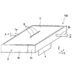
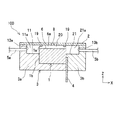
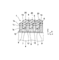
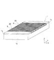
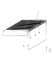
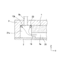
図1は、この発明のインクジェットヘッドの第1実施形態である斜視図を示している。図2は、図1におけるA−A’断面図を示す。図3は、インクジェットヘッドのノズルプレートを外した状態を示す。図1〜図3に示すように、このインクジェットヘッド100は、圧電基板1とノズルプレート2とホルダ部3とを備える。
(First embodiment)
FIG. 1 is a perspective view showing a first embodiment of an ink jet head according to the present invention. FIG. 2 is a cross-sectional view taken along the line AA ′ in FIG. FIG. 3 shows a state where the nozzle plate of the inkjet head is removed. As shown in FIGS. 1 to 3, the
上記圧電基板1は、一方向(X軸方向)に延在し互いに間隔を空けて平行に配列された複数の隔壁20を有する。この隣り合う隔壁20の間に個別インク溝6を形成する。
The
この各個別インク溝6は、一方向(X軸方向)に延在して両端が開口している。上記複数の個別インク溝6は、上記一方向に直交する他方向(Y軸方向)に互いに間隔をおいて平行に配列されている。上記個別インク溝6の両端は、上記圧電基板1の両端面に開口している。なお、分かりやすくするため、個別インク溝6の数や深さ等は、正確に図示してはいない。
Each
上記圧電基板1の上記一方向(X軸方向)の長さは、上記個別インク溝6の長さであるため、例えば、上記個別インク溝6の長さが5mmの場合には、上記圧電基板1の上記一方向(X軸方向)の長さは5mmあればよい。上記圧電基板1の上記他方向(Y軸方向)の長さは、上記個別インク溝6の数や幅やピッチによって異なる。
Since the length of the one direction (X-axis direction) of the
上記圧電基板1には、上記個別インク溝6の深さ方向における略中央にて分極方向が相反する2枚の圧電材料があらかじめ接着剤で貼りあわされている。この構成により、外部より電圧を印加した際に、個別インク溝6の2枚の圧電材料が互いに反対方向に変形することにより、個別インク溝6とノズルプレート2とで囲まれた領域である圧力発生室の容積を変えることによって、インクを吐出する。つまり、このインクジェットヘッドは、シェアモード型のインクジェットヘッドである。
Two piezoelectric materials having opposite polarization directions are bonded to the
上記ホルダ部3は、凹部を有し、この凹部に、上記圧電基板1が取り付けられる。上記圧電基板1は、接着剤を介して、上記ホルダ部3に接着固定されている。ここで、上記接着剤とは、例えば、弾性接着剤、瞬間接着剤、エポキシ系接着剤やUV接着剤などである。
The
上記ホルダ部3は、第1部材3aと第2部材3bとからなる。上記ホルダ部3は、第1共通インク溝11および第2共通インク溝21を有する。上記第1共通インク溝11は、上記複数の個別インク溝6の一端側において上記複数の個別インク溝6と連通する。上記第2共通インク溝21は、上記複数の個別インク溝6の他端側において上記複数の個別インク溝6と連通する。
The
上記ノズルプレート2は、上記隔壁20の上面に接触して、上記複数の個別インク溝6、上記第1共通インク溝11および上記第2共通インク溝21を上側から覆うように配置され、上記複数の個別インク溝6と共に複数の個別インク室6aを定義し、上記第1共通インク溝11と共に第1共通インク室11aを定義し、上記第2共通インク溝21と共に第2共通インク室21aを定義する。つまり、上記ノズルプレート2は、上記ホルダ部3の凹部を密閉する大きさである。上記ノズルプレート2は、上記個別インク溝6に対応する位置にノズル孔8を有する。
The
上記ホルダ部3の上記ノズルプレート2の接触面側端部は、上記圧電基板1の上記隔壁20の上面よりも、突出していない必要がある。これは、上記ホルダ部3の端部と上記隔壁20の上面とが、同時に、上記ノズルプレート2に接着するため、もし、上記ホルダ部3の端部が突出していた場合、上記ノズルプレート2が上記ホルダ部3によって持ち上げられて、上記ノズルプレート2が上記隔壁20の上面に接着できない、つまり、上記個別インク室6aの連通状態の領域が発生する。そして、上記個別インク室6aに連通した領域があると、インクが行き来することで、効率良くインクを吐出できず速度低下等の原因になる。
The end portion of the
上記ホルダ部3は、上記第1共通インク室11aに連通する第1流路口13aと、上記第2共通インク室21aに連通する第2流路口13bとを有する。上記第1流路口13aおよび上記第2流路口13bは、それぞれ、一つ設けられている。上記第1流路口13aは、インクの流入口であり、上記第2流路口13bは、インクの流出口である。上記ホルダ部3は、上記第1流路口13aが開口端である第1配管5aと、上記第2流路口13bが開口端である第2配管5bとを有する。
The
そして、上記インクジェットヘッド100では、(図示しない)供給タンクから上記第1配管5aを介して上記第1共通インク室11aにインクが供給され、このインクは、上記各個別インク室6aを通って、上記第2共通インク室21aに流入し、上記第2配管5bを介して廃液タンクへ流れる。
In the
一方、インクの吐出において、上記個別インク溝6の第1の電極部に印加された電圧により、上記隔壁20がせん断変形し、上記個別インク室6aの容積が変形して、上記ノズル孔8からインクが吐出される。
On the other hand, in the ejection of ink, the
ここで、上記インクジェットヘッド100は、例えば、上記ノズル孔8を下向き(重力方向)に配置して上記ノズル孔8からインクを下向きに吐出するように、使用される。つまり、上記インクジェットヘッド100は、Z軸方向を下向きにして、使用される。
Here, the
上記ノズル孔8は、上記個別インク溝6の長手方向(X軸方向)における中心に位置する。これは、上記ノズル孔8が上記個別インク溝6の長手方向における中心に位置したときが、外部電圧印加機構により上記個別インク溝6に電圧を印加した際に、上記個別インク溝6による圧力波の伝搬効率が最良となり、低い吐出電圧でインクを吐出できるからである。
The
図4に示すように、上記圧電基板1の端面には、上記各個別インク溝6に対応するように、第2の電極部(電極引き出し部)9が形成されている。この第2の電極部9は、上記個別インク溝6の内面に設けられた第1の電極部7に、電気的に接続している。上記第2の電極部9には、フレキシブルケーブル4が接続されている。なお、図4中、上記第1の電極部7および上記第2の電極部9を、斜線にて、示している。
As shown in FIG. 4, second electrode portions (electrode lead portions) 9 are formed on the end surface of the
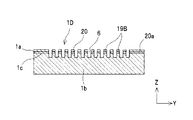
図2と図4に示すように、上記隔壁20は、互いに異なる分極方向をもつ上部圧電部1aおよび下部圧電部1bを積層して、形成される。上記上部圧電部1aは、例えば、0.15mmの薄板の圧電材料からなる。上記下部圧電部1bは、例えば、1.85mmの厚板の圧電材料からなる。上記上部圧電部1aと上記下部圧電部1bとは、接着部1cにより、貼りあわされている。
As shown in FIGS. 2 and 4, the
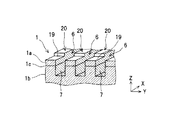
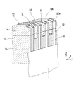
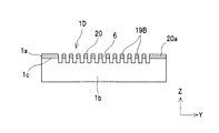
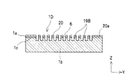
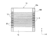
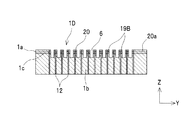
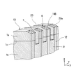
上記隔壁20の上面には、段差部19が設けられている。この段差部19は、上記隔壁20の上面よりも低くかつ上記個別インク溝6の底面よりも高くに位置する。上記段差部19は、上記ノズルプレート2から離隔する。上記段差部19は、上記隔壁20の幅方向の全部を切り欠いている。上記隔壁20の幅方向とは、上記隔壁20の配列方向(Y軸方向)をいう。
A
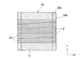
上記段差部19は、上記圧電基板1における上記第2の電極部9が設けられた端面に、設けられている。上記段差部19および上記第2の電極部9は、上記圧電基板1の上記両端面のそれぞれに、設けられている。上記圧電基板1の一方の端面に設けられている全ての上記段差部19は、上記個別インク溝6の長さ方向(X軸方向)に対して直交する方向(Y軸方向)に、配列されている。
The
上記隔壁20における上記段差部19の深さ方向に対応する全領域には、上記上部圧電部1aおよび上記下部圧電部1bが存在する。つまり、上記隔壁20における上記段差部19の深さ方向に対応する全領域には、上記接着部1cが存在する。
The upper
上記フレキシブルケーブル4は、図2に示すように、上記第1部材3aと上記第2部材3bとの接合面に位置している。つまり、上記第2部材3bの接合面には、上記フレキシブルケーブル4を嵌め込む凹部を有する。
As shown in FIG. 2, the
上記第2の電極部9は、外部から上記フレキシブルケーブル4を介して、電圧を印加され、印加された電圧は、上記第2の電極部9と導通している上記個別インク溝6の第1の電極部7に伝わる。この第1の電極部7に印加された電圧により、上記圧電基板1の上記個別インク溝6の壁面がせん断変形し、上記個別インク室6aの容積が変形して、押し出されたインクがノズル孔8から吐出される。
A voltage is applied to the
次に、上記構成のインクジェットヘッドの製造方法について説明する。 Next, a method for manufacturing the ink jet head having the above configuration will be described.
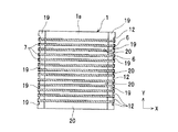
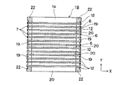
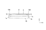
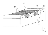
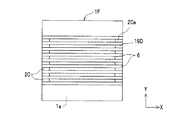
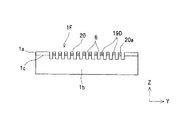
まず、図5Aの斜視図、図5Bの平面図および図5Cの側面図に示すように、個別インク溝形成工程を行い、圧電基板に、一方向に延在し互いに間隔を空けて平行に配列された複数の隔壁を形成して、この隣り合う隔壁の間に両端が開口する個別インク溝を形成する。つまり、アクチュエータ部材である圧電基板1にダイシングブレードを複数回一定方向(X軸方向)に走査して複数の個別インク溝6を形成する。
First, as shown in the perspective view of FIG. 5A, the plan view of FIG. 5B, and the side view of FIG. 5C, an individual ink groove forming step is performed, and the piezoelectric substrate extends in one direction and is arranged in parallel at intervals. A plurality of partition walls are formed, and individual ink grooves having both ends opened are formed between the adjacent partition walls. That is, a plurality of
ここで、大きな圧電基板から、ダイシングマシンによって四辺を切り出すことにより任意の大きさの圧電基板1とする。ダイシングマシンは、高い精度の直交度および平行度を有しているため、切り出した圧電基板1も高い直交度と平行度を有している。また、圧電基板1の厚さは2mmである。上部圧電部1aは、厚みがおよそ0.15mmであり、下部圧電部1bは、厚みがおよそ1.85mmであり、接着部1cは、厚みがおよそ10μmである。上部圧電部1aと下部圧電部1bとは、共に、圧電材料であるが、分極方向が逆向きである。
Here, a
また、圧電基板1の大きさは、5mm×50mmである。個別インク溝6の深さは、およそ300μm、幅は100μmとし、個別インク溝6のピッチは、約200μmで、個別インク溝6の数は200本とした。個別インク溝6の幅は、使用するダイシングブレードの厚みで変えることができ、個別インク溝6の深さは、ダイシングブレードの切り込み量を変えることにより変更することができる。
The size of the
また、個別インク溝6の深さは、接着部1cを個別インク溝6の深さ方向におけるおよそ中心に位置させるものである。上部圧電部1aと下部圧電部1bとは、分極方向が逆向きの圧電材料であるため、電圧を印加することにより逆向きに変形する。この変形により個別インク溝6の容積が変化して、インクを吐出することができる。接着部1cの位置が個別インク溝6の深さ方向におけるおよそ中心位置にあるのは、最も吐出効率がよいためであるが、これに限られるものではない。
The depth of the
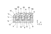
その後、図6Aの平面図および図6Bの側面図に示すように、導電膜形成工程を行い、上記圧電基板1の上記個別インク溝6の内面に上記第1の電極部7としての導電膜を形成すると共に、上記圧電基板1における上記個別インク溝6の両端が開口する両端面に、導電膜を形成する。
Thereafter, as shown in the plan view of FIG. 6A and the side view of FIG. 6B, a conductive film forming step is performed, and the conductive film as the
この実施の形態では、銅をスパッタ法により成膜した。なお、図中、導電膜を、斜線にて、示している。この実施形態におけるスパッタ法による導電膜形成工程では、圧電基板1の個別インク溝6を形成した面の裏側の面を除く全面に導電膜が形成されるため、目的以外の部分にも導電膜が形成される。
In this embodiment, copper is formed by sputtering. In the drawing, the conductive film is indicated by oblique lines. In the conductive film forming step by sputtering in this embodiment, the conductive film is formed on the entire surface except the surface on the back side of the surface on which the
このとき、接着部1cを覆っている部分の膜厚は、0.3μmであり、圧電基板1の両端面を覆っている部分の膜厚は、1μmである。個別インク溝6の内面に成膜された銅の膜厚と、個別インク溝6が開口する圧電基板1の端面に成膜された銅の膜厚とが、異なるのは、形状による銅のつきまわりの違いによるものである。
At this time, the film thickness of the part covering the
そして、図7Aの平面図、図7Bの側面図および図7Cの要部拡大斜視図に示すように、除去工程を行い、圧電基板1の個別インク溝6を形成した面における不要な導電膜を除去する。この除去工程では、例えば、圧電基板1の上部表面をダイシングブレードで複数回走査することで行うことができる。このとき、圧電基板1の個別インク溝6形成面において隣接する個別インク溝6同士が確実に絶縁するように、ダイシングブレードにより圧電基板1の表面もわずか(数μm)に研削する。わずかな量のみ研削するのは、接着部1cが個別インク溝6の深さのおよそ中心に位置させたままとするためである。除去工程後の圧電基板1には、個別インク溝6の内面に第1の電極部7と、圧電基板1の端面に導電膜とが、形成される。
Then, as shown in the plan view of FIG. 7A, the side view of FIG. 7B, and the enlarged perspective view of the main part of FIG. 7C, an unnecessary conductive film is formed on the surface of the
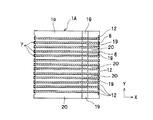
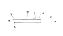
その後、図8Aの平面図、図8Bの側面図、図8Cの正面図および図8Dの要部拡大斜視図に示すように、段差部形成工程を行い、上記隔壁20の上面に、この上面よりも低くかつ上記個別インク溝6の底面よりも高い位置に、段差部19を形成する。つまり、圧電基板1の両端部に、除去工程と同様にダイシングブレードを走査して、圧電基板1の両端面および上面が切り欠かれるように、段差部19を形成する。圧電基板1の一方の端面において、個別インク溝6の長さ方向(X軸方向)に対して直交する方向(Y軸方向)に、段差部19を配列している。
Thereafter, as shown in the plan view of FIG. 8A, the side view of FIG. 8B, the front view of FIG. 8C, and the main part enlarged perspective view of FIG. 8D, a step portion forming step is performed. The
隔壁20の長さ方向(X軸方向)における段差部19の長さは、300μmであり、全ての隔壁20に、段差部19が設けられている。つまり、段差部19は、圧電基板1における個別インク溝6の並ぶ方向の両側面に開口している。また、段差部19の深さは、隔壁20の上面から80μmである。
The length of the
その後、図9Aの平面図、図9Bの側面図、図9Cの要部拡大斜視図および図9Dの全体斜視図に示すように、分離工程を行い、上記圧電基板1の上記両端面に形成された導電膜を、上記各個別インク溝6に対応するように分離して、第2の電極部9とする。つまり、圧電基板1の両端面に形成されている導電膜に対してダイシングブレードを複数回一定方向(Z軸方向)に走査して、分離溝12を形成する。この分離工程により、個別インク溝6にそれぞれ対応した第2の電極部9を形成する。このように、上記第2の電極部9は、上記圧電基板1の両端面に、設けられている。隣接する上記第2の電極部9は、分離溝12によって、電気的に分断されている。 個別インク溝6の内面に形成された第1の電極部7と第2の電極部9とは、個別インク溝6が開口する圧電基板1の端面において電気的に接続されている。
After that, as shown in the plan view of FIG. 9A, the side view of FIG. 9B, the enlarged perspective view of the main part of FIG. 9C, and the overall perspective view of FIG. The conductive film is separated so as to correspond to the
この実施形態では、分離溝12の深さを10μm、幅を50μmとして、個別インク溝6が開口する圧電基板1の端面にそれぞれ分離工程を行った。また、分離溝12を形成した部分は、個別インク溝6の間であり、隣接する個別インク溝6の間で電気的に導通することがない位置としている。このような分離工程を、個別インク溝6が開口する圧電基板1の端面の両側に行った。両側に分離工程を行うことにより、圧電基板1は対称形となるため、後工程において方向を間違うことはない。また、片側の第2の電極部9に損傷があった場合には、反対側の第2の電極部9を使用することができるため歩留まりを向上できる。
In this embodiment, the separation step is performed on the end surface of the
このようにして加工を施した圧電基板1の第2の電極部9に、外部から電圧が印加される導電部材を接続する。図10の斜視図に示すように、この実施の形態では、導電部材としてのフレキシブルケーブル4を用い、第2の電極部9との接続は、ACF(異方性導電フィルム;Anisotropic Conductive Film)接続を用いた。
A conductive member to which a voltage is applied from the outside is connected to the
フレキシブルケーブル4の他方の端部は、インクを吐出するために、直接または他部材を介して、外部電圧印加機構と接続される。本実施形態において、導電部材としてフレキシブルケーブルを使用するのは、フレキシブルケーブルは変形が容易であるため後工程においてプロセス上使用しやすく歩留まりの低下を抑制できるからであるが、必ずしもフレキシブルケーブルである必要はない。
The other end of the
そして、図11に示すように、ホルダ部3の第1部材3aに圧電基板1を接着する。第1部材3aと圧電基板1との接着面に上記接着剤を塗布して圧電基板1に押し当てた。
Then, as shown in FIG. 11, the
その後、図3に示すように、第1部材3aと第2部材3bとの接着面に、同様に、上記接着剤を塗布して、第1部材3aに第2部材3bを押し当てた。この状態を室温にて24時間保持して接着した。
Thereafter, as shown in FIG. 3, the adhesive was similarly applied to the bonding surface between the
つまり、取付工程を行い、上記ホルダ部3に上記圧電基板1を取り付けて、上記複数の個別インク溝6の一端に連通する上記第1共通インク溝11および上記複数の個別インク溝6の他端に連通する上記第2共通インク溝21を、上記ホルダ部3に形成する。
That is, an attachment process is performed, the
上記ホルダ部3は、上記第2の電極部9と上記フレキシブルケーブル4との接続部を、上記第1共通インク溝11および上記第2共通インク溝21に露出しないように覆っている。つまり、第2部材3bには、フレキシブルケーブル4と第2の電極部9との接続部分がインクに曝されないようにカバーが設けられている。
The
その後、図1に示すように、上記個別インク溝6、上記第1共通インク溝11および上記第2共通インク溝21を覆うようにノズルプレート2を接着して、インクジェットヘッドを完成する。
Thereafter, as shown in FIG. 1, the
具体的に述べると、まず、圧電基板1の上面とホルダ部3の上面とに、粘度が400cP程度のエポキシ接着剤を塗布した。このとき、圧電基板1の段差部19には、接着剤を塗布しない。段差部19は、圧電基板1の最上面ではないため、通常の方法、例えばローラーなどを使用して接着剤を塗布すれば、段差部19に接着剤が塗布されることはない。本実施形態ではPETフィルム上に接着剤を1cc程度のせ、金属製のローラーで充分引き伸ばすことによりローラー表面に接着剤を付着させ、圧電基板1の上面とホルダ部3の上面とに、ローラーを転がすことで接着剤を塗布した。このとき、塗布した接着剤の厚さは、およそ5μmである。
Specifically, first, an epoxy adhesive having a viscosity of about 400 cP was applied to the upper surface of the
そして、圧電基板1上面およびホルダ部3上面の上方に位置するCCDカメラで、段差部19の境界位置を複数点観察して基準位置とし、個別インク溝6の長さ方向における中心位置を算出した。この中心位置が、ノズル孔8が位置するべき位置である。ノズル孔8の位置が、圧電基板1の個別インク溝6の長手方向における中心位置となるように接着するのは、ノズル孔8が個別インク溝6の長手方向における中心に位置したときが、外部電圧印加機構により電圧を印加した際の圧力波の伝搬効率が最良で、低い吐出電圧でインクを吐出できるからである。
Then, with the CCD camera located above the upper surface of the
続いて、このCCDカメラを用いてノズルプレート2に形成されたノズル孔8を確認した。このCCDカメラは自動XYステージに積載されており、自由に位置を移動することができる構成となっている。段差部19とノズル孔8の位置をそれぞれ確認することにより、個別インク溝6の長さ方向における中心位置とノズル孔8のオフセット量を算出することができる。
Then, the
このようにして求めたオフセット量をもとに、真空吸着によりノズルプレート2をXYZ方向に自由に運搬することができるアームを用いて、ノズルプレート2を、ノズル孔8の位置が個別インク溝6の中心位置となるように運搬して、圧電基板1とホルダ部3に押し当て、室温で24時間放置して接着した。
Based on the offset amount obtained in this way, the
次に、上記構成のインクジェットヘッドの吐出試験について説明する。 Next, a discharge test of the ink jet head having the above configuration will be described.
ここで、上記構成(本実施形態)のインクジェットヘッドをインクジェットヘッドAとし、このインクジェットヘッドAを5個作製した。 Here, the inkjet head of the above configuration (this embodiment) was used as inkjet head A, and five inkjet heads A were produced.
一方、比較例として、インクジェットヘッドBを、5個作製した。このインクジェットヘッドBは、本実施形態のインクジェットヘッド製造方法のうち、段差部形成工程を行わない以外は、全く同じ構成と方法で作製した。このインクジェットヘッドBでは、段差部がない構成となっているため、圧電基板の大きさは個別インク溝の長さ方向が4.4mm、個別インク溝が並ぶ方向が50mm、厚みが2mmとした。ただし、ノズルプレートを接着する工程において、インクジェットヘッドBは段差部がないため、個別インク溝の長さ方向における端部を基準位置として、個別インク溝の中心位置を算出し、ノズル孔の位置とした。 On the other hand, five inkjet heads B were produced as comparative examples. This inkjet head B was manufactured with the completely same structure and method except not performing a level | step-difference part formation process among the inkjet head manufacturing methods of this embodiment. Since the ink jet head B has no stepped portion, the size of the piezoelectric substrate is 4.4 mm in the length direction of the individual ink grooves, 50 mm in the direction in which the individual ink grooves are arranged, and 2 mm in thickness. However, in the step of adhering the nozzle plate, since the inkjet head B does not have a stepped portion, the center position of the individual ink groove is calculated using the end portion in the length direction of the individual ink groove as a reference position, and the position of the nozzle hole did.
5個のインクジェットヘッドAと5個のインクジェットヘッドBにインクを充填し、外部電圧印加装置からフレキシブルケーブル4を介して、第1の電極部7および第2の電極部9に、10V程度の電圧を印加し、インクが吐出することを確認した。
Five ink jet heads A and five ink jet heads B are filled with ink, and a voltage of about 10 V is applied to the
このとき用いたインクは、アルコールとグリコールを混合したインクを用い、粘度はおよそ10cPに調整したものを使用した。以下の各実施形態において使用したインクは、第1実施形態と同様のものであるため、以下記載を省略する。 The ink used at this time was an ink in which alcohol and glycol were mixed, and the viscosity was adjusted to about 10 cP. The ink used in each of the following embodiments is the same as that in the first embodiment, and hence the description thereof is omitted.
また、飛翔するインクの吐出速度は、インクの吐出に同期させたストロボを一定周波数で発光させ、飛翔状態をCCDカメラで観察して算出する方法を用いた。インクジェットヘッドAおよびインクジェットヘッドBの各チャンネル間のインクの吐出速度の平均はおよそ8m/sであり、吐出速度ばらつきはいずれも±10%以内であった。ここで、チャンネルとは、個別インク溝6と連通しインクを吐出することができるノズル孔8を指している。
The ejection speed of the flying ink was calculated by emitting a strobe synchronized with the ejection of the ink at a constant frequency and observing the flight state with a CCD camera. The average of the ink ejection speed between the channels of the inkjet head A and the inkjet head B was about 8 m / s, and the variation in the ejection speed was within ± 10%. Here, the channel refers to the
ただし、圧電基板1の個別インク溝6が並ぶ方向における両端のチャンネルから吐出されたインクに関しては、その吐出速度を測定していない。本構造において、個別インク溝6は、ピッチ約200μmで200本形成されているため、個別インク溝6の幅は、100μmであるため、個別インク溝6間の隔壁は、幅100μmである。また、個別インク溝6は、200本を形成してあるため、個別インク溝6を形成した領域は、個別インク溝6が並ぶ方向におよそ40mmである。つまり、個別インク溝6が形成されていない領域は、圧電基板1の個別インク溝6が並ぶ方向にそれぞれ約5mmずつ存在する。
However, the ejection speed of the ink ejected from the channels at both ends in the direction in which the
よって、両端の個別インク溝6の圧電基板1の端部側の5mmの厚さの隔壁20と、他の個別インク溝6間の100μmの厚さの隔壁20とでは、5mmの厚さの隔壁20が非常に厚いため、この5mmの厚さの隔壁20に形成された第1の電極部7に電圧を印加してもほとんど変形しない。このため、両端のチャンネルから吐出されたインクの吐出速度は遅いため、測定するチャンネルからあらかじめ除外している。
Therefore, the
続いて、吐出周波数100KHzにてインクの連続吐出試験を行い長期信頼性の確認を行った。吐出滴数が5×10⁹滴を超えた時点で再度吐出速度を確認したところ、段差部19のないインクジェットヘッドBの5個のうち3個で、吐出速度がおよそ半分に低下するチャンネルが全体の10%程度発生した。インクの吐出速度の低下が発生しなかった2個のインクジェットヘッドBについても、吐出滴数5×10¹⁰滴まで吐出を行った後、吐出速度を測定したところ、インクの吐出速度が低下するチャンネルがおよそ10〜15%発生した。これらのインクの吐出速度が低下する吐出滴数の差についてはインクジェットヘッドBの個体差によるものである。
Subsequently, a continuous ink ejection test was performed at an ejection frequency of 100 KHz to confirm long-term reliability. When the ejection speed was confirmed again when the number of ejected drops exceeded 5 × 10 9 drops, 3 out of 5 of the 5 ink-jet heads B without the stepped
インクジェットヘッドAの5個は液滴数5×10¹⁰滴まで吐出を続けたのちに吐出速度を測定したが、全てのインクジェットヘッドAで吐出速度の低下するチャンネルは発生しなかった。 The discharge speed of the five inkjet heads A was measured after the discharge was continued until the number of droplets was 5 × 10 10 drops. However, in all the inkjet heads A, a channel in which the discharge speed decreased was not generated.
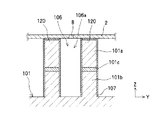
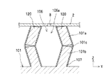
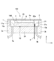
この吐出速度の低下の原因について以下に説明する。図12Aに、インクジェットヘッドBにおける個別インク溝106が開口した圧電基板101の側面を示す。インクジェットヘッドBでは、隔壁120が、上部圧電部101aと下部圧電部101bと接着部101cとから構成されている。上部圧電部101a上面とノズルプレート2とは、接着されている。上部圧電部101aと下部圧電部101bとは、分極方向が逆方向であり、図12Bに示すように、電圧を印加した際に、隔壁120は、上部圧電部101aと下部圧電部101bの間にある接着部101cを節として、逆方向に変形する。
The cause of the decrease in the discharge speed will be described below. FIG. 12A shows a side surface of the
このように、外部から電圧を印加することによって、圧力室(個別インク室106aのことであるが、ここではあえて圧力室と表現する)が変形して圧力波が発生する。この発生した圧力波は圧力室内を伝播していく。その際に、段差部のない隔壁120は、上下共に拘束されているため、接着部101c部分が最も変形量が大きくなる。これは、接着部101cが柔らかいことと、接着部101cが隔壁120の高さ方向における中央に位置している構造的な要因とによるものである。
In this way, by applying a voltage from the outside, the pressure chamber (which is the
そして、吐出回数の増加に従って隔壁120の変形を繰り返すことにより、個別インク溝106の内面を覆っている第1の電極部107が、接着部101cの部分で、断線して、上部圧電部101aと下部圧電部101bとが絶縁されてしまう。この絶縁により、圧力室の変形が、例えば下部圧電部1bのみとなって、圧力室の変形量が小さくなるため、吐出速度の低下や吐出量の減少など、吐出特性が劣化する。
Then, by repeating the deformation of the
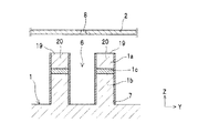
一方、インクジェットヘッドAの個別インク溝6が開口した圧電基板1の側面を、図13Aに示す。段差部19を有するインクジェットヘッドAでは、段差部19部分は上部圧電部1aが小さく、上部圧電部1a上面とノズルプレート2とは、接着されていない。このように、段差部19の上側は拘束されていないため、圧力波の伝播により、図13Bに示すように、隔壁20の付け根部分が最も変形することになる。つまり、最も変形する部分は、隔壁20の付け根であり、この部分が断線したとしても、上部圧電部材1aと下部圧電部材1bとは導通したままである。よって、吐出特性には影響を及ぼさない。
On the other hand, FIG. 13A shows a side surface of the
段差部19で上部圧電部1aと下部圧電部1bとが電気的に接続されているため、段差部19を形成してない隔壁20の部分で断線しても、上部圧電部1aには電圧が印加されるため吐出速度が低下することはない。つまり、図14の模式図に示すように、隔壁20における段差部19のない領域Z2にて、上部圧電部1aと下部圧電部1bとが電気的に断線しても、隔壁20における段差部19のある領域Z1にて、上部圧電部1aと下部圧電部1bとが電気的に接続しているので、矢印に示すように、領域Z1を介して、上部圧電部1aに電流が流れる。
Since the upper
さらに、圧電基板1の両端面に第2の電極部9を形成している場合には、両側の段差部19において変形量が少ないため、より接着部1cにおける断線を抑制する効果があって、電気的な信頼性が向上する。
Furthermore, in the case where the
一部のチャンネルでインクの吐出速度が著しく低下することは、インクが吐出されてから、インクにより描画される媒体へ着弾するまでの時間に大きな差が生じることとなる。これは、例えば、インクジェットヘッドを走査しながらインクを吐出するような場合には、インクの着弾する位置が大きく異なることとなるため、着弾精度を著しく低下する。また、走査せずに静止させてインクを吐出する場合でも、吐出速度が遅いインクは、風などの外乱の影響を受けやすいため、インクの着弾精度を著しく低下させることがある。このように不具合がない、段差部19を有するインクジェットヘッドAは、長期信頼性に優れたインクジェットヘッドであることを確認した。
If the ejection speed of the ink is remarkably reduced in some channels, there is a great difference in the time from the ejection of the ink to the landing on the medium drawn by the ink. This is because, for example, when ink is ejected while scanning an ink-jet head, the landing position of the ink is greatly different, so that the landing accuracy is significantly reduced. In addition, even when ink is ejected while being stationary without scanning, ink with a slow ejection speed is likely to be affected by disturbances such as wind, and thus the ink landing accuracy may be significantly reduced. Thus, it was confirmed that the ink jet head A having the stepped
上記構成のインクジェットヘッドによれば、上記ホルダ部3は、上記複数の個別インク溝6の一端側において上記複数の個別インク溝6と連通する第1共通インク溝11を有すると共に上記複数の個別インク溝6の他端側において上記複数の個別インク溝6と連通する第2共通インク溝21を有するので、上記第1共通インク溝11や上記第2共通インク溝21の幅や深さを適宜調整することにより、上記第1共通インク溝11や上記第2共通インク溝21の流路抵抗を、上記個別インク溝6の流路抵抗に比べ、充分小さくできて、インクジェットヘッド内において上記個別インク溝6を経由したインク流れを、容易に促進できる。
According to the ink jet head having the above-described configuration, the
また、上記圧電基板1の上記両端面のうちの少なくとも一方の端面には、上記第1の電極部7に電気的に接続する上記第2の電極部9が、上記各個別インク溝6に対応するように、設けられているので、上記圧電基板1における上記一方向の長さ(つまり、上記圧電基板1の上記両端面の間の長さ)を、上記個別インク溝6の上記一方向の長さのみの長さとすることができる。このように、上記圧電基板1を小型にできて、上記圧電基板1の高価な材料を抑えて、コストダウンを図ることができる。
The
また、上記隔壁20の上面には、この上面よりも低くかつ上記個別インク溝6の底面よりも高くに位置すると共に上記ノズルプレート2から離隔する段差部19が設けられているので、上記隔壁20における上記段差部19を形成した部分は、駆動電圧を印加しても、せん断変形が小さいため、上記個別インク溝6内面の上記第1の電極部7の断線を抑制することができる。
Further, the upper surface of the
したがって、インクジェットヘッド内においてインクの循環が円滑に行なわれ、インクジェットヘッドチップの小型化を図ることができると共に、電気的に長期信頼性を得ることができる。 Therefore, the ink is smoothly circulated in the ink jet head, the ink jet head chip can be downsized, and long-term reliability can be obtained electrically.
また、上記段差部19は、上記圧電基板1における上記第2の電極部9が設けられた端面に、設けられているので、上記第1の電極部7と上記第2の電極部9との接続部を、駆動電圧を印加した際の上記隔壁20のせん断変形が小さい領域に、位置できて、電気的に長期信頼性を向上できる。
Further, since the
また、上記段差部19は、上記圧電基板1の上記両端面のそれぞれに、設けられているので、上記第1の電極部7の断線を抑制する領域を、上記圧電基板1の両側に形成できて、電気的に長期信頼性を向上できる。
Further, since the
また、上記第2の電極部9は、上記圧電基板1の上記両端面のそれぞれに、設けられているので、上記第1の電極部7と上記第2の電極部9との接続部を、駆動電圧を印加した際の上記隔壁20のせん断変形が小さい領域に、位置できて、電気的に長期信頼性を向上できる。
Further, since the
また、上記隔壁20における上記段差部19の深さ方向に対応する全領域には、上記上部圧電部1aおよび上記下部圧電部1bが存在するので、上記隔壁20における上記段差部19の深さ方向に対応する全領域において、上記上部圧電部1aと上記下部圧電部1bとが電気的に接続されている。このため、電気的な信頼性を向上できる。
Further, since the upper
また、上記構成のインクジェットヘッドの製造方法によれば、上記ホルダ部3に上記圧電基板1を取り付けて、上記複数の個別インク溝6の一端に連通する上記第1共通インク溝11および上記複数の個別インク溝6の他端に連通する上記第2共通インク溝21を、上記ホルダ部3に形成する取付工程を備えるので、上記第1共通インク溝11や上記第2共通インク溝21の幅や深さを適宜調整することにより、上記第1共通インク溝11や上記第2共通インク溝21の流路抵抗を、上記個別インク溝6の流路抵抗に比べ、充分小さくできて、インクジェットヘッド内において上記個別インク溝6を経由したインク流れを、容易に促進できる。
Further, according to the method of manufacturing the ink jet head having the above-described configuration, the
また、上記圧電基板1の上記少なくとも一方の端面に形成された導電膜を、上記各個別インク溝6に対応するように分離して、上記第1の電極部7に電気的に接続する上記第2の電極部9とする分離工程を備えるので、上記圧電基板1における上記一方向の長さ(つまり、上記圧電基板1の上記両端面の間の長さ)を、上記個別インク溝6の上記一方向の長さのみの長さとすることができる。このように、上記圧電基板1を小型にできて、上記圧電基板1の高価な材料を抑えて、コストダウンを図ることができる。
Further, the conductive film formed on the at least one end face of the
また、上記隔壁20の上面に、この上面よりも低くかつ上記個別インク溝6の底面よりも高い位置に、段差部19を形成する段差部19形成工程を備えるので、上記隔壁20における上記段差部19を形成した部分は、駆動電圧を印加しても、せん断変形が小さいため、上記個別インク溝6内面の上記第1の電極部7の断線を抑制することができる。
Further, the
したがって、インクジェットヘッド内においてインクの循環が円滑に行なわれ、インクジェットヘッドチップの小型化を図ることができると共に、電気的に長期信頼性を得ることができる。 Therefore, the ink is smoothly circulated in the ink jet head, the ink jet head chip can be downsized, and long-term reliability can be obtained electrically.
(第2実施形態)
図15Aおよび図15Bは、この発明のインクジェットヘッドの第2実施形態を示している。上記第1実施形態と相違する点を説明すると、この第2実施形態では、段差部を形成する位置が相違する。なお、その他の構造は、上記第1実施形態と同じであるため、その説明を省略する。
(Second Embodiment)
15A and 15B show a second embodiment of the inkjet head of the present invention. The difference from the first embodiment will be described. In the second embodiment, the position where the step portion is formed is different. Since other structures are the same as those of the first embodiment, description thereof is omitted.
この第2実施形態の圧電基板1Aでは、段差部19を、圧電基板1Aの端面に開口しない位置に、形成している。圧電基板1Aの端面から1mmはなれた箇所に、段差部19を形成している。個別インク溝6の長さ方向における段差部19の長さを300μmとし、圧電材料の積層方向における段差部19の深さを100μmとする。
In the
このインクジェットヘッドにインクを充填し、インクの吐出速度のばらつきを測定したところ、吐出速度のばらつきは±10%以内であった。このとき、駆動電圧を調整し、吐出速度の平均がおよそ8m/sとなるようにした。続いて、長期信頼性を確認した。5×1010滴を吐出した後にも、インクの吐出速度がおよそ半分まで低下するチャンネルは発生しなかった。 When the ink jet head was filled with ink and the variation in the ink ejection speed was measured, the variation in the ejection speed was within ± 10%. At this time, the drive voltage was adjusted so that the average discharge speed was about 8 m / s. Subsequently, long-term reliability was confirmed. Even after discharging 5 × 10 10 drops, a channel in which the ink discharge speed decreased to approximately half did not occur.
つまり、段差部19は、個別インク溝6の長さ方向における隔壁20の一部に形成されていれば、段差部19を形成した部分の個別インク溝6の変形が小さくなり、断線を抑制する効果があることを確認できた。
That is, if the stepped
しかしながら、段差部19を、第2の電極部9を形成した側の圧電基板1Aの端面に形成することにより、第2の電極部9を形成した圧電基板1Aの端面も、駆動電圧の印加により変形が少なくなる領域となるため、第1の電極部7の断線の抑制に最も効果が高く適している。
However, by forming the
また、この第2実施形態のように、個別インク溝6の長さ方向における隔壁20の一部に段差部19を形成した場合、段差部19の端部と圧電基板1Aの端面とに挟まれた領域は吐出に寄与しない不要な部分となるため、インクジェットヘッドの小型化には適していない。
Further, when the
このことから、段差部19は、圧電基板1Aの端面に形成することが最も好ましいことを確認した。
From this, it was confirmed that the stepped
(第3実施形態)
次に、この発明のインクジェットヘッドの第3実施形態を説明する。上記第1実施形態と相違する点を説明すると、この第3実施形態では、段差部形成工程が相違する。なお、その他の構造は、上記第1実施形態と同じであるため、その説明を省略する。
(Third embodiment)
Next, a third embodiment of the inkjet head of the present invention will be described. The difference from the first embodiment will be described. In the third embodiment, the step portion forming process is different. Since other structures are the same as those of the first embodiment, description thereof is omitted.
この第3実施形態では、第1実施形態と同様に圧電基板の大きさは、個別インク溝の長さ方向が5mm、個別インク溝が並ぶ方向が50mm、厚さが2mmである。ノズルプレートを接着する工程において、塗布する接着剤の厚みは2μmとした。 In the third embodiment, as in the first embodiment, the size of the piezoelectric substrate is 5 mm in the length direction of the individual ink grooves, 50 mm in the direction in which the individual ink grooves are arranged, and 2 mm in thickness. In the step of adhering the nozzle plate, the thickness of the applied adhesive was 2 μm.
この圧電基板に、個別インク溝の長さ方向における段差部の長さを30μm、50μm、150μm、500μmとした。個別インク溝は長さ方向が開口しているため、個別インク溝の長さは5mmである。段差部の長さが溝の長さに占める割合を段差部率とよぶこととし、この構成では段差部率は、0.6%、1%、3%、10%となる。段差部の深さは全て120μmとした。このように段差部の長さの異なるインクジェットヘッドをそれぞれ5個ずつ作製した。 On this piezoelectric substrate, the lengths of the step portions in the length direction of the individual ink grooves were 30 μm, 50 μm, 150 μm, and 500 μm. Since the length direction of the individual ink groove is open, the length of the individual ink groove is 5 mm. The ratio of the length of the stepped portion to the length of the groove is referred to as the stepped portion ratio. In this configuration, the stepped portion ratio is 0.6%, 1%, 3%, and 10%. The depths of the step portions were all 120 μm. In this way, five ink jet heads each having different step lengths were produced.
はじめに、それぞれのインクジェットヘッドについて、第1実施形態と同様の方法を用いて初期のインクの吐出速度のばらつきを確認し、全てのインクジェットヘッドのインクの吐出速度のばらつきが±10%以内であることを確認した。 First, for each inkjet head, the variation in the initial ink ejection speed is confirmed using the same method as in the first embodiment, and the variation in the ink ejection speed of all the inkjet heads is within ± 10%. It was confirmed.
ただし、段差部の長さが異なるため、段差部を形成していない個別インク溝の長さも異なる。これは、個別インク溝の内壁の変形により圧力を発生させる領域の体積が異なることとなり、同じ電圧を加えたときのインクの吐出速度が異なることとなる。そのため、本実施形態では、印加する電圧をそれぞれのインクジェットヘッドによって変え、インクの吐出速度の平均がおおよそ同じ吐出速度となるように調整した。 However, since the lengths of the step portions are different, the lengths of the individual ink grooves not forming the step portions are also different. This is because the volume of the region where the pressure is generated differs due to the deformation of the inner wall of the individual ink groove, and the ink ejection speed when the same voltage is applied is different. Therefore, in this embodiment, the applied voltage is changed for each inkjet head, and the average of the ink ejection speed is adjusted to be approximately the same ejection speed.
続いて、第1実施形態と同様の方法を用いて長期信頼性を確認した。段差部の長さが30μm(段差部率0.6%)のインクジェットヘッドは5×10⁹滴まで吐出した時点では、インクの吐出速度が半分程度まで低下するチャンネルは発生しなかった。しかしながら、5×10¹⁰滴まで吐出した後に確認したところ、インクの吐出速度が半分まで低下したチャンネルが、5個のインクジェットヘッドのうち3個のインクジェットヘッドで発生した。一方、段差部の長さが50μm(段差部率1%)以上のインクジェットヘッドでは、5×10¹⁰滴まで吐出した後にも、インクの吐出速度がおよそ半分まで低下するチャンネルは発生しなかった。
Subsequently, long-term reliability was confirmed using the same method as in the first embodiment. When an ink jet head having a step portion length of 30 μm (step portion ratio: 0.6%) ejected up to 5 × 10 9 drops, a channel in which the ink ejection speed decreased to about half did not occur. However, when it was confirmed after discharging up to 5 × 10 10 drops, a channel in which the ink discharge speed was reduced to half was generated in three of the five inkjet heads. On the other hand, in the inkjet head having a step portion length of 50 μm (
次に、圧電基板の大きさを変え、同様にインクジェットヘッドを製作した。圧電基板の大きさは、個別インク溝の長さ方向が8mm、個別インク溝が並ぶ方向が50mm、厚さが2mmである。個別インク溝の形状やピッチ、本数は変えていない。つまり本圧電基板では個別インク溝の長さが8mmである。 Next, the size of the piezoelectric substrate was changed, and an inkjet head was similarly manufactured. The size of the piezoelectric substrate is 8 mm in the length direction of the individual ink grooves, 50 mm in the direction in which the individual ink grooves are arranged, and 2 mm in thickness. The shape, pitch, and number of individual ink grooves are not changed. That is, in this piezoelectric substrate, the length of the individual ink groove is 8 mm.
この圧電基板に対して、段差部を、40μm、80μm、120μmとしたインクジェットヘッドをそれぞれ作製した。全てのインクジェットヘッドのインクの吐出速度のばらつきが±10%以内であることを確認した後、長期信頼性を確認した。この際も印加する電圧をそれぞれ調整している。 Ink jet heads having stepped portions of 40 μm, 80 μm, and 120 μm were produced with respect to this piezoelectric substrate. Long-term reliability was confirmed after confirming that the variation in ink ejection speed of all inkjet heads was within ± 10%. Also in this case, the applied voltage is adjusted.
段差部の長さが40μm(段差部率0.5%)のインクジェットヘッドは、5×10⁹滴まで吐出した時点では、インクの吐出速度が半分程度まで低下するチャンネルは発生しなかった。しかしながら、5×10¹⁰滴まで吐出した後に確認したところ、インクの吐出速度が半分まで低下したチャンネルが、5個のインクジェットヘッドのうち4個のインクジェットヘッドで発生した。一方、段差部の長さが80μm(段差部率1%)以上のインクジェットヘッドでは、5×10¹⁰滴まで吐出した後にも、インクの吐出速度がおよそ半分まで低下するチャンネルは発生しなかった。
The ink jet head having a stepped portion length of 40 μm (stepped portion ratio 0.5%) did not generate a channel in which the ink ejection speed dropped to about half when it ejected up to 5 × 10 9 drops. However, when it was confirmed after discharging up to 5 × 10 10 drops, a channel in which the ink discharge speed was reduced to half was generated in four of the five inkjet heads. On the other hand, in an inkjet head having a step portion length of 80 μm (
段差部を形成した領域は、個別インク溝の内面の変形が小さい領域である。段差部の個別インク溝の長さ方向における長さが長いほど、個別インク溝の内面の変形が小さい領域が大きいため、接着部における第1の電極部の断線を抑制することができる。 The region where the step portion is formed is a region where the deformation of the inner surface of the individual ink groove is small. As the length of the stepped portion in the length direction of the individual ink groove is longer, the region where the deformation of the inner surface of the individual ink groove is smaller is larger, so that disconnection of the first electrode portion in the bonded portion can be suppressed.
本実施形態から、個別インク溝の長さに対して段差部の長さが1%未満の場合でも、効果があるが、個々のインクジェットヘッドの個体差の影響を無視できるほど充分ではなく、1%以上あることが好ましいことを確認できた。 From this embodiment, even when the length of the stepped portion is less than 1% with respect to the length of the individual ink groove, there is an effect, but it is not enough to ignore the influence of individual differences of individual inkjet heads. % Can be confirmed to be preferable.
また、段差部を形成していない領域の個別インク溝の長さを変えてしまうとインクジェットヘッドの吐出特性が変わってしまう。つまり、ある任意の吐出特性を有するインクジェットヘッドを作製する場合には、段差部を形成してない領域の個別インク溝の長さを変えることができないため、個別インク溝の長さ方向における、段差部の長さが長くなるほど、個別インク溝は長くなる。つまり圧電基板の大きさが大きくなり、圧電基板の大型化はコストの増大とインクジェットヘッドの大型化を招く。 Further, if the length of the individual ink groove in the region where the step portion is not formed is changed, the ejection characteristics of the ink jet head are changed. In other words, when an inkjet head having an arbitrary ejection characteristic is manufactured, the length of the individual ink groove in the region where the step portion is not formed cannot be changed. The longer the length of the part, the longer the individual ink groove. That is, the size of the piezoelectric substrate is increased, and the increase in size of the piezoelectric substrate causes an increase in cost and an increase in size of the inkjet head.
このことから最適な段差部の長さは、個別インク溝の長さの1%以上で、かつ、インクジェットヘッドの構造にあわせて最適化することが好ましい。 Therefore, it is preferable that the optimum length of the step portion is 1% or more of the length of the individual ink groove and is optimized in accordance with the structure of the inkjet head.
要するに、一つの隔壁に設けられた全ての段差部の一方向(隔壁の長さ方向)における長さは、この一つの隔壁の長さ方向における長さの1%以上である。したがって、隔壁の変形による、個別インク溝内面の第1の電極部の断線を十分に抑制できる。 In short, the length in one direction (the length direction of the partition walls) of all the steps provided in one partition wall is 1% or more of the length in the length direction of the one partition wall. Accordingly, disconnection of the first electrode portion on the inner surface of the individual ink groove due to the deformation of the partition wall can be sufficiently suppressed.
(第4実施形態)
次に、この発明のインクジェットヘッドの第4実施形態を説明する。上記第1実施形態と相違する点を説明すると、この第4実施形態では、段差部形成工程が相違する。なお、その他の構造は、上記第1実施形態と同じであるため、その説明を省略する。
(Fourth embodiment)
Next, a fourth embodiment of the ink jet head of the present invention will be described. The difference from the first embodiment will be described. In the fourth embodiment, the step portion forming process is different. Since other structures are the same as those of the first embodiment, description thereof is omitted.
この第4実施形態では、段差部の深さを10μm、20μm、50μmとした。これらの段差部は、圧電基板の両端面に形成した。段差部の個別インク溝の長さ方向における長さは、いずれも第1実施形態と同様に、300μmであり、両側に段差部を形成しているため、段差部率は、6%+6%=12%である。このようにして、段差部の深さを変えたインクジェットヘッドを、それぞれ5個ずつ作製した。 In this 4th Embodiment, the depth of the level | step-difference part was 10 micrometers, 20 micrometers, and 50 micrometers. These step portions were formed on both end faces of the piezoelectric substrate. The length of the stepped portion in the length direction of the individual ink grooves is 300 μm as in the first embodiment, and stepped portions are formed on both sides, so the stepped portion ratio is 6% + 6% = 12%. In this manner, five inkjet heads each having different depths of the step portions were produced.
10μmの深さの段差部を形成したインクジェットヘッドでは、5×10⁹滴のインクを吐出した後に、インクの吐出速度が半分まで低下するチャンネルが5個のうち3個で発生し、吐出速度が半分程度まで低下したチャンネルの数は、全体のおよそ15%であった。段差部の深さを10μmとしたインクジェットヘッドでは、段差部が接着剤で埋まり、ノズルプレートと接着されていたことにより段差部として機能しなかった。この段差部への接着剤の入り込みは、ノズルプレートを接着するに際の余剰の接着剤が、段差部に押し出され、押し出された余剰の接着剤が、毛細管力により広がったことが挙げられる。このとき、塗布した接着剤の厚さは、第1実施形態と同様でおよそ5μmであった。 In an inkjet head having a 10 μm deep stepped portion, after ejecting 5 × 10 9 drops of ink, 3 of the 5 channels in which the ink ejection speed drops to half occur, and the ejection speed is The number of channels dropped to about half was about 15% of the total. In the ink jet head in which the depth of the stepped portion was 10 μm, the stepped portion was filled with an adhesive and did not function as a stepped portion because it was bonded to the nozzle plate. As for the penetration of the adhesive into the stepped portion, surplus adhesive when adhering the nozzle plate is pushed out to the stepped portion, and the pushed out excess adhesive spreads by capillary force. At this time, the thickness of the applied adhesive was about 5 μm as in the first embodiment.
このような2種類の段差部への接着剤の入り込みは、接着剤の量を最小限に減らすことにより抑制することも可能であった。例えば、ノズルプレートを接着する際の接着剤は、以下のように減らすことができる。 Such entry of the adhesive into the two types of stepped portions could be suppressed by reducing the amount of the adhesive to a minimum. For example, the adhesive used when adhering the nozzle plate can be reduced as follows.
まず、ローラーに接着剤を転写するために、PETフィルムに乗せる接着剤の量を少なくし、PETフィルム上で、ローラーで接着剤を引き伸ばす回数と面積を増やすことにより、ローラーに転写される接着剤量を減らすことができる。 First, in order to transfer the adhesive to the roller, the amount of the adhesive placed on the PET film is reduced, and the adhesive is transferred to the roller by increasing the number of times the adhesive is stretched with the roller and the area on the PET film. The amount can be reduced.
このようにして、塗布した接着剤の厚みを2〜5μmとして、ノズルプレートを接着し、段差部への接着剤埋まり方を確認した。接着剤の厚みを3μm以上としたときには、段差部は完全に接着剤で埋まって、圧電基板とノズルプレートは接着された。 Thus, the thickness of the apply | coated adhesive was set to 2-5 micrometers, the nozzle plate was adhere | attached, and how the adhesive agent was buried in the level | step-difference part was confirmed. When the thickness of the adhesive was 3 μm or more, the step portion was completely filled with the adhesive, and the piezoelectric substrate and the nozzle plate were bonded.
しかしながら、接着剤の厚みがおよそ2μmのときに、段差部のおよそ7割まで接着剤で埋まり、3割は埋まらなかった。このように、接着剤量を制御して、10μmの深さの段差部の3割の長さが接着剤で埋まっていないインクジェットヘッドを製作し、吐出特性を確認したところ、初期の吐出速度のばらつきは±10%程度であり、5×10¹⁰滴吐出後にも、吐出速度が半分程度まで低下したチャンネルは発生しなかった。 However, when the thickness of the adhesive was about 2 μm, up to about 70% of the stepped portion was filled with the adhesive, and 30% was not filled. In this way, by controlling the amount of adhesive and manufacturing an ink jet head in which 30% of the stepped portion having a depth of 10 μm is not filled with the adhesive, and confirming the discharge characteristics, the initial discharge speed is The variation was about ± 10%, and even after discharging 5 × 10 10 drops, a channel in which the discharge speed was reduced to about half did not occur.
つまり、段差部は接着剤などで埋まらない限り、深さ10μmでも充分効果があることを確認できた。このとき、接着剤によって埋まっていない、段差部として機能した部分の長さは、片側の段差部でおよそ90μmであり、段差部率は両側あわせて3.6%となる。 That is, it was confirmed that the stepped portion was sufficiently effective even at a depth of 10 μm unless it was filled with an adhesive or the like. At this time, the length of the portion functioning as the step portion that is not buried by the adhesive is approximately 90 μm at the step portion on one side, and the step portion ratio is 3.6% on both sides.
段差部を有するインクジェットヘッドを大量に生産する場合には、それぞれの部材の寸法精度や、圧電基板とホルダ部との間のギャップの制御など、製造工程において発生する個々のばらつきに対して、接着剤の塗布量だけで制御することは困難である。 When mass-producing inkjet heads with stepped parts, bonding to individual variations that occur in the manufacturing process, such as the dimensional accuracy of each member and the control of the gap between the piezoelectric substrate and the holder part. It is difficult to control only by the application amount of the agent.
また、塗布する接着剤の量を極力まで減らしたにもかかわらず、接着剤が段差部に入り込むことにより、段差部率が大きく下がるため好ましくない。この接着剤の入り込みによる段差部率の低下を避けるために、段差部の長さをあらかじめ長くすることは、インクジェットヘッドの大型化となるため好ましくない。 In addition, even though the amount of adhesive to be applied is reduced as much as possible, the step ratio is greatly reduced when the adhesive enters the step portion, which is not preferable. In order to avoid a decrease in the stepped portion ratio due to the entry of the adhesive, it is not preferable to lengthen the length of the stepped portion in advance because the size of the ink jet head is increased.
これに対し、段差部の深さを20μm以上としたインクジェットヘッドでは、ノズルプレートの接着のために塗布する接着剤の厚みを、2〜5μmとしても、段差部はほとんど埋まることはなかった。これは、段差部の深さが、塗布する接着剤の厚さに対して充分大きく、余剰の接着剤が、段差部へ入り込んでも、毛細管力によって広がることはほとんどなかった。つまり、段差部の深さを20μm以上とすることにより、接着剤の塗布量のばらつきに対して充分余裕があり、かつ、段差部の長さを必要以上に大きくする必要がないことを確認した。 In contrast, in the ink jet head in which the depth of the step portion is 20 μm or more, the step portion is hardly buried even when the thickness of the adhesive applied for bonding the nozzle plate is 2 to 5 μm. This is because the depth of the stepped portion is sufficiently larger than the thickness of the adhesive to be applied, and even when excess adhesive enters the stepped portion, the stepped portion hardly spreads by the capillary force. In other words, it was confirmed that by setting the depth of the step portion to 20 μm or more, there is a sufficient margin for variation in the amount of adhesive applied, and it is not necessary to increase the length of the step portion more than necessary. .
段差部の深さを20μmおよび50μmとしたインクジェットヘッドについても、初期吐出特性と長期信頼性を確認し、5×10¹⁰滴吐出後も、吐出速度が半分程度まで低下するチャンネルは、5個全てのインクジェットヘッドで発生しなかった。 Even with inkjet heads with step depths of 20 μm and 50 μm, the initial discharge characteristics and long-term reliability were confirmed, and after 5 × 10 10 droplets were discharged, all five channels had a discharge rate reduced to about half. It did not occur with the inkjet head.
本実施形態から、段差部への接着剤の埋まりが発生しない、段差部を形成するためには、段差部の深さの最も深い部分は、少なくとも20μm以上であることが好ましいことを確認した。 From this embodiment, it was confirmed that the deepest part of the stepped portion is preferably at least 20 μm or more in order to form the stepped portion in which the adhesive is not buried in the stepped portion.
要するに、段差部における上面からの深さは、20μm以上である。したがって、段差部が他工程における接着剤などで完全に埋まって、段差部としての機能を低下させることを避けることができる。 In short, the depth from the upper surface of the stepped portion is 20 μm or more. Therefore, it can be avoided that the step portion is completely filled with an adhesive or the like in another process and the function as the step portion is deteriorated.
(第5実施形態)
次に、この発明のインクジェットヘッドの第5実施形態を説明する。上記第1実施形態と相違する点を説明すると、この第5実施形態では、段差部の深さが相違する。なお、その他の構造は、上記第1実施形態と同じであるため、その説明を省略する。
(Fifth embodiment)
Next, a fifth embodiment of the ink jet head of the present invention will be described. The difference from the first embodiment will be described. In the fifth embodiment, the depth of the step portion is different. Since other structures are the same as those of the first embodiment, description thereof is omitted.
この第5実施形態では、段差部の深さを100μm、130μm、200μmとした。これらの段差部は、圧電基板の両端面に形成した。段差部の個別インク溝の長さ方向における長さは、いずれも、第1実施形態と同様に300μmであり、両側にあるため段差部率は、6%+6%で12%である。このようにして、段差部の深さを変えたインクジェットヘッドをそれぞれ5個ずつ作製した。 In the fifth embodiment, the depth of the step portion is 100 μm, 130 μm, and 200 μm. These step portions were formed on both end faces of the piezoelectric substrate. The lengths of the individual ink grooves in the length direction of the step portions are 300 μm as in the first embodiment, and the step portion ratio is 6% + 6% and 12% because they are on both sides. In this way, five inkjet heads each having different depths of the step portions were produced.
段差部の深さを100μm、130μmとしたインクジェットヘッドでは、段差部への接着剤の入り込みはほとんどなかった。このインクジェットヘッドについても、初期吐出特性と長期信頼性を確認した。初期における吐出速度のばらつきはすべて±10%以内であった。また、5×10¹⁰滴吐出後も、吐出速度が半分程度まで低下するチャンネルは、段差部の深さを100μm、130μmとした全てのインクジェットヘッドで発生しなかった。 In the ink jet head in which the depth of the step portion was 100 μm and 130 μm, the adhesive hardly entered the step portion. The initial discharge characteristics and long-term reliability of this inkjet head were also confirmed. The variations in the discharge speed at the initial stage were all within ± 10%. Further, even after discharging 5 × 10 10 drops, a channel in which the discharge speed decreased to about half was not generated in all the ink jet heads having the depth of the step portion of 100 μm and 130 μm.
段差部の深さを200μmとしたインクジェットヘッドでも、接着剤の段差部への入り込みはほとんど確認されなかった。初期の吐出速度のばらつきも±10%であり問題なかったが、5×10¹⁰滴吐出後には、吐出速度が半分程度まで低下するチャンネルが約10%程度発生した。これは、段差部の深さが200μmと深いため、隔壁における段差部を形成した部分には、下部圧電部しかない。また、段差部を第2の電極部を形成した側の圧電基板の端部に形成しているため、第2の電極部を形成した圧電基板の端面においても上部圧電部と下部圧電部は電気的に接続されていない。つまり、圧電基板において、上部圧電部と下部圧電部とは、段差部を形成していない第1の電極部でのみ電気的に接続されている。この構造は、段差部を形成しない構造と同じか、もしくは、第2の電極部を形成した圧電基板の端面においても、上部圧電部と下部圧電部とが電気的に接続されていないため、段差部を形成しない構造よりも、上部圧電部と下部圧電部との電気的な接続箇所が減っている。この構造では、電圧を印加して個別インク溝の内面を変形させた際に、接着部において第1の電極部が断線したチャンネルは、インクの吐出速度が半分程度まで低下した。 Even in an ink jet head having a stepped portion having a depth of 200 μm, almost no entry of the adhesive into the stepped portion was confirmed. The initial discharge speed variation was ± 10%, which was not a problem. However, after discharging 5 × 10 10 drops, about 10% of channels in which the discharge speed decreased to about half occurred. This is because the depth of the step portion is as deep as 200 μm, and therefore the portion where the step portion is formed in the partition wall has only the lower piezoelectric portion. Further, since the stepped portion is formed at the end of the piezoelectric substrate on the side where the second electrode portion is formed, the upper piezoelectric portion and the lower piezoelectric portion are electrically connected to the end surface of the piezoelectric substrate on which the second electrode portion is formed. Is not connected. That is, in the piezoelectric substrate, the upper piezoelectric portion and the lower piezoelectric portion are electrically connected only at the first electrode portion that does not form the stepped portion. This structure is the same as the structure in which the step portion is not formed, or the upper piezoelectric portion and the lower piezoelectric portion are not electrically connected even at the end face of the piezoelectric substrate on which the second electrode portion is formed. The number of electrical connection points between the upper piezoelectric portion and the lower piezoelectric portion is reduced as compared with the structure in which no portion is formed. In this structure, when a voltage is applied to deform the inner surface of the individual ink groove, the ink ejection speed of the channel where the first electrode portion is disconnected at the adhesive portion is reduced to about half.
つまり、段差部を形成する場合には、段差部を形成した部分の個別インク溝の内壁において、少なくとも一部が上部圧電部と下部圧電部が電気的に接続されている必要がある。特に、段差部を形成した部分の全領域において上部圧電部と下部圧電部が電気的に接続されていることが好ましい。 In other words, when forming the step portion, at least a part of the inner piezoelectric wall of the portion where the step portion is formed needs to be electrically connected to the upper piezoelectric portion and the lower piezoelectric portion. In particular, it is preferable that the upper piezoelectric portion and the lower piezoelectric portion are electrically connected in the entire region where the step portion is formed.
このように、上部圧電部と下部圧電部とが電気的に接続されるためには、段差部を形成した部分の個別インク溝の内壁が、分極方向が異なる圧電材料の接着界面を含む必要がある。また、段差部を形成した部分の個別インク溝の一部のみが分極方向が異なる圧電材料の接着界面を含むには、接着界面を含む領域の長さが、少なくとも個別インク溝の全長の1%以上なければ効果がないことを確認している。 Thus, in order for the upper piezoelectric portion and the lower piezoelectric portion to be electrically connected, the inner wall of the individual ink groove in the portion where the step portion is formed needs to include an adhesion interface of piezoelectric materials having different polarization directions. is there. Further, in order that only a part of the individual ink groove in the portion where the step portion is formed includes the adhesive interface of the piezoelectric material having a different polarization direction, the length of the region including the adhesive interface is at least 1% of the total length of the individual ink groove. It has been confirmed that there is no effect unless it is above.
つまり、本実施形態より、段差部を形成した部分の個別インク溝の内壁の少なくとも一部が、分極方向が異なる圧電材料の接着界面を含む必要があり、また、段差部を形成した部分の個別インク溝の内壁の全てが、分極方向が異なる圧電材料の接着界面を含むことが好ましいことを確認した。 That is, according to the present embodiment, at least a part of the inner wall of the individual ink groove in the portion where the step portion is formed needs to include an adhesion interface of piezoelectric materials having different polarization directions, and the individual portion where the step portion is formed is included. It was confirmed that all the inner walls of the ink groove preferably include an adhesion interface of piezoelectric materials having different polarization directions.
要するに、隔壁における段差部の深さ方向に対応する全領域には、上部圧電部および下部圧電部が存在する。したがって、隔壁における段差部の深さ方向に対応する全領域において、上部圧電部と下部圧電部とが電気的に接続されている。このため、電気的な信頼性を向上できる。 In short, the upper piezoelectric portion and the lower piezoelectric portion exist in the entire region corresponding to the depth direction of the step portion in the partition wall. Therefore, the upper piezoelectric portion and the lower piezoelectric portion are electrically connected in the entire region corresponding to the depth direction of the step portion in the partition wall. For this reason, electrical reliability can be improved.
(第6実施形態)
図16Aおよび図16Bは、この発明のインクジェットヘッドの第6実施形態を示している。上記第1実施形態と相違する点を説明すると、この第6実施形態では、圧電基板の四隅に段差部がない点が相違する。なお、その他の構造は、上記第1実施形態と同じであるため、その説明を省略する。
(Sixth embodiment)
16A and 16B show a sixth embodiment of the inkjet head of the present invention. The difference from the first embodiment will be described. The sixth embodiment is different in that there are no step portions at the four corners of the piezoelectric substrate. Since other structures are the same as those of the first embodiment, description thereof is omitted.
この第6実施形態の圧電基板1Bでは、第1実施形態と同様に、段差部19を形成した後、隣接する個別インク溝6の間にある隔壁20以外の部分に形成された段差部19を、封止部材22で接着剤を介して封止している。なお、わかりやすくするため、この封止部材22をハッチングにて示している。
In the
この圧電基板1Bを使用して作製したインクジェットヘッドを、インクジェットヘッドCとする。また、比較例として、封止部材22で封止を行わず、第1実施形態と同じ製造方法で作製したインクジェットヘッドAを用意した。
An ink jet head manufactured using this
いずれのインクジェットヘッドでも、初期および5×10¹⁰滴のインク吐出後も共に、インクの吐出速度が初期の半分程度まで低下するチャンネルは発生しなかった。つまり、個別インク溝6が並ぶ方向における圧電基板1の両端には段差部19は必要なく、隣接する個別インク溝6の間の隔壁20にのみ形成されていれば、接着部1cで発生する第1の電極部7の断線を抑制することができることを確認した。
In any of the inkjet heads, a channel in which the ink ejection speed was reduced to about half of the initial stage was not generated both in the initial stage and after the ejection of 5 × 10 10 drops. That is, the
しかし、封止部材22で封止を行わずに作製したインクジェットヘッドAに、はじめにインクを充填した際に、最端の段差部19に気泡が残存することがあった。ここで、最端の段差部19とは、図16Bにおいて、封止部材22で封止した部分をいう。
However, when the ink jet head A manufactured without sealing with the sealing
この最端の段差部19は、段差部19とノズルプレート2とホルダ部3とで囲まれた袋小路構造となっている。このような袋小路構造では、インクの動きが少ないため、この袋小路構造部分にひとたび気泡が残存すると、除去することが困難である。
The extreme
インクジェットヘッド内部に残存した気泡は、電圧を印加することにより発生した圧力をロスするため、インクの吐出量の減少やインクの不吐出の原因となるため好ましくない。 Bubbles remaining in the ink jet head are not preferable because the pressure generated by applying a voltage is lost, which causes a decrease in ink discharge amount and non-discharge of ink.
よって、インクジェットヘッドAにインクを初期充填する際には、この袋小路構造部分に気泡が残存しないように、注意深くインクを充填する必要性があった。また、微粒子が分散したインクを用いた場合には、このようなインクの動きの少ない袋小路部分に、粒子が沈降する虞もあるため袋小路構造は好ましくない。 Therefore, when the ink is initially filled in the inkjet head A, it is necessary to carefully fill the ink so that bubbles do not remain in the bag path structure portion. In addition, when ink in which fine particles are dispersed is used, the bag path structure is not preferable because there is a possibility that the particles may settle in such a path path where the ink moves little.
一方、封止部材22を用いて封止したインクジェットヘッドCでは、このような気泡の残存が見られなかった。これは、封止部材22により、あらかじめ袋小路構造となる部分を封止していることによる。このように、個別インク溝6を形成した部分にのみ段差部19を形成することにより、接着部1cにおける第1の電極部7の断線を抑制し、かつ、初期にインクを充填する際の気泡の残存を抑制することができることがわかった。
On the other hand, in the ink jet head C sealed using the sealing
要するに、この第6実施形態の圧電基板1Bでは、段差部19は、隣り合う個別インク溝6の間に位置する隔壁20にのみ、設けられている。したがって、複数の隔壁20の配列方向の最端にある隔壁20には、段差部19がない。このため、混入した気泡は、最端の隔壁20に、残存しない。
In short, in the
なお、本実施の形態では、段差部形成工程をダイシングマシンによって行った後、封止部材22で一部を封止したが、この加工方法に限らない。つまり、あらかじめ個別インク溝6の間の隔壁20にのみ、段差部19を形成することができる加工方法を用いればよい。
In the present embodiment, after the stepped portion forming step is performed by a dicing machine, a part is sealed with the sealing
(第7実施形態)
次に、この発明のインクジェットヘッドの第7実施形態を説明する。上記第1実施形態と相違する点を説明すると、この第7実施形態では、圧電基板の加工工程が相違する。なお、その他の構造は、上記第1実施形態と同じであるため、その説明を省略する。
(Seventh embodiment)
Next, a seventh embodiment of the ink jet head of the present invention will be described. The difference from the first embodiment will be described. In the seventh embodiment, the processing steps of the piezoelectric substrate are different. Since other structures are the same as those of the first embodiment, description thereof is omitted.
この第7実施形態では、第1実施形態と同様に、ダイシングマシンにより大きな圧電基板から10.5mm×50mmの大きさの圧電基板を切り出した。これは、およそ第1実施形態で使用した圧電基板のほぼ2個分の大きさである。圧電基板の厚さも第1実施形態と同様で2mmであり、上部圧電部、下部圧電部および接着部は、第1実施形態と同様の厚さを有している。 In the seventh embodiment, similarly to the first embodiment, a piezoelectric substrate having a size of 10.5 mm × 50 mm was cut out from a large piezoelectric substrate by a dicing machine. This is approximately the size of approximately two piezoelectric substrates used in the first embodiment. The thickness of the piezoelectric substrate is 2 mm as in the first embodiment, and the upper piezoelectric portion, the lower piezoelectric portion, and the bonding portion have the same thickness as in the first embodiment.
続いて、第1実施形態と同様に導電膜形成工程を行った。本実施形態における導電膜も銅であり、接着部1c部分における銅の膜厚は0.3μmとした。さらに,第1実施形態と同様に除去工程を行った後、個別インク溝の長さ方向における中央部分で、それぞれが5mm×50mmとなるように2分割した。この工程を分断工程と呼ぶ。
Subsequently, a conductive film forming step was performed as in the first embodiment. The conductive film in the present embodiment is also copper, and the film thickness of copper in the bonded
分断工程はダイシングマシンを用いた。はじめに5mm×50mmの2個分である10mm×50mmよりもわずかに大きいサイズとしたのは、ダイシングマシンによる分断する際のブレードの厚み分を含んでいるためである。分割された圧電基板のひとつひとつがインクジェットヘッドで使用する圧電基板となる。 A dicing machine was used for the cutting process. The reason why the size is slightly larger than 10 mm × 50 mm, which is two pieces of 5 mm × 50 mm, is because it includes the thickness of the blade when it is cut by a dicing machine. Each of the divided piezoelectric substrates becomes a piezoelectric substrate used in the inkjet head.
このように、あらかじめ大きな基板に個別インク溝形成工程と導電膜形成工程を行った後、分断工程を追加することにより、圧電基板の一方の端面にだけ導電膜が形成された圧電基板を2個用意することができる。このように、除去工程後に大きな圧電基板をいくつかに分断することによって、効率よくインクジェットヘッド用の圧電基板の加工において、タクトタイムを短縮することができる。 In this way, after performing the individual ink groove forming step and the conductive film forming step on a large substrate in advance, by adding a dividing step, two piezoelectric substrates having a conductive film formed only on one end surface of the piezoelectric substrate are obtained. Can be prepared. In this way, by dividing the large piezoelectric substrate into several parts after the removing step, the tact time can be shortened in the processing of the piezoelectric substrate for the inkjet head efficiently.
この後、第1実施形態と同様の工程を行い、インクジェットヘッドを作製した。ただし、分断工程を行った圧電基板では、個別インク溝が開口する端面のうち片側にしか導電膜が形成されていない。よって、分離工程は導電膜が形成された圧電基板の側面にのみに対して行った。また、段差部形成工程では、圧電基板の両端面に段差部を形成したものと、第2の電極部を形成した一方の端面にのみ段差部を形成したものとを、2種類作製した。 Thereafter, the same process as that of the first embodiment was performed to produce an ink jet head. However, in the piezoelectric substrate subjected to the dividing step, the conductive film is formed only on one side of the end face where the individual ink grooves are opened. Therefore, the separation process was performed only on the side surface of the piezoelectric substrate on which the conductive film was formed. In the step portion forming step, two types were produced: one in which the step portion was formed on both end faces of the piezoelectric substrate and one in which the step portion was formed only on one end surface on which the second electrode portion was formed.
一方の端面にのみ段差部を形成したインクジェットヘッドの段差部率は6%であり、圧電基板の両端面に段差部を形成したインクジェットヘッドの段差部率は12%である。 The step ratio of the ink jet head in which the step portion is formed only on one end surface is 6%, and the step ratio of the ink jet head in which the step portion is formed on both end faces of the piezoelectric substrate is 12%.
段差部が一方の端面にのみ形成されているインクジェットヘッドと、段差部が両端面に形成されているインクジェットヘッドとでは、初期状態におけるインク吐出速度ばらつきは、±10%以内であり違いはなかった。また、5×10¹⁰滴を吐出した後に吐出速度を再度測定しても、いずれのインクジェットヘッドも吐出速度が半分程度まで低下したチャンネルは発生せず差はなかった。 Ink jet heads in which the step portion is formed only on one end face and the ink jet head in which the step portion is formed on both end faces have an ink discharge speed variation in the initial state within ± 10%, and there is no difference. . Further, even when the ejection speed was measured again after ejecting 5 × 10 10 drops, no channel was found in which the ejection speed was reduced to about half in any inkjet head, and there was no difference.
よって、分断工程を追加することにより、インクジェットヘッドを製造するタクトタイムを短縮することができることを確認した。 Therefore, it was confirmed that the tact time for manufacturing the inkjet head can be shortened by adding a dividing step.
要するに、段差部および第2の電極部は、圧電基板の一方の端面に、設けられている。したがって、例えば、大きな圧電基板をいくつかに分断することによって、圧電基板を効率よく製造できて、タクトタイムを短縮することができる。 In short, the step portion and the second electrode portion are provided on one end face of the piezoelectric substrate. Therefore, for example, by dividing a large piezoelectric substrate into several parts, the piezoelectric substrate can be efficiently manufactured, and the tact time can be shortened.
(第8実施形態)
次に、この発明のインクジェットヘッドの第8実施形態を説明する。上記第1実施形態と相違する点を説明すると、この第8実施形態では、導電膜形成工程で成膜した導電膜の厚さが相違する。なお、その他の構造は、上記第1実施形態と同じであるため、その説明を省略する。
(Eighth embodiment)
Next, an ink jet head according to an eighth embodiment of the present invention will be described. The difference from the first embodiment will be described. In the eighth embodiment, the thickness of the conductive film formed in the conductive film forming step is different. Since other structures are the same as those of the first embodiment, description thereof is omitted.
この第8実施形態では、導電膜形成工程に、第1実施形態と同様に、スパッタ法を用いて銅を成膜し、成膜した銅の個別インク溝の内面における膜厚を、接着部を覆っている部分で1μm、3μm、5μmの3種類とした。成膜した銅の膜厚は、スパッタによる成膜時間を変えることで任意の膜厚とすることができる。 In the eighth embodiment, in the conductive film forming step, as in the first embodiment, a copper film is formed by the sputtering method, and the film thickness on the inner surface of the individual ink groove of the formed copper is changed to the bonding portion. The covered parts were three types of 1 μm, 3 μm, and 5 μm. The film thickness of the deposited copper can be set to an arbitrary film thickness by changing the film formation time by sputtering.
まず、段差部を有し、これら導電膜の異なる5種類のインクジェットヘッドをそれぞれ1個ずつ作製した。これらのインクジェットヘッドを、導電膜が薄い順にインクジェットヘッドA’−1からインクジェットヘッドA’−3と呼ぶ。また、比較例として、段差部がない以外はインクジェットヘッドA’と同じで、導電膜の厚さが1μm、3μm、5μmの3種類のインクジェットヘッドをインクジェットヘッドB’−1から インクジェットヘッドB’−3と呼ぶこととする。 First, five types of ink jet heads each having a stepped portion and having different conductive films were produced. These inkjet heads are referred to as inkjet head A′-1 to inkjet head A′-3 in the order of decreasing conductive film. In addition, as a comparative example, the same as the inkjet head A ′ except that there is no stepped portion, three types of inkjet heads having a conductive film thickness of 1 μm, 3 μm, and 5 μm are designated as inkjet head B′-1 to inkjet head B′−. Let's call it 3.
それぞれのインクジェットヘッドに電圧を印加して初期の飛翔するインクの状態を観察し、全てのインクジェットヘッドで、初期段階における飛翔するインクの吐出速度のばらつきが±10%以内であることを確認した。 By applying a voltage to each inkjet head and observing the initial flying ink state, it was confirmed that the variation in the ejection speed of the flying ink in the initial stage was within ± 10% in all the inkjet heads.
続いて、長期信頼性を確認するため、それぞれのインクジェットヘッドを100KHzで5×10¹⁰滴吐出させ、飛翔するインクの吐出速度の変化を確認した。段差部を有するインクジェットヘッドA’−1からインクジェットヘッドA’−3では、吐出速度がおよそ半分まで低下したチャンネルはなく、段差部の効果を確認することができた。しかしながら、インクジェットヘッドA’−3では、インク吐出速度のばらつきがやや大きくなり、±15%程度であった。 Subsequently, in order to confirm long-term reliability, each inkjet head was ejected at 5 × 10 10 drops at 100 kHz, and changes in the ejection speed of the flying ink were confirmed. In the inkjet head A′-1 to the inkjet head A′-3 having the step portion, there was no channel in which the discharge speed was reduced to about half, and the effect of the step portion could be confirmed. However, in the inkjet head A′-3, the variation in the ink discharge speed was slightly large, which was about ± 15%.
一方、インクジェットヘッドB’−1とインクジェットヘッドB’−2では、インクの吐出速度が半分程度に低下したチャンネルが全体のおよそ10%発生した。最も厚い導電膜を有するインクジェットヘッドB’−3では、吐出速度が半分程度まで低下するチャンネルは発生しなかったが、インクジェットヘッドA’−3と同様に吐出速度のばらつきは、±16%程度と低下した。 On the other hand, in the ink jet head B'-1 and the ink jet head B'-2, approximately 10% of the channels in which the ink ejection speed was reduced to about half were generated. In the inkjet head B′-3 having the thickest conductive film, a channel in which the ejection speed was reduced to about half did not occur. However, as in the inkjet head A′-3, the variation in ejection speed was about ± 16%. Declined.
インクジェットヘッドB’−3は、接着部における第1の電極部の厚みが5μmと厚いことにより、変形による応力によって、第1の電極部が断線することはなく、吐出速度が半分程度まで低下するチャンネルは発生しなかった。 Ink-jet head B′-3 has a thickness of the first electrode portion of 5 μm at the bonded portion, so that the first electrode portion is not disconnected by stress due to deformation, and the discharge speed is reduced to about half. The channel did not occur.
しかしながら、インクジェットヘッドA’−3とインクジェットヘッドB’−3は、第1の電極部が厚いため剛性が高くなり、個別インク溝の内壁が変形しにくい。このため、個別インク溝の内壁を変形させるためには高い電圧を印加する必要がある。高い吐出電圧を印加する場合、連続吐出による発熱の影響が増大し、インクジェットヘッドの温度上昇が大きくなる。これは、インクジェットヘッドに使用している圧電基板の圧電特性の劣化やインク室内のインクが温度上昇して、粘度や表面張力に変化を生じるなどして、インク吐出速度や吐出体積のばらつきを大きくなるため好ましくない。 However, the inkjet head A′-3 and the inkjet head B′-3 have high rigidity because the first electrode portion is thick, and the inner walls of the individual ink grooves are not easily deformed. For this reason, it is necessary to apply a high voltage to deform the inner walls of the individual ink grooves. When a high discharge voltage is applied, the influence of heat generation due to continuous discharge increases, and the temperature rise of the inkjet head increases. This is due to the deterioration of the piezoelectric characteristics of the piezoelectric substrate used in the ink jet head, the temperature of the ink in the ink chamber rising, and changes in viscosity and surface tension. Therefore, it is not preferable.
つまり、長時間の連続吐出には吐出電圧を抑えることが必要であり、かつ、接着部における断線の発生を抑制して長期信頼性を有するインクジェットヘッド構造には、段差部を有するインクジェットヘッド構造が適していることを確認した。 That is, it is necessary to suppress the discharge voltage for continuous discharge for a long time, and the inkjet head structure having a stepped portion has a long-term reliability by suppressing the occurrence of disconnection in the bonded portion. Confirmed that it was suitable.
(第9実施形態)
図17Aおよび図17Bは、この発明のインクジェットヘッドの第9実施形態を示している。上記第1実施形態と相違する点を説明すると、この第9実施形態では、段差部の形状が相違する。なお、その他の構造は、上記第1実施形態と同じであるため、その説明を省略する。
(Ninth embodiment)
17A and 17B show a ninth embodiment of the inkjet head of the present invention. The difference from the first embodiment will be described. In the ninth embodiment, the shape of the step portion is different. Since other structures are the same as those of the first embodiment, description thereof is omitted.
この第9実施形態の圧電基板1Cでは、段差部19Aは、この深さが圧電基板1Cの端面に向かって次第に増大するように、形成されている。つまり、この段差部19Aは、テーパ面に形成されている。なお、この段差部を、凹曲面状に形成するようにしてもよい。
In the
したがって、段差部19Aの深さは、圧電基板1Cの端面に向かって、次第に増大しているので、供給されるインクに気泡が混入していた場合に、インクの流れによって、段差部19Aで気泡を押しつぶして個別インク溝6に流すことができて、段差部19Aに気泡が残留することがない。この、気泡の残留は、不吐出や、個別インク溝6により発生した圧力波を減衰させるため、吐出特性の低下を招くが、気泡の排出性を高めることで、吐出特性を向上できる。なお、この原理については、後述の第10実施形態にて説明する。
Accordingly, the depth of the stepped
(第10実施形態)
図18および図19は、この発明のインクジェットヘッドの第10実施形態を示している。上記第1実施形態と相違する点を説明すると、この第10実施形態では、圧電基板およびホルダ部の構成が相違する。なお、その他の構造は、上記第1実施形態と同じであるため、その説明を省略する。
(Tenth embodiment)
18 and 19 show a tenth embodiment of the ink-jet head of the present invention. The difference from the first embodiment will be described. In the tenth embodiment, the configurations of the piezoelectric substrate and the holder portion are different. Since other structures are the same as those of the first embodiment, description thereof is omitted.
図18および図19に示すように、ホルダ部3Aは、第1共通インク溝11の底面に、第1配管5aの開口端である第1流路口13aが設けられ、第2共通インク溝21の底面に、第2配管5bの開口端である第2流路口13bが設けられている。
As shown in FIGS. 18 and 19, the
圧電基板1Dに設けられた段差部19Bの深さは、圧電基板1Dの端面に向かって、連続的に増大している。つまり、この段差部19Bは、テーパ面に形成されている。
The depth of the stepped
言い換えると、上記段差部19Bの底面と、ノズルプレート2における隔壁20側の一面との成す角度は、鋭角である。隔壁20における段差部19Bの形成により切り欠かれた空間と、隔壁20が延在する一方向(X方向)に対して直交する仮想平面とが、交差する面積は、圧電基板1Dの端面に向かって、連続的に増大している。
In other words, the angle formed by the bottom surface of the
圧電基板1Dの両端面に、段差部19Bが、設けられている。段差部19Bの底面に、第2の電極部9が、設けられている。
次に、上記構成のインクジェットヘッドの製造方法について説明する。 Next, a method for manufacturing the ink jet head having the above configuration will be described.
まず、上記第1実施形態(図5A〜図5C)と同じように、個別インク溝形成工程を行い、圧電基板1Dに、一方向(X方向)に延在し互いに間隔を空けて平行に配列された複数の隔壁20を形成して、この隣り合う隔壁20の間に両端が開口する個別インク溝6を形成する。
First, as in the first embodiment (FIGS. 5A to 5C), an individual ink groove forming step is performed, and the
続いて、図20Aの平面図および図20Bの側面図に示すように、段差部形成工程を行い、隔壁20の上面に、この上面よりも低くかつ個別インク溝6の底面よりも高い位置に、段差部19Bを形成すると共に、この段差部19Bの深さを、圧電基板1Dの端面に向かって、増大させている。
Subsequently, as shown in the plan view of FIG. 20A and the side view of FIG. 20B, a step portion forming step is performed, and the upper surface of the
上記段差部形成工程では、ダイシングマシンを使用して、ダイシングブレードを、隔壁20が延在する上記一方向に対して直交する方向(Y方向)に、走行することにより、段差部19Bを形成する。
In the stepped portion forming step, the stepped
図21Aに示すように、このダイシングブレード25Aは、ブレードの厚み方向にブレード径が異なっている。このダイシングブレード25Aの断面形状は、V型形状である。このダイシングブレード25AのV型の傾斜部分により、圧電基板1Dの端部を切削することで、段差部19Bの底面20aを斜面とすることができる。
As shown in FIG. 21A, the
ダイシングブレード25Aとしては、ブレード幅が1mmで、先端角度θが30度のものを使用した。このダイシングブレード25Aの端部から0.13mmまでの領域を使用することにより、角度30度の傾斜した段差部19Bを形成することができる。このとき形成された段差部19Bにおける圧電基板1Dの端面側の深さは、75μmとなる。
A
なお、図21Aのダイシングブレード25Aの代わりに、図21B〜図21Eに示すダイシングブレード25B〜25Eを使用することで、同様の段差部19Bを形成することができる。
In addition, the same level |
その後、図22Aの平面図および図22Bの側面図に示すように、導電膜形成工程を行い、上記圧電基板1Dの上記個別インク溝6の内面に上記第1の電極部7としての導電膜を形成すると共に、上記圧電基板1における上記個別インク溝6の両端が開口する両端面と、段差部19Bの底面20aとに、導電膜を形成する。
Thereafter, as shown in the plan view of FIG. 22A and the side view of FIG. 22B, a conductive film forming step is performed, and the conductive film as the
この実施の形態では、銅をスパッタ法により成膜した。なお、図中、導電膜を、斜線にて、示している。この実施形態におけるスパッタ法による導電膜形成工程では、圧電基板1Dの個別インク溝6を形成した面の裏側の面を除く全面に導電膜が形成されるため、目的以外の部分にも導電膜が形成される。
In this embodiment, copper is formed by sputtering. In the drawing, the conductive film is indicated by oblique lines. In the conductive film forming step by sputtering in this embodiment, the conductive film is formed on the entire surface except the back surface of the
このとき、接着部1cを覆っている部分の膜厚は、0.3μmであり、圧電基板1Dの両端面を覆っている部分の膜厚は、1μmである。個別インク溝6の内面に成膜された銅の膜厚と、個別インク溝6が開口する圧電基板1Dの端面に成膜された銅の膜厚とが、異なるのは、形状による銅のつきまわりの違いによるものである。
At this time, the film thickness of the part covering the
そして、図23Aの平面図、図23Bの側面図および図23Cの要部拡大斜視図に示すように、除去工程を行い、圧電基板1Dの個別インク溝6を形成した面における不要な導電膜を除去する。この除去工程では、例えば、圧電基板1Dの上部表面をダイシングブレードで複数回走査することで行うことができる。このとき、圧電基板1Dの個別インク溝6形成面において隣接する個別インク溝6同士が確実に絶縁するように、ダイシングブレードにより圧電基板1Dの表面もわずか(数μm)に研削する。わずかな量のみ研削するのは、接着部1cが個別インク溝6の深さのおよそ中心に位置させたままとするためである。除去工程後の圧電基板1Dには、個別インク溝6の内面に第1の電極部7と、圧電基板1Dの端面に導電膜とが、形成される。
Then, as shown in the plan view of FIG. 23A, the side view of FIG. 23B, and the enlarged perspective view of the main part of FIG. 23C, an unnecessary conductive film is formed on the surface where the
その後、図24Aの平面図、図24Bの側面図および図24Cの要部拡大斜視図に示すように、分離工程を行い、上記圧電基板1Dの上記両端面に形成された導電膜と上記段差部19Bの底面20aに形成された導電膜とを、上記各個別インク溝6に対応するように分離して、第2の電極部9とする。つまり、圧電基板1Dの両端面と段差部19Bの底面20aに形成されている導電膜に対して、レーザーを照射して、分離溝12を形成する。本実施形態では、CO2レーザーを使用した。この分離工程により、個別インク溝6にそれぞれ対応した第2の電極部9を形成する。このように、上記第2の電極部9は、上記圧電基板1Dの両端面と両段差部19Bとに、設けられている。隣接する上記第2の電極部9は、分離溝12によって、電気的に分断されている。個別インク溝6の内面に形成された第1の電極部7と第2の電極部9とは、個別インク溝6が開口する圧電基板1Dの端面および段差部19Bにおいて電気的に接続されている。
Thereafter, as shown in the plan view of FIG. 24A, the side view of FIG. 24B, and the enlarged perspective view of the main part of FIG. 24C, the separation step is performed, and the conductive film formed on the both end faces of the
この実施形態では、分離溝12の深さはおよそ0.5μm、幅を50μmとした。また、分離溝12を形成した部分は、個別インク溝6の間であり、隣接する個別インク溝6の間で電気的に導通することがない位置としている。圧電基板1Dの両端に分離工程を行うことにより、圧電基板1Dは対称形となるため、後工程において方向を間違うことはない。また、片側の第2の電極部9に損傷があった場合には、反対側の第2の電極部9を使用することができるため歩留まりを向上できる。
In this embodiment, the
このようにして加工を施した圧電基板1Dの第2の電極部9に、図19に示すように、フレキシブルケーブル4を接続する。その後、取付工程を行い、図18に示すように、ホルダ部3Aに圧電基板1Dを取り付けて、複数の個別インク溝6の一端に連通する第1共通インク溝11および複数の個別インク溝6の他端に連通する第2共通インク溝21を、ホルダ部3Aに形成する。
As shown in FIG. 19, the
ホルダ部3Aは、第2の電極部9とフレキシブルケーブル4との接続部を、第1共通インク溝11および第2共通インク溝21に露出しないように覆っている。つまり、第2部材3bには、フレキシブルケーブル4と第2の電極部9との接続部分がインクに曝されないようにカバーが設けられている。
The
その後、図1に示すように、個別インク溝6、第1共通インク溝11および第2共通インク溝21を覆うようにノズルプレート2を接着して、インクジェットヘッドを完成する。
Thereafter, as shown in FIG. 1, the
次に、インクジェットヘッドの吐出試験を行った。吐出試験は、上記第1実施形態と同じである。 Next, a discharge test of the inkjet head was performed. The discharge test is the same as that in the first embodiment.
このインクジェットヘッドにインクを充填し、インクの吐出速度のばらつきを測定したところ、吐出速度のばらつきは±10%以内であった。このとき、駆動電圧を調整し、吐出速度の平均がおよそ8m/sとなるようにした。続いて、長期信頼性を確認した。5×1010滴を吐出した後にも、インクの吐出速度がおよそ半分まで低下するチャンネルは発生しなかった。つまり、段差部19Bは斜面形状でもよく、個別インク溝6の長さ方向における隔壁20の一部に形成されていれば、個別インク室に電圧を印加したことにより発生した圧力波が伝播する際に、段差部19Bを形成した部分の個別インク溝6の、接着部1c部分における変形が小さくなり、接着部1c部分において発生する断線を抑制する効果があることを確認できた。
When the ink jet head was filled with ink and the variation in the ink ejection speed was measured, the variation in the ejection speed was within ± 10%. At this time, the drive voltage was adjusted so that the average discharge speed was about 8 m / s. Subsequently, long-term reliability was confirmed. Even after discharging 5 × 10 10 drops, a channel in which the ink discharge speed decreased to approximately half did not occur. That is, the
続いて、気泡排出性の試験を行った。 Subsequently, a bubble discharge test was performed.
まず、比較例として、図25に示すように、上記第1実施形態のインクジェットヘッドによる試験を行った。このインクジェットヘッドにインクを充填したのち、このインクジェットヘッドへインクを供給している第1配管5aに、注射器を用いて3cc程度の気泡23を混入させた。このとき、第1配管5aにつながっていてインクを供給しているインクタンク内のインクに圧を加えて、第1配管5a内および第1配管5aを介してインクが供給されるインクジェットヘッド内にインクが常に流れている状態とした。このときインクの流体速度は、5cc/分程度となるように圧力を調整した。
First, as a comparative example, a test using the inkjet head of the first embodiment was performed as shown in FIG. After filling the ink jet head with ink, about 3 cc of air bubbles 23 were mixed into the
このインクの流れにより気泡23は、第1配管5a内を流れ、第1共通インク室11aに流れこんだ。第1共通インク室11aに流れ込んだ気泡23の一部は、個別インク室6aを通って第2共通インク室21aに流れたが、第1共通インク室11a側の段差部19と個別インク室6aの境界(つまり、段差部19の底面とノズルプレート2との間)で留まるものがあった。このようにして残留した気泡23は、個別インク室6aの隔壁20の変形により発生した圧力波を減衰させるため吐出特性を低下させる。例えば、不吐出となったり、吐出速度を低下させたりする。インクの流体速度を10〜30cc/分まで高めてもこの気泡23を除去することができなかった。そこで、供給するインクに5気圧程度の圧力を加えることによって、残留する気泡23の大半を除去することが可能であった。しかしながら、完全に気泡23を除去するためにはこの作業を5〜10回繰り返す必要があった。このようなメンテナンス作業は、インクジェットヘッドを搭載した装置の稼働率を低下させるため好ましくない。
Due to this ink flow, the
次に、図26に示すように、この第10実施形態のインクジェットヘッドによる試験を行った。段差部19Bを有するインクジェットヘッドでは、気泡23はインクの流れにより、第1配管5a内を流れ、第1共通インク室11aに流れこんだ後、段差部19Bで細かく押しつぶされ、段差部19Bで残留することなく個別インク室6a内を流れて第2共通インク室21aに達し、第2流路口13bを介して第2配管5bからインクジェットヘッドの外部に排出された。
Next, as shown in FIG. 26, a test using the inkjet head of the tenth embodiment was performed. In the ink jet head having the
気泡23の排出性が向上した理由は、段差部19Bの形状が、インクジェットヘッド内部に向かってZ方向の断面積が小さくなっていくことによる効果である。このような構成により、段差部19BのZ方向の断面積は、インクジェットヘッドの内部方向に向かって小さくなっていき、インクの流れに沿って、気泡23は、段差部19Bの底面とノズルプレート2とによって押しつぶされて、細かい気泡23となって、個別インク室6を通って排出側の第2共通インク室21aに排出することができる。
The reason why the discharge property of the
ここで、図24Aに示すように、圧電基板1DにおけるY方向における両端部においては、気泡の残留が見られた。これは、Y方向における圧電基板1Dの両端部では、個別インク溝6がないためである。
Here, as shown in FIG. 24A, bubbles remained at both ends of the
そこで、図27に示すように、V型形状ダイシングブレード25Aを用いて、ダイシングマシンによりチョッパー加工を行って、個別インク溝6の近傍にのみ段差部19Cを形成するようにしてもよい。ここで、チョッパー加工とは、ダイシングブレードをZ方向に位置を変えながら操作することにより、基板の任意の領域のみを切削する加工をいう。
Accordingly, as shown in FIG. 27, a stepped
このようにして形成した圧電基板1Eの平面図を図28Aに示し、側面図を図28Bに示す。この圧電基板1Eを用いて、インクジェットヘッドを作製し、同様に気泡の排出性を試験した結果、気泡は全て個別インク溝6を通って第2共通インク室21aに流れ、第2流路口13bを介してインクジェットヘッドの外部へ排出されることを確認した。
A plan view of the
上記構成のインクジェットヘッドによれば、段差部19B,19Cの深さは、圧電基板1D,1Eの端面に向かって、増大しており、段差部19B,19Cの底面20aと、ノズルプレート2における隔壁20側の一面との成す角度は、鋭角であり、または、隔壁20における段差部19B,19Cの形成により切り欠かれた空間と、隔壁20が延在する一方向に対して直交する仮想平面とが、交差する面積は、圧電基板1D,1Eの端面に向かって、増大しているので、供給されるインクに気泡が混入していた場合に、インクの流れによって、段差部19B,19Cで気泡を押しつぶして個別インク室6aに流すことができて、段差部19B,19Cに気泡が残留することがない。この、気泡の残留は、不吐出や、個別インク室6aにより発生した圧力波を減衰させるため、吐出特性の低下を招くが、気泡の排出性を高めることで、吐出特性を向上できる。
According to the ink jet head having the above-described configuration, the depths of the
また、段差部19B,19Cの底面20aに、第2の電極部9が、設けられているので、電気的な接続信頼性を向上させることができる。
Further, since the
また、上記構成のインクジェットヘッドの製造方法によれば、上記ホルダ部3Aに上記圧電基板1D,1Eを取り付けて、上記複数の個別インク溝6の一端に連通する上記第1共通インク溝11および上記複数の個別インク溝6の他端に連通する上記第2共通インク溝21を、上記ホルダ部3Aに形成するので、上記第1共通インク溝11や上記第2共通インク溝21の幅や深さを適宜調整することにより、上記第1共通インク溝11や上記第2共通インク溝21の流路抵抗を、上記個別インク溝6の流路抵抗に比べ、充分小さくできて、インクジェットヘッド内において上記個別インク溝6を経由したインク流れを、容易に促進できる。
In addition, according to the method of manufacturing the ink jet head having the above-described configuration, the
また、上記圧電基板1D,1Eの上記少なくとも一方の端面に形成された導電膜を、上記各個別インク溝6に対応するように分離して、上記第1の電極部7に電気的に接続する上記第2の電極部9とするので、上記圧電基板1における上記一方向の長さ(つまり、上記圧電基板1の上記両端面の間の長さ)を、上記個別インク溝6の上記一方向の長さのみの長さとすることができる。このように、上記圧電基板1D,1Eを小型にできて、上記圧電基板1D,1Eの高価な材料を抑えて、コストダウンを図ることができる。
Further, the conductive film formed on the at least one end face of the
また、上記隔壁20の上面に、この上面よりも低くかつ上記個別インク溝6の底面よりも高い位置に、段差部19B,19Cを形成するので、上記隔壁20における上記段差部19B,19Cを形成した部分は、駆動電圧を印加しても、せん断変形が小さいため、上記個別インク溝6内面の上記第1の電極部7の断線を抑制することができる。
Further, since the
また、上記段差部19B,19Cの深さは、上記圧電基板1D,1Eの端面に向かって、増大しているので、供給されるインクに気泡が混入していた場合に、インクの流れによって、段差部19B,19Cで気泡を押しつぶして個別インク室6aに流すことができて、段差部19B,19Cに気泡が残留することがない。この、気泡の残留は、不吐出や、個別インク室6aにより発生した圧力波を減衰させるため、吐出特性の低下を招くが、気泡の排出性を高めることで、吐出特性を向上できる。
Further, since the depths of the
また、上記段差部19B,19Cの底面20aに、上記第2の電極部9が、設けられているので、電気的な接続信頼性を向上させることができる。
In addition, since the
したがって、インクジェットヘッド内においてインクの循環が円滑に行なわれ、インクジェットヘッドチップの小型化を図ることができると共に、電気的に長期信頼性を得ることができる。 Therefore, the ink is smoothly circulated in the ink jet head, the ink jet head chip can be downsized, and long-term reliability can be obtained electrically.
また、上記段差部形成工程では、ダイシングブレード25Aを、上記隔壁20が延在する上記一方向に対して直交する方向に、走行することにより、上記段差部19B,19Cを形成するので、1枚の圧電基板1D,1Eから複数の上記段差部19B,19Cを形成する際に、無駄になる部分がなく、取れ数を多くすることによりコスト低減の効果がある。
Further, in the stepped portion forming step, the stepped
また、上記分離工程では、上記段差部19B,19Cの底面20aに形成された導電膜に対して、レーザーを照射することにより、上記段差部19B,19Cの底面20aに、上記第2の電極部9を形成するので、レーザー照射により段差部19B,19Cに形成された電極を分離することにより、容易に段差部19B,19Cに第2の電極部9を形成することができる。つまり、段差部19B,19Cでは隔壁20の高さが連続的に変化しており、段差部19B,19Cに形成された電極を機械加工により分断することは困難である。
In the separation step, the conductive film formed on the bottom surfaces 20a of the stepped
なお、段差部19Bの深さは、圧電基板1Dの端面に向かって、段階的に増大するようにしてもよい。隔壁20における段差部19Bの形成により切り欠かれた空間と、隔壁20が延在する一方向(X方向)に対して直交する仮想平面とが、交差する面積は、圧電基板1Dの端面に向かって、段階的に増大するようにしてもよい。
Note that the depth of the stepped
また、上記第1実施形態と同様に、圧電基板1Dの端部側面に形成された第2の電極部9が接着部1cを含むように、段差部19BのZ方向における深さを決定することが望ましい。
Similarly to the first embodiment, the depth of the stepped
さらに、上記第1実施形態と同様に、段差部19Bの長さは、隔壁20の長さの1%以上であることが望ましい。段差部19Bの底面20aとズルプレート2とが接着されないことにより、段差部19Bを形成した部分の隔壁20は、圧力波の伝播の際に隔壁20の付け根部分が倒れるため、接着部1cにおける断線を抑制することができる。しかしながら、段差部19Bを形成している部分が短いと、断線抑制効果が薄れる。このため、断線抑制の効果を充分発揮するためには、段差部19Bを形成している領域が、隔壁20の長さの1%以上であることが望ましい。
Furthermore, as in the first embodiment, the length of the stepped
さらに、V型形状ダイシングブレード25Aを使用して段差部19Bを形成したが、これに限らずどのような形状の段差部19Bでも、段差部19Bを形成した後に導電膜を形成し、段差部19Bにも第2の電極部9を形成することにより、電気的信頼性を高めることができる。
Further, the stepped
なお、分離工程においてCO2レーザーを使用したが、これに限らず、エキシマレーザーやYAGレーザーを用いてもよい。また、電極を分離する方法としては、レーザー加工に限らず、例えば、ダイシングマシンによる切削などの機械加工により行っても良い。 Although the CO 2 laser is used in the separation step, the present invention is not limited to this, and an excimer laser or a YAG laser may be used. The method for separating the electrodes is not limited to laser processing, and may be performed by machining such as cutting with a dicing machine.
(第11実施形態)
次に、この発明のインクジェットヘッドの第11実施形態を説明する。上記第10実施形態と相違する点を説明すると、この第11実施形態では、段差部形成工程が相違する。なお、その他の構造は、上記第10実施形態と同じであるため、その説明を省略する。
(Eleventh embodiment)
Next, an eleventh embodiment of the ink-jet head of the present invention will be described. The difference from the tenth embodiment will be described. In the eleventh embodiment, the step portion forming process is different. Since other structures are the same as those of the tenth embodiment, description thereof is omitted.
この第11実施形態では、段差部形成工程を、先端角度が45度、60度、75度であるダイシングブレードを用いて行った。なお、この先端角度とは、図21Aに示す角度θである。 In the eleventh embodiment, the stepped portion forming step was performed using a dicing blade having tip angles of 45 degrees, 60 degrees, and 75 degrees. The tip angle is an angle θ shown in FIG. 21A.
このとき、個別インク溝6が開口する圧電基板1D端部における深さはいずれも75μmとした。段差部19Bの、個別インク溝6と平行方向における長さはそれぞれおよそ、75μm、45μm、20μmであった。
At this time, the depth at the end portion of the
それぞれの形状の段差部19Bを有する圧電基板1Dを用いて、上記第10実施形態と同様の方法で作製したインクジェットに対して、気泡排出性試験を行った。全ての形状の段差部19Bにおいて、気泡が押しつぶされ、個別インク室6aを通って排出側の共通インク室に流れ、その後インクジェットヘッドの外部へ排出された。つまり段差部19Bには気泡が残留しないことを確認した。
Using the
続いて、これらのインクジェットヘッドに対して、吐出試験を行った。先端角度45度と先端角度60度のダイシングブレードで加工した段差部19Bを有するそれぞれのインクジェットヘッドでは液滴数5×10¹⁰滴まで吐出を続けたのちに吐出速度を測定したが、吐出速度の低下するチャンネルは発生しなかった。つまり接着部1cにおける断線を抑制していることを確認した。
Subsequently, a discharge test was performed on these inkjet heads. In each inkjet head having a
しかしながら、先端角度75度のダイシングブレードで加工した段差部19Bを有するインクジェットヘッドでは、吐出滴数が5×10⁹滴を超えた時点で吐出速度を確認したところ、吐出速度がおよそ半分に低下するチャンネルが全体の2%程度発生した。これは、個別インク溝6の全長5mmに対して、両端にそれぞれ20μmの長さ、つまり合計40μmの長さの段差部しか形成していなかったため、断線抑制効果が小さかったものによる。
However, in the inkjet head having the
そこで、個別インク溝6の長さを5mmとし、個別インク溝6の幅を130μm、深さを400μm、個別インク溝6のピッチを260μm、個別インク溝6の数を300として圧電基板1Dに個別インク溝6を形成した。
Therefore, the length of the
続いて、この圧電基板1Dに、先端角度75度のダイシングブレードを用いて段差部19Bを形成した。このとき、段差部19Bの長さが断線抑制効果を十分に発揮するためには、隔壁20の長さ5mmの1%以上、つまり50μmとなるように加工した。この場合、個別インク溝6が開口する圧電基板1Dの端部おける段差部19BのZ方向における深さは186μmであった。個別インク溝6の深さが400μmであるため、段差部19Bの深さが186μmでも、個別インク溝6が開口する圧電基板1Dの端部において、第2の電極部9には接着部1cが含まれる。
Subsequently, a
このようにして作製した圧電基板1Dを用いて、インクジェットヘッドを作製し、上記第10実施形態と同様に吐出試験および気泡排出性試験を行った。液滴数5×10¹⁰滴まで吐出を続けたのちに、吐出速度を測定したが、吐出速度の低下するチャンネルは発生せず、断線の抑制効果を確認できた。また、気泡も段差部19Bには残留せず、インクジェットヘッドの外部へ排出されることを確認した。
An inkjet head was manufactured using the
つまり、段差部19Bの底面20aと、ノズルプレート2における隔壁20側の一面との成す角度は、気泡の排出性から鋭角であることが望ましいことが分かった。
In other words, it was found that the angle formed between the
(第12実施形態)
次に、この発明のインクジェットヘッドの第12実施形態を説明する。上記第10実施形態と相違する点を説明すると、この第12実施形態では、段差部を形成する方法が相違する。なお、その他の構造は、上記第10実施形態と同じであるため、その説明を省略する。
(Twelfth embodiment)
Next, a twelfth embodiment of the ink jet head of the present invention will be described. The difference from the tenth embodiment will be described. In the twelfth embodiment, the method of forming the stepped portion is different. Since other structures are the same as those of the tenth embodiment, description thereof is omitted.
この第12実施形態では、図29に示すように、ダイシングブレード25Fを、圧電基板1Fの隔壁20が延在する一方向(X方向)に、走行することにより、段差部19Dを形成する。つまり、個別インク溝6と平行方向にチョッパー加工を行うことにより段差部19Dを形成する。
In the twelfth embodiment, as shown in FIG. 29, the
まず、上記第10実施形態と同様に、圧電基板1Fに個別インク溝6を形成した後、個別インク溝6と平行な方向にチョッパー加工を行った。このとき用いたダイシングブレード25Fは、断面形状が長方形であり、ダイシングブレードの幅は、0.3mmである。チョッパー加工後の圧電基板1Fの概略斜視図を図30Aに示す。
First, similarly to the tenth embodiment, after the
個別インク溝6と平行にチョッパー加工を行う場合には、ブレード断面形状が長方形で直径が50mmのダイシングブレードを用い、個別インク溝6と平行にチョッパー加工を行うことにより、ダイシングブレードのR形状が段差部19Dに転写される。このようにして、段差部19Dを形成した、段差部形成工程後の圧電基板1Fの平面図を図30Bに示し、側面図を図30Cに示し、要部拡大斜視図を図30Dに示す。
When chopper processing is performed in parallel with the
このようにして形成した段差部19Dの形状は、個別インク溝6が開口する圧電基板1Fの端部で深さが75μmであり、個別インク溝6が開口する圧電基板1Fの端部から、段差部19Dを形成していない隔壁20の上面までの長さは1.9mmである。つまり、このようにして作製した場合には、段差部19Dの、個別インク溝6と平行方向における長さが1.9mmと大きくなり、圧電基板1Fが大型化するが、特別な断面形状を有するダイシングブレードを使用する必要がないため容易に作製することができる。
The shape of the stepped
この圧電基板1Fを用いてインクジェットヘッドを作製したのち、吐出特性を確認した。5×10¹⁰滴を吐出した後でも、吐出速度が半分程度まで低下するチャンネルはなく、断線の抑制効果を確認できた。さらに、気泡の排出性試験を行い、気泡が混入しても段差部19Dで気泡を押しつぶし、個別インク室6aを通って共通インク室21aに気泡は流れ、第2流路口13bを介してインクジェットヘッドの外部へ排出できることを確認した。
After producing an inkjet head using this
(第13実施形態)
次に、この発明のインクジェットヘッドの第13実施形態を説明する。上記第10実施形態と相違する点を説明すると、この第13実施形態では、ホルダ部の構成が相違する。なお、その他の構造は、上記第10実施形態と同じであるため、その説明を省略する。
(13th Embodiment)
Next, a thirteenth embodiment of the ink jet head of the present invention will be described. The difference from the tenth embodiment will be described. In the thirteenth embodiment, the configuration of the holder portion is different. Since other structures are the same as those of the tenth embodiment, description thereof is omitted.
まず、比較例として、図31に示すように、上記第10実施形態で作製したインクジェットヘッドを用意して、このインクジェットヘッドで気泡排出試験を行った。このとき、気泡を、およそ10cc混入させた。インクの流体速度は、5cc/分とした。気泡排出試験の結果、インクの供給側である第1共通インク室11a側に形成された段差部19で押しつぶされた気泡が、個別インク室6aを通り、排出側である第2共通インク室21aに排出された。
First, as a comparative example, as shown in FIG. 31, the ink jet head produced in the tenth embodiment was prepared, and a bubble discharge test was performed with this ink jet head. At this time, about 10 cc of bubbles were mixed. The ink fluid velocity was 5 cc / min. As a result of the bubble discharge test, bubbles crushed by the
第2共通インク室21aの気泡の大半は、第2流路口13bを介してインクジェットヘッドの外部に排出されたものの、一部の気泡は、第2共通インク室21aに残留した。ここで、インクジェットヘッドは、ノズルプレート2が下側を向くように配置して、使用される。第2共通インク室21aに排出された気泡の一部は、浮力によって、図31に示す部分に残留した。
Most of the bubbles in the second
インクの流体速度を10〜30cc/分として流れを発生させても、この第2共通インク室21aに残留した気泡は、除去できなかった。第2共通インク室21aに残留した気泡は、個別インク室6aとは大きく離れており、吐出にはほとんど影響しないが、第2共通インク室21aに排出される気泡が、極めて多い場合には、第2共通インク室21aに残留した気泡が成長し、第2流路口13bの一部を塞いで、インクの流れを阻害する可能性があるため好ましくない。この第2共通インク室21aに残留した気泡に関しても、上記第10実施形態と同様に5気圧程度の圧力を加えるメンテナンスを3〜5回繰り返すことにより完全に除去することができた。
Even if the flow was generated with the ink fluid velocity of 10 to 30 cc / min, the bubbles remaining in the second
次に、この第13実施形態のインクジェットヘッドの断面図を、図32Aに示す。この実施形態のホルダ部3Bでは、個別インク溝6からインクの排出を行う側の第2共通インク溝21に、インク排出用の第2流路口13bが設けられている。この第2流路口13bは、第2共通インク溝21において、ノズルプレート2から最も離れた位置にある。第2共通インク溝21の空間と、第2流路口13bの中心軸に対して直交する仮想平面とが、交差する面積は、第2流路口13bに向かって、連続的に減少している。第2共通インク溝21は、所謂、すり鉢型の構造となっている。
Next, FIG. 32A shows a cross-sectional view of the ink jet head of the thirteenth embodiment. In the
このとき、第2流路口13bの直径は1mm、第2共通インク溝21のZ方向における深さは、およそ2mm、第2共通インク溝21のX方向における幅は、3mmである。第2共通インク溝21のX方向における幅3mmの中心位置に、第2流路口13bの中心が配置されている。
At this time, the diameter of the
第2共通インク溝21をすり鉢型とするための傾斜は、ノズルプレート2からZ方向に1.5mmはなれた部分から開始され、第2流路口13bと連結するように傾斜がつけられている。つまり、このときの傾斜角度θは、およそ26度である。
The inclination for making the second
このインクジェットヘッドにインクを充填した。この際、すり鉢型構造の第2共通インク溝21がインクの排出側に、もう片方の第1共通インク溝11側をインクの供給側とした。
The ink jet head was filled with ink. At this time, the second
このインクジェットヘッドのインクの吐出速度のばらつきを測定したところ、吐出速度のばらつきは、±10%以内であった。このとき、駆動電圧を調整し、吐出速度の平均が、およそ8m/sとなるようにした。続いて、長期信頼性を確認した。5×1010滴を吐出した後にも、インクの吐出速度がおよそ半分まで低下するチャンネルは発生せず、断線抑制の効果を確認できた。 When the variation in the ink ejection speed of the inkjet head was measured, the variation in the ejection speed was within ± 10%. At this time, the driving voltage was adjusted so that the average discharge speed was about 8 m / s. Subsequently, long-term reliability was confirmed. Even after 5 × 10 10 droplets were ejected, a channel in which the ink ejection speed decreased to approximately half did not occur, and the effect of suppressing disconnection could be confirmed.
さらに、このインクジェットヘッドに対して気泡の排出性を確認した。気泡排出試験に関しては、この実施形態の比較例と同様に行った。混入した気泡は、供給側である第1共通インク室11aの段差部19Bにより押しつぶされ、個別インク室6aを通って排出側の第2共通インク室21aに排出された。第2共通インク室21aに排出された気泡は、インクの流れと浮力によって、すり鉢型構造の最も狭くなっている第2流入口13bに集められ、第2配管5bを通って、インクジェットヘッドの外部に容易に排出されることを確認した。
Furthermore, the bubble discharging property was confirmed with respect to this ink jet head. The bubble discharge test was performed in the same manner as the comparative example of this embodiment. The mixed bubbles were crushed by the
次に、図32Bに示すように、圧電基板1Gの個別インク溝6が開口する端部のうち、片側のみに段差部19Bを形成した圧電基板1Gを用いて、上記第10実施形態と同様に、インクジェットヘッドを作製した。このときの段差部19Bの形状は、上記第10実施形態と同じである。
Next, as shown in FIG. 32B, using the
このインクジェットヘッドにインクを充填した。このとき、段差部19Bを形成した側の第1共通インク室11aを供給側とし、段差部19Bを形成していない側の第2共通インク室21aを排出側とした。つまり、段差部19Bは、インクの供給を行う側の第1共通インク溝11に面する圧電基板1Gの端面に、設けられている。
The ink jet head was filled with ink. At this time, the first
このインクジェットヘッドのインクの吐出速度のばらつきを測定したところ、吐出速度のばらつきは、±10%以内であった。このとき、駆動電圧を調整し、吐出速度の平均が、およそ8m/sとなるようにした。続いて、長期信頼性を確認した。5×1010滴を吐出した後にも、インクの吐出速度がおよそ半分まで低下するチャンネルは発生しなかった。つまり片側のみに段差部19Bを形成しても断線抑制の効果を確認できた。
When the variation in the ink ejection speed of the inkjet head was measured, the variation in the ejection speed was within ± 10%. At this time, the driving voltage was adjusted so that the average discharge speed was about 8 m / s. Subsequently, long-term reliability was confirmed. Even after discharging 5 × 10 10 drops, a channel in which the ink discharge speed decreased to approximately half did not occur. That is, even if the
さらに、このインクジェットヘッドに対しても同様に気泡の排出性を確認したところ、混入した気泡は、段差部19Bにより押しつぶされ、個別インク室6aを通って排出側の第2共通インク室21aに排出され、第2配管5bを通ってインクジェットヘッドの外部に容易に排出されることを確認した。
Further, when the ejection performance of air bubbles was also confirmed for this ink jet head, the mixed air bubbles were crushed by the
つまり、段差部19Bによる気泡の押しつぶしは、インクの流れと段差部19Bの形状によって起こるものであり、気泡の排出性の点では、少なくとも供給側に段差部19Bが形成されていれば良いことが確認できた。
In other words, the crushing of the bubbles by the stepped
さらに、排出側の第2共通インク室21aからインクジェットヘッド外部へ気泡を効率よく排出するためには、排出側の第2共通インク室21aにおいて、第2共通インク室21aの断面積が第2流路口13bに向かって連続的に狭まっているとともに、第2流路口13bがノズルプレート2から最も離れていることが望ましいことが確認できた。
Furthermore, in order to efficiently discharge bubbles from the discharge-side second
第2共通インク溝21内の傾斜角度θが15度や45度であるホルダ部を使用して、同様の気泡排出性確認試験を行い、第2共通インク室21aから気泡をインクジェットヘッド外に容易に排出できることを確認した。傾斜角度θを変えた際は、第2流路口13bの形状は変えず、傾斜角度と傾斜開始位置を変えている。傾斜角度15度のときには、傾斜開始位置はノズルプレート2から1.6mm離れた位置であり、傾斜角度45度の時には、傾斜開始位置はノズルプレート2から0.5mm離れた位置である。
Using a holder part with an inclination angle θ in the second
これは、気泡が浮力により、Z方向の上側に移動するため、完全に排出するためには、第2配管5bを接続する第2流路口13bは、ノズルプレートから最も離れている、つまり、第2共通インク室21aないで最もZ方向で高いところに位置していることが効果的であり、さらに、第2共通インク溝21は、気泡の残留するポイントのないすり鉢形状のような、第2流路口13bに向かって断面積が減少するような構成が最も好ましい。
This is because the bubbles move upward in the Z direction due to buoyancy, so that the second
なお、この発明は上述の実施形態に限定されない。例えば、個別インク溝を、V字溝、台形溝、R形状がついた溝に、形成してもよい。また、ホルダ部は、一体型でもよく、または、3つ以上の部材から形成されていてもよい。また、一つの隔壁に、3つ以上の段差部を設けてもよい。 In addition, this invention is not limited to the above-mentioned embodiment. For example, the individual ink grooves may be formed in a V-shaped groove, a trapezoidal groove, or an R-shaped groove. Moreover, the holder part may be an integral type or may be formed of three or more members. Moreover, you may provide three or more level | step-difference parts in one partition.
また、第1の電極部として銅を使用したが、導電性材料ならば何でもよい。さらに、導電膜形成工程をスパッタ法により行っているが、イオンプレーティング法や無電解めっき法でも、同様の導電膜を形成することができることを確認している。イオンプレーティング法は密着力良く導電膜を形成することができ、無電解めっき法では、複数の複雑な溝形状が形成されている圧電基板に対しても少ない膜厚ばらつきで導電膜を形成することができる。一方、気相成長法や蒸着法は、圧電基板の基板表面温度が上がりやすいため適していないことが分かった。これは、圧電材料の圧電特性が高温において劣化してしまうことによるものである。イオンプレーティング法、無電解めっき法を導電膜形成工程に用いて形成したインクジェットヘッドでも、スパッタ法で導電膜形成を行ったインクジェットヘッドと同等の吐出性能を有することを確認した。 Moreover, although copper was used as the first electrode portion, any conductive material may be used. Furthermore, although the conductive film forming step is performed by a sputtering method, it has been confirmed that a similar conductive film can be formed by an ion plating method or an electroless plating method. The ion plating method can form a conductive film with good adhesion, and the electroless plating method forms a conductive film with a small film thickness variation even on a piezoelectric substrate having a plurality of complicated groove shapes. be able to. On the other hand, it has been found that the vapor phase growth method and the vapor deposition method are not suitable because the substrate surface temperature of the piezoelectric substrate tends to increase. This is because the piezoelectric characteristics of the piezoelectric material deteriorate at high temperatures. It was confirmed that even an ink jet head formed by using an ion plating method or an electroless plating method in the conductive film forming step has a discharge performance equivalent to that of the ink jet head formed by the sputtering method.
また、本実施形態では、導電膜形成工程の後に除去工程を行ったが、導電膜形成工程の前にレジスト材料などで予め導電膜を成膜したくない部分を被覆しておき、導電膜形成工程後にレジスト材料を剥離して分離してもよい。 In this embodiment, the removal step is performed after the conductive film formation step. However, before the conductive film formation step, a portion where the conductive film is not desired to be formed is covered with a resist material in advance to form the conductive film. The resist material may be peeled off after the process.
また、分離工程において、ダイシングブレードによる分離溝の形成を行っているが、ワイヤーソーなどのダイシングブレード以外の機械加工でもよい。さらには、ダイシングブレードによる分離ではなく、YAGレーザー照射により不要な部分の導電膜を除去して、第2の電極部を形成したインクジェットヘッドについても、ダイシングブレードで分離したインクジェットヘッドと同様の吐出性能、循環性能を持つことを確認した。レーザーの種類に関しては、YAGレーザーである必要はなく、例えば、CO2レーザーやエキシマレーザーを用いて、圧電基板の端面の導電膜を分離して第2の電極部を形成することができることを確認した。 In the separation step, the separation groove is formed by the dicing blade, but machining other than the dicing blade such as a wire saw may be performed. Furthermore, not the separation by the dicing blade, but the ejection performance similar to the ink jet head separated by the dicing blade is used for the ink jet head in which the unnecessary portion of the conductive film is removed by YAG laser irradiation and the second electrode portion is formed. , Confirmed to have circulation performance. Regarding the type of laser, it is not necessary to be a YAG laser. For example, using a CO 2 laser or an excimer laser, it can be confirmed that the second electrode portion can be formed by separating the conductive film on the end face of the piezoelectric substrate. did.
また、第2の電極部と導電部材の接続方法は、本実施形態ではACF接続により行ったが、これに限るものではなく、銀ペーストやハンダなどの導電性ペーストを用いても接続できることを確認した。しかしながら、圧電基板の厚さが薄いときには第2の電極部に塗布した導電性ペーストやハンダが個別インク溝に流入する虞があるため、圧電基板の厚さから個別インク溝の深さを差し引いた長さ、つまり、第2の電極部にフレキシブルケーブルなどの導電部材を接続することができる長さががすくなくとも1.5mm以上のときにのみ導電性ペーストやハンダを用いることが好ましい。 In addition, the connection method between the second electrode portion and the conductive member is ACF connection in the present embodiment, but is not limited to this, and it is confirmed that the connection can be made using a conductive paste such as silver paste or solder. did. However, since the conductive paste or solder applied to the second electrode portion may flow into the individual ink groove when the piezoelectric substrate is thin, the depth of the individual ink groove is subtracted from the thickness of the piezoelectric substrate. It is preferable to use a conductive paste or solder only when the length, that is, the length at which a conductive member such as a flexible cable can be connected to the second electrode portion is at least 1.5 mm.
また、本実施の形態に記載した工程は必要最小限の工程であり、必要に応じて前述した以外の工程を追加していてもよい。例えば圧電基板のどこかに加工の基準とするための目印として溝を加工する工程や、第1の電極部がインクに接することで腐食する場合などには第1の電極部を保護膜で覆うような工程を追加してもよい。 Further, the steps described in this embodiment are the minimum necessary steps, and steps other than those described above may be added as necessary. For example, in the case where a groove is processed as a mark to be used as a reference for processing somewhere on the piezoelectric substrate, or when the first electrode portion corrodes due to contact with ink, the first electrode portion is covered with a protective film. Such a process may be added.
1、1A〜1G 圧電基板
1a 上部圧電部
1b 下部圧電部
1c 接着部
2 ノズルプレート
3、3A、3B ホルダ部
3a 第1部材
3b 第2部材
4 フレキシブルケーブル
5a 第1配管
5b 第2配管
6 個別インク溝
6a 個別インク室
7 第1の電極部
8 ノズル孔
9 第2の電極部
11 第1共通インク溝
11a 第1共通インク室
12 分離溝
13a 第1流路口
13b 第2流路口
16 凹部
17 接着剤
19、19A〜19D 段差部
20 隔壁
20a 段差部の底面
21 第2共通インク溝
21a 第2共通インク室
22 封止部材
23 気泡
25A〜25F ダイシングブレード
100 インクジェットヘッド
DESCRIPTION OF
Claims (13)
この圧電基板が取り付けられ、上記複数の個別インク溝の一端側において上記複数の個別インク溝と連通する第1共通インク溝を有すると共に上記複数の個別インク溝の他端側において上記複数の個別インク溝と連通する第2共通インク溝を有するホルダ部と、
上記隔壁の上面に接触して上記複数の個別インク溝を上側から覆うように配置され、上記個別インク溝に対応する位置にノズル孔を有するノズルプレートと
を備え、
上記個別インク溝の両端は、上記圧電基板の両端面に開口し、上記個別インク溝の内面には、第1の電極部が設けられ、
上記圧電基板の上記両端面のうちの少なくとも一方の端面には、上記第1の電極部に電気的に接続する第2の電極部が、上記各個別インク溝に対応するように、設けられ、
上記隔壁は、互いに異なる分極方向をもつ上部圧電部および下部圧電部を積層して、形成され、
上記隔壁の上面には、この上面よりも低くかつ上記個別インク溝の底面よりも高くに位置すると共に上記ノズルプレートから離隔する段差部が設けられており、
上記段差部の深さは、上記圧電基板の端面に向かって、増大しており、
上記第1共通インク溝または上記第2共通インク溝のうちの上記個別インク溝にインクの供給を行う側の共通インク溝に面する上記圧電基板の端面に、上記段差部が、設けられており、
上記第1共通インク溝または上記第2共通インク溝のうちの上記個別インク溝からインクの排出を行う側の共通インク溝に、インク排出用の流路口が設けられ、
上記流路口は、上記排出を行う側の共通インク溝において、上記ノズルプレートから最も離れた位置にあり、
上記排出を行う側の共通インク溝の空間と、上記流路口の中心軸に対して直交する仮想平面とが、交差する面積は、上記流路口に向かって、連続的に減少していることを特徴とするインクジェットヘッド。 A piezoelectric substrate having a plurality of partition walls extending in one direction and arranged parallel to each other at intervals, and forming individual ink grooves having both ends opened between the adjacent partition walls;
The piezoelectric substrate is attached and has a first common ink groove communicating with the plurality of individual ink grooves on one end side of the plurality of individual ink grooves, and the plurality of individual inks on the other end side of the plurality of individual ink grooves. A holder portion having a second common ink groove communicating with the groove;
A nozzle plate disposed in contact with the upper surface of the partition wall so as to cover the plurality of individual ink grooves from above, and having nozzle holes at positions corresponding to the individual ink grooves;
Both ends of the individual ink groove are opened on both end surfaces of the piezoelectric substrate, and a first electrode portion is provided on the inner surface of the individual ink groove,
A second electrode portion electrically connected to the first electrode portion is provided on at least one end face of the both end faces of the piezoelectric substrate so as to correspond to the individual ink grooves,
The partition wall is formed by laminating an upper piezoelectric portion and a lower piezoelectric portion having different polarization directions,
The upper surface of the partition wall is provided with a step portion that is lower than the upper surface and higher than the bottom surface of the individual ink groove and is separated from the nozzle plate ,
The depth of the stepped portion increases toward the end face of the piezoelectric substrate,
The step portion is provided on the end surface of the piezoelectric substrate facing the common ink groove on the side where ink is supplied to the individual ink groove of the first common ink groove or the second common ink groove. ,
An ink discharge channel opening is provided in the common ink groove on the side of discharging the ink from the individual ink groove of the first common ink groove or the second common ink groove,
The flow path port is located at a position farthest from the nozzle plate in the common ink groove on the discharge side,
The area where the space of the common ink groove on the discharge side intersects with the virtual plane perpendicular to the central axis of the flow path port is continuously reduced toward the flow path port. Inkjet head characterized.
この圧電基板が取り付けられ、上記複数の個別インク溝の一端側において上記複数の個別インク溝と連通する第1共通インク溝を有すると共に上記複数の個別インク溝の他端側において上記複数の個別インク溝と連通する第2共通インク溝を有するホルダ部と、
上記隔壁の上面に接触して上記複数の個別インク溝を上側から覆うように配置され、上記個別インク溝に対応する位置にノズル孔を有するノズルプレートと
を備え、
上記個別インク溝の両端は、上記圧電基板の両端面に開口し、上記個別インク溝の内面には、第1の電極部が設けられ、
上記圧電基板の上記両端面のうちの少なくとも一方の端面には、上記第1の電極部に電気的に接続する第2の電極部が、上記各個別インク溝に対応するように、設けられ、
上記隔壁は、互いに異なる分極方向をもつ上部圧電部および下部圧電部を積層して、形成され、
上記隔壁の上面には、この上面よりも低くかつ上記個別インク溝の底面よりも高くに位置すると共に上記ノズルプレートから離隔する段差部が設けられており、
上記段差部の底面と、上記ノズルプレートにおける上記隔壁側の一面との成す角度は、鋭角であり、
上記第1共通インク溝または上記第2共通インク溝のうちの上記個別インク溝にインクの供給を行う側の共通インク溝に面する上記圧電基板の端面に、上記段差部が、設けられており、
上記第1共通インク溝または上記第2共通インク溝のうちの上記個別インク溝からインクの排出を行う側の共通インク溝に、インク排出用の流路口が設けられ、
上記流路口は、上記排出を行う側の共通インク溝において、上記ノズルプレートから最も離れた位置にあり、
上記排出を行う側の共通インク溝の空間と、上記流路口の中心軸に対して直交する仮想平面とが、交差する面積は、上記流路口に向かって、連続的に減少していることを特徴とするインクジェットヘッド。 A piezoelectric substrate having a plurality of partition walls extending in one direction and arranged parallel to each other at intervals, and forming individual ink grooves having both ends opened between the adjacent partition walls;
The piezoelectric substrate is attached and has a first common ink groove communicating with the plurality of individual ink grooves on one end side of the plurality of individual ink grooves, and the plurality of individual inks on the other end side of the plurality of individual ink grooves. A holder portion having a second common ink groove communicating with the groove;
A nozzle plate disposed in contact with the upper surface of the partition wall so as to cover the plurality of individual ink grooves from above, and having nozzle holes at positions corresponding to the individual ink grooves;
Both ends of the individual ink groove are opened on both end surfaces of the piezoelectric substrate, and a first electrode portion is provided on the inner surface of the individual ink groove,
A second electrode portion electrically connected to the first electrode portion is provided on at least one end face of the both end faces of the piezoelectric substrate so as to correspond to the individual ink grooves,
The partition wall is formed by laminating an upper piezoelectric portion and a lower piezoelectric portion having different polarization directions,
The upper surface of the partition wall is provided with a step portion that is lower than the upper surface and higher than the bottom surface of the individual ink groove and is separated from the nozzle plate ,
The angle formed between the bottom surface of the stepped portion and one surface of the nozzle plate on the partition wall side is an acute angle,
The step portion is provided on the end surface of the piezoelectric substrate facing the common ink groove on the side where ink is supplied to the individual ink groove of the first common ink groove or the second common ink groove. ,
An ink discharge channel opening is provided in the common ink groove on the side of discharging the ink from the individual ink groove of the first common ink groove or the second common ink groove,
The flow path port is located at a position farthest from the nozzle plate in the common ink groove on the discharge side,
The area where the space of the common ink groove on the discharge side intersects with the virtual plane perpendicular to the central axis of the flow path port is continuously reduced toward the flow path port. Inkjet head characterized.
この圧電基板が取り付けられ、上記複数の個別インク溝の一端側において上記複数の個別インク溝と連通する第1共通インク溝を有すると共に上記複数の個別インク溝の他端側において上記複数の個別インク溝と連通する第2共通インク溝を有するホルダ部と、
上記隔壁の上面に接触して上記複数の個別インク溝を上側から覆うように配置され、上記個別インク溝に対応する位置にノズル孔を有するノズルプレートと
を備え、
上記個別インク溝の両端は、上記圧電基板の両端面に開口し、上記個別インク溝の内面には、第1の電極部が設けられ、
上記圧電基板の上記両端面のうちの少なくとも一方の端面には、上記第1の電極部に電気的に接続する第2の電極部が、上記各個別インク溝に対応するように、設けられ、
上記隔壁は、互いに異なる分極方向をもつ上部圧電部および下部圧電部を積層して、形成され、
上記隔壁の上面には、この上面よりも低くかつ上記個別インク溝の底面よりも高くに位置すると共に上記ノズルプレートから離隔する段差部が設けられており、
上記隔壁における上記段差部の形成により切り欠かれた空間と、上記隔壁が延在する上記一方向に対して直交する仮想平面とが、交差する面積は、上記圧電基板の端面に向かって、増大しており、
上記第1共通インク溝または上記第2共通インク溝のうちの上記個別インク溝にインクの供給を行う側の共通インク溝に面する上記圧電基板の端面に、上記段差部が、設けられており、
上記第1共通インク溝または上記第2共通インク溝のうちの上記個別インク溝からインクの排出を行う側の共通インク溝に、インク排出用の流路口が設けられ、
上記流路口は、上記排出を行う側の共通インク溝において、上記ノズルプレートから最も離れた位置にあり、
上記排出を行う側の共通インク溝の空間と、上記流路口の中心軸に対して直交する仮想平面とが、交差する面積は、上記流路口に向かって、連続的に減少していることを特徴とするインクジェットヘッド。 A piezoelectric substrate having a plurality of partition walls extending in one direction and arranged parallel to each other at intervals, and forming individual ink grooves having both ends opened between the adjacent partition walls;
The piezoelectric substrate is attached and has a first common ink groove communicating with the plurality of individual ink grooves on one end side of the plurality of individual ink grooves, and the plurality of individual inks on the other end side of the plurality of individual ink grooves. A holder portion having a second common ink groove communicating with the groove;
A nozzle plate disposed in contact with the upper surface of the partition wall so as to cover the plurality of individual ink grooves from above, and having nozzle holes at positions corresponding to the individual ink grooves;
Both ends of the individual ink groove are opened on both end surfaces of the piezoelectric substrate, and a first electrode portion is provided on the inner surface of the individual ink groove,
A second electrode portion electrically connected to the first electrode portion is provided on at least one end face of the both end faces of the piezoelectric substrate so as to correspond to the individual ink grooves,
The partition wall is formed by laminating an upper piezoelectric portion and a lower piezoelectric portion having different polarization directions,
The upper surface of the partition wall is provided with a step portion that is lower than the upper surface and higher than the bottom surface of the individual ink groove and is separated from the nozzle plate ,
The area where the space notched by the formation of the stepped portion in the partition wall and the virtual plane orthogonal to the one direction in which the partition wall extends intersects with the end surface of the piezoelectric substrate. And
The step portion is provided on the end surface of the piezoelectric substrate facing the common ink groove on the side where ink is supplied to the individual ink groove of the first common ink groove or the second common ink groove. ,
An ink discharge channel opening is provided in the common ink groove on the side of discharging the ink from the individual ink groove of the first common ink groove or the second common ink groove,
The flow path port is located at a position farthest from the nozzle plate in the common ink groove on the discharge side,
The area where the space of the common ink groove on the discharge side intersects with the virtual plane perpendicular to the central axis of the flow path port is continuously reduced toward the flow path port. Inkjet head characterized.
上記段差部の底面に、上記第2の電極部が、設けられていることを特徴とするインクジェットヘッド。 The inkjet head according to any one of claims 1 to 3 ,
An ink jet head, wherein the second electrode portion is provided on a bottom surface of the step portion.
この圧電基板が取り付けられ、上記複数の個別インク溝の一端側において上記複数の個別インク溝と連通する第1共通インク溝を有すると共に上記複数の個別インク溝の他端側において上記複数の個別インク溝と連通する第2共通インク溝を有するホルダ部と、
上記隔壁の上面に接触して上記複数の個別インク溝を上側から覆うように配置され、上記個別インク溝に対応する位置にノズル孔を有するノズルプレートと
を備え、
上記個別インク溝の両端は、上記圧電基板の両端面に開口し、上記個別インク溝の内面には、第1の電極部が設けられ、
上記圧電基板の上記両端面のうちの少なくとも一方の端面には、上記第1の電極部に電気的に接続する第2の電極部が、上記各個別インク溝に対応するように、設けられ、
上記隔壁は、互いに異なる分極方向をもつ上部圧電部および下部圧電部を積層して、形成され、
上記隔壁の上面には、この上面よりも低くかつ上記個別インク溝の底面よりも高くに位置すると共に上記ノズルプレートから離隔する段差部が設けられており、
上記段差部は、隣り合う上記個別インク溝の間に位置する上記隔壁にのみ、設けられていることを特徴とするインクジェットヘッド。 A piezoelectric substrate having a plurality of partition walls extending in one direction and arranged parallel to each other at intervals, and forming individual ink grooves having both ends opened between the adjacent partition walls;
The piezoelectric substrate is attached and has a first common ink groove communicating with the plurality of individual ink grooves on one end side of the plurality of individual ink grooves, and the plurality of individual inks on the other end side of the plurality of individual ink grooves. A holder portion having a second common ink groove communicating with the groove;
A nozzle plate disposed in contact with the upper surface of the partition wall so as to cover the plurality of individual ink grooves from above, and having nozzle holes at positions corresponding to the individual ink grooves;
Both ends of the individual ink groove are opened on both end surfaces of the piezoelectric substrate, and a first electrode portion is provided on the inner surface of the individual ink groove,
A second electrode portion electrically connected to the first electrode portion is provided on at least one end face of the both end faces of the piezoelectric substrate so as to correspond to the individual ink grooves,
The partition wall is formed by laminating an upper piezoelectric portion and a lower piezoelectric portion having different polarization directions,
The upper surface of the partition wall is provided with a step portion that is lower than the upper surface and higher than the bottom surface of the individual ink groove and is separated from the nozzle plate ,
The ink jet head according to claim 1, wherein the step portion is provided only in the partition located between the adjacent individual ink grooves .
上記段差部は、上記圧電基板における上記第2の電極部が設けられた端面に、設けられていることを特徴とするインクジェットヘッド。 The inkjet head according to any one of claims 1 to 5 ,
The ink jet head according to claim 1, wherein the step portion is provided on an end surface of the piezoelectric substrate on which the second electrode portion is provided.
上記段差部は、上記圧電基板の上記両端面のそれぞれに、設けられていることを特徴とするインクジェットヘッド。 The inkjet head according to any one of claims 1 to 5 ,
The ink jet head according to claim 1, wherein the step portion is provided on each of both end faces of the piezoelectric substrate.
上記第2の電極部は、上記圧電基板の上記両端面のそれぞれに、設けられていることを特徴とするインクジェットヘッド。 In the inkjet head according to claim 7 ,
The ink jet head according to claim 1, wherein the second electrode portion is provided on each of both end faces of the piezoelectric substrate.
上記段差部および上記第2の電極部は、上記圧電基板の一方の端面に、設けられていることを特徴とするインクジェットヘッド。 The inkjet head according to any one of claims 1 to 5 ,
The ink jet head, wherein the step portion and the second electrode portion are provided on one end face of the piezoelectric substrate.
一つの上記隔壁に設けられた全ての上記段差部の上記一方向における長さは、この一つの隔壁の上記一方向における長さの1%以上であることを特徴とするインクジェットヘッド。 In the ink jet head according to any one of claims 1 to 9 ,
The inkjet head according to claim 1, wherein a length of all the step portions provided in one partition wall in the one direction is 1% or more of a length of the one partition wall in the one direction.
上記段差部における上記上面から最も深い部分の深さは、少なくとも20μm以上であることを特徴とするインクジェットヘッド。 In the inkjet head according to any one of claims 1 to 10 ,
The depth of the deepest part from the said upper surface in the said level | step-difference part is at least 20 micrometers or more, The inkjet head characterized by the above-mentioned.
上記隔壁における上記段差部の深さ方向に対応する全領域には、上記上部圧電部および上記下部圧電部が存在することを特徴とするインクジェットヘッド。 The inkjet head according to any one of claims 1 to 11 ,
The inkjet head according to claim 1, wherein the upper piezoelectric portion and the lower piezoelectric portion are present in an entire region of the partition corresponding to the depth direction of the stepped portion.
上記圧電基板の上記個別インク溝の内面に第1の電極部としての導電膜を形成すると共に、上記圧電基板における上記個別インク溝の両端が開口する両端面のうちの少なくとも一方の端面に、導電膜を形成する導電膜形成工程と、
上記隔壁の上面に、この上面よりも低くかつ上記個別インク溝の底面よりも高い位置に、段差部を形成する段差部形成工程と、
上記圧電基板の上記少なくとも一方の端面に形成された導電膜を、上記各個別インク溝に対応するように分離して、上記第1の電極部に電気的に接続する第2の電極部とする分離工程と、
ホルダ部に上記圧電基板を取り付けて、上記複数の個別インク溝の一端に連通する第1共通インク溝および上記複数の個別インク溝の他端に連通する第2共通インク溝を、上記ホルダ部に形成する取付工程と
を備えることを特徴とするインクジェットヘッドの製造方法。 An individual ink groove forming step in which a plurality of partition walls extending in one direction and arranged in parallel with a space between each other are formed on a piezoelectric substrate, and individual ink grooves having both ends opened between the adjacent partition walls. When,
A conductive film as a first electrode portion is formed on the inner surface of the individual ink groove of the piezoelectric substrate, and at least one end surface of both end surfaces of the piezoelectric substrate at which both ends of the individual ink groove are open is electrically conductive. A conductive film forming step of forming a film;
A step portion forming step for forming a step portion on the upper surface of the partition wall at a position lower than the upper surface and higher than the bottom surface of the individual ink groove;
The conductive film formed on the at least one end surface of the piezoelectric substrate is separated so as to correspond to the individual ink grooves to form a second electrode portion that is electrically connected to the first electrode portion. A separation process;
A first common ink groove that communicates with one end of the plurality of individual ink grooves and a second common ink groove that communicates with the other end of the plurality of individual ink grooves are attached to the holder portion by attaching the piezoelectric substrate to the holder portion. A method for manufacturing an ink jet head, comprising: an attaching step to be formed.
Priority Applications (1)
| Application Number | Priority Date | Filing Date | Title |
|---|---|---|---|
| JP2008020698A JP4934603B2 (en) | 2008-01-31 | 2008-01-31 | Ink jet head and manufacturing method thereof |
Applications Claiming Priority (1)
| Application Number | Priority Date | Filing Date | Title |
|---|---|---|---|
| JP2008020698A JP4934603B2 (en) | 2008-01-31 | 2008-01-31 | Ink jet head and manufacturing method thereof |
Publications (2)
| Publication Number | Publication Date |
|---|---|
| JP2009178959A JP2009178959A (en) | 2009-08-13 |
| JP4934603B2 true JP4934603B2 (en) | 2012-05-16 |
Family
ID=41033303
Family Applications (1)
| Application Number | Title | Priority Date | Filing Date |
|---|---|---|---|
| JP2008020698A Expired - Fee Related JP4934603B2 (en) | 2008-01-31 | 2008-01-31 | Ink jet head and manufacturing method thereof |
Country Status (1)
| Country | Link |
|---|---|
| JP (1) | JP4934603B2 (en) |
Families Citing this family (8)
| Publication number | Priority date | Publication date | Assignee | Title |
|---|---|---|---|---|
| JP5364084B2 (en) * | 2010-03-16 | 2013-12-11 | パナソニック株式会社 | Inkjet device |
| JP2011207172A (en) * | 2010-03-30 | 2011-10-20 | Sharp Corp | Inkjet head |
| JP5427730B2 (en) | 2010-08-19 | 2014-02-26 | 東芝テック株式会社 | Ink jet print head and ink jet print head manufacturing method |
| JP2015168177A (en) | 2014-03-07 | 2015-09-28 | エスアイアイ・プリンテック株式会社 | Liquid ejecting head and liquid ejecting apparatus |
| JP2015217624A (en) * | 2014-05-19 | 2015-12-07 | 株式会社東芝 | Ink jet head |
| JP2016055555A (en) * | 2014-09-11 | 2016-04-21 | キヤノン株式会社 | Liquid discharge device |
| JP6942462B2 (en) * | 2016-01-08 | 2021-09-29 | キヤノン株式会社 | Liquid discharge device |
| JP6155370B2 (en) * | 2016-07-13 | 2017-06-28 | 株式会社東芝 | Inkjet head |
Family Cites Families (4)
| Publication number | Priority date | Publication date | Assignee | Title |
|---|---|---|---|---|
| IL148024A (en) * | 1999-08-14 | 2005-07-25 | Xaar Technology Ltd | Component and method for use in a droplet deposition apparatus |
| JP2002137384A (en) * | 2000-10-31 | 2002-05-14 | Kyocera Corp | Inkjet recording head |
| JP2002210989A (en) * | 2001-01-23 | 2002-07-31 | Sharp Corp | Ink jet head and method of manufacturing the same |
| JP4573826B2 (en) * | 2002-08-23 | 2010-11-04 | シャープ株式会社 | Inkjet head |
-
2008
- 2008-01-31 JP JP2008020698A patent/JP4934603B2/en not_active Expired - Fee Related
Also Published As
| Publication number | Publication date |
|---|---|
| JP2009178959A (en) | 2009-08-13 |
Similar Documents
| Publication | Publication Date | Title |
|---|---|---|
| JP4934603B2 (en) | Ink jet head and manufacturing method thereof | |
| JP4286302B2 (en) | Ink jet head and manufacturing method thereof | |
| CN1379715A (en) | Droplet deposition apparatus | |
| KR20080088485A (en) | Inkjet Printheads and Manufacturing Method Thereof | |
| EP3202576B1 (en) | Liquid ejecting head, liquid ejecting apparatus, and manufacturing method of liquid ejecting apparatus | |
| US10471716B2 (en) | Liquid ejecting head chip, liquid ejecting head, and liquid ejecting apparatus | |
| JP4900486B2 (en) | Ink jet head and electrostatic suction type ink jet head | |
| WO2010029974A1 (en) | Inkjet head and inkjet head device | |
| JP2009083118A (en) | Inkjet head | |
| JP2010284908A (en) | Ink jet head and manufacturing method thereof | |
| US9193163B2 (en) | Liquid discharge apparatus and manufacturing method thereof | |
| JP2011167846A (en) | Ink jet head and method for manufacturing the same | |
| JP4370349B2 (en) | Ink jet head and manufacturing method thereof | |
| JP2011207172A (en) | Inkjet head | |
| JP2013111974A (en) | Piezoelectric actuator, inkjet head assembly, and its manufacturing method | |
| JP3596865B2 (en) | Ink jet head and method of manufacturing the same | |
| JP2010194801A (en) | Ink jet head | |
| JP2008284739A (en) | Ink jet head and manufacturing method thereof | |
| JP2011224979A (en) | Inkjet head assembly and method of manufacturing the same | |
| JP2009096041A (en) | Inkjet head and inkjet head device | |
| CN107020821B (en) | Manufacturing method of channel member, channel member, and liquid ejection head | |
| JP2010284811A (en) | Ink jet head and method of manufacturing ink jet head | |
| JP6157130B2 (en) | LIQUID DISCHARGE DEVICE, LIQUID DISCHARGE DEVICE MANUFACTURING METHOD, METAL WIRING MANUFACTURING METHOD, AND COLOR FILTER MANUFACTURING METHOD | |
| JP3838094B2 (en) | Method for manufacturing a shear mode inkjet head | |
| JP2004160947A (en) | Liquid ejecting head, method of manufacturing the same, and liquid ejecting apparatus |
Legal Events
| Date | Code | Title | Description |
|---|---|---|---|
| A621 | Written request for application examination |
Free format text: JAPANESE INTERMEDIATE CODE: A621 Effective date: 20100218 |
|
| A131 | Notification of reasons for refusal |
Free format text: JAPANESE INTERMEDIATE CODE: A131 Effective date: 20111101 |
|
| A977 | Report on retrieval |
Free format text: JAPANESE INTERMEDIATE CODE: A971007 Effective date: 20111102 |
|
| A521 | Written amendment |
Free format text: JAPANESE INTERMEDIATE CODE: A523 Effective date: 20111222 |
|
| TRDD | Decision of grant or rejection written | ||
| A01 | Written decision to grant a patent or to grant a registration (utility model) |
Free format text: JAPANESE INTERMEDIATE CODE: A01 Effective date: 20120124 |
|
| A01 | Written decision to grant a patent or to grant a registration (utility model) |
Free format text: JAPANESE INTERMEDIATE CODE: A01 |
|
| A61 | First payment of annual fees (during grant procedure) |
Free format text: JAPANESE INTERMEDIATE CODE: A61 Effective date: 20120220 |
|
| R150 | Certificate of patent or registration of utility model |
Free format text: JAPANESE INTERMEDIATE CODE: R150 |
|
| FPAY | Renewal fee payment (event date is renewal date of database) |
Free format text: PAYMENT UNTIL: 20150224 Year of fee payment: 3 |
|
| LAPS | Cancellation because of no payment of annual fees |
