JP4934412B2 - Simple weighing container for hand-held - Google Patents
Simple weighing container for hand-held Download PDFInfo
- Publication number
- JP4934412B2 JP4934412B2 JP2006312339A JP2006312339A JP4934412B2 JP 4934412 B2 JP4934412 B2 JP 4934412B2 JP 2006312339 A JP2006312339 A JP 2006312339A JP 2006312339 A JP2006312339 A JP 2006312339A JP 4934412 B2 JP4934412 B2 JP 4934412B2
- Authority
- JP
- Japan
- Prior art keywords
- water
- container
- container body
- drain
- drain pipe
- Prior art date
- Legal status (The legal status is an assumption and is not a legal conclusion. Google has not performed a legal analysis and makes no representation as to the accuracy of the status listed.)
- Expired - Fee Related
Links
- 238000005303 weighing Methods 0.000 title claims description 24
- XLYOFNOQVPJJNP-UHFFFAOYSA-N water Substances O XLYOFNOQVPJJNP-UHFFFAOYSA-N 0.000 claims description 90
- 230000002093 peripheral effect Effects 0.000 claims description 12
- 239000011083 cement mortar Substances 0.000 description 9
- 238000010276 construction Methods 0.000 description 6
- 238000005259 measurement Methods 0.000 description 6
- 238000012856 packing Methods 0.000 description 6
- 239000000463 material Substances 0.000 description 3
- 239000004568 cement Substances 0.000 description 2
- 238000004898 kneading Methods 0.000 description 2
- 229920003023 plastic Polymers 0.000 description 2
- 208000031872 Body Remains Diseases 0.000 description 1
- 238000004873 anchoring Methods 0.000 description 1
- 238000007599 discharging Methods 0.000 description 1
- 230000000694 effects Effects 0.000 description 1
- 238000009434 installation Methods 0.000 description 1
- 239000007788 liquid Substances 0.000 description 1
- 239000004570 mortar (masonry) Substances 0.000 description 1
- 239000004033 plastic Substances 0.000 description 1
- 239000004576 sand Substances 0.000 description 1
- 238000003756 stirring Methods 0.000 description 1
Images
Landscapes
- Details Of Rigid Or Semi-Rigid Containers (AREA)
Description
本願発明は手持ち用の簡易計量容器に関する。詳しくは、例えば、土木・建築用のセメントモルタルを現場において混練する際に配合する水量を容易、且つ正確に計量することができる計量容器に係るものである。 The present invention relates to a hand-held simple weighing container. Specifically, for example, the present invention relates to a measuring container capable of easily and accurately measuring the amount of water to be blended when kneading cement mortar for civil engineering and construction on site.
例えば、マンホール蓋の取替え工事では、マンホール蓋周辺の補装を路面カッターによって切断し、マンホール蓋を撤去した後、新規のマンホール蓋を設置し、マンホール蓋の外周と路面と間にできた隙間に路盤材として土木・建築用のセメントモルタルを充填することが一般に行われている。 For example, in the replacement work of the manhole cover, after cutting the auxiliary equipment around the manhole cover with a road cutter, removing the manhole cover, installing a new manhole cover, in the gap formed between the outer periphery of the manhole cover and the road surface Filling cement mortar for civil engineering and construction as roadbed material is generally performed.
この土木・建築用のセメントモルタルは、その性質・品質を発現するために、セメント、砂、水を規定の比率で配合し、攪拌・混練した上で、使用する必要がある。また、セメントと特殊な骨材とが予め配合されたプレミックスモルタルに水を規定の比率で配合し攪拌して使用するものもある。 It is necessary to use this cement mortar for civil engineering / architecture after mixing cement, sand and water in a specified ratio, stirring and kneading them in order to express their properties and quality. In addition, there is also a type in which water is mixed in a premixed mortar in which cement and special aggregates are preliminarily mixed at a specified ratio and stirred.
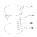
そこで配合する水を計量するための計量容器としては、例えば、図8に示すような簡易水量計が多く用いられている。この簡易水量計101は、有底の円筒形状の容器本体102の側面に取っ手103が設けられると共に、容器本体102の側面には水量目盛104が付されている。
Therefore, as a measuring container for measuring water to be blended, for example, a simple water meter as shown in FIG. 8 is often used. This
しかしながら、この簡易水量計101による水の計量を、工事現場において行う場合には、作業者が取っ手103を持ち、水を入れた容器本体102を目線の位置まで持ち上げた状態で計量を行ったり、また凹凸面や傾斜地面に容器本体102を置いて水の計量を行ったりすることが多く、容器本体102を水平状に保つことが困難であるため、正確な計量を行い難いという問題があった。
また、マンホール蓋の取替え工事は、交通量の少ない夜間に行われることが多く、充分な照明が得られないため、水量目盛104に水位を合せるのが難しく、正確な計量を行い難いと言う問題もあった。
However, when the water is measured by the
In addition, manhole cover replacement work is often done at night when traffic is low, and sufficient lighting cannot be obtained, making it difficult to adjust the water level to the
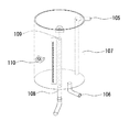
また、正確な水量を計量するための計量容器に関する発明としては、例えば、図9に示すような簡易水量計がある。この簡易水量計は、給水部105と送水部106を備えた水槽107の内部に、上下移動可能に排水管108を配設し、この排水管108の上部に排水口109を設け、この排水口109から排水管108内を通過して水槽107内の水を外部に排出させるような構成とすることにより、排水管108を上下に移動させ、排水口109の高さ位置を水量目盛に合せることによって一定量の水を水槽107内に貯留させることができるというものである(特許文献1参照。)。
Moreover, as invention regarding the measuring container for measuring exact water quantity, there exists a simple water meter as shown, for example in FIG. In this simple water meter, a
しかしながら、特許文献1に記載の簡易水量計は、基台の上に水槽107を設置し、水は外部のタンクから給水部105を通じて供給するものであるため、水量計自体が大掛かりなものとなり、かつ作業現場において持ち運びがし難く、また、作業現場が傾斜面である場合には、水準器110を確認して水槽107が水平になるように調整する必要があるため、マンホール蓋の取り替え作業のように、狭い現場で短時間に、例えば1回の計量のみを必要とする作業においては、非常に手間がかかるとともに、利便性が悪いという問題があった。
However, the simple water meter described in
本発明は、以上の点に鑑みて創案されたものであって、作業現場において簡便且つ正確に計量可能な手持ち用の簡易計量容器を提供することを目的とするものである。 The present invention has been made in view of the above points, and an object of the present invention is to provide a hand-held simple weighing container that can be measured easily and accurately at a work site.
上記の目的を達成するために、本発明に係る手持ち用の簡易計量容器は、所要の水量を計量する手持ち用の簡易計量容器であって、上端が開口した有底の容器本体と、前記容器本体の底部に設けた脚部と、前記容器本体の中心軸線上に、その排水口が位置し、前記排水口から容器本体外に排水させる排水管を備え、前記排水管の前記排水口とは反対側の端部が、前記脚部の接地面よりも前記排水口側に位置すると共に、前記排水管の排水口の高さ位置を設定することにより、所要の水量を前記容器本体内に貯留させる構成とする。 In order to achieve the above object, a hand-held simple measuring container according to the present invention is a hand-held simple measuring container for measuring a required amount of water, the container body having a bottom with an open upper end, and the container. A leg provided at the bottom of the main body, and a drain pipe on the central axis of the container main body, the drain outlet being located and draining the container main body from the drain outlet, and the drain outlet of the drain pipe The opposite end is positioned closer to the drain than the ground contact surface of the leg , and the required water volume is stored in the container body by setting the height of the drain of the drain pipe. The configuration is to be
以上の構成において、セメントモルタルの種類や量に応じてあらかじめ決められた水量となるように高さ位置を設定した排水管の排水口は、容器本体の中心軸線上、すなわち容器本体内に貯留される水面の中心に位置することから、容器本体をどのような状態に傾けても排水口は常に水面の中心に位置し、容器本体内における排水管の排水口の高さ位置までの水を容易、且つ正確に貯留させることが可能となる。 In the above configuration, the drain outlet of the drain pipe whose height is set so as to have a predetermined amount of water according to the type and amount of cement mortar is stored on the central axis of the container body, that is, in the container body. The drain outlet is always located at the center of the water surface regardless of the tilt of the container body, making it easy for water to reach the height of the drain outlet of the drain pipe inside the container body. And it becomes possible to store correctly.
本発明に係る手持ち用の簡易計量容器によれば、作業者は排水口の高さ位置を所要の高さ位置に設定し、計量容器内に水を貯めることにより、余分な水は排水口から排出され、所要の水量が計量容器内に貯留するため、簡便且つ正確に所要の水量を計量することができる。 According to the hand-held simple weighing container according to the present invention, the operator sets the height position of the drainage port to the required height position and stores water in the weighing container, so that excess water can be discharged from the drainage port. Since the required amount of water is discharged and stored in the measuring container, the required amount of water can be measured easily and accurately.
また、排水管は、容器本体の底面中心部から容器本体の中心軸線の上方に向けて立設しているために、現場が傾斜面である場合においても、傾斜面に容器本体を置いたまま、水を貯めるだけで余分な水は容器本体の底面より排水され、所要の水量を計量することができる。さらに、夜間の工事において、容器本体の目盛が見えない場合においても、容器本体に水を貯めるだけで、所要の水量を計量することができる。 In addition, since the drain pipe is erected from the center of the bottom surface of the container body toward the center axis of the container body, the container body remains on the inclined surface even when the site is an inclined surface. By simply storing water, excess water is drained from the bottom of the container body, and the required amount of water can be measured. Furthermore, even when the scale of the container body is not visible during night construction, the required amount of water can be measured simply by storing water in the container body.
また、所要の水量に応じて排水口の高さ位置を調整できるように、排水管を下部排水管と上部排水管とから構成し、上部排水管を所要の水量に応じて交換可能とすることにより、セメントモルタルの種類や量による所要の水量に応じて上部排水管を取替え、所要の水量を計量することができる。 In addition, the drainage pipe is composed of a lower drainage pipe and an upper drainage pipe so that the height position of the drainage can be adjusted according to the required quantity of water, and the upper drainage pipe can be replaced according to the required quantity of water. Thus, it is possible to measure the required amount of water by replacing the upper drainage pipe according to the required amount of water depending on the type and amount of cement mortar.
また、容器本体の外周面に水量目盛を設けたことにより、排水口の高さ位置を水量目盛に合せて設定でき、任意の水量を自在に計量することが可能となる。 Moreover, by providing the water volume scale on the outer peripheral surface of the container main body, the height position of the drain outlet can be set according to the water volume scale, and any amount of water can be freely measured.
また、本発明に係る手持ち用の簡易計量容器においては、排水管は、前記容器本体の底面中心部から前記容器本体の中心軸線の上方に向けて設けた構成とされる。 Further, in the hand-held simple weighing container according to the present invention, the drain pipe is configured to be provided from the center of the bottom surface of the container body toward the upper side of the central axis of the container body.
以上の構成においては、排水管の排水口が容器本体の中心軸線上に位置することになり、所要の水量を容器本体に貯留するとともに、余分な水は排水口より排水管を通して容器本体の底面から排出される。 In the above configuration, the drain outlet of the drain pipe is located on the central axis of the container body, and the required amount of water is stored in the container body, and excess water passes through the drain pipe from the drain outlet to the bottom surface of the container body. Discharged from.
また、本発明に係る手持ち用の簡易計量容器おいては、前記排水管は、前記容器本体に固定される下部排水管と、前記下部排水管に適宜手段により取り付けられる上部排水管とからなり、前記上部排水管は所要の水量に応じて交換可能な構成とされる。 Further, in the hand-held simple weighing container according to the present invention, the drain pipe is composed of a lower drain pipe fixed to the container body and an upper drain pipe attached to the lower drain pipe by appropriate means, The upper drain pipe is configured to be replaceable according to a required amount of water.
以上の構成においては、前記下部排水管に対して、ネジ式、あるいはプッシュ・プル式などの適宜手段により上部排水管を交換可能とすることにより、セメントモルタルの種類や量による所要の水量に応じて、上部排水管を取替え、計量水量を容易に変更することが可能となる。 In the above configuration, the upper drainage pipe can be replaced with an appropriate means such as a screw type or a push-pull type for the lower drainage pipe, so that the required amount of water depending on the type and amount of cement mortar can be used. Thus, it becomes possible to easily change the amount of metered water by replacing the upper drainage pipe.
また、本発明に係る手持ち用の簡易計量容器おいては、前記容器本体の外周面に水量目盛を設け、
前記排水管の排水口の高さ位置を前記水量目盛に合せて調整自在とした構成とされる。
In the hand-held simple weighing container according to the present invention, a water volume scale is provided on the outer peripheral surface of the container body,
The height position of the drain outlet of the drain pipe is configured to be adjustable according to the water volume scale.
以上の構成においては、下部排水管に対して上下動自在なスライド方式などの適宜手段により排水管の排水口の高さ位置を自在に調整できる機構とすることにより、容器本体の外周面に設けた水量目盛に排水口の高さ位置を合せることで、容器本体に貯留する水量を自在に調整することが可能となる。 In the above configuration, a mechanism that can freely adjust the height position of the drain outlet of the drain pipe by an appropriate means such as a slide system that can move up and down with respect to the lower drain pipe is provided on the outer peripheral surface of the container body. The amount of water stored in the container body can be freely adjusted by aligning the height position of the drain outlet with the water volume scale.
以下、本発明の実施例を図面を参酌しながら説明し、本発明の理解に供する。
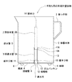
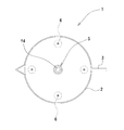
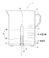
図1は、本発明を適用した手持ち用の簡易計量容器の一例を示す断面側面図、図2は、図1における平面説明図である。
In the following, embodiments of the present invention will be described with reference to the drawings for understanding of the present invention.
FIG. 1 is a cross-sectional side view showing an example of a hand-held simple weighing container to which the present invention is applied, and FIG. 2 is an explanatory plan view of FIG.
図1において透明状のプラスチック素材により形成される手持ち用の簡易計量容器1は、有底円筒形状の容器本体2と、この容器本体2の外周面に突設される取っ手部3と、容器本体2の底面4の中心部から軸線の上方に向けて立設した排水管5とから構成されている。
In FIG. 1, a hand-held
容器本体2は、その底面4に脚部6が90°の間隔を置いて4箇所(図2参照)に設けられ、底面4と脚部6の接地面との間に空隙が形成されている。これにより、容器本体2から外部への排水が支障なく行えるようになっている。また、容器本体2の底面4の中心部に排水穴7が貫設される。この排水穴7には、容器本体2と排水管5とを連結する連結管9が挿入される。この連結管9は、その略上半分に外径が排水穴7の内径とほぼ同一の雄ネジ部11が形成され、下端には鍔状の係留部12が周設される。
The
このような連結管9が容器本体2の底面から排水穴7内に挿通され、連結管9の下端の係留部12が排水穴7の周縁部に係留し、雄ネジ部11が容器本体2の底面4の中心部より突出した状態となり、この雄ネジ部11に排水管5の下端に形成した雌ネジ部10を螺合させ、排水管5と容器本体2とが連結固定される。なお、排水管5の下端面と容器本体2との間には、環状のゴムパッキン13を介在させており、排水管5の下端面を容器本体2に圧接することにより排水穴7からの水漏れを防止できる構成とされている。
Such a connecting
また、本実施例においては、排水管5は、連結管9を介して容器本体2に連結固定される下部排水管5Aと、下部排水管5Aに対して適宜手段により取り替え自在とされる上部排水管5Bとから構成されている。この上部排水管5Bは、その下端に形成した雄ネジ部11Aが、ゴムパッキン13を介して、下部排水管5Aの上端に形成した雌ネジ10Aに螺合連結できる構成とされている。
なお、市販されているセメントモルタルは、その種類によって配合する水量が異なるため、これに適応できるように、工事現場においては、長さの異なる上部排水管5Bを予め準備しておく。
In this embodiment, the
In addition, since commercially available cement mortar has a different amount of water depending on the type, an
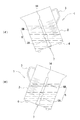
ここで、上部排水管5Bの排水口14は図2に示すように、容器本体2の軸線上に位置することとなる。すなわち、図3(イ)、(ロ)にそれぞれ示すように、容器本体2をどのような角度に傾けた場合でも、上部排水管5Bの排水口14は、容器本体2内に貯留する水の水面の中心部に位置するため、容器本体2を水平面に置いた場合と同じ量の水が余分な水として排水口14から排水され、一方、所要の水量が容器本体2内に溜まることとなり、簡便且つ正確に、所要の水量を計量することができる。
Here, the
次に、本発明を適用した他の実施例について説明する。下部排水管5Aと上部排水管5Bとの連結構造としては、図4に示すように、下部排水管5Aの上端にゴムパッキン13を装着した凹状ソケット部15を形成し、上部排水管5Bの下端に凸状ソケット部16を形成し、下部排水管5Aの凹状ソケット部15内に上部排水管5Bの凸状ソケット部16を嵌入することにより、下部排水管5Aと上部排水管5Bとをプッシュ・プル式で着脱自在な連結機構とすることもできる。
Next, another embodiment to which the present invention is applied will be described. As shown in FIG. 4, the connecting structure of the
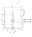
また、図5に示すように、下部排水管5Aに対して上部排水管5Bを上下動自在な状態で外挿するとともに、上部排水管5Bの下端に左右方向へ回すことにより下部排水管5Aの外周面への締め付け固定、あるいは緩めることができ、上部排水管5Bの高さ位置を自在に調整することができるリング状の係着部17を設けた機構とすることもできる。この構成によれば、容器本体2の外周面に水量目盛18を設け、上部排水管5Bの排水口14の高さ位置を、水量目盛18に合わせて調整することで任意に計量する水量を設定することができる。
Further, as shown in FIG. 5, the
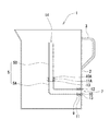
次に、図6は本発明を適用した手持ち用の簡易計量容器の排水管の他の実施例を示す断面側面図である。上部排水管5Bは、排水口14が容器本体2内の軸線上に位置し、そこから垂直下方に延出させ、その下端に形成した雄ネジ部11Aが、ゴムパッキン13を介して、下部排水管5Aの上端に形成した雌ネジ部10Aに螺合連結され、下部排水管5Aは、途中で略直角状に折り曲げられて、容器本体2の外周面に連結固定されている。なお、この下部排水管5Aは、連結管9が容器本体2の外周面に形成した排水穴7内に挿通され、連結管9の雄ネジ部11に下部排水管5Aの一端に形成した雌ネジ部10が螺合により連結固定されている。この場合に下部排水管5Aの端面に環状のゴムパッキン13を介在させ、容器本体2の外周壁内面に圧接することにより、排水穴7からの水漏れを防止できる構成とされている。
Next, FIG. 6 is a sectional side view showing another embodiment of the drain pipe of the hand-held simple weighing container to which the present invention is applied. In the
この場合には、排水穴7が容器本体2の外周面に開口されることとなるために、図1で示すような脚部6が不要となり、部品点数の少ない手持ち用の簡易計量容器の製作が可能とされる。
In this case, since the
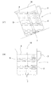
以上、実施例に基づいて本発明に係る手持ち用の簡易計量容器について説明したが、本発明に係る手持ち用の簡易計量容器では、図7(イ)で示すように、例えば工事現場が傾斜地の場合、容器本体2は傾いた状態で給水が行われる。そこで排水口14を超えて供給される水は排水口14より排水管5内を通して容器本体2の底面4に開口される排水穴7より容器本体2の外部へ排水されて排水口14まで水位が下がることになる。
Having described the simple weighing container for hand-held according to the present invention with reference to Examples, in simple weighing container for hand-held according to the present invention, as shown in Figure 7 (b), for example, construction site slopes In this case, water supply is performed with the
ここで、どのような傾斜角度であっても容器本体2内の水面Aの中心部における底面4の中心部からの高さは常に一定であり、この中心部位置に排水管5の排水口14が位置することから、図7(ロ)で示すように傾斜した状態から水平状とした場合には排水口14の高さ位置における水量が貯留されることとなる。
Here, the height from the center portion of the bottom surface 4 in the center portion of the water surface A in the
したがって、例えば市販されているセメントモルタルの種類や量に応じた水量が計量できるように、数種類の高さの異なる上部排水管5Bを予め準備しておくことにより、容易に任意の水量を計量することができる。
Therefore, for example, an arbitrary amount of water can be easily measured by preparing several
また、高さ調整が自在にできる上部排水管5Bにあっては、容器本体2に設けた水量目盛18に排水口14の高さ位置を合せることにより、自在に水量を計量することが可能となる。
In addition, in the
なお、本発明は本実施例の構成に限定されるものではない。例えば、本実施例で前述した容器本体は円筒形状であるが、必ずしも円筒形状に限定されるものではなく、排水口が容器本体の軸線上に位置し、軸線に対して左右対称の形状であればいかなる形状であっても構わない。 In addition, this invention is not limited to the structure of a present Example. For example, the container body described above in the present embodiment has a cylindrical shape, but is not necessarily limited to a cylindrical shape, and the drain port is located on the axis of the container body and is symmetric with respect to the axis. Any shape can be used.
なお、本実施例で前述した下部排水管5Aは、ネジ式の連結管9を介して容器本体2に連結固定するものであるが、必ずしもこれに限定されるものではなく、例えばプラスチックなどにより手持ち用の簡易計量容器を形成する際に、固定一体成形した機構であっても構わない。
The
また、本実施例ではマンホール蓋の取替え作業において使用するセメントモルタルへ配合する水量の計量について説明したが、用途は、必ずしもこれに限定されるものではなく、他の材料における配合水量の計量や、水以外の他の液体の計量等にも活用できるものである。 Further, in this example, the measurement of the amount of water to be blended into the cement mortar used in the manhole cover replacement operation has been described, but the application is not necessarily limited to this, the measurement of the amount of blended water in other materials, It can also be used to measure liquids other than water.
1 手持ち用の簡易計量容器
2 容器本体
3 取っ手部
4 底面
5 排水管
5A 下部排水管
5B 上部排水管
6 脚部
7 排水穴
8 ネジ
9 連結管
10、10A 雌ネジ部
11、11A 雄ネジ部
12 係留部
13 ゴムパッキン
14 排水口
15 凹状ソケット部
16 凸状ソケット部
17 係着部
18 水量目盛
1 Handheld
Claims (4)
上端が開口した有底の容器本体と、
前記容器本体の底部に設けた脚部と、
前記容器本体の中心軸線上に、その排水口が位置し、前記排水口から容器本体外に排水させる排水管を備え、
前記排水管の前記排水口とは反対側の端部が、前記脚部の接地面よりも前記排水口側に位置すると共に、
前記排水管の排水口の高さ位置を設定することにより、所要の水量を前記容器本体内に貯留させる
ことを特徴とする手持ち用の簡易計量容器。 A hand-held simple measuring container for measuring the required amount of water,
A bottomed container body with an open top;
Legs provided at the bottom of the container body;
On the central axis of the container main body, the drain outlet is located, and includes a drain pipe that drains the container main body from the drain outlet ,
The end of the drain pipe opposite to the drain outlet is located closer to the drain outlet than the ground contact surface of the leg,
A hand-held simple weighing container, wherein a required amount of water is stored in the container body by setting a height position of a drain outlet of the drain pipe.
請求項1記載の手持ち用の簡易計量容器。 The handheld simple weighing container according to claim 1, wherein the drainage pipe is erected from the center of the bottom surface of the container body toward the upper side of the central axis of the container body.
請求項1または2記載の手持ち用の簡易計量容器。 The drainage pipe includes a lower drainage pipe fixed to the container main body and an upper drainage pipe attached to the lower drainage pipe by appropriate means, and the upper drainage pipe is replaceable according to a required amount of water. A hand-held simple weighing container according to 1 or 2.
前記排水管の排水口の高さ位置を前記水量目盛に合せて調整自在とした
請求項1〜3の何れか1項に記載の手持ち用の簡易計量容器。 Provide a water scale on the outer peripheral surface of the container body,
The handheld simple measuring container according to any one of claims 1 to 3, wherein a height position of a drain outlet of the drain pipe is adjustable in accordance with the water scale.
Priority Applications (1)
| Application Number | Priority Date | Filing Date | Title |
|---|---|---|---|
| JP2006312339A JP4934412B2 (en) | 2006-11-20 | 2006-11-20 | Simple weighing container for hand-held |
Applications Claiming Priority (1)
| Application Number | Priority Date | Filing Date | Title |
|---|---|---|---|
| JP2006312339A JP4934412B2 (en) | 2006-11-20 | 2006-11-20 | Simple weighing container for hand-held |
Publications (3)
| Publication Number | Publication Date |
|---|---|
| JP2008128748A JP2008128748A (en) | 2008-06-05 |
| JP2008128748A5 JP2008128748A5 (en) | 2009-12-17 |
| JP4934412B2 true JP4934412B2 (en) | 2012-05-16 |
Family
ID=39554728
Family Applications (1)
| Application Number | Title | Priority Date | Filing Date |
|---|---|---|---|
| JP2006312339A Expired - Fee Related JP4934412B2 (en) | 2006-11-20 | 2006-11-20 | Simple weighing container for hand-held |
Country Status (1)
| Country | Link |
|---|---|
| JP (1) | JP4934412B2 (en) |
Families Citing this family (1)
| Publication number | Priority date | Publication date | Assignee | Title |
|---|---|---|---|---|
| JP7463175B2 (en) * | 2020-04-08 | 2024-04-08 | 株式会社クボタ | Liquid Supply Unit |
Family Cites Families (5)
| Publication number | Priority date | Publication date | Assignee | Title |
|---|---|---|---|---|
| FR2242392B1 (en) * | 1973-08-30 | 1979-10-19 | Labaz | |
| US3919177A (en) * | 1973-11-19 | 1975-11-11 | Phillips Petroleum Co | P-phenylene sulfide polymers |
| JPH0685237B2 (en) * | 1984-03-16 | 1994-10-26 | シャープ株式会社 | Method of manufacturing magneto-optical memory device |
| JPS61160022A (en) * | 1985-01-08 | 1986-07-19 | Matsushita Electric Ind Co Ltd | Measuring cup |
| JP3212281B2 (en) * | 1998-06-16 | 2001-09-25 | 岡三機工株式会社 | Simple water meter |
-
2006
- 2006-11-20 JP JP2006312339A patent/JP4934412B2/en not_active Expired - Fee Related
Also Published As
| Publication number | Publication date |
|---|---|
| JP2008128748A (en) | 2008-06-05 |
Similar Documents
| Publication | Publication Date | Title |
|---|---|---|
| US6269495B1 (en) | Adjustable floor drain apparatus | |
| US20080168727A1 (en) | Drain installation system and method | |
| CN205643080U (en) | Concrete slump detection device | |
| JP4934412B2 (en) | Simple weighing container for hand-held | |
| CN208727413U (en) | A kind of agitator tank with measurement function | |
| JP3212281B2 (en) | Simple water meter | |
| US6393908B1 (en) | Outflow meter | |
| CN104713523B (en) | A kind of liquid-level type settlement observation auxiliary device and using method | |
| AU2008207462B2 (en) | A water tank level indicator | |
| CA3010280C (en) | Valve assembly capable of indicating depth | |
| RU2215268C2 (en) | Facility for volume metering | |
| KR100538463B1 (en) | Additives scale device of batcher plant | |
| CN208606866U (en) | Multi-purpose level gauge detection device | |
| CN210679133U (en) | Device for detecting workability of concrete mixture in stirrer | |
| CN209999471U (en) | simple cement paste preparation device for rapidly determining water-cement ratio | |
| CN217901471U (en) | High-precision measurement sand filling cylinder | |
| CN214374806U (en) | Auxiliary device for concrete slump meter | |
| CN218990276U (en) | An intelligent detection device for pile foundation pile top concrete elevation | |
| CN210315552U (en) | Mud proportion control device for cement mixing pile | |
| KR20140004404A (en) | Multi volume tank prover | |
| CN212620487U (en) | Concrete slump test device | |
| GB2514413A (en) | A liquid level indicator device | |
| CN211978605U (en) | Detection device for highway construction | |
| CN214656899U (en) | Road construction is with irritating sand device | |
| CN217896595U (en) | Sand filling device for detecting compaction degree |
Legal Events
| Date | Code | Title | Description |
|---|---|---|---|
| A521 | Written amendment |
Free format text: JAPANESE INTERMEDIATE CODE: A523 Effective date: 20091102 |
|
| A621 | Written request for application examination |
Free format text: JAPANESE INTERMEDIATE CODE: A621 Effective date: 20091102 |
|
| A977 | Report on retrieval |
Free format text: JAPANESE INTERMEDIATE CODE: A971007 Effective date: 20110805 |
|
| A131 | Notification of reasons for refusal |
Free format text: JAPANESE INTERMEDIATE CODE: A131 Effective date: 20110811 |
|
| A521 | Written amendment |
Free format text: JAPANESE INTERMEDIATE CODE: A523 Effective date: 20111006 |
|
| A131 | Notification of reasons for refusal |
Free format text: JAPANESE INTERMEDIATE CODE: A131 Effective date: 20111117 |
|
| A521 | Written amendment |
Free format text: JAPANESE INTERMEDIATE CODE: A523 Effective date: 20120113 |
|
| TRDD | Decision of grant or rejection written | ||
| A01 | Written decision to grant a patent or to grant a registration (utility model) |
Free format text: JAPANESE INTERMEDIATE CODE: A01 Effective date: 20120207 |
|
| A01 | Written decision to grant a patent or to grant a registration (utility model) |
Free format text: JAPANESE INTERMEDIATE CODE: A01 |
|
| A61 | First payment of annual fees (during grant procedure) |
Free format text: JAPANESE INTERMEDIATE CODE: A61 Effective date: 20120220 |
|
| R150 | Certificate of patent or registration of utility model |
Ref document number: 4934412 Country of ref document: JP Free format text: JAPANESE INTERMEDIATE CODE: R150 Free format text: JAPANESE INTERMEDIATE CODE: R150 |
|
| FPAY | Renewal fee payment (event date is renewal date of database) |
Free format text: PAYMENT UNTIL: 20150224 Year of fee payment: 3 |
|
| R250 | Receipt of annual fees |
Free format text: JAPANESE INTERMEDIATE CODE: R250 |
|
| R250 | Receipt of annual fees |
Free format text: JAPANESE INTERMEDIATE CODE: R250 |
|
| S531 | Written request for registration of change of domicile |
Free format text: JAPANESE INTERMEDIATE CODE: R313531 |
|
| R350 | Written notification of registration of transfer |
Free format text: JAPANESE INTERMEDIATE CODE: R350 |
|
| R250 | Receipt of annual fees |
Free format text: JAPANESE INTERMEDIATE CODE: R250 |
|
| R250 | Receipt of annual fees |
Free format text: JAPANESE INTERMEDIATE CODE: R250 |
|
| LAPS | Cancellation because of no payment of annual fees |