JP4933907B2 - Molding apparatus and molding method - Google Patents
Molding apparatus and molding method Download PDFInfo
- Publication number
- JP4933907B2 JP4933907B2 JP2007012680A JP2007012680A JP4933907B2 JP 4933907 B2 JP4933907 B2 JP 4933907B2 JP 2007012680 A JP2007012680 A JP 2007012680A JP 2007012680 A JP2007012680 A JP 2007012680A JP 4933907 B2 JP4933907 B2 JP 4933907B2
- Authority
- JP
- Japan
- Prior art keywords
- molding
- mold
- base material
- plate portion
- skin layer
- Prior art date
- Legal status (The legal status is an assumption and is not a legal conclusion. Google has not performed a legal analysis and makes no representation as to the accuracy of the status listed.)
- Active
Links
- 238000000465 moulding Methods 0.000 title claims description 178
- 238000000034 method Methods 0.000 title claims description 10
- 239000000463 material Substances 0.000 claims description 123
- 229920005989 resin Polymers 0.000 claims description 60
- 239000011347 resin Substances 0.000 claims description 60
- 239000006261 foam material Substances 0.000 claims description 26
- 239000000758 substrate Substances 0.000 claims description 15
- 238000005187 foaming Methods 0.000 claims description 4
- 229920001971 elastomer Polymers 0.000 description 50
- 239000000806 elastomer Substances 0.000 description 50
- 238000007493 shaping process Methods 0.000 description 9
- 239000006260 foam Substances 0.000 description 6
- 238000011144 upstream manufacturing Methods 0.000 description 5
- 230000002093 peripheral effect Effects 0.000 description 3
- UIIMBOGNXHQVGW-UHFFFAOYSA-M Sodium bicarbonate Chemical compound [Na+].OC([O-])=O UIIMBOGNXHQVGW-UHFFFAOYSA-M 0.000 description 2
- 238000010586 diagram Methods 0.000 description 2
- 239000004088 foaming agent Substances 0.000 description 2
- -1 polypropylene Polymers 0.000 description 2
- 239000007787 solid Substances 0.000 description 2
- 239000004743 Polypropylene Substances 0.000 description 1
- 238000013459 approach Methods 0.000 description 1
- 238000004891 communication Methods 0.000 description 1
- 238000002347 injection Methods 0.000 description 1
- 239000007924 injection Substances 0.000 description 1
- 238000001746 injection moulding Methods 0.000 description 1
- 150000002484 inorganic compounds Chemical class 0.000 description 1
- 229910010272 inorganic material Inorganic materials 0.000 description 1
- 230000013011 mating Effects 0.000 description 1
- 150000002894 organic compounds Chemical class 0.000 description 1
- 229920001155 polypropylene Polymers 0.000 description 1
- 229910000030 sodium bicarbonate Inorganic materials 0.000 description 1
- 235000017557 sodium bicarbonate Nutrition 0.000 description 1
- 125000003011 styrenyl group Chemical group [H]\C(*)=C(/[H])C1=C([H])C([H])=C([H])C([H])=C1[H] 0.000 description 1
- 230000037303 wrinkles Effects 0.000 description 1
Images


Landscapes
- Moulds For Moulding Plastics Or The Like (AREA)
- Injection Moulding Of Plastics Or The Like (AREA)
Description
本発明は、基材にクッション層及び表皮層が積層された成形品を成形する際に用いられる成形装置及び成形方法に関する。 The present invention relates to a molding apparatus and a molding method used when molding a molded article in which a cushion layer and a skin layer are laminated on a base material.
従来より、この種の成形装置として、例えば、特許文献1に開示されているように、1つの可動型と、基材成形用及び表皮層成形用の2つの固定型との合計3つの成形型を備えたものが知られている。この成形装置を用いて成形品を成形する際には、まず、基材成形用の固定型と可動型とを型閉じして形成されたキャビティに、基材を構成する樹脂を供給して基材を成形する。その後、型開きして、基材成形用の固定型を、表皮層成形用の固定型と入れ替える。そして、型閉じした後、発泡材料をキャビティにおける基材の表面側に供給する。このとき、可動型を表皮層成形用の固定型から離れる方向に移動させることで、発泡材料は、表皮層成形用の固定型の成形面に接触している部分が発泡せずにソリッド状態となって表皮層となる一方、この表皮層と基材との間の部分は発泡してクッション層となる。
ところで、特許文献1の成形装置では、固定型を基材成形用と表皮層成形用の2つ用意して、基材の成形時と表皮層の成形時とで入れ替えるようにしている。このため、型費が高騰するとともに、成形サイクル毎に固定型を入れ替える時間が必要になって成形サイクルが長くなり、ひいては、成形品のコスト高を招く。
By the way, in the shaping | molding apparatus of
また、基材にクッション層及び表皮層が積層された成形品においては、基材の縁部が裏側へ向けて突出する形状の縦板部とされる場合があり、この場合には、外観見栄えの点から、少なくとも表皮層を縦板部に亘るように形成することが要求される。 In addition, in a molded product in which a cushion layer and a skin layer are laminated on a base material, the edge of the base material may be a vertical plate portion that protrudes toward the back side. From this point, it is required to form at least the skin layer so as to extend over the vertical plate portion.
本発明は斯かる点に鑑みてなされたものであり、その目的とするところは、成形型の数を少なくして型費の低減及び成形サイクルの短縮を図りながら、基材が有する縦板部にも表皮層を形成できるようにして、低コストでかつ外観見栄えの良好な成形品を得ることができるようにすることにある。 The present invention has been made in view of such a point, and the object of the present invention is to reduce the cost of the mold and shorten the molding cycle by reducing the number of molds, and the vertical plate portion of the base material. Another object is to make it possible to form a skin layer so as to obtain a molded product having a low cost and a good appearance.
上記目的を達成するために、請求項1の発明では、クッション層と表皮層が積層された基材の縁部が裏側へ向けて突出する縦板部とされ、該縦板部に少なくとも上記表皮層が積層された成形品を成形する成形装置であって、上記成形品の表面側を成形する第1成形面を有する第1成形型と、上記第1成形面と共にキャビティを構成し、上記成形品の裏面側を成形する第2成形面を有する第2成形型と、上記第1成形型と上記第2成形型の一方を他方に対し接離させる成形型駆動装置と、上記基材を構成する樹脂を上記キャビティに供給する基材用材料供給装置と、上記クッション層及び表皮層を構成する発泡材料を上記キャビティの第1成形面側に供給する発泡材料供給装置と、上記第2成形型における上記基材の縦板部を成形する箇所に、上記キャビティの内外方向に移動するように配置されたスライド型と、上記スライド型を、基材成形位置と、該基材成形位置からキャビティ外方へ向けて移動させた表皮層成形位置との少なくとも一方とするスライド型駆動装置と、上記基材用材料供給装置、上記発泡材料供給装置、上記成形型駆動装置及び上記スライド型駆動装置を制御する制御装置とを備え、上記制御装置は、上記スライド型駆動装置により上記スライド型を基材成形位置とし、上記基材用材料供給装置を作動させた後、上記成形型駆動装置により一方の成形型を他方の成形型から離し、かつ、上記発泡材料供給装置を作動させるとともに、上記スライド型駆動装置により上記スライド型を表皮層成形位置にするように構成されているものとする。 In order to achieve the above object, according to the first aspect of the present invention, the edge of the base material on which the cushion layer and the skin layer are laminated is a vertical plate portion protruding toward the back side, and at least the skin is provided on the vertical plate portion. A molding apparatus for molding a molded product in which layers are laminated, the first molding die having a first molding surface for molding the surface side of the molded product, and a cavity together with the first molding surface, and the molding A second molding die having a second molding surface for molding the back side of the product, a molding die driving device for bringing one of the first molding die and the second molding die into contact with and away from each other, and the base material A base material supply device for supplying resin to the cavity, a foam material supply device for supplying the foam material constituting the cushion layer and the skin layer to the first molding surface side of the cavity, and the second mold In the place where the vertical plate portion of the base material is molded, At least a slide mold arranged to move in and out of the cavity; a base material molding position; and a skin layer molding position in which the slide mold is moved from the base material molding position toward the outside of the cavity. A slide-type drive device, and a base material supply device, the foam material supply device, the molding drive device, and a control device that controls the slide-type drive device. After the slide mold is set to the base material molding position by the mold driving device and the base material supply device is operated, one molding die is separated from the other molding die by the molding die driving device, and the foam material It is assumed that the supply device is operated and the slide die is set to the skin layer forming position by the slide drive device.
この構成によれば、基材用材料供給装置の作動により供給された樹脂は、第1及び第2成形面により基材の形状に成形される。基材用材料供給装置の作動後に、スライド型がキャビティ外方へ移動すると、そのスライド型のキャビティ外方への移動量に対応して、キャビティには、基材の縦板部に対応する部位に未充填空間が生じることになる。そして、発泡材料供給装置の作動によりキャビティに供給された発泡材料は、上記キャビティの縦板部に対応する部位に生じている未充填空間に容易に入り込む。つまり、基材を構成する樹脂は成形直後で十分に固化していないので、発泡材料の供給圧力により基材を構成する樹脂が変形して発泡材料が基材の表面側を流れていき、この発泡材料が第1成形面により成形されて表皮層となる。このとき、基材の縦板部の表面側にも発泡材料を行き渡らせることが可能になり、この発泡材料が第1成形面により成形されて縦板部を覆う表皮層となる。また、発泡材料を供給する際、一方の成形型が他方の成形型から離れるので、発泡材料は、表皮層と基材との間の部分が発泡してクッション層となる。 According to this configuration, the resin supplied by the operation of the substrate material supply device is molded into the shape of the substrate by the first and second molding surfaces. When the slide mold moves to the outside of the cavity after the operation of the substrate material supply device, the cavity corresponds to the amount of movement of the slide mold to the outside of the cavity, and the cavity corresponds to the vertical plate portion of the substrate. An unfilled space is generated in Then, the foam material supplied to the cavity by the operation of the foam material supply apparatus easily enters the unfilled space generated in the portion corresponding to the vertical plate portion of the cavity. In other words, since the resin constituting the base material is not sufficiently solidified immediately after molding, the resin constituting the base material is deformed by the supply pressure of the foam material, and the foam material flows on the surface side of the base material. The foam material is molded by the first molding surface to become a skin layer. At this time, it is possible to spread the foam material also on the surface side of the vertical plate portion of the base material, and this foam material is formed by the first molding surface to become a skin layer covering the vertical plate portion. Further, when the foam material is supplied, one mold is separated from the other mold, so that the foam material foams at a portion between the skin layer and the base material to become a cushion layer.
以上のようにして、クッション層と表皮層が基材に積層され、かつ、基材の縦板部に表皮層が形成された成形品が得られる。 As described above, a molded article in which the cushion layer and the skin layer are laminated on the base material and the skin layer is formed on the vertical plate portion of the base material is obtained.
請求項2の発明では、請求項1の発明において、第1成形面及び第2成形面は、基材の縦板部の基端側の肉厚を該基材の他の部位に比べて厚くするように形状設定されている構成とする。
In the invention of
この構成によれば、基材の成形時、肉厚が相対的に厚い縦板部の基端側においては樹脂が固化し難くなる。これにより、発泡材料をキャビティに供給した際に、発泡材料の供給圧力が低くても縦板部を構成する樹脂を容易に変形させることが可能になり、縦板部の表面側に発泡材料を十分に行き亘らせて表皮層を形成することが可能になる。 According to this structure, at the time of shaping | molding of a base material, it becomes difficult to solidify resin in the base end side of the longitudinally thick board part. As a result, when the foam material is supplied to the cavity, the resin constituting the vertical plate portion can be easily deformed even if the supply pressure of the foam material is low, and the foam material is placed on the surface side of the vertical plate portion. It is possible to form a skin layer with sufficient spread.
請求項3の発明では、クッション層と表皮層が積層された基材の縁部が裏側へ向けて突出する縦板部とされ、該縦板部に少なくとも上記表皮層が積層された成形品を成形する成形方法であって、上記成形品の表面側を成形する第1成形面を有する第1成形型と、上記成形品の裏面側を成形する第2成形面を有する第2成形型とを接近させてキャビティを構成するとともに、これら第1及び第2成形面の間に、上記基材を構成する樹脂を供給して基材を得る第1材料供給工程と、上記基材を構成する樹脂を供給した後に、上記第1成形型と第2成形型とを離すとともに、上記第2成形型における上記縦板部を成形する箇所に配置されたスライド型をキャビティ外方へ移動させる型移動工程と、上記第1成形型と第2成形型とを離し始めた後に、上記表皮層及びクッション層を構成する発泡材料を、上記キャビティの第1成形面側に供給する第2材料供給工程とを備える構成とする。 According to a third aspect of the present invention, there is provided a molded product in which the edge portion of the base material on which the cushion layer and the skin layer are laminated is a vertical plate portion protruding toward the back side, and at least the skin layer is laminated on the vertical plate portion. A molding method for molding, comprising: a first molding die having a first molding surface for molding the front surface side of the molded product; and a second molding die having a second molding surface for molding the back surface side of the molded product. A first material supplying step for obtaining a base material by supplying a resin that constitutes the base material between the first and second molding surfaces, and a resin that constitutes the base material. After moving the mold, the first mold and the second mold are separated from each other, and a mold moving step of moving the slide mold disposed at the position where the vertical plate portion of the second mold is molded to the outside of the cavity is performed. And after starting to separate the first mold and the second mold, The foamed material constituting the serial skin layer and the cushion layer, a configuration and a second material supplying step of supplying the first molding surface side of the cavity.
この構成によれば、第1材料供給工程で供給された樹脂は、第1及び第2成形面により基材の形状に成形される。そして、型移動工程でスライド型をキャビティ外方へ移動させると、その移動量に対応して、キャビティには、基材の縦板部に対応する部位に未充填空間が生じることになる。続く第2材料供給工程で発泡材料をキャビティに供給することにより、請求項1の発明と同様に、発泡材料は、キャビティの縦板部に対応する部位に生じている未充填空間に容易に入り込むので、縦板部に表皮層を形成することが可能になる。また、発泡材料を供給する際、一方の成形型が他方の成形型から離れるので、発泡材料は表皮層と基材との間の部分が発泡してクッション層となる。よって、クッション層と表皮層が基材に積層され、かつ、基材の縦板部に表皮層が形成された成形品が得られる。 According to this configuration, the resin supplied in the first material supply step is molded into the shape of the base material by the first and second molding surfaces. When the slide mold is moved outside the cavity in the mold moving process, an unfilled space is generated in the cavity at a portion corresponding to the vertical plate portion of the base material corresponding to the amount of movement. By supplying the foam material to the cavity in the subsequent second material supply step, the foam material can easily enter the unfilled space generated in the portion corresponding to the vertical plate portion of the cavity, as in the first aspect of the invention. Therefore, it is possible to form a skin layer on the vertical plate portion. Further, when supplying the foamed material, one mold is separated from the other mold, so that the foamed material foams at a portion between the skin layer and the base material to become a cushion layer. Therefore, a molded product in which the cushion layer and the skin layer are laminated on the base material and the skin layer is formed on the vertical plate portion of the base material is obtained.
請求項1の発明によれば、成形品の表面側を成形する第1成形型と裏面側を成形する第2成形型との一方を他方に接離させる型駆動装置を設け、キャビティに基材用材料供給装置により樹脂を供給するととともに、このキャビティの第1成形面側に発泡材料供給装置により発泡材料を供給するようにしたので、第1及び第2成形型を他の成形型に入れ変えることなく、基材にクッション層及び表皮層が積層された成形品を成形できる。そして、第2成形型における基材の縦板部を成形する箇所にスライド型を配設し、このスライド型をキャビティの内外方向に移動させるようにしたので、基材の縦板部の表面側に発泡材料を行き渡らせることができ、該縦板部に表皮層を形成することができる。これにより、見栄えが良好でかつ低コストな成形品を得ることができる。 According to the first aspect of the present invention, the mold driving device for bringing one of the first mold for molding the front side of the molded product and the second mold for molding the back side into the other is provided, and the base material is provided in the cavity. Since the resin is supplied by the material supply device and the foam material is supplied by the foam material supply device to the first molding surface side of the cavity, the first and second molding dies are replaced with other molding dies. The molded product in which the cushion layer and the skin layer are laminated on the substrate can be molded without any problem. Since the slide mold is disposed at the location where the vertical plate portion of the base material in the second mold is formed, and this slide die is moved in and out of the cavity, the surface side of the vertical plate portion of the base material The foamed material can be spread over and the skin layer can be formed on the vertical plate portion. Thereby, a good-looking and low-cost molded product can be obtained.
請求項2の発明によれば、成形時に、基材の縦板部の基端側の肉厚が該基材の他の部位に比べて厚くなって固化し難くなるので、発泡材料の供給圧力が低くても、縦板部の表面側に表皮層を確実に形成することができ、見栄えを良好にすることができる。 According to the second aspect of the present invention, at the time of molding, the thickness of the base end side of the vertical plate portion of the base material is thicker than other parts of the base material and is difficult to solidify. Even if it is low, the skin layer can be reliably formed on the surface side of the vertical plate portion, and the appearance can be improved.
請求項3の発明によれば、第1及び第2成形型を他の成形型に入れ変えることなく、基材にクッション層及び表皮層が積層された成形品を成形できる。そして、型移動工程において、第2成形型における縦板部を成形する箇所に配設されたスライド型をキャビティ外方へ移動させるようにしたので、請求項1の発明と同様に、基材の縦板部の表面側に発泡材料を行き渡らせて表皮層を形成できる。これにより、見栄えが良好でかつ低コストな成形品を得ることができる。
According to the invention of
以下、本発明の実施形態を図面に基づいて詳細に説明する。尚、以下の好ましい実施形態の説明は、本質的に例示に過ぎず、本発明、その適用物或いはその用途を制限することを意図するものではない。 Hereinafter, embodiments of the present invention will be described in detail with reference to the drawings. It should be noted that the following description of the preferred embodiment is merely illustrative in nature, and is not intended to limit the present invention, its application, or its use.
図1及び図2は、本発明の実施形態に係る成形装置1を示している。この成形装置1は、自動車のドアトリム等に設けられるパネル部材100(図3に示す)を成形する際に用いられるものである。この成形装置1で成形されるパネル部材100は、図3(b)に示すように、基材101と、該基材101の表面側に設けられたクッション層102と、クッション層102の表面側に設けられた表皮層103とで構成されている。基材101は、略平坦な矩形状の平板部101aと、平板部101aの周縁部からパネル部材100の裏側へ向けて突出する環状の縦板部101bとを備えている。縦板部101bの突出方向は、平板部101aに略直交する方向とされている。平板部101aと縦板部101bとは、硬質な樹脂材料を用いて一体成形されている。縦板部101bの基端側は、該縦板部101bの先端側及び上記平板部101aよりも厚肉に形成されている。また、クッション層102は、エラストマーの発泡体で構成され、表皮層103は、ソリッドなエラストマーで構成されている。クッション層102及び表皮層103は、後述する成形時に一体に成形されたものである。クッション層102は、基材101の平板部101a全体と、縦板部101bの基端側の一部とに連続して設けられている。表皮層103は、クッション層102の全体を覆い、かつ、基材101の縦板部101bの先端部近傍までの領域を覆うように設けられている。表皮層103の表面には、全体に亘って細かいシボ模様が形成されている。
1 and 2 show a
図1に示すように、上記成形装置1は、固定型2及び可動型3と、型駆動装置8と、基材101を構成する樹脂を供給する樹脂供給装置9と、エラストマーを供給するエラストマー供給装置10とを備えている。
As shown in FIG. 1, the
上記型駆動装置8は、水平方向に伸縮動作する油圧シリンダー等で構成されている。型駆動装置8のロッド8aが可動型3の左側面(図1及び図2の左側)に連結され、可動型3が図1及び図2の左右方向に水平移動することで、固定型2に対し接離する。
The
上記可動型3には、右側へ膨出するように形成された第1及び第2本体型11、12が成形装置1の奥行き方向(図1及び図2の上下方向)に離れて設けられている。第1及び第2本体型11、12は、同じ形状とされ、左右方向に移動可能に可動型3に支持されている。第1及び第2本体型11、12の右側面が可動側成形面11a、12aとされている。可動側成形面11a、12aは、基材101の平板部101aの裏面側を成形するためのものである。一方、固定型2の左側面は、第1及び第2本体型11、12に対向する部位が右側へ窪むように形成されており、この窪み部分の内面が固定側成形面2a、2aとされている。この固定側成形面2a、2aは、パネル部材100の表面側を成形するためのものである。つまり、本発明の第1成形型は、固定型2で構成され、また、本発明の第2成形型は、第1及び第2本体型11、12で構成されている。また、本発明の第1成形面は、固定側成形面2aで構成され、また、本発明の第2成形面は、可動側成形面11a、12aで構成されている。
The
第1及び第2本体型11、12の左側には、第1及び第2本体型駆動装置13、14が配設されている。第1及び第2本体型駆動装置13、14は、左右方向に伸縮動作する周知の油圧シリンダ等で構成されており、ロッド(図示せず)の先端部が第1及び第2本体型11、12に連結されている。第1及び第2本体型駆動装置13、14は、第1及び第2本体型11、12を左右方向移動させることで、これら本体型11、12を基材成形位置とクッション層成形位置とに切り替えるように構成されている。基材成形位置とは、可動側成形面11a、12aと固定側成形面2a、2aとの隙間が基材101の厚み寸法となる位置であり、クッション層成形位置とは、可動側成形面11a、12aと固定側成形面2a、2aとの隙間が、基材101の厚みとクッション層102の厚みと表皮層103の厚みとを合わせた寸法となる位置である。
On the left side of the first and
上記可動型3と固定型2とを型締めすると、固定側成形面2a、2aと、可動側成形面11a、12aとの間に第1キャビティC1及び第2キャビティC2(図1に示す)が奥行き方向に離れて形成されるようになっている。これらキャビティC1、C2は同じ形状である。詳細は後述するが、上記樹脂供給装置9及びエラストマー供給装置10によって各キャビティC1、C2に供給された樹脂及びエラストマーは、成形されてパネル部材100となる。この固定型2及び可動型3内においては、図9に示すように、パネル部材100は、基材101の平板部101aが略鉛直となり、かつ、縦板部101bが略水平に突出する向きとなっている。
When the
図1に示すように、固定型2と可動型3との合わせ部には、第1キャビティC1に開口する第1ゲート16と、第2キャビティC2に開口する第2ゲート17と、これら両ゲート16、17の間において、成形装置1の奥行き方向に延びるランナー18とが形成されている。このランナー18の両端部は、第1ゲート16及び第2ゲート17にそれぞれ連通している。
As shown in FIG. 1, the mating portion of the fixed
固定型2には、ランナー18に樹脂を流入させるための樹脂通路19と、樹脂通路19を開閉する樹脂流量制御弁20と、ランナー18にエラストマーを流入させるためのエラストマー通路21と、エラストマー通路21を開閉するエラストマー流量制御弁22とが設けられている。樹脂通路19の上流端部は、固定型2の右側面に開口しており、この上流端に樹脂供給装置9のノズル9aが接続されている。樹脂通路19は、上流端部から左側へ延び、下流端部は、ランナー18の長手方向略中央部に連通している。樹脂流量制御弁20は、樹脂通路19の中途部に配置されている。
The fixed
エラストマー通路21の上流側は、成形装置1の奥行き方向に延び、固定型2の端面に開口している。このエラストマー通路21の上流端にエラストマー供給装置10のノズル10aが接続されている。エラストマー通路21の下流側は、2つに分岐しており、これらのうち、一方の通路が、ランナー18の樹脂通路19よりも第1ゲート16に近い側に連通し、他方の通路が、ランナー18の樹脂通路19よりも第2ゲート17に近い側に連通している。つまり、エラストマー通路21の下流側は、第1ゲート16近傍と第2ゲート17近傍とにそれぞれ連通している。エラストマー流量制御弁22は、エラストマー通路21の中途部に配置されている。上記樹脂供給装置9及びエラストマー供給装置10は、従来より周知の射出成形機等で構成されている。
The upstream side of the
上記第1及び第2本体型11、12における基材100の縦板部101bを成形する箇所には、該本体型11、12をそれぞれ囲むように形成された環状の第1及び第2スライド型25、26が配置されている。これらスライド型25、26は、同じ形状とされている。第1及び第2スライド型25、26は、縦板部101bの内周面を成形するためのものであり、縦板部101bの突出方向である左右方向(図5に矢印イで示す)に移動可能に可動型3に支持されている。
In the first and second
上記第1及び第2スライド型25、26の左側には、第1及び第2スライド型駆動装置27、28が配設されている。第1及び第2スライド型駆動装置27、28は、左右方向に伸縮動作する周知の油圧シリンダ等で構成されており、ロッド(図示せず)の先端部が第1及び第2スライド型25、26に連結されている。スライド型駆動装置27、28は、スライド型25、26を左右方向、即ちキャビティC1、C2の内外方向に移動させることで基材成形位置と表皮層成形位置とに切り替えるように構成されている。基材成形位置とは、スライド型25、26の右端部が、基材成形位置にある可動側成形面11a、12aと略同一面上に位置している状態(図5及び図6に示す)であり、表皮層成形位置とは、スライド型25、26の右端部が、基材成形位置にある可動側成形面11aよりも左側に位置している状態(図7に示す)である。
On the left side of the first and second slide dies 25 and 26, first and second
上記各固定側成形面2aは、図5に示すように、可動型成形面11a、12aと略平行に延びる水平面部2bと、水平面部2bの周縁部から左側へ延びる縦面部2cとで構成されている。固定側成形面2a、2aと可動側成形面11a、12aとは、基材100の縦板部101bの基端側の肉厚が基材100の平板部101a及び縦板部101bの先端側の肉厚よりも厚くなるように、形状設定されている。上記各固定側成形面2aの水平面部2b及び縦面部2cには、表皮層103にシボ模様を形成するための微少な凹凸形状が形成されている。
As shown in FIG. 5, each of the fixed-
また、上記成形装置1は、制御装置40を備えている。この制御装置40には、図4に示すように、型駆動装置8、樹脂供給装置9、エラストマー供給装置10、本体型駆動装置13、14、樹脂流量制御弁20、エラストマー流量制御弁22及びスライド型駆動装置27、28が接続されており、これら装置8〜10、13、14、27、28及び流量制御弁20、22を制御するように構成されている。
The
具体的には、制御装置40は、成形開始の信号を受けると、まず、キャビティC1、C2を形成して基材101の成形を開始するように、各装置8〜10、13、14、27、28及び樹脂流量制御弁15に制御信号を送出する。すなわち、図5に示すように、制御装置40は、型駆動装置8により上記固定型2と可動型3とを型閉じする。さらに、第1及び第2本体型駆動装置13、14により第1及び第2本体型11、12を基材成形位置にするとともに、第1及び第2スライド型駆動装置27、28により第1及び第2スライド型25、26を基材成形位置とする。その後、樹脂供給装置9を作動させるとともに、樹脂流量制御弁20を開状態とする。
Specifically, when receiving a molding start signal, the
制御装置40は、基材101を構成する樹脂の供給が終了すると、クッション層102及び表皮層103の成形を開始するように、各装置8〜10、13、14、27、28及び流量制御弁22に制御信号を送出する。すなわち、制御装置40は、樹脂流量制御20を閉状態とした後、図8に示すように、本体型駆動装置13、14により第1及び第2本体型11、12を左側へ移動させ、かつ第1及び第2スライド型駆動装置27、28により第1及び第2スライド型25、26を表皮層成形位置とし、その後、エラストマー供給装置10を作動させるとともに、エラストマー流量制御弁22を開状態とする。可動型3、本体型11、12及びスライド型25、26の移動速度や、樹脂及びエラストマーの供給量及び流速は、制御装置40によって任意の値に制御可能となっている。
When the supply of the resin constituting the
次に、上記のように構成された成形装置1を用いてパネル部材100を成形する要領について説明する。基材101を構成する樹脂は、例えばポリプロピレンを用い、これを樹脂供給装置9に溶融状態で準備しておく。クッション層102及び表皮層103を構成する材料は、例えば上記特許文献1に開示されている発泡性のエラストマー(発泡材料)を用い、これをエラストマー供給装置10に準備しておく。尚、エラストマーとしては、飽和型スチレン系エラストマーが好ましく、これに混入する発泡剤としては、エラストマーを発泡させることができるものであればよく、例えば、重炭酸ナトリウム等の無機化合物やアゾ化合物等の有機化合物のような分解性発泡剤が挙げられる。
Next, the point which shape | molds the
成形開始の信号を制御装置40に送ると、制御装置40は、図1及び図5に示すように、第1及び第2本体型駆動装置13、14により第1及び第2本体型11、12を基材成形位置にし、第1及び第2スライド側駆動装置27、28により第1及び第2スライド型25、26を基材成形位置にする。さらに、型駆動装置8により可動型3と固定型2とを型閉じして型締めする。これにより、第1及び第2キャビティC1、C2が形成される。
When a molding start signal is sent to the
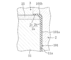
次いで、制御装置40は、樹脂供給装置9を作動させて樹脂の供給を開始するとともに、樹脂流量制御弁20を開放する。これにより、樹脂が樹脂通路19を通ってランナー18に流入する。ランナー18に流入した樹脂は、該ランナー18内を第1ゲート16側及び第2ゲート17側へ流れて第1ゲート16から第1キャビティC1に射出され、第2ゲート17から第2キャビティC2に射出される。第1及び第2キャビティC1、C2に射出された樹脂は、図6に示すように、固定側成形面2a、スライド型25、26の成形面及び可動側成形面11a、12aにより成形されて基材101の形状となる。このとき、縦板部101bの基端側が他の部位に比べて肉厚であるため、樹脂が固化し難くなっている。ここまでが、本発明の第1材料供給工程である。
Next, the
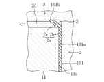
その後、ランナー18内の樹脂及び基材101を構成する樹脂が完全に固化しないうちに、制御装置40は、図7に示すように、第1及び第2スライド型駆動装置27、28により第1及び第2スライド型25、26をキャビティC1、C2の外方(図7に白抜きの矢印で示す方向)へ向けて移動させて表皮層成形位置にする。スライド型25、26がキャビティC1、C2の外方へ移動した分、キャビティC1、C2には、基材101の縦板部101bに対応する部位に未充填空間Sが生じることになる。
Thereafter, before the resin in the
その後、制御装置40は、図8に示すように、第1及び第2本体型駆動装置13、14により第1及び第2本体型11、12を基材101と共に左側(図8に白抜きの矢印で示す方向)へ移動させ、基材101と固定側成形面2aとの間に隙間を形成しておく。このときの第1及び第2本体型11、12の移動量は、表皮層103の厚さ寸法と略同じくらいである。ここまでが、本発明の型移動工程である。
Thereafter, as shown in FIG. 8, the
制御装置40は、第1及び第2本体型11、12の移動と同期して、エラストマー供給装置10を作動させてエラストマーの供給を開始するとともに、エラストマー流量制御弁22を開放する。これにより、エラストマーがエラストマー通路21を通ってランナー18に流入する。このとき、ランナー18内にある基材101用の樹脂は、完全に固化していないので、エラストマー供給装置10による供給圧力で変形し、ランナー18内にエラストマーが流れる通路が形成されていく。ランナー18に流入した樹脂は、該ランナー18内を第1ゲート16側及び第2ゲート17側へ流れて、第1ゲート16から第1キャビティC1の固定側成形面2a側に射出され、第2ゲート17から第2キャビティC2の固定側成形面2a側に射出される。これが、本発明の第2材料供給工程である。キャビティC1、C2に射出されたエラストマーは、基材101を構成する樹脂が完全に固化していないので、エラストマー供給装置10による供給圧力により、基材101の表側を通って第1及び第2キャビティC1、C2の未充填空間Sに容易に入り込む。このとき、図8に示すように、エラストマーの供給圧力により縦板部101bを構成する樹脂が変形し、縦板部101bの表面側にエラストマーが行き渡る。この縦板部101bの表面側に行き亘ったエラストマーは、固定側成形面2aの縦面部2cに接触し、該縦面部2cにより成形されて表皮層103となる。また、基材101の平板部101aの表面側全体にもエラストマーが行き渡り、このエラストマーは、固定側成形面2aの水平面部2bに接触し、該水平面部2bにより成形されて縦板部101bの表皮層103となる。表皮層103には、固定側成形面2aによりシボ模様が転写される。
In synchronization with the movement of the first and second
しかる後、図9に示すように、制御装置40は第1及び第2本体型駆動装置13、14により第1及び第2本体型11、12を左側へ移動させて、クッション層成形位置とする。これにより、表皮層103と基材101との間のエラストマーが安定して発泡し、クッション層102となる。このようにして、クッション層102と表皮層103が基材101に積層され、かつ、基材101の縦板部101bに表皮層103が形成されたパネル部材100が得られる。パネル部材100を脱型する際には、型駆動装置8により可動型3を左側へ移動させて型開きする。
Thereafter, as shown in FIG. 9, the
以上説明したように、この実施形態によれば、固定型2及び可動型3を他の成形型に入れ変えることなく、表皮層103及びクッション層102が基材101に積層されたパネル部材100を成形でき、しかも、縦板部101bに表皮層103を形成できる。これにより、見栄えが良好でかつ低コストなパネル部材100を得ることができる。
As described above, according to this embodiment, the
また、成形時に、基材101の縦板部101bの基端側の肉厚を該基材101の他の部位に比べて厚くしているので、縦板部101bの基端側は固化し難くなっており、これにより、エラストマーの供給圧力が低くても、縦板部101bの表面側にエラストマーを行き渡らせて表皮層103を形成することができる。
Moreover, since the thickness of the base end side of the
尚、基材101を構成する樹脂や、クッション層102及び表皮層103を構成する発泡材料は上記した材料に限られるものではない。
In addition, the resin which comprises the
また、基材101を構成する樹脂の供給タイミングとしては、型閉じ前や型締め前であってもよい。また、クッション層102及び表皮層103を構成するエラストマーの供給タイミングとしては、本体型11、12の移動途中であってもよいし、本体型11、12の移動を停止した後であってもよい。
In addition, the supply timing of the resin constituting the
また、スライド型25、26を基材成形位置から表皮層成形位置まで移動させる途中に、エラストマーの供給を開始してもよい。 Further, the supply of the elastomer may be started while the slide dies 25 and 26 are moved from the base material molding position to the skin layer molding position.
また、成形装置1の構造としては、可動型を下側に配置し、固定型を上側に配置するようにしてもよいし、固定型を下側に配置し、可動型を上側に配置するようにしてもよい。
As the structure of the
以上説明したように、本発明に係る成形装置及び成形方法は、例えば、自動車用の内装材として用いられるパネル部材を成形するのに適している。 As described above, the molding apparatus and molding method according to the present invention are suitable for molding a panel member used as an interior material for automobiles, for example.
1 成形装置
2 固定型(第1成形型)
2a 固定側成形面(第1成形面)
3 可動型
3a 可動側成形面
9 樹脂供給装置(基材用材料供給装置)
10 エラストマー供給装置(発泡材料供給装置)
11 第1本体型(第2成形型)
11a 可動型成形面(第2成形面)
12 第2本体型(第2成形型)
12a 可動側成形面(第2成形面)
13 第1本体型駆動装置(成形型駆動装置)
14 第2本体型駆動装置(成形型駆動装置)
25 第1スライド型
26 第2スライド型
27 第1スライド型駆動装置
28 第2スライド型駆動装置
40 制御装置
100 パネル部材(成形品)
101 基材
101b 縦板部
102 クッション層
103 表皮層
C キャビティ
S 未充填空間
1
2a Fixed side molding surface (first molding surface)
3 movable mold 3a movable
10 Elastomer supply device (foaming material supply device)
11 First body mold (second mold)
11a Movable molding surface (second molding surface)
12 Second body mold (second mold)
12a Movable molding surface (second molding surface)
13 First body type driving device (molding type driving device)
14 Second body type driving device (molding type driving device)
25
101
Claims (3)
上記成形品の表面側を成形する第1成形面を有する第1成形型と、
上記第1成形面と共にキャビティを構成し、上記成形品の裏面側を成形する第2成形面を有する第2成形型と、
上記第1成形型と上記第2成形型の一方を他方に対し接離させる成形型駆動装置と、
上記基材を構成する樹脂を上記キャビティに供給する基材用材料供給装置と、
上記クッション層及び表皮層を構成する発泡材料を上記キャビティの第1成形面側に供給する発泡材料供給装置と、
上記第2成形型における上記基材の縦板部を成形する箇所に、上記キャビティの内外方向に移動するように配置されたスライド型と、
上記スライド型を、基材成形位置と、該基材成形位置からキャビティ外方へ向けて移動させた表皮層成形位置との少なくとも一方とするスライド型駆動装置と、
上記基材用材料供給装置、上記発泡材料供給装置、上記成形型駆動装置及び上記スライド型駆動装置を制御する制御装置とを備え、
上記制御装置は、上記スライド型駆動装置により上記スライド型を基材成形位置とし、上記基材用材料供給装置を作動させた後、上記成形型駆動装置により一方の成形型を他方の成形型から離し、かつ、上記発泡材料供給装置を作動させるとともに、上記スライド型駆動装置により上記スライド型を表皮層成形位置にするように構成されていることを特徴とする成形装置。 A molding apparatus for molding a molded product in which an edge portion of a base material in which a cushion layer and a skin layer are laminated is a vertical plate portion protruding toward the back side, and at least the skin layer is laminated on the vertical plate portion. ,
A first mold having a first molding surface for molding the surface side of the molded article;
A second molding die having a second molding surface that forms a cavity together with the first molding surface and molds the back surface side of the molded product;
A mold driving device for contacting or separating one of the first mold and the second mold with respect to the other;
A substrate material supply device that supplies the resin constituting the substrate to the cavity;
A foam material supply device for supplying the foam material constituting the cushion layer and the skin layer to the first molding surface side of the cavity;
A slide mold disposed so as to move inward and outward of the cavity at a location where the vertical plate portion of the base material in the second molding die is molded;
A slide type driving device having the slide mold as at least one of a base material molding position and a skin layer molding position moved from the base material molding position toward the outside of the cavity;
A control device for controlling the base material supply device, the foam material supply device, the mold drive device, and the slide drive device;
The control device sets the slide mold to a base material molding position by the slide mold driving device, operates the base material supply device, and then moves one molding die from the other molding die by the molding die driving device. The molding apparatus is configured to release the foaming material supply apparatus and to move the slide mold to the skin layer molding position by the slide mold driving apparatus.
第1成形面及び第2成形面は、基材の縦板部の基端側の肉厚を該基材の他の部位に比べて厚くするように形状設定されていることを特徴とする成形装置。 The molding apparatus according to claim 1,
The molding is characterized in that the first molding surface and the second molding surface are set so that the thickness of the base end side of the vertical plate portion of the base material is thicker than other parts of the base material. apparatus.
上記成形品の表面側を成形する第1成形面を有する第1成形型と、上記成形品の裏面側を成形する第2成形面を有する第2成形型とを接近させてキャビティを構成するとともに、これら第1及び第2成形面の間に、上記基材を構成する樹脂を供給して基材を得る第1材料供給工程と、
上記基材を構成する樹脂を供給した後に、上記第1成形型と第2成形型とを離すとともに、上記第2成形型における上記縦板部を成形する箇所に配置されたスライド型をキャビティ外方へ移動させる型移動工程と、
上記第1成形型と第2成形型とを離し始めた後に、上記表皮層及びクッション層を構成する発泡材料を、上記キャビティの第1成形面側に供給する第2材料供給工程とを備えることを特徴とする成形方法。 A molding method for molding a molded product in which an edge portion of a base material on which a cushion layer and a skin layer are laminated is a vertical plate portion protruding toward the back side, and at least the skin layer is laminated on the vertical plate portion. ,
The first molding die having a first molding surface for molding the front surface side of the molded product and the second molding die having a second molding surface for molding the back surface side of the molded product are made close to each other to form a cavity. A first material supplying step for obtaining a base material by supplying a resin constituting the base material between the first and second molding surfaces;
After supplying the resin that constitutes the base material, the first mold and the second mold are separated, and a slide mold disposed at a position where the vertical plate portion of the second mold is molded is disposed outside the cavity. Mold moving process to move toward the direction,
A second material supply step of supplying the foam material constituting the skin layer and the cushion layer to the first molding surface side of the cavity after starting to separate the first mold and the second mold; A molding method characterized by the above.
Priority Applications (1)
| Application Number | Priority Date | Filing Date | Title |
|---|---|---|---|
| JP2007012680A JP4933907B2 (en) | 2007-01-23 | 2007-01-23 | Molding apparatus and molding method |
Applications Claiming Priority (1)
| Application Number | Priority Date | Filing Date | Title |
|---|---|---|---|
| JP2007012680A JP4933907B2 (en) | 2007-01-23 | 2007-01-23 | Molding apparatus and molding method |
Publications (3)
| Publication Number | Publication Date |
|---|---|
| JP2008179002A JP2008179002A (en) | 2008-08-07 |
| JP2008179002A5 JP2008179002A5 (en) | 2010-01-28 |
| JP4933907B2 true JP4933907B2 (en) | 2012-05-16 |
Family
ID=39723280
Family Applications (1)
| Application Number | Title | Priority Date | Filing Date |
|---|---|---|---|
| JP2007012680A Active JP4933907B2 (en) | 2007-01-23 | 2007-01-23 | Molding apparatus and molding method |
Country Status (1)
| Country | Link |
|---|---|
| JP (1) | JP4933907B2 (en) |
Families Citing this family (2)
| Publication number | Priority date | Publication date | Assignee | Title |
|---|---|---|---|---|
| JP5071855B2 (en) * | 2008-02-15 | 2012-11-14 | 南条装備工業株式会社 | Molding apparatus and molding method |
| CN116118122B (en) * | 2022-12-27 | 2023-08-11 | 江苏朗佑精密部件制造有限公司 | Shaping slider motion and double-plastic forming die |
Family Cites Families (3)
| Publication number | Priority date | Publication date | Assignee | Title |
|---|---|---|---|---|
| JP2889000B2 (en) * | 1991-01-21 | 1999-05-10 | 松下電工株式会社 | Sandwich molding method |
| JPH08108451A (en) * | 1994-10-13 | 1996-04-30 | Eiichi Tsunoda | Multicolor molding method |
| JP2003170785A (en) * | 2001-12-07 | 2003-06-17 | Inoac Corp | Interior trimming member for vehicle, and manufacturing method therefor |
-
2007
- 2007-01-23 JP JP2007012680A patent/JP4933907B2/en active Active
Also Published As
| Publication number | Publication date |
|---|---|
| JP2008179002A (en) | 2008-08-07 |
Similar Documents
| Publication | Publication Date | Title |
|---|---|---|
| JP5152430B2 (en) | Injection molding method | |
| US20170197345A1 (en) | Method of manufacturing resin molded product, mold for injection molding, injection molding machine and resin molded product | |
| US20070205621A1 (en) | Method and apparatus for making a trim panel with a self-skinning blown elastomer component | |
| US6197245B1 (en) | Process for producing hollow resin molded article | |
| JP4933907B2 (en) | Molding apparatus and molding method | |
| JP2008030300A (en) | Two-color molding and its molding method | |
| JP2009262499A (en) | Foamed resin molded article and its molding process | |
| WO2019111860A1 (en) | Resin molding apparatus and resin molding method | |
| JP2001287237A (en) | Method for injection-molding laminated molding | |
| JP3497917B2 (en) | Method of manufacturing composite resin molded product and mold device for resin molding | |
| JP5376319B2 (en) | Mold for laminated injection molding and laminated injection molding method | |
| JP5071855B2 (en) | Molding apparatus and molding method | |
| JP2007223104A (en) | Trim part for automobile and its manufacturing method | |
| JP3524984B2 (en) | Method of manufacturing composite resin molded product and mold device for resin molding | |
| JP6725832B2 (en) | Molding method | |
| JPH09267353A (en) | Injection molding method of resin molded product having partial decoration | |
| JP4476673B2 (en) | Mold for foam molding | |
| JP4158685B2 (en) | Manufacturing method of molded product with skin material | |
| JP4106320B2 (en) | Injection molding method | |
| JP3548243B2 (en) | Composite thermoplastic resin molded article and method for producing composite thermoplastic resin molded article | |
| EP0884156B1 (en) | Process for producing thermoplastic resin hollow molded articles | |
| JP2005193634A (en) | Injection-molded product manufacturing method and mold assembly therefor | |
| JP3839135B2 (en) | Resin molded body, method for manufacturing the same, and manufacturing apparatus therefor | |
| JP2010115908A (en) | Method and apparatus for manufacturing foam molding member | |
| JP4049685B2 (en) | Molding method for partially decorated molded products |
Legal Events
| Date | Code | Title | Description |
|---|---|---|---|
| A521 | Request for written amendment filed |
Free format text: JAPANESE INTERMEDIATE CODE: A523 Effective date: 20081208 |
|
| A711 | Notification of change in applicant |
Free format text: JAPANESE INTERMEDIATE CODE: A711 Effective date: 20081208 |
|
| A521 | Request for written amendment filed |
Free format text: JAPANESE INTERMEDIATE CODE: A821 Effective date: 20081208 |
|
| A521 | Request for written amendment filed |
Free format text: JAPANESE INTERMEDIATE CODE: A523 Effective date: 20091208 |
|
| A621 | Written request for application examination |
Free format text: JAPANESE INTERMEDIATE CODE: A621 Effective date: 20091208 |
|
| A977 | Report on retrieval |
Free format text: JAPANESE INTERMEDIATE CODE: A971007 Effective date: 20120124 |
|
| TRDD | Decision of grant or rejection written | ||
| A01 | Written decision to grant a patent or to grant a registration (utility model) |
Free format text: JAPANESE INTERMEDIATE CODE: A01 Effective date: 20120131 |
|
| A01 | Written decision to grant a patent or to grant a registration (utility model) |
Free format text: JAPANESE INTERMEDIATE CODE: A01 |
|
| A61 | First payment of annual fees (during grant procedure) |
Free format text: JAPANESE INTERMEDIATE CODE: A61 Effective date: 20120217 |
|
| R150 | Certificate of patent or registration of utility model |
Ref document number: 4933907 Country of ref document: JP Free format text: JAPANESE INTERMEDIATE CODE: R150 Free format text: JAPANESE INTERMEDIATE CODE: R150 |
|
| FPAY | Renewal fee payment (event date is renewal date of database) |
Free format text: PAYMENT UNTIL: 20150224 Year of fee payment: 3 |
|
| R250 | Receipt of annual fees |
Free format text: JAPANESE INTERMEDIATE CODE: R250 |
|
| S531 | Written request for registration of change of domicile |
Free format text: JAPANESE INTERMEDIATE CODE: R313531 |
|
| R350 | Written notification of registration of transfer |
Free format text: JAPANESE INTERMEDIATE CODE: R350 |
|
| R250 | Receipt of annual fees |
Free format text: JAPANESE INTERMEDIATE CODE: R250 |
|
| R250 | Receipt of annual fees |
Free format text: JAPANESE INTERMEDIATE CODE: R250 |
|
| R250 | Receipt of annual fees |
Free format text: JAPANESE INTERMEDIATE CODE: R250 |
|
| S533 | Written request for registration of change of name |
Free format text: JAPANESE INTERMEDIATE CODE: R313533 |
|
| R350 | Written notification of registration of transfer |
Free format text: JAPANESE INTERMEDIATE CODE: R350 |
|
| R250 | Receipt of annual fees |
Free format text: JAPANESE INTERMEDIATE CODE: R250 |
|
| R250 | Receipt of annual fees |
Free format text: JAPANESE INTERMEDIATE CODE: R250 |