JP4933552B2 - Rotary surgical cutter - Google Patents
Rotary surgical cutter Download PDFInfo
- Publication number
- JP4933552B2 JP4933552B2 JP2008532926A JP2008532926A JP4933552B2 JP 4933552 B2 JP4933552 B2 JP 4933552B2 JP 2008532926 A JP2008532926 A JP 2008532926A JP 2008532926 A JP2008532926 A JP 2008532926A JP 4933552 B2 JP4933552 B2 JP 4933552B2
- Authority
- JP
- Japan
- Prior art keywords
- hub
- cannula
- outer cannula
- tissue
- inner cannula
- Prior art date
- Legal status (The legal status is an assumption and is not a legal conclusion. Google has not performed a legal analysis and makes no representation as to the accuracy of the status listed.)
- Active
Links
Images


Classifications
-
- A—HUMAN NECESSITIES
- A61—MEDICAL OR VETERINARY SCIENCE; HYGIENE
- A61B—DIAGNOSIS; SURGERY; IDENTIFICATION
- A61B10/00—Instruments for taking body samples for diagnostic purposes; Other methods or instruments for diagnosis, e.g. for vaccination diagnosis, sex determination or ovulation-period determination; Throat striking implements
- A61B10/02—Instruments for taking cell samples or for biopsy
- A61B10/0233—Pointed or sharp biopsy instruments
- A61B10/0266—Pointed or sharp biopsy instruments means for severing sample
- A61B10/0275—Pointed or sharp biopsy instruments means for severing sample with sample notch, e.g. on the side of inner stylet
-
- A—HUMAN NECESSITIES
- A61—MEDICAL OR VETERINARY SCIENCE; HYGIENE
- A61B—DIAGNOSIS; SURGERY; IDENTIFICATION
- A61B10/00—Instruments for taking body samples for diagnostic purposes; Other methods or instruments for diagnosis, e.g. for vaccination diagnosis, sex determination or ovulation-period determination; Throat striking implements
- A61B10/02—Instruments for taking cell samples or for biopsy
- A61B10/0233—Pointed or sharp biopsy instruments
- A61B10/0283—Pointed or sharp biopsy instruments with vacuum aspiration, e.g. caused by retractable plunger or by connected syringe
-
- A—HUMAN NECESSITIES
- A61—MEDICAL OR VETERINARY SCIENCE; HYGIENE
- A61B—DIAGNOSIS; SURGERY; IDENTIFICATION
- A61B17/00—Surgical instruments, devices or methods
- A61B17/32—Surgical cutting instruments
- A61B17/320016—Endoscopic cutting instruments, e.g. arthroscopes, resectoscopes
- A61B17/32002—Endoscopic cutting instruments, e.g. arthroscopes, resectoscopes with continuously rotating, oscillating or reciprocating cutting instruments
Landscapes
- Health & Medical Sciences (AREA)
- Life Sciences & Earth Sciences (AREA)
- Surgery (AREA)
- Biomedical Technology (AREA)
- Engineering & Computer Science (AREA)
- Heart & Thoracic Surgery (AREA)
- Medical Informatics (AREA)
- Molecular Biology (AREA)
- Animal Behavior & Ethology (AREA)
- General Health & Medical Sciences (AREA)
- Public Health (AREA)
- Veterinary Medicine (AREA)
- Pathology (AREA)
- Orthopedic Medicine & Surgery (AREA)
- Nuclear Medicine, Radiotherapy & Molecular Imaging (AREA)
- Surgical Instruments (AREA)
Description
本発明は一般に外科装置に関係し、より詳細には外科装置における同軸カニューレの位置合わせの維持に関する。 The present invention relates generally to surgical devices, and more particularly to maintaining alignment of a coaxial cannula in a surgical device.
外科用切断装置、とりわけ神経外科用の装置は、患者の組織を切除するための精密な器具である。一般にこれらの装置は、外科医が器具を手で位置決めし、カッターを適当な位置へと案内することを要求する。公知の外科用切断装置のための多くのハンドピースはその性質として対称形をなしており、長時間の使用には向かない。しかし、ハンドピースが非対称ハンドルを有する人間工学的デザインである場合には、不快感や疲労をさほど伴うことなく、ハンドピースを使用することができる。しかし、カッターが側面開口型の場合は、側面開口型カッターを位置決めするために、外科医はハンドピースに対して不便な握り方をしてハンドピースの向きを変え、保持することを要求される。典型的には、組織受け口はハンドルに対して固定された向きにある。人間工学的なハンドピースは一定の向きでのみ保持されるように意図されているため、意図された向き以外の角度でハンドピースを保持すると、ハンドピースは不便で、制御しにくい非人間工学的なものとなる。 Surgical cutting devices, particularly neurosurgical devices, are precision instruments for excising patient tissue. These devices generally require the surgeon to manually position the instrument and guide the cutter to the proper position. Many handpieces for known surgical cutting devices are symmetrical in nature and are not suitable for extended use. However, if the handpiece has an ergonomic design with an asymmetric handle, the handpiece can be used without much discomfort and fatigue. However, if the cutter is a side opening cutter, in order to position the side opening cutter, the surgeon is required to turn and hold the handpiece in an inconvenient manner with respect to the handpiece. Typically, the tissue receptacle is in a fixed orientation relative to the handle. Because the ergonomic handpiece is intended to be held only in a certain orientation, holding the handpiece at an angle other than the intended orientation makes the handpiece inconvenient and difficult to control It will be something.
ハンドピースのデザインに加え、一般に公知の外科用切断装置は、カッター操作のための駆動装置と切除した組織を取り除く吸引装置とを有する。吸引装置は、組織を刃に近接した切断開口部/口部に引き寄せることで切断動作に寄与することもできる。切断機構が組織を切り取ると、吸引装置はホースを介して回収容器へ組織を吸い出す。 In addition to the handpiece design, generally known surgical cutting devices have a drive for cutter operation and a suction device to remove the excised tissue. The suction device can also contribute to the cutting operation by pulling the tissue to the cutting opening / mouth near the blade. When the cutting mechanism cuts the tissue, the suction device sucks the tissue into the collection container via the hose.
器具が機械的カッターの場合、切断操作は一般に組織を受け入れる側面開口を用いて行われる。切断器具はカニューレ内カニューレまたは二重カニューレ構造の装置を有することができる。内カニューレが往復動作する一方、外カニューレは真空によって引き寄せられた組織を受け入れる側面開口を有する。しかし、切断操作が有効であるためには、外カニューレの組織受け口が内カニューレの切断部材と向きを保つ必要がある。これは、内カニューレが、組織受け口と位置合わせされた刃先の近くにヒンジを有する場合があるからである。内カニューレ切断部材が組織受け口と位置合わせされないと、組織の切除は有効に行われない。位置合わせのずれのために、外科医は組織を切り取るために何度も試行を強いられる可能性がある。 If the instrument is a mechanical cutter, the cutting operation is typically performed using a side opening that receives tissue. The cutting instrument can have an intracannula or double cannula device. While the inner cannula reciprocates, the outer cannula has a side opening that receives the tissue drawn by the vacuum. However, for the cutting operation to be effective, the tissue receptacle of the outer cannula needs to remain oriented with the cutting member of the inner cannula. This is because the inner cannula may have a hinge near the cutting edge aligned with the tissue receptacle. If the inner cannula cutting member is not aligned with the tissue receptacle, tissue resection is not effectively performed. Because of misalignment, the surgeon may be forced to try many times to cut tissue.
さらに、切断器具を人間工学的ハンドルとともに使用する場合、組織受け口の向きの再調整は側面開口型カッターを使用すると不便なものとなる。器具を適切に保持し、位置決めするには、外科医の手の中でハンドルを選択的に回す必要がある。これは、人間工学的なハンドルが意図された向き以外で使用されるという望ましくない状況をもたらす。この場合、快適に保持されるように意図されていた人間工学的デザインは、標準型の対称形のハンドピースよりも扱いにくいものとなる。 In addition, when using a cutting instrument with an ergonomic handle, readjusting the orientation of the tissue receptacle is inconvenient when using a side opening cutter. To properly hold and position the instrument, it is necessary to selectively turn the handle in the surgeon's hand. This leads to an undesirable situation where the ergonomic handle is used in other than the intended orientation. In this case, the ergonomic design that was intended to be held comfortably is more cumbersome than a standard symmetrical handpiece.
このことから、現在の人間工学的な往復カッターは、組織受け口の向きを変えるために内カニューレと外カニューレを一緒に回転させることができないという問題に行き当たる。従って、ハンドルがその人間工学的な位置で使用されないときは、ハンドルの保持および操作は困難である。また、ハンドピースに給電するケーブルがある場合には、回転に抵抗するケーブルによってハンドピースの回転がさらに妨げられる可能性がある。 This leads to the problem that current ergonomic reciprocating cutters cannot rotate the inner and outer cannulas together to change the orientation of the tissue receptacle. Therefore, when the handle is not used in its ergonomic position, the handle is difficult to hold and operate. In addition, when there is a cable for supplying power to the handpiece, the rotation of the handpiece may be further hindered by the cable that resists rotation.
従って、組織受け口と内側の切断部材が互いの相対的な位置を保つように内カニューレと外カニューレを一緒に回転させることを容易にする、改良型の外科装置が求められる。さらに、所望の人間工学的な保持位置を保ちながら刃を枢動させることができる改良型の外科装置が求められる。 Accordingly, there is a need for an improved surgical device that facilitates rotating the inner and outer cannulas together so that the tissue receptacle and the inner cutting member remain relative to each other. Further, there is a need for an improved surgical device that can pivot the blade while maintaining the desired ergonomic holding position.
基部と、基部に係合された第1の部材と、第1の部材と第2の部材が共に回転するように第1の部材に対して固定された第2の部材とを備える、回転式外科装置が提供される。さらに、この装置は、第2の部材の往復動作を提供することができる。さらに、この装置は、該第2の部材に係合されて、該第2の部材に往復動作を与える駆動軸を有することができる。 A rotary type, comprising: a base; a first member engaged with the base; and a second member fixed to the first member so that the first member and the second member rotate together. A surgical device is provided. Furthermore, the device can provide a reciprocating motion of the second member. In addition, the apparatus can have a drive shaft that is engaged with the second member to provide reciprocating motion to the second member.
別の実施形態では、回転式外科装置は、基部と、該基部に係合された第1の部材と、部分的に第1の部材内に配置される部分を有する第2の部材と、第1の部材と第2の部材とを作動的に連結し、第2の部材を第1の部材と揃って回転させる案内部と、第2の部材と往復動可能に係合する駆動部材とを有する。 In another embodiment, a rotary surgical device includes a base, a first member engaged with the base, a second member having a portion partially disposed within the first member, and a first member. A guide member that operatively couples the first member and the second member, rotates the second member together with the first member, and a drive member that reciprocally engages the second member; Have.
さらに別の実施形態では、第1の部材と、第2の部材と第1の部材が同期して回転するように第1の部材に固定的に連結された第2の部材とを有する、回転式外科器具が開示される。この器具は、さらに、第1の部材に係合された第1のカニューレと、第2の部材に係合され、部分的に第1の部分内に配置される第2のカニューレとを備えることができ、該第1の部材が回転されるとき、第1のカニューレと第2のカニューレが共に回転するようにすることができる。さらに、この器具は、第1の部材に形成された組織受け口と、第2の部材に設けられ、組織受け口と位置合わせされた切断部とを有することができ、器具は該組織受け口と該切断部の互いに対する位置合わせを、第1および第2のカニューレの回転範囲全域にわたって維持する。 In yet another embodiment, a rotation having a first member and a second member fixedly coupled to the first member such that the second member and the first member rotate synchronously. A surgical instrument is disclosed. The instrument further comprises a first cannula engaged with the first member and a second cannula engaged with the second member and partially disposed within the first portion. The first cannula and the second cannula can rotate together when the first member is rotated. Furthermore, the instrument can have a tissue receptacle formed in the first member and a cutting portion provided in the second member and aligned with the tissue receptacle, the instrument comprising the tissue receptacle and the cutting The alignment of the parts with respect to each other is maintained over the entire rotation range of the first and second cannulas.
さらに別の実施形態では、第1のハブと、第1のハブに係合された第1の部材と、第2のハブと、第2のハブに係合された第2の部材と、第1のハブと第2のハブを連結する案内部とを有し、第1の部材と第2の部材が互いに対する向きを維持する回転式外科器具が提供される。さらに、この器具は、第2の部材の少なくとも一部が第1の部材内で往復動作するようにすることができる。 In yet another embodiment, a first hub, a first member engaged with the first hub, a second hub, a second member engaged with the second hub, A rotary surgical instrument is provided that has a hub that connects one hub and a second hub and maintains the orientation of the first member and the second member relative to each other. Further, the instrument can allow at least a portion of the second member to reciprocate within the first member.
本発明の特徴および発明の態様については、以下の詳細な説明、請求項、およびその簡単な説明を以下に示す図面を読むことで、より明瞭になるはずである。 The features and aspects of the present invention will become more apparent upon reading the following detailed description, the claims, and the drawings in which the brief description is presented below.
ここからは図面を参照しながら、本発明の好ましい実施形態を詳細に示す。図面は本発明の実施形態を示すものであるが、図面は必ずしも縮尺どおりではなく、本発明をわかりやすく示し、説明するために一部の特徴は誇張されることがある。ここに定める実施形態は、排他的であったり、その他、以下の詳細説明で開示する具体的形態に本発明を限定したりすることを意図するものではない。 Reference will now be made in detail to the presently preferred embodiments of the invention, examples of which are illustrated in the accompanying drawings. Although the drawings illustrate embodiments of the present invention, the drawings are not necessarily to scale, and some features may be exaggerated in order to better illustrate and explain the present invention. The embodiments set forth herein are not intended to be exclusive or otherwise limit the invention to the specific forms disclosed in the detailed description below.
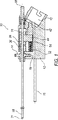
図1から7に、本発明にもとづく回転式外科装置10の一実施形態を示す。回転式外科装置10はハンドピース12を有する。ハンドピース12は回転式外科装置10を外科環境と係合させる基部として作用する。ある実施形態では、ハンドピース12は、駆動部材(図示せず)が駆動受け部13に対して角度をなしてハンドピース12内に係止される、人間工学的装置の一部である。ハンドピース12の非対称設計はハンドピース12の快適かつ正確な制御を可能にする。ハンドピース12は、外科医が外科装置10を快適に保持できるようにする人間工学装置として具現されるが、ハンドピース12はさらに、内視鏡(図示せず)のような他の医療機器とハンドピース12との整合を支援するために1つまたは複数のハンドピース案内部15を備えることができる。
1-7 illustrate one embodiment of a rotary surgical device 10 in accordance with the present invention. The rotary surgical device 10 has a
ハンドピース12には、外ハブ14、内ハブ16および外カニューレ18が連結される。外ハブ14(図3に最も良く示される)は、選択的回転動作を行うようにハンドピース12に取り付けられる。より詳細には、ハンドピース12は、外ハブ14のホイール20を受け入れる溝穴19を有する。溝穴19は、ホイール20が溝穴19の中を自由に回転できるように、幅および深さでホイール20を少なくともわずかに上回る寸法を有する。外ハブ14の遠位回転面22はホイール20の一方の側にあり、近位回転面24はホイール20のもう一方の側にある。回転面22、24は溝穴19の両側でハンドピース12と係合する(図1参照)。ある実施形態では、溝穴19内で外ハブ14をいずれかの方向に選択的に回転させるのに便利な親指用グリップを提供するように、ホイール20は、溝28によって隔てられたスポーク26を有することもできる(図2参照)。
An
外カニューレ18(図1参照)は、外ハブ14を貫通する外ハブチャネル30(図3参照)に挿通される。外カニューレ18はチャネル壁32に固定されるが、外カニューレ18の遠位端31は所定の距離だけハンドピース12から離れる方向に延びるように位置決めされる。外カニューレ18は外ハブ14に固定されるため、外ハブ14を回すと、外カニューレ18も回転し、外ハブ14との円周方向の位置合わせを保つ。
The outer cannula 18 (see FIG. 1) is inserted through an outer hub channel 30 (see FIG. 3) that penetrates the
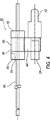
外ハブ14は、外ハブ14の後面から内側へ延びる1つまたは複数の案内穴34を備えることもできる。それぞれの案内穴34は案内ピン36の一端35を受け入れ、その一端35は案内穴34内に固定的に取り付けられる。案内ピン36は、摩擦接触、圧入、溶接または接着のような従来の方法を用いて案内穴34内に保持することができる。案内ピン36の他端37は、図1および7に最も良く示されるように、内ハブ16に形成された溝穴38内に受け入れられる。
The
図3では、案内ピン36はピン形コネクタとして具現されているが、案内ピン36は外ハブ14を内ハブ16に回転可能に連結するいかなる連結部材であってもよい。その場合、案内ピン36は、丸形、平形、矩形であっても、フランジまたはタブであってもよい。他の場合には、案内ピン36は外ハブ14または内ハブ16と一体をなす部分として成形することができる。別法として、案内ピン36は、外ハブ14と内ハブ16の両方の一部である要素として成形することができる。成形された2つの部分は係合して案内ピン36を形成するように構成される。案内ピン36は外ハブ14と内ハブ16の両方で取付け部によって緩い状態で受け入れられることもできる。さらに、案内ピン36は、外ハブ14と内ハブ16の両方に固定的に取り付けられた平板材として具現することができる。
In FIG. 3, the
図4は、内ハブ16がその一部をなす駆動装置40の側面図である。駆動装置40は、内ハブ16に加えて、カム従動子42と、駆動部材44と、図1の回転式外科装置10とともに使用する内カニューレ46とを備える。内カニューレ46は、内カニューレ46が内ハブ16を貫通して軸方向に延びるように、内ハブ16を貫通するチャネルを介して内ハブ16に固定される。駆動部材44は、内ハブ16を円周方向に囲むリング48によって内ハブ16に回転可能に取り付けられる。駆動部材44は回転するのではなく、内ハブ16に対して往復動作を与える。リング48は、内ハブ16が駆動部材44に対して自由に回転することを許容する溝50に嵌っている。
FIG. 4 is a side view of the driving
往復動作は、カム(図示せず)とカム従動子42によって回転式外科装置10に導入することができる。カム従動子42がカム(図示せず)と係合すると、駆動部材44は必ず駆動される。往復動作のための戻し力は、ばね案内54に沿って支承されるばね52(図1参照)を縮める力によって与えられる。内ハブ16と内カニューレ46はリング48によって駆動部材44に取り付けられているため、これらはカム従動子42によって往復駆動される。さらに、リング48が溝50に嵌るため、往復動作は内ハブ16に伝達される。
A reciprocating motion can be introduced into the rotary surgical device 10 by a cam (not shown) and a
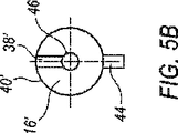
図5Aおよび5Bは、内ハブ16について、それぞれ代替の実施形態を示している。第1の実施形態では、内ハブ16は溝穴38を備える。溝穴38は、内ハブ16の外側面40から径方向内向きに延びるチャネルまたは切欠きである。溝穴38は、内カニューレ46の周りにランド部56を残して内カニューレ46から径方向に離れた位置から始まることができる(図4および5Aに図示)。第2の実施形態では、図5bに示すように、内ハブ16’には、内カニューレ46を受け入れるチャネルから内ハブ16の外側面40’に直接延びる溝穴38’を設けることができる。
5A and 5B show alternative embodiments for the
上述のように、案内ピン36は溝穴38で内ハブ16と係合する。従って、外ハブ14を回転させると、溝穴38は、内ハブ16がリング48によって駆動部材44に対して回転可能に取り付けられていることから、案内ピン36が内ハブ16を回転させることを可能にする。案内ピン36は、内ハブ16の軸線から所定の距離で回転力を内ハブ16に与える。内カニューレ46は内ハブ16に固定されているため、外ハブ14、外カニューレ18および案内ピン36を回転させると、内ハブ16と内カニューレ46も回転する。
As described above, the
溝穴38、38’のような案内ピン36の取付け部は、案内ピン38を受け入れるように構成された穴または特殊形状の空洞としても具現することができる。代替の実施形態では、取付け部は内カニューレ46内に形成することができる。取付け部は、往復動作を可能にするとともに、内カニューレ46を外カニューレ18と共に回転させるピンを受け入れるように内カニューレ46に設けられた溝穴として構成することができる。このような装置は、内カニューレ46内に導入される真空を保つように、取付け部の溝穴を覆うスカートをピンの周りに有することができる。
The mounting portion of the
図7に図示する例示的実施形態の場合のように、往復動作が望まれる場合は、案内ピン36が内ハブ16の溝穴38によって摺動可能に受け入れられることもできる。案内ピン36がスロット38によって受け入れられる場合は、内ハブ16は、内ハブ16の軸方向の往復動作を可能とするように構成される。内ハブ16が軸方向に往復動作するとき、案内ピン36は溝穴38の長さに沿って摺動する。案内ピン36が溝穴38によって摺動可能に受け入れられる一方、内ハブ16は外ハブ14および案内ピン36に関して内カニューレ46を回転させる能力を維持する。
If reciprocation is desired, as in the exemplary embodiment illustrated in FIG. 7, the
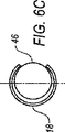
図3から7を参照すると、案内ピン36は外ハブ14に取り付けられており、外ハブ14を、外カニューレ18に収容された部品を含む切断装置100(図7に最も良く示される)に回転可能に連結する。切断装置100は、外カニューレ18の遠位端31に隣接して外カニューレ18に形成された組織受け口60と、選択的に往復動作する内カニューレ46とを有する選択的往復動カッター58(図6Aに最も良く示される)を有する。
3-7, the
操作時、内カニューレ46は外カニューレ18内で往復動作し、内カニューレ46の遠位端64を外カニューレ18の遠位端31に対して接近、離間それぞれの方向に動かす。真空Vは、内カニューレ46と作動的に係合する真空口66(図1に示す)によって与えられる。真空Vは、外カニューレ18に形成された組織受け口60を通して組織68を吸引するように作用する。内カニューレ46の遠位端64は、組織受け口60と協働して、組織受け口60を通して引き寄せられた組織68を切り取るように構成される。より具体的には、組織受け口60は、内カニューレ46の遠位端64と協働して組織を切り取るように構成された刃先72を有する。
In operation, the
内カニューレ46はヒンジ74も有することができる。ヒンジ74は、力が加えられたときに内カニューレ46の遠位端64が上向きに枢動できるようにする。ある実施形態では、ヒンジ74は内カニューレ46の一部を径方向に切り取った溝穴として構成される。
The
外カニューレ18を通じて引き寄せられた組織68に内カニューレ46が係合すると、内カニューレ46に対する押圧力と、遠位端64、組織68および刃先72の接触とによって、遠位端64に力Fが生じる。力Fは、内カニューレ46に切り込まれたヒンジ74のために内カニューレ64の遠位端64を時計方向Rに枢動させる。枢動Rは、遠位端64の頂部73と刃先72の狭間隔での位置合わせ(narrow gap alignment)を可能にし、これによって隙間がほとんどゼロの状態が実現する。この狭間隔は刃先72での組織68の一刀切断(first−cut severing)をもたらす。切り取られた組織76(図6A参照)が切り離されると、真空Vが切り取られた組織76を内カニューレ46に沿って引き寄せ、収集容器(図示せず)に捕集することができる。
When the
往復カッター58が適切に動作するように、ヒンジ74は、組織68が外カニューレ18内に引き込まれたとき、内カニューレ46の遠位端64が上向きに枢動し、組織68を刃先72に押し付けて切断するように、刃先72および組織受け口60と整合させられる。開示される一実施形態では、外ハブ14、案内ピン36および内ハブ16が協働することによってヒンジ74と刃先72の適正な位置合わせが保たれる。これらの要素は、内ハブ16と内カニューレ46が往復動作する間であっても、内カニューレ46と外カニューレ18の位置合わせを保つ。
In order for the
図6Bは、第1の枢動位置にある外カニューレ18と内カニューレ46を内カニューレ46の遠位端64付近で示したもので、内カニューレ46が刃先72近くまで上方に枢動している。図6Cは、第2の枢動位置にある外カニューレ18と内カニューレ46を示す。図示されているように、内カニューレ46の枢動部は外カニューレ18の刃先72に対する向きを保っている。そのため、往復カッター58が回転されるとき、切断装置100は内カニューレ46と外カニューレ18の円周方向の位置合わせを保つ。
FIG. 6B shows the
図1と7を参照しながら、回転式外科装置10の操作について説明する。まず、外科医はハンドピース12の快適な保持位置を決める。次に、外科医は除去されるべき病変部位に対して外カニューレ18が患者の体内に入る位置を決める。次いで、組織受け口60が除去されるべき病変部位の近くに位置するように外カニューレ18の遠位端31が手術部位に挿入される。その上で、外科医は、ホイール20を回すことによって、外カニューレ18に固定された外ハブ14を回転させることができる。外ハブ14をこうして回転させることにより、遠位端62に隣接して外カニューレ18に形成された組織受け口60を回転させて、病変部位に接近するのに適した角度にすることができる。外ハブ14に取り付けられた案内ピン36は、溝穴38、38’と係合することによって内ハブ16に取り付けられている。内カニューレ46は内ハブ16に固定されている。これによって、外ハブ14、案内ピン36および内ハブ16は協働して、軸方向の構成要素が互いに同じ相対位置(すなわち、円周方向の位置合わせまたは角度の位置合わせ)を保つことができるように外カニューレ18と内カニューレ46を回転させる。
The operation of the rotary surgical device 10 will be described with reference to FIGS. First, the surgeon determines a comfortable holding position for the
実際、人間工学的装置の一部であるハンドピース12に関して、これらの実施形態は、組織受け口60を選択的に位置決めするために外科医の手の中でハンドピース12を選択的に回転させることを可能にする。さらに、外カニューレ18の回転は、切断装置100の他の要素を同時に回転させることも可能にする。例えば、内カニューレ46が回転するとき、ヒンジ74および組織受け口60の位置合わせが保たれる(図6A参照)。溝穴38には、内ハブ16の往復動作を許容する案内空間78が設けられる。これによって、内ハブ16は往復動作を行いながら、案内ピン36との接触をなお維持することができる。図示されるように、この例示的実施形態は、組織受け口60がヒンジ74との適切な位置合わせを維持した状態で、内カニューレ46と外カニューレ18が共に回転することを容易にするものである。
In fact, with respect to
さらに、この例示的実施形態は、ハンドピース12の所望の人間工学的保持位置を保ちながら、切断装置100を回転させることを可能にするものでもある(図1参照)。実際、外科装置10は、外科医が組織受け口60を独立して回転させながらハンドピース12を保持することを可能にする。外科医が外ハブ14を回すと、外カニューレ18と内カニューレ46は、組織受け口60とヒンジ74が互いに一致して回転するように、同期して回転する。そのため、組織受け口60の向きを変えるために、外科医がハンドピース12を不便な、または快適でない位置で保持する必要がない。
Furthermore, this exemplary embodiment also allows the cutting device 100 to be rotated while maintaining the desired ergonomic holding position of the handpiece 12 (see FIG. 1). Indeed, the surgical device 10 allows the surgeon to hold the
さらに、外科医は、ハンドピース12を保持するのではなく、外科用安定化装置を用いることもでき、その場合には、医療処置の間、外科医がハンドピース12を保持する必要はない。安定化装置は、不動化された内視鏡として具現することができる。そのような装置の場合、ハンドピース12は1つまたは複数のハンドピース案内部15を用いて安定化装置に取り付けることができる。ハンドピース案内部15は、外科手術でハンドピース12を保持するように設計された安定化装置の受け入れ穴に差し入れることができる。ハンドピース12が安定化された後は、外科医は、手案内による操作と同様に安定化装置を外科手術用に位置決めすることができる。ハンドピース12を位置決めした後は、組織受け口60を外ハブ20によって選択的に回転させて病変部位に接近させることができる。
Further, rather than holding the
本発明について、上述の実施形態を参照しながら具体的に紹介し、説明してきたが、これらの実施形態は、本発明を実施するための最良の態様について説明するためのものにすぎない。本発明の実施に当たって、以下の請求項で定義する本発明の精神および範囲から外れることなく、ここに説明した本発明の実施形態に対する様々な代替法を用いることができることは、当業者には理解されるはずである。以下の請求項は本発明の範囲を規定するものであり、これらの請求項の範囲に含まれる方法および装置ならびにその等価物はそこに含まれるものとして意図されている。本発明に関するこの説明は、ここに記載する要素のあらゆる新規で自明でない組み合わせのすべてを含むものと理解される必要があり、これらの要素の新規で自明でない組み合わせに対して、これまたはこれ以降の出願で請求がなされる可能性がある。さらに、上述の実施形態は説明のためのものであって、いかなる特徴または要素も、これまたはこれ以降の出願において請求される可能性のある考えられる限りの組み合わせに不可欠なものではない。 Although the present invention has been specifically introduced and described with reference to the above-described embodiments, these embodiments are merely illustrative of the best mode for carrying out the invention. Those skilled in the art will appreciate that various alternatives to the embodiments of the invention described herein can be used in practicing the invention without departing from the spirit and scope of the invention as defined in the following claims. Should be done. The following claims are intended to define the scope of the invention, and the methods and apparatus included in the scope of these claims and their equivalents are intended to be included therein. This description of the invention should be understood to include all of the novel and non-obvious combinations of the elements described herein, with respect to the novel and non-obvious combinations of these elements. There may be a claim in the application. Furthermore, the above-described embodiments are illustrative, and no feature or element is essential to every possible combination that may be claimed in this or subsequent applications.
Claims (7)
前記内カニューレの少なくとも一部が前記外カニューレ内で往復動作し、
前記案内部が前記第1のハブに固定的に取り付けられ、且つ、前記第2のハブに摺動可能に係合する、回転式外科器具。 A first hub selectively rotated, an outer cannula engaged with the first hub to rotate when the first hub is rotated, a second hub, and the second hub An inner cannula engaged with a hub, and a guide portion rotatably connecting the first hub and the second hub, wherein the outer cannula and the outer cannula are selectively rotated when the outer cannula is selectively rotated. A rotary surgical instrument in which the inner cannulas maintain their orientation relative to each other,
At least a portion of the inner cannula reciprocates within the outer cannula;
A rotary surgical instrument, wherein the guide is fixedly attached to the first hub and slidably engages the second hub.
前記内カニューレの少なくとも一部が前記外カニューレ内で往復動作し、 At least a portion of the inner cannula reciprocates within the outer cannula;
前記案内部が前記第2のハブによって受け入れられ、これにより、前記第2のハブは、前記案内部との回転連結を維持すると共に往復動作することができる、回転式外科器具。 The rotary surgical instrument, wherein the guide is received by the second hub, whereby the second hub can maintain reciprocal connection with the guide and can reciprocate.
Applications Claiming Priority (3)
| Application Number | Priority Date | Filing Date | Title |
|---|---|---|---|
| US11/235,637 | 2005-09-26 | ||
| US11/235,637 US8187294B2 (en) | 2005-09-26 | 2005-09-26 | Rotating surgical cutter |
| PCT/IB2006/053378 WO2007034416A2 (en) | 2005-09-26 | 2006-09-19 | Rotating surgical cutter |
Publications (2)
| Publication Number | Publication Date |
|---|---|
| JP2009509611A JP2009509611A (en) | 2009-03-12 |
| JP4933552B2 true JP4933552B2 (en) | 2012-05-16 |
Family
ID=37863996
Family Applications (1)
| Application Number | Title | Priority Date | Filing Date |
|---|---|---|---|
| JP2008532926A Active JP4933552B2 (en) | 2005-09-26 | 2006-09-19 | Rotary surgical cutter |
Country Status (5)
| Country | Link |
|---|---|
| US (1) | US8187294B2 (en) |
| EP (1) | EP1933716A2 (en) |
| JP (1) | JP4933552B2 (en) |
| CA (1) | CA2622965A1 (en) |
| WO (1) | WO2007034416A2 (en) |
Families Citing this family (58)
| Publication number | Priority date | Publication date | Assignee | Title |
|---|---|---|---|---|
| JP4260024B2 (en) | 2002-03-19 | 2009-04-30 | バード ダブリン アイティーシー リミティッド | Vacuum biopsy device |
| AU2003218696A1 (en) | 2002-03-19 | 2003-09-29 | Bard Dublin Itc Limited | Biopsy device and biopsy needle module that can be inserted into the biopsy device |
| DE10314240B4 (en) | 2003-03-29 | 2025-05-28 | Bard Dublin Itc Ltd. | Pressure generation unit |
| EP1768571B1 (en) | 2004-07-09 | 2012-03-21 | Bard Peripheral Vascular, Inc. | Firing system for biopsy device |
| US7517321B2 (en) | 2005-01-31 | 2009-04-14 | C. R. Bard, Inc. | Quick cycle biopsy system |
| WO2007021904A2 (en) | 2005-08-10 | 2007-02-22 | C.R. Bard Inc. | Single-insertion, multiple sampling biopsy device usable with various transport systems and integrated markers |
| US8267868B2 (en) | 2005-08-10 | 2012-09-18 | C. R. Bard, Inc. | Single-insertion, multiple sample biopsy device with integrated markers |
| JP4955681B2 (en) | 2005-08-10 | 2012-06-20 | シー・アール・バード・インコーポレーテッド | Single insertion multiple sampling biopsy device with linear drive |
| US8251917B2 (en) | 2006-08-21 | 2012-08-28 | C. R. Bard, Inc. | Self-contained handheld biopsy needle |
| ATE493074T1 (en) | 2006-10-06 | 2011-01-15 | Bard Peripheral Vascular Inc | TISSUE HANDLING SYSTEM WITH REDUCED OPERATOR EXPOSURE |
| EP3714798A3 (en) | 2006-10-24 | 2020-12-16 | C. R. Bard, Inc. | Large sample low aspect ratio biopsy needle |
| US8241225B2 (en) | 2007-12-20 | 2012-08-14 | C. R. Bard, Inc. | Biopsy device |
| US7854706B2 (en) * | 2007-12-27 | 2010-12-21 | Devicor Medical Products, Inc. | Clutch and valving system for tetherless biopsy device |
| US8206315B2 (en) * | 2008-09-30 | 2012-06-26 | Suros Surgical Systems, Inc. | Real-time pathology |
| US10080578B2 (en) | 2008-12-16 | 2018-09-25 | Nico Corporation | Tissue removal device with adjustable delivery sleeve for neurosurgical and spinal surgery applications |
| US8430825B2 (en) * | 2008-12-16 | 2013-04-30 | Nico Corporation | Tissue removal device for neurosurgical and spinal surgery applications |
| US8496599B2 (en) * | 2008-12-16 | 2013-07-30 | Nico Corporation | Tissue removal device for neurosurgical and spinal surgery applications |
| US8702738B2 (en) * | 2008-12-16 | 2014-04-22 | Nico Corporation | Tissue removal device for neurosurgical and spinal surgery applications |
| US9931105B2 (en) | 2008-12-16 | 2018-04-03 | Nico Corporation | System and method of taking and collecting tissue cores for treatment |
| US8460327B2 (en) | 2008-12-16 | 2013-06-11 | Nico Corporation | Tissue removal device for neurosurgical and spinal surgery applications |
| US8657841B2 (en) | 2008-12-16 | 2014-02-25 | Nico Corporation | Tissue removal device for neurosurgical and spinal surgery applications |
| US9216031B2 (en) * | 2008-12-16 | 2015-12-22 | Nico Corporation | Tissue removal device with adjustable fluid supply sleeve for neurosurgical and spinal surgery applications |
| US9820480B2 (en) | 2008-12-16 | 2017-11-21 | Nico Corporation | System for collecting and preserving tissue cores |
| US20100152762A1 (en) * | 2008-12-16 | 2010-06-17 | Mark Joseph L | Tissue removal system with multi-directional foot actuator assembly for neurosurgical and spinal surgery applications |
| US9504247B2 (en) | 2008-12-16 | 2016-11-29 | Nico Corporation | System for collecting and preserving tissue cores |
| US8357175B2 (en) * | 2008-12-16 | 2013-01-22 | Nico Corporation | Positioning system for tissue removal device |
| US9655639B2 (en) * | 2008-12-16 | 2017-05-23 | Nico Corporation | Tissue removal device for use with imaging devices in neurosurgical and spinal surgery applications |
| US10368890B2 (en) | 2008-12-16 | 2019-08-06 | Nico Corporation | Multi-functional surgical device for neurosurgical and spinal surgery applications |
| US9279751B2 (en) | 2008-12-16 | 2016-03-08 | Nico Corporation | System and method of taking and collecting tissue cores for treatment |
| WO2010107424A1 (en) | 2009-03-16 | 2010-09-23 | C.R. Bard, Inc. | Biopsy device having rotational cutting |
| ES2690737T3 (en) | 2009-04-15 | 2018-11-22 | C.R. Bard Inc. | Fluid management |
| US8206316B2 (en) | 2009-06-12 | 2012-06-26 | Devicor Medical Products, Inc. | Tetherless biopsy device with reusable portion |
| EP2464294B1 (en) | 2009-08-12 | 2019-10-02 | C.R. Bard Inc. | Biopsy appaparatus having integrated thumbwheel mechanism for manual rotation of biopsy cannula |
| US8283890B2 (en) | 2009-09-25 | 2012-10-09 | Bard Peripheral Vascular, Inc. | Charging station for battery powered biopsy apparatus |
| US8430824B2 (en) | 2009-10-29 | 2013-04-30 | Bard Peripheral Vascular, Inc. | Biopsy driver assembly having a control circuit for conserving battery power |
| US8485989B2 (en) | 2009-09-01 | 2013-07-16 | Bard Peripheral Vascular, Inc. | Biopsy apparatus having a tissue sample retrieval mechanism |
| US8597206B2 (en) | 2009-10-12 | 2013-12-03 | Bard Peripheral Vascular, Inc. | Biopsy probe assembly having a mechanism to prevent misalignment of components prior to installation |
| US9060760B2 (en) * | 2011-08-18 | 2015-06-23 | Hologic, Inc. | Tissue removal system |
| US8790361B2 (en) * | 2012-05-23 | 2014-07-29 | Depuy Mitek, Llc | Methods and devices for cutting and removing tissue from a body |
| US10102390B2 (en) | 2012-06-28 | 2018-10-16 | Honeywell International Inc. | Memory authentication with redundant encryption |
| US9968338B2 (en) | 2012-11-21 | 2018-05-15 | C. R. Bard, Inc. | Core needle biopsy device |
| US9259211B2 (en) | 2012-12-24 | 2016-02-16 | Transmed7, Llc | Automated, selectable, soft tissue excision biopsy devices and methods |
| USD735332S1 (en) | 2013-03-06 | 2015-07-28 | C. R. Bard, Inc. | Biopsy device |
| USD737440S1 (en) | 2013-03-07 | 2015-08-25 | C. R. Bard, Inc. | Biopsy device |
| ES2875575T3 (en) | 2013-03-20 | 2021-11-10 | Bard Peripheral Vascular Inc | Biopsy device |
| USD735333S1 (en) | 2013-06-26 | 2015-07-28 | C. R. Bard, Inc. | Biopsy device |
| EP3549533B1 (en) | 2013-11-05 | 2020-12-30 | C.R. Bard, Inc. | Biopsy device having integrated vacuum |
| US20150190163A1 (en) * | 2014-01-06 | 2015-07-09 | Boston Scientific Scimed, Inc. | Medical devices for tissue extraction and related methods |
| US10013363B2 (en) | 2015-02-09 | 2018-07-03 | Honeywell International Inc. | Encryption using entropy-based key derivation |
| JP6636136B2 (en) | 2015-05-01 | 2020-01-29 | シー・アール・バード・インコーポレーテッドC R Bard Incorporated | Biopsy device |
| US10708073B2 (en) | 2016-11-08 | 2020-07-07 | Honeywell International Inc. | Configuration based cryptographic key generation |
| US10874416B2 (en) * | 2017-02-02 | 2020-12-29 | Biosense Webster (Israel) Ltd. | Surgical cutting instrument with extended blades |
| US11844500B2 (en) | 2017-05-19 | 2023-12-19 | Merit Medical Systems, Inc. | Semi-automatic biopsy needle device and methods of use |
| EP3624697B1 (en) | 2017-05-19 | 2024-02-14 | Merit Medical Systems, Inc. | Biopsy needle devices and methods of use |
| WO2018213580A1 (en) | 2017-05-19 | 2018-11-22 | Merit Medical Systems, Inc. | Rotating biopsy needle |
| US11129600B2 (en) * | 2018-05-28 | 2021-09-28 | Transmed7 Llc | Devices and methods for soft tissue biopsy and tissue sample collection |
| US12295556B2 (en) | 2019-09-27 | 2025-05-13 | Merit Medical Systems, Inc. | Rotation biopsy system and handle |
| US12150627B2 (en) | 2019-12-11 | 2024-11-26 | Merit Medical Systems, Inc. | Bone biopsy device and related methods |
Family Cites Families (17)
| Publication number | Priority date | Publication date | Assignee | Title |
|---|---|---|---|---|
| US2487502A (en) * | 1945-09-26 | 1949-11-08 | American Cystoscope Makers Inc | Instrument for electrosurgical resection |
| US2850007A (en) * | 1956-05-31 | 1958-09-02 | American Cyanamid Co | Biopsy device |
| US3995619A (en) * | 1975-10-14 | 1976-12-07 | Glatzer Stephen G | Combination subcutaneous suture remover, biopsy sampler and syringe |
| US6346107B1 (en) * | 1990-12-14 | 2002-02-12 | Robert L. Cucin | Power-assisted liposuction instrument with cauterizing cannual assembly |
| CA2161688A1 (en) * | 1993-05-07 | 1994-11-24 | Sdgi Holdings, Inc. | Surgical cutting instrument |
| US5649547A (en) | 1994-03-24 | 1997-07-22 | Biopsys Medical, Inc. | Methods and devices for automated biopsy and collection of soft tissue |
| US5526822A (en) | 1994-03-24 | 1996-06-18 | Biopsys Medical, Inc. | Method and apparatus for automated biopsy and collection of soft tissue |
| US5769086A (en) * | 1995-12-06 | 1998-06-23 | Biopsys Medical, Inc. | Control system and method for automated biopsy device |
| US6749576B2 (en) | 1996-01-26 | 2004-06-15 | Allegiance Corporation | Biopsy device with adjustable sampling |
| US6468228B1 (en) * | 1996-06-18 | 2002-10-22 | Vance Products Incorporated | Surgical tissue morcellator |
| US6454727B1 (en) | 1998-03-03 | 2002-09-24 | Senorx, Inc. | Tissue acquisition system and method of use |
| US8282573B2 (en) | 2003-02-24 | 2012-10-09 | Senorx, Inc. | Biopsy device with selectable tissue receiving aperture orientation and site illumination |
| US6402701B1 (en) * | 1999-03-23 | 2002-06-11 | Fna Concepts, Llc | Biopsy needle instrument |
| JP2001104313A (en) * | 1999-10-06 | 2001-04-17 | Asahi Optical Co Ltd | Endoscope tissue collection tool |
| US6485436B1 (en) | 2000-08-10 | 2002-11-26 | Csaba Truckai | Pressure-assisted biopsy needle apparatus and technique |
| US7458940B2 (en) * | 2000-11-06 | 2008-12-02 | Suros Surgical Systems, Inc. | Biopsy apparatus |
| US9408592B2 (en) | 2003-12-23 | 2016-08-09 | Senorx, Inc. | Biopsy device with aperture orientation and improved tip |
-
2005
- 2005-09-26 US US11/235,637 patent/US8187294B2/en active Active
-
2006
- 2006-09-19 JP JP2008532926A patent/JP4933552B2/en active Active
- 2006-09-19 WO PCT/IB2006/053378 patent/WO2007034416A2/en not_active Ceased
- 2006-09-19 CA CA002622965A patent/CA2622965A1/en not_active Abandoned
- 2006-09-19 EP EP06809347A patent/EP1933716A2/en not_active Withdrawn
Also Published As
| Publication number | Publication date |
|---|---|
| EP1933716A2 (en) | 2008-06-25 |
| WO2007034416A2 (en) | 2007-03-29 |
| WO2007034416A3 (en) | 2007-07-19 |
| JP2009509611A (en) | 2009-03-12 |
| CA2622965A1 (en) | 2007-03-29 |
| US20070073326A1 (en) | 2007-03-29 |
| US8187294B2 (en) | 2012-05-29 |
Similar Documents
| Publication | Publication Date | Title |
|---|---|---|
| JP4933552B2 (en) | Rotary surgical cutter | |
| US6958071B2 (en) | Surgical tool system | |
| CA2567638C (en) | Surgical cutting instrument | |
| JP4299278B2 (en) | Surgical attachment system | |
| US8435259B2 (en) | Surgical tool arrangement and surgical cutting accessory for use therewith with the tool arrangement including a toothed cutting edge and a generally straight cutting edge | |
| EP2667803B1 (en) | Surgical cutting instrument with distal suction capability | |
| US20260083471A1 (en) | Surgical Instrument Including A Cutting Assembly Providing Suction And Irrigation | |
| US8657840B2 (en) | Surgical instrument with distal suction capability | |
| US20040243163A1 (en) | Surgical instrument | |
| EP3672504A1 (en) | Control system for retrograde drill medical device | |
| JP2000508206A (en) | Surgical equipment | |
| KR200487712Y1 (en) | Shaver For Surgery | |
| EP3831320B1 (en) | Tissue resecting instrument | |
| EP3831319B1 (en) | Tissue resecting instrument | |
| EP3357440B1 (en) | Surgical cutting instrument with extended blades | |
| US11992261B2 (en) | Locking mechanism and sliding conductor for extendable shaft | |
| US12611220B2 (en) | Reciprocating serrated blade for precision dissection |
Legal Events
| Date | Code | Title | Description |
|---|---|---|---|
| A621 | Written request for application examination |
Free format text: JAPANESE INTERMEDIATE CODE: A621 Effective date: 20090804 |
|
| A131 | Notification of reasons for refusal |
Free format text: JAPANESE INTERMEDIATE CODE: A131 Effective date: 20110811 |
|
| RD04 | Notification of resignation of power of attorney |
Free format text: JAPANESE INTERMEDIATE CODE: A7424 Effective date: 20110913 |
|
| A601 | Written request for extension of time |
Free format text: JAPANESE INTERMEDIATE CODE: A601 Effective date: 20111110 |
|
| A602 | Written permission of extension of time |
Free format text: JAPANESE INTERMEDIATE CODE: A602 Effective date: 20111117 |
|
| A521 | Request for written amendment filed |
Free format text: JAPANESE INTERMEDIATE CODE: A523 Effective date: 20111209 |
|
| TRDD | Decision of grant or rejection written | ||
| A01 | Written decision to grant a patent or to grant a registration (utility model) |
Free format text: JAPANESE INTERMEDIATE CODE: A01 Effective date: 20120202 |
|
| A01 | Written decision to grant a patent or to grant a registration (utility model) |
Free format text: JAPANESE INTERMEDIATE CODE: A01 |
|
| A61 | First payment of annual fees (during grant procedure) |
Free format text: JAPANESE INTERMEDIATE CODE: A61 Effective date: 20120216 |
|
| R150 | Certificate of patent or registration of utility model |
Ref document number: 4933552 Country of ref document: JP Free format text: JAPANESE INTERMEDIATE CODE: R150 Free format text: JAPANESE INTERMEDIATE CODE: R150 |
|
| FPAY | Renewal fee payment (event date is renewal date of database) |
Free format text: PAYMENT UNTIL: 20150224 Year of fee payment: 3 |
|
| R250 | Receipt of annual fees |
Free format text: JAPANESE INTERMEDIATE CODE: R250 |
|
| R250 | Receipt of annual fees |
Free format text: JAPANESE INTERMEDIATE CODE: R250 |
|
| R250 | Receipt of annual fees |
Free format text: JAPANESE INTERMEDIATE CODE: R250 |
|
| R250 | Receipt of annual fees |
Free format text: JAPANESE INTERMEDIATE CODE: R250 |
|
| R250 | Receipt of annual fees |
Free format text: JAPANESE INTERMEDIATE CODE: R250 |
|
| R250 | Receipt of annual fees |
Free format text: JAPANESE INTERMEDIATE CODE: R250 |
|
| R250 | Receipt of annual fees |
Free format text: JAPANESE INTERMEDIATE CODE: R250 |
|
| R250 | Receipt of annual fees |
Free format text: JAPANESE INTERMEDIATE CODE: R250 |
|
| R250 | Receipt of annual fees |
Free format text: JAPANESE INTERMEDIATE CODE: R250 |
|
| R250 | Receipt of annual fees |
Free format text: JAPANESE INTERMEDIATE CODE: R250 |
|
| R250 | Receipt of annual fees |
Free format text: JAPANESE INTERMEDIATE CODE: R250 |
|
| R250 | Receipt of annual fees |
Free format text: JAPANESE INTERMEDIATE CODE: R250 |