JP4931376B2 - Substrate heating device - Google Patents

Substrate heating device Download PDF

Info

Publication number
JP4931376B2
JP4931376B2 JP2005183921A JP2005183921A JP4931376B2 JP 4931376 B2 JP4931376 B2 JP 4931376B2 JP 2005183921 A JP2005183921 A JP 2005183921A JP 2005183921 A JP2005183921 A JP 2005183921A JP 4931376 B2 JP4931376 B2 JP 4931376B2
Authority
JP
Japan
Prior art keywords
substrate
base material
ceramic
temperature
heating element
Prior art date
Legal status (The legal status is an assumption and is not a legal conclusion. Google has not performed a legal analysis and makes no representation as to the accuracy of the status listed.)
Active
Application number
JP2005183921A
Other languages
Japanese (ja)
Other versions
JP2006049844A (en
Inventor
義信 後藤
英芳 鶴田
Current Assignee (The listed assignees may be inaccurate. Google has not performed a legal analysis and makes no representation or warranty as to the accuracy of the list.)
NGK Insulators Ltd
Original Assignee
NGK Insulators Ltd
Priority date (The priority date is an assumption and is not a legal conclusion. Google has not performed a legal analysis and makes no representation as to the accuracy of the date listed.)
Filing date
Publication date
Application filed by NGK Insulators Ltd filed Critical NGK Insulators Ltd
Priority to JP2005183921A priority Critical patent/JP4931376B2/en
Publication of JP2006049844A publication Critical patent/JP2006049844A/en
Application granted granted Critical
Publication of JP4931376B2 publication Critical patent/JP4931376B2/en
Active legal-status Critical Current
Anticipated expiration legal-status Critical

Links

Images

Description

本発明は、基板を加熱する基板加熱装置に関する。   The present invention relates to a substrate heating apparatus for heating a substrate.

半導体製造プロセスなどでは、基板加熱装置として、円盤状のセラミックス基材中に線状の抵抗発熱体を埋設したセラミックスヒータが広く使用されている。   In a semiconductor manufacturing process or the like, a ceramic heater in which a linear resistance heating element is embedded in a disk-shaped ceramic base material is widely used as a substrate heating device.

また、最近の半導体製造プロセスでは、基板加熱方法として、セラミックスヒータを使用した接触式の加熱のみならず、ハロゲンランプなどを使用した非接触式のランプ加熱も積極的に利用されている。ランプ加熱装置を使用する場合においても、セラミックスヒータは基板を補助的に加熱するために併用されることが多い。   In recent semiconductor manufacturing processes, not only contact heating using a ceramic heater but also non-contact lamp heating using a halogen lamp or the like is actively used as a substrate heating method. Even in the case of using a lamp heating device, the ceramic heater is often used in combination to supplementarily heat the substrate.

半導体製造プロセスでは、製品の歩留まりを上げるため、基板表面温度を高い精度で均熱化することが求められている。したがって、セラミックスヒータに対しては、基板周囲の環境に合わせたより細やかな温度調整が求められている。例えば、基板加熱面内の場所により最適な発熱量を調整できるよう、セラミックス基材内を複数のゾーンに分け、ゾーンごとに最適な発熱量を設定するマルチゾーンヒータが検討されている(例えば、特許文献1参照)。特許文献1には、セラミックス基体内に9ゾーンの抵抗発熱体を埋設したものが提案されている。従来のマルチゾーンヒータは、いずれも一体型の基材内に複数の抵抗発熱体を埋設したものである。
特開2001−52843号
In the semiconductor manufacturing process, it is required to equalize the substrate surface temperature with high accuracy in order to increase the yield of products. Therefore, finer temperature adjustments are required for ceramic heaters according to the environment around the substrate. For example, a multi-zone heater in which the inside of a ceramic substrate is divided into a plurality of zones so that the optimum heat generation amount can be adjusted depending on the location within the substrate heating surface, and an optimum heat generation amount is set for each zone has been studied (for example, Patent Document 1). Patent Document 1 proposes a 9-zone resistance heating element embedded in a ceramic substrate. All conventional multi-zone heaters have a plurality of resistance heating elements embedded in an integral base material.
JP 2001-52843 A

しかしながら、従来の一体型の基材において、場所により発熱量を変更させるマルチゾーンヒータでは、一体型の基材において、局所的に高温部や低温部が形成される。よって、抵抗発熱体が埋設された基材に局所的な応力が発生しやすい。特に、セラミックス基材は、圧縮応力に比べ引張り応力に弱い傾向がある。そのため、引張り応力が発生する高温部や低温部の周辺部において、破損が生じやすくなる。   However, in a conventional multi-zone heater in which the amount of heat generated is changed depending on the location in an integrated base material, a high temperature portion and a low temperature portion are locally formed in the integrated base material. Therefore, local stress is likely to occur in the base material in which the resistance heating element is embedded. In particular, ceramic substrates tend to be weaker in tensile stress than compressive stress. Therefore, breakage is likely to occur in the high temperature part where the tensile stress is generated and in the peripheral part of the low temperature part.

また、セラミックスヒータに限らず、基板を載置する基材として金属や樹脂を使用した基板加熱装置においても、場所による設定温度の相違に基づく応力発生の問題は存在する。   Further, not only the ceramic heater but also a substrate heating apparatus using a metal or a resin as a base material on which a substrate is placed, there is a problem of stress generation based on a difference in set temperature depending on a place.

本発明は、場所により異なる温度設定を行うことによる破損を防止した基板加熱装置を提供することを目的とする。   An object of this invention is to provide the board | substrate heating apparatus which prevented the damage by performing different temperature setting by a place.

本発明に係る基板加熱装置は、ギャップを介して略板状になるように配置され、基板載置面を形成する複数の基材を含む基材群と、少なくとも1つの基材に設けられた抵抗発熱体とを備えることを特徴とする。   The substrate heating apparatus according to the present invention is disposed so as to be substantially plate-shaped via a gap, and is provided on a substrate group including a plurality of substrates that form a substrate mounting surface, and at least one substrate. And a resistance heating element.

このような基板加熱装置によれば、従来一体型であった基材を複数に分割し、分割された複数の基材をギャップを介して配置させている。そのため、分割された基材ごとに異なる温度設定を行っても、ギャップの存在により一つの基材内に発生する温度勾配が抑制される。これにより、分割された基材ごとの設定温度の相違に基づき発生する応力が低減される。更に、ギャップにより応力の逃げ場を提供できるため、基材の破損を防止できる。   According to such a substrate heating apparatus, the base material which has been conventionally integrated is divided into a plurality of parts, and the plurality of divided base parts are arranged via the gap. Therefore, even if different temperature settings are performed for each divided base material, the temperature gradient generated in one base material due to the presence of the gap is suppressed. Thereby, the stress which generate | occur | produces based on the difference of the preset temperature for every divided base material is reduced. Furthermore, since the stress can be provided by the gap, the base material can be prevented from being damaged.

以上説明したように、本発明によれば、場所により異なる温度設定を行うことによる破損を防止した基板加熱装置を提供することができる。   As described above, according to the present invention, it is possible to provide a substrate heating apparatus that prevents damage due to different temperature settings depending on locations.

本発明の実施の形態に係る基板加熱装置は、基材を複数の領域毎に分割し、分割された複数の基材を基材間にギャップを設けて、複数の基材全体が1つの略板状体になるよう配置させた基板加熱装置である。複数の基材群は、基板載置面を形成する。また、少なくとも1つの基材に抵抗発熱体が設けられる。   In the substrate heating apparatus according to the embodiment of the present invention, the base material is divided into a plurality of regions, a plurality of divided base materials are provided with gaps between the base materials, and the whole of the plurality of base materials is substantially one. A substrate heating device arranged to be a plate-like body. The plurality of base material groups form a substrate placement surface. In addition, a resistance heating element is provided on at least one substrate.

従来一体型であった基材を複数に分割し、ギャップを介して配置させることにより、個々の基材を独立させることができる。そのため、場所による設定温度の相違に基づく応力の発生を抑制できる。基材の分割の形態や数は限定されず、基板加熱装置が配置される周囲の環境や所望の基板温度分布に応じて選択することができる。また、基材は、金属、樹脂、セラミックスいずれも使用できる。以下、図面を参照して各実施の形態に係る基板加熱装置についてより具体的に説明する。   Individual substrates can be made independent by dividing the substrate, which has conventionally been an integral type, into a plurality of parts and arranging them through gaps. Therefore, it is possible to suppress the generation of stress based on the difference in set temperature depending on the location. The form and number of base materials are not limited and can be selected according to the surrounding environment in which the substrate heating apparatus is disposed and the desired substrate temperature distribution. Moreover, any of metal, resin, and ceramics can be used for the substrate. Hereinafter, the substrate heating apparatus according to each embodiment will be described more specifically with reference to the drawings.

(第1の実施の形態)
第1の実施の形態に係る基板加熱装置は、基材としてセラミックスを使用したセラミックスヒータである。図1(a)に、セラミックスヒータ10の断面図を示す。また、図1(b)に、セラミックス基材群20の平面図を示す。
(First embodiment)
The substrate heating apparatus according to the first embodiment is a ceramic heater using ceramics as a base material. FIG. 1A shows a cross-sectional view of the ceramic heater 10. Moreover, the top view of the ceramic base material group 20 is shown in FIG.1 (b).

セラミックスヒータ10は、従来一体であった円盤状のセラミックス基材を中央部のセラミックス基材20Aとその外周部のセラミックス基材20Bとに二分割し、ギャップGを介して両者を同一面上に配置させたセラミックス基材群20を有する。即ち、セラミックス基材群20は、第1基材となるセラミックス基材20Aと、第1基材の外周囲に配置される環状の第2基材となるセラミックス基材20Bとを含む。セラミックスヒータ10では、円盤状のセラミックス基材20Aと、それを囲む円環状のセラミックス基材20Bを用いる。   The ceramic heater 10 divides a disk-shaped ceramic base material, which has been conventionally integrated, into a ceramic base material 20A at the center and a ceramic base material 20B at the outer periphery thereof, and both are placed on the same plane via a gap G. It has the ceramic base material group 20 arrange | positioned. That is, the ceramic base material group 20 includes a ceramic base material 20A serving as a first base material and a ceramic base material 20B serving as an annular second base material disposed around the outer periphery of the first base material. In the ceramic heater 10, a disk-shaped ceramic base material 20A and an annular ceramic base material 20B surrounding it are used.

セラミックス基材20Aとセラミックス基材20Bは、ギャップを介して略板状になるように配置され、基板載置面10aを形成する。図1では、セラミックス基材20Aとセラミックス基材20Bは、円盤状のセラミックス基材群20を形成する。よって、被加熱体である基板5は、セラミックス基材群20の一方の面である基板載置面10a上に載置される。基板5には、例えば、半導体ウエハや液晶基板などがある。   The ceramic base material 20A and the ceramic base material 20B are disposed so as to be substantially plate-shaped via a gap, and form the substrate mounting surface 10a. In FIG. 1, the ceramic substrate 20 </ b> A and the ceramic substrate 20 </ b> B form a disk-shaped ceramic substrate group 20. Therefore, the substrate 5 that is the object to be heated is placed on the substrate placement surface 10 a that is one surface of the ceramic base group 20. Examples of the substrate 5 include a semiconductor wafer and a liquid crystal substrate.

抵抗発熱体30は、少なくとも1つの基材に設けられればよい。図1(a)では、中央部のセラミックス基材20Aには抵抗発熱体は設けず、外周部のセラミックス基材20Bに抵抗発熱体30が埋設されている。抵抗発熱体30の形状は特に限定されるものではないが、例えば、図1(b)に示すように、線状の金属バルク体を螺旋状に配置させたることができる。   The resistance heating element 30 may be provided on at least one base material. In FIG. 1A, the resistance heating element 30 is embedded in the ceramic base material 20B in the outer peripheral part without providing the resistance heating element in the ceramic base material 20A in the central part. The shape of the resistance heating element 30 is not particularly limited. For example, as shown in FIG. 1B, linear metal bulk bodies can be arranged in a spiral shape.

更に、セラミックスヒータ10は、セラミックス基材群20の基板載置面10aと反対の面の中央部に、直接的または間接的に接続された管状部材40を備えることができる。例えば、図1(a)に示すように、円筒形の管状部材40は、セラミックス基材群20の基板載置面10aと反対の面(裏面)に直接接続されることができる。セラミックス基材群20は、管状部材40によって裏面から支持される。   Furthermore, the ceramic heater 10 can include a tubular member 40 that is directly or indirectly connected to the central portion of the surface of the ceramic base material group 20 opposite to the substrate mounting surface 10a. For example, as shown in FIG. 1A, the cylindrical tubular member 40 can be directly connected to a surface (back surface) opposite to the substrate mounting surface 10 a of the ceramic base material group 20. The ceramic substrate group 20 is supported from the back surface by the tubular member 40.

管状部材40は、セラミックス基材群20を支持する。管状部材40の端部は、装置の壁に固定できる。管状部材40は、抵抗発熱体30の端子30T1、30T2に接続する給電線50の保護管としても機能できる。管状部材40は、セラミックス基材20A,20Bそれぞれにねじ止めにより接続してもよく、ロウ付けにより接続してもよい。   The tubular member 40 supports the ceramic substrate group 20. The end of the tubular member 40 can be secured to the wall of the device. The tubular member 40 can also function as a protective tube for the feeder 50 connected to the terminals 30T1 and 30T2 of the resistance heating element 30. The tubular member 40 may be connected to the ceramic bases 20A and 20B by screwing or may be connected by brazing.

尚、セラミックス基材群20は、使用用途や使用条件などによっては、管状部材40にかえて、簡易な支持台上や装置上に、直接または間接的に載置してもよい。この場合、支持台や装置が、セラミックス基材群20を支持する。   The ceramic base material group 20 may be placed directly or indirectly on a simple support base or device instead of the tubular member 40 depending on the use application or use conditions. In this case, the support base and the device support the ceramic substrate group 20.

更に、抵抗発熱体30の端子30T1,30T2には、給電線50が接続される。端子30T1,30T2には、給電線50から電力の入力を受け、抵抗発熱体30に電力を出力する。給電線50は、各セラミックス基材20A,20B中に埋設させずに、図1(a)に示すように、セラミックス基材20A,20Bの基板載置面10aと反対の面(セラミックス基材の外表面)に沿って配線することができる。これによれば、給電線50としてより低抵抗な材料を使用することができ、給電線50自体からの発熱を防止できる。   Further, the feeder line 50 is connected to the terminals 30T1 and 30T2 of the resistance heating element 30. The terminals 30 </ b> T <b> 1 and 30 </ b> T <b> 2 receive power input from the power supply line 50 and output power to the resistance heating element 30. As shown in FIG. 1A, the feeder line 50 is not embedded in each ceramic base material 20A, 20B, but the surface opposite to the substrate mounting surface 10a of the ceramic base material 20A, 20B (ceramic base material). Wiring can be performed along the outer surface. According to this, a lower resistance material can be used as the feeder 50, and heat generation from the feeder 50 itself can be prevented.

尚、給電線50は、各セラミックス基材20A,20Bにそれぞれ埋設し、各セラミックス基材20A,20B内に配線してもよい。これによれば、給電線50がセラミックス基材外部に露出しないので、給電線50の腐食を防止できる。この場合、給電線50として、セラミックス基材20A,20Bの焼成温度に耐えられる材料を使用することが好ましい。例えば、給電線50として、抵抗発熱体30と同様の耐熱性導電材料を使用できる。このような材料の抵抗は比較的大きいため、給電線から発熱する場合がある。   The power supply line 50 may be embedded in each ceramic base material 20A, 20B and wired in each ceramic base material 20A, 20B. According to this, since the feed line 50 is not exposed to the outside of the ceramic substrate, corrosion of the feed line 50 can be prevented. In this case, it is preferable to use a material that can withstand the firing temperature of the ceramic substrates 20A and 20B as the power supply line 50. For example, a heat-resistant conductive material similar to that of the resistance heating element 30 can be used as the feeder line 50. Since the resistance of such a material is relatively large, heat may be generated from the power supply line.

セラミックスヒータ10では、外周部のセラミックス基材20Bのみに抵抗発熱体30を埋設している。そのため、セラミックスヒータ10の中央部、すなわちセラミックス基材20Aを低温に維持したまま、外周部のセラミックス基材20Bのみを高温に設定することができる。   In the ceramic heater 10, the resistance heating element 30 is embedded only in the ceramic substrate 20B on the outer peripheral portion. Therefore, only the ceramic substrate 20B at the outer peripheral portion can be set to a high temperature while the central portion of the ceramic heater 10, that is, the ceramic substrate 20A is maintained at a low temperature.

従来のように一体型のセラミックス基材を使用し、外周部のみを抵抗加熱体により加熱する場合は、中央部と外周部の設定温度差が一定値を超えると、中央部と外周部の境界部分で、熱勾配による強い引張り応力が発生する。その結果、破損するおそれがある。しかし、セラミックスヒータ10では、中央部のセラミックス基材20Aと外周部のセラミックス基材20Bとの間にギャップGが設けられているため、各セラミックス基材20A,20Bが熱膨張して生じる応力を逃がす場を提供することができる。更に、ギャップGの持つ断熱効果のため、各セラミックス基材は、お互いに、隣接する他のセラミックス基材の設定温度の影響を受けにくい。よって、単一の基材中で大きな温度勾配が生じるのを防止するとともに、分割された各基材が独立に、より正確に温度設定することができる。したがって、場所による設定温度の相違に基づくセラミックス基材の破損を防止できる。   When using an integrated ceramic substrate as in the past and heating only the outer periphery with a resistance heating element, if the temperature difference between the center and the outer periphery exceeds a certain value, the boundary between the center and the outer periphery In part, strong tensile stress due to thermal gradient is generated. As a result, there is a risk of damage. However, in the ceramic heater 10, since the gap G is provided between the ceramic base material 20A in the central portion and the ceramic base material 20B in the outer peripheral portion, the stress generated by thermal expansion of each ceramic base material 20A, 20B is generated. A place to escape can be provided. Furthermore, because of the heat insulating effect of the gap G, the ceramic substrates are not easily affected by the set temperatures of the other adjacent ceramic substrates. Therefore, it is possible to prevent a large temperature gradient from occurring in a single base material and to set the temperature of each divided base material more accurately independently. Therefore, it is possible to prevent the ceramic substrate from being damaged based on the difference in the set temperature depending on the place.

ギャップGの大きさ(ギャップGの幅)は、セラミックスヒータ10の大きさや各セラミックス基材20A,20Bの設定温度にも依存するが、0.1mm〜10mmであることが好ましい。ギャップGを0.1mm以上とすることにより、加熱時の熱膨張により隣接するセラミックス基材20A,20B同士が接触することを防止でき、破損をより一層防止できる。ギャップGを10mm以下とすることにより、ギャップGがコールドゾーンとなることを防止でき、基板5の均熱化を図ることができる。ギャップGは、より好ましくは0.2mm〜5mm、さらに好ましくは0.4mm〜3mmとできる。   The size of the gap G (width of the gap G) depends on the size of the ceramic heater 10 and the set temperature of each ceramic substrate 20A, 20B, but is preferably 0.1 mm to 10 mm. By setting the gap G to be 0.1 mm or more, it is possible to prevent the adjacent ceramic base materials 20A and 20B from coming into contact with each other due to thermal expansion during heating, and damage can be further prevented. By setting the gap G to 10 mm or less, the gap G can be prevented from becoming a cold zone, and the substrate 5 can be heated uniformly. The gap G is more preferably 0.2 mm to 5 mm, and still more preferably 0.4 mm to 3 mm.

セラミックスヒータ10のように、中央部のセラミックス基材20Aを低温に保持し、外周部のセラミックス基材20Bのみを高温に設定する使用方法は、例えばハロゲンランプ等を用いたランプ加熱装置を併用し、基板5を加熱する場合に好適に使用される。すなわち、基板5の中央部に関しては、基板5の上方に配置したランプ加熱装置からの放射で基板を加熱できる。一方、基板5の外周部は、放熱が大きく冷え易いため、ランプ加熱装置のみでは基板5の中央部ほど温度が上がらない。よって、セラミックスヒータ10で、基板5の外周部のみを加熱することで、基板5全体の温度の均熱化を図ることができる。   As in the ceramic heater 10, a method of using a lamp heating device using, for example, a halogen lamp is used in combination with a ceramic substrate 20A in the central portion kept at a low temperature and only the ceramic substrate 20B in the outer peripheral portion set at a high temperature. It is preferably used when the substrate 5 is heated. That is, with respect to the central portion of the substrate 5, the substrate can be heated by radiation from a lamp heating device disposed above the substrate 5. On the other hand, the outer peripheral portion of the substrate 5 has a large amount of heat dissipation and is easily cooled. Therefore, by heating only the outer peripheral portion of the substrate 5 with the ceramic heater 10, the temperature of the entire substrate 5 can be equalized.

次に、セラミックスヒータ10の各構成材料について、より具体的に説明する。セラミックス基材群20の材質は特に限定されないが、窒化アルミニウム(AlN)、アルミナ(Al23)、窒化珪素(SiN)、炭化珪素(SiC)、ムライト(Al6Si213)、窒化ホウ素(BN)、サイアロン(Si6-zAlzz8-z)などを使用できる。セラミックス基材20A,20Bは、窒化アルミニウムを含むことが好ましい。これによれば、セラミックス基材20A,20Bは、高い熱伝導性を有することができ、基板載置面10aの均熱性をより高めることができる。 Next, each constituent material of the ceramic heater 10 will be described more specifically. The material of the ceramic substrate group 20 is not particularly limited, but aluminum nitride (AlN), alumina (Al 2 O 3 ), silicon nitride (SiN x ), silicon carbide (SiC), mullite (A 16 Si 2 O 13 ), Boron nitride (BN), sialon (Si 6-z Al z O z N 8-z ), or the like can be used. The ceramic base materials 20A and 20B preferably include aluminum nitride. According to this, ceramic base material 20A, 20B can have high thermal conductivity, and can improve the thermal uniformity of the board | substrate mounting surface 10a more.

基板載置面10aは、平坦な面に限られない。基板載置面10aにエンボス加工(凹凸加工)を施したり、基板5の大きさにあわせた溝を形成したり、パージガス用の溝を形成したりしてもよい。更に、セラミックス基材20A,20Bには、必要に応じて、リフトピン挿入用の貫通孔を形成してもよい。   The substrate placement surface 10a is not limited to a flat surface. Embossing (unevenness processing) may be performed on the substrate mounting surface 10a, a groove corresponding to the size of the substrate 5 may be formed, or a groove for purge gas may be formed. Furthermore, you may form the through-hole for lift pin insertion in ceramic base material 20A, 20B as needed.

また、セラミックス基材群20の全体形状や大きさ、中央部のセラミックス基材20A、及び、外周部のセラミックス基材20Bの形状や大きさは限定されない。セラミックス基材群20の全体形状や大きさ、中央部のセラミックス基材20A、及び、外周部のセラミックス基材20Bの形状や大きさは、基板載置面10aに載置する基板5の形状や大きさ、加熱源として組み合わせるランプ加熱ヒータの大きさや形状などの加熱条件や、セラミックスヒータ10周囲の装置条件などに応じて最適なものを選択できる。   In addition, the overall shape and size of the ceramic substrate group 20, the shape and size of the ceramic substrate 20A in the central portion, and the ceramic substrate 20B in the outer peripheral portion are not limited. The overall shape and size of the ceramic substrate group 20, the shape and size of the ceramic substrate 20 </ b> A at the center portion, and the ceramic substrate 20 </ b> B at the outer peripheral portion are the shape and size of the substrate 5 placed on the substrate placement surface 10 a. The optimum one can be selected in accordance with the heating conditions such as the size and shape of the lamp heater combined as the size and heating source, the apparatus conditions around the ceramic heater 10, and the like.

例えば、セラミックス基材群20の全体形状は、基板5の形状や大きさなどに合わせて、円盤状の他に、矩形などの多角形の平板状にすることができる。また、セラミックス基材20Aの平面形状は、円形、矩形などの多角形とすることができる。例えば、セラミックス基材20Aの平面形状は、直径50mm〜150mmの円径や、幅が50mm〜150mmの多角形などにできる。また、外周部のセラミックス基材20Bの平面形状は、例えば、円環状や角環状の環状とすることができる。例えば、セラミックスヒータ10を直径200mm〜300mmの基板5の基板加熱装置として使用する場合は、セラミックス基材20Bの外径を約200mm〜400mmとできる。   For example, the overall shape of the ceramic base material group 20 can be a polygonal flat plate shape such as a rectangle in addition to a disk shape in accordance with the shape and size of the substrate 5. Moreover, the planar shape of the ceramic substrate 20A can be a polygon such as a circle or a rectangle. For example, the planar shape of the ceramic substrate 20A can be a circle having a diameter of 50 mm to 150 mm, a polygon having a width of 50 mm to 150 mm, or the like. Moreover, the planar shape of the ceramic base material 20 </ b> B in the outer peripheral portion can be, for example, an annular shape or a rectangular shape. For example, when the ceramic heater 10 is used as a substrate heating device for the substrate 5 having a diameter of 200 mm to 300 mm, the outer diameter of the ceramic substrate 20B can be set to about 200 mm to 400 mm.

抵抗発熱体30が、モリブデンまたはタングステンの少なくとも1つを含むことが好ましい。例えば、抵抗発熱体30として、モリブデン(Mo)、タングステン(W)、モリブデンカーバイド(MoC)、タングステンカーバイド(WC)等の高融点導電材料などを用いることができる。抵抗発熱体30は、高融点導電材料に限定されず、Ni、TiN、TiC、TaC、NbC、HfC、HfB2、ZrB2、カーボンなどを用いることができる。また、抵抗発熱体30は、図1(b)に示すような線状のものに限らず、リボン状、メッシュ状、コイルスプリング状、シート状、印刷抵抗発熱体など、様々な形態のものを使用できる。また、図1(a)では、抵抗発熱体30をセラミックス基材20B内に埋設させているが、抵抗発熱体30の設け方は限定されない。例えば、抵抗発熱体30は、セラミックス基材20Bの裏面(基板載置面10aと反対の面)に設けられてもよい。 It is preferable that the resistance heating element 30 includes at least one of molybdenum or tungsten. For example, a high melting point conductive material such as molybdenum (Mo), tungsten (W), molybdenum carbide (MoC), or tungsten carbide (WC) can be used as the resistance heating element 30. The resistance heating element 30 is not limited to a high melting point conductive material, and Ni, TiN, TiC, TaC, NbC, HfC, HfB 2 , ZrB 2 , carbon, or the like can be used. In addition, the resistance heating element 30 is not limited to the linear shape as shown in FIG. 1B, but may have various forms such as a ribbon shape, a mesh shape, a coil spring shape, a sheet shape, and a printing resistance heating element. Can be used. In FIG. 1A, the resistance heating element 30 is embedded in the ceramic substrate 20B, but the method of providing the resistance heating element 30 is not limited. For example, the resistance heating element 30 may be provided on the back surface (the surface opposite to the substrate placement surface 10a) of the ceramic base material 20B.

管状部材40は、金属又はセラミックスの少なくとも1つを含むことが好ましい。管状部材40は、セラミックス基材20A,20Bと同質のセラミックスで形成されることがより好ましい。   The tubular member 40 preferably includes at least one of metal or ceramic. The tubular member 40 is more preferably formed of the same ceramic as the ceramic base materials 20A and 20B.

給電線50は、ニッケルまたはアルミニウムの少なくとも1つを含むことが好ましい。例えば、給電線50として、直径が約1mmのニッケル(Ni)線やアルミニウム(Al)線などの低抵抗金属線を使用することができる。   The power supply line 50 preferably includes at least one of nickel or aluminum. For example, a low resistance metal wire such as a nickel (Ni) wire or an aluminum (Al) wire having a diameter of about 1 mm can be used as the feeder line 50.

次に、セラミックスヒータ10の製造方法について説明する。まず、円盤状(平面形状が円形)のセラミックス基材20Aと、抵抗発熱体30を埋設した円環状のセラミックス基材20Bとを作製する。   Next, a method for manufacturing the ceramic heater 10 will be described. First, a disk-shaped ceramic substrate 20A (planar shape is circular) and an annular ceramic substrate 20B in which the resistance heating element 30 is embedded are manufactured.

抵抗発熱体30を有さないセラミックス基材20Aは、セラミックス原料粉と焼結助剤を混合、攪拌し、スプレードライヤーで造粒して造粒粉を作製する。造粒粉を金型に充填してプレスして成形体を作製し、成形体を、例えば、ホットプレス法や常圧焼結法などを用いて焼成する。   The ceramic base material 20A that does not have the resistance heating element 30 is prepared by mixing and stirring the ceramic raw material powder and the sintering aid, and granulating with a spray dryer to produce granulated powder. The granulated powder is filled into a mold and pressed to produce a molded body, and the molded body is fired using, for example, a hot press method or an atmospheric pressure sintering method.

抵抗発熱体30を埋設した円環状のセラミックス基材20Bは、セラミックス原料粉と焼結助剤を混合、攪拌し、スプレードライヤーで造粒して造粒粉を作製する。造粒粉を金型に充填してプレスして予備成形体を作製する。予備成形体上に回巻体に加工した抵抗発熱体30を載せ、その上からセラミックス粉末を充填してプレスし、抵抗発熱体30を埋設した成形体を作製する。成形体を、例えば、ホットプレス法や常圧焼結法などを用いて焼成する。   The annular ceramic base material 20B in which the resistance heating element 30 is embedded is mixed with ceramic raw material powder and a sintering aid, stirred, and granulated with a spray dryer to produce granulated powder. The granulated powder is filled in a mold and pressed to prepare a preform. A resistance heating element 30 processed into a wound body is placed on the preform, and a ceramic powder is filled and pressed from above to form a molding in which the resistance heating element 30 is embedded. The formed body is fired by using, for example, a hot press method or a normal pressure sintering method.

セラミックス基材20A,20Bの作製工程で、セラミックス原料粉として窒化アルミニウム粉を使用し、ホットプレス法で焼成する場合は、窒素中で1700℃〜2000℃の温度で約1時間〜10時間焼成することが好ましい。ホットプレス時の圧力は、20kgf/cm2〜1000kgf/cm2であることが好ましい。より好ましい圧力は、100kgf/cm2〜400kgf/cm2である。ホットプレス法は、焼結時に一軸方向に圧力がかかるため、抵抗発熱体30を埋設する場合は、抵抗発熱体30と周囲のセラミックス基材20Bとの密着性を良好にできる。また、抵抗発熱体30として金属などのバルク体を使用した場合はホットプレス焼成時にかかる圧力で変形することがない。得られた焼結体は、必要に応じて表面研磨を行い、端子30T1、30T2を接続するための孔や、リフトピン挿入用の貫通孔を形成する。 When aluminum nitride powder is used as the ceramic raw material powder in the production process of the ceramic base materials 20A and 20B and is fired by a hot press method, it is fired in nitrogen at a temperature of 1700 ° C. to 2000 ° C. for about 1 hour to 10 hours. It is preferable. The pressure during hot pressing is preferably 20kgf / cm 2 ~1000kgf / cm 2 . More preferred pressure is 100kgf / cm 2 ~400kgf / cm 2 . In the hot press method, pressure is applied in the uniaxial direction during sintering, and therefore, when the resistance heating element 30 is embedded, the adhesion between the resistance heating element 30 and the surrounding ceramic substrate 20B can be improved. Further, when a bulk material such as a metal is used as the resistance heating element 30, the resistance heating element 30 is not deformed by the pressure applied during hot press firing. The obtained sintered body is subjected to surface polishing as necessary to form holes for connecting the terminals 30T1 and 30T2 and through holes for inserting lift pins.

更に、円盤状のセラミックス基材20Aと円環状のセラミックス基材20BとのギャップGが約0.1mm〜10mmとなるように、セラミックス基材20Aの外径もしくはセラミックス基材20Bの内径を調整する。より好ましくは0.2〜5mmとなるように調整する。   Further, the outer diameter of the ceramic substrate 20A or the inner diameter of the ceramic substrate 20B is adjusted so that the gap G between the disk-shaped ceramic substrate 20A and the annular ceramic substrate 20B is about 0.1 mm to 10 mm. . More preferably, it is adjusted to be 0.2 to 5 mm.

尚、上述する製造方法では、セラミックス基材20Aとセラミックス基材20Bをそれぞれ独立の成形工程、焼成工程で作製しているが、一体型のセラミックス基材の成形体又は焼結体を作製した後に、研削作業により中央部と外周部とに分割して、セラミックス基材20Aとセラミックス基材20Bを作製してもよい。   In the manufacturing method described above, the ceramic base material 20A and the ceramic base material 20B are produced by an independent molding process and firing process, respectively. However, after producing a molded body or sintered body of an integrated ceramic base material. The ceramic base material 20A and the ceramic base material 20B may be manufactured by being divided into a central portion and an outer peripheral portion by a grinding operation.

次に、別途作製した管状部材40をセラミックス基材群20(セラミックス基材20Aと20B)に取り付ける。管状部材40をセラミックスで形成する場合、例えば、セラミックス基材20A,20Bと同質の材料を用いて形成する場合には、セラミックス基材20A,20Bとほぼ同様にして、成形、焼成を行い、加工する。成形方法は、種々の方法を使用できるが、比較的複雑な形状の成形に適した、CIP(Cold Isostatic Pressing)法やスリップキャスト等を使用することが好ましい。焼成方法も、種々の方法を使用できるが、成形体形状が複雑なため、常圧焼成法を用いて焼成することが望ましい。セラミックス原料粉として窒化アルミニウム粉を使用する場合は、窒素中、1700℃〜2000℃で、約1時間〜10時間焼成することができる。そして、焼結体表面及びセラミックス基材群20との接合面のラッピング加工などを行う。得られた管状部材40を、各セラミックス基材20A,20Bと、例えば、ネジ止めやロウ付けにより接続する。   Next, the separately produced tubular member 40 is attached to the ceramic substrate group 20 (ceramic substrates 20A and 20B). When the tubular member 40 is formed of ceramics, for example, when formed using the same material as the ceramic base materials 20A and 20B, molding and firing are performed in substantially the same manner as the ceramic base materials 20A and 20B. To do. Although various methods can be used as the forming method, it is preferable to use a CIP (Cold Isostatic Pressing) method, slip cast, or the like suitable for forming a relatively complicated shape. Various methods can be used as the firing method. However, since the shape of the molded body is complicated, it is desirable to perform firing using a normal pressure firing method. When aluminum nitride powder is used as the ceramic raw material powder, it can be fired at 1700 ° C. to 2000 ° C. for about 1 hour to 10 hours in nitrogen. And the lapping process of the joint surface with the sintered compact surface and the ceramic base material group 20 etc. is performed. The obtained tubular member 40 is connected to each ceramic substrate 20A, 20B by, for example, screwing or brazing.

なお、管状部材40を金属で形成する場合は、金属管を研削加工することにより、管状部材40を作製する。管状部材40を金属で形成した場合は、給電線50を、絶縁性を確保するために、アルミナの絶縁管内に収納することが好ましい。   In addition, when forming the tubular member 40 with a metal, the tubular member 40 is produced by grinding a metal pipe. When the tubular member 40 is made of metal, it is preferable to house the power supply line 50 in an alumina insulating tube in order to ensure insulation.

このようなセラミックスヒータ10は、従来一体であったセラミックス基材群20を、円盤状(平面形状が円形)のセラミックス基材20Aと、抵抗発熱体30を埋設した円環状のセラミックス基材20Bとに分割して構成している。更に、両者の間に所定のギャップを設けている。そのため、セラミックス基材群20の中央部と外周部を異なる温度に設定することが可能である。しかも、それぞれの設定温度に差が生じてもギャップGの存在により、単一のセラミックス基材中に急激な温度勾配が形成されるのを阻止できる。そのため熱応力の発生による破損を防止できる。特に、基板載置面10aの面内の位置によりセラミックス基材20A,20Bの設定温度差が20℃以上あるような場合は、セラミックス基材を分割したことによるセラミックス基材内に発生する熱応力の抑制効果が大きい。隣接するセラミックス基材間の温度差が50℃以上ある場合においてもセラミックス基材の破損を防止できる。   Such a ceramic heater 10 includes a ceramic substrate group 20 that has been integrated in the past, a disk-shaped (planar shape is circular) ceramic substrate 20A, and an annular ceramic substrate 20B in which a resistance heating element 30 is embedded. It is divided into two parts. Furthermore, a predetermined gap is provided between them. Therefore, it is possible to set the central part and the outer peripheral part of the ceramic substrate group 20 to different temperatures. Moreover, even if there is a difference between the set temperatures, the presence of the gap G can prevent a rapid temperature gradient from being formed in a single ceramic substrate. Therefore, damage due to the generation of thermal stress can be prevented. In particular, when the set temperature difference between the ceramic base materials 20A and 20B is 20 ° C. or more depending on the position in the surface of the substrate mounting surface 10a, the thermal stress generated in the ceramic base material by dividing the ceramic base material The suppression effect is great. Even when the temperature difference between adjacent ceramic substrates is 50 ° C. or more, the ceramic substrate can be prevented from being damaged.

このようなセラミックスヒータ10は、例えば、半導体製造工程や液晶製造工程において用いられる半導体ウエハや液晶基板などの基板を加熱する基板加熱装置として好適に利用できる。基材が耐腐食性に優れるセラミックスで形成されており、かつ抵抗発熱体30がセラミックス基材20B内に埋設されて外部に露出していないため、腐食性ガスを使用することが多いCVD(Chemical Vapor Deposition)装置やドライエッチング装置内で好適に使用できる。   Such a ceramic heater 10 can be suitably used as, for example, a substrate heating apparatus that heats a substrate such as a semiconductor wafer or a liquid crystal substrate used in a semiconductor manufacturing process or a liquid crystal manufacturing process. CVD (Chemical), which often uses corrosive gas, because the base material is formed of ceramics having excellent corrosion resistance and the resistance heating element 30 is embedded in the ceramic base material 20B and not exposed to the outside. It can be suitably used in a Vapor Deposition) apparatus or a dry etching apparatus.

(第2の実施の形態)
第2の実施の形態に係る基板加熱装置も、基材としてセラミックスを使用したセラミックスヒータ11である。図2(a)に、セラミックスヒータ11の断面図を、図2(b)には、セラミックス基材群21の平面図をそれぞれ示す。セラミックスヒータ11も、従来一体であった円盤状のセラミックス基材を中央部のセラミックス基材21Aとその外周部のセラミックス基材21Bとに分割し、ギャップGを介して両者を同一面上に配置したセラミックス基材群21を有する。セラミックスヒータ11では、中央部のセラミックス基材21A内にも抵抗発熱体31を埋設させている点と、セラミックス基材群21と管状部材41の間に板状の補助部材70を有している点が第1の実施の形態に係るセラミックスヒータ10と主に異なる。
(Second Embodiment)
The substrate heating apparatus according to the second embodiment is also a ceramic heater 11 using ceramics as a base material. 2A shows a cross-sectional view of the ceramic heater 11, and FIG. 2B shows a plan view of the ceramic base material group 21, respectively. The ceramic heater 11 also divides a disk-shaped ceramic base material that has been conventionally integrated into a central ceramic base material 21A and an outer peripheral ceramic base material 21B, and arranges them on the same plane via a gap G. The ceramic base material group 21 is provided. In the ceramic heater 11, a resistance heating element 31 is embedded also in the ceramic base material 21 </ b> A in the center, and a plate-like auxiliary member 70 is provided between the ceramic base material group 21 and the tubular member 41. The point is mainly different from the ceramic heater 10 according to the first embodiment.

セラミックスヒータ10と同様に、セラミックスヒータ11でも、各セラミックス基材の温度設定の影響を隣接する他のセラミックス基材が影響を受けにくく、各セラミックス基材が独立により正確な温度設定が可能になる。また、ギャップGの存在により、セラミックス基材21A,21B中に生じる温度勾配が抑制されるとともに、応力の逃げ場を提供できるため、応力による破損を防止できる。   Similar to the ceramic heater 10, the ceramic heater 11 is also less susceptible to the influence of the temperature setting of each ceramic base material, and each ceramic base material can be set more accurately and independently. . In addition, the presence of the gap G suppresses a temperature gradient generated in the ceramic base materials 21A and 21B and provides a stress escape field, so that damage due to stress can be prevented.

さらに、分割した各セラミックス基材21A、21Bが独立に抵抗発熱体31、30を有している。具体的には、セラミックス基材21Aには、端子31T1,31T2を持つ抵抗発熱体31が設けられており、セラミックス基材21Bには、端子30T1,30T2を持つ抵抗発熱体30が設けられている。即ち、セラミックス基材21A,21Bごとに、独立した端子を持つ抵抗発熱体が設けられている。端子30T1,30T2には、給電線51から電力の入力を受け、抵抗発熱体30に電力を出力する。端子31T1,31T2には、給電線52から電力の入力を受け、抵抗発熱体31に電力を出力する。そのため、セラミックス基材21A、21Bごとのより細やかな温度管理が可能になる。また、中央部のセラミックス基材21Aの温度を外周部のセラミックス基材21Bより下げることも上げることも可能である。   Further, the divided ceramic base materials 21A and 21B have resistance heating elements 31 and 30 independently. Specifically, the ceramic substrate 21A is provided with a resistance heating element 31 having terminals 31T1 and 31T2, and the ceramic substrate 21B is provided with a resistance heating element 30 having terminals 30T1 and 30T2. . That is, a resistance heating element having an independent terminal is provided for each of the ceramic base materials 21A and 21B. The terminals 30 </ b> T <b> 1 and 30 </ b> T <b> 2 receive power input from the power supply line 51 and output power to the resistance heating element 30. The terminals 31T1 and 31T2 receive power input from the feeder line 52 and output power to the resistance heating element 31. Therefore, finer temperature management for each of the ceramic base materials 21A and 21B becomes possible. Further, the temperature of the ceramic base material 21A in the central part can be lowered or increased from that of the ceramic base material 21B in the outer peripheral part.

また、セラミックスヒータ11は、セラミックス基材群21の基板載置面11aと反対の面に接して配置される、板状の補助部材70を備えている。そのため、セラミックス基材群21を板状の補助部材70上に載置できる。よって、複数のセラミックス基材21A,21Bを含むセラミックス基材群21をより簡易に、同一平面上に支持できる。そのため、セラミックス基材群21に含まれるセラミックス基材の数(分割数)を増やしたり、より複雑な分割をしたりすることもできる。   The ceramic heater 11 includes a plate-like auxiliary member 70 disposed in contact with the surface opposite to the substrate mounting surface 11a of the ceramic base material group 21. Therefore, the ceramic base material group 21 can be placed on the plate-like auxiliary member 70. Therefore, the ceramic substrate group 21 including the plurality of ceramic substrates 21A and 21B can be more easily supported on the same plane. Therefore, the number of ceramic substrates included in the ceramic substrate group 21 (number of divisions) can be increased, or more complicated divisions can be performed.

補助部材70の大きさや形状は特に限定されない。例えば、セラミックス基材群21全体より広くすることにより、セラミックス基材群21を安定して支持できる。しかし、必ずしもその必要はなく、セラミックス基材群21を支持でき、給電線51や熱電対62を被覆できる大きさと形状を有すればよい。   The size and shape of the auxiliary member 70 are not particularly limited. For example, the ceramic substrate group 21 can be stably supported by making it wider than the entire ceramic substrate group 21. However, this is not always necessary, and it is only necessary to have a size and shape that can support the ceramic substrate group 21 and can cover the power supply line 51 and the thermocouple 62.

図2(a)に示すように、抵抗発熱体30の端子30T2に接続される給電線51や熱電対62は、セラミックス基材21Bに埋設されずに、セラミックス基材群と補助部材との間に配線されることが好ましい。例えば、給電線51と熱電対62は、セラミックス基材群21、具体的には、セラミックス基材21Bの基板載置面11aと反対の面(裏面)に沿って配線できる。また、給電線51と熱電対62は、セラミックス基材群21に代えて、補助部材70の表面に沿って配線してもよい。これによれば、給電線51として、抵抗発熱体とは異なる、より低抵抗な導体、例えばNiやアルミニウムなどの細線を使用することができる。したがって、給電線51自身の発熱を抑制できる。そのため、セラミックス基材21A,21Bごとの精度の高い温度制御とあいまって、より精度の高い温度制御が可能になる。   As shown in FIG. 2A, the power supply line 51 and the thermocouple 62 connected to the terminal 30T2 of the resistance heating element 30 are not embedded in the ceramic base material 21B, but between the ceramic base material group and the auxiliary member. It is preferable to be wired. For example, the power supply line 51 and the thermocouple 62 can be wired along the surface (back surface) opposite to the substrate mounting surface 11a of the ceramic base material group 21, specifically, the ceramic base material 21B. Further, the power supply line 51 and the thermocouple 62 may be wired along the surface of the auxiliary member 70 instead of the ceramic base material group 21. According to this, a lower resistance conductor different from the resistance heating element, for example, a fine wire such as Ni or aluminum can be used as the feeder line 51. Therefore, the heat generation of the feeder line 51 itself can be suppressed. For this reason, temperature control with higher accuracy is possible in combination with temperature control with high accuracy for each of the ceramic base materials 21A and 21B.

更に、セラミックス基材群21の基板載置面11aと反対の面(裏面)上に補助部材70を配置することにより、補助部材70によって給電線51や熱電対62が覆われている。したがって、腐食性ガス中での使用でも、給電線51や熱電対62の腐食を防止できる。   Further, by arranging the auxiliary member 70 on the surface (back surface) opposite to the substrate mounting surface 11 a of the ceramic base material group 21, the power supply line 51 and the thermocouple 62 are covered by the auxiliary member 70. Therefore, corrosion of the feeder 51 and the thermocouple 62 can be prevented even when used in a corrosive gas.

しかも、管状部材41が、補助部材70を介して、セラミックス基材群21の基板載置面11aと反対の面の中央部に接続されている。このような管状部材41は、各セラミックス基材21A,21Bの支持体として機能する。しかも、管状部材41内に給電線51,52と熱電対61,62を収納することができる。そして、管状部材41内を不活性ガスでパージしたり、外部環境と遮断することにより、給電線51,52と熱電対61,62の腐食を防止できる。   Moreover, the tubular member 41 is connected to the central portion of the surface opposite to the substrate mounting surface 11a of the ceramic base material group 21 via the auxiliary member 70. Such a tubular member 41 functions as a support for the ceramic base materials 21A and 21B. In addition, the feeder lines 51 and 52 and the thermocouples 61 and 62 can be accommodated in the tubular member 41. Then, by purging the inside of the tubular member 41 with an inert gas or shutting off the outside environment, corrosion of the feeder lines 51 and 52 and the thermocouples 61 and 62 can be prevented.

補助部材70の材質は限定されないが、絶縁性を有することが好ましい。補助部材70は、セラミックスヒータ11の使用温度範囲で十分な耐熱性を有することが好ましい。例えば、300℃以下の比較的低温で使用する場合は、補助部材70を、ポリイミド、ポリエーテルエーテルケトン等のエンジニアプラスティック材料で形成することが可能である。400℃以上の高温雰囲気で使用する場合は、補助部材70は、アルミナ、窒化アルミニウム、窒化珪素、炭化珪素、ムライト、窒化ホウ素、サイアロン等のセラミックスを含むことが好ましい。さらに、セラミックス基材群21と補助部材70との接続部分において熱膨張係数の相違に基因する熱応力の発生を抑制するためには、補助部材70をセラミックス基材群21と同じ主成分を持つセラミックスで形成することが好ましい。   The material of the auxiliary member 70 is not limited, but preferably has an insulating property. The auxiliary member 70 preferably has sufficient heat resistance in the operating temperature range of the ceramic heater 11. For example, when used at a relatively low temperature of 300 ° C. or lower, the auxiliary member 70 can be formed of an engineered plastic material such as polyimide or polyetheretherketone. When used in a high-temperature atmosphere of 400 ° C. or higher, the auxiliary member 70 preferably contains ceramics such as alumina, aluminum nitride, silicon nitride, silicon carbide, mullite, boron nitride, and sialon. Furthermore, in order to suppress the generation of thermal stress due to the difference in thermal expansion coefficient at the connection portion between the ceramic base material group 21 and the auxiliary member 70, the auxiliary member 70 has the same main component as the ceramic base material group 21. It is preferable to form with ceramics.

なお、補助部材70は、セラミックス基材群21と接する面に、給電線51や熱電対62をガイドするガイド用溝を備えることが好ましい。また、セラミックス基材群21がガイド用溝を備えてもよい。   The auxiliary member 70 is preferably provided with a guide groove for guiding the power supply line 51 and the thermocouple 62 on the surface in contact with the ceramic substrate group 21. Moreover, the ceramic base material group 21 may include a guide groove.

補助部材70とセラミックス基材群21との接続は、ねじ止めで行うことが好ましい。接続作業が簡易化でき、分解修理も容易に可能となるからである。なお、セラミックスヒータ11を腐食性ガス中で使用する場合や、200℃以上の高温で使用する場合は、インコネル等のNi基合金のネジや、カーボンやセラミックスのネジを使用してネジ止めすることが好ましい。また、熱膨張係数の相違による熱応力の発生を防止するためには、セラミックス基材群21、補助部材70及びネジ止めに用いるネジを、同一のセラミックス、例えば窒化アルミニウムで形成することが好ましい。Ni基合金のネジを使用する場合はセラミックス基体のめねじ部にNi基合金のヘリサートを入れておくとよい。   The auxiliary member 70 and the ceramic base material group 21 are preferably connected by screwing. This is because connection work can be simplified and disassembly and repair can be easily performed. When the ceramic heater 11 is used in a corrosive gas or at a high temperature of 200 ° C. or higher, it should be screwed with a Ni-based alloy screw such as Inconel, or a carbon or ceramic screw. Is preferred. In order to prevent the generation of thermal stress due to the difference in thermal expansion coefficient, it is preferable that the ceramic base material group 21, the auxiliary member 70, and the screws used for screwing are formed of the same ceramic, for example, aluminum nitride. When using a Ni-based alloy screw, a Ni-based alloy helisert is preferably placed in the female thread portion of the ceramic substrate.

セラミックスヒータ11の製造方法は、セラミックスヒータ10の製造方法と基本的に同じ手順を使用できる。例えば抵抗発熱体が埋設されたセラミックス基材21Aは、セラミックス基材20Bと同様に抵抗発熱体31を埋設した成形体を作製し、この成形体を焼成すればよい。   The manufacturing method of the ceramic heater 11 can use basically the same procedure as the manufacturing method of the ceramic heater 10. For example, for the ceramic base material 21A in which the resistance heating element is embedded, a formed body in which the resistance heating element 31 is embedded may be produced in the same manner as the ceramic base material 20B, and the formed body may be fired.

また、補助部材70を窒化アルミニウム等のセラミックスで作製する場合は、セラミックス基材群の製造方法と同様な条件で成形、焼成を行い、焼結体を作製するとよい。補助部材70を樹脂材料で形成する場合は、市販の樹脂材料を円盤状に加工したり、射出成形したりできる。   Moreover, when producing the auxiliary member 70 with ceramics, such as aluminum nitride, it is good to shape | mold and bake on the conditions similar to the manufacturing method of a ceramic base material group, and to produce a sintered compact. When the auxiliary member 70 is formed of a resin material, a commercially available resin material can be processed into a disk shape or injection molded.

更に、補助部材70と管状部材41は、セラミックス一体焼結体としてもよい。即ち、同一のセラミックスで補助部材70と管状部材41を備える一体焼結体を作製してもよい。   Furthermore, the auxiliary member 70 and the tubular member 41 may be a ceramics integrated sintered body. That is, an integral sintered body including the auxiliary member 70 and the tubular member 41 may be made of the same ceramic.

このようなセラミックスヒータ11によれば、従来一体であったセラミックス基材を、抵抗発熱体31を埋設した円盤状(平面形状が円形)のセラミックス基材21Aと、抵抗発熱体30を埋設した円環状のセラミックス基材21Bとに分割して構成する。更に、両者の間には所定のギャップGがある。そのため、セラミックス基材群21の中央部と外周部を異なる温度に設定することが可能である。更に、それぞれの設定温度に差が生じてもギャップの存在により、単一のセラミックス基材中に急激な温度勾配が形成されるのを阻止できる。そのため熱応力の発生による破損を防止できる。隣接するセラミックス基材間の温度差が50℃以上ある場合においてもセラミックス基材の破損を防止できる。   According to such a ceramic heater 11, a ceramic base material that has been conventionally integrated into a disk-shaped (planar shape is circular) ceramic base material 21 A in which a resistance heating element 31 is embedded, and a circular shape in which a resistance heating element 30 is embedded. It is divided into an annular ceramic substrate 21B. Furthermore, there is a predetermined gap G between the two. Therefore, it is possible to set the central part and the outer peripheral part of the ceramic substrate group 21 to different temperatures. Furthermore, even if a difference occurs between the set temperatures, the existence of the gap can prevent a rapid temperature gradient from being formed in a single ceramic substrate. Therefore, damage due to the generation of thermal stress can be prevented. Even when the temperature difference between adjacent ceramic substrates is 50 ° C. or more, the ceramic substrate can be prevented from being damaged.

さらに、セラミックスヒータ11は板状の補助部材70を有し、セラミックス基材群21を補助部材70上に載置できる。そのため、分割された複数のセラミックス基材21A,21Bを安定して保持できる。しかも、補助部材70によって、セラミックス基材群21と補助部材70との間に配線された給電線51や熱電対62が被覆される。よって、給電線51や熱電対62の露出を防止できる。そのため、セラミックスヒータ11は腐食ガス中で使用できる。   Further, the ceramic heater 11 has a plate-like auxiliary member 70, and the ceramic base material group 21 can be placed on the auxiliary member 70. Therefore, the divided ceramic base materials 21A and 21B can be stably held. Moreover, the auxiliary member 70 covers the power supply line 51 and the thermocouple 62 that are wired between the ceramic substrate group 21 and the auxiliary member 70. Therefore, it is possible to prevent the feed line 51 and the thermocouple 62 from being exposed. Therefore, the ceramic heater 11 can be used in a corrosive gas.

(第3の実施の形態)
図3に、第3の実施の形態に係るセラミックスヒータ12の断面図を示す。第3の実施の形態に係る基板加熱装置も、基材としてセラミックス基材を使用したセラミックスヒータ12である。即ち、セラミックスヒータ12でも、セラミックスヒータ11と同様に、従来一体であった円盤状のセラミックス基材を中央部のセラミックス基材22Aとその外周部のセラミックス基材22Bとに分割している。更に、各セラミックス基材22A,22B内に、抵抗発熱体30、31と、静電チャック電極80A、80Bが埋設されている。
(Third embodiment)
FIG. 3 is a sectional view of the ceramic heater 12 according to the third embodiment. The substrate heating apparatus according to the third embodiment is also a ceramic heater 12 using a ceramic base material as a base material. That is, also in the ceramic heater 12, like the ceramic heater 11, the disk-shaped ceramic base material that has been conventionally integrated is divided into a ceramic base material 22A in the central portion and a ceramic base material 22B in the outer peripheral portion. Furthermore, resistance heating elements 30 and 31 and electrostatic chuck electrodes 80A and 80B are embedded in the ceramic base materials 22A and 22B.

具体的には、セラミックスヒータ12の各セラミックス基材22A、22B中にそれぞれ、面状の静電チャック電極80A、80Bが埋設されている。セラミックスヒータ11は、静電チャック電極80A、80Bを有することにより、基板5を各セラミックス基材22A、22Bに密着固定させることができる。即ち、セラミックスヒータ12は、静電チャック機能を備えることにより、基板載置面に載置した基板を基板載置面との良好な密着性を持って固定できる。したがって、セラミックスヒータ12による基板5の温度制御をより効率良く、より正確に行うことが可能になる。   Specifically, planar electrostatic chuck electrodes 80A and 80B are embedded in the ceramic substrates 22A and 22B of the ceramic heater 12, respectively. The ceramic heater 11 includes the electrostatic chuck electrodes 80A and 80B, so that the substrate 5 can be tightly fixed to the ceramic base materials 22A and 22B. In other words, the ceramic heater 12 has an electrostatic chuck function, so that the substrate placed on the substrate placement surface can be fixed with good adhesion to the substrate placement surface. Therefore, the temperature control of the substrate 5 by the ceramic heater 12 can be performed more efficiently and accurately.

更に、この静電チャック電極80A、80Bと同じようにして、高周波電極(RF電極)を各セラミックス基材22A、22B中に埋設してもよい。これによれば、セラミックスヒータ12は、プラズマを発生できる。即ち、静電チャック電極又は高周波電電極少なくとも1つを基材に埋設できる。   Further, high frequency electrodes (RF electrodes) may be embedded in the ceramic base materials 22A and 22B in the same manner as the electrostatic chuck electrodes 80A and 80B. According to this, the ceramic heater 12 can generate plasma. That is, at least one of the electrostatic chuck electrode and the high-frequency electrode can be embedded in the base material.

静電チャック電極80A、80Bや高周波電極としては、モリブデン(Mo)、タングステン(W)、及びタングステンカーバイド(WC)等の高融点金属を使用することが好ましい。また、静電チャック電極80A、80Bや高周波電極の形態は限されず、板状やメッシュ状の金属バルク体、パンチングメタルのような板状の金属バルク体に穴を開けたもの、印刷用の金属ペーストを用いて印刷した印刷電極、蒸着やスパッタ等で形成した薄膜電極でもよい。尚、金属バルク体の電極を用いた場合には、低抵抗化が可能なため、静電チャック電極としても、プラズマ発生用の高周波電極としても使用することができる。   As the electrostatic chuck electrodes 80A and 80B and the high-frequency electrode, it is preferable to use a refractory metal such as molybdenum (Mo), tungsten (W), and tungsten carbide (WC). The form of the electrostatic chuck electrodes 80A and 80B and the high-frequency electrode is not limited, and a plate-like or mesh-like metal bulk body, a plate-like metal bulk body such as punching metal, a hole for printing, A printed electrode printed using a metal paste or a thin film electrode formed by vapor deposition or sputtering may be used. In addition, since the resistance of the metal bulk body can be reduced, it can be used as an electrostatic chuck electrode or a high-frequency electrode for generating plasma.

更に、セラミックスヒータ12は、セラミックスヒータ11と同様にセラミックス基材群22と管状部材41との間に板状の補助部材71を備えている。補助部材71の表面には、各セラミックス基材22A,22Bに合わせて溝が形成されている。よって、各セラミックス基材22A,22Bを所定位置に嵌め込むことができる。このように、補助部材71上に各セラミックス基材22A、22Bを嵌め込む溝を形成することで、正確にセラミックス基材22A、22Bの位置を確定でき、ねじ止め等を使わずに、セラミックス基材22A、22Bを補助部材70上に固定できる。   Further, the ceramic heater 12 includes a plate-like auxiliary member 71 between the ceramic base material group 22 and the tubular member 41 as in the ceramic heater 11. Grooves are formed on the surface of the auxiliary member 71 according to the ceramic base materials 22A and 22B. Therefore, each ceramic substrate 22A, 22B can be fitted into a predetermined position. As described above, by forming the grooves for fitting the ceramic base materials 22A and 22B on the auxiliary member 71, the positions of the ceramic base materials 22A and 22B can be accurately determined, and the ceramic base material can be used without using screwing or the like. The materials 22A and 22B can be fixed on the auxiliary member 70.

セラミックスヒータ12は、第2の実施の形態に係るセラミックスヒータ11の製造方法とほぼ同様な方法で製造できる。但し、セラミックス基材22A、22Bの作製工程において、抵抗発熱体と同様に静電チャック電極80A、80Bを埋設させる。例えば、静電チャック電極80A、80Bを成形体に埋設し、焼成する。また、加工や成形などにより、各セラミックス基材22A、22Bを嵌め込む溝を備える補助部材71を作製する。これらの点以外は、第2の実施の形態とほぼ同様にできる。   The ceramic heater 12 can be manufactured by substantially the same method as the manufacturing method of the ceramic heater 11 according to the second embodiment. However, the electrostatic chuck electrodes 80A and 80B are embedded in the manufacturing process of the ceramic base materials 22A and 22B in the same manner as the resistance heating element. For example, the electrostatic chuck electrodes 80A and 80B are embedded in the molded body and fired. Moreover, the auxiliary member 71 provided with the groove | channel which engages with each ceramic base material 22A and 22B is produced by a process, shaping | molding, etc. Except for these points, the second embodiment can be performed in substantially the same manner.

このようなセラミックスヒータ12によれば、セラミックスヒータ10,11と同様に、セラミックス基材22A、22Bにおける熱応力による破損を防止でき、隣接するセラミックス基材22A、22B間の度差が50℃以上ある場合においてもセラミックス基材22A、22Bの破損を防止できる。さらに、板状の補助部材70により、セラミックス基材群21を安定して保持できる。加えて、各セラミックス基材22A、22Bに沿って配線された給電線51や熱電対62の腐食を防止できる。更に、静電チャック電極80A、80Bにより、基板5を安定してセラミックスヒータ12上に固定できる。   According to such a ceramic heater 12, as with the ceramic heaters 10 and 11, damage to the ceramic base materials 22A and 22B due to thermal stress can be prevented, and the degree difference between adjacent ceramic base materials 22A and 22B is 50 ° C. or more. Even in some cases, the ceramic substrates 22A and 22B can be prevented from being damaged. Further, the ceramic base material group 21 can be stably held by the plate-like auxiliary member 70. In addition, corrosion of the power supply line 51 and the thermocouple 62 wired along the ceramic base materials 22A and 22B can be prevented. Further, the substrate 5 can be stably fixed on the ceramic heater 12 by the electrostatic chuck electrodes 80A and 80B.

(その他の実施の形態)
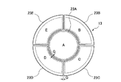
セラミックス基材の分割の形態は、中央部とその外周部の2分割に限られない。例えば、基板5の周囲やセラミックスヒータ周囲の温度環境に応じて分割できる。例えば、円盤状のセラミックス基材を周方向に(放射線状に)分割してもよいし、径方向に分割してもよい。また、分割数も限定されない。図4に示すセラミックスヒータ13のように、径方向の2分割と周方向方向の4分割(放射線状に4分割)とを組み合わせて、セラミックス基材を5つの領域に分割し、複数のセラミックス基材23A〜23Eとしてもよい。そして、各セラミックス基材23A〜23Eの間に所定のギャップを設けて配置してもよい。この場合、各セラミックス基材23A〜23Eにそれぞれ独立した端子を有する抵抗加熱体A〜Eを設けてもよい。
(Other embodiments)
The form of division of the ceramic substrate is not limited to two divisions of the central portion and the outer peripheral portion thereof. For example, it can be divided according to the temperature environment around the substrate 5 or around the ceramic heater. For example, a disk-shaped ceramic substrate may be divided in the circumferential direction (radially) or in the radial direction. Further, the number of divisions is not limited. As in the ceramic heater 13 shown in FIG. 4, the ceramic base material is divided into five regions by combining two radial divisions and four circumferential divisions (four radial divisions). It is good also as material 23A-23E. And you may arrange | position by providing a predetermined gap between each ceramic base material 23A-23E. In this case, each of the ceramic base materials 23A to 23E may be provided with resistance heating bodies A to E having independent terminals.

また、第1〜第3の実施の形態では、基材としてセラミックスを使用したセラミックスヒータの例を示したが、基材の種類はセラミックスに限られず、アルミニウムやステンレス等の金属の基材や、樹脂の基材などを使用してもよい。金属を基材として使用する場合に、金属基材中に抵抗発熱体を埋設するときは、抵抗発熱体を絶縁材で被覆することで、抵抗発熱体と金属基材との絶縁を確保するとよい。   In the first to third embodiments, examples of ceramic heaters using ceramics as a base material have been shown. However, the type of base material is not limited to ceramics, and a metal base material such as aluminum or stainless steel, A resin base material or the like may be used. When using a metal as a base material, when embedding a resistance heating element in a metal base material, it is good to ensure insulation between the resistance heating element and the metal base material by covering the resistance heating element with an insulating material. .

セラミックスヒータの各セラミックス基材の温度制御は、例えば、図5(a)、図6(a)に示すセラミックスヒータ14,15のように行うことができる。図5(a)に示すように、セラミックスヒータ14では、セラミックスヒータ11と同様に、各セラミックス基材21A、22Bそれぞれが、独立した端子を持つ抵抗発熱体30、31を備える。更に、セラミックスヒータ14は、セラミックス基材21A、21B毎に、セラミックス基材21A、21B毎の温度測定部である熱電対61,62を備える。また、セラミックスヒータ14は、セラミックス基材21A、21B毎に温度を調整するセラミックス基材21A,21B毎の温度制御装置130,131を備える。   The temperature control of each ceramic substrate of the ceramic heater can be performed, for example, like the ceramic heaters 14 and 15 shown in FIGS. 5 (a) and 6 (a). As shown in FIG. 5A, in the ceramic heater 14, like the ceramic heater 11, each ceramic base material 21 </ b> A, 22 </ b> B includes resistance heating elements 30, 31 having independent terminals. Furthermore, the ceramic heater 14 includes thermocouples 61 and 62 that are temperature measuring units for the ceramic base materials 21A and 21B, for each of the ceramic base materials 21A and 21B. The ceramic heater 14 includes temperature control devices 130 and 131 for the ceramic base materials 21A and 21B that adjust the temperature for the ceramic base materials 21A and 21B.

温度制御装置130,131はそれぞれ、温度コントローラ110,111と、出力ユニット120,121を備える。セラミックス基材21Aの温度制御装置130は、抵抗発熱体30と熱電対61に接続し、セラミックス基材21Aの温度を調整する。セラミックス基材21Bの温度制御装置131は、抵抗発熱体31と熱電対62に接続し、セラミックス基材21Bの温度を調整する。具体的には、温度コントローラ110,111が、測定温度と設定温度に応じて出力ユニット120,121から出力する電流値を制御する。出力ユニット120,121は、制御された電流値を抵抗発熱体30,31に供給する。   The temperature control devices 130 and 131 include temperature controllers 110 and 111 and output units 120 and 121, respectively. The temperature control device 130 for the ceramic substrate 21A is connected to the resistance heating element 30 and the thermocouple 61 to adjust the temperature of the ceramic substrate 21A. The temperature control device 131 of the ceramic substrate 21B is connected to the resistance heating element 31 and the thermocouple 62, and adjusts the temperature of the ceramic substrate 21B. Specifically, the temperature controllers 110 and 111 control the current values output from the output units 120 and 121 according to the measured temperature and the set temperature. The output units 120 and 121 supply the controlled current value to the resistance heating elements 30 and 31.

この場合、各セラミックス基材21A、21Bにおいて独立した温度制御が可能となる。また、セラミックス基材21A、21Bごとに熱電対61,62により温度をモニターできる。例えば、図5(b)に示すように、セラミックス基材21Aの温度Tc1を354℃に設定し、セラミックス基材21Bの温度Tc2を310℃に設定することができる。あるいはセラミックスヒータ14を用いる装置内の条件に従って、温度条件を変更することができる。このようにセラミックス基材毎の温度設定が可能になる。   In this case, independent temperature control is possible in each ceramic substrate 21A, 21B. Further, the temperature can be monitored by the thermocouples 61 and 62 for each of the ceramic base materials 21A and 21B. For example, as shown in FIG. 5B, the temperature Tc1 of the ceramic substrate 21A can be set to 354 ° C., and the temperature Tc2 of the ceramic substrate 21B can be set to 310 ° C. Alternatively, the temperature condition can be changed according to the conditions in the apparatus using the ceramic heater 14. Thus, the temperature setting for each ceramic substrate becomes possible.

また、図6(a)に示すように、セラミックスヒータ15では、セラミックスヒータ11と同様に、各セラミックス基材21A、22Bそれぞれが、独立した端子を持つ抵抗発熱体30、31を備える。このとき、一方のセラミックス基材は、温度を測定して温度制御を行い、他方のセラミックス基材は、その温度制御に応じた制御を行うことができる。具体的には、セラミックス基材21Aの温度を測定する熱電対61と、抵抗発熱体30と温度測定部である熱電対61に接続し、セラミックス基材21Aの温度を制御する主温度制御装置140を備えることができる。主温度制御装置140は、主温度コントローラ112と出力ユニット122とを備える。主温度コントローラ112が、測定温度と設定温度に応じて出力ユニット122から出力する電流値を制御する。出力ユニット122は、制御された電流値を抵抗発熱体30に供給する。このように、セラミックスヒータ15は、基材ごとの温度測定部と、抵抗発熱体と温度測定部に接続し、基材ごとに温度を調整する基材ごとの主温度制装置を少なくとも1つ備えることができる。   In addition, as shown in FIG. 6A, in the ceramic heater 15, like the ceramic heater 11, each ceramic base material 21A, 22B includes resistance heating elements 30, 31 having independent terminals. At this time, the temperature of one ceramic substrate can be measured to control the temperature, and the other ceramic substrate can be controlled according to the temperature control. Specifically, a thermocouple 61 that measures the temperature of the ceramic substrate 21A, and the main temperature control device 140 that is connected to the resistance heating element 30 and the thermocouple 61 that is a temperature measurement unit and controls the temperature of the ceramic substrate 21A. Can be provided. The main temperature control device 140 includes a main temperature controller 112 and an output unit 122. The main temperature controller 112 controls the current value output from the output unit 122 according to the measured temperature and the set temperature. The output unit 122 supplies the controlled current value to the resistance heating element 30. Thus, the ceramic heater 15 includes at least one main temperature control device for each base material that is connected to the temperature measurement unit for each base material, the resistance heating element, and the temperature measurement unit, and adjusts the temperature for each base material. be able to.

そして、セラミックス基材21Bは、熱電対を備えず、主温度制御装置140の温度制御条件に応じて温度制御条件を設定する従温度制御装置141を備える。即ち、セラミックスヒータ15は、主温度制御装置140による温度調整を受けないセラミックス基材21Bの温度を、主温度制御装置140の温度調整条件に応じて調整する従温度制御装置141を備える。   The ceramic substrate 21 </ b> B includes a sub-temperature control device 141 that does not include a thermocouple and sets temperature control conditions according to the temperature control conditions of the main temperature control device 140. That is, the ceramic heater 15 includes a sub-temperature control device 141 that adjusts the temperature of the ceramic substrate 21B that is not subjected to temperature adjustment by the main temperature control device 140 according to the temperature adjustment conditions of the main temperature control device 140.

従温度制御装置141は抵抗発熱体31に接続された出力ユニット123と、出力ユニット123と主温度コントローラ112に接続された従温度コントローラ113とを備える。従温度コントローラ113は、主温度コントローラ112の設定温度に応じて一定の関係で設定温度が決まるように設定されている。そして、従温度コントローラ113は、その設定温度に応じて出力ユニット123が出力される電流値を制御する。そして、出力ユニット123は、制御された電流値を抵抗発熱体31に供給する。   The sub-temperature control device 141 includes an output unit 123 connected to the resistance heating element 31 and a sub-temperature controller 113 connected to the output unit 123 and the main temperature controller 112. The sub-temperature controller 113 is set so that the set temperature is determined with a certain relationship according to the set temperature of the main temperature controller 112. The sub-temperature controller 113 controls the current value output from the output unit 123 according to the set temperature. Then, the output unit 123 supplies the controlled current value to the resistance heating element 31.

よって、この場合、図6(b)に示すように、モニターされるのはセラミックス基材21Aの温度Tc1のみである。そして、例えば、セラミックス基材21Bの設定温度を、常に温度Tc1から40℃低い温度に設定できる。このように、各セラミックス基材21A、21Bの設定温度が一定の関係を有するように調整する場合は、熱電対61を埋設するセラミックス基材をいずれか一つに決めて、他の基材は熱電対61が埋設されたセラミックス基材に応じて温度を調整できる。この場合は、熱電対の数を減らせるとともに、装置構成をより簡易なものにできる。   Therefore, in this case, as shown in FIG. 6B, only the temperature Tc1 of the ceramic substrate 21A is monitored. For example, the set temperature of the ceramic base material 21B can always be set to a temperature 40 ° C. lower than the temperature Tc1. Thus, when adjusting so that the set temperature of each ceramic base material 21A, 21B has a certain relationship, the ceramic base material in which the thermocouple 61 is embedded is determined as one, and the other base materials are The temperature can be adjusted according to the ceramic substrate in which the thermocouple 61 is embedded. In this case, the number of thermocouples can be reduced and the apparatus configuration can be simplified.

なお、図5(a)、図6(a)に示したような温度制御の方式は、第1〜第3の実施の形態に応用することが可能であるとともに、図4に示すようなより多くに基材を分割した場合にも適用できる。   Note that the temperature control method as shown in FIGS. 5A and 6A can be applied to the first to third embodiments and as shown in FIG. The present invention can also be applied when the substrate is divided into many parts.

更に、補助部材とセラミックス基材群の接続方法は、限定されない。例えば、図7に示すように、セラミックスヒータ16の温度が低い場合には、補助部材70とセラミックス基材群21は、Oリングや金属シール(メタルシール)などのシール部材を用いて接続できる。また、セラミックスヒータの温度がロウ付け温度以下の場合には、補助部材とセラミックス基材群は前記ロウ付けにより接続してもよい。尚、ロウ付けする位置は、例えば、図7に示したシール部材90を設ける位置と同じ位置にできる。シール部材90やロウ付けによる接続によれば、チャンバ内の腐食性ガスによる給電線や熱電対の腐食を防止できる。   Furthermore, the connection method of an auxiliary member and a ceramic base material group is not limited. For example, as shown in FIG. 7, when the temperature of the ceramic heater 16 is low, the auxiliary member 70 and the ceramic base material group 21 can be connected using a seal member such as an O-ring or a metal seal (metal seal). When the temperature of the ceramic heater is equal to or lower than the brazing temperature, the auxiliary member and the ceramic base material group may be connected by brazing. Note that the brazing position can be the same as the position where the seal member 90 shown in FIG. 7 is provided, for example. According to the connection by the seal member 90 or brazing, corrosion of the power supply line and the thermocouple due to the corrosive gas in the chamber can be prevented.

(実施例)
図2に示すセラミックスヒータ11を実施例として作製した。具体的には、還元窒化法によって得られた窒化アルミニウム粉末に、5重量%のY23を加えたセラミックス混合粉にアクリル系樹脂バインダを添加して混合し、噴霧造粒法により造粒粉を作製した。この造粒粉を金型に充填してプレスし、予備成形体を作製した。予備成形体に、転写型で抵抗発熱体を埋設する位置に溝を形成した。その溝に、図2(b)に示す巻回体に加工した線状のモリブデンの抵抗発熱体30、折り返し加工した線状のモリブデンの抵抗発熱体31を置いた。更に、その上にセラミックス原料粉を充填し、約200kg/cm2でプレスを行い、セラミックス基材21A及びセラミックス基材21Bになる成形体を作製した。これらの成形体をホットプレス焼成炉で焼成した。窒素ゲージ圧を0.5kg/cm2とする雰囲気下で、1860℃で6時間保持して焼成した。
(Example)
A ceramic heater 11 shown in FIG. 2 was produced as an example. Specifically, an acrylic resin binder is added to and mixed with an aluminum nitride powder obtained by a reduction nitriding method and mixed with a ceramic powder obtained by adding 5% by weight of Y 2 O 3, and granulated by a spray granulation method. Powder was prepared. The granulated powder was filled in a mold and pressed to prepare a preform. A groove was formed in the preform at a position where the resistance heating element was embedded in the transfer mold. In the groove, a linear molybdenum resistance heating element 30 processed into a wound body shown in FIG. 2B and a linear molybdenum resistance heating element 31 processed in a folded manner were placed. Furthermore, the ceramic raw material powder was filled thereon and pressed at about 200 kg / cm 2 , and molded bodies to be the ceramic base material 21A and the ceramic base material 21B were produced. These compacts were fired in a hot press firing furnace. Baking was performed by holding at 1860 ° C. for 6 hours in an atmosphere with a nitrogen gauge pressure of 0.5 kg / cm 2 .

円盤状のセラミックス基材21Aとして、直径100mm×厚み20mmの窒化アルミニウム焼結体を作製した。また、円環状のセラミックス基材21Bとして、内径104mm×外径310mm×厚み20mmの窒化アルミニウム焼結体を作製した。   As the disk-shaped ceramic substrate 21A, an aluminum nitride sintered body having a diameter of 100 mm and a thickness of 20 mm was produced. Further, an aluminum nitride sintered body having an inner diameter of 104 mm, an outer diameter of 310 mm, and a thickness of 20 mm was produced as the annular ceramic substrate 21B.

別途、セラミックス基材と同じ造粒粉を用いて成形し、常圧焼結して、板状の補助部材70及び管状部材41を作製した。補助部材70は、一軸方向からプレスして成形した。管状部材41は、CIP法により成形した。   Separately, it was molded using the same granulated powder as that of the ceramic base material, and sintered under normal pressure to produce a plate-like auxiliary member 70 and a tubular member 41. The auxiliary member 70 was formed by pressing from one axis direction. The tubular member 41 was formed by the CIP method.

セラミックス基材21A、22B、補助部材70、管状部材41に、ねじ穴や端子と給電線51,52との接続に必要な孔を形成した。図2(a)に示すように、セラミックス基材21A、21Bと補助部材70、補助部材70と管状部材41をそれぞれ、セラミックスのネジを用いてねじ止めした。また、抵抗発熱体30,31の端子30T1、30T2、31T1、31T2及び熱電対の端子を必要箇所にロウ付けで固定した。   The ceramic base materials 21A and 22B, the auxiliary member 70, and the tubular member 41 were formed with screw holes and holes necessary for connecting the terminals and the power supply lines 51 and 52. As shown in FIG. 2A, the ceramic base materials 21A and 21B and the auxiliary member 70, and the auxiliary member 70 and the tubular member 41 were screwed using ceramic screws. Further, the terminals 30T1, 30T2, 31T1, and 31T2 of the resistance heating elements 30 and 31 and the thermocouple terminals were fixed to necessary portions by brazing.

(比較例)
実施例と同様な製造条件を用いて、比較例のセラミックスヒータを作製した。比較例のセラミックスヒータは、セラミックス基材を一体型のものとした。ただし、セラミックス基材は中央部と外周部の2つのゾーンを持ち、それぞれに独立した端子を有する抵抗発熱体を埋設させた。各抵抗発熱体の形状は、実施例の各セラミックス基材21A、21B中に埋設されたものと同様の形状を有するようにした。
(Comparative example)
A ceramic heater of a comparative example was produced using the same production conditions as in the examples. In the ceramic heater of the comparative example, the ceramic base material was integrated. However, the ceramic base material had two zones, a central portion and an outer peripheral portion, and a resistance heating element having an independent terminal in each zone was embedded. The shape of each resistance heating element was made to have the same shape as that embedded in each ceramic substrate 21A, 21B of the example.

(評価)
実施例及び比較例の各セラミックスヒータ上に基板を載置した。基板中央部の設定温度が300℃、基板外周部の設定温度が340℃となるよう抵抗発熱体の発熱量を調整した。このときのセラミックス基材内の温度を熱電対を用いて測定した。この結果を図8に示す。なお、図8では、補助部材70や管状部材41、抵抗発熱体30,31などの図示を省略している。
(Evaluation)
The board | substrate was mounted on each ceramic heater of an Example and a comparative example. The amount of heat generated by the resistance heating element was adjusted so that the set temperature at the center of the substrate was 300 ° C. and the set temperature at the outer periphery of the substrate was 340 ° C. The temperature in the ceramic substrate at this time was measured using a thermocouple. The result is shown in FIG. In FIG. 8, the auxiliary member 70, the tubular member 41, the resistance heating elements 30, 31 and the like are not shown.

従来の一体型セラミックス基材からなる比較例のセラミックスヒータの場合は、基板温度を300℃に設定した基板中央部の真下にあたるセラミックスヒータ内部の温度は310℃であった。これに対し、基板温度を340℃に設定した基板外周部の真下にあたるセラミックスヒータ内部の温度は360℃であった。そのため、セラミックスヒータ内部では面内方向において、中央部と外周部との間に約50℃以上の温度差が生じていた。   In the case of the ceramic heater of the comparative example which consists of the conventional integrated ceramic base material, the temperature inside the ceramic heater which is just under the center part of the board | substrate which set the board | substrate temperature to 300 degreeC was 310 degreeC. On the other hand, the temperature inside the ceramic heater, which is directly below the outer periphery of the substrate where the substrate temperature was set to 340 ° C., was 360 ° C. Therefore, a temperature difference of about 50 ° C. or more has occurred between the central portion and the outer peripheral portion in the in-plane direction inside the ceramic heater.

これに対し、セラミックス基材を2分割し、ギャップを設けた実施例のセラミックスヒータ11では、セラミックス基材21Aの厚み方向のほぼ中央部において、基板温度を300℃に設定した基板中央部の真下では305℃であった。これに対し、セラミックス基材21Aの円周部では317℃であった。そのため、セラミックス基材21A内部の面内方向での温度差は12℃に過ぎなかった。また、セラミックス基材21Bにおいて、基板温度を340℃に設定した基板外周部の真下では358℃であり、セラミックス基材21B内周部での温度は350℃であった。そのため、セラミックス基材21Bの面内温度差は約10℃以下であることが確認できた。   On the other hand, in the ceramic heater 11 of the embodiment in which the ceramic base material is divided into two and provided with a gap, the substrate temperature is set just below the central portion of the substrate where the substrate temperature is set to 300 ° C. in the central portion in the thickness direction of the ceramic base material 21A. It was 305 degreeC. On the other hand, it was 317 ° C. at the circumferential portion of the ceramic substrate 21A. Therefore, the temperature difference in the in-plane direction inside the ceramic substrate 21A was only 12 ° C. Further, in the ceramic base material 21B, the temperature at the inner peripheral portion of the ceramic base material 21B was 350 ° C. immediately below the outer peripheral portion of the substrate where the substrate temperature was set to 340 ° C. Therefore, it was confirmed that the in-plane temperature difference of the ceramic substrate 21B was about 10 ° C. or less.

図8にも示されるように、従来の一体型セラミックス基材からなるセラミックスヒータに対して、複数のセラミックス基材を含むセラミックス基材群を備える実施例のセラミックスヒータ11では、各セラミックス基材21A,21Bでの面内温度差を大幅に抑制できる。そして、図8に示すように、場所によって異なる温度を設定する場合であっても、面内温度差に起因する熱応力の発生が抑制され、熱応力に起因する破損を防止できることが確認できた。   As shown also in FIG. 8, in the ceramic heater 11 of the embodiment provided with the ceramic base material group including a plurality of ceramic base materials, compared with the conventional ceramic heater made of an integrated ceramic base material, each ceramic base material 21A. , 21B, the in-plane temperature difference can be greatly suppressed. As shown in FIG. 8, it was confirmed that even when different temperatures were set depending on the location, the generation of thermal stress due to the in-plane temperature difference was suppressed, and damage due to thermal stress could be prevented. .

(a)は、本発明の第1の実施の形態に係るセラミックスヒータの断面図であり、(b)はそのセラミックス基材群の平面図である。(A) is sectional drawing of the ceramic heater which concerns on the 1st Embodiment of this invention, (b) is a top view of the ceramic base material group. (a)は、本発明の第2の実施の形態に係るセラミックスヒータの断面図であり、(b)はそのセラミックス基材群の平面図である。(A) is sectional drawing of the ceramic heater which concerns on the 2nd Embodiment of this invention, (b) is a top view of the ceramic base material group. 本発明の第3の実施の形態に係るセラミックスヒータを示す断面図である。It is sectional drawing which shows the ceramic heater which concerns on the 3rd Embodiment of this invention. 本発明の他の実施の形態に係るセラミックスヒータのセラミックス基材群の分割形態例を示す平面図である。It is a top view which shows the example of a division | segmentation form of the ceramic base material group of the ceramic heater which concerns on other embodiment of this invention. (a)は、本発明の他の実施の形態に係るセラミックスヒータを示す図であり、(b)はその温度制御例を示すグラフである。(A) is a figure which shows the ceramic heater which concerns on other embodiment of this invention, (b) is a graph which shows the temperature control example. (a)は、本発明の他の実施の形態に係るセラミックスヒータを示す図であり、(b)はその温度制御例を示すグラフである。(A) is a figure which shows the ceramic heater which concerns on other embodiment of this invention, (b) is a graph which shows the temperature control example. 本発明の他の実施の形態に係るセラミックスヒータを示す断面図である。It is sectional drawing which shows the ceramic heater which concerns on other embodiment of this invention. 本発明の実施例のセラミックスヒータ及び比較例のセラミックスヒータにおける面内温度分布測定結果を示す図である。It is a figure which shows the in-plane temperature distribution measurement result in the ceramic heater of the Example of this invention, and the ceramic heater of a comparative example.

符号の説明Explanation of symbols

10,11,12,13,14,15,16…セラミックスヒータ
10a,11a…基板載置面
20,21,22…セラミックス基材群
20A,20B,21A,21B,22A,22B,23A〜23E…セラミックス基材
30,31…抵抗発熱体
30T1,30T2,31T1,31T2…端子
31…抵抗発熱体
40,41…管状部材
50,51,52…給電線
61,62…熱電対
70,71…補助部材
80A…静電チャック電極
90…シール部材
110,111…温度コントローラ
112…主温度コントローラ
113…従温度コントローラ
120,121,122,123…出力ユニット
130,131…温度制御装置
140…主温度制御装置
141…従温度制御装置
10, 11, 12, 13, 14, 15, 16 ... ceramic heaters 10a, 11a ... substrate mounting surface 20, 21, 22 ... ceramic substrate group 20A, 20B, 21A, 21B, 22A, 22B, 23A-23E ... Ceramic substrate 30, 31 ... Resistance heating element 30T1, 30T2, 31T1, 31T2 ... Terminal 31 ... Resistance heating element 40, 41 ... Tubular member 50, 51, 52 ... Feed line 61, 62 ... Thermocouple 70, 71 ... Auxiliary member 80A ... Electrostatic chuck electrode 90 ... Sealing member 110, 111 ... Temperature controller 112 ... Main temperature controller 113 ... Sub temperature controller 120, 121, 122, 123 ... Output unit 130, 131 ... Temperature control device 140 ... Main temperature control device 141 ... Sub-temperature controller

Claims (17)

ギャップを介して略板状になるように配置され、基板載置面を形成する複数の基材を含む基材群と、
記基材ごとに設けられた、端子を持つ抵抗発熱体と
を備え
前記複数の基材には、温度を測定して温度制御が行われる一方の基材と、該一方の基材の温度制御に応じた制御が行われる他方の基材とがあり、
前記一方の基材の温度を測定する温度測定部と該基材に設けられた抵抗発熱体の端子とに接続され、前記温度測定部の測定温度と設定温度とに応じて前記抵抗発熱体に出力する電流値を制御する主温度制御装置と、
前記他方の基材に設けられた抵抗発熱体と前記主温度制御装置とに接続され、前記主温度制御装置の設定温度に応じて一定の関係で設定温度が決まるように設定され、該設定温度に応じて前記抵抗発熱体に出力する電流値を制御する従温度制御装置と、
を備えることを特徴とする基板加熱装置。
A base material group including a plurality of base materials arranged so as to be substantially plate-like via a gap and forming a substrate placement surface;
Provided for each front Kimotozai, and a resistance heating element having a terminal,
The plurality of base materials include one base material on which temperature control is performed by measuring temperature, and the other base material on which control according to the temperature control of the one base material is performed,
The resistance heating element is connected to a temperature measurement unit that measures the temperature of the one substrate and a terminal of the resistance heating element provided on the substrate, and is connected to the resistance heating element according to a measurement temperature and a set temperature of the temperature measurement unit. A main temperature control device for controlling the output current value;
It is connected to the resistance heating element provided on the other base material and the main temperature control device, and is set so that the set temperature is determined in a fixed relationship according to the set temperature of the main temperature control device, the set temperature A sub-temperature control device for controlling a current value output to the resistance heating element according to
Substrate heating apparatus comprising: a.
前記基材は、セラミックスを含むことを特徴とする請求項1に記載の基板加熱装置。   The substrate heating apparatus according to claim 1, wherein the base material includes ceramics. 前記抵抗発熱体は、前記基材に埋設されていることを特徴とする請求項1又は2に記載の基板加熱装置。   The substrate heating apparatus according to claim 1, wherein the resistance heating element is embedded in the base material. 前記ギャップの幅は、0.1mm以上10mm以下であることを特徴とする請求項1乃至のいずれか1項に記載の基板加熱装置。 The width of the gap, the substrate heating apparatus according to any one of claims 1 to 3, characterized in that a 0.1mm 10mm or more or less. 前記基材群は、第1基材と、該第1基材の外周囲に配置される環状の第2基材とを含むことを特徴とする請求項1乃至のいずれか1項に記載の基板加熱装置。 The said base material group contains a 1st base material and the cyclic | annular 2nd base material arrange | positioned at the outer periphery of this 1st base material, The any one of Claims 1 thru | or 4 characterized by the above-mentioned. Substrate heating device. 前記基材群の前記基板載置面と反対の面に接して配置される、板状の補助部材を備えることを特徴とする請求項1乃至のいずれか1項に記載の基板加熱装置。 It is disposed in contact with the opposite surface and the substrate mounting surface of the base group, a substrate heating apparatus according to any one of claims 1 to 5, characterized in that it comprises a plate-shaped auxiliary member. 前記補助部材は、絶縁性であることを特徴とする請求項に記載の基板加熱装置。 The substrate heating apparatus according to claim 6 , wherein the auxiliary member is insulative. 前記抵抗発熱体の端子に接続し、前記基材と前記補助部材の間に配線された給電線を備えることを特徴とする請求項に記載の基板加熱装置。 The substrate heating apparatus according to claim 7 , further comprising a power supply line connected to a terminal of the resistance heating element and wired between the base material and the auxiliary member. 前記補助部材は、セラミックスを含むことを特徴とする請求項又はに記載の基板加熱装置。 Said auxiliary member is a substrate heating apparatus according to claim 7 or 8, characterized in that it comprises a ceramic. 前記基材群の前記基板載置面と反対の面の中央部に直接又は間接に接続された管状部材を備えることを特徴とする請求項1乃至のいずれか1項に記載の基板加熱装置。 The substrate heating apparatus according to any one of claims 1 to 9 , further comprising a tubular member connected directly or indirectly to a central portion of a surface opposite to the substrate mounting surface of the base material group. . 前記基材群の前記基板載置面と反対の面の中央部に直接又は間接に接続された管状部材を備え、
前記管状部材は、前記補助部材を介して、前記基材群の前記基板載置面と反対の面の中央部に接続されていることを特徴とする請求項6乃至9のいずれか1項に記載の基板加熱装置。
A tubular member connected directly or indirectly to the center of the surface of the base group opposite to the substrate mounting surface;
The said tubular member is connected to the center part of the surface on the opposite side to the said substrate mounting surface of the said base material group through the said auxiliary member, The one of Claim 6 thru | or 9 characterized by the above-mentioned. The substrate heating apparatus as described.
前記管状部材は、金属又はセラミックスの少なくとも1つを含むことを特徴とする請求項10又は11に記載の基板加熱装置。 The substrate heating apparatus according to claim 10 or 11 , wherein the tubular member includes at least one of metal and ceramics. 前記補助部材と前記管状部材は、セラミックス一体焼結体であることを特徴とする請求項11に記載の基板加熱装置。 The substrate heating apparatus according to claim 11 , wherein the auxiliary member and the tubular member are ceramics integrated sintered bodies. 前記基材中に埋設された、静電チャック電極又は高周波電極の少なくとも1つを備えることを特徴とする請求項1乃至13のいずれか1項に記載の基板加熱装置。 Substrate heating apparatus according to any one of claims 1 to 13, characterized in that it comprises at least one of said embedded in the substrate, the electrostatic chuck electrode or a high frequency electrode. 前記基材は、窒化アルミニウムを含むことを特徴とする請求項乃至14のいずれか1項に記載の基板加熱装置。 The substrate is a substrate heating apparatus according to any one of claims 1 to 14, characterized in that it comprises aluminum nitride. 前記抵抗発熱体は、モリブデンまたはタングステンの少なくとも1つを含むことを特徴とする請求項1乃至15のいずれか1項に記載の基板加熱装置。 The resistive heating element, a substrate heating apparatus according to any one of claims 1 to 15, characterized in that it comprises at least one of molybdenum or tungsten. 前記抵抗発熱体の端子に接続し、ニッケルまたはアルミニウムの少なくとも1つを含む給電線を備えることを特徴とする請求項1乃至16のいずれか1項に記載の基板加熱装置。 The substrate heating apparatus according to any one of claims 1 to 16 , further comprising a power supply line connected to a terminal of the resistance heating element and including at least one of nickel and aluminum.
JP2005183921A 2004-06-28 2005-06-23 Substrate heating device Active JP4931376B2 (en)

Priority Applications (1)

Application Number Priority Date Filing Date Title
JP2005183921A JP4931376B2 (en) 2004-06-28 2005-06-23 Substrate heating device

Applications Claiming Priority (3)

Application Number Priority Date Filing Date Title
JP2004189961 2004-06-28
JP2005183921A JP4931376B2 (en) 2004-06-28 2005-06-23 Substrate heating device

Publications (2)

Publication Number Publication Date
JP2006049844A JP2006049844A (en) 2006-02-16
JP4931376B2 true JP4931376B2 (en) 2012-05-16

Family

ID=36027988

Family Applications (1)

Application Number Title Priority Date Filing Date
JP2005183921A Active JP4931376B2 (en) 2004-06-28 2005-06-23 Substrate heating device

Country Status (1)

Country Link
JP (1) JP4931376B2 (en)

Families Citing this family (12)

* Cited by examiner, † Cited by third party
Publication number Priority date Publication date Assignee Title
JP4703442B2 (en) * 2006-03-14 2011-06-15 日本碍子株式会社 Substrate heating device
JP5367232B2 (en) * 2007-03-29 2013-12-11 株式会社日本セラテック Ceramic heater
JP5009064B2 (en) * 2007-06-27 2012-08-22 太平洋セメント株式会社 Ceramic heater
JP2009043589A (en) * 2007-08-09 2009-02-26 Sei Hybrid Kk Heater unit for semiconductor or flat panel display manufacturing-inspecting device, and device equipped with the same
JP5791412B2 (en) * 2010-07-26 2015-10-07 日本碍子株式会社 Ceramic heater
JP2012080103A (en) * 2010-10-01 2012-04-19 Ngk Insulators Ltd Susceptor and manufacturing method therefor
JP2012160368A (en) * 2011-02-01 2012-08-23 Nihon Ceratec Co Ltd Ceramic heater and method for manufacturing the same
JP6100672B2 (en) 2013-10-25 2017-03-22 東京エレクトロン株式会社 Temperature control mechanism, temperature control method, and substrate processing apparatus
JP6979279B2 (en) * 2017-04-10 2021-12-08 日本特殊陶業株式会社 Holding device
JP7030420B2 (en) * 2017-04-10 2022-03-07 日本特殊陶業株式会社 Holding device
JP7317506B2 (en) * 2019-01-07 2023-07-31 日本特殊陶業株式会社 holding device
JP7240341B2 (en) 2020-02-03 2023-03-15 日本碍子株式会社 Ceramic heater and thermocouple guide

Family Cites Families (7)

* Cited by examiner, † Cited by third party
Publication number Priority date Publication date Assignee Title
US5059770A (en) * 1989-09-19 1991-10-22 Watkins-Johnson Company Multi-zone planar heater assembly and method of operation
JPH06294585A (en) * 1993-04-06 1994-10-21 Materuzu:Kk Vertical steep temperature-gradient type electric furnace
JPH11214279A (en) * 1998-01-21 1999-08-06 Sony Corp Substrate heating apparatus
JP2002184558A (en) * 2000-12-12 2002-06-28 Ibiden Co Ltd Heater
JP2002329567A (en) * 2001-05-02 2002-11-15 Ibiden Co Ltd Ceramic substrate and method of manufacturing junction body
JP3825277B2 (en) * 2001-05-25 2006-09-27 東京エレクトロン株式会社 Heat treatment device
JP2004023049A (en) * 2002-06-20 2004-01-22 Hitachi Kokusai Electric Inc Heat treatment equipment

Also Published As

Publication number Publication date
JP2006049844A (en) 2006-02-16

Similar Documents

Publication Publication Date Title
JP4931376B2 (en) Substrate heating device
KR100708568B1 (en) Substrate heating apparatus
JP4761723B2 (en) Substrate heating device
KR100709536B1 (en) Systems for heating wafers
US9698074B2 (en) Heated substrate support with temperature profile control
US20060021705A1 (en) Substrate mounting apparatus and control method of substrate temperature
JP4531004B2 (en) Heating device
US20050173410A1 (en) Ceramic heaters
JP2008243990A (en) Substrate heating device
US6806443B2 (en) Ceramic susceptor
US7394043B2 (en) Ceramic susceptor
WO2003046957A1 (en) Heated vacuum support apparatus
JP4662725B2 (en) Substrate heating apparatus and manufacturing method thereof
WO2019008889A1 (en) Substrate mounting stand for heating semiconductor substrate
WO2018230232A1 (en) Wafer heating heater and semiconductor manufacturing device
JP2005243243A (en) Heating method
US20230380017A1 (en) Ceramic heater
JP2006286646A (en) Ceramic heater
JP2013069641A (en) Ceramics heater

Legal Events

Date Code Title Description
A621 Written request for application examination

Free format text: JAPANESE INTERMEDIATE CODE: A621

Effective date: 20080215

RD02 Notification of acceptance of power of attorney

Free format text: JAPANESE INTERMEDIATE CODE: A7422

Effective date: 20090629

RD04 Notification of resignation of power of attorney

Free format text: JAPANESE INTERMEDIATE CODE: A7424

Effective date: 20090715

A977 Report on retrieval

Free format text: JAPANESE INTERMEDIATE CODE: A971007

Effective date: 20111013

A131 Notification of reasons for refusal

Free format text: JAPANESE INTERMEDIATE CODE: A131

Effective date: 20111018

A521 Written amendment

Free format text: JAPANESE INTERMEDIATE CODE: A523

Effective date: 20111202

TRDD Decision of grant or rejection written
A01 Written decision to grant a patent or to grant a registration (utility model)

Free format text: JAPANESE INTERMEDIATE CODE: A01

Effective date: 20120214

A01 Written decision to grant a patent or to grant a registration (utility model)

Free format text: JAPANESE INTERMEDIATE CODE: A01

A61 First payment of annual fees (during grant procedure)

Free format text: JAPANESE INTERMEDIATE CODE: A61

Effective date: 20120214

R150 Certificate of patent or registration of utility model

Ref document number: 4931376

Country of ref document: JP

Free format text: JAPANESE INTERMEDIATE CODE: R150

Free format text: JAPANESE INTERMEDIATE CODE: R150

FPAY Renewal fee payment (event date is renewal date of database)

Free format text: PAYMENT UNTIL: 20150224

Year of fee payment: 3