JP4928331B2 - Shell outer ring manufacturing method and shell needle roller bearing - Google Patents
Shell outer ring manufacturing method and shell needle roller bearing Download PDFInfo
- Publication number
- JP4928331B2 JP4928331B2 JP2007095967A JP2007095967A JP4928331B2 JP 4928331 B2 JP4928331 B2 JP 4928331B2 JP 2007095967 A JP2007095967 A JP 2007095967A JP 2007095967 A JP2007095967 A JP 2007095967A JP 4928331 B2 JP4928331 B2 JP 4928331B2
- Authority
- JP
- Japan
- Prior art keywords
- cup
- shaped member
- outer ring
- wall
- shell
- Prior art date
- Legal status (The legal status is an assumption and is not a legal conclusion. Google has not performed a legal analysis and makes no representation as to the accuracy of the status listed.)
- Active
Links
Images


Landscapes
- Rolling Contact Bearings (AREA)
Description
この発明は、製造工数を削減したシェル外輪の製造方法、およびこのような方法で製造されたシェル外輪を採用したシェル型針状ころ軸受に関するものである。 The present invention relates to a method for manufacturing a shell outer ring with reduced manufacturing steps, and a shell needle roller bearing that employs a shell outer ring manufactured by such a method.
従来のシェル型針状ころ軸受は、例えば、特開2003−4051号公報(特許文献1)に記載されている。同公報に記載されているシェル型針状ころ軸受は、円筒形状のシェル外輪と、シェル外輪の内径面に沿って配置されている複数の針状ころと、隣接する針状ころの間隔を保持する保持器とを備える。 A conventional shell needle roller bearing is described in, for example, Japanese Patent Application Laid-Open No. 2003-4051 (Patent Document 1). The shell-type needle roller bearing described in the publication maintains a space between a cylindrical shell outer ring, a plurality of needle rollers arranged along the inner diameter surface of the shell outer ring, and adjacent needle rollers. A retainer.
また、同公報に記載されているシェル外輪は、深絞り加工によって平板からカップ状部材を得る工程と、所定の外径を有するしごきパンチをカップ状部材の底部に当接するまで挿入する工程と、カップ状部材の外径寸法と実質的に等しい内径寸法を有するダイスにカップ状部材を圧入する工程と、しごきパンチをカップ状部材から引き抜くことによりしごき加工を行う工程とを経て製造される。そして、この方法で製造されたシェル外輪の内径面は平滑な状態になっていると記載されている。
上記の方法では、カップ状部材の外側壁を拘束した状態でしごきパンチを引き抜く。このため、加工時の面圧が高くなりすぎて、軌道面となる内側壁に傷を生じたり、しごきパンチが焼きついたりする等のトラブルが発生するおそれがある。 In the above method, the ironing punch is pulled out in a state where the outer wall of the cup-shaped member is constrained. For this reason, the surface pressure at the time of processing becomes too high, and there is a possibility that troubles such as scratches on the inner side wall serving as the raceway surface or burning of the ironing punch may occur.
一方、カップ状部材の内側壁を平滑にする他の方法として研削加工が挙げられる。しかし、研削加工だけでは軌道面となる内側壁に必要な表面粗さを得るのは難しい。また、軌道面と針状ころとの間の油膜形成能力を向上させる観点からは、内側壁にアヤメ状の加工目を形成するのが望ましい。そこで、研削加工に加えて超仕上げ加工を施す必要がある。その結果、加工工数および加工時間の増加を招き、製造コストが上昇する。 On the other hand, as another method for smoothing the inner side wall of the cup-shaped member, there is a grinding process. However, it is difficult to obtain the required surface roughness on the inner wall serving as the raceway surface by grinding alone. Further, from the viewpoint of improving the oil film forming ability between the raceway surface and the needle rollers, it is desirable to form iris-like processed stitches on the inner wall. Therefore, it is necessary to perform super finishing in addition to grinding. As a result, processing man-hours and processing time are increased, and manufacturing costs are increased.
そこで、この発明の目的は、製造コストを低減し、傷や焼き付き等のトラブルを防止して平滑な軌道面を得ることができるシェル外輪の製造方法を提供することである。 Accordingly, an object of the present invention is to provide a method for manufacturing a shell outer ring that can reduce the manufacturing cost, prevent troubles such as scratches and burn-in, and obtain a smooth raceway surface.
この発明は、円環形状の内径面に軌道面を有するシェル外輪の製造方法である。具体的には、絞り加工によって平板からカップ状部材を得る工程と、完成品であるシェル外輪の内径面と一致する円柱状部材であって、先端が径方向外側に突出しカップ状部材の内側壁より直径の小さい雄冶具をカップ状部材の内底壁に当接するまで挿入する工程と、カップ状部材の外側壁より直径が小さく、完成品であるシェル外輪の外径面の直径に一致する雌冶具にカップ状部材を圧入してしごき加工し、塑性変形により、カップ状部材の内側壁を雄冶具に沿った形状とし、カップ状部材の外側壁を雌冶具に沿った形状とする工程と、カップ状部材と雄冶具との相対位置を変更することなく、カップ状部材を雌冶具から引き抜く工程と、雌冶具から引き抜く工程の後に、雄冶具をカップ状部材から引き抜いて内側壁を表面しごき加工する工程とを含む。
The present invention is a method for manufacturing a shell outer ring having a raceway surface on an annular inner diameter surface. Specifically, a step of obtaining a cup-shaped member from a flat plate by drawing and a columnar member that coincides with the inner diameter surface of the shell outer ring that is a finished product, the tip projecting radially outward and the inner wall of the cup-shaped member Inserting a male jig having a smaller diameter until it abuts against the inner bottom wall of the cup-shaped member, and a female having a diameter smaller than the outer wall of the cup-shaped member and matching the diameter of the outer diameter surface of the shell outer ring as a finished product. A step of pressing and inserting a cup-shaped member into a jig, and plastically deforming the inner wall of the cup-shaped member along the male jig, and forming the outer wall of the cup-shaped member along the female jig ; Without changing the relative position of the cup-shaped member and the male jig , after the process of pulling the cup-shaped member out of the female jig and the process of pulling out from the female jig, the male jig is pulled out of the cup-shaped member and the inner side wall is squeezed. Do And a degree.
上記の製造工程において、圧入工程では、カップ状部材をしごき加工することにより、カップ状部材の内側壁は雄冶具の外径に沿った形状となる。また、内側壁の表面しごき加工工程では、カップ状部材の外側壁を拘束しない状態で雄冶具をカップ状部材から引き抜く。このとき、雄冶具の先端部に接触する側壁は、径方向外側に弾性変形することができる。その結果、面圧の上昇に伴う傷や焼き付き等のトラブルの発生を防止することができる。 In the above manufacturing process, in the press-fitting process, the inner wall of the cup-shaped member is shaped along the outer diameter of the male jig by ironing the cup-shaped member. Further, in the surface ironing process of the inner wall, the male jig is pulled out from the cup-shaped member without restraining the outer wall of the cup-shaped member. At this time, the side wall contacting the tip of the male jig can be elastically deformed radially outward. As a result, it is possible to prevent the occurrence of troubles such as scratches and burn-in due to an increase in surface pressure.
また、上記の方法で表面しごき加工を行うことにより、軌道面となる内側壁に軸線方向に平行な加工目が形成される。これにより、軌道面と針状ころとの間の油膜形成性が向上する。このようなシェル外輪を採用することにより、潤滑性能に優れたシェル型針状ころ軸受を得ることができる。 Further, by performing the surface ironing process by the above method, a processing line parallel to the axial direction is formed on the inner wall serving as the raceway surface. Thereby, the oil film formation property between a raceway surface and a needle roller improves. By adopting such a shell outer ring, it is possible to obtain a shell needle roller bearing with excellent lubrication performance.
なお、本明細書中「外底壁」とは、カップ状部材の外側の底壁面を指す。同様に「内底壁」とは、カップ状部財の内側の底壁面を指す。さらに「底壁」という場合は、内底壁と外底壁とを含むカップ状部材の底部分全体を指すものとする。また、「側壁」、「内側壁」、および「外側壁」の語についても同様である。 In the present specification, the “outer bottom wall” refers to the bottom wall surface outside the cup-shaped member. Similarly, the “inner bottom wall” refers to the bottom wall surface inside the cup-shaped component. Furthermore, the “bottom wall” refers to the entire bottom portion of the cup-shaped member including the inner bottom wall and the outer bottom wall. The same applies to the terms “side wall”, “inner side wall”, and “outer wall”.
また、本明細書中「しごき加工」とは、被加工部材の板厚を減少させながら行う絞り加工を指すものとする。一方、「表面しごき加工」とは、被加工部材を弾性変形可能な状態で保持してしごき加工を行うことによって、加工面を平滑にする加工を指すものとし、表面しごき加工によっては被加工部材の板厚はほとんど変化しない点で、上記のしごき加工とは異なる。 In the present specification, the “scoring process” refers to a drawing process performed while reducing the plate thickness of the workpiece. On the other hand, “surface ironing” refers to the process of smoothing the processed surface by holding the workpiece in an elastically deformable state and performing the ironing, and depending on the surface ironing, the workpiece This is different from the ironing process described above in that the thickness of the plate hardly changes.
好ましくは、シェル外輪の軌道面の表面粗さRaは0.1μm以下である。軌道面の表面粗さを0.1μm以下とすることにより、針状ころの回転がスムーズになる。なお、本明細書中「表面粗さRa」とは、算術平均粗さであって、粗さ曲線から平均線の方向に基準長さだけ抜き取り、この抜き取り部分の平均線から測定曲線までの偏差の絶対値を合計し平均した値とする。 Preferably, the surface roughness Ra of the raceway surface of the shell outer ring is 0.1 μm or less. By setting the surface roughness of the raceway surface to 0.1 μm or less, the needle rollers rotate smoothly. In the present specification, “surface roughness Ra” is an arithmetic average roughness, which is extracted from the roughness curve by a reference length in the direction of the average line, and the deviation from the average line of the extracted portion to the measurement curve. The absolute values of these are summed and averaged.
この発明に係るシェル型針状ころ軸受は、上記の製造方法によって製造されるシェル外輪と、シェル外輪の軌道面に沿って配置される複数の針状ころとを備える。上記方法でシェル外輪を製造することにより、平滑な軌道面を得ることができる。その結果、針状ころがスムーズに回転可能なシェル型針状ころ軸受を得ることができる。 A shell needle roller bearing according to the present invention includes a shell outer ring manufactured by the above-described manufacturing method, and a plurality of needle rollers arranged along a raceway surface of the shell outer ring. By manufacturing the shell outer ring by the above method, a smooth raceway surface can be obtained. As a result, a shell-type needle roller bearing can be obtained in which the needle rollers can rotate smoothly.
このようなシェル外輪の製造方法によれば、雌冶具への圧入工程では、カップ状部材をしごき加工することにより、カップ状部材の内側壁は雄冶具の外径に沿った形状となる。すなわち、完成品であるシェル外輪の内径面と一致する円柱状部材である雄冶具をカップ状部材に挿入した状態で、完成品であるシェル外輪の外径面の直径に一致する雌冶具に圧入してしごき加工をすることにより、カップ状部材の内側壁を雄冶具の外径に沿った形状として、カップ状部材の内径面の寸法を完成品の内径面の寸法と同じにし、カップ状部材の外側壁を、完成品であるシェル外輪の外径面の直径に一致する雌冶具に沿った形状として、カップ状部材の外径面の寸法を完成品の外径面の寸法と同じにすることができる。また、内側壁の表面しごき加工工程では、カップ状部材の外側壁を拘束しない状態で雄冶具をカップ状部材から引き抜く。このとき、雄冶具の先端部に接触する側壁は、径方向外側に弾性変形することができる。その結果、面圧の上昇に伴う傷や焼き付き等のトラブルの発生を防止することができる。また、上記の方法で表面しごき加工を行うことにより、軌道面となる内側壁に軸線方向に平行な加工目が形成される。これにより、軌道面と針状ころとの間の油膜形成性が向上する。このようなシェル外輪を採用することにより、潤滑性能に優れたシェル型針状ころ軸受を得ることができる。また、このようなシェル外輪の製造方法によると、研削加工を含む超仕上げ加工を行う必要がないため、製造コストを低減することができる。以上より、本願発明によると、シェル外輪の製造方法において、製造コストを低減し、傷や焼き付き等のトラブルを防止して平滑な軌道面を得ることができる。According to such a manufacturing method of the shell outer ring, in the press-fitting process into the female jig, the inner wall of the cup-shaped member is shaped along the outer diameter of the male jig by ironing the cup-shaped member. In other words, with a male jig that is a cylindrical member that matches the inner diameter surface of the shell outer ring that is the finished product being inserted into the cup-like member, it is press-fitted into the female jig that matches the diameter of the outer diameter surface of the shell outer ring that is the finished product. By carrying out ironing, the inner wall of the cup-shaped member is shaped along the outer diameter of the male jig so that the inner diameter of the cup-shaped member is the same as the inner diameter of the finished product. The outer wall of the cup has a shape along the female jig that matches the diameter of the outer diameter surface of the shell outer ring as a finished product, and the outer diameter surface of the cup-shaped member is the same as the outer diameter surface of the finished product. be able to. Further, in the surface ironing process of the inner wall, the male jig is pulled out from the cup-shaped member without restraining the outer wall of the cup-shaped member. At this time, the side wall contacting the tip of the male jig can be elastically deformed radially outward. As a result, it is possible to prevent the occurrence of troubles such as scratches and burn-in due to an increase in surface pressure. Further, by performing the surface ironing process by the above method, a processing line parallel to the axial direction is formed on the inner wall serving as the raceway surface. Thereby, the oil film formation property between a raceway surface and a needle roller improves. By adopting such a shell outer ring, it is possible to obtain a shell needle roller bearing with excellent lubrication performance. Moreover, according to such a manufacturing method of a shell outer ring, since it is not necessary to perform super finishing including grinding, manufacturing cost can be reduced. As described above, according to the present invention, the manufacturing method of the shell outer ring can reduce the manufacturing cost, prevent troubles such as scratches and burn-in, and obtain a smooth raceway surface.
まず、図7を参照して、この発明の一実施形態に係るシェル型針状ころ軸受11を説明する。シェル型針状ころ軸受11は、円環形状の内径面に軌道面12aおよび軸方向両端部に径方向内側に突出する鍔部12bを有する外輪12と、外輪12の軌道面12aに沿って配置される複数の針状ころ13と、隣接する針状ころ13の間隔を保持する保持器14とを備える。
First, with reference to FIG. 7, the shell type needle roller bearing 11 which concerns on one Embodiment of this invention is demonstrated. The shell-type needle roller bearing 11 is disposed along the
次に、図1〜図6を参照して、この発明の一実施形態に係るシェル外輪12の製造方法を説明する。なお、図1はシェル外輪12の製造工程の一部を示すフロー図、図2〜図6はしごき加工工程の詳細を示す図である。
Next, with reference to FIGS. 1-6, the manufacturing method of the shell outer ring |
まず、シェル外輪12は、軸受鋼等の炭素鋼を圧延加工して得られる平板を出発材料として採用する。なお、炭素等の元素の含有量は、シェル外輪12に求められる硬さ、靭性、耐摩耗性、および加工性等の機械的性質を満足するように調整される。
First, the shell
次に、第1の工程では、絞り加工によって平板からカップ状部材21を得る(S11)。図3を参照して、カップ状部材21は、円筒形状の側壁22と、側壁22の一方側端部(図3の下側)を閉鎖する底壁23とを有する。なお、内側壁22aは針状ころ13と接触する軌道面12aとして機能する。したがって、絞り深さ(「側壁22の高さ」を指す)は針状ころ13の長さより深く設定する必要がある。また、この工程において、カップ状部材21の内側壁22aの直径は、シェル外輪12の内径面の直径より大きく設定されている。
Next, in the first step, the cup-
この絞り加工工程(S11)では、1度の絞り加工によって所定の長さの内側壁22aを得てもよいし、絞り加工を複数回繰り返してもよい。また、絞り加工工程(S11)以降、側壁22の他方側端部(図3の上側)を切り揃えるトリミング加工等が施される。
In this drawing process (S11), the
次に、第2の工程では、しごき加工によって軌道面12aとなる内側壁22aを平滑な状態にする(S12)。この工程で、内側壁22aの表面粗さRaは0.1μm以下となる。また、内側壁22aには軸線方向に平行な加工目が形成される。詳しい加工工程は後述する。
Next, in a 2nd process, the
次に、第3の工程では、底壁23を除去して円筒形状のシェル外輪12を得る(S13)。底壁23を除去する具体的な方法は特に限定されない。例えば、底壁23の中央部に貫通孔を設け、貫通孔の外周を径方向外側に向かって旋削することによって除去してもよい。または、外底壁23bの所定位置に断面がV字形状の円周溝を設け、底壁23に圧力を加えることによってV字の根元部分に応力集中を生じさせて除去してもよい。
Next, in the third step, the
次に、第4の工程では、所定の機械的性質を得るためにシェル外輪12に熱処理を施す(S14)。熱処理の具体例としては、硬さや耐摩耗性等の向上を目的として光輝焼き入れ、浸炭焼き入れ、または浸炭窒化処理等が、靭性等の向上や残留応力の除去等を目的として焼き戻しや焼鈍し等が挙げられる。
Next, in the fourth step, the shell
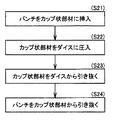
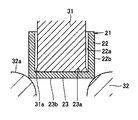
次に、図2〜図6を参照して、しごき加工工程(S12)の詳細を説明する。なお、図2はしごき加工の詳細な工程を示すフロー図、図3はパンチ31をカップ状部材21に挿入する工程を示す図、図4はカップ状部材21をダイス32に圧入する工程を示す図、図5はパンチ31をカップ状部材21から引き抜く工程を示す図、図6は図5のP部の拡大図である。また、図2〜図5は発明の理解を容易とするために、板厚を実際より厚く描いている。
Next, the details of the ironing process (S12) will be described with reference to FIGS. 2 is a flowchart showing detailed steps of the ironing process, FIG. 3 is a diagram showing a process of inserting the
まず、第1の工程では、雄冶具としてのパンチ31をカップ状部材21の内側壁22aに沿って挿入し、内底壁23aに当接させる(S21)。パンチ31の直径は、完成品であるシェル外輪12の内径面の直径と一致する円柱状部材であって、先端に径方向外側に突出する突出部31aを有する。この突出部31aの直径は、パンチ31の他の部分と比較して、すなわちシェル外輪12の内径面の直径と比較して大きく設定する。また、突出部31aの直径はカップ状部材21の内側壁22aより小さいので、挿入時にパンチ31の外径面と内側壁22aとが接触することはない。
First, in the first step, the
次に、第2の工程では、パンチ31をさらに押し下げて、カップ状部材21を雌冶具としてのダイス32に圧入する(S22)。すなわち、カップ状部材21の側壁22にしごき加工を施す。ダイス32の内径面の直径は、カップ状部材21の外側壁22bの直径より小さく、完成品であるシェル外輪12の外径面の直径に一致する。また、圧入に必要な荷重を低減する観点から、ダイス32の開口部32aは所定の曲率を有する円弧形状としている。
Next, in the second step, the
この工程においてカップ状部材21は塑性変形し、内側壁22aはパンチ31に、外側壁22bはダイス32に沿った形状となる。そして、内側壁22aおよび外側壁22bの直径は、それぞれシェル外輪12の内径面および外径面の直径と一致する。また、この工程では、カップ状部材21の板厚が薄くなる。余った肉(図示省略)は側壁22に沿ってカップ状部材21の開放側端部(図4の上方向)に移動し、トリミング加工によって切断される。
In this step, the cup-shaped
次に、第3の工程では、カップ状部材21とパンチ31との相対位置を変更することなく、ダイス32からカップ状部材21を引き抜く(S23)。なお、カップ状部材21が前の工程で塑性変形しているので、ダイス32から引き抜いても元の形状に戻ることはない。また、カップ状部材21がダイス32に嵌め込まれた状態、すなわちカップ状部材21の外側壁22bが拘束された状態でパンチ31を引き抜くと、内側壁22aに傷を生じたり、焼き付いたりするおそれがある。そこで、この工程において、カップ状部材21とパンチ31との相対位置は変更しない。
Next, in the third step, the cup-shaped
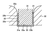
次に、第4の工程では、カップ状部材21の開口部側の端面(図5の上側)を拘束した状態で、パンチ31をカップ状部材21から引き抜く(S24)。すなわち、カップ状部材21の内側壁22aに表面しごき加工を施す。このとき、パンチ31の突出部31aがカップ状部材21の内側壁22aの表面をしごいて、表面粗さRaを0.1μm以下とすると共に、軸線方向に平行な加工目を形成する。
Next, in the fourth step, the
図6を参照して、カップ状部材21の外側壁22bは拘束されていないので、パンチ31の突出部31aに接触する側壁は、径方向外側に弾性変形することができる。これにより、面圧の上昇を抑えて内側壁22aの傷や焼き付き等のトラブルの発生を防止することができる。
Referring to FIG. 6, since the
なお、突出部31aが通過した後は元の形状に戻るので、シェル外輪12の精度には問題がない。また、しごき加工時(S22)において、カップ状部材21の突出部31aに対面していた部分には、側壁22の厚み寸法を減じるように逃げ部24が形成されている。この逃げ部24は、針状ころ13の転動面に接触しない大きさに設定する。
In addition, since it returns to the original shape after the
上記の方法によれば、側壁22を弾性変形可能な状態で表面しごき加工することにより、面圧の上昇を抑制することができる。その結果、転動面12aとなる内側壁22aに傷を生じたり、カップ状部材21とパンチ31との間で焼き付きを生じたりするのを有効に防止することができる。また、超仕上げ加工(研削加工を含む)を施す場合と比較して、低コストで同程度の表面粗さを得ることができる。
According to said method, the raise of surface pressure can be suppressed by carrying out surface ironing of the
上記の実施形態におけるシェル型針状ころ軸受11は、構成要素として保持器14を有する例を示したが、この発明において保持器14は必須の構成要素ではない。つまり、この発明は、総ころ形式のシェル型針状ころ軸受にも適用することができる。
Although the shell type
また、上記の各工程は、この発明に係るシェル外輪12の製造工程一例であって、各工程をさらに細分化してもよいし、必要な工程をさらに追加することもできる。また、加工工程の順番も任意に入れ替えることができるものとする。
Moreover, each said process is an example of the manufacturing process of the shell outer ring |
さらに、上記の各工程は、それぞれ別々の工程として単能プレスで行ってもよいが、順送プレス、または、トランスファプレスによって行うこととしてもよい。これにより、各工程を連続的に行うことができる。また、上記の各工程の全部または一部に相当する加工部を有するシェル外輪12の製造装置を使用することにより、生産性を高めることができ、結果としてシェル型針状ころ軸受11の製品価格を抑えることができる。
Furthermore, each of the above steps may be performed by a single press as a separate step, but may be performed by a progressive press or a transfer press. Thereby, each process can be performed continuously. Moreover, by using the manufacturing apparatus of the shell outer ring |
なお、本明細書中で「順送プレス」とは、プレス内に複数の加工工程を持ち、材料をプレス入口のフィーダにより各工程を移動させることによって、材料を連続的に加工する方法を指すものとする。また、本明細書中で「トランスファプレス」とは、複数の加工工程を必要とする場合に、各工程を行うステージを必要数分設け、搬送装置によって工程品を移動させながら、各ステージで加工を行う方法を指すものとする。 In the present specification, “sequential press” refers to a method of continuously processing a material by having a plurality of processing steps in the press and moving the material by a feeder at a press inlet. Shall. In addition, in this specification, “transfer press” means that when a plurality of processing steps are required, the necessary number of stages for performing each step are provided, and processing is performed at each stage while moving the process product by the transfer device. Refers to the method of performing
以上、図面を参照してこの発明の実施形態を説明したが、この発明は、図示した実施形態のものに限定されない。図示した実施形態に対して、この発明と同一の範囲内において、あるいは均等の範囲内において、種々の修正や変形を加えることが可能である。 As mentioned above, although embodiment of this invention was described with reference to drawings, this invention is not limited to the thing of embodiment shown in figure. Various modifications and variations can be made to the illustrated embodiment within the same range or equivalent range as the present invention.
この発明は、シェル型針状ころ軸受に有利に利用される。 The present invention is advantageously used for shell-type needle roller bearings.
11 シェル型針状ころ軸受、12 シェル外輪、12a 軌道面、12b 鍔部、13 針状ころ、14 保持器、21 カップ状部材、22 側壁、22a 内側壁、23 底壁、23a 内底壁、23b 外底壁、24 逃げ部、31 パンチ、31a 突出部、32 ダイス、32a 開口部。
DESCRIPTION OF
Claims (3)
絞り加工によって平板からカップ状部材を得る工程と、
完成品であるシェル外輪の内径面と一致する円柱状部材であって、先端が径方向外側に突出し前記カップ状部材の内側壁より直径の小さい雄冶具を前記カップ状部材の内底壁に当接するまで挿入する工程と、
前記カップ状部材の外側壁より直径が小さく、完成品であるシェル外輪の外径面の直径に一致する雌冶具に前記カップ状部材を圧入してしごき加工し、塑性変形により、前記カップ状部材の内側壁を前記雄冶具に沿った形状とし、前記カップ状部材の外側壁を前記雌冶具に沿った形状とする工程と、
前記カップ状部材と前記雄冶具との相対位置を変更することなく、前記カップ状部材を前記雌冶具から引き抜く工程と、
前記雌冶具から引き抜く工程の後に、前記雄冶具を前記カップ状部材から引き抜いて内側壁を表面しごき加工する工程とを含む、シェル外輪の製造方法。 A method for manufacturing a shell outer ring having a raceway surface on an annular inner diameter surface,
Obtaining a cup-shaped member from a flat plate by drawing;
A cylindrical member coinciding with the inner diameter surface of the shell outer ring, which is a finished product, and having a tip projecting radially outward and having a diameter smaller than the inner wall of the cup-shaped member is applied to the inner bottom wall of the cup-shaped member. Inserting until contact,
The cup- shaped member is pressed into a female jig having a diameter smaller than that of the outer wall of the cup-shaped member and matches the diameter of the outer diameter surface of the shell outer ring, which is a finished product, and subjected to ironing and plastic deformation. And forming the inner wall of the cup along the male jig and the outer wall of the cup-shaped member along the female jig ,
Without changing the relative position of the cup-shaped member and the male jig, the step of pulling out the cup-shaped member from the female jig;
A method of manufacturing a shell outer ring , comprising: after the step of pulling out from the female jig, pulling out the male jig from the cup-shaped member and squeezing the inner wall surface.
前記シェル外輪の軌道面に沿って配置される複数の針状ころとを備える、シェル型針状ころ軸受。
A shell outer ring manufactured by the method for manufacturing a shell outer ring according to claim 1 or 2,
A shell-type needle roller bearing comprising a plurality of needle rollers arranged along a raceway surface of the shell outer ring.
Priority Applications (1)
| Application Number | Priority Date | Filing Date | Title |
|---|---|---|---|
| JP2007095967A JP4928331B2 (en) | 2007-04-02 | 2007-04-02 | Shell outer ring manufacturing method and shell needle roller bearing |
Applications Claiming Priority (1)
| Application Number | Priority Date | Filing Date | Title |
|---|---|---|---|
| JP2007095967A JP4928331B2 (en) | 2007-04-02 | 2007-04-02 | Shell outer ring manufacturing method and shell needle roller bearing |
Publications (2)
| Publication Number | Publication Date |
|---|---|
| JP2008256005A JP2008256005A (en) | 2008-10-23 |
| JP4928331B2 true JP4928331B2 (en) | 2012-05-09 |
Family
ID=39979779
Family Applications (1)
| Application Number | Title | Priority Date | Filing Date |
|---|---|---|---|
| JP2007095967A Active JP4928331B2 (en) | 2007-04-02 | 2007-04-02 | Shell outer ring manufacturing method and shell needle roller bearing |
Country Status (1)
| Country | Link |
|---|---|
| JP (1) | JP4928331B2 (en) |
Families Citing this family (2)
| Publication number | Priority date | Publication date | Assignee | Title |
|---|---|---|---|---|
| JP5762698B2 (en) * | 2010-06-24 | 2015-08-12 | Ntn株式会社 | Split needle bearing and bearing device |
| WO2011142240A1 (en) * | 2010-05-11 | 2011-11-17 | Ntn株式会社 | Split needle bearing and lubrication device for internal combustion engine |
Family Cites Families (6)
| Publication number | Priority date | Publication date | Assignee | Title |
|---|---|---|---|---|
| JPS5847520A (en) * | 1981-09-14 | 1983-03-19 | Toyo Kohan Co Ltd | Forming method of di can |
| JPH0724872B2 (en) * | 1986-04-23 | 1995-03-22 | エヌティ・エヌ株式会社 | Method for forming outer ring of tripod type constant velocity joint |
| JPH01317638A (en) * | 1988-06-17 | 1989-12-22 | Kotani Tanko Kk | Method and device for manufacturing hub unit bearing outer ring for automobile |
| JP2515144B2 (en) * | 1988-09-23 | 1996-07-10 | 本田技研工業株式会社 | Molding method for constant velocity joint |
| DE10135588B4 (en) * | 2000-08-04 | 2011-07-07 | SKF GmbH, 97421 | bearing ring |
| JP4080182B2 (en) * | 2001-06-25 | 2008-04-23 | Ntn株式会社 | SHELL TYPE NEEDLE ROLLER BEARING AND MANUFACTURING METHOD THEREOF |
-
2007
- 2007-04-02 JP JP2007095967A patent/JP4928331B2/en active Active
Also Published As
| Publication number | Publication date |
|---|---|
| JP2008256005A (en) | 2008-10-23 |
Similar Documents
| Publication | Publication Date | Title |
|---|---|---|
| CN101910659B (en) | Retainer for roller bearing and needle roller bearing | |
| JP5464821B2 (en) | Roller bearing cage, roller bearing and roller bearing cage manufacturing method | |
| CN102537051B (en) | Drawn cup needle roller bearing having a seal ring and its manufacture method | |
| CN101910660A (en) | Retainer for roller bearing, needle-like roller bearing, and method for manufacturing retainer for roller bearing | |
| JP5408226B2 (en) | Method for manufacturing shell needle bearing with seal ring | |
| JP4080182B2 (en) | SHELL TYPE NEEDLE ROLLER BEARING AND MANUFACTURING METHOD THEREOF | |
| JP4928331B2 (en) | Shell outer ring manufacturing method and shell needle roller bearing | |
| JP2009156393A (en) | Retainer for roller bearing, and needle roller bearing | |
| JP5346465B2 (en) | Roller bearing cage and needle roller bearing | |
| JP2006250327A (en) | Thrust roller bearing, and manufacturing method for cage of thrust roller bearing | |
| JP4978318B2 (en) | Method for manufacturing shell needle bearing with seal ring | |
| JP2014029212A (en) | Retainer for pressed roller bearing, roller bearing and manufacturing method of retainer for pressed roller bearing | |
| JP5246742B2 (en) | Roller bearing cage and needle roller bearing | |
| JP2009156389A (en) | Cage for roller bearing and needle roller bearing | |
| JP2006220228A (en) | Manufacturing method for retainer of thrust roller bearing | |
| JP2008088995A (en) | Method of manufacturing bearing ring for thrust roller bearing and bearing ring forming member for thrust roller bearing | |
| JP5346471B2 (en) | Needle roller bearing | |
| JP5597747B2 (en) | Roller bearing cage and needle roller bearing | |
| JP2017187176A (en) | Shell roller bearing | |
| JP2008256004A (en) | Manufacturing method for drawn cup and shell-type needle roller bearing | |
| JP4627750B2 (en) | Roller bearing | |
| JP6290568B2 (en) | Shell roller bearing | |
| JP2009180255A (en) | Idler support structure and transmission |
Legal Events
| Date | Code | Title | Description |
|---|---|---|---|
| A621 | Written request for application examination |
Free format text: JAPANESE INTERMEDIATE CODE: A621 Effective date: 20100326 |
|
| A131 | Notification of reasons for refusal |
Free format text: JAPANESE INTERMEDIATE CODE: A131 Effective date: 20110628 |
|
| A977 | Report on retrieval |
Free format text: JAPANESE INTERMEDIATE CODE: A971007 Effective date: 20110630 |
|
| A521 | Request for written amendment filed |
Free format text: JAPANESE INTERMEDIATE CODE: A523 Effective date: 20110802 |
|
| TRDD | Decision of grant or rejection written | ||
| A01 | Written decision to grant a patent or to grant a registration (utility model) |
Free format text: JAPANESE INTERMEDIATE CODE: A01 Effective date: 20120117 |
|
| A01 | Written decision to grant a patent or to grant a registration (utility model) |
Free format text: JAPANESE INTERMEDIATE CODE: A01 |
|
| A61 | First payment of annual fees (during grant procedure) |
Free format text: JAPANESE INTERMEDIATE CODE: A61 Effective date: 20120210 |
|
| FPAY | Renewal fee payment (event date is renewal date of database) |
Free format text: PAYMENT UNTIL: 20150217 Year of fee payment: 3 |
|
| R150 | Certificate of patent or registration of utility model |
Ref document number: 4928331 Country of ref document: JP Free format text: JAPANESE INTERMEDIATE CODE: R150 Free format text: JAPANESE INTERMEDIATE CODE: R150 |
|
| R250 | Receipt of annual fees |
Free format text: JAPANESE INTERMEDIATE CODE: R250 |
|
| R250 | Receipt of annual fees |
Free format text: JAPANESE INTERMEDIATE CODE: R250 |
|
| R250 | Receipt of annual fees |
Free format text: JAPANESE INTERMEDIATE CODE: R250 |
|
| R250 | Receipt of annual fees |
Free format text: JAPANESE INTERMEDIATE CODE: R250 |
|
| R250 | Receipt of annual fees |
Free format text: JAPANESE INTERMEDIATE CODE: R250 |
|
| R250 | Receipt of annual fees |
Free format text: JAPANESE INTERMEDIATE CODE: R250 |
|
| R250 | Receipt of annual fees |
Free format text: JAPANESE INTERMEDIATE CODE: R250 |
|
| R250 | Receipt of annual fees |
Free format text: JAPANESE INTERMEDIATE CODE: R250 |
|
| R250 | Receipt of annual fees |
Free format text: JAPANESE INTERMEDIATE CODE: R250 |
|
| R250 | Receipt of annual fees |
Free format text: JAPANESE INTERMEDIATE CODE: R250 |
|
| R250 | Receipt of annual fees |
Free format text: JAPANESE INTERMEDIATE CODE: R250 |
|
| R250 | Receipt of annual fees |
Free format text: JAPANESE INTERMEDIATE CODE: R250 |