JP4926647B2 - Communication system, base station and terminal used in the communication system, and base station switching method - Google Patents
Communication system, base station and terminal used in the communication system, and base station switching method Download PDFInfo
- Publication number
- JP4926647B2 JP4926647B2 JP2006293242A JP2006293242A JP4926647B2 JP 4926647 B2 JP4926647 B2 JP 4926647B2 JP 2006293242 A JP2006293242 A JP 2006293242A JP 2006293242 A JP2006293242 A JP 2006293242A JP 4926647 B2 JP4926647 B2 JP 4926647B2
- Authority
- JP
- Japan
- Prior art keywords
- subchannel
- base station
- terminal
- switching
- communication
- Prior art date
- Legal status (The legal status is an assumption and is not a legal conclusion. Google has not performed a legal analysis and makes no representation as to the accuracy of the status listed.)
- Expired - Fee Related
Links
Images


Description
本発明は、OFDMA方式の通信システム、該通信システムに用いる基地局及び端末並びに当該通信システムにおけるハンドオーバの際の基地局切替方法に関する。 The present invention relates to an OFDMA communication system, base stations and terminals used in the communication system, and a base station switching method at the time of handover in the communication system.
PHSシステムなどの無線アクセス方式として、TDMA(Time Division Multiple Access:時分割多元接続)とTDD(Time Division Duplex:時分割双方向伝送)を組み合わせたTDMA/TDD方式が採用されている。最近では、OFDM(Orthogonal Frequency Division Multiplexing:直交周波数分割)の技術によるOFDMA(Orthogonal Frequency Division Multiplexing Access:直交周波数分割多重接続)を用いたOFDMA方式が提案されている。 As a radio access system such as a PHS system, a TDMA / TDD system in which TDMA (Time Division Multiple Access) and TDD (Time Division Duplex) are combined is adopted. Recently, an OFDMA scheme using OFDMA (Orthogonal Frequency Division Multiplexing Access) based on OFDM (Orthogonal Frequency Division Multiplexing) technology has been proposed.
OFDMは、データを変調する搬送波を、互いに直交した複数の「サブキャリア」(細分化された搬送波)に分割し、データ信号をそれぞれのサブキャリアに分散させて送信する方式である。 OFDM is a scheme in which a carrier wave that modulates data is divided into a plurality of “subcarriers” (subdivided carrier waves) orthogonal to each other, and a data signal is distributed and transmitted to each subcarrier.
以下、OFDM方式の概要について説明する。
図11は送信側に用いられるOFDM変調装置の構成を示すブロック図である。OFDM変調装置には、送信データが入力される。この送信データは、シリアル/パラレル変換部201に供給されて、低速な複数の伝送シンボルからなるデータに変換される。つまり、伝送情報を分割して、複数の低速なデジタル信号を生成する。このパラレルデータは、逆高速フーリエ変換(IFFT)部202に供給される。
Hereinafter, an outline of the OFDM scheme will be described.
FIG. 11 is a block diagram showing a configuration of an OFDM modulation apparatus used on the transmission side. Transmission data is input to the OFDM modulator. This transmission data is supplied to the serial /
パラレルデータは、OFDMを構成する各サブキャリアに割り当てられ、周波数領域においてマッピングされる。ここで、各サブキャリアに対してBPSK、QPSK、16QAM、64QAM等の変調が施される。マッピングデータは、IFFT演算を施すことによって、周波数領域の送信データから時間領域の送信データに変換される。これにより、互いに直交する関係にある複数のサブキャリアがそれぞれ独立に変調されたマルチキャリア変調信号が生成される。IFFT部202の出力は、ガードインターバル付加部203に供給される。
Parallel data is assigned to each subcarrier constituting the OFDM and mapped in the frequency domain. Here, modulation such as BPSK, QPSK, 16QAM, and 64QAM is performed on each subcarrier. The mapping data is converted from transmission data in the frequency domain to transmission data in the time domain by performing an IFFT operation. As a result, a multicarrier modulation signal is generated in which a plurality of subcarriers that are orthogonal to each other are independently modulated. The output of the IFFT
ガードインターバル付加部203は、図12に示すように、伝送データの有効シンボルの後部をガードインターバルとして、伝送シンボル毎に有効シンボル期間の前部にコピーを付加する。このガードインターバル付加部で得られたベースバンド信号は、直交変調部204に供給される。
As shown in FIG. 12, guard
直交変調部204は、ガードインターバル付加部203から供給されるベースバンドOFDM信号に対して、OFDM変調装置の局部発振器105から供給されるキャリア信号を用いて、直交変調を施し、中間周波数(IF)信号もしくは無線周波数(RF)信号に周波数変換する。すなわち、直交変調部は、ベースバンド信号を所望の伝送周波数帯域に周波数変換した後に伝送路に出力する。
The
図13は、受信側に用いられるOFDM復調装置の構成を示すブロック図である。OFDM復調装置には、図11のOFDM変調装置によって生成されたOFDM信号が所定の伝送路を介して入力される。 FIG. 13 is a block diagram showing a configuration of an OFDM demodulator used on the receiving side. An OFDM signal generated by the OFDM modulation device shown in FIG. 11 is input to the OFDM demodulation device via a predetermined transmission path.
このOFDM復調装置に入力されたOFDM受信信号は、直交復調部211に供給される。直交復調部211は、OFDM受信信号に対して、OFDM復調装置の局部発振器212から供給されるキャリア信号を用いて直交復調を施し、RF信号もしくはIF信号からベースバンド信号に周波数変換し、ベースバンドOFDM信号を得る。このOFDM信号は、ガードインターバル除去部213に供給される。
The OFDM received signal input to this OFDM demodulator is supplied to the orthogonal demodulator 211. The orthogonal demodulator 211 performs orthogonal demodulation on the OFDM received signal using the carrier signal supplied from the
ガードインターバル除去部213は、OFDM変調装置のガードインターバル付加部203で付加された信号を、図示しないシンボルタイミング同期部から供給されるタイミング信号に従って除去する。このガードインターバル除去部203で得られた信号は、高速フーリエ変換(FFT)部214に供給される。
The guard
FFT部214は、入力される時間領域の受信データをFFTすることによって周波数領域の受信データに変換する。さらに周波数領域においてデマッピングされ、各サブキャリア毎にパラレルデータが生成される。ここで、各サブキャリアに施されたBPSK、QPSK、16QAM、64QAM等の変調に対する復調がなされたことになる。FFT部214で得られたパラレルデータは、パラレル/シリアル変換部215に供給されて、受信データとして出力される。
The
以上のようにOFDMは、搬送波を複数のサブキャリアに分割する方式である。そして、OFDMAは、上記OFDMにおけるサブキャリアの中から複数のサブキャリアを集めてグループ化し、各グループを各ユーザに1つ又は複数割り当てて多重通信を行う方式である。上記各グループはそれぞれサブチャネルと呼ばれる。つまり、各ユーザは割り当てられた1つ又は複数のサブチャネルを用いて通信を行うのである。また、サブチャネルは通信を行うデータ量や伝播環境等に応じて適応的に増減して割り当てられる。 As described above, OFDM is a scheme for dividing a carrier wave into a plurality of subcarriers. OFDMA is a scheme in which a plurality of subcarriers are collected from the subcarriers in the OFDM and grouped, and one or more of each group is assigned to each user to perform multiplex communication. Each of the above groups is called a subchannel. That is, each user communicates using one or more assigned subchannels. In addition, the subchannel is adaptively increased or decreased according to the amount of data to be communicated or the propagation environment.
このようなOFDMA方式のPHSシステムでは、フレーム構成は、例えばタイムスロットが4個であり、縦軸が周波数軸、横軸が時間軸を示す。ダウンリンク期間及びアップリンク期間は、共に周波数軸に対して、複数の周波数帯に分割されている。最初の周波数帯に割り当てられるサブチャネルは、コントロールサブチャネルと呼ばれ、制御チャネル(CCH)で使用している。他の周波数帯はそれぞれ複数のサブチャネルからなるトラフィックチャネル(TCH)で構成されている。 In such an OFDMA PHS system, the frame configuration has, for example, four time slots, the vertical axis indicates the frequency axis, and the horizontal axis indicates the time axis. Both the downlink period and the uplink period are divided into a plurality of frequency bands with respect to the frequency axis. The subchannel assigned to the first frequency band is called a control subchannel and is used in the control channel (CCH). Other frequency bands are each composed of a traffic channel (TCH) composed of a plurality of subchannels.
ところで、基地局との無線通信可能な範囲であるセルの境界に端末が移動した場合や、その他の原因により通信中の基地局からの電波が弱くなり通信不可能となる場合、電波が弱くなるかまたは弱くなる前に、別のセルの電波の強い基地局に切り替えを行うことをハンドオーバと言う。 By the way, when a terminal moves to a cell boundary that is within a range where wireless communication with the base station is possible, or when the radio wave from the base station in communication becomes weak due to other causes, the radio wave becomes weak. Switching to a base station with strong radio waves in another cell before it becomes weak is called handover.
このようなハンドオーバは、例えば、特許文献1に記載されているようにして、以下のように行われる。
図14において、基地局BTS101と無線通信可能な範囲をセル112、基地局BTS2と無線通信可能な範囲をセル113とし、端末MS107がハンドオーバ元の基地局BTS101のセル112からハンドオーバ先の基地局BTS102のセル113に移る状態を示している。
Such a handover is performed as described below, for example, as described in
In FIG. 14, the range in which radio communication with the base station BTS 101 can be performed is the
端末MS107は、基地局BTS101との交信中に、端末MS107のパワーをモニタリングし、基地局BTS102へのハンドオーバが生じることが予測されたときに、モニタリングの結果をセンターMSC111に通報する。端末MS107は隣接する基地局のリストを受け取り、このリストを基にして一定の時間間隔で隣接基地局の信号をモニタリングし、その結果をBTS101に通報する。ハンドオーバの境界条件が整ったとき、基地局コントローラBSC109へメッセージが送信される。このメッセージは、端末MSを認識するために必要とされるパラメータと、端末MSと基地局BTS102との間の通信に、これから用いられる新しいチャンネル(タイムスロット)に関するデータとを含む。端末107がセル112とセル113の重なっている範囲にあるとき、MSC111の制御下において基地局BTS102へのハンドオーバが開始され、端末107がセル113の範囲に入るまでにハンドオーバは終了する。
The terminal MS107 monitors the power of the terminal MS107 during communication with the base station BTS101, and notifies the center MSC111 of the monitoring result when it is predicted that a handover to the base station BTS102 will occur. Terminal MS 107 receives a list of adjacent base stations, monitors signals of adjacent base stations at regular time intervals based on this list, and reports the result to BTS 101. When handover boundary conditions are met, a message is sent to the base
ところで、上述のようなOFDMA方式を採用した通信システムでは、通信システムの帯域幅全てを使用しなくても通信を行うことができるため、通信システムの一部の帯域のみを使用する通信帯域幅が狭い端末を用いることができる。このような通信帯域幅が狭い端末は、通信システムの全帯域幅を使用できる端末に比べると製造コストを低くすることができる。 By the way, in a communication system that employs the OFDMA system as described above, communication can be performed without using the entire bandwidth of the communication system. Therefore, there is a communication bandwidth that uses only a part of the band of the communication system. A narrow terminal can be used. Such a terminal having a narrow communication bandwidth can be manufactured at a lower cost than a terminal that can use the entire bandwidth of the communication system.
ところが、OFDMA方式を採用した通信システムでは、制御チャネル(CCH)は特定スロットを使用している。このため、制御チャネルから周波数が離れたサブチャネルで通信を行った場合、上記のような通信帯域幅が狭い端末は、通信中には制御チャネルを受信することができないので、制御チャネルを使用するハンドオーバなどの制御ができないという問題点が生じる。 However, in a communication system employing the OFDMA scheme, a specific slot is used for the control channel (CCH). For this reason, when communication is performed on a subchannel whose frequency is separated from the control channel, a terminal having a narrow communication bandwidth as described above cannot receive the control channel during communication, and therefore uses the control channel. There arises a problem that control such as handover cannot be performed.
また、通信帯域幅が広く、通信中にトラフィックチャネルと制御チャネルを同時に受信できる端末であっても、同一のスロットで受信しようとした場合には、制御チャネルとトラフィックチャネルでは受信レベルの差が大きいため、一方の受信レベルに合わせて増幅を行うと他方が受信できない場合があるので、通信中のトラフィックチャネルと同一のスロットの制御チャネルを使用することができない可能性がある。 Even if a terminal has a wide communication bandwidth and can simultaneously receive a traffic channel and a control channel during communication, if a reception is attempted in the same slot, there is a large difference in reception level between the control channel and the traffic channel. For this reason, if amplification is performed in accordance with one reception level, the other may not be able to be received, so there is a possibility that a control channel in the same slot as the traffic channel being communicated cannot be used.
このため、ハンドオーバの必要が生じた場合には、ハンドオーバ元の基地局との無線接続を解放してから、制御チャネルを使用してハンドオーバ先の基地局を検索する方法を用いなければならないが、この方法ではハンドオーバに要する時間が長くなってしまう。
これにより通信に瞬断が発生し、最悪の場合、呼切断が発生することが懸念される。
For this reason, when a handover is necessary, a method of searching for a handover destination base station using a control channel after releasing a wireless connection with the handover source base station must be used. In this method, the time required for the handover becomes long.
As a result, a momentary disconnection occurs in the communication, and in the worst case, there is a concern that a call disconnection occurs.
本発明は、上記問題点を解決するためになされたものであり、通信帯域幅が狭い端末で制御チャネルから周波数が離れたサブチャネルで通信を行った場合や、通信中のトラフィックチャネルと同一のスロットの制御チャネルを使用してハンドオーバ先の基地局を検索しようとする場合などにおいて、ハンドオーバ元の基地局との無線接続を解放して基地局を検索する必要が無く、ハンドオーバに要する時間を短縮できるOFDMA方式の通信システム、該通信システムに用いる基地局及び端末並びに基地局切替方法を提供するものである。 The present invention has been made in order to solve the above-described problems. When communication is performed on a subchannel whose frequency is separated from the control channel in a terminal having a narrow communication bandwidth, the present invention is the same as the traffic channel in communication. When searching for a handover destination base station using the slot control channel, it is not necessary to release the wireless connection with the handover source base station to search for the base station, thereby reducing the time required for handover. An OFDMA communication system, a base station and a terminal used in the communication system, and a base station switching method are provided.
前記課題を解決するために、本発明に係る通信システムは、複数の基地局と複数の端末との間でデータ通信を行うOFDMA方式の通信システムにおいて、各基地局は、各端末毎に使用可能又は使用不可能なサブチャネルが示された情報を含み各端末に割り当てられた第1のサブチャネルと、実際に使用するデータを含む第2のサブチャネルと、を含むサブチャネルの端末毎の割り当てを設定するサブチャネル割当設定手段を有し、前記複数の端末のうちの一つの端末から前記第1のサブチャネルの切替要求を受信した場合、当該端末に割り当てられた前記第1のサブチャネルと同じスロットに前記第2のサブチャネルを集めて割り当てることを特徴とする(請求項1)。 In order to solve the above problems, a communication system according to the present invention is an OFDMA communication system in which data communication is performed between a plurality of base stations and a plurality of terminals, and each base station can be used for each terminal. Alternatively, allocation of subchannels for each terminal including a first subchannel allocated to each terminal including information indicating an unusable subchannel and a second subchannel including data actually used Sub-channel assignment setting means for setting the first sub-channel assigned to the terminal when the first sub-channel switching request is received from one of the plurality of terminals. The second subchannel is collected and assigned to the same slot (claim 1).
また、本発明に係る基地局は、各端末毎に使用可能又は使用不可能なサブチャネルが示された情報を含み各端末に割り当てられた第1のサブチャネルと、実際に使用するデータを含む第2のサブチャネルと、を含むサブチャネルの端末毎の割り当てを設定するサブチャネル割当設定部を有し、前記複数の端末のうちの一つの端末から前記第1のサブチャネルの切替要求を受信した場合、前記第1のサブチャネルと同じスロットに前記第2のサブチャネルを集めて割り当てたサブチャネルの割り当て情報を当該端末に送信することを特徴とする(請求項2)。 In addition, the base station according to the present invention includes a first subchannel assigned to each terminal including data indicating usable or unusable subchannels for each terminal, and data actually used. And a subchannel allocation setting unit configured to set allocation of each subchannel including the second subchannel, and receiving a switching request for the first subchannel from one of the plurality of terminals In this case, subchannel allocation information obtained by collecting and allocating the second subchannel in the same slot as the first subchannel is transmitted to the terminal (claim 2 ).
また、本発明に係る端末は、請求項1に記載の通信システムにおける端末であって、切替先となる基地局との通信状態を測定する通信状態測定部と、前記切替先となる基地局を検索する切替先基地局検索部と、を有していることを特徴とする(請求項3)。
A terminal according to the present invention is a terminal in the communication system according to
また、本発明に係る基地局切替方法は、請求項1に記載の通信システムにおけるハンドオーバの際の基地局切替方法であって、ダウンリンクの無線品質が劣化した場合、前記端末が切替元の基地局へ前記第1のサブチャネル切替要求を送信するステップと、前記切替元の基地局が、前記第1のサブチャネルと同じスロットに前記第2のサブチャネルを集めて割り当て、1つのスロットに前記第1のサブチャネルと前記第2のサブチャネルがまとまった状態のサブチャネル割り当て情報を端末に送信するステップと、前記端末が、前記サブチャネル割り当て情報を受信して、通信が行われていないすべての相対スロットにおいて、周辺基地局の検索を行うステップと、前記端末と、検索により見つかった切替先の基地局とのリンクを確立し、前記切替元の基地局とのリンクを切断するステップと、を含むことを特徴とする(請求項4)。
The base station switching method according to the present invention is a base station switching method at the time of handover in the communication system according to
また、本発明に係る基地局切替方法は、請求項1に記載の通信システムにおけるハンドオーバの際の基地局切替方法であって、アップリンクの無線品質が劣化した場合、切替元の基地局がハンドオーバ指示を端末に送信するステップと、前記ハンドオーバ指示を受信して、前記端末が前記切替元の基地局へ前記第1のサブチャネル切替要求を送信するステップと、前記切替元の基地局が、前記第1のサブチャネルと同じスロットに前記第2のサブチャネルを集めて割り当て、1つのスロットに前記第1のサブチャネルと前記第2のサブチャネルがまとまった状態のサブチャネル割り当て情報を前記端末に送信するステップと、前記端末が、前記サブチャネル割り当て情報を受信して、通信が行われていないすべての相対スロットにおいて、周辺基地局の検索を行うステップと、前記端末と、検索により見つかった切替先の基地局とのリンクを確立し、前記切替元の基地局とのリンクを切断するステップと、を含むことを特徴とする(請求項5)。
The base station switching method according to the present invention is a base station switching method at the time of handover in the communication system according to
本発明によれば、端末から第1のサブチャネルの切替要求を受信した場合、当該端末に割り当てられた第1のサブチャネルと同じスロットに第2のサブチャネルを集めて割り当てるようにすることにより、第1のサブチャネルと第2のサブチャネルを集められたスロット以外の残りのスロットを使ってハンドオーバ先の基地局を検索することができる。
または、少なくとも1つのスロットは基地局が使用する制御チャネルを空けることにより、通信中の端末であっても制御チャネルを送受信することができる。
従って、通信帯域幅が狭い端末を用いて制御チャネルから周波数が離れたサブチャネルで通信を行った場合や、通信中のトラフィックチャネルと同一のスロットの制御チャネルを使用してハンドオーバ先の基地局を検索しようとする場合などにおいて、ハンドオーバの必要が生じたときに、ハンドオーバ元の基地局との無線接続を解放して基地局を検索する必要が無く、ハンドオーバに要する時間を短縮できる。
According to the present invention, when a switching request for the first subchannel is received from a terminal, the second subchannel is collected and assigned to the same slot as the first subchannel assigned to the terminal. The handover destination base station can be searched by using the remaining slots other than the slots in which the first subchannel and the second subchannel are collected.
Alternatively, the control channel used by the base station is opened in at least one slot, so that even a communicating terminal can transmit and receive the control channel.
Therefore, when communication is performed on a subchannel whose frequency is far from the control channel using a terminal having a narrow communication bandwidth, or the handover destination base station is set using the control channel in the same slot as the traffic channel being communicated. For example, when a search is required, it is not necessary to search for a base station by releasing a radio connection with a base station that is a handover source, and the time required for the handover can be shortened.
まず、本発明の実施の形態の説明に先立って、本発明の実施の形態に係る通信システム及び通信方法で使用するOFDMAのフレーム構成について、図1を参照して説明する。
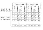
図1のフレーム構成は、例えば、PHSシステムで使用されるタイムスロットが4個(S1〜S4)の場合の構成であり、縦軸が周波数軸であり、横軸が時間軸である。図1において、ダウンリンク期間(基地局から端末への通信)及びアップリンク期間(端末から基地局への通信)は、共に周波数軸に対して、28個の周波数帯に分割されている。最初の周波数帯のサブチャネルは、コントロールサブチャネルと呼ばれ、制御チャネル(CCH)で使用している。このコントロールサブチャネルは、各周波数帯において、各タイムスロットのどのサブチャネルを使うかを指示する。
First, prior to the description of the embodiment of the present invention, the frame structure of OFDMA used in the communication system and communication method according to the embodiment of the present invention will be described with reference to FIG.
The frame configuration of FIG. 1 is, for example, a configuration in the case where there are four time slots (S1 to S4) used in the PHS system, the vertical axis is the frequency axis, and the horizontal axis is the time axis. In FIG. 1, the downlink period (communication from the base station to the terminal) and the uplink period (communication from the terminal to the base station) are both divided into 28 frequency bands with respect to the frequency axis. The subchannel of the first frequency band is called a control subchannel and is used in the control channel (CCH). This control subchannel indicates which subchannel of each time slot is used in each frequency band.
図1の例は、PHSシステムの例であり、コントロールサブチャネルC1〜C4で指定できる基地局は4つの基地局である。また、PHSシステムにおいては、100ms毎に制御チャネルを間歇送信する。 The example of FIG. 1 is an example of a PHS system, and the base stations that can be specified by the control subchannels C 1 to C 4 are four base stations. In the PHS system, the control channel is intermittently transmitted every 100 ms.
そして、残りの27の周波数帯には、データを送受信するトラフィックサブチャネルT1〜T108で構成されており、周波数方向に27個、時間軸方向に4個で、全部で108のサブチャネルで構成されている。
このトラフィックサブチャネルは、第1のサブチャネルであるアンカーサブチャネルと第2のサブチャネルであるエクストラサブチャネルとにより構成されている。
The remaining 27 frequency bands are composed of traffic sub-channels T 1 to T 108 for transmitting and receiving data. There are 27 sub-channels in the frequency direction and 4 in the time axis direction, for a total of 108 sub-channels. It is configured.
This traffic subchannel includes an anchor subchannel that is a first subchannel and an extra subchannel that is a second subchannel.
アンカーサブチャネル(第1のサブチャネル)とは、どのサブチャネルをどの端末が使用するかを各端末に通知するために使用したり、再送制御でデータが正しくやりとりできたかを基地局と端末でネゴシエーションするために使ったりするためのサブチャネルである。 The anchor subchannel (first subchannel) is used to notify each terminal which subchannel is used by each terminal, and whether the base station and the terminal can exchange data correctly by retransmission control. This is a subchannel for use in negotiation.
エクストラサブチャネル(第2のサブチャネル)とは、実際に使用するデータを送信するサブチャネルであり、1つの端末に対して、複数のエクストラサブチャネルを割り当てることができる。この場合、割り当てられたエクストラサブチャネルが多いほど帯域が広がるので高速な通信が可能となる。 The extra subchannel (second subchannel) is a subchannel that transmits data to be actually used, and a plurality of extra subchannels can be assigned to one terminal. In this case, as the number of allocated extra subchannels increases, the band is expanded, and high-speed communication is possible.
また、各端末が基地局との間の通信に対しどのサブチャネル割り当てるかを示すサブチャネルの割り当て情報をMAP情報と呼び、予め基地局から各端末へ通知される。 In addition, subchannel allocation information indicating which subchannel is allocated to each terminal for communication with the base station is called MAP information, and is notified from the base station to each terminal in advance.
以下、本発明に係る通信システムの実施の形態について、図面を参照して詳細に説明する。図2は、本実施の形態に係る通信システムにおいて端末と複数の基地局との間のハンドオーバの方法を示す模式図である。 DESCRIPTION OF EMBODIMENTS Hereinafter, embodiments of a communication system according to the present invention will be described in detail with reference to the drawings. FIG. 2 is a schematic diagram showing a handover method between a terminal and a plurality of base stations in the communication system according to the present embodiment.
図2において、端末20は、現在基地局10−1と通信中であり、スロットS2のアンカーサブチャネルを使って通信を行っている。この端末PSが基地局10−1との無線通信可能な範囲の境界に端末が移動した場合や、その他の原因により通信中の基地局10−1からの電波が弱くなり通信不可能となる場合や電波が弱くなるかまたは弱くなる前に、電波の強い別の基地局に切り替えを行うハンドオーバを行う必要がある。 In FIG. 2, the terminal 20 is currently communicating with the base station 10-1, and is communicating using the anchor subchannel of the slot S2. When the terminal PS moves to the boundary of a range where radio communication with the base station 10-1 is possible, or when radio waves from the base station 10-1 during communication weaken due to other causes, communication becomes impossible Before the radio wave becomes weaker or weakens, it is necessary to perform a handover for switching to another base station having a strong radio wave.
図2の場合、隣接の基地局10−2〜10−5が存在しているものとする。端末PSがパーチ状態となった場合、アンカーサブチャネルのみの接続となるので、アンカーサブチャネルで使用しているスロット以外の残り3スロットで制御チャネル(CCH)を受信可能である。例えば、図2においては、10−2、10−3、10−5はハンドオーバ(HO)可能であり、10−4はハンドオーバ(HO)不可である。 In the case of FIG. 2, it is assumed that adjacent base stations 10-2 to 10-5 exist. When the terminal PS enters the perch state, only the anchor subchannel is connected, so that the control channel (CCH) can be received in the remaining three slots other than the slot used in the anchor subchannel. For example, in FIG. 2, 10-2, 10-3, and 10-5 can be handed over (HO), and 10-4 cannot be handed over (HO).
次に、本発明の実施の形態に係る通信システム及び通信方法に用いられる端末及び基地局の構成を説明する。
図3は基地局の構成を示すブロック図、図4は端末の構成を示すブロック図である。
図3に示すように、基地局10は、アンテナに接続され後述する信号処理部12からの信号をRF信号に変換したり、逆に受信したRF信号を信号処理部12が扱えるように変換する無線通信部11、受信した信号または送信する信号を処理する信号処理部12、信号の変調または復調を行う変復調部13、上位通信網に接続される外部I/F部14、信号処理部12及び変復調部13を制御する制御部15によって構成されている。
Next, configurations of terminals and base stations used in the communication system and communication method according to the embodiment of the present invention will be described.
FIG. 3 is a block diagram showing the configuration of the base station, and FIG. 4 is a block diagram showing the configuration of the terminal.
As shown in FIG. 3, the
制御部15は、各端末毎に使用可能又は使用不可能なサブチャネルが示された情報を含み各端末に割り当てられたアンカーサブチャネル(ASCH)と、実際に使用するデータを含むエクストラサブチャネル(ESCH)と、を含むサブチャネルの端末毎の割り当てを設定するサブチャネル割当設定部15−1を有している。
サブチャネル割当設定部15−1は、端末からのアンカーサブチャネル(ASCH)切替要求を受信した場合、アンカーサブチャネル(ASCH)と同じスロットにエクストラサブチャネル(ESCH)を集めて割り当てる。
これにより、基地局10は、1つのスロットにアンカーサブチャネル(ASCH)とエクストラサブチャネル(ESCH)がまとまった状態となったサブチャネルの割り当て情報(MAP情報)を端末に送信する。
The
When receiving an anchor subchannel (ASCH) switching request from a terminal, the subchannel allocation setting unit 15-1 collects and allocates an extra subchannel (ESCH) to the same slot as the anchor subchannel (ASCH).
Thereby, the
図4に示すように、端末20は、アンテナに接続され後述する信号処理部22からの信号をRF信号に変換したり、逆に受信したRF信号を信号処理部22が扱えるように変換する無線通信部21、受信した信号または送信する信号を処理する信号処理部22、信号の変調または復調を行う変復調部23、データや音声等の入出力を行う入出力部24、信号処理部21及び無線通信部21を制御する制御部25によって構成されている。
As shown in FIG. 4, the terminal 20 is a radio that is connected to an antenna and converts a signal from a
制御部25は、ハンドオーバなどの際に、切替先となる基地局との通信状態(例えば、SINR、RSSIなど)を測定する通信状態測定部25−1、切替先となる基地局を検索するハンドオーバ先基地局検索部25−2を有している。
The
本実施の形態に係る通信システムにおけるハンドオーバのシーケンスについて説明する。まず、本実施の形態に係る通信システムにおける端末側から起動する場合のハンドオーバのシーケンスについて図5を参照して説明する。
・ダウンリンク(下り回線)の無線品質が劣化した場合、例えば、SINR(Signal-to-Interference and Noise Ratio:信号対干渉雑音比)が基準となる閾値以下となった場合、ハンドオーバ動作を開始する。
なお、この無線品質劣化の判断は、10dBμV程度を閾値として、受信信号の強度(RSSI:Received Signal Strength Indicator)などによるものであっても良い。
・端末20は切替元の10−1へアンカーサブチャネル(ASCH)切替要求を送信する。
・切替元の基地局10−1はサブチャネル割当部15−1の制御により、アンカーサブチャネル(ASCH)と同じスロットにエクストラサブチャネル(ESCH)を集めて割り当てる。このようにして、1つのスロットにアンカーサブチャネル(ASCH)とエクストラサブチャネル(ESCH)がまとまった状態のサブチャネル割り当て情報(MAP情報)を端末に送信する。
・端末20は、通信が行われていないすべての相対スロット(アンカーサブチャネル(ASCH)、エクストラサブチャネル(ESCH)の割り当てが全くないスロット)において、周辺基地局の検索を行う。
・端末20は、検索により見つかった切替先の基地局10−n(10−1以外の基地局)に対し、リンクチャネル(LCH)確立要求を送信する。
・切替先の基地局10−nは、リンクチャネル(LCH)確立要求を受信したら、アンカーサブチャネル(ASCH)を選択し、端末に対してリンクチャネル(LCH)割当を送信する。
・端末20と切替先の基地局10−nは、切替先の基地局10−nのアンカーサブチャネル(ASCH)により通信を開始する。この切替先の基地局10−nのアンカーサブチャネル(ASCH)による通信はダウンリンク、アップリンクのいずれを先に行っても良い。
・切替先の基地局10−nのアンカーサブチャネル(ASCH)でエクストラサブチャネル(ESCH)を割り当てるMAP情報を受信したとき、端末20はハンドオーバが成功したと見なし、切替元の基地局10−1とのリンクを切断する。
A handover sequence in the communication system according to the present embodiment will be described. First, a handover sequence when starting from the terminal side in the communication system according to the present embodiment will be described with reference to FIG.
・ When the radio quality of the downlink (downlink) deteriorates, for example, when the SINR (Signal-to-Interference and Noise Ratio) falls below a reference threshold value, the handover operation is started. .
The determination of the radio quality degradation may be based on received signal strength (RSSI: Received Signal Strength Indicator) with a threshold of about 10 dBμV.
The terminal 20 transmits an anchor subchannel (ASCH) switching request to the switching source 10-1.
The switching source base station 10-1 collects and allocates the extra subchannel (ESCH) to the same slot as the anchor subchannel (ASCH) under the control of the subchannel allocation unit 15-1. In this way, the subchannel allocation information (MAP information) in which the anchor subchannel (ASCH) and the extra subchannel (ESCH) are collected in one slot is transmitted to the terminal.
The terminal 20 searches for neighboring base stations in all the relative slots in which communication is not performed (slots in which no anchor subchannel (ASCH) or extra subchannel (ESCH) is allocated).
The terminal 20 transmits a link channel (LCH) establishment request to the switching destination base station 10-n (base station other than 10-1) found by the search.
When the switching destination base station 10-n receives the link channel (LCH) establishment request, it selects the anchor subchannel (ASCH) and transmits link channel (LCH) assignment to the terminal.
The terminal 20 and the switching destination base station 10-n start communication using the anchor subchannel (ASCH) of the switching destination base station 10-n. The communication by the anchor subchannel (ASCH) of the switching destination base station 10-n may be performed in either the downlink or the uplink first.
When receiving the MAP information for allocating the extra subchannel (ESCH) on the anchor subchannel (ASCH) of the switching destination base station 10-n, the terminal 20 considers that the handover has succeeded, and switches to the switching source base station 10-1. And break the link.
また、本実施の形態に係る通信システムにおける基地局側から起動する場合のハンドオーバのシーケンスについて図6を参照して説明する。
・アップリンク(上り回線)の無線品質が劣化した場合、例えば、SINR(Signal-to-Interference and Noise Ratio:信号対干渉雑音比)が基準となる閾値以下となった場合、ハンドオーバ動作を開始する。
なお、この無線品質劣化の判断は、10dBμV程度を閾値として、受信信号の強度(RSSI:Received Signal Strength Indicator)などによるものであっても良い。
・切替元の基地局10−1はハンドオーバ指示を端末20に送信する。
・この指示を受信して、端末は切替元の基地局へアンカーサブチャネル(ASCH)切替要求を送信する。
・切替元の基地局10−1は、サブチャネル割当部15−1の制御により、アンカーサブチャネル(ASCH)と同じスロットにエクストラサブチャネル(ESCH)を集めて割り当てる。このようにして、1つのスロットにアンカーサブチャネル(ASCH)とエクストラサブチャネル(ESCH)がまとまった状態のサブチャネル割り当て情報(MAP情報)を端末に送信する。
・端末20は、通信が行われていないすべての相対スロット(アンカーサブチャネル(ASCH)、エクストラサブチャネル(ESCH)の割り当てが全くないスロット)において、周辺基地局の検索を行う。
・端末20は、検索により見つかった切替先の基地局10−n(10−1以外の基地局)に対し、リンクチャネル(LCH)確立要求を送信する。
・切替先の基地局10−nは、リンクチャネル(LCH)確立要求を受信したら、アンカーサブチャネル(ASCH)を選択し、端末に対してリンクチャネル(LCH)割当を送信する。
・端末20と切替先の基地局10−nは、切替先の基地局10−nのアンカーサブチャネル(ASCH)により通信を開始する。この切替先の基地局10−nのアンカーサブチャネル(ASCH)による通信はダウンリンク、アップリンクのいずれを先に行っても良い。
・切替先の基地局10−nのアンカーサブチャネル(ASCH)でエクストラサブチャネル(ESCH)を割り当てるMAP情報を受信したとき、端末20はハンドオーバが成功したと見なし、切替元の基地局10−1とのリンクを切断する。
In addition, a handover sequence when starting from the base station side in the communication system according to the present embodiment will be described with reference to FIG.
-When the uplink (uplink) radio quality deteriorates, for example, when the SINR (Signal-to-Interference and Noise Ratio) falls below the reference threshold, the handover operation is started. .
The determination of the radio quality degradation may be based on received signal strength (RSSI: Received Signal Strength Indicator) with a threshold of about 10 dBμV.
The switching source base station 10-1 transmits a handover instruction to the terminal 20.
Upon receiving this instruction, the terminal transmits an anchor subchannel (ASCH) switching request to the switching source base station.
The switching source base station 10-1 collects and allocates the extra subchannel (ESCH) to the same slot as the anchor subchannel (ASCH) under the control of the subchannel allocation unit 15-1. In this way, the subchannel allocation information (MAP information) in which the anchor subchannel (ASCH) and the extra subchannel (ESCH) are collected in one slot is transmitted to the terminal.
The terminal 20 searches for neighboring base stations in all the relative slots in which communication is not performed (slots in which no anchor subchannel (ASCH) or extra subchannel (ESCH) is allocated).
The terminal 20 transmits a link channel (LCH) establishment request to the switching destination base station 10-n (base station other than 10-1) found by the search.
When the switching destination base station 10-n receives the link channel (LCH) establishment request, it selects the anchor subchannel (ASCH) and transmits link channel (LCH) assignment to the terminal.
The terminal 20 and the switching destination base station 10-n start communication using the anchor subchannel (ASCH) of the switching destination base station 10-n. The communication by the anchor subchannel (ASCH) of the switching destination base station 10-n may be performed in either the downlink or the uplink first.
When receiving the MAP information for allocating the extra subchannel (ESCH) on the anchor subchannel (ASCH) of the switching destination base station 10-n, the terminal 20 considers that the handover has succeeded, and switches to the switching source base station 10-1. And break the link.
なお、上述の端末側から起動する場合のハンドオーバのシーケンス又は基地局側から起動する場合のハンドオーバのシーケンスにおいて、基地局が端末からアンカーサブチャネルの切替要求を受信した場合、少なくとも1つのスロットは基地局が使用する制御チャネルを空けるようにしても良い。 In the handover sequence when starting from the terminal side or the handover sequence when starting from the base station side, when the base station receives an anchor subchannel switching request from the terminal, at least one slot is You may make it free the control channel which a station uses.
なお、端末は、1つのスロットにアンカーサブチャネル(ASCH)とエクストラサブチャネル(ESCH)がまとまった状態のMAP情報を受信したとき、端末側から見て、無線品質が前記の閾値以下に劣化していなかった場合には、ハンドオーバ先の基地局の検索処理のみを行うようにしても良い。 In addition, when the terminal receives MAP information in which an anchor subchannel (ASCH) and an extra subchannel (ESCH) are collected in one slot, the radio quality deteriorates below the threshold value as viewed from the terminal side. If not, only the search process of the handover destination base station may be performed.
10、10−1、10−2、10−3、10−4、10−5、10−n 基地局
11 無線通信部
12 信号処理部
13 変復調部
14 外部I/F部
15 制御部
15−1 サブチャネル割当設定部(サブチャネル割当設定手段)
20 端末
21 無線通信部
22 信号処理部
23 変復調部
24 入出力部
25 制御部
25−1 通信状態測定部(通信状態測定手段)
25−2 ハンドオーバ先基地局検索部(ハンドオーバ先基地局検索手段)
10, 10-1, 10-2, 10-3, 10-4, 10-5, 10-
20 terminal 21
25-2 Handover Destination Base Station Search Unit (Handover Destination Base Station Search Means)
Claims (5)
各基地局は、各端末毎に使用可能又は使用不可能なサブチャネルが示された情報を含み各端末に割り当てられた第1のサブチャネルと、実際に使用するデータを含む第2のサブチャネルと、を含むサブチャネルの端末毎の割り当てを設定するサブチャネル割当設定手段を有し、
前記複数の端末のうちの一つの端末から前記第1のサブチャネルの切替要求を受信した場合、当該端末に割り当てられた前記第1のサブチャネルと同じスロットに前記第2のサブチャネルを集めて割り当てることを特徴とする通信システム。 In an OFDMA communication system that performs data communication between a plurality of base stations and a plurality of terminals,
Each base station includes a first subchannel allocated to each terminal including information indicating usable or unusable subchannels for each terminal, and a second subchannel including data actually used And subchannel allocation setting means for setting allocation for each terminal of subchannels including:
When the first subchannel switching request is received from one of the plurality of terminals, the second subchannel is collected in the same slot as the first subchannel allocated to the terminal. A communication system characterized by assigning.
前記複数の端末のうちの一つの端末から前記第1のサブチャネルの切替要求を受信した場合、前記第1のサブチャネルと同じスロットに前記第2のサブチャネルを集めて割り当てたサブチャネルの割り当て情報を当該端末に送信することを特徴とする基地局。Allocation of subchannels when the second subchannel is collected and allocated in the same slot as the first subchannel when a switching request for the first subchannel is received from one of the plurality of terminals A base station that transmits information to the terminal.
切替先となる基地局との通信状態を測定する通信状態測定部と、前記切替先となる基地局を検索する切替先基地局検索部と、を有していることを特徴とする端末。A terminal comprising: a communication state measurement unit that measures a communication state with a base station that is a switching destination; and a switching destination base station search unit that searches for the base station that is the switching destination.
ダウンリンクの無線品質が劣化した場合、前記端末が切替元の基地局へ前記第1のサブチャネル切替要求を送信するステップと、When the downlink radio quality is degraded, the terminal transmits the first subchannel switching request to the switching source base station;
前記切替元の基地局が、前記第1のサブチャネルと同じスロットに前記第2のサブチャネルを集めて割り当て、1つのスロットに前記第1のサブチャネルと前記第2のサブチャネルがまとまった状態のサブチャネル割り当て情報を端末に送信するステップと、The switching source base station collects and assigns the second subchannel to the same slot as the first subchannel, and the first subchannel and the second subchannel are collected in one slot. Transmitting the subchannel allocation information to the terminal,
前記端末が、前記サブチャネル割り当て情報を受信して、通信が行われていないすべての相対スロットにおいて、周辺基地局の検索を行うステップと、The terminal receives the subchannel allocation information and performs a search for neighboring base stations in all relative slots in which communication is not performed;
前記端末と、検索により見つかった切替先の基地局とのリンクを確立し、前記切替元の基地局とのリンクを切断するステップと、を含むことを特徴とする基地局切替方法。Establishing a link between the terminal and a switching destination base station found by the search and disconnecting the link with the switching source base station.
アップリンクの無線品質が劣化した場合、切替元の基地局がハンドオーバ指示を端末に送信するステップと、When uplink radio quality is degraded, the switching source base station transmits a handover instruction to the terminal; and
前記ハンドオーバ指示を受信して、前記端末が前記切替元の基地局へ前記第1のサブチャネル切替要求を送信するステップと、Receiving the handover instruction, and the terminal transmitting the first subchannel switching request to the switching source base station;
前記切替元の基地局が、前記第1のサブチャネルと同じスロットに前記第2のサブチャネルを集めて割り当て、1つのスロットに前記第1のサブチャネルと前記第2のサブチャネルがまとまった状態のサブチャネル割り当て情報を前記端末に送信するステップと、The switching source base station collects and assigns the second subchannel to the same slot as the first subchannel, and the first subchannel and the second subchannel are collected in one slot. Transmitting the subchannel allocation information to the terminal;
前記端末が、前記サブチャネル割り当て情報を受信して、通信が行われていないすべての相対スロットにおいて、周辺基地局の検索を行うステップと、 The terminal receives the subchannel allocation information and performs a search for neighboring base stations in all relative slots in which communication is not performed;
前記端末と、検索により見つかった切替先の基地局とのリンクを確立し、前記切替元の基地局とのリンクを切断するステップと、を含むことを特徴とする基地局切替方法。Establishing a link between the terminal and a switching destination base station found by the search and disconnecting the link with the switching source base station.
Priority Applications (3)
| Application Number | Priority Date | Filing Date | Title |
|---|---|---|---|
| JP2006293242A JP4926647B2 (en) | 2006-10-27 | 2006-10-27 | Communication system, base station and terminal used in the communication system, and base station switching method |
| PCT/JP2007/070856 WO2008053788A1 (en) | 2006-10-27 | 2007-10-25 | Communication system and base stations, terminals and base station switching method used in that communication system |
| US12/447,425 US8493930B2 (en) | 2006-10-27 | 2007-10-25 | Communication system, base station and mobile station used in the communication system, and base station switching method |
Applications Claiming Priority (1)
| Application Number | Priority Date | Filing Date | Title |
|---|---|---|---|
| JP2006293242A JP4926647B2 (en) | 2006-10-27 | 2006-10-27 | Communication system, base station and terminal used in the communication system, and base station switching method |
Publications (3)
| Publication Number | Publication Date |
|---|---|
| JP2008113090A JP2008113090A (en) | 2008-05-15 |
| JP2008113090A5 JP2008113090A5 (en) | 2010-10-28 |
| JP4926647B2 true JP4926647B2 (en) | 2012-05-09 |
Family
ID=39445391
Family Applications (1)
| Application Number | Title | Priority Date | Filing Date |
|---|---|---|---|
| JP2006293242A Expired - Fee Related JP4926647B2 (en) | 2006-10-27 | 2006-10-27 | Communication system, base station and terminal used in the communication system, and base station switching method |
Country Status (1)
| Country | Link |
|---|---|
| JP (1) | JP4926647B2 (en) |
Families Citing this family (6)
| Publication number | Priority date | Publication date | Assignee | Title |
|---|---|---|---|---|
| JP4654267B2 (en) * | 2008-05-27 | 2011-03-16 | 京セラ株式会社 | Base station and radio communication method |
| US8199633B2 (en) | 2008-05-27 | 2012-06-12 | Kyocera Corporation | Base station and wireless communication method |
| US8676208B2 (en) | 2008-06-11 | 2014-03-18 | Mediatek Inc. | Scanning and handover operation in multi-carrier wireless communications systems |
| JP5420373B2 (en) * | 2009-11-04 | 2014-02-19 | 京セラ株式会社 | Mobile communication system, mobile station, base station, and handover method |
| JP5384297B2 (en) * | 2009-11-04 | 2014-01-08 | 京セラ株式会社 | Mobile communication system, mobile station, base station, and handover method |
| JP2011109679A (en) * | 2010-12-15 | 2011-06-02 | Kyocera Corp | Base station and wireless communication method |
Family Cites Families (3)
| Publication number | Priority date | Publication date | Assignee | Title |
|---|---|---|---|---|
| JP3403950B2 (en) * | 1998-09-07 | 2003-05-06 | 松下電器産業株式会社 | Mobile station apparatus, broadcast channel receiving method in mobile station apparatus, and cell search method in mobile station apparatus |
| US7573851B2 (en) * | 2004-12-07 | 2009-08-11 | Adaptix, Inc. | Method and system for switching antenna and channel assignments in broadband wireless networks |
| US9184870B2 (en) * | 2005-04-01 | 2015-11-10 | Qualcomm Incorporated | Systems and methods for control channel signaling |
-
2006
- 2006-10-27 JP JP2006293242A patent/JP4926647B2/en not_active Expired - Fee Related
Also Published As
| Publication number | Publication date |
|---|---|
| JP2008113090A (en) | 2008-05-15 |
Similar Documents
| Publication | Publication Date | Title |
|---|---|---|
| JP5620528B2 (en) | COMMUNICATION SYSTEM, BASE STATION DEVICE, AND MOBILE STATION DEVICE | |
| US5956642A (en) | Adaptive channel allocation method and apparatus for multi-slot, multi-carrier communication system | |
| CA2562513C (en) | Handling communication interferences in wireless systems | |
| US8493930B2 (en) | Communication system, base station and mobile station used in the communication system, and base station switching method | |
| EP1931089B1 (en) | Radio communication apparatus and radio communication method | |
| JP5156334B2 (en) | Wireless communication apparatus and wireless communication method | |
| JP4583388B2 (en) | Base station equipment | |
| KR20050091591A (en) | System and method for operation band adaptive modulation and coding subchannel in a orthogonal frequency division multiple access system | |
| WO2007144947A1 (en) | Radio communication system | |
| KR20060044335A (en) | System and method for operation safety channel in a orthogonal frequency division multiple access system | |
| US8582537B2 (en) | Communication method and terminal apparatus using the same | |
| US8699427B2 (en) | OFDMA communication system and communication method | |
| JP4926647B2 (en) | Communication system, base station and terminal used in the communication system, and base station switching method | |
| US8675574B2 (en) | OFDMA communication system and communication method | |
| JP4818413B2 (en) | COMMUNICATION SYSTEM, ITS BASE STATION, AND COMMUNICATION METHOD | |
| JP4403515B2 (en) | COMMUNICATION SYSTEM, ITS BASE STATION, AND COMMUNICATION METHOD | |
| JP4818208B2 (en) | Communication system, base station, and communication method | |
| JP2008113089A (en) | Communication system, and base station, terminal, and base station switching method used for same system | |
| KR101139048B1 (en) | Communication system, its base station, and communication method | |
| JP4384655B2 (en) | Communication system, base station, and communication method | |
| US8520614B2 (en) | Communication method, base station apparatus, and terminal apparatus using the communication method | |
| JP2008301308A (en) | Allocation method and base station apparatus using the same | |
| JP2011010352A (en) | User equipment | |
| JP2010022057A (en) | Communication system and communication method using ofdma method |
Legal Events
| Date | Code | Title | Description |
|---|---|---|---|
| RD04 | Notification of resignation of power of attorney |
Free format text: JAPANESE INTERMEDIATE CODE: A7424 Effective date: 20080331 |
|
| A521 | Request for written amendment filed |
Free format text: JAPANESE INTERMEDIATE CODE: A523 Effective date: 20080515 |
|
| A621 | Written request for application examination |
Free format text: JAPANESE INTERMEDIATE CODE: A621 Effective date: 20090928 |
|
| A521 | Request for written amendment filed |
Free format text: JAPANESE INTERMEDIATE CODE: A523 Effective date: 20100913 |
|
| A131 | Notification of reasons for refusal |
Free format text: JAPANESE INTERMEDIATE CODE: A131 Effective date: 20111108 |
|
| A521 | Request for written amendment filed |
Free format text: JAPANESE INTERMEDIATE CODE: A523 Effective date: 20111227 |
|
| TRDD | Decision of grant or rejection written | ||
| A01 | Written decision to grant a patent or to grant a registration (utility model) |
Free format text: JAPANESE INTERMEDIATE CODE: A01 Effective date: 20120207 |
|
| A01 | Written decision to grant a patent or to grant a registration (utility model) |
Free format text: JAPANESE INTERMEDIATE CODE: A01 |
|
| A61 | First payment of annual fees (during grant procedure) |
Free format text: JAPANESE INTERMEDIATE CODE: A61 Effective date: 20120208 |
|
| FPAY | Renewal fee payment (event date is renewal date of database) |
Free format text: PAYMENT UNTIL: 20150217 Year of fee payment: 3 |
|
| R150 | Certificate of patent or registration of utility model |
Ref document number: 4926647 Country of ref document: JP Free format text: JAPANESE INTERMEDIATE CODE: R150 Free format text: JAPANESE INTERMEDIATE CODE: R150 |
|
| LAPS | Cancellation because of no payment of annual fees |