JP4921134B2 - Air conditioner - Google Patents
Air conditioner Download PDFInfo
- Publication number
- JP4921134B2 JP4921134B2 JP2006325223A JP2006325223A JP4921134B2 JP 4921134 B2 JP4921134 B2 JP 4921134B2 JP 2006325223 A JP2006325223 A JP 2006325223A JP 2006325223 A JP2006325223 A JP 2006325223A JP 4921134 B2 JP4921134 B2 JP 4921134B2
- Authority
- JP
- Japan
- Prior art keywords
- drain pan
- guider
- heat exchanger
- air
- blower
- Prior art date
- Legal status (The legal status is an assumption and is not a legal conclusion. Google has not performed a legal analysis and makes no representation as to the accuracy of the status listed.)
- Expired - Fee Related
Links
Images


Description
本発明は、空気調和機に関し、特に逆V字型の熱交換器を備えた分離型の空気調和機の室内ユニットに関するものである。 The present invention relates to an air conditioner, and more particularly to an indoor unit of a separation type air conditioner provided with an inverted V-shaped heat exchanger.
特許文献1には、室内ユニットに逆V字型の熱交換器を備え、後板(キャビネット)、送風機支持部、前ドレンパン、後ドレンパンを全て同時に一体成形し、送風機やノーズなどの送風系に対する組立て精度を向上させると共に熱膨張などによる騒音(ピシ音)を抑えることができる空気調和機の室内ユニットが提案されている。
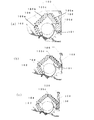
ここで、図6(a)(b)(c)に従来の空気調和機の室内ユニットを示す。通常、空気調和機の室内ユニットは、製品の格差付けのため冷暖房能力の異なる複数の機種を企画することが多く、外形寸法が異なる2〜3種類の筐体に対して、形状の異なる複数の熱交換器を組合せて複数の機種を企画することになる。 Here, the indoor unit of the conventional air conditioner is shown to Fig.6 (a) (b) (c). Usually, indoor units of air conditioners often plan a plurality of models with different cooling and heating capabilities for product disparity, and a plurality of different shapes are used for two to three types of casings having different outer dimensions. Multiple models will be planned by combining heat exchangers.
図6(a)は、筐体の一部を構成する後板100(キャビネット)に後ドレンパン101、前ドレンパン102およびリアガイダ103を一体で形成し、送風機104を囲むように4つの熱交換器105a〜105dを逆V字形に配置し、さらに、その後ろ側に別の補助熱交換器105eを配置した例を示す。
FIG. 6A shows that a rear drain pan 101, a
図6(b)は、送風機104を囲むように3つの熱交換器105a〜105cを配置した例を示す。この例では、後板100と一体となった後ドレンパン101の形成位置が同図(a)と異なっている。
FIG. 6B shows an example in which three heat exchangers 105 a to 105 c are arranged so as to surround the
さらに、図6(c)は、図6(b)と同様に、送風機103を囲むように、3つの熱交換器105a〜105cを配置した例を示す。この例では、後ろ側の熱交換器105cを支持するために、熱交換器105aと後ドレンパン101との間にスペーサ106を挿入している。
Furthermore, FIG.6 (c) shows the example which has arrange | positioned three heat exchangers 105a-105c so that the air blower 103 may be enclosed similarly to FIG.6 (b). In this example, a
一般に、空気調和機において、形状の異なる複数の熱交換器を組合せて複数の機種を企画する場合、特許文献1の室内ユニットでは、機種に応じて複数のキャビネット(後板)の金型を製作する必要がある。例えば、図6(a)(b)に示す室内ユニットでは、同図(a)に示す熱交換器105cと同図(b)に示す熱交換器105dとでは、後ろ側の熱交換器の形状が異なる。そのため、後ドレンパンの位置やリアガイダの形状が異なることになり、製品の外形寸法が同じであっても、後板(キャビネット)は異なった形状にする必要がある。
Generally, in air conditioners, when planning multiple models by combining multiple heat exchangers with different shapes, the indoor unit of
このため、例えば、外形寸法が異なる2種類の製品に3種類の熱交換器を組み合わせて6種類の機種を企画する場合、6種類の後板(キャビネット)の金型を製作する必要が生じていた。 For this reason, for example, when planning 6 types of models by combining 3 types of heat exchangers with 2 types of products with different external dimensions, it is necessary to manufacture 6 types of back plate (cabinet) molds. It was.
また、その改善策として、図6(c)に示すように、スペーサ106を取付けて後板100および後ドレンパン101を共通使用し、後板(キャビネット)100の金型費用を抑える方策も考えられる。しかし、送風機104の背面側にはリアガイダ103が後板100(キャビネット)と一体に設けられており、風量特性や騒音を最適にするため、リアガイダ103の形状も種々工夫するのが通常であるため、同じ後板105に異なる熱交換器を取り付ける場合、熱交換器の形状に応じてリアガイダ103の形状を調整することができなくなる。
Further, as an improvement measure, as shown in FIG. 6C, a measure to suppress the mold cost of the rear plate (cabinet) 100 by attaching the
また、特許文献1のような後板(キャビネット)では、その金型は、複数の部品を一体で形成しているので、大型で複雑な金型構造となり、その製作期間が長くなるとともに、また複雑なスライド構造などを多く含むため、金型の動作不良などのトラブルを生じやすく、さらには金型費用も非常に高価なものとなっていた。
Moreover, in the back plate (cabinet) like
本発明は、上記に鑑み、最小限の数の後板で複数の製品のラインナップを可能とし、風量特性に優れた空気調和機の提供を目的とする。 In view of the above, an object of the present invention is to provide an air conditioner that enables a lineup of a plurality of products with a minimum number of rear plates and is excellent in air flow characteristics.
上記目的を達成するため、本発明は、室内ユニットの筐体が前面パネルと後板で構成され、該筐体に空気の吸込口と吹出口とが形成され、前記筐体内に、空気を送風する送風機と、該送風機を囲むように配された熱交換器と、後ろ側の熱交換器の結露水を受ける第1の後ドレンパンと、吹出口に至る空気通路を形成するために送風機に近接して配置されたスタビライザ及びリアガイダとを備えた空気調和機において、前記第1の後ドレンパンと前記後板とが一体的に形成され、前記後ろ側の熱交換器の下端位置が前記第1の後ドレンパンよりも離れた位置にあるときに、前記第1の後ドレンパンとは別体であって、且つ、前記後ろ側の熱交換器の結露水を受けるための第2のドレンパンが、前記第1の後ドレンパンの上側に連結可能とされることにより、前記第1の後ドレンパンと前記後板とを共通使用することができることを特徴とする。
In order to achieve the above object, according to the present invention, a housing of an indoor unit is constituted by a front panel and a rear plate, an air suction port and an air outlet are formed in the housing, and air is blown into the housing. Close to the blower to form a blower, a heat exchanger arranged to surround the blower, a first rear drain pan that receives the dew condensation water of the rear heat exchanger, and an air passage leading to the outlet in the air conditioner having a stabilizer and rear guider disposed in the first drain pan after and said rear plate are formed integrally with the lower end position of the heat exchanger of the rear side is the first when located away than the rear drain pan, wherein the first after drain pan be separate, and a second drain pan for receiving dew condensation water of the heat exchanger of the rear side, the first Ru is a connectable to the upper pan after 1 And by, characterized in that can be commonly used and the back plate and the first rear drain pan.
上記構成によると、第1の後ドレンパンを一体的に形成した後板に熱交換器を設置するとき、後ろ側の熱交換器の形状により、その下端位置が第1の後ドレンパンよりも離れた位置にあるときに、その後ろ側の熱交換器の結露水を受けるための第2のドレンパンを第1の後ドレンパンの上側に連結するので、機種が異なっても共通の後板(キャビネット)を使用することができる。 According to the above configuration, when the heat exchanger is installed on the rear plate integrally formed with the first rear drain pan, the lower end position thereof is separated from the first rear drain pan due to the shape of the rear heat exchanger. Since the second drain pan for receiving condensed water from the heat exchanger behind it is connected to the upper side of the first rear drain pan when in position, a common rear plate (cabinet) can be used regardless of the model. Can be used.
また、前記リアガイダは、吹出口側の第1のリアガイダと、機種に応じて前記第1のリアガイダの空気通路上流側に連接する第2のリアガイダとを備え、前記第2のリアガイダが、前記第2の後ドレンパンと一体に形成され、前記第2の後ドレンパンが前記第1の後ドレンパンの上部を覆うように、前記第1の後ドレンパンに載置されるようにしてもよい。上記構成によると、機種に応じて第1のリアガイダに第2のリアガイダを接続するだけで、最適な風量特性や騒音対策にもなる。また、熱交換器の形状に合わせて第2の後ドレンパンを設置することができる。さらに、機種に応じてドレンパンの位置を変更し、かつ最適な風量特性が得られる。
The rear guider includes a first rear guider on the outlet side and a second rear guider connected to the upstream side of the air passage of the first rear guider depending on the model, and the second rear guider includes the first rear guider. it is formed in the drain pan integrally after 2, wherein as the second rear drain pan covers the upper portion of the drain pan after the first, may be placed on the drain pan after the first. According to the above configuration, only by connecting the second rear guider to the first rear guider according to the model, it is possible to obtain optimum air flow characteristics and noise countermeasures. Moreover , a 2nd back drain pan can be installed according to the shape of a heat exchanger. Furthermore, the position of the drain pan is changed according to the model, and an optimum air flow characteristic can be obtained.
前記リアガイダは、吹出口側の第1のリアガイダと、機種に応じて前記第1のリアガイダの空気通路上流側に連接する第2のリアガイダとを備え、前記第1のリアガイダが前記第1の後ドレンパンと一体に形成されるようにしてもよい。
The rear guider includes a first rear guider of the air outlet side, and a second rear guider articulating the air passage upstream of the first rear guider according to the model, after the first rear guider is the first It may be formed integrally with the drain pan .
上記構成によると、後板に第1のリアガイダと第1の後ドレンパンとを一体に形成する
ので、部品点数が少なくなる。
According to the above configuration, because it forms a first rear guider and the drain pan after the first to the rear plate together, the number of components is that a little.
第2のリアガイダを、第1のリアガイダおよび第1の後ドレンパンと別体で形成することもできる。これにより、機種に応じて第1のリアガイダに第2のリアガイダを接続するだけで、最適な風量特性や騒音対策にもなる。 The second rear guider may be formed separately from the first rear guider and the first rear drain pan. Thus, only by connecting the second rear guider to the first rear guider according to the model, an optimum air flow characteristic and noise countermeasure can be obtained.
また、前ドレンパンと第1の後ドレンパンとを一体で形成することで、部品点数を少なくして組立て工数を低減することができる。 Further, by integrally forming the front drain pan and the first rear drain pan, the number of parts can be reduced and the assembly man-hour can be reduced.
さらに、第1の後ドレンパンに貯留した結露水を前ドレンパンに導く流水路が後板に形成される。この流水路により、第1の後ドレンパンから前ドレンパンに結露水を流し、前ドレンパンからまとめて外部に排出することができる。 Further, a flow channel for guiding the condensed water stored in the first rear drain pan to the front drain pan is formed on the rear plate. With this flow channel, the dew condensation water can flow from the first rear drain pan to the front drain pan and can be discharged from the front drain pan to the outside.
また、第2の後ドレンパンに、第1の後ドレンパンへ結露水を導く排水口を形成し、第2のドレンパンに溜まった結露水を排水口を通じて第1のドレンパンに流すことができる。 In addition, a drain outlet that guides condensed water to the first rear drain pan can be formed in the second rear drain pan, and the condensed water accumulated in the second drain pan can be flowed to the first drain pan through the drain outlet.
以上のとおり、本発明によれば、同じ後板(キャビネット)で異なる熱交換器を組合せた複数の機種を展開しても、それぞれの機種で最適な風量特性に得るとともに、発生するトータルの金型費用を最小限に抑えることが可能となる。 As described above, according to the present invention, even when a plurality of models in which different heat exchangers are combined on the same rear plate (cabinet), an optimum air flow characteristic is obtained in each model, and the total amount of generated gold is increased. Mold costs can be minimized.
本発明の実施形態を図1〜図5に示す。図1は空気調和機の室内ユニットの斜視図、同じく室内ユニットの側面断面図、図3はキャビネット(後板)と後ドレンパンの斜視図である。図4および図5は室内ユニットの筐体の側面断面図である。 An embodiment of the present invention is shown in FIGS. FIG. 1 is a perspective view of an indoor unit of an air conditioner, a side sectional view of the indoor unit, and FIG. 3 is a perspective view of a cabinet (rear plate) and a rear drain pan. 4 and 5 are side sectional views of the housing of the indoor unit.
室内ユニット1は、図2に示すように、箱状の筐体2の上面に空気の吸込口3が形成され、前面下部に吹出口4が形成される。筐体2の内部には、吸込口3から吹出口4に至る内部空気通路に熱交換器5と送風機6とが配設される。
As shown in FIG. 2, the
筐体2は、前側に室内ユニットの主要部材である熱交換器5や送風機6を保持し、背面側で室内の壁面に取り付けられる板状の後板2aと、背面が開放し後板2aに嵌合される箱状の前面パネル2bとから構成される。
The
前面パネル2bには、その上面に吸込口3が形成され、前面下部に吹出口4が形成される。吹出口4には、縦ルーバ及び横ルーバからなる風向変更装置12と、その前側に第1の軸10周りに開閉回動自在に軸支された導風パネル7とが設けられる。
The
導風パネル7は、その開放姿勢で略水平方向に位置し、吹出口4から吹出す空気を略水平ないし斜め上方に飛ばすことができるようになっている。また、導風パネル7は、カバーパネル8と延長パネル9とに分割され、カバーパネル8が延長パネル9に対して第2の軸11周りに開閉回動自在に軸支される。そして、カバーパネル8の開姿勢で吹出口4からの風を垂直下方に導くことができるようになっている。
The
熱交換器5は、送風機6を三方から囲むように逆V字形に配置される。熱交換器5は、機種に応じて複数の熱交換器が配置される。図4の例では、3つの熱交換器5a〜5cが前後および上側の三方から送風機6を囲むように逆V字形に配置され、さらに、後側の熱交換器5cの背面側には、一つの補助熱交換器5dが後ろ側熱交換器5cと平行に配置された形態となっている。
The
一方、図5に示す熱交換器50では、4つの熱交換器50a〜50dが送風機6を囲むように配置され、その背面側にさらに補助熱交換器50eが配置される。したがって、図4に示す熱交換器5と図5に示す熱交換器50とでは、後ろ側の熱交換器の高さ位置が異なる。図4に示す後ろ側の熱交換器5cの下端部は、図5に示す後ろ側の熱交換器50dに比べて、上方位置にある。そのため、図5に示す後ドレンパン18をそのまま使用することはできない。この場合の対策は後述する。
On the other hand, in the
各熱交換器5は、熱媒管と多数のフィンとから直方体形状に形成され、熱媒管の端部同士で他の熱交換器と接続され、冷凍サイクルの一部を構成するようになっている。
Each
また、図2および図4において、後ろ側の熱交換器5c、5dと前側の熱交換器5a、5bとの間に切換弁(不図示)を設け、除湿運転時には、後ろ側の熱交換器5c、5bを凝縮器として使用し、前側の熱交換器5a,5bで湿気を除去した空気を、後ろ側熱交換器5c、5dの排熱を利用して暖めて吹出口4から放出する再熱除湿もできるようになっている。
2 and 4, a switching valve (not shown) is provided between the rear heat exchangers 5c and 5d and the front heat exchangers 5a and 5b, and the rear heat exchanger is used during the dehumidifying operation. 5c, 5b is used as a condenser, and the air from which moisture has been removed by the front heat exchangers 5a, 5b is warmed using the exhaust heat of the rear heat exchangers 5c, 5d and discharged from the
また、前側の熱交換器5aの下方には、熱交換器5aからの結露水を貯留する前ドレンパン17が設けられる。また、後ろ側の熱交換器5cの下方には、熱交換器5cからの結露水を貯留する第1の後ドレンパン18が設けられる。そして、前ドレンパン17および第1の後ドレンパン18は、その両端部の支持板24によって一体的に形成される。
Further, a
前ドレンパン17および第1の後ドレンパン18は、樋状に形成された公知構造のもので、その後端部が後板2aの下端部と接合し、後板2aと一体で形成される。ただ、後ドレンパン18の内部には、後述する第2の後ドレンパン19の裏面リブ25を支持する受け部28が形成される。
The
また、前ドレンパン17の下面には送風機6に接近してスタビライザ15が一体形成される。第1の後ドレンパン18の前側には送風機6に接近してリアガイダ16が形成される。そして、スタビライザ15およびリアガイダ16に挟まれて内部空気通路が形成される。
Further, a
送風機6は、クロスフローファンであって、その回転軸の軸方向が左右方向とされる。送風機6は、内部空気通路において熱交換器5よりも吹出口4側に配置される。
The
リアガイダ16は、吹出口側の第1のリアガイダ16aと、機種に応じて第1のリアガイダ16aの空気通路上流側に連接する第2のリアガイダ(舌部)16bとから構成される。リアガイダ16は、内部空気通路の送風方向に合わせて円弧状に形成される。
The
また、第1のリアガイダ16aは、第1の後ドレンパン18と一体に形成される。つまり、後板2aと、第1の後ドレンパン18および第1のリアガイダ16a、さらには前ドレンパン17およびスタビライザ15が一体的に成形される。
The first rear guider 16 a is formed integrally with the first
第1のリアガイダ16aの上端には、段差状の係合受け部29が形成され、第2のリアガイダ(舌部)16bの下端部30を係合載置することができるようになっている。 A step-shaped engagement receiving portion 29 is formed at the upper end of the first rear guider 16a so that the lower end portion 30 of the second rear guider (tongue portion) 16b can be engaged and placed thereon.
さらに、第1の後ドレンパン18の端部には排水口21が形成される。第1の後ドレンパン18は、図3で長手方向に排水口21に向かって傾斜しており、この排水口21から前ドレンパン17に連通する流水路20が支持板24、つまり後板2aと一体的に形成されている。この流水路20は、第1の後ドレンパン18に貯留した結露水を前ドレンパン17に導く。
Further, a
一方、機種に応じて取り付けられる第2のリアガイダ(舌部)16bや第2の後ドレンパン19が設けられる。図4では、第2のリアガイダ(舌部)16bと第2の後ドレンパン19とが一体化されたものを例示する。これの例では、第2の後ドレンパン19の裏面に左右方向に間隔をおいて複数のリブ25が形成されている。リブ25の下端には係合凹部が形成され、この係合凹部が第1の後ドレンパン18の内部に形成された突起28と係合して、第1の後ドレンパン18の上側に第2の後ドレンパン19が載置される。
On the other hand, a second rear guider (tongue) 16b and a second
なお、第2の後ドレンパン19は、図3で長手方向に排水部22に向かって傾斜しており、第2の後ドレンパン19の結露水は排水部22より第1の後ドレンパン18または流水路20を経由して前ドレンパン17に導かれる。
Note that the second
また、図5の例では、第2の後ドレンパン19は必要ないが、第2のリアガイダ(舌部)16bのみを製造し、第2のリアガイダ(舌部)16bの下端部30を第1のリアガイダ16aの上端係合受け部29に係合載置している。
In the example of FIG. 5, the second
なお、支持板24には、送風機6を回転駆動するモータ(不図示)を支持する支持部も一体に形成してもよい。
The
また、図2に示すように、筐体2の吸込口3には吸込んだ空気から塵埃を除去するフィルタ26が配置される。また、フィルタ26に付着した塵埃をフィルタ26を移動させながら、ブラシと吸引手段により除去するフィルタ清掃装置27が設けられている。
As shown in FIG. 2, a
上記構成において、形状の異なる熱交換器を同じ形状の後板2aに取り付ける例を図4及び図5に示す。図4は、3つの熱交換器5a〜5cが前後および上側の三方から送風機6を囲むように逆V字形に配置された例である。一方、図5は4つの熱交換器50a〜50dが送風機6を囲むように配置された例である。両者において、後ろ側の熱交換器5cと50dとでは、図4の熱交換器の方が短い寸法に設定されている。したがって、図4の機種では、第2のリアガイダ(舌部)16bおよび第2の後ドレンパン19の一体成形品を第1の後ドレンパン18の上側に取り付ける。
4 and 5 show an example in which heat exchangers having different shapes are attached to the
一方、図5に示す室内ユニット1では、後ろ側の熱交換器50dの下端位置が下側であるため、第1の後ドレンパン18上に熱交換器50dを取り付ける。そして、別成形した第2のリアガイダ(舌部)16bを第1のリアガイダ16aに取り付ける。
On the other hand, in the
このように、第2のリアガイダ(舌部)16bや第2の後ドレンパン19を異ならせるだけで、後板2aを共通使用することができる。しかも、第2のリアガイダ(舌部)16bは、熱交換器の形状に応じた個別の形状に調整可能であり、それぞれの機種で最適な風量特性を得ることができる。さらに、図6(c)に示すスペーサ106も使用する必要がない。
As described above, the
また、第2のリアガイダ(舌部)16bや後ドレンパン19は、後板2aに比べるとかなり小さな金型で済むため、金型の製作期間も短く、金型費用も安価に抑えることができる。例えば、製品の外形寸法が2種類で熱交換器3種類を組合せて合計6種類の機種を企画する場合、従来では6種類の後板の金型が必要であったが、本発明では、製品の外形寸法に応じて2種類の後板(キャビネット)の金型と後ドレンパンまたはリアガイダの金型を追加するだけで済む。さらに、機種個別に熱交換器の形状に応じてリアガイダの形状を調整できるため、機種ごとに最適な風量特性を得ることができる。
Further, since the second rear guider (tongue) 16b and the
さらに、後板2aには、第1の後ドレンパン18の結露水を前ドレンパン17へ導く流水路20が一体に形成されているので、第1の後ドレンパン18から流水路20を通して前ドレンパン17に結露水を流すことができ、これらの結露水をまとめて外部に放出することができる。
Further, since the
また、第2の後ドレンパン19には第1の後ドレンパン18へ結露水を導く排水口22が形成されているので、第2の後ドレンパン19の結露水はその排水口22を通して下方の第1の後ドレンパン18へ流れ込み、さらに第1のドレンパン18の排水口21から流水路20を通じて前ドレンパン17へ流れ込み、室外へ排水処理される。
Further, since the second
また、後板2aには第1の後ドレンパン18を一体に設けず、第2の後ドレンパンと第2のリアガイダ(舌部)16bを一体にして、熱交換器ごとに対応する形状にすることもできる。この場合、第1の後ドレンパン18を後板2aに設けないので、後板2aの金型構造がより簡略化でき、さらに、熱交換器に応じた最適な風量特性を得ることができる。
Also, the first
このように、熱交換器5,50や後板2aの組合せが異なる複数の機種においても、後ドレンパン18又は19で発生した結露水は、水はねなどすることなく、確実に前ドレンパン17を通じて室外へ排水処理することができる。
As described above, even in a plurality of models having different combinations of the
なお、本発明は、上記実施形態に限定されるものではなく、本発明の範囲内で多くの修正変更を加えることができるのは勿論である。 In addition, this invention is not limited to the said embodiment, Of course, many correction changes can be added within the scope of the present invention.
1 室内ユニット
2 筐体
2a 後板(キャビネット)
2b 前面パネル
3 吸込口
4 吹出口
5 熱交換器
6 送風機
7 導風パネル
8 カバーパネル
9 延長パネル
10 第1の軸
11 第2の軸
15 スタビライザ
16 リアガイダ
16a 第1のリアガイダ
16b 第2のリアガイダ(舌部)
17 前ドレンパン
18 第1の後ドレンパン
19 第2の後ドレンパン
20 流水路
24 支持板
26 フィルタ
27 フィルタ清掃装置
50a〜50d 熱交換器
1
2b
17
Claims (3)
前記第1の後ドレンパンと前記後板とが一体的に形成され、前記後ろ側の熱交換器の下端位置が前記第1の後ドレンパンよりも離れた位置にあるときに、前記第1の後ドレンパンとは別体であって、且つ、前記後ろ側の熱交換器の結露水を受けるための第2の後ドレンパンが、前記第1の後ドレンパンの上側に連結可能とされることにより、前記第1の後ドレンパンと前記後板とを共通使用することができることを特徴とする空気調和機。 The housing of the indoor unit is composed of a front panel and a rear plate, and an air suction port and an air outlet are formed in the housing, and a blower that blows air is disposed in the housing so as to surround the blower. A heat exchanger, a first rear drain pan that receives the dew condensation water of the rear heat exchanger, and a stabilizer and a rear guider that are arranged close to the blower to form an air passage leading to the air outlet. In the air conditioner
The first drain pan after and said rear plate are formed integrally, when the lower end position of the heat exchanger of the rear side is in a position away than drain pan after the first, after the first the drain pan be separate, and, second rear drain pan for receiving dew condensation water of the heat exchanger of the rear side, by Rukoto is capable connected to the upper side of the first rear drain pan, wherein An air conditioner characterized in that the first rear drain pan and the rear plate can be used in common .
Priority Applications (1)
| Application Number | Priority Date | Filing Date | Title |
|---|---|---|---|
| JP2006325223A JP4921134B2 (en) | 2006-12-01 | 2006-12-01 | Air conditioner |
Applications Claiming Priority (1)
| Application Number | Priority Date | Filing Date | Title |
|---|---|---|---|
| JP2006325223A JP4921134B2 (en) | 2006-12-01 | 2006-12-01 | Air conditioner |
Publications (3)
| Publication Number | Publication Date |
|---|---|
| JP2008138929A JP2008138929A (en) | 2008-06-19 |
| JP2008138929A5 JP2008138929A5 (en) | 2009-05-14 |
| JP4921134B2 true JP4921134B2 (en) | 2012-04-25 |
Family
ID=39600585
Family Applications (1)
| Application Number | Title | Priority Date | Filing Date |
|---|---|---|---|
| JP2006325223A Expired - Fee Related JP4921134B2 (en) | 2006-12-01 | 2006-12-01 | Air conditioner |
Country Status (1)
| Country | Link |
|---|---|
| JP (1) | JP4921134B2 (en) |
Families Citing this family (2)
| Publication number | Priority date | Publication date | Assignee | Title |
|---|---|---|---|---|
| CN103452907B (en) * | 2012-06-04 | 2015-09-16 | 珠海格力电器股份有限公司 | Indoor apparatus of air conditioner |
| JP6324255B2 (en) * | 2014-08-05 | 2018-05-16 | 三菱電機株式会社 | Air conditioner |
Family Cites Families (1)
| Publication number | Priority date | Publication date | Assignee | Title |
|---|---|---|---|---|
| DD228069A1 (en) * | 1984-11-01 | 1985-10-02 | Zeiss Jena Veb Carl | ARRANGEMENT FOR OPTICAL RADIATION IN PHOTOMETRIC ANALYSIS METERING DEVICES |
-
2006
- 2006-12-01 JP JP2006325223A patent/JP4921134B2/en not_active Expired - Fee Related
Also Published As
| Publication number | Publication date |
|---|---|
| JP2008138929A (en) | 2008-06-19 |
Similar Documents
| Publication | Publication Date | Title |
|---|---|---|
| KR101517346B1 (en) | Ceiling type air conditioner | |
| JP5823881B2 (en) | Air conditioner | |
| JP6048818B2 (en) | Outdoor unit | |
| JP5496697B2 (en) | Air conditioner outdoor unit | |
| JP4187034B2 (en) | Indoor unit of air conditioner | |
| JP4921134B2 (en) | Air conditioner | |
| JP5401355B2 (en) | Air conditioner indoor unit | |
| JP5447567B2 (en) | Air conditioning indoor unit | |
| CN1877207B (en) | Air adjusting device | |
| JP2009198012A (en) | Indoor unit of air conditioner | |
| JP6349550B2 (en) | Dehumidifier | |
| JP5668739B2 (en) | Air conditioning indoor unit | |
| JP5305782B2 (en) | Air conditioner | |
| JP2008267656A (en) | Air conditioner | |
| JP2006214603A (en) | Air conditioner | |
| JP2006090694A (en) | Air conditioner | |
| JP4495369B2 (en) | Air conditioner | |
| JP4857794B2 (en) | Air conditioner indoor unit | |
| KR20070060876A (en) | Air conditioner | |
| JP2007045326A (en) | Air conditioner | |
| KR100780792B1 (en) | Air conditioner | |
| JP4592368B2 (en) | Air conditioner | |
| JP2010048470A (en) | Air conditioner | |
| JP6115855B2 (en) | Outdoor unit | |
| JP5167088B2 (en) | Air conditioner |
Legal Events
| Date | Code | Title | Description |
|---|---|---|---|
| A521 | Written amendment |
Free format text: JAPANESE INTERMEDIATE CODE: A523 Effective date: 20090327 |
|
| A621 | Written request for application examination |
Free format text: JAPANESE INTERMEDIATE CODE: A621 Effective date: 20090327 |
|
| A977 | Report on retrieval |
Free format text: JAPANESE INTERMEDIATE CODE: A971007 Effective date: 20110425 |
|
| A131 | Notification of reasons for refusal |
Free format text: JAPANESE INTERMEDIATE CODE: A131 Effective date: 20110517 |
|
| A521 | Written amendment |
Free format text: JAPANESE INTERMEDIATE CODE: A523 Effective date: 20110705 |
|
| TRDD | Decision of grant or rejection written | ||
| A01 | Written decision to grant a patent or to grant a registration (utility model) |
Free format text: JAPANESE INTERMEDIATE CODE: A01 Effective date: 20120110 |
|
| A01 | Written decision to grant a patent or to grant a registration (utility model) |
Free format text: JAPANESE INTERMEDIATE CODE: A01 |
|
| A61 | First payment of annual fees (during grant procedure) |
Free format text: JAPANESE INTERMEDIATE CODE: A61 Effective date: 20120202 |
|
| R150 | Certificate of patent or registration of utility model |
Ref document number: 4921134 Country of ref document: JP Free format text: JAPANESE INTERMEDIATE CODE: R150 Free format text: JAPANESE INTERMEDIATE CODE: R150 |
|
| FPAY | Renewal fee payment (event date is renewal date of database) |
Free format text: PAYMENT UNTIL: 20150210 Year of fee payment: 3 |
|
| LAPS | Cancellation because of no payment of annual fees |