JP4920516B2 - Telephone system and proxy answering phone - Google Patents
Telephone system and proxy answering phone Download PDFInfo
- Publication number
- JP4920516B2 JP4920516B2 JP2007180897A JP2007180897A JP4920516B2 JP 4920516 B2 JP4920516 B2 JP 4920516B2 JP 2007180897 A JP2007180897 A JP 2007180897A JP 2007180897 A JP2007180897 A JP 2007180897A JP 4920516 B2 JP4920516 B2 JP 4920516B2
- Authority
- JP
- Japan
- Prior art keywords
- telephone
- proxy
- header
- call
- message
- Prior art date
- Legal status (The legal status is an assumption and is not a legal conclusion. Google has not performed a legal analysis and makes no representation as to the accuracy of the status listed.)
- Active
Links
Images


Classifications
-
- H—ELECTRICITY
- H04—ELECTRIC COMMUNICATION TECHNIQUE
- H04M—TELEPHONIC COMMUNICATION
- H04M3/00—Automatic or semi-automatic exchanges
- H04M3/42—Systems providing special services or facilities to subscribers
- H04M3/54—Arrangements for diverting calls for one subscriber to another predetermined subscriber
-
- H—ELECTRICITY
- H04—ELECTRIC COMMUNICATION TECHNIQUE
- H04M—TELEPHONIC COMMUNICATION
- H04M1/00—Substation equipment, e.g. for use by subscribers
- H04M1/253—Telephone sets using digital voice transmission
- H04M1/2535—Telephone sets using digital voice transmission adapted for voice communication over an Internet Protocol [IP] network
-
- H—ELECTRICITY
- H04—ELECTRIC COMMUNICATION TECHNIQUE
- H04M—TELEPHONIC COMMUNICATION
- H04M19/00—Current supply arrangements for telephone systems
- H04M19/02—Current supply arrangements for telephone systems providing ringing current or supervisory tones, e.g. dialling tone or busy tone
- H04M19/04—Current supply arrangements for telephone systems providing ringing current or supervisory tones, e.g. dialling tone or busy tone the ringing-current being generated at the substations
- H04M19/041—Encoding the ringing signal, i.e. providing distinctive or selective ringing capability
-
- H—ELECTRICITY
- H04—ELECTRIC COMMUNICATION TECHNIQUE
- H04M—TELEPHONIC COMMUNICATION
- H04M3/00—Automatic or semi-automatic exchanges
- H04M3/02—Calling substations, e.g. by ringing
-
- H—ELECTRICITY
- H04—ELECTRIC COMMUNICATION TECHNIQUE
- H04M—TELEPHONIC COMMUNICATION
- H04M3/00—Automatic or semi-automatic exchanges
- H04M3/42—Systems providing special services or facilities to subscribers
- H04M3/42365—Presence services providing information on the willingness to communicate or the ability to communicate in terms of media capability or network connectivity
- H04M3/42374—Presence services providing information on the willingness to communicate or the ability to communicate in terms of media capability or network connectivity where the information is provided to a monitoring entity such as a potential calling party or a call processing server
-
- H—ELECTRICITY
- H04—ELECTRIC COMMUNICATION TECHNIQUE
- H04M—TELEPHONIC COMMUNICATION
- H04M7/00—Arrangements for interconnection between switching centres
- H04M7/006—Networks other than PSTN/ISDN providing telephone service, e.g. Voice over Internet Protocol (VoIP), including next generation networks with a packet-switched transport layer
-
- H—ELECTRICITY
- H04—ELECTRIC COMMUNICATION TECHNIQUE
- H04M—TELEPHONIC COMMUNICATION
- H04M1/00—Substation equipment, e.g. for use by subscribers
- H04M1/64—Automatic arrangements for answering calls; Automatic arrangements for recording messages for absent subscribers; Arrangements for recording conversations
- H04M1/642—Automatic arrangements for answering calls; Automatic arrangements for recording messages for absent subscribers; Arrangements for recording conversations storing speech in digital form
-
- H—ELECTRICITY
- H04—ELECTRIC COMMUNICATION TECHNIQUE
- H04M—TELEPHONIC COMMUNICATION
- H04M1/00—Substation equipment, e.g. for use by subscribers
- H04M1/64—Automatic arrangements for answering calls; Automatic arrangements for recording messages for absent subscribers; Arrangements for recording conversations
- H04M1/65—Recording arrangements for recording a message from the calling party
- H04M1/6505—Recording arrangements for recording a message from the calling party storing speech in digital form
-
- H—ELECTRICITY
- H04—ELECTRIC COMMUNICATION TECHNIQUE
- H04M—TELEPHONIC COMMUNICATION
- H04M7/00—Arrangements for interconnection between switching centres
- H04M7/0024—Services and arrangements where telephone services are combined with data services
- H04M7/0033—Notification or handling of incoming calls by a computer
-
- H—ELECTRICITY
- H04—ELECTRIC COMMUNICATION TECHNIQUE
- H04M—TELEPHONIC COMMUNICATION
- H04M7/00—Arrangements for interconnection between switching centres
- H04M7/12—Arrangements for interconnection between switching centres for working between exchanges having different types of switching equipment, e.g. power-driven and step by step or decimal and non-decimal
- H04M7/1205—Arrangements for interconnection between switching centres for working between exchanges having different types of switching equipment, e.g. power-driven and step by step or decimal and non-decimal where the types of switching equipement comprises PSTN/ISDN equipment and switching equipment of networks other than PSTN/ISDN, e.g. Internet Protocol networks
- H04M7/129—Details of providing call progress tones or announcements
Landscapes
- Engineering & Computer Science (AREA)
- Signal Processing (AREA)
- Computer Networks & Wireless Communication (AREA)
- Telephonic Communication Services (AREA)
- Telephone Function (AREA)
Description
本発明は、インターネットプロトコル(IP)に基づいて動作する電話システム、サーバおよび代理応答電話機に係り、特に、ソフトフォン利用が多いIP電話環境に対する利便性の高い電話システム、サーバおよび代理応答電話機に関する。 The present invention relates to a telephone system, a server, and a proxy answering telephone that operate based on the Internet Protocol (IP), and more particularly to a telephone system, a server, and a proxy answering telephone that are highly convenient for an IP telephone environment in which softphones are frequently used.
近年、IP電話が急速に普及している。また、それに伴い付帯する様々なサービスを提供するシステムや仕組みが発明されている。その中に着信側が不在の時にメッセージを自動的に録音する機能を提供する留守録システムがある。 In recent years, IP telephones are rapidly spreading. Further, a system and a mechanism for providing various services accompanying it have been invented. Among them, there is an answering machine system that provides a function of automatically recording a message when the called party is absent.
留守録システムの基本的な構成と仕組みについて、特許文献1に従来技術として記載された図2を参照して説明する。この図において、集中制御装置は、いわゆる電話交換機の役割を果たし電話端末同士の呼制御を行う。通信ネットワークの端末Aから発信者aが送信先端末Bを呼出す場合、端末Aは、(1)端末B呼出信号を発信し集中制御装置の交換機または呼制御サーバにアクセスし、(2)集中制御装置は、端末Bを検出・接続して端末B呼出信号を送信、(3)端末Bが呼出信号に一定時間応答しない場合、前記集中制御装置は端末B無応答を確認し、前記集中制御装置は、(4)端末B無応答に呼応して集中的にボイス情報を記憶するボイスメールサーバに端末Aを接続、(5)端末Aとボイスメールサーバとの間を通信可能に通信ルートを設定、(6)端末Aの発信者aからのボイス情報は、ボイスメールサーバに送信・記録され、(7)中央制御装置は端末Bにボイス情報が記録された事を通知し(8)ボイスメールサーバに前記ボイス情報記録済の端末B表示を受信者は確認すると、端末Bから前記集中制御装置に接続しボイスメールサーバを呼出して記録されたボイス情報を要求し、(9)端末B宛のボイス情報が検出されて、(10)ボイス情報は、前記集中制御装置を介し端末Bに送信・再生されて受信者はボイス情報を確認する。 A basic configuration and mechanism of an answering machine system will be described with reference to FIG. In this figure, the centralized control device plays the role of a so-called telephone exchange and performs call control between telephone terminals. When the caller a calls the destination terminal B from the terminal A of the communication network, the terminal A (1) issues a terminal B call signal and accesses the exchange or call control server of the centralized control device, and (2) centralized control. The apparatus detects and connects terminal B and transmits a terminal B call signal. (3) When terminal B does not respond to the call signal for a certain period of time, the central control apparatus confirms that terminal B does not respond, and the central control apparatus (4) Terminal A is connected to a voice mail server that centrally stores voice information in response to no response from terminal B, and (5) a communication route is set to enable communication between terminal A and the voice mail server. (6) Voice information from caller a of terminal A is transmitted / recorded to a voice mail server, (7) The central controller notifies terminal B that the voice information has been recorded (8) Voice mail The voice information storage When the receiver confirms the terminal B display, the terminal B connects to the centralized control device and calls the voice mail server to request the recorded voice information. (9) Voice information addressed to the terminal B is detected. (10) The voice information is transmitted / reproduced to the terminal B via the central control apparatus, and the receiver confirms the voice information.
なお、ここではボイスメールサーバとして説明しているが同様の機能を提供するものに留守録サーバあり、ほぼ同じ手法のシステムである。
以上のような一般的なボイスメールサーバシステムにおいて一辺倒な留守録処理だけでなく、より利便性を高めたものに、特許文献2に記載の手法がある。この手法は、前述の説明でのボイスメールサーバにあたるWebサーバにおいて、サーバ利用者が細かい設定を登録することにより、ユーザが不在の場合に電話を取る前に発信者の伝言メッセージを録音することなどが出来る。
Although the voice mail server is described here, there is an answering machine that provides a similar function, which is a system of almost the same method.
In the general voice mail server system as described above, there is a technique described in Patent Document 2 that is not only a troublesome recording process but also more convenient. In this method, in the Web server corresponding to the voice mail server described above, the server user registers a detailed setting, so that when the user is absent, the caller's message message is recorded before taking a call. I can do it.
一方で、特許文献3のように、IPアドレスに基づいて管理されるIP電話端末に内蔵されるRAM部のボイスメール記録領域に、発信者のボイスデータ(メッセージ情報)を記録し保存することにより、利便性を改善するボイスメールシステムが知られている。つまり、発信者からのメッセージ情報を、集中的にメッセージ情報を記憶するサーバ側ではなく、電話端末側に保存させる手法である。 On the other hand, by recording and storing the voice data (message information) of the caller in the voice mail recording area of the RAM unit built in the IP telephone terminal managed based on the IP address as in Patent Document 3. Voice mail systems that improve convenience are known. That is, this is a technique for storing message information from the caller on the telephone terminal side, not on the server side that stores message information in a concentrated manner.
また一方で、ネットワークシステムの進化やIP電話に代表されるコミュニケーション機器の進化により、企業のワークスタイルにも変革がおきている。従業員に固定の席を用意せず、従業員は毎日違う机で仕事が行えるフリーアドレス制と言われるワークスタイルである。フリーアドレスによれば、従業員は、その日の気分や、業務プロジェクトに応じて自由に席を変更するといった、レイアウトフリーなオフィススタイルが可能となる。フリーアドレスでは、パーソナルコンピュータ(以下、PCと略す)にインストールして利用するソフトフォンが利用される。PCとソフトフォンを使うためのハンドセットとネットワークに接続できる環境さえあれば、どこの席であってもパソコンを繋いだ場所が自席環境となるからであり、ソフトフォンであれば固定電話機の位置による束縛を解消することができる。フリーアドレス制が導入された先進的なオフィスでは、従業員全員にノート型PCとソフトフォンが支給され、オフィス内には各グループの机の島に補助的に固定電話機が1〜数台設置することが一般的である。 On the other hand, corporate work styles are changing due to the evolution of network systems and communication devices such as IP phones. The work style is said to be a free address system where employees do not have fixed seats and employees can work at different desks every day. According to the free address, employees can have a layout-free office style that allows them to freely change their seats according to their mood and business project. The free address uses a softphone that is installed and used in a personal computer (hereinafter abbreviated as PC). If there is an environment that can be connected to a handset and a network for using a PC and softphone, the place where the PC is connected becomes the seating environment regardless of the seat, and if it is a softphone, it depends on the location of the fixed phone The binding can be removed. In advanced offices with a free address system, all employees are provided with laptops and softphones, and one or more fixed phones are installed on the desk island of each group in the office. It is common.
特許文献4には、呼制御情報にある何れかの識別情報を判定して、判定結果に応じて着信パターンを変える発明が記載されている。
特許文献5には、アナログのPBXに接続するタイプのセンタ収容方留守録装置が記載されている。
特許文献6および特許文献7には、1台の電話機に複数の電話番号を設け、番号ごとに異なる着信音を設ける発明が記載されている。
特許文献8には、着呼を受けて該当者のスケジュールをスケジュール管理部に確認し、その情報に基づいて、着信、留守録または転送する判定動作をする発明が記載されている。
Patent Document 4 describes an invention in which any identification information in call control information is determined and the incoming pattern is changed according to the determination result.
Patent Document 6 and
Patent Document 8 describes an invention in which an incoming call is received, the schedule of the corresponding person is confirmed with the schedule management unit, and based on the information, an incoming call operation, a recorded message, or a transfer operation is performed.
ソフトフォン利用環境での留守録システムの動作について、図1を参照して説明する。ここで、図1はソフトフォン利用者が不在のときの電話システムの動作を説明するブロック図である。図1は、受信者bが利用するIP電話はソフトフォンで、受信者bが不在のために端末Bは起動していない状態を表している。この状態で端末Aから端末Bへの発呼を説明すると以下の通りとなる。まず(1)端末Aは、端末B呼出信号をテレフォニーサーバへ発信する。(2)テレフォニーサーバは、端末Bに接続するためのIPアドレスを自信に格納されるテーブルから解決しようとする。しかし、(3)テレフォニーサーバは、端末Bが起動していないため接続先のIPアドレスが解決できない。そこで、(4)テレフォニーサーバは、端末Bの不在転送先として登録されている宛先を確認し、(5)端末Aとの呼接続を設定し、(6)留守録サーバとの呼接続を設定する。(7)留守録サーバは、メッセージ情報を保存する。 The operation of the answering system in the softphone usage environment will be described with reference to FIG. Here, FIG. 1 is a block diagram for explaining the operation of the telephone system when the softphone user is absent. FIG. 1 shows a state in which the IP phone used by the recipient b is a soft phone and the terminal B is not activated due to the absence of the recipient b. In this state, a call from the terminal A to the terminal B will be described as follows. First, (1) terminal A transmits a terminal B call signal to the telephony server. (2) The telephony server tries to resolve the IP address for connecting to the terminal B from the table stored with confidence. However, (3) the telephony server cannot resolve the connection destination IP address because the terminal B is not activated. Therefore, (4) the telephony server confirms the destination registered as the absent transfer destination of terminal B, (5) sets up call connection with terminal A, and (6) sets up call connection with answering machine. To do. (7) The message recording server stores message information.
ソフトフォン利用者の多い職場環境で留守録システムの利用を考えた場合、留守録サーバの導入による不在時の転送処理では、起動していないソフトフォン宛にかけられた電話は不在転送先に指定された留守録サーバへ転送されることになる。ソフトフォン利用者が緊急な都合で出社が1時間遅れる事になった場合、特許文献1の図2の環境であったならば、端末Bが鳴動するので、職場に連絡してその旨を伝えておけば、その人の電話端末宛に電話が掛かってきた場合、状況に応じて代理応答を行い都合で1時間遅れてくる旨の伝言を職場の者が代理で伝えられる。しかし、ソフトフォン利用者の職場で、留守録サーバを導入してしまうと、着信できない通話は無条件に留守録サーバへ転送されることになる。この結果、不在者宛てに電話があったことすら、職場の他の人には判別できなくなってしまう。 When considering using an answering machine in a work environment where there are many softphone users, a call made to a softphone that has not been activated is designated as an absent forwarding destination in the forwarding process when there is no answering machine installed. Will be forwarded to the answering machine. If a softphone user is delayed for 1 hour due to urgent circumstances, if the environment shown in FIG. 2 of Patent Document 1 is used, terminal B will ring. Then, when a call is made to the person's telephone terminal, a substitute response is made according to the situation and a message to the effect that the work is delayed for one hour is sent on behalf of the person in the workplace. However, if an answering machine is installed at the work site of a softphone user, a call that cannot be received is unconditionally transferred to the answering machine. As a result, even if there is a call to the absentee, it cannot be determined by other people in the workplace.
この様な問題に対処するには、ソフトフォンが起動していない場合は、一端職場にある別の電話機に転送して、一定時間応答がない場合に、さらに留守録サーバへ転送して留守録処理を行わせるという手法が考えられる。この様な運用では、職場単位での電話の取りこぼし問題には効果的だが、留守録サーバを設置することによる無駄な電話の取り次ぎや代理応答を減らしたいという本来の目的からはずれてしまう。また電話を掛けている方は、その間呼出し待ち時間が長くなってしまう問題もある。 In order to deal with such problems, if the softphone is not activated, it will be transferred to another phone at the office, and if there is no response for a certain period of time, it will be further transferred to the answering server and recorded. A method of performing processing is conceivable. This kind of operation is effective for the problem of call drop at the workplace, but it deviates from the original purpose of reducing unnecessary call relays and proxy responses by setting up an answering machine. In addition, there is a problem that the call waiting time becomes longer for those who are making calls.
また、前述の様な場合に、ソフトフォン利用者が一時的に留守録サーバへ転送するか職場の別の電話機に転送するのかをテレフォニーサーバ宛へ設定変更して対応する手法も考えられる。しかし、いちいち手動による設定変更をしなくてはならず、柔軟性に欠け、設定変更の戻し忘れなどの新たな課題も発生する。 Also, in the case described above, a method can be considered in which the softphone user changes the setting to the telephony server to temporarily transfer to the answering machine or to another telephone in the workplace. However, manual setting changes must be made one by one, resulting in lack of flexibility and new problems such as forgetting to return setting changes.
特許文献2に記載の手法では、ソフトフォンが多数を占めるような環境は想定されておらず、着呼先の電話機が起動していない場合については考えられていない。
特許文献3に記載の電話端末にボイスメールデータを保存しておく方式での対応を考えた場合、まず根本的な課題として、ソフトフォンでは端末の電源が入っていなければそもそもメッセージを受けることが出来ない。また、不在転送先として職場の補助的に設置されている固定電話を指定し、その固定電話に特許文献3に記載の手法を採用すれば、確かにメッセージ情報を保存することが可能となる。しかし、このときソフトフォンと固定電話機が1対1で対応していないので、複数の電話端末に対するメッセージ情報が1台の固定電話に保存されることになり、誰宛のメッセージかが判らない。
In the method described in Patent Document 2, the environment, such as softphone majority is not assumed, not considered for the case where an incoming call destination phone is not activated.
When considering the use of the method of storing voice mail data in the telephone terminal described in Patent Document 3, as a fundamental problem, a soft phone may receive a message in the first place if the terminal is not turned on. I can't. In addition, if a fixed telephone set in the workplace is specified as the absence transfer destination and the method described in Patent Document 3 is adopted for the fixed telephone, the message information can be surely stored. However, since the softphone and the fixed telephone do not correspond one-to-one at this time, message information for a plurality of telephone terminals is stored in one fixed telephone, and it is not known who the message is addressed to.
更に、大規模IP電話システムにおいて代理応答/留守録機能を提供するには、規模に見合ったサーバの構築や設置などが必要なため経済的なハードルが高い。オフィスのフロアやグループ単位での簡易的な代理応答機能の提供が望まれている。 Furthermore, providing a proxy response / answering function in a large-scale IP telephone system requires construction and installation of a server corresponding to the scale, which is an economic hurdle. It is desired to provide a simple proxy response function for each office floor or group.
本発明の課題は、このような問題点を解決し、ソフトフォン利用者やフリーアドレス制の職場でも適切に代理応答サービスが提供でき、かつ利用者の状況に応じた柔軟性の高い代理応答機能の実現方法およびそのシステムを提供することである。 The problem of the present invention is to solve such problems and provide a proxy response service appropriately for softphone users and workplaces with free addresses, and a highly flexible proxy response function according to the user's situation The realization method and its system are provided.
上述した課題は、IP電話機と、IP代理応答電話機と、IP電話機とIP代理応答電話機との発着信を制御するサーバとからなり、サーバは、IP電話機宛ての着呼があったとき、IP電話機の状態を判定し、IP電話機が着呼できないと判定したとき、IP電話機の識別子を付与してIP代理応答電話機に着呼を転送する電話システムにより、解決できる。 The above-described problem includes an IP telephone, an IP proxy answering telephone, and a server that controls outgoing / incoming calls of the IP telephone and the IP proxy answering telephone. When the server receives an incoming call addressed to the IP telephone, the IP telephone When the IP telephone determines that the IP telephone cannot be called, the telephone system that assigns the IP telephone identifier and transfers the incoming call to the IP proxy answering telephone can solve the problem.
また、IP電話機とIP代理応答電話機と接続され、IP電話機とIP代理応答電話機との発着信を制御し、IP電話機宛ての着呼があったとき、IP電話機の状態を判定し、IP電話機が着呼できないと判定したとき、IP電話機の識別子を付与してIP代理応答電話機に着呼を転送するサーバにより、解決できる。 In addition, the IP telephone and the IP proxy response telephone are connected to control the outgoing and incoming calls of the IP telephone and the IP proxy response telephone. When an incoming call is made to the IP telephone, the state of the IP telephone is determined. When it is determined that the incoming call cannot be made, it can be solved by a server that assigns the identifier of the IP telephone and transfers the incoming call to the IP proxy response telephone.
さらに、ネットワークを介して、IP電話機とテレフォニーサーバと接続され、テレフォニーサーバからINVITEメッセージを受信したとき、INVITEメッセージを解析して、転送された着呼かIP代理応答電話機宛ての着呼かを判定し、判定結果に基づいて鳴動音を出力するIP代理応答電話機により、解決できる。 Furthermore, when an IP phone and a telephony server are connected via a network and an INVITE message is received from the telephony server, the INVITE message is analyzed to determine whether the incoming call is a forwarded call or an IP proxy answering telephone. However, this can be solved by an IP proxy response telephone that outputs a ringing tone based on the determination result.
本発明によれば、ソフトフォンが起動していない番号宛に電話が発信され予めテレフォニーサーバに登録されている不在転送先に着信転送されたとき、電話機の着信パターンによって、電話機の利用者が転送か否か判別ができる。 According to the present invention, when a call is made to a number for which the softphone is not activated and the call is transferred to a call forwarding destination registered in advance in the telephony server, the telephone user transfers the call according to the incoming call pattern of the telephone. It can be determined whether or not.
以下、この発明の実施の形態について、実施例を用い図面を参照しながら説明する。なお、実質同一部位には同じ参照番号を振り、説明は繰り返さない。 Hereinafter, embodiments of the present invention will be described with reference to the drawings using examples. The same reference numerals are assigned to substantially the same parts, and the description will not be repeated.
図2は、留守録システムが適用されたネットワークを示すブロック図である。図2において、IP電話端末などがLAN(Local Area Network)17、WAN(Wide Area Network)18などのIPネットワークを介して接続されている。IP電話端末にはさまざまなタイプがあり、LANに直接接続できる固定型IP電話機(図示せず)や、PC13、14上にソフトフォンと呼ばれる電話アプリケーションプログラム15(以下、ソフトフォンと記す)にスピーカ・マイクがついたハンドセット16を接続したIP電話端末や、留守録サービスを提供する固定IP電話機型の留守録電話機10などがある。テレフォニーサーバ11は、IP電話システム内のIP電話端末(留守録電話機10、PC13、14)を管理し、これら電話端末間の通話のための呼制御を行うものである。IP電話システム構築時には、すべてのIP電話端末(留守録電話機10、PC13、14)にIPアドレスと電話番号を割当てる必要がある。ここでは、留守録電話機10にIPアドレス10.1.20.10と電話番号2010が、PC13にIPアドレス10.1.20.6と電話番号2006が、PC14にIPアドレス10.1.30.1と電話番号3001が割り当てられている。また、テレフォニーサーバ11にはIPアドレス10.2.1.10が割り当てられている。また、テレフォニーサーバ11にもこれら端末の設定情報(IPアドレス、電話番号等)を管理情報として登録しておく必要がある(図3にて説明)。これらの設定内容の整合性が取られることによりIP電話システムとして機能するようになる。
FIG. 2 is a block diagram showing a network to which the absence recording system is applied. In FIG. 2, IP telephone terminals and the like are connected via an IP network such as a LAN (Local Area Network) 17 and a WAN (Wide Area Network) 18. There are various types of IP telephone terminals. A fixed IP telephone (not shown) that can be directly connected to the LAN, or a telephone application program 15 (hereinafter referred to as a softphone) called a softphone on the
図3は、テレフォニーサーバに登録された管理情報テーブルを説明する図である。図3において、管理情報テーブル50には各IP電話端末を識別する電話番号51、テレフォニーサーバ11へ接続登録するときにその端末の正当性を判断するためのパスワード52、IPネットワーク上での端末位置を特定するためのIPアドレス53、IP電話端末の状態を記録するためのステータス54、電話番号に紐付けされたIP電話端末が接続されていないときや話中などで接続できないときの転送先を指定する不在転送先55という情報が登録されている。なお、ステータス54のUn-Resistは不在、Busyは話中、Resistは在席で非話中である。すなわち、ステータス54が、Un-ResistまたはBusyのとき、テレフォニーサーバ11は、電話番号2010の留守録電話機10に呼を転送する。
FIG. 3 is a diagram illustrating a management information table registered in the telephony server. In FIG. 3, the management information table 50 includes a
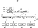
図4は、留守録電話機のハードウェアブロック図である。図4において、留守録電話機10は、バス28を介して、装置全体の制御を行うCPU21、ROM22、RAM23、音声CODEC24、不揮発性記憶装置25、入出力デバイス・インターフェース(以下、I/Fと略す)26、ネットワークI/F27が接続されている。また入出力デバイスI/Fには、スピーカ31とマイク32から構成される受話器30、ディスプレイ33、操作ボタン34が接続されている。
FIG. 4 is a hardware block diagram of the answering machine. In FIG. 4, an answering
図5は、留守録電話機の機能ブロック図である。図5において、デバイス制御部41は、入出力デバイスI/F26を介して、受話器30等の各デバイスを制御する。音声処理部42は、音声CODEC24を介して音声情報の符号化処理と符号化されたビットデータの復号化処理などを制御する。通信処理部43は、ネットワークI/F27を介してネットワークの通信処理を制御する。宛先確認部44は、SIP(Session Initiation Protocol)(以下、SIPと記す)により受信したINVITEメッセージに記述された宛先情報を読み取り、その情報に従った処理の実行を制御する。留守録処理部45は、宛先確認部44での処理結果に基づき不在メッセージの送信、メッセージ録音処理やメッセージ確認処理などの制御を行う。なお、宛先確認部44が関係する処理は、図10などで更に詳細な説明を行う。
FIG. 5 is a functional block diagram of the answering machine. In FIG. 5, the
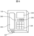
図6は、留守録電話機の斜視図である。留守録電話機10は、受話器30、ディスプレイ33、操作ボタン34、代理応答機能が割り当てられた操作ボタン35、着信時などに光で知らせるランプ36、LANケーブルを繋ぐためのLANコネクタ37などにより構成されるものである。
FIG. 6 is a perspective view of an answering machine. The answering
ここで、SIPプロトコルについて説明する。SIPプロトコルは、IP電話に代表される通話制御プロトコルの一つで、インターネットの標準化団体であるIETF(Internet Engineering Task Force)で標準化が行われ、2002年に発行されたRFC3261においてスタンダードトラックとして規定されたプロトコルであり、その後も様々な拡張がRFCとして規定されている。SIPプロトコルにおけるメッセージは、テキストで記述されシンプルで拡張性が高い。 Here, the SIP protocol will be described. The SIP protocol is one of the call control protocols typified by IP telephones, standardized by the Internet Engineering Task Force (IETF), which is an Internet standardization organization, and defined as a standard track in RFC 3261 issued in 2002. Since then, various extensions have been defined as RFCs. Messages in the SIP protocol are written in text and are simple and highly extensible.
図7を参照して、SIPメッセージにおける基本フォーマットを説明する。ここで、図7はSIPメッセージにおける基本フォーマットである。基本フォーマット100は、3段に分かれており、リクエストを表すRequest−line110、宛先や発信元などの情報が記されるHeader−Line120、処理できる機能などを記述するMessage−Body130からなる。また、Header−Line120、Message−Body130は、必要に応じて省略や拡張ができる。
With reference to FIG. 7, a basic format in the SIP message will be described. Here, FIG. 7 shows a basic format in the SIP message. The
Request−line110は、Method111と、Reqest−URI112と、SIP−Version113とから構成される。Header−Line120は、Fromヘッダ121と、Toヘッダ122、Viaヘッダ123と、Call−IDヘッダ124等から構成される。
The Request-
図8および図9を参照して、SIPプロトコルにおいてIP電話端末などから送出されるINVITEメッセージを説明する。ここで、図8はINVITEメッセージを説明する図である。図9はHistory−Infoヘッダを用いたINVITEメッセージを説明する図である。 With reference to FIGS. 8 and 9, an INVITE message transmitted from an IP telephone terminal or the like in the SIP protocol will be described. Here, FIG. 8 is a diagram for explaining the INVITE message. FIG. 9 is a diagram for explaining an INVITE message using a History-Info header.
図8において、INVITEメッセージ60の1行目にはリクエスト文が記述され、2005番への呼接続を要求する1文が記載されている。以下、Fromヘッダには発信元情報が、Toヘッダには宛先情報が示されている。このINVITEメッセージ60では、3001番から2005番への呼接続要求を意味している。
In FIG. 8, a request sentence is described in the first line of the
次に、SIPメッセージにおける発信元情報と宛先情報の特定方法について説明する。図8において、発信元情報と宛先情報をFromヘッダとToヘッダから判断したが、例えば電話の転送処理や代理受信などを行った場合、それでは必ずしも正しい情報が得られない場合がある。具体的には、呼接続に対して、2005番が応答せず図3に示す登録情報に従い2010番に不在転送された場合、Toヘッダの情報が2010番に書き換えられてしまい、受信した2010番側では元の宛先情報が判断できないという問題が起きる場合がある。しかしこの様な問題に対しては、本来の宛先情報を知らせるため手順がSIPプロトコルの拡張などで幾つか規定されており、その手法は数通りが存在している。ここでは、その幾つかの手法の中からHistory−Infoヘッダを用いた宛先情報の特定方法を用いて説明する。
Next, a method for specifying source information and destination information in the SIP message will be described. In FIG. 8, the sender information and the destination information are determined from the From header and the To header. However, for example, when telephone transfer processing or proxy reception is performed, correct information may not always be obtained. Specifically, if the
図9を参照して、History−Infoヘッダを用いたINVITEメッセージを説明する。図9において、INVITEメッセージ60Aの1行目にはリクエスト文が記述され、2010番への呼接続を要求する1文が記載されている。以下、Fromヘッダには発信元情報が、Toヘッダには宛先情報が示されている。このINVITEメッセージ60Aでは、3001番から2010番への呼接続要求に見えるが、History−Infoヘッダを参照すると、宛先情報の遷移が記録されているので、電話番号2005から電話番号2010に転送されていることが分かる。
With reference to FIG. 9, the INVITE message using the History-Info header will be described. In FIG. 9, a request sentence is described in the first line of the
次に、処理手順等を以下、図10から図13を用いて説明する。ここで、図10は、留守録電話機における着信時の処理フローチャートである。図11は留守録データ情報テーブルを説明する図である。図12は留守録電話機のディスプレイ表示である。図13は発呼電話機とテレフォニーサーバと留守録電話機との間の不在転送処理のシーケンス図である。 Next, the processing procedure and the like will be described below with reference to FIGS. Here, FIG. 10 is a process flowchart at the time of an incoming call in the answering machine. FIG. 11 is a diagram for explaining the recorded message data information table. FIG. 12 shows a display on the answering machine. FIG. 13 is a sequence diagram of the missed transfer process among the calling telephone, the telephony server, and the answering machine.
図10のフローは、留守録電話機10に電源が入り、IPアドレスや電話番号などの設定が正しく行われ、IP電話端末としての機能を始めた際に開始される。留守録電話機10は、ステップ101において、着信を示すINVITEメッセージを受信したかを判定し、受信していない場合(S101;No)は受信するまでその判定を繰り返す。留守録電話機10は、ステップ101で受信した場合は、INVITEメッセージ中にHistory−Infoヘッダがあるかの判定を行う(S102)。History−Infoヘッダがあった場合(S102;Yes)、留守録電話機10は、History−Infoヘッダに記される最初の宛先番号を取り出す(S103)。History−Infoヘッダがなかった場合(S102;No)、留守録電話機10は、Toヘッダに記される宛先番号を取り出す(S104)。
The flow of FIG. 10 is started when the answering
次に、留守録電話機10は、前処理で取り出した宛先番号が自端末の電話番号と同じかを判定し(S105)、同じだった場合(S105;Yes)、通常通りの着信音を鳴らし着呼を知らせる(S106)。一方、取り出した宛先番号が自端末の電話番号と違った場合(S105;No)、留守録電話機10は、不在転送による着信であることを知らせる通常着信音とは違うパターンの着信音を鳴らす(S107)。留守録電話機10は、ステップ106での呼出しに対してオフフックになったかの判定を行い(S108)、オフフックになった場合(S108;Yes)、相手との通話処理を開始する(S109)。一方、ステップ107での呼出しに対して、留守録電話機10は、事前に設定されている時間の間にオフフックになったかの判定を行い(S110)、もしもオフフックになった場合(S108;Yes)、留守録電話機10は、ステップ109に遷移する。
Next, the answering
オフフックにならずに設定の時間が経過した場合(S110;No)、留守録電話機10は、自動オフフックを行い(S111)、ステップ103またはステップ104で取り出した宛先情報を留守録データ情報テーブルに記録する(S112)。また、留守録電話機10は、相手へ不在メッセージを送信し(S113)、相手からのメッセージを受け付けて録音処理を行う(S114)。メッセージの録音処理が終わったら、留守録電話機10は、録音したファイルの情報や発信者情報などを留守録データ情報テーブルに紐付けして記録し(S115)、電話を切る(S117)。またステップ108にて事前に設定されている時間の間にオフフックにならない場合(S108;No)、留守録データ情報テーブルステップ111に移り留守録処理のフローに入る。
When the set time has elapsed without going off-hook (S110; No), the answering
また、ステップ109にて相手との通話の後、ステップ116においてオンフックの判定をYesの判定がでるまで行い、オンフックになった場合(S116;Yes)、ステップ117にて電話を切りフローを終える。
なお本フローにおけるステップ102から105までのステップが、図5の宛先確認部44が実施する処理となる。
In addition, after a call with the other party in
Note that steps 102 to 105 in this flow are processing performed by the
図11を参照して、図10のステップ112とステップ115にて、留守録電話機10の不揮発性記憶装置25に保存される留守録データ情報テーブルを説明する。留守録データ情報テーブル70は、図10のステップ112にて宛先番号71と、発番号通知情報から発番号72と、着信時刻73と記録される。また図10のステップ114にて、発信者からのメッセージ録音があったとき、メッセージ保存がある旨の情報をメッセージ保存74に書き込み、ステップ115にて保存されたファイル名を保存ファイル名75を記録する。これによって、ファイル名と留守録データ情報テーブル70の紐付けができる。最後の確認76の欄は、不在着信数やメッセージを利用者が確認したかどうかを記録する情報欄である。なお、この確認76の詳細利用方法や意味については、図14および図15にて記載する。
With reference to FIG. 11, the answering machine data information table stored in the
また図12は、留守録電話機10のディスプレイ33における表示であり、図10のステップ113の時点の表示を表したものである。ディスプレイ表示の最上部には、留守録着信中であることを表すメッセージが表示され、続いてステップ112にて記録された宛先情報と、発信者番号通知機能による発信者番号を表示する。これによって、複数の電話端末の留守録処理を留守録電話機10が1台で受け持っても、誰宛の不在者転送の着信で、誰から掛かってきたのかが一目で判る。このため、代理応答の必要有無が瞬時に判断できる。
FIG. 12 shows the display on the
図13を参照して、電話機B(3001番)から電話機A(2005番)へ電話を掛けるが、電話機Aが起動しておらず、留守録電話機(2010番)に不在転送されて留守録処理が行われる動作を説明する。 Referring to FIG. 13, telephone B (3001) makes a call to telephone A (2005), but telephone A is not activated and is forwarded to the answering machine (2010) so that the answering process is performed. The operation performed is described.
まず、電話機Bの利用者が電話機Aの利用者宛へ連絡するため2005番をダイヤルすると、電話機Bはテレフォニーサーバに電話番号を送信する(S201)。テレフォニーサーバは、3001番からの呼接続要求を受け、情報管理テーブル50から、2005番のアドレス解決を行うが、電話番号2005のステータス54が、Un−Regist(起動していない)状態であったため、不在転送先55の宛先を確認し(S203)、「History−Infoヘッダに2005番への呼接続処理履歴を記載して、2010番宛へ呼接続要求を送る(S204)。呼接続要求を受け取った2010番の留守録電話機10は、呼接続要求のINVITEメッセージから宛先判定を行い(S206)、その判定結果から代理応答としてオフフックする(S207)。テレフォニーサーバ11は、留守録電話機10のオフフックを受け、留守録電話機10と電話機B14とを接続する(S208)。この状態で呼接続における通話が成立する。
First, when the user of the telephone B dials the
しかし、留守録電話機10は、留守録処理のために自動で代理応答したため、呼び出し相手が不在である旨のメッセージを送信する(S210)。留守録電話機10は、相手の伝言メッセージを受け付けて録音する(S211)。その後、発呼者の操作により、電話機B14が切断要求をテレフォニーサーバ11に切断要求を送信する(S212)。テレフォニーサーバ11は、切断要求を留守録電話機10に送信する(S213)。留守録電話機10は、電話を切る(オンフック:S214)。テレフォニーサーバ11は、オフフックを電話機B14に転送し(S215)、一連の呼制御処理が完了する。
However, since the answering
上述した実施例に拠れば、テレフォニーサーバ11の情報管理テーブルの不在転送先として留守録電話機10を指定しておくだけで、適切に留守録処理が行え、さらに起動していないソフトフォン宛の電話の場合も職場の者が柔軟に代理応答することが可能となる留守録システムを提供することが出来る。
According to the above-described embodiment, it is possible to appropriately perform an answering machine only by designating the answering
最後に、留守録電話機10に記録された録音メッセージの確認方法を図14と図15を用いて説明する。ここで、図14は電話機Aと留守番電話機10との間の留守録メッセージ確認時のシーケンス図である。また、図15は留守録メッセージ確認時の留守録電話機10の処理フローチャートである。
Finally, a method for confirming the recorded message recorded on the answering
図14において、留守録電話機10は、ここでは、電話機ボタンの「*」ボタンのPB音を受信すると以降に受信した入力されたキーをコマンドとして解釈する仕様の留守録電話機であるとする。また、図示の簡便のため、テレフォニーサーバの記載を省くが、呼接続と呼切断にはテレフォニーサーバが介在する。
In FIG. 14, it is assumed here that the answering
2010番の留守録電話機を不在転送先として登録している利用者が自身宛の録音メッセージを確認するために、電話機Aを操作して、2010番に電話を掛ける。この時に電話番号に続いて「*」ボタンを押して予め決められた録音メッセージの確認コマンド(ここでは「131」とする)を押す。電話機Aは、2010*131を留守録電話機10に送信する(S301)。留守録電話機10は、コマンドを判定して録音メッセージ確認処理に入る(S302)。コマンドを受け取った留守録電話機10は、操作ユーザを確認するためにID番号(ここでは利用者の「電話番号=ID」とする)を要求する(S303。操作ユーザが自身のIDをダイヤルすると、電話機Aは、*2005を留守録電話機10に送信する(S304)。留守録電話機10は、IDを受信しIDの正当性を確認するためにパスワード(以下、PASSと略す)を要求する(S305)。操作ユーザがPASSをダイヤルすると、電話機Aは、パスワードである*139786を留守録電話機10に送信する(S306)。留守録電話機10は、PASSを受信し登録情報と照会する(S307)。ここでは、IDとPASSが合致しているので、留守録電話機10は、操作ユーザが確認していない不在着信件数と録音メッセージ件数を読みだして、電話機Aに送信する(S309)。ここで、操作ユーザがメッセージの再生要求をするコマンドを押すことにより、電話機Aは、再生要求を留守録電話機10に送信する(S310)。留守録電話機10は、再生要求コマンドを受信し、メッセージを再生する(S312)。操作ユーザはメッセージを確認し、受話器と置くのを受けて、電話機Aは、終了通知を留守録電話機10に送信する(S313)。終了通知を受信した留守録電話機10は、留守録データ情報テーブル70に確認済みを示す情報を書き込んで処理を終える。
A user who has registered the answering machine No. 2010 as a missed transfer destination operates telephone A to make a call to No. 2010 in order to confirm the recorded message addressed to himself / herself. At this time, the telephone number is followed by the “*” button to press a predetermined recording message confirmation command (here, “131”). The telephone A transmits 2010 * 131 to the answering machine 10 (S301). The answering
図15を参照して、留守録メッセージ確認時の留守録電話機10の処理フローを説明する。具体的には、図5の留守録処理部45の処理フローである。留守録電話機10が着信した際に本フローが開始される。まず、留守録処理部45は、図14で説明したコマンドを受信したかを判定し(S401)、コマンドの受信がない場合(S401;No)は本フローを終える。コマンドを受信した場合(S401;Yes)、留守録処理部45は、相手側の操作ユーザにIDの入力を要求し(S402)、その受信を判定する(S403)。IDの受信がない場合(S403;No)、留守録処理部45は、その受信を待つ。IDを受信した場合(S403;Yes)、留守録処理部45は、PASSの入力を要求し(S404)、その受信を判定する(S405)。PASSの受信がない場合(S405;No)、留守録処理部45は、その受信を待つ。PASSを受信した場合(S405;Yes)、留守録処理部45は、IDとPASSの照会を行う(S406)。留守録処理部45は、PASSが正しいか判定し(S407)、照会の結果が正しければ(S407;Yes)、該当ユーザの不在着信件数と録音メッセージ件数を通知する(S408)。照会の結果が正しくなければ(S407;No)、留守録処理部45は、本フローを終える。
With reference to FIG. 15, the processing flow of the answering
留守録処理部45は、未確認の録音メッセージがあるかを判定する(S410)。メッセージがある場合(S410;Yes)、留守録処理部45は、未確認メッセージの再生処理を行い(S411)、再生したメッセージに確認ビットを立てて(S412)、そのメッセージを削除するか確認する(S413)。ステップ413でYesなら、留守録処理部45は、メッセージファイルを消去し、No(S413;No)なら削除せず、ステップ410に戻る。未確認メッセージがなくなったら(ステップ410;No)、留守録処理部45は、未確認メッセージがない旨を通知し(S415)、電話を切り(S416)、処理を終了する。
The absence
なお、ここまでの実施例の説明では、留守録電話機は1つの呼に対して着呼処理、宛先確認の処理、留守録の処理などを説明してきたが、IP電話に於いては、音声通話中であっても、アナログ電話と違い物理回線を占有することはなく、IPネットワーク上でパケットと呼ばれる可変長のデータ単位で物理回線をシェアしながら通信を行うため、留守録電話機がマルチタスクに処理を実行することが出来れば、音声通話中に不在転送による着信が来た場合でも、留守録処理部45が自動的にその着信を受けて留守録サービスを提供したり、たまたま不在転送における着信が同時に複数呼発生した場合でも、本実施例をマルチタスクに処理させればそれぞれの呼に対して留守録サービスを提供することが可能である。
In the description of the embodiments so far, the answering machine has explained the incoming call process, the destination confirmation process, the answering process, etc. for one call. Even if the phone is in the middle, it does not occupy a physical line unlike an analog telephone, and it communicates while sharing the physical line in variable-length data units called packets on the IP network. If the process can be executed, even if an incoming call due to a missed call arrives during a voice call, the answering
また、上述した実施例に、宛先確認部44にて宛先が判明した後、通常呼出し音や代理応答呼出し音を鳴らす際に、特定の番号だけを別途指定した呼出し音を鳴らすこと、留守録処理時に相手側に不在の旨を伝える不在メッセージについて、それぞれの本留守録電話機設定者が自身の声で好きなメッセージ登録しておき、そのメッセージを相手側に再生する不在メッセージに指定することなどの応用を追加することは容易に実現可能である。
Further, in the above-described embodiment, when a normal ringing tone or a proxy response ringing tone is sounded after the destination is confirmed by the
図16を参照して、上述した実施例以外のINVITEメッセージを説明する。ここで、図16はUser−Agentヘッダを用いたINVITEメッセージを説明する図である。図16において、INVITEメッセージ60Bの1行目にはリクエスト文が記述され、2010番への呼接続を要求する1文が記載されている。以下、Fromヘッダには発信元情報が、Toヘッダには宛先情報が示されている。このINVITEメッセージ60Bでは、3001番から2010番への呼接続要求に見えるが、User−Agentヘッダを参照すると、当初の宛先情報が電話番号2005であったことが分かる。
With reference to FIG. 16, INVITE messages other than the above-described embodiment will be described. Here, FIG. 16 is a diagram for explaining an INVITE message using a User-Agent header. In FIG. 16, a request sentence is described in the first line of the
User−Agentヘッダは、本来、リクエストを開始するUAC(ユーザ・エージェント・クライアント)についての情報を示すヘッダである。しかし、セキュリティの観点からSIPにおいてはほとんど使われていない。 The User-Agent header is a header that originally indicates information about a UAC (User Agent Client) that starts a request. However, it is hardly used in SIP from the viewpoint of security.
図16において、不在転送を行う場合、テレフォニーサーバ11は、User−Agentヘッダに不在転送する前の宛先番号情報を書き込み、留守録電話機がこのフィールドを読み取ることにより、不在転送先に元の宛先番号情報を伝える事が出来る。図によれば、User−Agentヘッダには、不在転送される前の宛先番号情報が記録されている。なお、User−Agentヘッダ・フィールドの構文規則は、このヘッダが定義されているRFC2616に従った上で、テレフォニーサーバとテレフォニーサーバが管理するクライアント(電話端末)間で予め定義する。
In FIG. 16, in the case of making a call forwarding, the
他にもSIPプロトコルの大きな特徴である、“目的に応じて拡張部分を追加できる”という仕様を用いて、独自のオプションヘッダを定義してそこを利用する方法なども考えられる。 In addition, a method of defining an original option header and using it, using the specification that “an extension part can be added according to the purpose”, which is a major feature of the SIP protocol, can be considered.
10…留守録電話機、11…テレフォニーサーバ、13…PC、14…PC、15…ソフトフォン、16…ハンドセット、17…LAN、18…WAN、21…CPU、22…ROM、23…RAM、24…音声CODEC、25…不揮発性記憶装置、26…入出力デバイスI/F、27…ネットワークI/F、28…バス、30…受話器、33…ディスプレイ、34…操作ボタン、35…操作ボタン、36…ランプ、37…LANコネクタ、41…デバイス制御部、42…音声処理部、43…通信処理部、44…宛先確認部、45…留守録処理部、50…情報管理テーブル、60…INVITEメッセージ、70…留守録データ情報テーブル、100…SIP基本フォーマット。
DESCRIPTION OF
Claims (9)
前記サーバは、前記IP電話機宛ての着呼があったとき、前記IP電話機の状態を判定し、前記IP電話機が着呼できないと判定したとき、前記IP電話機の識別子を付与して前記IP代理応答電話機に前記着呼を転送し、
前記識別子は、INVITEメッセージに含まれるHistory−InfoヘッダまたはUser−Agentヘッダであり、
前記IP代理応答電話機は、着呼があったとき、前記History−Infoヘッダまたは前記User−Agentヘッダがあるか否かを判断することで転送された着呼か前記IP代理応答電話機宛ての着呼かを判定し、
前記History−Infoヘッダまたは前記User−Agentヘッダがある場合、発信者の発番号と、前記IP電話機の宛先番号とを対応付けた情報を保存し、
前記History−Infoヘッダまたは前記User−Agentヘッダがない場合、発信者の発番号と前記IP代理応答電話機の宛先番号とを対応付けた情報を保存することを特徴とする電話システム。 A telephone system comprising: an IP telephone; an IP proxy answering telephone; and a server for controlling outgoing and incoming calls of the IP telephone and the IP proxy answering telephone;
The server determines the state of the IP telephone when there is an incoming call addressed to the IP telephone, and when determining that the IP telephone cannot receive the call, assigns an identifier of the IP telephone to the IP proxy response Forward the incoming call to the phone ,
The identifier is a History-Info header or User-Agent header included in the INVITE message,
When there is an incoming call, the IP proxy answering telephone determines whether there is the History-Info header or the User-Agent header, or an incoming call directed to the IP proxy answering telephone. Determine whether
When there is the History-Info header or the User-Agent header, information that associates the calling party's calling number and the destination number of the IP telephone is stored,
When there is no History-Info header or User-Agent header , the telephone system stores information in which a caller's calling number is associated with a destination number of the IP proxy response telephone .
前記IP代理応答電話機は、着呼があったとき、転送された着呼か前記IP代理応答電話機宛ての着呼かを判定し、判定結果に基づいて鳴動音を出力することを特徴とする電話システム。 The telephone system according to claim 1,
The IP proxy answering telephone, when an incoming call is received, determines whether it is a forwarded call or an incoming call addressed to the IP proxy answering telephone, and outputs a ringing sound based on the determination result system.
前記IP代理応答電話機は、録音機能を有し、前記録音機能により録音されたデータを前記保存された情報と対応付けて保存することを特徴とする電話システム。 The telephone system according to claim 1 or 2, wherein
Telephone system the IP proxy response phone, which have a recording function, characterized in that the data recorded by the recording function stores in association with the stored information.
前記IP電話機は、コンピュータにハンドセットを接続してなることを特徴とする電話システム。 The telephone system according to any one of claims 1 to 3,
The IP telephone is a telephone system comprising a handset connected to a computer.
前記IP電話機は、前記IP代理応答電話機に対し前記IP電話機の認証操作入力を行い、前記IP電話機宛ての不在着信状態を受信することを特徴とする電話システム。 The telephone system according to any one of claims 1 to 4,
The telephone system, wherein the IP telephone performs authentication operation input of the IP telephone to the IP proxy response telephone and receives a missed call state addressed to the IP telephone.
前記テレフォニーサーバからINVITEメッセージを受信したとき、前記INVITEメッセージにHistory−InfoヘッダまたはUser−Agentヘッダが含まれているか否かを解析して、転送された着呼か前記代理応答電話機宛ての着呼かを判定し、判定結果に基づいて鳴動音を出力し、
前記History−Infoヘッダまたは前記User−Agentヘッダがある場合、前記INVITEメッセージから得た発信者の発番号と前記History−Infoヘッダまたは前記User−Agentヘッダから得た転送元電話機の宛先番号とを対応付けた情報を保存し、
前記History−Infoヘッダまたは前記User−Agentヘッダがない場合、前記INVITEメッセージから得た発信者の発番号と前記代理応答電話機の宛先番号とを対応付けた情報を保存することを特徴とする代理応答電話機。 A proxy answering telephone connected to a telephone and a telephony server via a network,
Wherein when receiving the INVITE message from the telephony server, the analyzes whether contains INVITE message to History-Info header or User-Agent header, the transferred call before or Kiyo physical response telephone addressed Determine if it is an incoming call, output a ringing sound based on the determination result ,
When there is the History-Info header or the User-Agent header, the caller's calling number obtained from the INVITE message corresponds to the destination number of the transfer source telephone obtained from the History-Info header or the User-Agent header. Save the information
In the absence of the History-Info header or the User-Agent header , the proxy response is characterized by storing information in which the caller's calling party number obtained from the INVITE message is associated with the destination number of the proxy response telephone. Phone.
前記判定結果に基づいてディスプレイ表示を出力することを特徴とする代理応答電話機。 The proxy answering telephone according to claim 6 ,
A proxy answering telephone that outputs a display on the basis of the determination result.
一定期間前記鳴動音を出力した後、応答メッセージを送出し、録音モードに切替えることを特徴とする代理応答電話機。 The proxy answering telephone set according to claim 6 or 7 ,
A proxy answering telephone, which outputs a ringing sound for a certain period of time and then sends a response message to switch to a recording mode.
前記代理応答電話は、前記転送元電話機から認証操作入力を受信すると、前記転送元電話機宛ての不在着信状態を前記転送元電話機に送信することを特徴とする代理応答電話機。 The proxy answering telephone according to any one of claims 6 to 8,
When the proxy answering telephone receives an authentication operation input from the transfer source telephone, the proxy answer telephone transmits a missed call state addressed to the transfer source telephone to the transfer source telephone.
Priority Applications (4)
| Application Number | Priority Date | Filing Date | Title |
|---|---|---|---|
| JP2007180897A JP4920516B2 (en) | 2007-07-10 | 2007-07-10 | Telephone system and proxy answering phone |
| EP08011731A EP2015551A3 (en) | 2007-07-10 | 2008-06-27 | Telephone system, server and proxy response telephone |
| US12/169,084 US8208411B2 (en) | 2007-07-10 | 2008-07-08 | Telephone system, server and proxy response telephone |
| CN2008101280127A CN101345798B (en) | 2007-07-10 | 2008-07-09 | Telephone system, server and proxy response telephone |
Applications Claiming Priority (1)
| Application Number | Priority Date | Filing Date | Title |
|---|---|---|---|
| JP2007180897A JP4920516B2 (en) | 2007-07-10 | 2007-07-10 | Telephone system and proxy answering phone |
Publications (3)
| Publication Number | Publication Date |
|---|---|
| JP2009021669A JP2009021669A (en) | 2009-01-29 |
| JP2009021669A5 JP2009021669A5 (en) | 2010-03-04 |
| JP4920516B2 true JP4920516B2 (en) | 2012-04-18 |
Family
ID=39869752
Family Applications (1)
| Application Number | Title | Priority Date | Filing Date |
|---|---|---|---|
| JP2007180897A Active JP4920516B2 (en) | 2007-07-10 | 2007-07-10 | Telephone system and proxy answering phone |
Country Status (4)
| Country | Link |
|---|---|
| US (1) | US8208411B2 (en) |
| EP (1) | EP2015551A3 (en) |
| JP (1) | JP4920516B2 (en) |
| CN (1) | CN101345798B (en) |
Families Citing this family (9)
| Publication number | Priority date | Publication date | Assignee | Title |
|---|---|---|---|---|
| CN101795391B (en) * | 2010-04-15 | 2014-07-16 | 中兴通讯股份有限公司 | Message playing method used for video conference and video conference system |
| CN103259940A (en) * | 2012-02-20 | 2013-08-21 | 联想(北京)有限公司 | Communication terminal and message data transmission method |
| JP5827703B2 (en) | 2013-02-26 | 2015-12-02 | 富士フイルム株式会社 | Chromatographic method, chromatographic kit, and method for producing chromatographic insoluble carrier |
| CN103929555B (en) * | 2014-04-28 | 2016-03-09 | 广东佳和通信技术有限公司 | A kind of IP recording system voice flow mirror method |
| US10362121B1 (en) | 2014-07-10 | 2019-07-23 | Mitel Networks, Inc. | Communications path verification |
| US10375127B2 (en) | 2017-08-29 | 2019-08-06 | T-Mobile Usa, Inc. | System and method for preventing robocall voicemail deposit |
| CN107645582B (en) * | 2017-09-04 | 2021-01-26 | 深圳市盛路物联通讯技术有限公司 | Information changing method, terminal equipment and computer readable medium |
| CN112400307B (en) * | 2018-08-01 | 2022-07-15 | 瑞典爱立信有限公司 | Enhanced built-in voicemail for user devices |
| JP7400836B2 (en) * | 2020-01-06 | 2023-12-19 | 日本電信電話株式会社 | Call alert device, call alert system, call alert method, and call alert program |
Family Cites Families (33)
| Publication number | Priority date | Publication date | Assignee | Title |
|---|---|---|---|---|
| JP2723222B2 (en) | 1987-03-31 | 1998-03-09 | 株式会社東芝 | Communication terminal device |
| JPH0563827A (en) * | 1991-09-04 | 1993-03-12 | Nec Corp | Telephone reception system |
| JPH0595422A (en) | 1991-10-02 | 1993-04-16 | Fujitsu Ltd | Cluster absence transfer system |
| US6101249A (en) * | 1997-08-27 | 2000-08-08 | Lucent Technologies, Inc. | Automatic call screening telecommunication device |
| JPH11234410A (en) | 1998-02-18 | 1999-08-27 | Nitsuko Corp | Key telephone system |
| JP2000013826A (en) * | 1998-06-26 | 2000-01-14 | Nakayo Telecommun Inc | Key telephone set provided with function handling power failure |
| JP2000125016A (en) * | 1998-10-14 | 2000-04-28 | Nec Yonezawa Ltd | System and method for informing automatic transfer information to terminal having display window stored in private exchange |
| US20020181694A1 (en) * | 2001-05-31 | 2002-12-05 | Mani Babu V. | Distinctive call notification service in a multimedia-capable netwok |
| JP4102555B2 (en) | 2001-09-28 | 2008-06-18 | Necインフロンティア株式会社 | Voice mail implementation method and system using the method |
| US20030135624A1 (en) * | 2001-12-27 | 2003-07-17 | Mckinnon Steve J. | Dynamic presence management |
| JP3809907B2 (en) | 2002-08-29 | 2006-08-16 | 株式会社日立コミュニケーションテクノロジー | IP private branch exchange system and IP telephone |
| US6904140B2 (en) * | 2002-12-17 | 2005-06-07 | Nokia Corporation | Dynamic user state dependent processing |
| US7742589B2 (en) * | 2003-11-10 | 2010-06-22 | At&T Intellectual Property I, Lp | Distinctive call waiting based on a redirecting number |
| CN1894948B (en) * | 2003-11-20 | 2010-11-10 | 意大利电信股份公司 | Method and system for retransmitting telephone call to honeycomb telephone set |
| US7804949B2 (en) * | 2003-12-31 | 2010-09-28 | Alcatel Lucent | Client-based integration of PBX and messaging systems |
| JP2005217643A (en) * | 2004-01-28 | 2005-08-11 | Sanyo Electric Co Ltd | Telephone receiver and telephone server |
| JP2005318503A (en) * | 2004-03-29 | 2005-11-10 | Hitachi Ltd | Presence server, session control server, packet relay system, server, and system |
| JP4426922B2 (en) * | 2004-08-04 | 2010-03-03 | パナソニック株式会社 | IP telephone system, IP telephone apparatus, and message recording method |
| JP2006081088A (en) | 2004-09-13 | 2006-03-23 | Fr Telecom | Voice mail system |
| JP2005031700A (en) * | 2004-09-27 | 2005-02-03 | Seiko Epson Corp | Display drive circuit, display panel and display device |
| US7436820B2 (en) * | 2004-09-29 | 2008-10-14 | Lucent Technologies Inc. | Method and apparatus for providing fault tolerance to intelligent voice-over-IP endpoint terminals |
| US7720213B2 (en) * | 2004-12-30 | 2010-05-18 | Alcatel Lucent | Parameter dependent ring tones |
| JP4167661B2 (en) | 2005-02-02 | 2008-10-15 | Necパーソナルプロダクツ株式会社 | Telephone system and telephone transfer method |
| US20060252417A1 (en) | 2005-05-05 | 2006-11-09 | Avaya Technology Corp. | Changing the user interface at a telecommunications terminal |
| KR101042058B1 (en) | 2005-06-01 | 2011-06-16 | 산요덴키 콘슈머 일렉트로닉스 가부시키가이샤 | Telephone and telephone control method |
| JP2007020084A (en) * | 2005-07-11 | 2007-01-25 | Fujitsu Ltd | Common management system of ip telephone |
| JP4722623B2 (en) * | 2005-08-24 | 2011-07-13 | パナソニック株式会社 | IP communication apparatus and control method thereof |
| US20070077920A1 (en) * | 2005-09-15 | 2007-04-05 | Phillip Weeks | Methods, systems and computer program products for aggregating communications and media data |
| CN1812454A (en) * | 2006-02-23 | 2006-08-02 | 魏志亮 | Method for sending out calling when telephone called |
| US9054909B2 (en) * | 2006-06-30 | 2015-06-09 | Microsoft Technology Licensing, Llc | Forwarding calls in real time communications |
| US20080009269A1 (en) * | 2006-07-10 | 2008-01-10 | New I.P. Investments, Llc | Method and system for management and routing of telecommunications on data and telephone lines |
| US8718257B2 (en) * | 2006-07-10 | 2014-05-06 | Francesco Ricci | Systems and methods for providing answering services |
| US8116441B2 (en) * | 2007-03-23 | 2012-02-14 | Verizon Patent And Licensing Inc. | Call routing based on physical location of called party |
-
2007
- 2007-07-10 JP JP2007180897A patent/JP4920516B2/en active Active
-
2008
- 2008-06-27 EP EP08011731A patent/EP2015551A3/en not_active Withdrawn
- 2008-07-08 US US12/169,084 patent/US8208411B2/en active Active
- 2008-07-09 CN CN2008101280127A patent/CN101345798B/en not_active Expired - Fee Related
Also Published As
| Publication number | Publication date |
|---|---|
| US20090016242A1 (en) | 2009-01-15 |
| EP2015551A3 (en) | 2011-05-04 |
| US8208411B2 (en) | 2012-06-26 |
| CN101345798A (en) | 2009-01-14 |
| JP2009021669A (en) | 2009-01-29 |
| CN101345798B (en) | 2013-07-10 |
| EP2015551A2 (en) | 2009-01-14 |
Similar Documents
| Publication | Publication Date | Title |
|---|---|---|
| JP4920516B2 (en) | Telephone system and proxy answering phone | |
| JP4139031B2 (en) | Caller information display method | |
| CN101330541B (en) | System and method for automatic call back using availabilityinformation | |
| JP4944415B2 (en) | COMMUNICATION SYSTEM, PRESENCE SERVER, AND COMMUNICATION METHOD USED FOR THEM | |
| JP4379801B2 (en) | Instant messaging with PBX stations | |
| JP5232173B2 (en) | Server apparatus and message transmission method | |
| US20050008137A1 (en) | Telephone exchange apparatus and telephone exchange system | |
| JP4672011B2 (en) | IP telephone system and IP telephone method | |
| JPWO2007037155A1 (en) | Telephone terminal having presence change function and presence system using the telephone terminal | |
| JP5195431B2 (en) | Telephone relay system, telephone relay apparatus, and telephone relay method | |
| JP4667526B2 (en) | Cooperation apparatus, cooperation system, and computer program | |
| JP2008085901A (en) | Telephone switching system, and service provision method for use in the same telephone switching system | |
| JP2006270525A (en) | Telephone system | |
| JP7436952B2 (en) | Telephone systems and telephone controls | |
| JP2010141416A (en) | Telephone device having message mail transmission function | |
| JP7523004B2 (en) | Telephone System | |
| CN1988456A (en) | Proxy response terminal and system | |
| JP2006121470A (en) | Telephone communication system and information processing terminal used for the same, telephone communication control method and program for controlling telephone communication | |
| JP7335548B2 (en) | Telephone control device and telephone control method | |
| JP6891771B2 (en) | Telephone system and telephone controller | |
| JP2019114995A (en) | Telephone control device and telephone control program | |
| JP7513949B2 (en) | Telephone control device and telephone system | |
| JP2011182347A (en) | Telephone system, communication terminal, server device and redial notification method | |
| JP2008148202A (en) | Voice mail apparatus | |
| WO2002033943A1 (en) | Answer-phone message providing system |
Legal Events
| Date | Code | Title | Description |
|---|---|---|---|
| A521 | Written amendment |
Free format text: JAPANESE INTERMEDIATE CODE: A523 Effective date: 20100119 |
|
| A621 | Written request for application examination |
Free format text: JAPANESE INTERMEDIATE CODE: A621 Effective date: 20100119 |
|
| A977 | Report on retrieval |
Free format text: JAPANESE INTERMEDIATE CODE: A971007 Effective date: 20110929 |
|
| A131 | Notification of reasons for refusal |
Free format text: JAPANESE INTERMEDIATE CODE: A131 Effective date: 20111004 |
|
| A521 | Written amendment |
Free format text: JAPANESE INTERMEDIATE CODE: A523 Effective date: 20111130 |
|
| TRDD | Decision of grant or rejection written | ||
| A01 | Written decision to grant a patent or to grant a registration (utility model) |
Free format text: JAPANESE INTERMEDIATE CODE: A01 Effective date: 20120105 |
|
| A01 | Written decision to grant a patent or to grant a registration (utility model) |
Free format text: JAPANESE INTERMEDIATE CODE: A01 |
|
| A61 | First payment of annual fees (during grant procedure) |
Free format text: JAPANESE INTERMEDIATE CODE: A61 Effective date: 20120201 |
|
| R150 | Certificate of patent or registration of utility model |
Ref document number: 4920516 Country of ref document: JP Free format text: JAPANESE INTERMEDIATE CODE: R150 Free format text: JAPANESE INTERMEDIATE CODE: R150 |
|
| FPAY | Renewal fee payment (event date is renewal date of database) |
Free format text: PAYMENT UNTIL: 20150210 Year of fee payment: 3 |