JP4920175B2 - PHOTOGRAPHIC PRINT DEVICE, PHOTOGRAPHIC PRINT DEVICE CONTROL METHOD, PHOTOGRAPHIC PRINT DEVICE CONTROL PROGRAM, AND COMPUTER READABLE RECORDING MEDIUM - Google Patents
PHOTOGRAPHIC PRINT DEVICE, PHOTOGRAPHIC PRINT DEVICE CONTROL METHOD, PHOTOGRAPHIC PRINT DEVICE CONTROL PROGRAM, AND COMPUTER READABLE RECORDING MEDIUM Download PDFInfo
- Publication number
- JP4920175B2 JP4920175B2 JP2004083659A JP2004083659A JP4920175B2 JP 4920175 B2 JP4920175 B2 JP 4920175B2 JP 2004083659 A JP2004083659 A JP 2004083659A JP 2004083659 A JP2004083659 A JP 2004083659A JP 4920175 B2 JP4920175 B2 JP 4920175B2
- Authority
- JP
- Japan
- Prior art keywords
- image
- range
- unit
- user
- printing apparatus
- Prior art date
- Legal status (The legal status is an assumption and is not a legal conclusion. Google has not performed a legal analysis and makes no representation as to the accuracy of the status listed.)
- Expired - Lifetime
Links
Images


Classifications
-
- Y—GENERAL TAGGING OF NEW TECHNOLOGICAL DEVELOPMENTS; GENERAL TAGGING OF CROSS-SECTIONAL TECHNOLOGIES SPANNING OVER SEVERAL SECTIONS OF THE IPC; TECHNICAL SUBJECTS COVERED BY FORMER USPC CROSS-REFERENCE ART COLLECTIONS [XRACs] AND DIGESTS
- Y02—TECHNOLOGIES OR APPLICATIONS FOR MITIGATION OR ADAPTATION AGAINST CLIMATE CHANGE
- Y02P—CLIMATE CHANGE MITIGATION TECHNOLOGIES IN THE PRODUCTION OR PROCESSING OF GOODS
- Y02P20/00—Technologies relating to chemical industry
- Y02P20/50—Improvements relating to the production of bulk chemicals
- Y02P20/52—Improvements relating to the production of bulk chemicals using catalysts, e.g. selective catalysts
Landscapes
- Cameras Adapted For Combination With Other Photographic Or Optical Apparatuses (AREA)
- Studio Devices (AREA)
Description
本発明は、利用者の写真撮影を行うとともに、その写真を背景画像などと合成した上でプリント出力する写真撮影プリント装置、写真撮影プリント装置の制御方法、写真撮影プリント装置の制御プログラム、およびコンピュータ読み取り可能な記録媒体に関するものである。 The present invention relates to a photographic printing apparatus that takes a photograph of a user and prints the photograph after combining it with a background image, a method for controlling the photographic printing apparatus, a control program for the photographic printing apparatus, and a computer The present invention relates to a readable recording medium.
従来、例えばゲームセンターなどの娯楽施設において、利用者の写真撮影を行うとともに、その写真を背景画像などと合成した上でシールプリントとして出力する写真撮影プリント装置(写真画像編集印刷装置、写真シール機)が設置されており、人気を博している。この写真撮影プリント装置には、例えば、硬貨を投入した後、利用者が筐体内に設置された背景用のカーテンから好みの色を引き出して背景を変化させ、更に、美白等の効果を施すために用意された様々なライティング効果を選択することによって、高解像度のCCD(Charge Coupled Device)カメラの性能を生かした高画質の撮影を行うことができるものがある。また、液晶パネル上に表示した撮影画像に対し、利用者が付属ペン・指・スタンプ等を用いて、任意あるいは所定の文字・図形等の書き込みや編集を行うことにより、個性的な編集画像を作成し、それをシール紙等に印刷する写真撮影プリント装置が存在している。 2. Description of the Related Art Conventionally, in a recreational facility such as a game center, a photographic printing apparatus (photo image editing and printing apparatus, photographic seal machine) that takes a photograph of a user and combines the photograph with a background image and outputs it as a seal print ) Is installed and is gaining popularity. In this photography printing apparatus, for example, after a coin is inserted, the user draws a favorite color from a background curtain installed in the casing to change the background, and further, for effecting whitening and the like By selecting the various lighting effects prepared in the above, there are some that can perform high-quality shooting using the performance of a high-resolution CCD (Charge Coupled Device) camera. In addition, a user can write or edit an arbitrary or predetermined character, figure, etc. with a pen, finger, stamp, etc. on the captured image displayed on the liquid crystal panel, thereby creating a unique edited image. There is a photographic printing apparatus that creates and prints it on sticker paper or the like.
このような写真プリント撮影装置には、被写体が適切な位置、範囲内に居るかをセンサで自動的検出し、適切な位置で撮影した画像と、他の画像と合成して出力することができるものもある(例えば、特許文献1参照)。また、複数のカメラでもって変化に富んだカメラアングルでの撮影を可能にし、被写体が自らの姿を確認しながら撮影することができるものもある(例えば、特許文献2参照)。また、例えば照明写真を写すような写真撮影プリント装置には、ユーザ自身が正確な位置合わせをし易くした撮影用ガイドがあるもの(例えば、特許文献3参照)や、利用者が撮像位置に立つと自動的に位置検知をし、利用者が好ましい位置になるようカメラ位置を移動させるものある(例えば、特許文献4参照)。 In such a photo print photographing apparatus, it is possible to automatically detect whether or not the subject is in an appropriate position and range by a sensor and to combine and output an image photographed at an appropriate position with another image. There are some (see, for example, Patent Document 1). In addition, there is a camera that enables shooting with a variety of camera angles using a plurality of cameras, and allows a subject to take a picture while checking his / her appearance (see, for example, Patent Document 2). Further, for example, in a photographic printing apparatus that takes a photograph of an illumination, there is a photographic guide that facilitates accurate positioning by the user (see, for example, Patent Document 3), and the user stands at the imaging position. The position of the camera is automatically detected, and the camera position is moved so that the user has a preferable position (see, for example, Patent Document 4).
このような写真撮影プリント装置は、利用者の大半が女子高生で占められており、放課後や休日には友人とプレイして写真シールを交換するなど、携帯電話による会話やメールと共に重要なコミュニケーションの1つとなっている。さらに1日に何度も利用するという利用者が多い。そのため、単に顔や全身の写真を撮影するだけの画一的なものでは飽きられることが多い。よって、従来のような撮影や画像編集といった遊びの他に、新たな遊びが求められている。
上記のような写真撮影プリント装置は、撮影に際し、タッチパネル等の画像表示部に表示された画像の所定の範囲を撮影画像とした場合には、カメラ装置が左右、上下、前後に移動できるようにっており、また、カメラ装置におけるズーム機構を用いて写真撮影を行っていた。そのため、カメラにおける機械的要素が増えて製造コスト増大に繋がっている。 The above-described photography printing apparatus allows the camera device to move left and right, up and down, and back and forth when taking a predetermined range of an image displayed on an image display unit such as a touch panel when photographing. In addition, photography was performed using a zoom mechanism in the camera device. For this reason, mechanical elements in the camera increase, leading to an increase in manufacturing cost.
本発明は、上記の問題に鑑みてなされたものであり、カメラ装置の複雑な機構によらなくても所定の範囲の撮影画像を作成することができる写真撮影プリント装置、写真撮影プリント装置の制御方法、写真撮影プリント装置の制御プログラム、およびコンピュータ読み取り可能な記録媒体を実現することにある。 The present invention has been made in view of the above-described problem, and can control a photographic printing apparatus and a photographic printing apparatus that can create a photographic image within a predetermined range without using a complicated mechanism of the camera apparatus. A method, a control program for a photographic printing apparatus, and a computer-readable recording medium.
本発明に係る写真撮影プリント装置は、上記課題を解決するために、被写体の撮影を行う撮影部と、当該撮影部で撮影されている動画像をリアルタイムで表示する画像表示部と、当該撮影部によって写真撮影された撮影画像に基づいて形成される画像をプリント媒体に対して出力する画像出力部とを備えた写真撮影プリント装置であって、上記画像表示部における所定の範囲を指定する範囲指定手段と、上記範囲指定手段で指定された指定範囲の画像を上記撮影画像として作成する撮影画像作成手段とを備えることを特徴としている。 In order to solve the above-described problem, a photography printing apparatus according to the present invention includes a photographing unit that photographs a subject, an image display unit that displays a moving image captured by the photographing unit in real time, and the photographing unit. An image output unit that outputs an image formed on the basis of a photographed image taken by the image output unit to a print medium, wherein the range designation designates a predetermined range in the image display unit And a photographed image creation means for creating an image of the designated range designated by the range designation means as the photographed image.
また、本発明に係る写真撮影プリント装置の制御方法は、上記課題を解決するために、被写体の撮影を行う撮影部と、当該撮影部で撮影されている動画像をリアルタイムで表示する画像表示部と、当該撮影部によって写真撮影された撮影画像に基づいて形成される画像をプリント媒体に対して出力する画像出力部とを備えた写真撮影プリント装置の制御方法であって、上記画像表示部における所定の範囲を指定する範囲指定ステップと、上記範囲指定ステップにて指定された指定範囲の画像を上記撮影画像として作成する撮影画像作製ステップとを含むことを特徴としている。 In addition, in order to solve the above problems, a control method for a photographic printing apparatus according to the present invention includes a photographing unit that photographs a subject, and an image display unit that displays a moving image photographed by the photographing unit in real time. And a control method for a photographic printing apparatus comprising: an image output unit that outputs an image formed based on a photographed image photographed by the photographing unit to a print medium, wherein the image display unit includes: It includes a range designating step for designating a predetermined range, and a photographed image producing step for creating an image of the designated range designated in the range designating step as the photographed image.
上記構成および上記方法によると、画像表示部全体の撮影画像ではなく、指定したの範囲のみ撮影画像を作成することができる。ここで、画像表示部とは、撮影部で撮影されている動画像をリアルタイムで表示する画像表示装置における、いわゆる画面を指すものとする。 According to the configuration and the method described above, it is possible to create a captured image only in a specified range, not a captured image of the entire image display unit. Here, the image display unit refers to a so-called screen in an image display device that displays a moving image captured by the imaging unit in real time.
従来の写真撮影プリント装置では、所定の範囲の撮影画像を作成したい場合には、撮影部が左右、上下、前後に移動できるようなっており、また、撮影部におけるズーム機構を用いて写真撮影を行っていた。しかし、本発明によると、このような撮影部の複雑な機構によらなくても指定の範囲の撮影画像を作成することができる。そのため、撮影部における機械的要素のコストを削減することができるという効果を奏する。また、従来の写真撮影プリント装置にない撮影方法を提供することができるという効果を奏する。 In a conventional photo printing apparatus, when it is desired to create a photographed image within a predetermined range, the photographing unit can be moved left and right, up and down, and back and forth. I was going. However, according to the present invention, it is possible to create a photographed image in a specified range without using such a complicated mechanism of the photographing unit. As a result, the cost of mechanical elements in the photographing unit can be reduced. In addition, there is an effect that it is possible to provide a photographing method that is not available in the conventional photography printing apparatus.
また、撮影部に近づくことで拡大させた撮影画像を得るような場合には照明の効果を減少させることが従来あったが、上記構成によるとこのような不具合を起こすこともなく、拡大された撮影画像を形成することができる。 In addition, in the case where an enlarged photographed image is obtained by approaching the photographing unit, the effect of illumination has been reduced in the past, but according to the above configuration, it was enlarged without causing such a problem. A photographed image can be formed.
本発明に係る写真撮影プリント装置では、上記構成に加え、上記範囲指定手段で指定された指定範囲を、上記画像表示部に表示される上記動画像に重畳させて表示させる表示制御手段を備えてもよい。 In addition to the above-described configuration, the photography printing apparatus according to the present invention further includes display control means for displaying the designated range designated by the range designation means so as to be superimposed on the moving image displayed on the image display unit. Also good.
また、本発明に係る写真撮影プリント装置の制御方法は、上記方法に加え、上記範囲指定ステップで指定された指定範囲を、上記画像表示部に表示される上記動画像に重畳させて表示させる表示制御ステップを含んでもよい。 In addition to the above method, the control method of the photographic printing apparatus according to the present invention includes a display for displaying the specified range specified in the range specifying step so as to be superimposed on the moving image displayed on the image display unit. A control step may be included.
上記構成および方法によると、指定範囲を動画像に重畳させて表示することができる。そのため、利用者は指定範囲を、撮影部で撮影され画像表示部にリアルタイムで表示される動画像、すなわちライブビュー画面を確認しながら、写真撮影を行うことができる。 According to the above configuration and method, the designated range can be displayed superimposed on the moving image. Therefore, the user can take a picture of the specified range while confirming a moving image that is shot by the shooting unit and displayed in real time on the image display unit, that is, a live view screen.
本発明に係る写真撮影プリント装置では、上記構成に加え、上記表示制御手段は、上記指定範囲内の画像を拡大して上記画像表示部に表示させてもよい。 In the photographic printing apparatus according to the present invention, in addition to the above configuration, the display control means may enlarge an image within the specified range and display it on the image display unit.
また、本発明に係る写真撮影プリント装置の制御方法は、上記方法に加え、上記表示制御ステップでは、上記指定範囲内の画像を拡大して上記画像表示部に表示させてもよい。 In addition to the above method, the control method of the photographic printing apparatus according to the present invention may enlarge the image within the designated range and display it on the image display unit in the display control step.
上記構成および方法によると、指定範囲内の画像を拡大して画像表示部に表示されるので、利用者は、作成される撮影画像をライブビュー画像で、拡大して確認することができる。そのため、利用者は、そのライブビュー画像を見て、表情や姿勢を変えることができるので、表情や姿勢の細かい部分まで好みに変更して写真撮影することができる。 According to the above configuration and method, the image within the specified range is enlarged and displayed on the image display unit, so that the user can enlarge and check the created captured image with the live view image. Therefore, the user can change the facial expression and posture by looking at the live view image, so that the user can change the facial expression and the posture with fine details and take a picture.
本発明に係る写真撮影プリント装置では、上記構成に加え、上記範囲指定手段は、上記画像表示部で範囲を変更して指定してもよい。 In the photographic printing apparatus according to the present invention, in addition to the above configuration, the range specifying means may specify the range by changing the range on the image display unit.
また、本発明に係る写真撮影プリント装置の制御方法は、上記方法に加え、上記範囲指定ステップでは、上記画像表示部で範囲を移動させて指定してもよい。 In addition to the above method, the control method of the photographic printing apparatus according to the present invention may be specified by moving the range on the image display unit in the range specifying step.
上記構成および方法によると、撮影画像が作成される指定範囲が移動する。例えば、この指定範囲がランダムに移動する場合、利用者は予想外の撮影画像を取得することになる。そのため、利用者に、単なる写真撮影だけでなく、楽しみをもった撮影を提供することができる。よって、顧客拡大に繋げることができる。 According to the above configuration and method, the designated range in which the captured image is created moves. For example, when the designated range moves randomly, the user acquires an unexpected captured image. Therefore, it is possible to provide the user with fun photography as well as simple photography. Therefore, it can lead to customer expansion.
本発明に係る写真撮影プリント装置では、上記構成に加え、利用者による利用者操作を受け付けて情報を取得する入力部を備え、上記範囲指定手段は、上記入力部が取得した情報に基づいて範囲を指定してもよい。 In addition to the above-described configuration, the photography printing apparatus according to the present invention includes an input unit that receives a user operation by a user and acquires information, and the range specifying unit includes a range based on information acquired by the input unit. May be specified.
また、本発明に係る写真撮影プリント装置の制御方法は、上記方法に加え、上記写真プリント装置は、利用者による利用者操作を受け付けて情報を取得する入力部を備え、上記範囲指定ステップでは、上記入力部が取得した情報に基づいて範囲を指定してもよい。 Further, in addition to the above method, the photo printing apparatus according to the present invention includes an input unit that receives a user operation by a user and acquires information, and in the range specifying step, The range may be specified based on the information acquired by the input unit.
上記構成および方法によると、利用者は、入力部から簡易に範囲を指定することができる。また、利用者は、ライブビュー画面を確認しながら、入力部を用いて好みの範囲を指定することができる。そのため、利用者は、好みの範囲の画像を撮影画像として取得することができる。 According to the above configuration and method, the user can easily specify a range from the input unit. Also, the user can specify a favorite range using the input unit while checking the live view screen. Therefore, the user can acquire an image in a favorite range as a captured image.
なお、写真撮影プリント装置は、コンピュータにより実現してもよく、この場合には、コンピュータを上記各手段として動作させることにより上記写真撮影プリント装置をコンピュータにて実現させる写真撮影プリント装置の制御プログラム、及びその写真撮影プリント装置の制御プログラムを記録したコンピュータ読み取り可能な記録媒体も、本発明の範疇に入る。 The photography printing apparatus may be realized by a computer. In this case, a control program for the photography printing apparatus that causes the photography printing apparatus to be realized by the computer by operating the computer as each of the above means, In addition, a computer-readable recording medium that records a control program for the photography printing apparatus also falls within the scope of the present invention.
これらの構成によれば、写真撮影プリント装置の制御プログラムを、コンピュータに読み取り実行させることによって、上記写真撮影プリント装置と同一の作用効果を実現することができる。 According to these structures, the same operation effect as the said photography printing apparatus can be implement | achieved by making a computer read and execute the control program of photography photography printing apparatus.
本発明に係る写真撮影プリント装置は、以上のように、制御手段が、上記画像表示部における所定の範囲を指定する範囲指定手段と、上記範囲指定手段で指定された指定範囲の撮影画像を作成する撮影画像作成手段とを備えている。 In the photographic printing apparatus according to the present invention, as described above, the control unit creates a range designation unit for designating a predetermined range in the image display unit, and a photographic image in the designated range designated by the range designation unit. Photographed image creating means.
上記構成によると、画像表示部全体の撮影画像ではなく、範囲指定手段が指定したの範囲のみ撮影画像を作成することができる。よって、撮影部の複雑な機構によらなくても指定の範囲の撮影画像を作成することができる。そのため、撮影部における機械的要素のコストを削減することができるという効果を奏する。また、従来の写真撮影プリント装置にない撮影方法を提供することができるという効果を奏する。 According to the above configuration, it is possible to create a captured image only in the range designated by the range designating unit, not the captured image of the entire image display unit. Therefore, a photographed image in a specified range can be created without using a complicated mechanism of the photographing unit. As a result, the cost of mechanical elements in the photographing unit can be reduced. In addition, there is an effect that it is possible to provide a photographing method that is not available in the conventional photography printing apparatus.
また、撮影部に近づくことで拡大させた撮影画像を得るような場合には照明の効果を減少させることが従来あったが、上記構成によるとこのような不具合を起こすこともなく、拡大された撮影画像を形成することができる。 In addition, in the case where an enlarged photographed image is obtained by approaching the photographing unit, the effect of illumination has been reduced in the past, but according to the above configuration, it was enlarged without causing such a problem. A photographed image can be formed.
また、本発明に係る、写真撮影プリント装置の制御方法、写真撮影プリント装置の制御プログラム、コンピュータ読み取り可能な記録媒体も、同一の効果を実現できる。 In addition, the control method for the photographic printing apparatus, the control program for the photographic printing apparatus, and the computer-readable recording medium according to the present invention can realize the same effect.
〔実施の形態1〕
本発明の実施の一形態について図1〜図3に基づいて説明すれば、以下のとおりである。本実施形態に係る写真撮影プリント装置1は、利用者の写真を撮影する機能(撮影機能)、撮影した写真に対して落書きなどの編集を利用者に行わせる機能(編集機能)、及び編集された画像をプリントする機能(プリント機能)を備えているものである。なお、これらの機能は全て必須であるものではなく、例えば編集機能が省かれた構成とすることも可能である。
[Embodiment 1]
An embodiment of the present invention will be described below with reference to FIGS. The photography printing apparatus 1 according to the present embodiment has a function for photographing a user's photograph (photographing function), a function for allowing a user to edit graffiti etc. on the photographed photograph (editing function), and editing. It has a function (printing function) for printing a printed image. Note that all these functions are not essential, and for example, a configuration in which the editing function is omitted may be employed.
(写真撮影プリント装置の外観的構成)
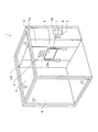
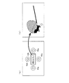
まず、図2を参照しながら、写真撮影プリント装置1の外観について説明する。図2は、本実施形態に係る写真撮影プリント装置1斜視図である。図2に示すように、利用者を被写体として撮影するカメラユニット(撮影部)2を備える装置本体3と、被写体の背景となる背景シート4とが配備されている。なお、装置本体3から背景シート4までの周囲および上部は、外部からの光を遮断する遮光幕によって覆われる。これにより利用者の写真を撮影する撮影空間5が形成される。この写真撮影プリント装置1は撮影空間5にて編集処理も行われるものとするが、撮影空間と編集処理を行う空間とが別々に設けられていてもかまわない。
(Appearance structure of photo printing device)
First, the external appearance of the photographic printing apparatus 1 will be described with reference to FIG. FIG. 2 is a perspective view of the photographic printing apparatus 1 according to the present embodiment. As shown in FIG. 2, an apparatus
装置本体3には、カメラユニット2、タッチパネル(画像表示部)6、硬貨投入口7、硬貨返却口8、撮影後のプリントが排出されるプリント排出口9が設けられているが備えられている。また、装置本体3には、被写体を照明する照明装置10として、蛍光灯、ストロボランプ、反射板(これらは、装置本体3内に設置されているため、図示せず)、および拡散板11a・11bが配備される。なお、照明装置10の構成は上記には限定されない。また、タッチパネル付近にはタッチペン12a・12bが設けられている。また、撮影空間5内に、スピーカ(図示せず)が配備されている。
The apparatus
また、写真撮影プリント装置1には、撮影空間5に利用者がいることを撮影空間5の外に向けて表示するためのランプ等が外側に設けられていてもかまわない。また、撮影空間5に荷物置スペースや荷物掛けフック等が設けられていると、利用者は荷物を視界内に入れることができるので、置き引きを防止することができる。なお、上記設置物の配置位置は図面のものに限定されない。
Further, the photographic printing apparatus 1 may be provided with a lamp or the like on the outside for displaying that the user is in the
タッチパネル6は、例えば液晶表示素子などのフラットパネルディスプレイやCRT(cathode ray tube)等の表示面にタッチセンサを設けて構成されている。このタッチパネル6には、撮影処理および編集処理における各種メッセージや画像などが表示される。具体的には、タッチパネル6には、デモ画面、オープニング画面、課金処理指示画面、撮影処理および編集処理における各種操作内容等のメッセージや画像、落書きなどの画像編集処理時における編集対象の画像および各種編集ツールなどが表示される。また、撮影時の動画像等が表示される。これにより、カメラユニット2に向かって撮影ポーズをとる利用者は、リアルタイムで自身の姿を視認することができ、自身のポーズを確認しながら、撮影処理を行うことができる。
The
そして、タッチパネル6の近傍(図2ではタッチパネル6の左右)には、タッチペン12a・12bが備えられている。利用者は、このタッチペン12a・12bをタッチパネル6に接触させることによって、処理の進行に応じて表示されるボタンを選択したり、落書きなどの画像描画を行ったりすることが可能となる。ここで、図2に示すように、装置本体3には、タッチペン12a・12bが、2つ設置されていることにより、2人の利用者が同時に落書き処理などを入力することができる。
In the vicinity of the touch panel 6 (left and right of the
なお、ここでは、一つのタッチパネル6を撮影処理用及び編集処理用として設けているが、それぞれ別に設けてもかまわない。
Here, one
硬貨投入口7は、利用者がプレイ料金として所定金額の硬貨を投入するための投入口である。硬貨返却口8は、釣り銭が生じた場合や、硬貨が投入された後でリセットされた場合に、硬貨を利用者に対して返却するための返却口である。また、装置本体3の内部には、利用者から徴収した硬貨を蓄積する硬貨容器(図示せず)が設けられている。
The
プリント排出口9は、撮影処理および編集処理を終えた後に、後述のプリンタ(出力手段)35によって画像がプリントされた写真プリント紙が排出される箇所である。
The
背景シート4は、撮影の背景を演出するものである。なお、背景シート4は、切り替え可能に構成されていてもよい。つまり、撮影処理時において、撮影における背景を利用者の好みに応じて演出でききるよう、背景シート4を切り替えることができるようになっていてもよい。その場合、例えば様々な色、あるいは様々な絵柄や模様の背景シート4を複数枚背景となる位置に用意しておき、これらを切り替えることによって、利用者の好みに応じた背景を演出することを可能とする。この背景シート4は、モータによって機械制御によって切り替え可能な、つまりモータ式となっていてもよいし、利用者がめくったりスライドさせたりすることによって切り替え可能な、つまり手動式になっていてもよい。
The
蛍光灯(図示せず)は、撮影時の照明として機能するとともに、通常時の撮影空間5の照明としても機能する。具体的には、蛍光灯は、撮影時にカメラユニット2が撮影するライブビューにおける光量、つまり、利用者が撮影の構図やポーズを考えている期間の光量、を確保する。それとともに、例えば、「写りの良い写真がとれそう」という印象を利用者に与えるといったような、照明による撮影空間の演出を行う。蛍光灯は、ここでは、装置本体3内において、カメラユニット2の両側に配備される。
A fluorescent lamp (not shown) functions as illumination at the time of photographing, and also functions as illumination of the photographing
ストロボランプ(図示せず)は、撮影時の写真閃光灯として機能するものであり、装置本体3内において、カメラユニット2の両側に配備される。
A strobe lamp (not shown) functions as a photographic flashlight at the time of shooting, and is disposed on both sides of the
反射板(図示せず)は、蛍光灯やストロボランプからの光をその反射するよう機能するものであり、光を拡散板11a・11bの方向に導くように設置される。反射板は、反射面が、例えばステンレス等から構成され、形状としては、拡散板11a・11bに光を集められるような形状であればいよい。
The reflection plate (not shown) functions to reflect light from a fluorescent lamp or strobe lamp, and is installed so as to guide the light toward the
拡散板11a・11bは、反射板にて反射された光を拡散して撮影空間5に出射するよう機能するものである。拡散板11a・11bは、例えば、薄い乳白色のアクリル板などによって構成されている。形状としては、本実施形態では、発光面が略平面状となっており、また、鉛直方向に長い長方形である。
The diffusing
なお、必要に応じて、照明装置10からの光量が変化したり、照明方向が変更したりするようになっていてもよい。
In addition, as needed, the light quantity from the illuminating
スピーカ(図示せず)は、利用者に対して各種操作上のガイダンス音声や効果音、BGM(back ground music)などを出力するものである。 A speaker (not shown) outputs guidance voices and sound effects for various operations, back ground music (BGM), and the like to the user.
(写真撮影プリント装置の機能的説明)
次に、上記写真撮影プリント装置1の機能的な構成について、図1に示すブロック図を参照しながら説明する。同図に示すように、写真撮影プリント装置1は、前記したカメラユニット2、背景シート4、タッチパネル6、タッチペン12a・12b、及び照明装置10に加えて、制御装置20、記憶装置30、外部ディスクドライブ31、電源装置32、課金処理部33、IDタグリーダ/ライタ34、プリンタ(画像出力部)35、およびプリント紙ユニット40を備えている。
(Functional description of photo printing device)
Next, the functional configuration of the photography printing apparatus 1 will be described with reference to the block diagram shown in FIG. As shown in the figure, in addition to the
タッチパネル6は、静止画像、動画像、文字情報等を表示する画面である画像表示部61および、利用者の操作入力を受け付けて情報を取得する入力部62からなっている。入力部62は、利用者の操作入力の受け付けに供され、例えば、操作ボタンとしてタッチパネル6上に表示される。このように入力部62はタッチパネル6に表示されるように設けられていてもよいが、例えば、押しボタンとしてタッチパネル外に設けられてもかまわない。
The
制御装置20は、写真撮影プリント装置1内における上述した各種構成の動作を統括的に制御する。制御装置20は、画像表示部61における撮影範囲を決定する範囲指定部(範囲指定手段)21と、タッチパネル6における表示を統括制御する表示制御部(表示制御部)22と、動画像及び静止画像の撮影における撮影処理を行う撮影処理部(撮影画像作成手段)23と、以下で説明する人数検知処理を行う人数認識部(人数認識手段)24とを備えている。
The
範囲指定部21が、タッチパネル6上の画像表示部61において所定の範囲を指定し、撮影処理部23が、範囲指定部21が指定した指定範囲に表示される画像を撮影画像として作成する。このことによって、画像表示部61全体の撮影画像ではなく、範囲指定手段が指定したの範囲のみ撮影画像を作成することができる。よって、撮影部の複雑な機構によらなくても指定の範囲の撮影画像を作成することができる。そのため、カメラユニット2における機械的要素のコストを削減することができる。また、従来の写真撮影プリント装置にない撮影方法を提供することができる。また、カメラユニット2に近づくことで拡大させた撮影画像を得るような場合には照明の効果を減少させることもあるが、上記構成によるとこのような不具合を起こすこともなく、拡大された撮影画像を形成することができる。
The
なお、制御装置20における範囲指定部21、表示制御部22、撮影処理部23、および人数認識部24の動作についての詳細な説明は、後述する。
A detailed description of the operations of the
制御装置20は、例えばPC(Personal Computer)ベースのコンピュータによって構成される。そして、各種構成の動作制御は、制御プログラムをコンピュータに実行させることによって行われる。このプログラムは、例えばCD−ROMなどのリムーバブルメディアに記録されているものを読み出して使用する形態であってもよいし、ハードディスクなどにインストールされたものを読み出して使用する形態であってもよい。また、この制御装置20がインターネットなどの通信ネットワークに接続された構成とする場合、この通信ネットワークを介して上記プログラムをダウンロードしてハードディスクなどにインストールして実行する形態なども考えられる。
The
記憶装置30は、ハードディスクなどの不揮発性の記憶装置によって構成されるものである。この記憶装置30に記憶される内容としては、上記した制御プログラム、OS(operating system)プログラム、およびその他各種プログラム、カメラユニット2における動作設定値、撮影した画像および編集した画像の画像データ等が挙げられる。カメラユニット2における動作設定値としては、装置出荷時やメンテナンス時等に設定されるホワイトバランスの値、撮影画像の明暗などを調整する際の画像処理に関する各種パラメータ値などが挙げられる。
The
外部ディスクドライブ31は、CD−ROM、CD−R、DVD−ROM、DVD−RAMなどの外部ディスクを読み書きするドライブ装置である。外部ディスクドライブ31の代わりに、半導体メモリカードのリーダ/ライタなどを用いることもできる。なおd、この外部ディスクドライブ31が、記憶装置の変わりとして動作してもよい。
The
電源装置32は、写真撮影プリント装置1内における上述した各種構成に対して電力供給を行うためのものである。
The
課金処理部33は、硬化投入口7からの代金投入、及び硬化返却口8からの返却処理などを制御するものであり、利用者から徴収する課金に関する処理を行うブロックである。課金処理部20による課金状況に応じて、制御装置20が該当利用者に対する動作を制御する。
The
IDタグリーダ/ライタ34及びプリンタ35は、プリンタユニットを構成しており、このプリンタユニットに対して、写真プリントの出力媒体となるプリント紙(プリント媒体)42及びIDタグ41がプリント紙ユニット40としてセットで納入されるようになっている。
The ID tag reader /
プリンタ35は、出力すべき画像データが制御装置20から送られてくると、その画像データに基づいてプリント紙42に印刷を行うものである。このプリンタ35としては、例えば昇華型プリンタが用いられる。なお、昇華型プリンタを用いる場合には、プリント紙42及びIDタグ41に加えて、昇華型用インクフィルムがセットとなって納入されることになる。
When image data to be output is sent from the
IDタグリーダ/ライタ34は、IDタグ41に記録されている各種識別情報を読み出して制御装置20に出力する。IDタグ51は、メモリ機能を有するICチップなどによって構成されるものである。上記識別情報としては、固有ID、用紙枚数、用紙種類、及び、インク固有の色情報(インクフィルムがセットとなっている場合)などが挙げられる。
The ID tag reader /
制御装置20は、IDタグリーダ/ライタ34で読み取った識別情報に基づいて、装着されたプリント紙42及びインクフィルムが、当該写真撮影プリント装置1において利用可能なものであるかを判定し、利用可能である場合にのみプリンタ35を動作可能とする。すなわち、写真撮影プリント装置1において指定されているプリント紙42及びインクフィルム以外は使用できないように設定されていることになる。
Based on the identification information read by the ID tag reader /
また、IDタグ41に記録されている用紙枚数情報に基づいて、プリント紙42を使用するごとに用紙枚数をカウントダウンしていくことによって、残りの用紙枚数を把握することが可能となる。よって、残りの用紙枚数が少なくなってきた際に、これを表示手段などによって警告するような構成としておけば、利用者の利用中に用紙切れを起こすというような不具合を回避することが可能となる。なお、用紙枚数をカウントダウンする際には、IDタグ41に記録されている用紙枚数情報も書き換えるようにする。これにより、用紙を使い切った場合には、IDタグ41に記録されている用紙枚数情報も0となり、このIDタグ41を無効にすることが可能となる。
In addition, by counting down the number of sheets each time the
また、IDタグ41に記録されている用紙種類情報や、インク固有の色情報を読み出すことによって、これらを考慮して画像データの色成分などを補正することにより、その用紙やインクフィルムに的確な画像出力を行うことが可能となる。
Further, by reading out the paper type information recorded in the
IDタグ41としては、無線によりデータ通信を行うことが可能な非接触型IDタグと、端子が設けられた接触型IDタグとがあり、IDタグリーダ/ライタ34としては、これらのどちらか一方あるいは両方に対応したものとなる。
As the
なお、上記の例では、IDタグを利用して利用可能なプリント紙であるか否かを確認するようになっているが、これに限定するものではなく、例えば、プリント紙及びインクフィルムを梱包する梱包材などにプリントされているバーコードなどを利用して確認するような構成としてもよい。しかしながら、バーコードを用いる場合には、含めることのできる情報量が少ないことや、例えば用紙枚数のカウントダウンによる情報の書き換えができない、などの問題がある。 In the above example, the ID tag is used to check whether the print paper can be used. However, the present invention is not limited to this. For example, the print paper and the ink film are packed. The configuration may be such that confirmation is performed using a barcode printed on a packing material or the like. However, when a barcode is used, there are problems that the amount of information that can be included is small and that information cannot be rewritten by counting down the number of sheets, for example.
なお、上記のプリント紙42としては、通常の紙状媒体である紙状シートであってもよいし、粘着シート及び該粘着シールの粘着面に貼り付けられている剥離シートからなるシールシートであってもよい。
The printed
(全体処理の流れ)
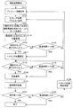
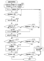
次に、上記写真撮影プリント装置1における処理の流れについて、図3に示すフローチャートを参照しながら説明する。まず、ステップ1(以降、S1のように称する)において、硬貨の投入があるか否かの確認を行う。ここで、利用者による硬貨投入口7から硬貨の投入があることを確認すると(S1においてYES)、次のS2に進む。ここで、硬貨の投入を確認できない場合には(S1においてNO)、硬貨の投入を待つ。すなわち、客待ち状態を維持する。この客待ち状態では、例えば、タッチパネル6モ画面等を表示させておいてもよい。
(Overall process flow)
Next, the flow of processing in the photography printing apparatus 1 will be described with reference to the flowchart shown in FIG. First, in step 1 (hereinafter referred to as S1), it is confirmed whether or not coins are inserted. Here, if it is confirmed that there is a coin inserted from the
S2では、撮影処理が行われる。この撮影処理では、背景シート4の選択や実際の撮影処理などが行われる。ここで、利用者は、画像表示部61に表示されるライブビュー画像を確認しながら、自分の立ち位置やポーズなどを考え、準備が整い次第、撮影開始指示を行うことによって撮影が行われる。この撮影処理については後段で詳細に説明する。
In S2, a photographing process is performed. In this photographing process, selection of the
そして、S3において、S2における撮影開始からの経過時間が設定時間(ここでは、2分)を超えたか否かを判断する。超えていない場合には(S3においてNO)、S2における撮影処理が繰り返し行われる。なお、ここでは、経過時間が2分をオーバーした場合に撮影処理の終了を行う設定になっているが、例えば、撮影枚数が累積限度なった場合や、利用者によって撮影処理の終了指示が出されることにより、撮影処理が終了されるようになっていてもよい。ここで撮影処理によって生成された画像は、記憶装置30に記憶される。
In S3, it is determined whether or not the elapsed time from the start of shooting in S2 exceeds a set time (here, 2 minutes). If not exceeded (NO in S3), the photographing process in S2 is repeated. Note that here, the shooting process is set to end when the elapsed time exceeds 2 minutes. However, for example, when the number of shots reaches the cumulative limit or the user gives an instruction to end the shooting process. In this case, the photographing process may be terminated. Here, the image generated by the photographing process is stored in the
S3において、経過時間が2分を超えたことが確認されると(S3においてYES)、S4に進む。 If it is confirmed in S3 that the elapsed time has exceeded 2 minutes (YES in S3), the process proceeds to S4.
S4では、編集処理が行われる。表示制御部22は、記憶装置30から編集対象となる画像、すなわち撮影処理によって作成された画像(指定範囲の撮影画像)を読み出し、画像表示部61に編集対象となる画像、すなわち撮影処理によって生成された画像が表示される。この画像に対してタッチペン12a.12bを用いて落書きなどの編集処理が行われる。この画像には、例えば、編集処理を行うためのツール類の選択領域が表示されてもよい。ツール類としては、例えば複数の種類からなるペンおよびその色、消しゴム、および複数のスタンプなどが挙げられる。
In S4, an editing process is performed. The
また、編集対象となる画像には、編集対象となる画像を選択するための選択画像が表示されてもよい。利用者は、タッチペン12a・12bによって選択画像をタッチすることによって、中央に編集対象として表示される画像を切り替えることが可能となっていてもよい。なお、この選択画像は、上記の撮影処理において、複数回の撮影が行われた場合の各撮影時における画像に相当するものである。 In addition, a selection image for selecting an image to be edited may be displayed on the image to be edited. The user may be able to switch the image displayed as the editing target in the center by touching the selected image with the touch pens 12a and 12b. Note that this selected image corresponds to an image at the time of each shooting when a plurality of shootings are performed in the above shooting process.
そして、S5において、S4における編集開始からの経過時間が設定時間(ここでは、2分)を超えたか否かを判断する。超えていない場合には(S5においてNO)、S4に戻って編集処理を継続する。なお、ここでは、経過時間が2分をオーバーした場合に撮影処理の終了を行う設定になっているが、例えば、利用者によって編集処理の終了指示が出されることにより、編集処理が終了されるようになっていてもよい。この経過時間がある一定時間になった時点で、まだ編集処理が行われていない選択画像があれば、タッチパネル6に「落書き忘れ」の画像データがある旨の表示を行ってもよい。または、編集処理の時間を、編集処理を行う対象の画像数で割って各画像に与えられた時間とし、各画像に与えられた時間が経過する毎に「次の画像の落書きをしない?」といった催促を画像表示部61に表示させてもよい。上記のような表示により、利用者は、全ての画像に対して、編集処理忘れを防止することができる。また、利用者による編集処理の作業が終了すると、利用者の指示に基づいて、または自動的に、編集処理した各画像をどのような配置で、またどのような分割数で、プリント紙42に印刷するのかが決定されてもよい。
In S5, it is determined whether or not the elapsed time from the start of editing in S4 has exceeded a set time (here, 2 minutes). If not exceeded (NO in S5), the process returns to S4 to continue the editing process. In this example, the shooting process is set to end when the elapsed time exceeds 2 minutes. However, for example, when the user gives an instruction to end the editing process, the editing process is ended. It may be like this. If there is a selected image that has not been subjected to editing processing at the time when this elapsed time reaches a certain time, the
S5において、経過時間が2分を超えたことが確認されると(S5においてYES)、S6に進む。 If it is confirmed in S5 that the elapsed time has exceeded 2 minutes (YES in S5), the process proceeds to S6.
S6では、印刷処理が行われる。S4において編集が施された画像データに基づいた画像を、プリンタ35がプリント紙42に対して出力し、このプリント紙42がプリント排出口9から排出される。
In S6, a printing process is performed. The
以上のシーケンスによって、写真撮影プリント装置1における一連の動作が終了する。 With the above sequence, a series of operations in the photographic printing apparatus 1 is completed.
本実施の形態の写真撮影プリント装置1では、S2の撮影処理において、タッチパネル6における写真の撮影範囲を変更することができる。このことについて以下で、実施例を用いて詳細に説明する。
In the photography printing apparatus 1 of the present embodiment, the photography range of the
(実施例1)
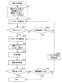
本実施例では、撮影処理における詳細な写真撮影プリント装置1の動作を図4を用いて説明する。
Example 1
In this embodiment, the detailed operation of the photographic printing apparatus 1 in the photographing process will be described with reference to FIG.
撮影処理が開始されると、S111において、タッチパネル6の画像表示部61にプレビュー画像を表示させる。ここで、プレビュー画面とは、写真撮影前のカメラユニット2で撮影されている利用者を含んだ撮影動画像、いわゆるライブビュー画像のことである。なお、ここで、プレビュー画像は、カメラユニット2に撮影されている撮影動画像と、この撮影動画像に対し前影または背景となる装飾用動画像とを合成して、この合成した動画像であってもよい。そして、S112に進む。
When the photographing process is started, a preview image is displayed on the image display unit 61 of the
S112では、表示制御部22は、画像表示部61にトリミング位置を指定するためのトリミング枠をディフォルト位置に表示させる。なお、トリミング位置とは、写真撮影する際に撮影画像(静止画像)が作成される範囲のことである。このトリミング位置を指定する枠をトリミング枠と呼ぶことにする。この画像表示部61に表示されたトリミング枠の例を図5に示す。なお、トリミング枠100の形状および画像表示部61に対する大きさは図5に示したものに限定されない。そしてS113に進む。
In S112, the
S113では、表示制御部22は、画像表示部61に、利用者に対してトリミング位置を決定させるように促すメッセージを表示する。例えば、「操作ボタンを押して好きな撮影範囲を決めてね!」といったメッセージを表示させる。そしてS114に進む。
In S113, the
S114では、利用者によるトリミング位置の変更が行われ、それに応じてトリミング枠100の表示が変更される。利用者は、入力部62からの操作によりトリミング位置の変更を指示し、範囲指定部21はトリミング位置の変更を行う。この変更されトリミング位置の情報を基に表示制御部22は、トリミング枠100をタッチパネル6に表示させる。これらの動作により、利用者は、タッチパネル6上でトリミング枠100を手動で移動することができる。
In S114, the trimming position is changed by the user, and the display of the
トリミング枠100が表示されたタッチパネル6は、例えば、図5に示すようになっていればよい。この図示された例では、利用者は、タッチパネル6上に表示された入力部である操作ボタン(移動ボタン62a)を用いて、トリミング枠100を左右上下に移動させることができるようになっている。なお、図5では、点線で囲まれた四角が移動前のトリミング枠で、実線で囲まれた四角が移動後のトリミング枠100であるとする。
For example, the
また、タッチパネル6上には、トリミング枠100の大きさを変更させることができるサイズ変更のための操作ボタン(サイズ変更ボタン62b)が設けられている。例えば、サイズ変更ボタン62bを押し下す度にトリミング枠100が大きく表示されるようになっていて、トリミング枠100が予め定められた最大サイズになった時点で予め定められた最小サイズに変更されるようになっていればよい。これは、縦、横のどちらか一方の幅はそのままで、他方の幅が大きくなっていくようなサイズ変更であったり(縦長あるいは横長になっていく)、縦横の比は同じままで大きくなっていくようなサイズ変更であったりしてもよい。なお、図5に示す丸の中の数字は、写真撮影までの時間が何秒あるかを示しており、このように、写真撮影までの時間をタッチパネル6上に表示してもよい。
On the
また、操作ボタンが複数設けられていて、これらを用いて複数の利用者がトリミング枠100を移動させたりトリミング枠100のサイズを変更させたりすることができるようになっていてもよい。また、利用者の操作により、トリミング枠の形状を、例えば、縦長、横長、星型、丸型等に変更できるようになっていてもかまわない。
Further, a plurality of operation buttons may be provided, and a plurality of users may be able to move the
S115では、入力部62が、トリミング位置の決定を行う情報を取得したか否かを判定する。つまり、ここでは、利用者によりトリミング位置を決定するための操作ボタンが押し下された否かを判断する。操作ボタンが押し下されたと判断すると(S115においてYES)、S117に進む。操作ボタンが押し下されていないと判断すると(S115においてNO)、S116に進む。
In S115, the
S116では、経過時間が一定時間(ここでは、例えば10秒とする)超えたか否かを判定する。経過時間が10秒を超えていないと(S116においてNO)、S112に戻る。すなわち、本実施例では、10秒の間で、利用者はトリミング位置を決定することができる。S116において、経過時間が10秒を超えたと判断すると(S116においてYES)、S117に進む。 In S116, it is determined whether or not the elapsed time exceeds a certain time (here, for example, 10 seconds). If the elapsed time does not exceed 10 seconds (NO in S116), the process returns to S112. That is, in this embodiment, the user can determine the trimming position within 10 seconds. If it is determined in S116 that the elapsed time has exceeded 10 seconds (YES in S116), the process proceeds to S117.
S117では、範囲指定部21は、S115で利用者が決定したトリミング位置(決定されなかった場合はディフォルトのトリミング位置)を、この時点で画像表示部61に表示されているトリミング枠100の位置に固定する。そしてこの固定したトリミング位置の情報を撮影処理部23に送る。そしてS118に進む。
In S117, the
S118では、入力部62が写真撮影を行うための情報を取得したか否かを判断する。つまり、ここでは、利用者により写真撮影を行うための操作ボタン(撮影ボタン)が押し下された否かを判定する。撮影ボタンが押し下されたと判断した場合には(S118においてYES)、S120の写真撮影に進む。撮影ボタンが押し下されていないと判断した場合には(S118においてNO)、S119に進む。
In S118, it is determined whether the
S119では、トリミング位置が固定されてからの経過時間が一定時間(ここでは、10秒)を超えたか否かを判断する。10秒を超えたと判断すると(S119においてYES)、S120の写真撮影に進む。10秒を超えていないと判断する(S119においてNO)とS118に戻る。すなわち、トリミング位置が固定されてから10秒までの間に写真撮影が開始されるということである。 In S119, it is determined whether or not the elapsed time after the trimming position is fixed exceeds a certain time (here, 10 seconds). If it is determined that it has exceeded 10 seconds (YES in S119), the process proceeds to S120. If it is determined that 10 seconds has not been exceeded (NO in S119), the process returns to S118. That is, photography is started within 10 seconds after the trimming position is fixed.
S120では、カメラユニット2により写真撮影が行われる。この写真撮影では、撮影処理部23は、撮影画像を作成する。その際、トリミング枠100内の画像を撮影画像として作成する。これは、カメラユニット2に映り込んでいる全体画像を撮影してトリミング枠100内の画像を撮影画像として作成すればよい。つまり、ここではデジタルズームを行っていることになる。あるいは、トリミング枠100内の画像を撮影して、これを撮影画像としてもよい。後者のトリミング枠100内の画像を撮影する場合カメラユニット2をトリミング枠100内にズームするように動かす必要があるが、前者のデジタルズームの場合はその必要はない。そのため、デジタルズームの方がカメラユニット2を動かす部材や装置等が必要なく、装置のコスト削減につなげることができる。
In S120, the
S121では、S120で作製した撮影画像を記憶装置30(あるいは外部ディスクドライブ31)に記憶する。そしてS122に進む。 In S121, the captured image created in S120 is stored in the storage device 30 (or the external disk drive 31). Then, the process proceeds to S122.
S122では、撮影画像の記憶装置30における保存数が一定数(ここでは8枚)を超えたか否かを判断する。超えたと判断すると(S122においてYES)撮影処理が終了される。8枚を超えていないと判断する(S122においてNO)とS123に進む。
In S122, it is determined whether or not the number of captured images stored in the
S123では、撮影開始からの経過時間が設定時間(ここでは2分)を超えたか否かを判断する。超えていない場合には(S122においてNO)、S124にてトリミング位置の固定を解除し、S1のプレビュー画面の表示から繰り返される。S123において、経過時間が2分を超えたことが確認されると(S123においてYES)、撮影処理が終了される。なお、ここでは、撮影画像の枚数が8枚になった、あるいは、経過時間が2分をオーバーした場合に撮影処理の終了を行う設定になっているが、例えば、利用者によって撮影処理の終了指示が出されることにより、撮影処理が終了されるようになっていてもよい。 In S123, it is determined whether or not the elapsed time from the start of shooting exceeds a set time (here, 2 minutes). If not exceeded (NO in S122), the fixing of the trimming position is released in S124, and the process is repeated from the display of the preview screen in S1. If it is confirmed in S123 that the elapsed time has exceeded 2 minutes (YES in S123), the photographing process is terminated. Note that, here, the shooting process is set to end when the number of shot images reaches 8 or the elapsed time exceeds 2 minutes. For example, the user ends the shooting process. The imaging process may be terminated when the instruction is issued.
以上のように撮影処理が行われる。なお、本実施例では、トリミング位置を利用者に決定させることができるようになっているが、トリミング位置が予め固定されて変更できないようになっていてもかまわない。すなわち、上述したフローにおいてS113〜S116およびS124がなくてもかまわない。また、このようにトリミング位置が予め固定されている場合等では、表示制御部22が、画像表示部61にトリミング位置を表示させなくても(つまり、S112がなくても)かまわない。
The photographing process is performed as described above. In the present embodiment, the trimming position can be determined by the user, but the trimming position may be fixed in advance and cannot be changed. That is, S113 to S116 and S124 may not be included in the flow described above. In addition, when the trimming position is fixed in advance as described above, the
また、上記S117においてトリミング位置が固定されると、利用者による操作ボタンからのズームイン/ズームアウトの指示により、表示制御部22が、画像表示部61にトリミング枠100内の画像の拡大表示とカメラユニット2が撮影している動画像全体の表示とを交互に行うようになっていてもよい。
When the trimming position is fixed in S117, the
また、例えば、撮影処理が始まる前に利用者に人数を入力させ、分割パターンからトリミング枠のサイズを決定してもよい。これについて図6を用いて説明する。 Further, for example, the user may input the number of people before the photographing process starts, and the size of the trimming frame may be determined from the division pattern. This will be described with reference to FIG.
入力部62が人数の情報を取得すると、表示制御部22は、人数に応じた分割パターンをいくつか画像表示部61に表示させ、利用者に上記分割パターンの中から好みのものを選択させる。そして、表示制御部22は、利用者が選択した分割パターンに合わせたトリミング枠を画像表示部61に表示させる。ここではトリミング枠の表示位置は固定されていてもよいし、利用者が変更できるようになっていてもよい。そして、カメラユニット2により写真撮影が行われ、撮影処理部23が、トリミング枠100内の撮影画像を作成する。そして、編集処理、印刷処理が行われ、上記利用者が選択した分割パターンで分割されたプリント紙が出力される。このような処理により、利用者の好みのパターンの分割数が多い写真プリントを提供することができる。利用者の好みのパターンの分割数が多い写真プリントとは、例えば、図7(a)〜(d)に示すようなものが挙げられる。このような縦長の分割数が多い写真プリントでは、図7(a)に示すように全身が撮影される画像に多く対応することや、図7(b)に示すように、不要な範囲を削った画像に多く対応することができる。また、図7(c)に示すような横長の分割数の多い写真プリントである場合には、被写体の顔のみを撮影する場合に、大人数で並んだ場合にも顔が小さくならずに撮影しプリントすることができる。また、図7(d)に示すように、分割形状が三角や丸になっていると、個性的な形状であるため、写真プリントを手帳等に貼るときに人目を引くことができる。また、編集処理において、余白を利用して楽しい画像を作成することができる。また、トリミング枠100指定の範囲内においては、背景画像を抜き取り(クロマキ処理)、被写体だけを表示させるようにしてもよい。なお、背景については、通常のクロマキ処理用の青色や白色などにしておけばよい。
When the
また、撮影前の画像表示部61に、例えば、枠指定した範囲の画像に対してレンズ効果を付けて部分的に拡大(または縮小)表示させたり、枠内の画像を反転表示させたりするような加工処理が行われた画像が表示されてもよい。これについて、具体的に図8(a)〜(d)を用いて説明する。図8(a)に示すように、画像表示部61に表示された画像の反転を行う範囲(反転範囲)を指定するための操作ボタン(反転範囲指定ボタン62c)、反転範囲内の画像の反転を行うことができる操作ボタン(反転ボタン62d)が設けられている。また、画像表示部61に表示された画像の指定された範囲内の画像に対してレンズ効果を付けることができる範囲(レンズ効果範囲)を指定するための操作ボタン(レンズ効果ボタン)、レンズ効果によって拡大(または縮小)するサイズを決定する操作ボタン(サイズ変更バー62f)が設けられている。
In addition, for example, the image display unit 61 before photographing may be displayed with a lens effect on the image in the range designated by the frame and may be partially enlarged (or reduced) or the image in the frame may be displayed in reverse. An image that has been subjected to various processing processes may be displayed. This will be specifically described with reference to FIGS. As shown in FIG. 8A, an operation button (reverse
利用者がある範囲の画像を反転した場合、タッチペン12a(または12b)を用いて、反転範囲指定ボタン62cをクッリクで指定し、図8(b)に示すように、反転したい範囲をタッチパネル6上で囲むことで反転範囲を指定する。そして、図8(d)に示すように、タッチペン12a(または12b)をタッチパネル6から離すことで、反転範囲が決定される。また、ここでは、例として図8(a)の右の女の子の顔部分が囲まれ反転範囲と決定されたとする。ここでは、四角で囲んでいるが別の形状で囲んでもよい。また、反転範囲を変更したい場合には、図8(d)に示すように、タッチパネル6上の反転範囲内にタッチペン12a(または12b)を接触させて変更したい位置までに動かす(ドラッグする)ことで、反転範囲を変更させることができる。そして、利用者が反転ボタン62dをクリックすることで、反転範囲内の画像が反転される。つまり、図8(a)のように右の女の子の顔部分が反転される。
When the user reverses an image in a certain range, the
このように、画像の加工処理を利用して反転した面白い画像を写真撮影前に、利用者に提供することができる。 In this way, it is possible to provide a user with an interesting image that has been reversed using image processing before taking a picture.
また、利用者がある範囲の画像に対してレンズ効果を付けたい場合、タッチペン12a(または12b)を用いて、レンズ効果ボタン62eをクッリクで指定し、図8(b)に示すように、レンズ効果を付けたい範囲をタッチパネル6上で囲むことでレンズ効果範囲を指定する。そして、図8(d)に示すように、タッチペン12aをタッチパネル6から離すことで、レンズ効果範囲が決定される。ここでは、例として図8(a)の左の女の子の顔部分が囲まれレンズ効果範囲と決定されたとする。ここでは、丸で囲んでいるが別の形状で囲んでもよい。なお、レンズ効果範囲を変更したい場合には、図8(d)に示すように、タッチパネル6上のレンズ効果範囲内にタッチペン12a(または12b)を接触させて変更したい位置までに動かす(ドラッグする)ことで、レンズ効果範囲を変更させることができる。そして、利用者がサイズ変更バー62fを操作することで、レンズ効果範囲内の画像が拡大表示あるいは縮小表示される。なお、図8(a)左の女の子の顔部分は、レンズ効果によって拡大表示されている例である。
When the user wants to add a lens effect to an image in a certain range, the
このようにレンズ効果を付けて部分的に拡大(または縮小)表示させることで、画像に対して魚眼レンズのような歪みを与えることができ、また、歪みを変更することもできる。よって、写真撮影前に、画像の加工処理を利用した面白い画像を利用者に提供することができる。 In this way, by partially enlarging (or reducing) the image with a lens effect, distortion like a fisheye lens can be given to an image, and distortion can be changed. Therefore, it is possible to provide a user with an interesting image using image processing before taking a picture.
なお、上記の表示における加工処理は表示制御部22が行うものとするが、別の処理部が行ってもよい。
In addition, although the
上記のように、指定範囲を枠により決めて、その枠内の画像に施す加工処理は、反転処理や、レンズ効果を付けたりするものに限定されず、その他の画像処理であってもてもよい。 As described above, the specified range is determined by the frame, and the processing performed on the image within the frame is not limited to the reversal process or the lens effect, but may be other image processes. Good.
また、撮影前に加工処理された画像の表示に関する別の例について図9を用いて説明する。図9(a)に示すように、所定の範囲が指定され、この範囲に含まれる顔を認識することで、被写体同士の顔全体を入れ替えて表示するようになっていてもよい。顔の認識は、例えば、鼻とそれを挟む目を検出することで1人の顔と認識すればよい。所定の範囲内であれば、被写体が移動しても顔を認識できるようになっていればよい。このような顔の認識方法は単なる例示であり、認識方法はこれに限定はされない。ここでは、2人の顔を認識し、互いに入れ替えて表示しているが、例えば、3人以上の顔を認識しランダムに入れ替えてもよい。また、図9(b)に示すように、所定の範囲が指定され、範囲内における目を入れ替えて表示できるようになっていてもよい。この場合、目の認識は、例えば、鼻筋とそれを挟む目を検出することで、1人の顔における目であると認識すればよい。所定の範囲内であれば、被写体が移動しても目を認識できるようになっていればよい。このような目の認識方法は単なる例示であり、認識方法はこれに限定はされない。ここでは、2人の目を認識し、互いに入れ替えて表示しているが、例えば、3人以上の目を認識しランダムに入れ替えてもよい。また、図9(c)に示すように、所定の範囲が指定され、この範囲に含まれる顔を認識することで、認識した顔の右半分を顔の左半分に当たる部分に反転表示させてもよい。あるいは、左半分の顔が右半分に当たる部分に反転表示させてもよい。つまり、鼻筋を中心に左右対称の顔が表示されることになる。顔の認識方法は、上記したものと一緒であってもよい。なお、上記の表示における加工処理も表示制御部22が行うものとするが、別の処理部がおこなってもよい。
Another example relating to the display of an image processed before photographing will be described with reference to FIG. As shown in FIG. 9A, a predetermined range may be designated, and the faces included in this range may be recognized so that the entire faces of the subjects are switched and displayed. For example, the face may be recognized as one person's face by detecting the nose and the eyes sandwiching it. If it is within a predetermined range, it is sufficient that the face can be recognized even if the subject moves. Such a face recognition method is merely an example, and the recognition method is not limited thereto. Here, the faces of two people are recognized and replaced with each other, but, for example, three or more faces may be recognized and replaced at random. Further, as shown in FIG. 9B, a predetermined range may be designated, and the eyes within the range may be exchanged and displayed. In this case, the recognition of the eyes may be recognized as an eye on one face by detecting, for example, the nose and the eyes sandwiching the nose. If it is within a predetermined range, it is only necessary to be able to recognize eyes even if the subject moves. Such an eye recognition method is merely an example, and the recognition method is not limited thereto. Here, the eyes of two people are recognized and switched to each other, but for example, the eyes of three or more people may be recognized and switched at random. In addition, as shown in FIG. 9C, a predetermined range is specified, and by recognizing a face included in this range, the right half of the recognized face can be highlighted and displayed on the portion corresponding to the left half of the face. Good. Alternatively, the left half face may be highlighted on the right half. That is, a symmetrical face is displayed around the nose. The face recognition method may be the same as described above. In addition, although the
また、図8,9を用いて説明した上記撮影前の加工処理は単なる例示であり、上記に限定はされない。 Further, the processing before photographing described with reference to FIGS. 8 and 9 is merely an example, and is not limited to the above.
(実施例2)
本実施例では、撮影処理における詳細な写真撮影プリント装置1の動作を図10を用いて説明する。
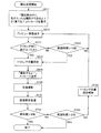
(Example 2)
In this embodiment, the detailed operation of the photographic printing apparatus 1 in the photographing process will be described with reference to FIG.
撮影処理が開始されると、S211において、タッチパネル6の画像表示部61にプレビュー画像を表示する。なお、ここで、プレビュー画像は、カメラユニット2に撮影されている撮影動画像と、この撮影動画像に対し前影景または背景となる装飾用動画像とを合成して、この合成した動画像であってもよい。そして、S212に進む。
When the photographing process is started, a preview image is displayed on the image display unit 61 of the
S212では、表示制御部22は、画像表示部61にトリミング位置を指定するためのトリミング枠100をディフォルト位置に表示させる。そしてS213に進む。
In S212, the
S213では、トリミング枠100の表示からの経過時間が一定時間(ここでは1秒)を超えたか否かを判定する。1秒を超えていると判断すると(S213においてYES)、S214に進む。超えていないと判断すると(S213においてNO)、S212に戻る。つまり、トリミング枠100をディフォルト位置に表示させておくのは、ここでは1秒間ということである。
In S213, it is determined whether or not the elapsed time from the display of the
S214では、トリミング位置移動処理が行われる。この処理について図11を用いて説明する。処理が開始されると、S31において、乱数シードの決定が行われ、S32に進む。 In S214, a trimming position moving process is performed. This process will be described with reference to FIG. When the process is started, a random number seed is determined in S31, and the process proceeds to S32.
S32では、画像表示部61におけるトリミング枠100を表示させるトリミング表示位置を決定する。ここでは、具体的にトリミング表示位置が画像表示部61上に8カ所存在する場合について説明する。式
変数[トリミング表示位置]=int(rnd()*8.0)+1
(ここで、
「int()」は、()内の少数を整数にする処理を意味し、
「rnd()」は、0〜1.0未満の一様乱数(小数値)を発生させる処理を意味する)
に基づき、トリミング表示位置を決定する。そしてS33に進む。
In S32, a trimming display position for displaying the
(here,
“Int ()” means a process of converting a decimal number in () to an integer,
“Rnd ()” means a process of generating a uniform random number (decimal value) of 0 to less than 1.0.
Based on the above, the trimming display position is determined. Then, the process proceeds to S33.
S33では、S32で変数[トリミング表示位置]で決定された位置にトリミング枠100を表示させる。つまり、ディフォルト位置から上記決定された位置にトリミング表示位置変更させる。このようにトリミング位置移動処理を行うことにより、図12に示すように、トリミング枠100が表示位置のうちのいずれかに表示される。なお、図12では、点線で囲まれた四角がトリミング表示位置で、実線で囲まれた四角が表示されたトリミング枠100である。
In S33, the
また、図13のフローチャートに示すような別のトリミング位置移動処理が行われてもよい。ここで、乱数シードの決定からトリミング位置を表示するまで(S31〜S33)は、上記で図11を用いて説明したフローと同じであるので同じステップ番号を付記し、説明は省略する。 Further, another trimming position movement process as shown in the flowchart of FIG. 13 may be performed. Here, since the flow from the determination of the random number seed to the display of the trimming position (S31 to S33) is the same as the flow described above with reference to FIG. 11, the same step number is added and the description is omitted.
S33で、表示制御部22が画像表示部61にトリミング枠100を表示したら、S34に進む。
When the
S34では、ズームイン中か否か、つまり、トリミング枠100内の画像が拡大表示されているか否かを判断する。ズームイン中であると判断すると(S34においてYES)、S35に進み、ズームアウト処理をする。つまり、トリミング枠100内の拡大表示から、カメラユニット2が撮影している全体を表示する全体表示に戻す。
In S34, it is determined whether or not the zoom-in is being performed, that is, whether or not the image in the
S34において、ズームイン中でないと判断すると(S34においてNO)S36に進み、ズームイン処理する。すなわち、トリミング枠100内の画像を画像表示部61に拡大表示する。画像表示部61における画像の例を図14(a),(b)に示す。図14(a)がズームアウト処理した場合の表示例であり、同図(b)がズームイン処理した場合の表示例である。
If it is determined in S34 that zoom-in is not in progress (NO in S34), the process proceeds to S36 to perform zoom-in processing. That is, the image within the
上記のような、トリミング位置移動処理を図14に示すようにS214で行い、S215に進む。なお、上記で説明したトリミング位置移動処理は例示であり、処理方法は、これらに限定されない。 The trimming position moving process as described above is performed in S214 as shown in FIG. 14, and the process proceeds to S215. The trimming position movement process described above is an example, and the processing method is not limited to these.
S215では、トリミング位置移動処理が開始されてからの経過時間が一定時間(ここでは10秒)を超えたか否かを判断する。10秒を超えたと判断すると(S215においてYES)、S216に進む。超えていないと判断すると(S215においてNO)、S214に戻り、トリミング位置移動処理が繰り返される。つまり、10秒の間、トリミング枠100が乱数によって表示位置を変えて表示される。あるいは、トリミング枠100が乱数によって表示位置を変えて表示され枠内のズームインまたはズームアウトが行われる。上記では、乱数を用いて、つまり利用者からみれば不規則にトリミング枠100の表示が行われるが、例えば、所定の数の表示位置に規則的に順番にトリミング枠100が表示されるようになっていてもよい。
In S215, it is determined whether or not the elapsed time since the trimming position moving process has started exceeds a certain time (here, 10 seconds). If it is determined that 10 seconds have been exceeded (YES in S215), the process proceeds to S216. If it is determined that it has not exceeded (NO in S215), the process returns to S214, and the trimming position movement process is repeated. That is, for 10 seconds, the
S216では、トリミング位置が固定される。範囲指定部21は、トリミング位置を、トリミング位置移動処理が開始されてから10秒経過した時点で画像表示部61に表示されているトリミング枠100の位置に固定する。そしてこの固定したトリミング位置の情報を撮影処理部23に送る。そしてS120に進む。
In S216, the trimming position is fixed. The
S120では、写真撮影が行われる。本実施例では、トリミング位置が固定されると写真撮影が開始される。そのため、ランダムに動くトリミング枠100が最終的にどの位置にくるか利用者には分からないため、予想外の位置での写真撮影が行われることになる。そのため、利用者は、単に撮影するだけでなく、楽しみながら撮影することができる。
In S120, a photograph is taken. In the present embodiment, photography is started when the trimming position is fixed. Therefore, since the user does not know where the
本実施例では、S120〜S123での処理は、実施例1で図4を用いて説明した処理と同じであるので、同じステップ番号を付け説明を省略する。 In the present embodiment, the processing in S120 to S123 is the same as the processing described in Embodiment 1 with reference to FIG.
(実施例3)
本実施例では、撮影処理における詳細な写真撮影プリント装置1の動作を図15を用いて説明する。本実施例では、ゲームを用いてトリミング位置を決定する。
(Example 3)
In this embodiment, the detailed operation of the photographic printing apparatus 1 in the photographing process will be described with reference to FIG. In this embodiment, the trimming position is determined using a game.
撮影処理が開始されると、S311において、表示制御部22は、画像表示部61にゲームの説明のための、例えば「決定ボタンが現れたら、お友達より早く押そう!」といった、メッセージを表示する。そしてS312に進む。
When the photographing process is started, in S311, the
S312では、タッチパネル6の画像表示部61にプレビュー画像を表示する。本実施例ではここで、プレビュー画面と共に、トリミング枠100を2つそれぞれディフォルト位置に表示する。この2つのトリミング枠100は、識別できるように色が異なっているのが好ましい。そして、S313に進む。
In S312, a preview image is displayed on the image display unit 61 of the
S313では、トリミング枠100の表示からの経過時間が一定時間(ここでは5秒)を超えたか否かを判定する。5秒を超えていると判断すると(S313においてYES)、S314に進む。超えていないと判断すると(S313においてNO)、S312に戻る。つまり、5秒間トリミング枠100が表示される。本実施例では、図16に示すように、タッチパネル6上で例えば2人の利用者がトリミング枠100を移動できるように、また、トリミング枠100のサイズを変更できるようになっている。入力部62である移動ボタン62aの色とサイズ変更ボタン62bの色とを、ディフォルト枠の色と合わせておくと、利用者は、2つある入力部62のうちどちらが、どちらのディフォルト枠に対応しているか判断しやすいため好ましい。図16では、点線で囲まれた四角が右の操作ボタンで操作できるトリミング枠100で、実線で囲まれた四角が左の操作ボタンで操作できるトリミング枠100であるとする。上記5秒間に利用者は、それぞれ自分の好みの位置にトリミング枠100を移動させたり、好みのサイズにトリミング枠100を変更させたりする。
In S313, it is determined whether or not the elapsed time from the display of the
S314では、表示制御部22は、タッチパネル6上にトリミング枠100の位置を決定するための操作ボタンである決定ボタンを2つ表示させる。この表示位置は特に限定されないが、例えば、2つあるサイズ変更ボタン62b付近であると、サイズ変更ボタン62bや移動ボタン61aを操作していた利用者は操作しやすい。また、この決定ボタンもディフォルト枠の色と合わせておいてもよい。そして、S315に進む。なお、ここでは、決定ボタンを表示させて利用者の操作に供するようにしたが、入力部62としての決定ボタンが初めからタッチパネル6上に表示されており、このS314で、使用を可能、つまり、入力部が入力を受け付けるようになっていてもよい。
In S <b> 314, the
S315では、利用者により決定ボタンが押し下された否かを判定する。決定ボタンが押し下されたと判断した場合には(S315においてYES)、S317に進む。ここで、入力部62は、2つの決定ボタンのうち先に押し下された方のボタンからの入力を受け付ける。つまり、本実施例では、利用者2人のうち、決定ボタンを早く押した方のトリミング枠100が撮影に用いられるというゲーム性を持たせている。
決定ボタンが押し下されていないと判断した場合には(S315においてNO)、S316に進む。
In S315, it is determined whether or not the user presses the enter button. If it is determined that the enter button has been pressed (YES in S315), the process proceeds to S317. Here, the
If it is determined that the enter button has not been pressed (NO in S315), the process proceeds to S316.
S316では、プレビュー画面表示の開始からの経過時間が一定時間(ここでは10秒)を超えたか否かを判定する。10秒を超えていると判断すると(S316においてYES)、S317に進む。超えていないと判断すると(S316においてNO)、S312に戻る。 In S316, it is determined whether or not the elapsed time from the start of the preview screen display has exceeded a certain time (here, 10 seconds). If it is determined that it has exceeded 10 seconds (YES in S316), the process proceeds to S317. If it is determined that it has not exceeded (NO in S316), the process returns to S312.
S317では、トリミング位置の固定が行われる。範囲指定部21は、トリミング位置を、利用者により決定ボタンの操作により決定された方のトリミング枠100の表示位置に固定する。決定ボタンが押し下されていない場合は、トリミング位置をディフォルト位置に固定する。そして、どちらの場合でも、固定したトリミング位置の情報を撮影処理部23に送り、S318に進む。
In S317, the trimming position is fixed. The
S318では、決定ボタンをタッチパネル6上において非表示とする。あるいは、半透明表示とし、タッチパネル6上の決定ボタンの使用を不可能に、つまり決定ボタンからの入力を受け付けないようにしてもよい。そしてS118に進む。
In S318, the determination button is not displayed on the
本実施例では、以下S118〜S124での処理は、実施例1で図4を用いて説明した処理と同じであるので、同じステップ番号を付け、説明を省略する。 In the present embodiment, the processes in S118 to S124 are the same as those described with reference to FIG. 4 in the first embodiment, and therefore the same step numbers are assigned and description thereof is omitted.
本実施例では、対戦型のゲームとして撮影が進行されるため、単なる写真撮影だけでなく、新たは遊びを付け加えることができる。なお、上記したゲームの内容は、単なる例示であって、上記したものに限定されない。 In this embodiment, since shooting is performed as a battle-type game, not only mere photography but also new play can be added. The contents of the game described above are merely examples, and are not limited to those described above.
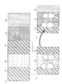
本実施例において、画像表示部61に背景画像が表示されており、被写体が移動するのが検知されると、それに合わせて画像表示部61に表示された背景画像も移動するようになっていてもよい。例えば、図17に示すように、画像表示部61に表示される背景画像を、画像表示部61に表示される範囲より左右に大きな画像として記憶装置30に記憶しておく。被写体が画像表示部61に対して右側に動いたのを検知すると、表示制御部22は、記憶装置30から、背景画像のうち画像表示部61に表示されていない右側の背景を読み出し、左側に動くように表示する。つまり、被写体が移動する前、図17(b)に示すように、背景B1〜B3が画像表示部61に表示されているとする。なおここでは、背景画像は、図17(a)に示すように、背景B1〜B5まで連続しているものとする。被写体が図面右方向に移動すると、背景画像は図面左方向に移動し、図17(c)に示すように被写体の後ろには背景B3〜B5が表示される。このとき、被写体の動きに比して背景画像を大きく動かせて表示すると、利用者は、ほんの少し移動するだけで、好みの背景を得ることができる。また、撮影空間5を大きく移動しているように感じることができる。なお、このような、背景画像の動きは単なる例示であり、これに限定されることはない。
In this embodiment, a background image is displayed on the image display unit 61. When it is detected that the subject moves, the background image displayed on the image display unit 61 moves accordingly. Also good. For example, as illustrated in FIG. 17, the background image displayed on the image display unit 61 is stored in the
また、被写体の顔部分をプリントアウト用の写真撮影の先に別撮影しておき、ライブビュー画像の表示時に、上記別撮影の顔部分(顔画像と呼ぶ)を画像表示部61に貼り付けて表示し、これを写真撮影できるようになっていてもよい。例えば、図18(a)に示すように、画像表示部61に表示された全体画像が写真撮影され、画像表示部61に撮影画像(静止画像)が表示される。そして、利用者は、この静止画像に対し、図18(b)に示すようにタッチペン12a(あるいは12b)を用いて顔範囲を囲む。これにより、顔画像を指定することができる。そして、図18(c)に示すように、タッチパネル6からタッチペン12aを離すと、顔画像として用いる範囲を決定することができる。
Also, the face portion of the subject is taken separately before the printout photography, and the face portion (referred to as a face image) of the above-mentioned separate photographing is pasted on the image display unit 61 when the live view image is displayed. It may be possible to display and take a picture. For example, as shown in FIG. 18A, the entire image displayed on the image display unit 61 is photographed, and the photographed image (still image) is displayed on the image display unit 61. Then, the user surrounds the face range with the
その後、例えば、図18(e)に示すように、顔画像の不要部分を消すような加工を加え、図18(f)に示すような加工された顔画像が記憶装置30に記憶される。そして、例えば図19に示すように、表示制御部22は、記憶装置30に記憶した顔画像を読み出して、ライブビュー画像に重ねて表示させる。顔画像を表示させるか否かは、利用者が決定できるようになっていればよい。また、利用者が画像表示部61において、この顔画像の表示位置を移動したり、サイズ変更したりできるようになっていてもよい。このように、顔画像を加えることで、単なる写真撮影とは違った楽しみを利用者に与えることができる。
Thereafter, for example, as shown in FIG. 18E, a process for erasing unnecessary portions of the face image is added, and the processed face image as shown in FIG. 18F is stored in the
また、上記顔画像を用いる場合、次のようなことも考えられる。図20(a)に示すように、画像表示部61上に顔画像を不規則に移動させて表示させる。そうすると顔画像が表示される部分には、被写体は写ることができないため、利用者は、顔画像を避けるように移動し、そして写真撮影が行われる。このように、単なる写真撮影とは違った楽しみを利用者に与えることができる。また、普段とは違った表示を撮影することができる。 Further, when the face image is used, the following may be considered. As shown in FIG. 20A, the face image is irregularly moved and displayed on the image display unit 61. Then, since the subject cannot appear in the portion where the face image is displayed, the user moves so as to avoid the face image, and the photograph is taken. In this way, it is possible to give the user a different kind of fun from photography. In addition, it is possible to shoot a display different from usual.
あるいは、画像表示部61に、顔画像を不規則に移動させて表示させる代わりに流れ星が降るように星を表示させてもよい。利用者は、星を避けるようにしながら、写真撮影が行われるため、楽しみながら撮影することができる。 Alternatively, a star may be displayed on the image display unit 61 so that a shooting star falls instead of displaying the face image irregularly. The user can take pictures while having fun because photography is performed while avoiding stars.
(実施例4)
本実施例では、撮影処理における詳細な写真撮影プリント装置1の動作を図21を用いて説明する。本実施例では、猫を捕まえるゲームを用いてトリミング位置を決定する。本実施例では、猫を捕まえるゲームの情報が、画像表示部における範囲を指定するための範囲指定情報である。
Example 4
In this embodiment, the detailed operation of the photographic printing apparatus 1 in the photographing process will be described with reference to FIG. In this embodiment, the trimming position is determined using a game for catching cats. In the present embodiment, game information for catching a cat is range designation information for designating a range in the image display unit.
撮影処理が開始されると、S411において、表示制御部22は、画像表示部61にゲームの説明のための、例えば「操作ボタンを使って、猫を捕まえよう!」といった、メッセージを表示する。そしてS412に進む。
When the shooting process is started, in S411, the
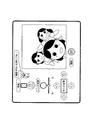
S412では、タッチパネル6の画像表示部61にプレビュー画像を表示する。本実施例ではここで、プレビュー画面と共に、猫の画像と猫を捕まえるための捕獲網の画像とをディフォルト位置に表示する。そして、猫を画像表示部61上にランダムに移動させて表示し、S413に進む。本実施例では、例えば図22(a)に示すように、タッチパネル6上で利用者が捕獲網を上下左右に移動することができる操作ボタン(網移動ボタン62g)と、捕獲網を下す操作ができる操作ボタン(網おろしボタン62h)とが、設けられている。入力部62としてこれらの操作ボタンを用いて、利用者は、画像表示部61上の捕獲網を操作し、図22(b)に示すように、画像表示部61上で猫を捕まえることができる。
In step S412, a preview image is displayed on the image display unit 61 of the
S413では、利用者が捕獲網を操作し、猫を捕まえたか否かを判断する。猫を捕まえたと判断すると(S413においてYES)、S415に進む。猫を捕まえていないと判断すると(S413においてNO)、S414に進む。 In S413, it is determined whether the user has operated the capture net and has caught a cat. If it is determined that the cat has been caught (YES in S413), the process proceeds to S415. If it is determined that the cat is not caught (NO in S413), the process proceeds to S414.
S414では、プレビュー画面表示の開始からの経過時間が一定時間(ここでは10秒)を超えたか否かを判定する。10秒を超えていると判断すると(S414においてYES)、S415に進む。超えていないと判断すると(S414においてNO)、S412に戻る。つまり、利用者は、最大10秒の間、網移動ボタン62gと網おろしボタン62hとを用いて猫を捕まえる操作を行うことができる。
In S414, it is determined whether or not the elapsed time from the start of the preview screen display has exceeded a certain time (here, 10 seconds). If it is determined that it has exceeded 10 seconds (YES in S414), the process proceeds to S415. If it is determined that it has not exceeded (NO in S414), the process returns to S412. That is, the user can perform an operation of catching the cat using the net moving
S415では、トリミング位置の固定が行われる。表示制御部22は、画像表示部61において、猫を捕まえた位置を中心に所定の大きさの範囲にトリミング枠100を表示させる。範囲指定部21は、このトリミング枠100が表示された範囲をトリミング位置として固定するとする。利用者が猫を捕まえていない場合は、表示制御部22は、画像表示部61において、ディフォルト位置にトリミング枠100を表示させる。この場合は、範囲指定部21は、トリミング位置をディフォルト位置に固定する。そして、どちらの場合でも、固定したトリミング位置の情報を撮影処理部23に送り、S416に進む。
In S415, the trimming position is fixed. The
S416では、表示制御部22は、画像表示部61に「撮影を開始するよ!」等の写真撮影が始まることを知らせるメッセージを表示させる。
In S <b> 416, the
本実施例では、以下S120〜S124での処理は、実施例1で図4を用いて説明した処理と同じであるので、同じステップ番号を付け説明を省略する。 In the present embodiment, the processing in S120 to S124 is the same as the processing described in Embodiment 1 with reference to FIG.
なお、上記では、捕獲網を使って猫を捕まえ、その位置にトリミング枠100を表示させるものとしたが、これに限定されることはない。例えば、S412においてプレビュー画面と共に猫の画像とトリミング枠100とを表示させ、利用者はこのトリミング枠100内に猫が入る様に操作(トリミング枠100で猫を捕まえる)し、その猫を捕まえたトリミング枠100が表示されている位置をトリミング位置としてもよい。
In the above description, the cat is caught using the catch net and the
本実施例では、捕獲網で猫を捕まえるといったゲームを通して撮影が進行されるため、単なる写真撮影だけでなく、新たな遊びを付け加えることができる。なお、上記したゲームの内容は単なる例示であって、ゲー内容は上記したものに限定されない。 In this embodiment, since shooting is performed through a game of catching a cat with a catching net, it is possible to add not only photography but also new play. The contents of the game described above are merely examples, and the game contents are not limited to those described above.
(実施例5)
本実施例では、撮影処理における詳細な写真撮影プリント装置1の動作を図23を用いて説明する。本実施例では、鳥がトリミング枠100内に入るとそのトリミング位置で撮影開始する。本実施例では、鳥とトリミング枠100の情報が、画像表示部における範囲を指定するための範囲指定情報である。
(Example 5)
In this embodiment, the detailed operation of the photographic printing apparatus 1 in the photographing process will be described with reference to FIG. In this embodiment, when a bird enters the
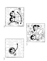
撮影処理が開始されると、S511において、表示制御部22は、画像表示部61に写真撮影の説明のための、例えば「撮影枠の中に鳥が入ったら撮影ができるよ!よく見ててね!」といった、メッセージを表示する。そしてS512に進む。
When the photographing process is started, in S511, the
S512では、タッチパネル6の画像表示部61にプレビュー画像を表示する。本実施例ではここで、プレビュー画面と共に、トリミング枠100と鳥の画像とをディフォルト位置に表示する。この表示は、例えば、図24(a)のようになっていればよい。このように、鳥のディフォルト位置はトリミング枠100外とする。そして、鳥とトリミング枠100とをそれぞれ、画像表示部61上にランダムに移動させて表示し、S513に進む。
In S512, a preview image is displayed on the image display unit 61 of the
S513では、トリミング枠100に鳥が入った否かを判断する。例えば、画像表示部61において図24(b)に示すような表示が行われると、トリミング枠100に鳥が入ったと判断し(S513においてYES)、S515に進む。トリミング枠100に鳥が入っていないと判断すると(S513においてNO)、S514に進む。
In S513, it is determined whether or not a bird has entered the
S514では、プレビュー画面表示の開始からの経過時間が一定時間(ここでは10秒)を超えたか否かを判定する。10秒を超えていると判断すると(S514においてYES)、S515に進む。超えていないと判断すると(S514においてNO)、S512に戻る。つまり、鳥がトリミング枠100内に入らない限り、最長10秒間、トリミング枠100と鳥とが画像表示部61上を動きまわる。
In S514, it is determined whether or not the elapsed time from the start of the preview screen display exceeds a certain time (here, 10 seconds). If it is determined that it has exceeded 10 seconds (YES in S514), the process proceeds to S515. If it is determined that it has not exceeded (NO in S514), the process returns to S512. That is, unless the bird enters the
S515では、トリミング位置の固定が行われる。範囲指定部21は、トリミング位置を、鳥が枠内に入った時点で表示されているトリミング枠100の表示位置に固定する。鳥がトリミング枠100内に入っていない場合は、トリミング位置をディフォルト位置に固定する。そして、どちらの場合でも、固定したトリミング位置の情報を撮影処理部23に送り、S516に進む。
In S515, the trimming position is fixed. The
S516では、表示制御部22は、画像表示部61に「撮影を開始するよ!」等の写真撮影が始まることを知らせるメッセージを表示させ、写真撮影開始までのカウントダウンを行う。そしてS120に進む。
In S516, the
S120では、写真撮影が行われる。この場合、撮影処理部23は、トリミング枠100内を撮影画像として作成するが、トリミング枠100内の鳥を含んだ画像を撮影画像として作成してもよい。
In S120, a photograph is taken. In this case, the photographing
本実施例では、S120〜124の処理は、実施例1で図4を用いて説明した処理と同じであるので、同じステップ番号を付け説明を省略する。 In the present embodiment, the processing of S120 to S124 is the same as the processing described in Embodiment 1 with reference to FIG.
本実施例では、鳥がトリミング枠100に入ることで、撮影開始の合図となり、写真撮影が開始される。よって、従来のカウントダウンとは異なった撮影タイミングを提供することができる。そのため、利用者は、何時写真撮影が行われるかが予想できず、意外なタイミングで撮影することができ、単に撮影するだけでなく、楽しみながら撮影することができる。なお、上記した鳥とトリミング枠100とを用いた撮影開始の合図は単なる例示であって、上記したものに限定されない。
In this embodiment, when a bird enters the
(実施例6)
本実施例では、撮影処理における詳細な写真撮影プリント装置1の動作を図25を用いて説明する。本実施例では、トリミング枠100内に登録した人数が全て入った時点で撮影開始する。
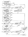
(Example 6)
In this embodiment, the detailed operation of the photographic printing apparatus 1 in the photographing process will be described with reference to FIG. In the present embodiment, the photographing is started when all the registered persons are entered in the
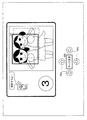
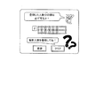
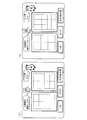
撮影処理が開始されると、S611において、表示制御部22は、画像表示部61に、被写体の人数を入力させるための、例えば「撮影人数を登録してね!」といった、メッセージを表示する。そして、画像表示部61に、例えば、図26のように利用者に人数を入力させるための入力部62である入力画面を表示する。そしてS612に進む。利用者は、入力画面から数、つまり、撮影人数を登録することができる。ここで、撮影人数を登録することにより、後の編集処理において、どのような分割数で、プリント紙42に印刷するのかを決定する際に、図27(a),(b)に示すように、登録した人数に応じた分割数を提示させることもできる。利用者は、登録人数に応じて提示された分割数の表示の中から好きなレイアウトを選択することができる。つまり、ここで、3人と登録した場合には、編集処理における分割数の選択では、図27(b)に示す画像が提示されることになる。
When the photographing process is started, in S611, the
S612では、利用者により人数が入力されたか否かを判断する。人数が入力されたと判断すると(S612においてYES)、S615に進む。人数が入力されていないと判断すると(S612においてNO)、S613に進む。 In S612, it is determined whether or not the number of users has been input by the user. If it is determined that the number of persons has been input (YES in S612), the process proceeds to S615. If it is determined that the number of persons has not been input (NO in S612), the process proceeds to S613.
S613では、入力画面の表示開始からの経過時間が一定時間(ここでは10秒)を超えたか否かを判定する。10秒を超えていると判断すると(S613においてYES)、S614に進む。S614では、人数認識手段は、ディフォルト値(ここでは3)を登録人数として格納する。そして、S616に進む。S613で、10秒を超えていないと判断すると(S613においてNO)、S611に戻る。つまり、入力画面が表示されるのは10秒である。 In S613, it is determined whether or not the elapsed time from the start of display of the input screen exceeds a certain time (here, 10 seconds). If it is determined that it has exceeded 10 seconds (YES in S613), the process proceeds to S614. In S614, the number-of-persons recognition means stores a default value (here, 3) as the registered number. Then, the process proceeds to S616. If it is determined in S613 that 10 seconds has not been exceeded (NO in S613), the process returns to S611. That is, the input screen is displayed for 10 seconds.
S615では、人数認識部24は、利用者により入力された人数(入力値)を登録人数と格納する。そしてS616に進む。
In S615, the number of
S616では、タッチパネル6の画像表示部61にプレビュー画像が表示される。そしてS617に進む。
In S616, a preview image is displayed on the image display unit 61 of the
S617では、トリミング枠100を画像表示部61におけるディフォルト位置に表示させる。そして、S618に進む。なお、ここで、トリミング枠100を利用者が移動させたり、サイズ変更させたりできるようになっていてもよい。
In S617, the
S618では、表示制御部22は、画像表示部61に「撮影を開始するよ!」等の写真撮影が始まることを知らせるメッセージを表示させる。そしてS619に進む。
In S <b> 618, the
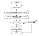
S619では、人数検知処理が行われる。この人数検知処理の例について図28を用いて説明する。 In S619, a number detection process is performed. An example of this number detection process will be described with reference to FIG.
人数検知処理が開始されると、S41において、顔認識処理が行われる。ここで、顔認識処理とは、画像表示部61のトリミング枠100内に写っている被写体の顔の数を検知する処理のことであり、例えば、鼻とこれを挟んだ目とこれらを囲む輪郭とを認識することで、1人の顔であると認識するようになっていればよい。表示制御部22は、顔認識処理を行い顔の数を検知すると、S42に進む。ここでは、表示制御部22が顔認識処理を行っているが別の処理部が行ってもよい。
When the number detection process is started, a face recognition process is performed in S41. Here, the face recognition process is a process of detecting the number of faces of the subject in the
S42では、人数認識部24は、表示制御部がS41で検知した顔の数を検知人数として格納する。そして、S43に進む。
In S42, the number of
S43では、人数認識部24は、S614あるいはS615で格納した登録人数と検知人数とが等しいが否かを判断する。換言すれば、トリミング枠100内に、上記登録人数と同じ数の被写体が入っているか否かを判断するということである。登録人数と検知人数とが等しい場合(S43においてYES)、S44に進む。S44では、撮影フラグをオンにする。
In S43, the number of
S43において、登録人数と検知人数とが等しくない場合には(S43においてNO)、S45に進む。S45では、撮影フラグをオフにし、S46に進む。 In S43, when the registered number of people and the detected number of people are not equal (NO in S43), the process proceeds to S45. In S45, the shooting flag is turned off, and the process proceeds to S46.
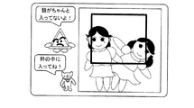
S46では、人数認識部24が、人数を検知できなかった場合には、「ちゃんと写らない人がいるよ」等の、トリミング枠100内に全員の顔が入っていないことを警告するメッセージを画像表示部61に表示させる。これは、例えば図29に示すような表示であってもよい。なお、この警告は、例えば、スピーカからの音声出力であってもよい。
In S46, when the number of
このように本実施例では、トリミング枠100内に登録人数と同じ数の顔を確認することができれば、撮影条件が整うということである。本実施例では、以上のように人数検知処理が行われるが、処理方法は、これに限定されることはない。人数検知処理が終われば、図25に示すS620に進む。
As described above, in this embodiment, if the same number of faces as the number of registered persons can be confirmed in the
S620では、撮影フラグがオンになっているか否かが判断される。つまり、写真撮影できる準備が整っているか否かが判断される。撮影フラグがオンになっていると判断すると(S620においてYES)、S120に進む。撮影フラグがオンになっていないと判断すると(S620においてNO)、S621に進む。 In S620, it is determined whether or not the shooting flag is on. That is, it is determined whether or not preparation for taking a photograph is ready. If it is determined that the shooting flag is on (YES in S620), the process proceeds to S120. If it is determined that the shooting flag is not turned on (NO in S620), the process proceeds to S621.
S621では、人数検知処理開始からの経過時間が一定時間(ここでは15秒)を超えたか否かを判定する。15秒を超えていると判断すると(S621においてYES)、S120に進む。10秒を超えていないと判断すると(S621においてNO)、S619に戻り人数検知処理が繰り返される。 In S621, it is determined whether or not the elapsed time from the start of the number of people detection process exceeds a certain time (here, 15 seconds). If it is determined that it has exceeded 15 seconds (YES in S621), the process proceeds to S120. If it is determined that 10 seconds has not been exceeded (NO in S621), the process returns to S619 and the number of people detection process is repeated.
本実施例では、以下S120〜S124での処理は、実施例1で図4を用いて説明した処理と同じであるので、同じステップ番号を付け説明を省略する。本実施例では、登録した数の顔を欠かすことなく撮影することができる。 In the present embodiment, the processing in S120 to S124 is the same as the processing described in Embodiment 1 with reference to FIG. In this embodiment, it is possible to shoot without missing the registered number of faces.
以上実施例1〜7で説明した撮影処理は、単なる例示であり、上記されたものに限定されず、例えば、ゲームが適宜組み合わさっていてもよい。 The shooting processes described in the first to seventh embodiments are merely examples, and are not limited to those described above. For example, a game may be combined as appropriate.
なお、上記実施形態の写真撮影プリント装置1の各部や各処理ステップは、CPU(Central Processing Unit)などの演算手段が、ROM(Read Only Memory)やRAM(Random Access Memory)などの記憶手段に記憶されたプログラムを実行し、キーボードなどの入力手段、ディスプレイなどの出力手段、あるいは、インタフェース回路などの通信手段を制御することにより実現することができる。したがって、これらの手段を有するコンピュータが、前記プログラムを記録した記録媒体を読み取り、当該プログラムを実行するだけで、本実施形態の写真撮影プリント装置1の各種機能および各種処理を実現することができる。また、前記プログラムをリムーバブルな記録媒体に記録することにより、任意のコンピュータ上で前記の各種機能および各種処理を実現することができる。 Note that each unit and each processing step of the photographic printing apparatus 1 according to the above embodiment are stored in a storage unit such as a ROM (Read Only Memory) or a RAM (Random Access Memory) by a calculation unit such as a CPU (Central Processing Unit). It can be realized by executing the program and controlling input means such as a keyboard, output means such as a display, or communication means such as an interface circuit. Therefore, various functions and various processes of the photographic printing apparatus 1 of the present embodiment can be realized simply by a computer having these means reading the recording medium storing the program and executing the program. Further, by recording the program on a removable recording medium, the various functions and various processes described above can be realized on an arbitrary computer.
この記録媒体としては、マイクロコンピュータで処理を行うために図示しないメモリ、例えばROMのようなものがプログラムメディアであっても良いし、また、図示していないが外部記憶装置としてプログラム読取り装置が設けられ、そこに記録媒体を挿入することにより読取り可能なプログラムメディアであっても良い。 As this recording medium, a program medium such as a memory (not shown) such as a ROM may be used for processing by the microcomputer, or a program reader is provided as an external storage device (not shown). It may be a program medium that can be read by inserting a recording medium therein.
また、何れの場合でも、格納されているプログラムは、マイクロプロセッサがアクセスして実行される構成であることが好ましい。さらに、プログラムを読み出し、読み出されたプログラムは、マイクロコンピュータのプログラム記憶エリアにダウンロードされて、そのプログラムが実行される方式であることが好ましい。なお、このダウンロード用のプログラムは予め装置本体に格納されているものとする。 In any case, the stored program is preferably configured to be accessed and executed by the microprocessor. Furthermore, it is preferable that the program is read out, and the read program is downloaded to a program storage area of the microcomputer and the program is executed. It is assumed that the download program is stored in the apparatus main body in advance.
また、前記プログラムメディアとしては、本体と分離可能に構成される記録媒体であり、磁気テープやカセットテープ等のテープ系、フレキシブルディスクやハードディスク等の磁気ディスクやCD/MO/MD/DVD等のディスクのディスク系、ICカード(メモリカードを含む)等のカード系、あるいはマスクROM、EPROM(Erasable Programmable Read Only Memory)、EEPROM(Electrically Erasable Programmable Read Only Memory)、フラッシュROM等による半導体メモリを含めた固定的にプログラムを担持する記録媒体等がある。 The program medium is a recording medium configured to be separable from the main body, a tape system such as a magnetic tape or a cassette tape, a magnetic disk such as a flexible disk or a hard disk, or a disk such as a CD / MO / MD / DVD. Fixed disk, IC card (including memory card), etc., or semiconductor ROM such as mask ROM, EPROM (Erasable Programmable Read Only Memory), EEPROM (Electrically Erasable Programmable Read Only Memory), flash ROM, etc. In particular, there are recording media that carry programs.
また、インターネットを含む通信ネットワークを接続可能なシステム構成であれば、通信ネットワークからプログラムをダウンロードするように流動的にプログラムを担持する記録媒体であることが好ましい。 In addition, if the system configuration is capable of connecting to a communication network including the Internet, the recording medium is preferably a recording medium that fluidly carries the program so as to download the program from the communication network.
さらに、このように通信ネットワークからプログラムをダウンロードする場合には、そのダウンロード用のプログラムは予め装置本体に格納しておくか、あるいは別な記録媒体からインストールされるものであることが好ましい。 Further, when the program is downloaded from the communication network in this way, the download program is preferably stored in the apparatus main body in advance or installed from another recording medium.
本発明に係る写真撮影プリント装置では、上記構成に加え、上記表示制御手段は、上記画像表示部に、当該画像表示部における範囲を指定するための範囲指定情報を表示させ、上記範囲指定手段は、上記入力部が上記範囲指定情報の表示に応じた利用者操作を受け付けて取得した情報に基づいて、範囲を指定してもよい。 In the photographic printing apparatus according to the present invention, in addition to the above configuration, the display control unit causes the image display unit to display range designation information for designating a range in the image display unit, and the range designation unit includes: The input unit may specify a range based on information acquired by receiving a user operation corresponding to the display of the range specifying information.
上記構成によると、利用者は、画像表示部に表示された範囲指定情報を基に操作を行い、撮影画像が形成される範囲を決めることができる。よって、利用者参加によって撮影処理が進むため、写真撮影に新たな遊びを加えることができる。よって、利用者の楽しみを広げることができ、顧客拡大に繋げることができる。 According to the above configuration, the user can perform an operation based on the range designation information displayed on the image display unit and determine the range in which the captured image is formed. Therefore, since the shooting process proceeds by user participation, a new play can be added to the photo shooting. Therefore, the enjoyment of the user can be expanded, and this can lead to the expansion of customers.
なお、範囲指定情報には、利用者がゲームを行うためのゲーム情報が含まれていてもよい。この場合、利用者がゲームを行うことで楽しみながら撮影処理を進めることができる。 Note that the range designation information may include game information for the user to play a game. In this case, the shooting process can be advanced while the user enjoys playing the game.
本発明に係る写真撮影プリント装置では、上記構成に加え、上記入力部が複数設けられてもよい。 In the photographic printing apparatus according to the present invention, a plurality of the input units may be provided in addition to the above configuration.
上記構成によると、複数の利用者がそれぞれ入力部から操作を行うことができる。そのため、上記範囲の指定を複数の利用者が行うことができる。 According to the above configuration, a plurality of users can perform operations from the input unit. Therefore, a plurality of users can specify the range.
また、範囲指定情報情報として対戦型のゲームの情報を画像表示部に表示させた場合、複数の利用者が複数の入力部を操作することで、利用者同士で対戦ゲームを行うことができる。よって、利用者の楽しみを広げることができ、顧客拡大に繋げることができる。 Further, when the information on the battle-type game is displayed on the image display unit as the range designation information information, a plurality of users can operate a battle game between the users by operating the plurality of input units. Therefore, the enjoyment of the user can be expanded, and this can lead to the expansion of customers.
本発明に係る写真撮影プリント装置では、上記構成に加え、上記入力部からの範囲指定情報の表示に応じた利用者操作が、所定の撮影開始条件を満たすと、上記撮影部は、写真撮影の開始を行ってもよい。 In the photographic printing apparatus according to the present invention, in addition to the above configuration, when a user operation according to the display of the range designation information from the input unit satisfies a predetermined shooting start condition, the shooting unit You may start.
上記構成によると、利用者が範囲指定情報の表示に応じた操作を行い、その操作が所定の撮影開始条件を満たすと撮影が行われる。ここで、例えば、範囲指定情報の表示に応じた利用者操作とは、例えば動物を捕獲網で捕まえようとする操作であってもよい。そしてその場合、撮影開始条件とは、動物が捕獲網に入れることができた場合に条件を満たすものであればよい。なお、上記した範囲指定情報の表示に応じた利用者操作と、撮影開始条件とは、単なる例示であり、これに限定はされない。 According to the above configuration, when the user performs an operation according to the display of the range designation information and the operation satisfies a predetermined shooting start condition, shooting is performed. Here, for example, the user operation corresponding to the display of the range designation information may be an operation of trying to catch an animal with a catching net, for example. In this case, the imaging start condition only needs to satisfy the condition when the animal can enter the capture net. Note that the user operation corresponding to the display of the range designation information and the shooting start condition are merely examples, and are not limited thereto.
上記構成によると、利用者にとっては、範囲指定情報の表示に応じた操作中の思いがけない表情やしぐさで写真撮影が行われることになるので、普段とは違った表情を撮影することができる。よって、利用者にさらなる楽しみを与えることができる。 According to the above configuration, the user can take a photograph with an unexpected expression or gesture during operation corresponding to the display of the range designation information, so that a different expression can be taken. Therefore, further enjoyment can be given to the user.
本発明に係る写真撮影プリント装置では、上記構成に加え、上記表示制御手段は、上記画像表示部に、当該画像表示部における範囲を指定するための範囲指定情報を表示させ、上記範囲指定情報が所定の条件を満たすと、上記撮影部は、写真撮影の開始を行ってもよい。 In the photographic printing apparatus according to the present invention, in addition to the above configuration, the display control means causes the image display unit to display range specifying information for specifying a range in the image display unit, and the range specifying information is If the predetermined condition is satisfied, the photographing unit may start photographing.
従来の写真撮影プリント装置では、カウントダウンを行うことで写真撮影が行われていたが、上記構成によるとこのカウントダウンとは異なった写真撮影のタイミングを提供することができる。そのため、思いがけないタイミング等での撮影が行われるので、利用者にさらなる楽しみを与えることができる。また、思いがけないタイミング等での撮影が行われるので、普段とは違った表情やしぐさを撮影することもできる。 In the conventional photography printing apparatus, photography is performed by counting down. According to the above configuration, photography timing different from the countdown can be provided. For this reason, since shooting is performed at an unexpected timing or the like, the user can be further enjoyed. Also, since shooting is performed at unexpected timings, it is possible to shoot facial expressions and gestures that are different from usual.
ここで、例えば、範囲指定情報とは、例えば、動物と枠とが動きまわるような表示情報であればよい。そして、所定の条件とは、枠内に動物が入った場合に条件を満たすものであればよい。なお、上記した範囲指定情報と、所定の条件とは、単なる例示であり、これに限定はされない。 Here, for example, the range designation information may be display information that allows an animal and a frame to move. And what is necessary is just to satisfy | fill predetermined conditions, when an animal enters in a frame. Note that the above-described range designation information and the predetermined condition are merely examples, and are not limited thereto.
本発明に係る写真撮影プリント装置では、上記構成に加え、上記入力部は、利用者操作により数を取得しており、上記範囲指定手段が指定した指定範囲内に、上記入力部が取得した数の被写体が入っているか否かを判断する人数認識手段を備えており、上記人数認識手段が、上記指定範囲内に上記入力部が取得した数の被写体が入っていると判断すると、上記撮影手段は、写真撮影を開始してもよい。 In the photographic printing apparatus according to the present invention, in addition to the above configuration, the input unit acquires a number by a user operation, and the number acquired by the input unit within a specified range specified by the range specifying unit. A number-of-subjects recognizing means for judging whether or not the subject has entered, and the number-of-persons recognizing means determines that the number of subjects acquired by the input unit is within the designated range. May start taking a picture.
上記構成によると、指定範囲内に取得した数の被写体が入っていることを認識すると、写真撮影が行われる。指定範囲内に取得した数の被写体が入っていないと撮影は行われない。そのため、取得した人数の被写体を欠かすことなく撮影することができる。よって、利用者は、被写体全員が指定範囲内に入った、つまり全員が写った写真プリントを得ることができる。 According to the above configuration, when it is recognized that the acquired number of subjects are included in the designated range, photography is performed. Shooting is not performed unless the acquired number of subjects is within the specified range. Therefore, it is possible to shoot without missing the acquired number of subjects. Thus, the user can obtain a photographic print in which all the subjects are within the specified range, that is, all of them are shown.
本発明に係る写真撮影プリント装置では、上記構成に加え、上記人数認識手段が、上記指定範囲内に上記入力部が取得した数の被写体が入っていないと認識すると、警告を発してもよい。 In the photographic printing apparatus according to the present invention, in addition to the above configuration, a warning may be issued when the number recognizing means recognizes that the number of subjects acquired by the input unit is not within the specified range.
上記構成によると、利用者に、指定範囲内に上記入力部が取得した数の被写体が入っていないことを警告でもって知らせることができる。そして、利用者は、この警告に従って、被写体全員が指定範囲内に入ることで、全員が写った写真を得ることができる。また、利用者は警告を確認することで、写真撮影が行われないのが、写真撮影プリント装置の故障ではなく、人数が指定範囲内に入っていないためであることがわかり、利用者に安心を与えることもできる。なお、警告は、例えば、画像表示部において警告情報を表示することで行ってもよいし、音声を出力するための音声出力部からの音声情報で警告を行ってもかまわない。 According to the above configuration, the user can be notified with a warning that the number of subjects acquired by the input unit is not within the specified range. And according to this warning, the user can obtain a photograph in which all the subjects are photographed by entering all the subjects within the specified range. In addition, the user can confirm that the photograph is not taken because it is not a malfunction of the photo print device and the number of people is not within the specified range. Can also be given. The warning may be performed, for example, by displaying the warning information on the image display unit, or the warning may be performed with the audio information from the audio output unit for outputting audio.
本発明は上述した実施形態および実施例に限定されるものではなく、請求項に示した範囲で種々の変更が可能である。すなわち、請求項に示した範囲で適宜変更した技術的手段を組み合わせて得られる実施形態および実施例についても本発明の技術的範囲に含まれる。 The present invention is not limited to the above-described embodiments and examples, and various modifications can be made within the scope of the claims. That is, embodiments and examples obtained by combining technical means appropriately modified within the scope of the claims are also included in the technical scope of the present invention.
本発明は、例えば、ゲームセンターなどの娯楽施設や遊戯施設において、利用者の写真撮影を行うとともに、その写真を背景画像などと合成した上でシールプリントとして出力する写真撮影プリント装置一般に利用することができる。 The present invention is generally used for a photography printing apparatus that takes a photograph of a user at an amusement facility or amusement facility such as a game center, and combines the photograph with a background image and outputs it as a seal print. Can do.
1 写真撮影プリント装置
2 カメラユニット(撮影部)
3 装置本体
5 撮影空間
6 タッチパネル
12a・12b タッチペン
20 制御装置
21 範囲指定部(範囲指定手段)
22 表示制御部(表示制御手段)
23 撮影処理部(撮影画像形成手段)
24 人数認識部(人数認識手段)
30 記憶装置
31 外部ディスクドライブ
35 プリンタ(画像出力部)
42 プリント紙(プリント媒体)
61 画像表示部
62 入力部
100 トリミング枠
1
DESCRIPTION OF
22 Display control unit (display control means)
23. Shooting processing unit (captured image forming means)
24 Number recognition unit (number recognition means)
30
42 Print paper (print media)
61
Claims (8)
利用者の操作入力を受け付けて情報を取得する入力部と、
上記画像表示部における範囲であって、複数の分割パターンの中から上記利用者が上記入力部を介して選択した分割パターンに合わせた範囲を指定する範囲指定手段と、
上記範囲指定手段で指定された指定範囲の画像を上記撮影画像として作成する撮影画像作成手段とを備えており、
上記画像出力部は、上記分割パターンで分割されたプリント媒体に出力しており、
上記複数の分割パターンは、上記利用者に上記入力部を介して入力させた人数に応じたものであり、かつ、対応する上記範囲の形状がそれぞれ異なるものであることを特徴とする写真撮影プリント装置。 An image capturing unit that captures an image of an object, an image display unit that displays a moving image captured by the image capturing unit in real time, and an image formed based on a captured image photographed by the image capturing unit on a print medium. A photo printing apparatus provided with an image output unit for output,
An input unit that accepts user operation input and obtains information;
A range in the image display unit, and a range specifying means for the user from among a plurality of division patterns to specify a range to match the division pattern selected via the input unit,
Photographed image creating means for creating an image of the designated range designated by the range designating means as the photographed image,
The image output unit outputs to the print medium divided by the division pattern ,
The plurality of division patterns correspond to the number of people input by the user via the input unit, and the corresponding prints have different shapes in the range. apparatus.
上記画像表示部における範囲であって、複数の分割パターンの中から上記利用者が上記入力部を介して選択した分割パターンに合わせた範囲を指定する範囲指定ステップと、
上記範囲指定ステップにて指定された指定範囲の画像を上記撮影画像として作成する撮影画像作成ステップと、
上記画像出力部が、上記分割パターンで分割されたプリント媒体に出力する出力ステップとを含んでおり、
上記複数の分割パターンは、上記利用者に上記入力部を介して入力させた人数に応じたものであり、かつ、対応する上記範囲の形状がそれぞれ異なるものであることを特徴とする写真撮影プリント装置の制御方法。 An image capturing unit that captures an image of an object, an image display unit that displays a moving image captured by the image capturing unit in real time, and an image formed based on a captured image photographed by the image capturing unit on a print medium. A method for controlling a photographic printing apparatus including an image output unit that outputs information and an input unit that receives user operation input and obtains information;
A range designating step for designating a range in the image display unit, wherein the range is matched with the division pattern selected by the user via the input unit from among a plurality of division patterns ;
A captured image creating step for creating an image of the designated range specified in the range specifying step as the captured image;
The image output unit, and Nde including an output step of outputting the divided print medium in the dividing pattern,
The plurality of division patterns correspond to the number of people input by the user via the input unit, and the corresponding prints have different shapes in the range. Control method of the device.
Priority Applications (1)
| Application Number | Priority Date | Filing Date | Title |
|---|---|---|---|
| JP2004083659A JP4920175B2 (en) | 2004-03-22 | 2004-03-22 | PHOTOGRAPHIC PRINT DEVICE, PHOTOGRAPHIC PRINT DEVICE CONTROL METHOD, PHOTOGRAPHIC PRINT DEVICE CONTROL PROGRAM, AND COMPUTER READABLE RECORDING MEDIUM |
Applications Claiming Priority (1)
| Application Number | Priority Date | Filing Date | Title |
|---|---|---|---|
| JP2004083659A JP4920175B2 (en) | 2004-03-22 | 2004-03-22 | PHOTOGRAPHIC PRINT DEVICE, PHOTOGRAPHIC PRINT DEVICE CONTROL METHOD, PHOTOGRAPHIC PRINT DEVICE CONTROL PROGRAM, AND COMPUTER READABLE RECORDING MEDIUM |
Related Child Applications (1)
| Application Number | Title | Priority Date | Filing Date |
|---|---|---|---|
| JP2010001473A Division JP5018896B2 (en) | 2010-01-06 | 2010-01-06 | PHOTOGRAPHIC PRINT DEVICE, PHOTOGRAPHIC PRINT DEVICE CONTROL METHOD, PHOTOGRAPHIC PRINT DEVICE CONTROL PROGRAM, AND COMPUTER READABLE RECORDING MEDIUM |
Publications (2)
| Publication Number | Publication Date |
|---|---|
| JP2005277476A JP2005277476A (en) | 2005-10-06 |
| JP4920175B2 true JP4920175B2 (en) | 2012-04-18 |
Family
ID=35176715
Family Applications (1)
| Application Number | Title | Priority Date | Filing Date |
|---|---|---|---|
| JP2004083659A Expired - Lifetime JP4920175B2 (en) | 2004-03-22 | 2004-03-22 | PHOTOGRAPHIC PRINT DEVICE, PHOTOGRAPHIC PRINT DEVICE CONTROL METHOD, PHOTOGRAPHIC PRINT DEVICE CONTROL PROGRAM, AND COMPUTER READABLE RECORDING MEDIUM |
Country Status (1)
| Country | Link |
|---|---|
| JP (1) | JP4920175B2 (en) |
Cited By (1)
| Publication number | Priority date | Publication date | Assignee | Title |
|---|---|---|---|---|
| US9807276B2 (en) | 2015-03-17 | 2017-10-31 | Furyu Corporation | Image processing apparatus having a display device for displaying a trimming range selection screen, and image processing method |
Families Citing this family (16)
| Publication number | Priority date | Publication date | Assignee | Title |
|---|---|---|---|---|
| JP5170274B2 (en) * | 2006-01-17 | 2013-03-27 | フリュー株式会社 | Photo creation apparatus and method |
| JP5240969B2 (en) * | 2006-03-29 | 2013-07-17 | フリュー株式会社 | Photo sticker creation apparatus and method, and program |
| JP4984975B2 (en) * | 2007-03-02 | 2012-07-25 | 株式会社ニコン | Camera and image processing program |
| JP5092888B2 (en) * | 2008-05-16 | 2012-12-05 | ソニー株式会社 | Image processing apparatus and image processing method |
| KR20100022719A (en) * | 2008-08-20 | 2010-03-03 | 삼성디지털이미징 주식회사 | Apparatus and method for dividing and editing image in digital image processing device |
| JP2010068507A (en) * | 2009-04-03 | 2010-03-25 | Make Softwear:Kk | Photo game machine, photo game method and photo game program |
| JP5099112B2 (en) * | 2009-12-25 | 2012-12-12 | フリュー株式会社 | Photo sticker creation apparatus, photo sticker creation method, and program |
| JP4919133B1 (en) * | 2011-04-28 | 2012-04-18 | フリュー株式会社 | Photo sticker creation apparatus and method, and program |
| JP4873280B2 (en) * | 2011-10-05 | 2012-02-08 | フリュー株式会社 | Photo sticker creation apparatus and method, and program |
| JP5958047B2 (en) * | 2012-04-26 | 2016-07-27 | 辰巳電子工業株式会社 | PHOTOGRAPHIC GAME DEVICE, IMAGE GENERATION METHOD, AND IMAGE GENERATION PROGRAM |
| JP5757279B2 (en) * | 2012-09-19 | 2015-07-29 | 辰巳電子工業株式会社 | Game shooting device, game shooting method and computer program |
| JP5804333B2 (en) * | 2013-12-13 | 2015-11-04 | フリュー株式会社 | Photo sticker creation apparatus, photo sticker creation method, and program |
| JP6585406B2 (en) * | 2015-07-23 | 2019-10-02 | 株式会社アクセア | Image processing apparatus, control method thereof, and control program |
| JP6659942B2 (en) * | 2015-09-11 | 2020-03-04 | フリュー株式会社 | Photo sticker making device and display method |
| JP6933799B2 (en) * | 2017-02-22 | 2021-09-08 | フリュー株式会社 | Photographing game console and shooting method |
| JP7132492B2 (en) * | 2018-05-24 | 2022-09-07 | フリュー株式会社 | Image processing device, display control method, and program |
Family Cites Families (8)
| Publication number | Priority date | Publication date | Assignee | Title |
|---|---|---|---|---|
| JP3034012U (en) * | 1996-07-26 | 1997-02-14 | 株式会社アイマックス | Seal making device |
| JP3046096U (en) * | 1997-08-08 | 1998-02-20 | 株式会社アイマックス | Goods vending machine |
| JP2000011252A (en) * | 1998-06-18 | 2000-01-14 | Omron Corp | Automatic seal production equipment and automatic seal vending equipment |
| JP3005716B1 (en) * | 1998-09-25 | 2000-02-07 | 株式会社アイ・エム・エス | Photo sticker dispensing device |
| JP2001313888A (en) * | 2000-04-28 | 2001-11-09 | Funai Electric Co Ltd | Video print play machine |
| JP3581664B2 (en) * | 2001-02-09 | 2004-10-27 | コナミ株式会社 | Shooting game device |
| JP3534105B2 (en) * | 2001-06-08 | 2004-06-07 | オムロン株式会社 | Photo sticker making method and its vending machine |
| JP3927453B2 (en) * | 2002-06-24 | 2007-06-06 | 辰巳電子工業株式会社 | Automatic photo creation method and automatic photo creation device |
-
2004
- 2004-03-22 JP JP2004083659A patent/JP4920175B2/en not_active Expired - Lifetime
Cited By (1)
| Publication number | Priority date | Publication date | Assignee | Title |
|---|---|---|---|---|
| US9807276B2 (en) | 2015-03-17 | 2017-10-31 | Furyu Corporation | Image processing apparatus having a display device for displaying a trimming range selection screen, and image processing method |
Also Published As
| Publication number | Publication date |
|---|---|
| JP2005277476A (en) | 2005-10-06 |
Similar Documents
| Publication | Publication Date | Title |
|---|---|---|
| JP4920175B2 (en) | PHOTOGRAPHIC PRINT DEVICE, PHOTOGRAPHIC PRINT DEVICE CONTROL METHOD, PHOTOGRAPHIC PRINT DEVICE CONTROL PROGRAM, AND COMPUTER READABLE RECORDING MEDIUM | |
| JP5018896B2 (en) | PHOTOGRAPHIC PRINT DEVICE, PHOTOGRAPHIC PRINT DEVICE CONTROL METHOD, PHOTOGRAPHIC PRINT DEVICE CONTROL PROGRAM, AND COMPUTER READABLE RECORDING MEDIUM | |
| KR100585576B1 (en) | A photograph imaging device, a print sheet, a method of controlling a photograph imaging device, a program of controlling a photograph imaging device, and a computer readable recording medium recorded the same | |
| JP2021078133A (en) | Imaging device for gaming, image processing device, and image processing method | |
| JP2005295163A (en) | Photographic printer, photographic printer control method, program, and recording medium with the program recorded thereeon | |
| KR20040020792A (en) | Photograph print system, method of controlling the same, control program, recording medium, on which the program is recorded, and print sheet unit | |
| JP4205399B2 (en) | Photo print providing apparatus and method | |
| JP6582865B2 (en) | Game shooting device, image editing method and program | |
| JP4742996B2 (en) | Image editing apparatus, image editing method, image editing program, recording medium recording the same, and photo printing apparatus | |
| JP7791404B2 (en) | Photographing device, image forming method, image forming program, and photographing system | |
| JP2006050064A (en) | Method and apparatus of photographing editing | |
| JP3903870B2 (en) | PHOTO PRINT DEVICE CONTROL METHOD, PHOTO PRINT DEVICE CONTROL PROGRAM, RECORDING MEDIUM CONTAINING PHOTO PRINT DEVICE CONTROL PROGRAM, PHOTO PRINT DEVICE, AND PRINT MEDIUM UNIT | |
| JP5682596B2 (en) | Game shooting device and game shooting method | |
| JP3849572B2 (en) | Photography printing apparatus, photography printing apparatus control method, photography printing apparatus control program, computer-readable recording medium recording this program, and printing paper unit | |
| JP4720602B2 (en) | PHOTOGRAPHIC PRINTING DEVICE, PHOTOGRAPHIC PRINTING DEVICE CONTROL METHOD, CONTROL PROGRAM, AND RECORDING MEDIUM | |
| JP5255199B2 (en) | PHOTOGRAPHIC PRINTING DEVICE, PHOTOGRAPHIC PRINTING DEVICE CONTROL METHOD, CONTROL PROGRAM, AND RECORDING MEDIUM | |
| JP2004126389A (en) | Image display device, photographic print system, and print paper unit used in the system | |
| JP4265569B2 (en) | Photography device with editing function | |
| JP3928060B2 (en) | PHOTO PRINT METHOD, PHOTO PRINT DEVICE, PHOTO PRINT PROGRAM, RECORDING MEDIUM CONTAINING THE PROGRAM, AND PRINT PAPER UNIT | |
| JP2006162719A (en) | Photographic sticker-vending machine and its method and program | |
| JP3502946B2 (en) | Photo-seal automatic vending method and device, seal paper unit and photo-seal sheet | |
| JP4682908B2 (en) | PHOTOGRAPHIC PRINTING DEVICE, PHOTOGRAPHIC PRINTING DEVICE CONTROL METHOD, CONTROL PROGRAM, AND RECORDING MEDIUM | |
| JP4556462B2 (en) | PHOTOGRAPHIC PRINTING DEVICE, PHOTOGRAPHIC PRINTING DEVICE CONTROL PROGRAM, COMPUTER-READABLE RECORDING MEDIUM, AND PHOTOGRAPHIC PRINTING DEVICE CONTROL METHOD | |
| JP2006033510A (en) | Automatic photograph creation apparatus, automatic photograph creation method and printing medium | |
| JP2005234354A (en) | Automatic photograph forming device and method |
Legal Events
| Date | Code | Title | Description |
|---|---|---|---|
| A621 | Written request for application examination |
Free format text: JAPANESE INTERMEDIATE CODE: A621 Effective date: 20061110 |
|
| A711 | Notification of change in applicant |
Free format text: JAPANESE INTERMEDIATE CODE: A711 Effective date: 20070403 |
|
| RD02 | Notification of acceptance of power of attorney |
Free format text: JAPANESE INTERMEDIATE CODE: A7422 Effective date: 20070413 |
|
| A977 | Report on retrieval |
Free format text: JAPANESE INTERMEDIATE CODE: A971007 Effective date: 20090701 |
|
| A131 | Notification of reasons for refusal |
Free format text: JAPANESE INTERMEDIATE CODE: A131 Effective date: 20090707 |
|
| A521 | Request for written amendment filed |
Free format text: JAPANESE INTERMEDIATE CODE: A523 Effective date: 20090907 |
|
| A02 | Decision of refusal |
Free format text: JAPANESE INTERMEDIATE CODE: A02 Effective date: 20091006 |
|
| A521 | Request for written amendment filed |
Free format text: JAPANESE INTERMEDIATE CODE: A523 Effective date: 20100106 |
|
| A911 | Transfer to examiner for re-examination before appeal (zenchi) |
Free format text: JAPANESE INTERMEDIATE CODE: A911 Effective date: 20100125 |
|
| A912 | Re-examination (zenchi) completed and case transferred to appeal board |
Free format text: JAPANESE INTERMEDIATE CODE: A912 Effective date: 20100205 |
|
| A01 | Written decision to grant a patent or to grant a registration (utility model) |
Free format text: JAPANESE INTERMEDIATE CODE: A01 |
|
| A61 | First payment of annual fees (during grant procedure) |
Free format text: JAPANESE INTERMEDIATE CODE: A61 Effective date: 20120201 |
|
| R150 | Certificate of patent or registration of utility model |
Ref document number: 4920175 Country of ref document: JP Free format text: JAPANESE INTERMEDIATE CODE: R150 |
|
| FPAY | Renewal fee payment (event date is renewal date of database) |
Free format text: PAYMENT UNTIL: 20150210 Year of fee payment: 3 |
|
| R250 | Receipt of annual fees |
Free format text: JAPANESE INTERMEDIATE CODE: R250 |
|
| R250 | Receipt of annual fees |
Free format text: JAPANESE INTERMEDIATE CODE: R250 |
|
| R250 | Receipt of annual fees |
Free format text: JAPANESE INTERMEDIATE CODE: R250 |
|
| R250 | Receipt of annual fees |
Free format text: JAPANESE INTERMEDIATE CODE: R250 |
|
| R250 | Receipt of annual fees |
Free format text: JAPANESE INTERMEDIATE CODE: R250 |
|
| R250 | Receipt of annual fees |
Free format text: JAPANESE INTERMEDIATE CODE: R250 |
|
| R250 | Receipt of annual fees |
Free format text: JAPANESE INTERMEDIATE CODE: R250 |
|
| R250 | Receipt of annual fees |
Free format text: JAPANESE INTERMEDIATE CODE: R250 |
|
| R250 | Receipt of annual fees |
Free format text: JAPANESE INTERMEDIATE CODE: R250 |
|
| EXPY | Cancellation because of completion of term |