JP4919673B2 - Damping structure for buildings - Google Patents
Damping structure for buildings Download PDFInfo
- Publication number
- JP4919673B2 JP4919673B2 JP2006029742A JP2006029742A JP4919673B2 JP 4919673 B2 JP4919673 B2 JP 4919673B2 JP 2006029742 A JP2006029742 A JP 2006029742A JP 2006029742 A JP2006029742 A JP 2006029742A JP 4919673 B2 JP4919673 B2 JP 4919673B2
- Authority
- JP
- Japan
- Prior art keywords
- floor
- ceiling
- vibration
- sound
- mass
- Prior art date
- Legal status (The legal status is an assumption and is not a legal conclusion. Google has not performed a legal analysis and makes no representation as to the accuracy of the status listed.)
- Active
Links
- 238000013016 damping Methods 0.000 title claims description 22
- 239000000463 material Substances 0.000 claims description 23
- 239000011358 absorbing material Substances 0.000 claims description 19
- 229910000831 Steel Inorganic materials 0.000 description 12
- 239000010959 steel Substances 0.000 description 12
- 229920001971 elastomer Polymers 0.000 description 6
- XEEYBQQBJWHFJM-UHFFFAOYSA-N Iron Chemical compound [Fe] XEEYBQQBJWHFJM-UHFFFAOYSA-N 0.000 description 4
- 230000000694 effects Effects 0.000 description 4
- 238000004519 manufacturing process Methods 0.000 description 4
- 229910052751 metal Inorganic materials 0.000 description 4
- 239000002184 metal Substances 0.000 description 4
- 239000011491 glass wool Substances 0.000 description 3
- 229920003002 synthetic resin Polymers 0.000 description 3
- 239000000057 synthetic resin Substances 0.000 description 3
- 244000043261 Hevea brasiliensis Species 0.000 description 2
- 229920005549 butyl rubber Polymers 0.000 description 2
- 229910052602 gypsum Inorganic materials 0.000 description 2
- 239000010440 gypsum Substances 0.000 description 2
- 239000011810 insulating material Substances 0.000 description 2
- 229910052742 iron Inorganic materials 0.000 description 2
- 229920003052 natural elastomer Polymers 0.000 description 2
- 229920001194 natural rubber Polymers 0.000 description 2
- 239000002245 particle Substances 0.000 description 2
- 230000001902 propagating effect Effects 0.000 description 2
- 241000052343 Dares Species 0.000 description 1
- 230000002238 attenuated effect Effects 0.000 description 1
- BRPQOXSCLDDYGP-UHFFFAOYSA-N calcium oxide Chemical compound [O-2].[Ca+2] BRPQOXSCLDDYGP-UHFFFAOYSA-N 0.000 description 1
- 239000000292 calcium oxide Substances 0.000 description 1
- ODINCKMPIJJUCX-UHFFFAOYSA-N calcium oxide Inorganic materials [Ca]=O ODINCKMPIJJUCX-UHFFFAOYSA-N 0.000 description 1
- 238000010276 construction Methods 0.000 description 1
- 230000005284 excitation Effects 0.000 description 1
- 239000002557 mineral fiber Substances 0.000 description 1
- 239000011490 mineral wool Substances 0.000 description 1
- 230000000644 propagated effect Effects 0.000 description 1
- RMAQACBXLXPBSY-UHFFFAOYSA-N silicic acid Chemical compound O[Si](O)(O)O RMAQACBXLXPBSY-UHFFFAOYSA-N 0.000 description 1
- 235000012239 silicon dioxide Nutrition 0.000 description 1
- 239000007787 solid Substances 0.000 description 1
Images


Description
本発明は、建物の上階床部にて生じた振動に起因した下階天井部での音の発生を防止又は軽減するため建物用制振構造に関する。 The present invention relates to a building damping structure to prevent or reduce the generation of noise under floor ceiling due to vibration generated at upper floors of the building.
例えば、下記特許文献1に開示された構造では、防振支持脚の支持ボードに支持された床下地パネルに、断面台形状の空洞が床面平行方向に複数形成されている。床下地パネルの表面から伝搬してきた振動は、空洞の領域と中実の領域との境界で反射し、更に、空洞の領域を繰り返し通過する。これにより、振動が減衰し、床下地パネルの下方に設けられているスラブに伝わる振動エネルギーが低減される。これにより、床衝撃音レベルを低減できる。
このように、特許文献1に開示された構造では、床下地パネルの振動が低減されるが、このような床構造を建物の上階の床に適用した場合、上階の床下地パネルの振動が下階の天井に伝わったり、共振したりすることがあり、これにより、下階天井部で音が発生することがある。このため、上階床部にて生じた振動に起因する下階天井部での音の発生を防止又は効果的に抑制する構造が切望されていた。
Thus, in the structure disclosed in
本発明は、上記事実を考慮して、上階床部の振動を防止又は効果的に抑制しつつも、この上階床部にて生じた振動に起因する下階天井部の振動を防止又は効果的に抑制できる建物用制振構造を得ることが目的である。 In consideration of the above fact, the present invention prevents or effectively suppresses vibration of the upper floor part, while preventing vibration of the lower floor ceiling part due to vibration generated in the upper floor part. it is an object of obtaining a building damping structure can be effectively suppressed.
請求項1に記載の本発明に係る建物用制振構造は、上階床部に設けられて前記上階床部の振動に対して逆位相で振動することで前記上階床部の振動を低減するダンパと、前記上階床部の下方に設けられる天井本体を有する下階天井部と、材質又は厚さが前記天井本体と同じ部材を有する平板部材により構成されて前記下階天上部を構成すると共に、前記下階天井部の上側で前記天井本体に設けられて前記天井本体に質量を付加し、前記天井本体の固有振動数を前記ダンパの固有振動数とは異なる値にずらす質量体と、前記上階床部の一部として前記上階床部の下側で前記下階天井部側から上側へ離間した状態で設けられ、前記上階床部が振動することにより生じて前記下階天井部へ伝わる音の少なくとも一部を吸収する吸音材と、を備えている。 The building damping structure according to the first aspect of the present invention is provided on the upper floor part and vibrates in an opposite phase to the vibration of the upper floor part, thereby vibrating the upper floor part. The lower floor ceiling is configured by a damper to be reduced , a lower floor ceiling portion having a ceiling body provided below the upper floor portion, and a flat plate member having the same material or thickness as the ceiling body. And a mass body that is provided on the ceiling main body above the lower floor ceiling portion, adds mass to the ceiling main body, and shifts the natural frequency of the ceiling main body to a value different from the natural frequency of the damper And provided as a part of the upper floor part in a state of being separated from the lower floor ceiling part side to the upper side on the lower side of the upper floor part, and generated by vibration of the upper floor part. A sound-absorbing material that absorbs at least part of the sound transmitted to the floor ceiling. .
請求項1に記載の本発明に係る建物用制振構造では、上階床部の下方には天井本体を有する下階天上部が設けられる。この下階天井部を構成する天井本体に質量体が付加される。これにより、天井本体、ひいては、下階天井部全体の固有振動数がダンパの固有振動数、すなわち、ダンパが相殺する上階床部の振動(例えば、44.5Hzから89.1Hzまでの63Hz帯域の振動)の振動数とは異なる値にずらされる。
建物の上階床部に強制外力が入力されて、これにより、上階床部が振動すると、この上階床部の所定の振動(例えば、上階床部の特定の振動数の振動で、一例としては振動数が44.5Hzから89.1Hzまでの63Hz帯域の振動)に対してダンパが逆位相で振動する。このように、ダンパが相殺する上階床部の振動の振動数とは異なる値に下階天井部全体の固有振動数がずれていることで、上記のように下階天井部の振動が励起されることを防止又は効果的に抑制できる。これにより、下階天井部の振動に起因した下階天井部での音の発生を防止又は効果的に抑制できる。
In the building vibration damping structure according to the first aspect of the present invention, a lower upper floor portion having a ceiling body is provided below the upper floor portion. A mass body is added to the ceiling main body constituting the lower floor ceiling. As a result, the natural frequency of the ceiling main body, and hence the entire lower floor ceiling, is the natural frequency of the damper, that is, the vibration of the upper floor that the damper cancels (for example, the 63 Hz band from 44.5 Hz to 89.1 Hz). The vibration frequency is shifted to a different value.
When a forced external force is input to the upper floor portion of the building, and the upper floor portion vibrates, a predetermined vibration of the upper floor portion (for example, vibration of a specific frequency of the upper floor portion, As an example, the damper vibrates in the opposite phase with respect to the vibration of the 63 Hz band from 44.5 Hz to 89.1 Hz. Thus, in Rukoto have the frequency of the vibration of the upper floor portion damper to cancel is not the natural frequency of the entire Shitakai ceiling to different values, as described above vibration of Shitakai ceiling Excitation can be prevented or effectively suppressed. Thereby, generation | occurrence | production of the sound in a lower floor ceiling part resulting from the vibration of a lower floor ceiling part can be prevented or effectively suppressed.
一方で、上階床部に強制外力が入力されると、これに伴い上階床部の下側で生じる空気の圧力等によって下階天井部で振動が励起され、これにより下階天井部で音が発生する。ここで、本発明に係る建物用制振構造では、ダンパの固有振動数、すなわち、ダンパが相殺する上階床部の振動(例えば、44.5Hzから89.1Hzまでの63Hz帯域の振動)の振動数とは異なる値に下階天井部の固有振動数が設定される(すなわち、下階天井部の固有振動数が上階床部における振動の特定の振動数とはずれている)ため、上記のような下階天井部の振動が励起されることを防止又は効果的に抑制できる。これにより、下階天井部の振動に起因した下階天井部での音の発生を防止又は効果的に抑制できる。
しかも、上階床部の下側で下階天井部に対して上側に離間した状態で吸音材が設けられる。このため、上記のように上階床部に強制外力が入力され、これにより、上階床部が振動して音が発生すると、この音の少なくとも一部が吸音材により吸収される。これにより、下階天井部への音の伝播が少なくなり、又は、下階天井部へ音が伝播しない。このため、この音による下階天井部の振動が防止又は効果的に抑制され、下階天井部が振動することに起因した音の発生が防止又は効果的に抑制される。
さらに、下階天井部の上側に厚さ又は材質が天井本体と同じ部材を有する平板部材を質量体として設ける構造とすることで、天井本体に従来から用いられてきた下階天井部を適用できる。これにより、本発明を適用する建物の天井本体と、本発明を適用しない建物の下階天井部とを同一の部材とすることができ、コストを安価にできる。
On the other hand, when a forced external force is input to the upper floor, vibrations are excited in the lower ceiling due to the air pressure generated below the upper floor, and this causes the lower floor to Sound is generated. Here, in the vibration damping structure for a building according to the present invention, the natural frequency of the damper, that is, the vibration of the upper floor part that the damper cancels (for example, the vibration in the 63 Hz band from 44.5 Hz to 89.1 Hz). Since the natural frequency of the lower floor ceiling part is set to a value different from the frequency (that is, the natural frequency of the lower floor ceiling part deviates from the specific frequency of vibration in the upper floor part), the above It is possible to prevent or effectively suppress the vibration of the lower floor ceiling as described above. Thereby, generation | occurrence | production of the sound in a lower floor ceiling part resulting from the vibration of a lower floor ceiling part can be prevented or effectively suppressed.
Moreover, the sound-absorbing material is provided in a state of being separated from the lower floor to the upper side below the upper floor. For this reason, when a forced external force is input to the upper floor part as described above, and the upper floor part vibrates and generates a sound, at least a part of the sound is absorbed by the sound absorbing material. Thereby, the propagation of sound to the lower floor ceiling part is reduced, or the sound is not propagated to the lower floor ceiling part. For this reason, the vibration of the lower floor ceiling due to this sound is prevented or effectively suppressed, and the generation of sound due to the vibration of the lower floor ceiling is prevented or effectively suppressed.
Furthermore, by adopting a structure in which a flat plate member having a member having the same thickness or material as that of the ceiling main body is provided on the upper side of the lower floor ceiling portion, the lower floor ceiling portion conventionally used for the ceiling main body can be applied. . Thereby, the ceiling main body of the building to which the present invention is applied and the lower floor ceiling portion of the building to which the present invention is not applied can be made the same member, and the cost can be reduced.
請求項2に記載の本発明に係る建物用制振構造は、請求項1に記載の本発明において、前記質量体を板状又はシート状に形成している。 The building damping structure according to the second aspect of the present invention is the present invention according to the first aspect , wherein the mass body is formed in a plate shape or a sheet shape.
請求項2に記載の本発明に係る建物用制振構造では、天井本体に設けられる下階天井部を構成する質量体が板状又はシート状とされているため、天井本体上に質量体を設けた際に天井本体の一部に質量体の荷重が偏ることがない。 In the building damping structure according to the second aspect of the present invention, since the mass body constituting the lower floor ceiling portion provided in the ceiling main body is plate-shaped or sheet-shaped, the mass body is provided on the ceiling main body. When provided, the load of the mass body is not biased to a part of the ceiling body.
請求項3に記載の本発明に係る建物用制振構造は、請求項1又は請求項2に記載の本発明において、前記下階天井部の全体的な質量を前記天井本体の質量の2倍としている。 A building damping structure according to a third aspect of the present invention is the building damping structure according to the first or second aspect , wherein the overall mass of the lower floor ceiling is twice the mass of the ceiling body. It is said.
請求項3に記載の本発明に係る建物用制振構造によれば、下階天井部の全体的な質量が天井本体の質量の2倍とされ、天井本体と共に下階天井部を構成する平板部材によって下階天井部全体の固有振動数がダンパの固有振動数、すなわち、ダンパが相殺する上階床部の振動(例えば、44.5Hzから89.1Hzまでの63Hz帯域の振動)の振動数とは異なる値にずらされる。 According to the vibration damping structure for a building according to the third aspect of the present invention, the overall mass of the lower floor ceiling portion is twice the mass of the ceiling main body, and the flat plate constituting the lower floor ceiling portion together with the ceiling main body. The natural frequency of the entire lower floor ceiling by the member is the natural frequency of the damper, that is, the vibration of the upper floor vibration (for example, vibration in the 63 Hz band from 44.5 Hz to 89.1 Hz) canceled by the damper. Is shifted to a different value.
以上説明したように、請求項1に記載の本発明に係る建物用制振構造では、上階床部の振動を防止又は効果的に抑制でき、しかも、上階床部にて生じた振動に起因する下階天井部の振動を防止又は効果的に抑制でき、下階天井部での音の発生を防止又は効果的に抑制できるうえ、天井本体の材料コストを低減できる。 As described above, in the vibration damping structure for a building according to the first aspect of the present invention, the vibration of the upper floor can be prevented or effectively suppressed, and the vibration generated in the upper floor can be suppressed. can be prevented or effectively suppress the vibration of the lower floor ceiling section due to, roux example can be prevented or effectively suppressed the occurrence of sound under floor ceiling, can reduce material costs of the ceiling body.
請求項2に記載の本発明に係る建物用制振構造では、天井本体の一部に質量体の荷重が偏ることがなく、荷重バランスを簡単にとることができる。 In the building damping structure according to the second aspect of the present invention, the load of the mass body is not biased to a part of the ceiling body, and the load balance can be easily obtained.
請求項3に記載の本発明に係る建物用制振構造では、上階床部が振動することにより生じた音が下階天井部に伝播することを防止又は効果的に抑制でき、より一層効果的に下階天井部の振動、ひいては、この振動に起因した音の発生を防止又は効果的に抑制できる。 In the building damping structure according to the third aspect of the present invention, it is possible to prevent or effectively suppress the sound generated by the vibration of the upper floor portion from propagating to the lower floor ceiling portion. In particular, it is possible to prevent or effectively suppress the vibration of the lower-floor ceiling, and hence the generation of sound due to this vibration.
<第1の実施の形態の構成>
図1には、本発明の第1の実施の形態に係る建物用制振構造を適用した建物としてのスチールハウス10の要部の構成の断面が概略的に示されている。
<Configuration of First Embodiment>
FIG. 1 schematically shows a cross section of a configuration of a main part of a
この図に示されるように、このスチールハウス10は、下階天井部としての1階天井部12を備えている。1階天井部12は天井本体14を備えている。天井本体14は、例えば、石膏ボード等の平板材により形成されており、スチールハウス10の1階居室の天井を事実上構成している。なお、天井本体14の構成は石膏ボードに限定されるものではなく、他の平板状部材を適用しても構わない。この天井本体14の上側には、質量体としての平板部材16が載置されている。本実施の形態では、平板部材16は材質や厚さが天井本体14と同一の部材とされており、これにより、1階天井部12は全体的に天井本体14の2倍の質量を有している。
As shown in this figure, the
以上の構成の1階天井部12の上側には空間13が形成されており、床根太18が1階天井部12に対してスチールハウス10の上下方向に離間した状態で配置されている。床根太18は図1の紙面奥行き方向及び手前方向に沿って長手で且つ断面形状が長手方向に対して直交した1方向に開口したリップ型鋼とされている。床根太18を構成する上側のフランジ20上には上階床部としての2階床部22を構成する床下地パネル24が配置されており、この床下地パネル24が下方から床根太18に支持されている。床下地パネル24は、例えば、木質微小片を合成樹脂材にて固めることで形成された所謂「パーチクルボード」で構成されている。
A space 13 is formed on the upper side of the first
なお、床下地パネル24の構成がこのようなパーチクルボードに限定されるものではなく、他の平板状部材を適用しても構わない。床下地パネル24上には平板状又はシート状の床表面材26が載置されている。
The configuration of the
ここで、2階床部22の全体的な固有振動数(例えば、44.5Hzから89.1Hzまでの63Hz帯域の振動の振動数)は、例えば、1階天井部12を構成する天井本体14の固有振動数に略等しい。但し、上記のように、天井本体14上には平板部材16が載置されているため、1階天井部12は全体的に天井本体14の2倍の質量を有し、これにより、1階天井部12全体的な固有振動数が2階床部22の全体的な固有振動数とは異なる値となっている。
Here, the overall natural frequency of the second floor portion 22 (for example, the frequency of vibration in the 63 Hz band from 44.5 Hz to 89.1 Hz) is, for example, the
一方、床下地パネル24の下側には吸音材28が配置されている。吸音材28は、例えば、所謂「グラスウール」により形成されている。但し、通常、断熱材として用いられるグラスウールは、1立方メートル当たり10kg程度であるが、本実施の形態で吸音材28として用いられるグラスウールは、1立方メートル当たり35kg程度と、断熱材として用いられる場合よりも高密度に設定されている。
On the other hand, a
また、図1に示されるように、上記の床根太18を構成するウェブ30には断面L字形状のダンパベース32が固定されている。このダンパベース32上には、ダンパとしてのダイナミックダンパ34を構成する弾性体としてのゴム部36が取り付けられている。ゴム部36は、例えば、ブチルゴムによりスチールハウス10の少なくとも上下方向、好ましくは、上下方向を含めた複数方向に弾性変形可能なブロック状に形成されている。
Further, as shown in FIG. 1, a
なお、ゴム部36の材質はブチルゴムに限定されるものではなく、天然ゴムや他の合成樹脂材により形成してもよい。また、弾性部材の材質がこのような天然ゴムや合成樹脂材に限定されるものではなく、スチールハウス10の上下方向に弾性変形可能であれば金属スプリング等を適用してもよい。更に言えば、弾性部材は、上記の床下地パネル24の材質や大きさ等、床下地パネル24の固有振動数に影響する各パラメータに応じた弾性係数を有する材質を適宜に選定すればよい。
The material of the
このゴム部36上には、ダイナミックダンパ34における付加質量体としてのマスブロック38が載置されている。マスブロック38は、例えば、鉄等の金属によってブロック状又は板状に形成されている。マスブロック38の長手方向、幅方向、及び、厚さ方向の各寸法や質量は、床下地パネル24の材質や大きさ等、床下地パネル24の固有振動数に影響する各パラメータに応じて設定されている。
A
なお、本実施の形態では、マスブロック38の材質を鉄等の金属としたが、マスブロック38の材質が金属に限定されるものではなく、床下地パネル24の固有振動数に影響する各パラメータに基づき、マスブロック38として適した寸法と必要な質量に応じてマスブロック38の材質は適宜に選定すればよい。
In the present embodiment, the material of the
<第1の実施の形態の作用、効果>
次に、本実施の形態の作用並びに効果について説明する。本実施の形態では、床表面材26上を人が歩行したり、床表面材26上に物が落とされたりすることに起因した上部強制外力が床表面材26の表面に付与されると、この上部強制外力が床表面材26から床下地パネル24に伝わり、床下地パネル24が振動する。床下地パネル24が振動すると、この床下地パネル24の振動のうち、特定の振動数の振動(一例として、44.5Hzから89.1Hzまでの63Hz帯域の振動)に共振してマスブロック38がゴム部36を弾性変形させつつ、上記の特定の振動数の振動に対して逆位相で振動する。この逆位相の振動によって床下地パネル24の振動が防止又は効果的に抑制される。
<Operation and Effect of First Embodiment>
Next, the operation and effect of the present embodiment will be described. In the present embodiment, when an upper forced external force caused by a person walking on the
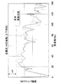
ここで、図2には2階床部22に強制外力が入力された際の周波数毎の床根太18の上下方向の振動レベル分布が示されており、図3には2階床部22に強制外力が入力された際の周波数毎の床根太18の左右方向(水平方向のうち、床根太18の長手方向に対して直交する方向)の振動レベル分布が示されている。これらのグラフにおいて、点線は従来構造の場合を示し、実線は本実施の形態の場合を示している。
Here, FIG. 2 shows the vibration level distribution in the vertical direction of the
これらのグラフからもわかるように、本実施の形態を適用した場合には、44.5Hzから89.1Hzまでの63Hz帯域の振動の振動レベルのピークを低減でき、しかも、63Hzの極近傍における周波数の振動レベルを低減できる。このように、本実施の形態では2階床部22に強制外力が入力された際に衝撃音の原因となる63Hz帯域における床根太18の振動レベルのピークを低減でき、衝撃音の原因となる帯域の床下地パネル24の振動を抑制できる。
As can be seen from these graphs, when this embodiment is applied, the peak of the vibration level of the 63 Hz band from 44.5 Hz to 89.1 Hz can be reduced, and the frequency in the very vicinity of 63 Hz can be reduced. The vibration level can be reduced. As described above, in this embodiment, the peak of the vibration level of the
一方で、天井本体14に設けられた平板部材16を天井本体14の一部とみなすと、天井本体14の質量が2倍程度に増加している。これにより、平板部材16を含む天井本体14全体の固有振動数が、天井本体14単独での固有振動数とは異なる値となる。上記のように、2階床部22の全体的な固有振動数が天井本体14単独での固有振動数に等しいのであれば、平板部材16を含む天井本体14全体、すなわち、1階天井部12の固有振動数は、2階床部22の全体的な固有振動数(すなわち、ダイナミックダンパ34が相殺させる2階床部22の振動の振動数)とは異なる値となる。
On the other hand, when the
このため、上部強制外力が床下地パネル24に入力されることで床下地パネル24が振動し、これにより、空間13内の空気に圧力が生じ、この空気の圧力により1階天井部12で振動が励起されても、1階天井部12の振動が防止又は振動が極めて効果的に抑制される。これにより、天井本体14の振動に起因した音の発生を防止又は極めて効果的に抑制できる。
For this reason, when the upper forced external force is input to the
また、1階天井部12の固有振動数をずらすという観点からすれば、平板部材16ではなく、例えば、ブロック状の質量体を天井本体14に適宜に取り付ければよい。しかしながら、本実施の形態では、質量体としての平板部材16が平板状であるため、天井本体14の一部に平板部材16の荷重が偏ることがなく、荷重バランスを簡単にとることができる。
Further, from the viewpoint of shifting the natural frequency of the first-
さらに、上記のように、1階天井部12の固有振動数をずらすという観点からすれば、平板部材16を設けずに、天井本体14そのものの板厚を変えて質量を増加させて対応してもよい。これに対して本実施の形態では、敢えて天井本体14に平板部材16を設ける構成とすることで、天井本体14に関しては従来の1階天井板を適用することができる。このため、本実施の形態(本発明)を適用しない1階天井板と本実施の形態における天井本体14とを併用でき、コストを安価にできる。
Furthermore, as described above, from the viewpoint of shifting the natural frequency of the first-
一方で、上記のように、床下地パネル24に上部強制外力が入力されて床下地パネル24が振動し、これにより生じた音は、床下地パネル24の下側に設けられた吸音材28によりその一部又は全部が吸収される。これにより、上記の音が空間13内の空気を介して1階天井部12に伝播することを防止又は極めて効果的に抑制できる。このため、この音に起因した天井本体14の振動が防止又は効果的に抑制され、ひいては、天井本体14が振動することに起因した音の発生を防止又は効果的に抑制できる。
On the other hand, as described above, the upper forcible external force is input to the
ここで、図4には2階床部22に強制外力が入力された際の周波数毎の1階室内音の音圧レベル分布が示されている。このグラフにおいて、点線は従来構造の場合を示し、実線は本実施の形態の場合を示している。
Here, FIG. 4 shows the sound pressure level distribution of the first-floor room sound for each frequency when a forced external force is input to the second-
このグラフに示されるように、本実施の形態を適用した場合には、極一部の周波数域で例外はあるものの、基本的に44.5Hzから89.1Hzまでの63Hz帯域の音圧レベルを低くでき、特に、63Hzの極近傍の周波数の音圧レベルを低くできる。このように、本実施の形態を適用することで、63Hz帯域で特に63Hz及びの極近傍の周波数の音圧レベルを抑制でき、1階室内の静粛性を向上できる。 As shown in this graph, when the present embodiment is applied, the sound pressure level in the 63 Hz band from 44.5 Hz to 89.1 Hz is basically used, although there are exceptions in some frequency ranges. In particular, the sound pressure level at a frequency in the vicinity of 63 Hz can be lowered. As described above, by applying this embodiment, the sound pressure level of the frequency near 63 Hz in the 63 Hz band can be suppressed, and the quietness in the first floor room can be improved.
しかも、63Hzの音に対して倍音の関係となる周波数の音又はこの帯域の音(例えば、126Hz及びその極近傍の周波数の音)もまた、63Hz帯域の音と共に音圧レベルが抑制される。これにより、1階室内の静粛性を更に向上できる。 In addition, the sound pressure level of a sound having a harmonic relationship with respect to a 63 Hz sound or a sound in this band (for example, a sound having a frequency of 126 Hz and the vicinity thereof) is also suppressed together with the sound of the 63 Hz band. Thereby, the quietness in the first floor room can be further improved.
<第2の実施の形態>
次に、本発明のその他の実施の形態について説明する。なお、以下の各実施の形態を説明するにあたり、前記第1の実施の形態を含めて説明している実施の形態よりも前出の実施の形態と基本的に同一の部位に関しては、同一の符号を付与してその詳細な説明を省略する。
<Second Embodiment>
Next, other embodiments of the present invention will be described. In describing each of the following embodiments, the same parts as those in the previous embodiment are basically the same as those in the embodiment described above including the first embodiment. Reference numerals are assigned and detailed description thereof is omitted.
図5には、本発明の第2の実施の形態に係る建物用制振構造を適用した建物としてのスチールハウス50の要部の構成の断面が概略的に示されている。
FIG. 5 schematically shows a cross section of a configuration of a main part of a
このスチールハウス50は、1階天井部12に代わり下階天井部としての1階天井部52を備えている。1階天井部52は天井本体14及び平板部材16を備えている点では前記第1の実施の形態における1階天井部12と同じである。但し、1階天井部52は加圧材としての吸音材54を備えている。吸音材54は、例えば、けい酸分と酸化カルシウム分を主成分とした人造鉱物繊維である所謂「ロックウール」により構成されている。
The
また、図5に示されるように、スチールハウス50は2階床部22に代わる上階床部としての2階床部56を備えている。2階床部56は吸音材28を備えていない点で2階床部22とは構成が異なる。なお、本実施の形態では、吸音材28を備えない2階床部56を適用したが、吸音材28を備える2階床部22を2階床部56に代えて適用しても構わない。
Further, as shown in FIG. 5, the
すなわち、以上の構成の本実施の形態は、2階床部56が吸音材28を備えておらず、代わりに吸音材54を備える構成である。前記第1の実施の形態における吸音材28も、本実施の形態における吸音材54も天井本体14と床下地パネル24との間に設けられていることに変わりはない。このため、本実施の形態も前記第1の実施の形態と基本的に同様の作用を奏し、前記第1の実施の形態と基本的に同様の効果を得ることができる。
That is, in the present embodiment having the above-described configuration, the second-
<第3の実施の形態>
次に、本発明の第3の実施の形態について説明する。
<Third Embodiment>
Next, a third embodiment of the present invention will be described.
図6には本実施の形態に係る建物用制振構造を適用した建物としてのユニット工法仕様の住宅70の要部の構成の断面が概略的に示されている。
FIG. 6 schematically shows a cross section of a configuration of a main part of a
この図に示されるように、住宅70では、床根太18に代わり床下地パネル24を支える断面矩形筒状の床小梁72の下端部には、平板状の支持板74が固定されている。支持板74は床小梁72の幅方向に沿った中央部で床小梁72に固定されており、床小梁72よりもその幅方向両側に延出された部分にはそれぞれダンパベース32が取り付けられており、各ダンパベース32にダイナミックダンパ34が取り付けられている。
As shown in this figure, in a
以上の構成の本実施の形態は、ダイナミックダンパ34の配置態様が前記第1の実施の形態とは異なるものの、基本的には前記第1の実施の形態と同様の構成であるため、本実施の形態でも前記第1の実施の形態と同様の作用を奏し、前記第1の実施の形態と同様の効果を得ることができる。
The present embodiment having the above configuration is basically the same as the first embodiment although the arrangement of the
10 スチールハウス(建物)
12 1階天井部(下階天井部)
13 空間
14 天井本体
16 平板部材(質量体)
22 2階床部(上階床部)
28 吸音材
34 ダイナミックダンパ(ダンパ)
50 スチールハウス(建物)
52 1階天井部(下階天井部)
54 吸音材
56 2階床部(上階床部)
70 住宅(建物)
10 Steel house (building)
12 1st floor ceiling (lower floor ceiling)
13
22 2nd floor (upper floor)
28
50 Steel house (building)
52 1st floor ceiling (lower floor ceiling)
54
70 House (building)
Claims (3)
前記上階床部の下方に設けられる天井本体を有する下階天井部と、
材質又は厚さが前記天井本体と同じ部材を有する平板部材により構成されて前記下階天上部を構成すると共に、前記下階天井部の上側で前記天井本体に設けられて前記天井本体に質量を付加し、前記天井本体の固有振動数を前記ダンパの固有振動数とは異なる値にずらす質量体と、
前記上階床部の一部として前記上階床部の下側で前記下階天井部側から上側へ離間した状態で設けられ、前記上階床部が振動することにより生じて前記下階天井部へ伝わる音の少なくとも一部を吸収する吸音材と、
を備える建物用制振構造。 A damper that is provided in the upper floor part and reduces the vibration of the upper floor part by oscillating in an opposite phase to the vibration of the upper floor part;
A lower floor ceiling portion having a ceiling body provided below the upper floor portion;
The material or thickness is composed of a flat plate member having the same member as the ceiling main body to form the upper part of the lower floor top, and is provided on the ceiling main body above the lower floor ceiling part so that the mass of the ceiling main body is increased. A mass body for shifting the natural frequency of the ceiling body to a value different from the natural frequency of the damper;
As a part of the upper floor part, the lower floor ceiling is provided on the lower side of the upper floor part and spaced apart from the lower floor ceiling part side, and is generated by the vibration of the upper floor part. A sound absorbing material that absorbs at least part of the sound transmitted to the part;
Vibration control structure for buildings.
Priority Applications (1)
| Application Number | Priority Date | Filing Date | Title |
|---|---|---|---|
| JP2006029742A JP4919673B2 (en) | 2006-02-07 | 2006-02-07 | Damping structure for buildings |
Applications Claiming Priority (1)
| Application Number | Priority Date | Filing Date | Title |
|---|---|---|---|
| JP2006029742A JP4919673B2 (en) | 2006-02-07 | 2006-02-07 | Damping structure for buildings |
Publications (2)
| Publication Number | Publication Date |
|---|---|
| JP2007211415A JP2007211415A (en) | 2007-08-23 |
| JP4919673B2 true JP4919673B2 (en) | 2012-04-18 |
Family
ID=38490099
Family Applications (1)
| Application Number | Title | Priority Date | Filing Date |
|---|---|---|---|
| JP2006029742A Active JP4919673B2 (en) | 2006-02-07 | 2006-02-07 | Damping structure for buildings |
Country Status (1)
| Country | Link |
|---|---|
| JP (1) | JP4919673B2 (en) |
Families Citing this family (4)
| Publication number | Priority date | Publication date | Assignee | Title |
|---|---|---|---|---|
| JP5435888B2 (en) * | 2008-05-01 | 2014-03-05 | 早川ゴム株式会社 | Ceiling structure and construction method |
| JP2011137288A (en) * | 2009-12-25 | 2011-07-14 | Toyota Home Kk | Building |
| JP6161957B2 (en) * | 2013-05-30 | 2017-07-12 | トヨタホーム株式会社 | Building floor structure |
| CN103758028B (en) * | 2014-01-07 | 2015-08-19 | 中铁大桥局集团武汉桥梁科学研究院有限公司 | A kind of tuning vibration absorber of low frequency mass and control method thereof |
Family Cites Families (7)
| Publication number | Priority date | Publication date | Assignee | Title |
|---|---|---|---|---|
| JPH05172183A (en) * | 1991-12-24 | 1993-07-09 | Ando Kensetsu Kk | Vibration resistant device for structure |
| JPH10183849A (en) * | 1996-12-26 | 1998-07-14 | Matsushita Electric Works Ltd | Soundproof ceiling structure |
| JP3624895B2 (en) * | 2001-09-27 | 2005-03-02 | ヤマハ株式会社 | Floor structure |
| JP2004003280A (en) * | 2002-03-27 | 2004-01-08 | Toyoda Gosei Co Ltd | Damping device for building including vibrationproof device for housing |
| JP2004190410A (en) * | 2002-12-13 | 2004-07-08 | Mitsui & Co Ltd | Sound absorbing material |
| JP4366492B2 (en) * | 2004-04-06 | 2009-11-18 | 旭化成ホームズ株式会社 | Ceiling structure |
| JP2005350888A (en) * | 2004-06-08 | 2005-12-22 | Matsushita Electric Works Ltd | Partition wall structure |
-
2006
- 2006-02-07 JP JP2006029742A patent/JP4919673B2/en active Active
Also Published As
| Publication number | Publication date |
|---|---|
| JP2007211415A (en) | 2007-08-23 |
Similar Documents
| Publication | Publication Date | Title |
|---|---|---|
| JP4919673B2 (en) | Damping structure for buildings | |
| JP5950750B2 (en) | Ceiling structure | |
| JP2006070494A (en) | Floor structure | |
| JP2020100947A (en) | Floor structure | |
| JP2007162247A (en) | Sound insulation floor structure of building | |
| JP2003247294A (en) | Sound-insulated floor structure | |
| JP4806253B2 (en) | Floor structure | |
| JP7074582B2 (en) | Building ceiling structure | |
| JP4930183B2 (en) | Damping floor structure | |
| JP7401090B2 (en) | double floor structure | |
| JP7201174B2 (en) | Ceiling anti-vibration material and ceiling anti-vibration structure | |
| JP2016037776A (en) | Floor structure | |
| JP7122185B2 (en) | floor structure | |
| JP7435271B2 (en) | Sound insulation structure | |
| JP4366492B2 (en) | Ceiling structure | |
| JP4867871B2 (en) | Sound insulation floor structure | |
| JP7037351B2 (en) | building | |
| JP7240197B2 (en) | floor structure | |
| JPH10183849A (en) | Soundproof ceiling structure | |
| JP4854558B2 (en) | Floor structure, building unit and unit building | |
| JP6453384B2 (en) | Sound insulation floor structure | |
| KR100629954B1 (en) | Structure of isolating a crashing sound of floor of a building | |
| JP2006125195A (en) | Floor structure | |
| JP2020176493A (en) | Floor structure | |
| JP5301204B2 (en) | Building floor impact noise reduction structure |
Legal Events
| Date | Code | Title | Description |
|---|---|---|---|
| A621 | Written request for application examination |
Free format text: JAPANESE INTERMEDIATE CODE: A621 Effective date: 20080509 |
|
| A711 | Notification of change in applicant |
Free format text: JAPANESE INTERMEDIATE CODE: A712 Effective date: 20101126 |
|
| A977 | Report on retrieval |
Free format text: JAPANESE INTERMEDIATE CODE: A971007 Effective date: 20101217 |
|
| RD03 | Notification of appointment of power of attorney |
Free format text: JAPANESE INTERMEDIATE CODE: A7423 Effective date: 20110307 |
|
| A131 | Notification of reasons for refusal |
Free format text: JAPANESE INTERMEDIATE CODE: A131 Effective date: 20110329 |
|
| A521 | Request for written amendment filed |
Free format text: JAPANESE INTERMEDIATE CODE: A523 Effective date: 20110530 |
|
| A131 | Notification of reasons for refusal |
Free format text: JAPANESE INTERMEDIATE CODE: A131 Effective date: 20110816 |
|
| A521 | Request for written amendment filed |
Free format text: JAPANESE INTERMEDIATE CODE: A523 Effective date: 20111007 |
|
| TRDD | Decision of grant or rejection written | ||
| A01 | Written decision to grant a patent or to grant a registration (utility model) |
Free format text: JAPANESE INTERMEDIATE CODE: A01 Effective date: 20120117 |
|
| A01 | Written decision to grant a patent or to grant a registration (utility model) |
Free format text: JAPANESE INTERMEDIATE CODE: A01 |
|
| A61 | First payment of annual fees (during grant procedure) |
Free format text: JAPANESE INTERMEDIATE CODE: A61 Effective date: 20120131 |
|
| R150 | Certificate of patent or registration of utility model |
Free format text: JAPANESE INTERMEDIATE CODE: R150 Ref document number: 4919673 Country of ref document: JP Free format text: JAPANESE INTERMEDIATE CODE: R150 |
|
| FPAY | Renewal fee payment (event date is renewal date of database) |
Free format text: PAYMENT UNTIL: 20150210 Year of fee payment: 3 |
|
| R250 | Receipt of annual fees |
Free format text: JAPANESE INTERMEDIATE CODE: R250 |
|
| R250 | Receipt of annual fees |
Free format text: JAPANESE INTERMEDIATE CODE: R250 |
|
| R250 | Receipt of annual fees |
Free format text: JAPANESE INTERMEDIATE CODE: R250 |
|
| R250 | Receipt of annual fees |
Free format text: JAPANESE INTERMEDIATE CODE: R250 |
|
| S111 | Request for change of ownership or part of ownership |
Free format text: JAPANESE INTERMEDIATE CODE: R313117 |
|
| R250 | Receipt of annual fees |
Free format text: JAPANESE INTERMEDIATE CODE: R250 |
|
| R350 | Written notification of registration of transfer |
Free format text: JAPANESE INTERMEDIATE CODE: R350 |
|
| R250 | Receipt of annual fees |
Free format text: JAPANESE INTERMEDIATE CODE: R250 |
|
| R250 | Receipt of annual fees |
Free format text: JAPANESE INTERMEDIATE CODE: R250 |
|
| R250 | Receipt of annual fees |
Free format text: JAPANESE INTERMEDIATE CODE: R250 |
|
| R250 | Receipt of annual fees |
Free format text: JAPANESE INTERMEDIATE CODE: R250 |
|
| R250 | Receipt of annual fees |
Free format text: JAPANESE INTERMEDIATE CODE: R250 |