JP4914547B2 - Method for operating a direct injection gasoline driven internal combustion engine - Google Patents
Method for operating a direct injection gasoline driven internal combustion engine Download PDFInfo
- Publication number
- JP4914547B2 JP4914547B2 JP2001287521A JP2001287521A JP4914547B2 JP 4914547 B2 JP4914547 B2 JP 4914547B2 JP 2001287521 A JP2001287521 A JP 2001287521A JP 2001287521 A JP2001287521 A JP 2001287521A JP 4914547 B2 JP4914547 B2 JP 4914547B2
- Authority
- JP
- Japan
- Prior art keywords
- spark
- mode
- duration
- combustion
- homogeneous
- Prior art date
- Legal status (The legal status is an assumption and is not a legal conclusion. Google has not performed a legal analysis and makes no representation as to the accuracy of the status listed.)
- Expired - Fee Related
Links
Images

Classifications
-
- F—MECHANICAL ENGINEERING; LIGHTING; HEATING; WEAPONS; BLASTING
- F02—COMBUSTION ENGINES; HOT-GAS OR COMBUSTION-PRODUCT ENGINE PLANTS
- F02P—IGNITION, OTHER THAN COMPRESSION IGNITION, FOR INTERNAL-COMBUSTION ENGINES; TESTING OF IGNITION TIMING IN COMPRESSION-IGNITION ENGINES
- F02P5/00—Advancing or retarding ignition; Control therefor
- F02P5/04—Advancing or retarding ignition; Control therefor automatically, as a function of the working conditions of the engine or vehicle or of the atmospheric conditions
- F02P5/045—Advancing or retarding ignition; Control therefor automatically, as a function of the working conditions of the engine or vehicle or of the atmospheric conditions combined with electronic control of other engine functions, e.g. fuel injection
-
- F—MECHANICAL ENGINEERING; LIGHTING; HEATING; WEAPONS; BLASTING
- F02—COMBUSTION ENGINES; HOT-GAS OR COMBUSTION-PRODUCT ENGINE PLANTS
- F02D—CONTROLLING COMBUSTION ENGINES
- F02D41/00—Electrical control of supply of combustible mixture or its constituents
- F02D41/24—Electrical control of supply of combustible mixture or its constituents characterised by the use of digital means
- F02D41/2406—Electrical control of supply of combustible mixture or its constituents characterised by the use of digital means using essentially read only memories
- F02D41/2409—Addressing techniques specially adapted therefor
- F02D41/2422—Selective use of one or more tables
-
- F—MECHANICAL ENGINEERING; LIGHTING; HEATING; WEAPONS; BLASTING
- F02—COMBUSTION ENGINES; HOT-GAS OR COMBUSTION-PRODUCT ENGINE PLANTS
- F02D—CONTROLLING COMBUSTION ENGINES
- F02D41/00—Electrical control of supply of combustible mixture or its constituents
- F02D41/30—Controlling fuel injection
- F02D41/3011—Controlling fuel injection according to or using specific or several modes of combustion
- F02D41/3017—Controlling fuel injection according to or using specific or several modes of combustion characterised by the mode(s) being used
- F02D41/3023—Controlling fuel injection according to or using specific or several modes of combustion characterised by the mode(s) being used a mode being the stratified charge spark-ignited mode
- F02D41/3029—Controlling fuel injection according to or using specific or several modes of combustion characterised by the mode(s) being used a mode being the stratified charge spark-ignited mode further comprising a homogeneous charge spark-ignited mode
-
- F—MECHANICAL ENGINEERING; LIGHTING; HEATING; WEAPONS; BLASTING
- F02—COMBUSTION ENGINES; HOT-GAS OR COMBUSTION-PRODUCT ENGINE PLANTS
- F02P—IGNITION, OTHER THAN COMPRESSION IGNITION, FOR INTERNAL-COMBUSTION ENGINES; TESTING OF IGNITION TIMING IN COMPRESSION-IGNITION ENGINES
- F02P3/00—Other installations
- F02P3/02—Other installations having inductive energy storage, e.g. arrangements of induction coils
- F02P3/04—Layout of circuits
- F02P3/045—Layout of circuits for control of the dwell or anti dwell time
-
- F—MECHANICAL ENGINEERING; LIGHTING; HEATING; WEAPONS; BLASTING
- F02—COMBUSTION ENGINES; HOT-GAS OR COMBUSTION-PRODUCT ENGINE PLANTS
- F02P—IGNITION, OTHER THAN COMPRESSION IGNITION, FOR INTERNAL-COMBUSTION ENGINES; TESTING OF IGNITION TIMING IN COMPRESSION-IGNITION ENGINES
- F02P9/00—Electric spark ignition control, not otherwise provided for
- F02P9/002—Control of spark intensity, intensifying, lengthening, suppression
-
- F—MECHANICAL ENGINEERING; LIGHTING; HEATING; WEAPONS; BLASTING
- F02—COMBUSTION ENGINES; HOT-GAS OR COMBUSTION-PRODUCT ENGINE PLANTS
- F02B—INTERNAL-COMBUSTION PISTON ENGINES; COMBUSTION ENGINES IN GENERAL
- F02B75/00—Other engines
- F02B75/12—Other methods of operation
- F02B2075/125—Direct injection in the combustion chamber for spark ignition engines, i.e. not in pre-combustion chamber
-
- F—MECHANICAL ENGINEERING; LIGHTING; HEATING; WEAPONS; BLASTING
- F02—COMBUSTION ENGINES; HOT-GAS OR COMBUSTION-PRODUCT ENGINE PLANTS
- F02B—INTERNAL-COMBUSTION PISTON ENGINES; COMBUSTION ENGINES IN GENERAL
- F02B23/00—Other engines characterised by special shape or construction of combustion chambers to improve operation
- F02B23/08—Other engines characterised by special shape or construction of combustion chambers to improve operation with positive ignition
- F02B23/10—Other engines characterised by special shape or construction of combustion chambers to improve operation with positive ignition with separate admission of air and fuel into cylinder
- F02B23/101—Other engines characterised by special shape or construction of combustion chambers to improve operation with positive ignition with separate admission of air and fuel into cylinder the injector being placed on or close to the cylinder centre axis, e.g. with mixture formation using spray guided concepts
-
- Y—GENERAL TAGGING OF NEW TECHNOLOGICAL DEVELOPMENTS; GENERAL TAGGING OF CROSS-SECTIONAL TECHNOLOGIES SPANNING OVER SEVERAL SECTIONS OF THE IPC; TECHNICAL SUBJECTS COVERED BY FORMER USPC CROSS-REFERENCE ART COLLECTIONS [XRACs] AND DIGESTS
- Y02—TECHNOLOGIES OR APPLICATIONS FOR MITIGATION OR ADAPTATION AGAINST CLIMATE CHANGE
- Y02T—CLIMATE CHANGE MITIGATION TECHNOLOGIES RELATED TO TRANSPORTATION
- Y02T10/00—Road transport of goods or passengers
- Y02T10/10—Internal combustion engine [ICE] based vehicles
- Y02T10/12—Improving ICE efficiencies
Description
【0001】
【発明の属する技術分野】
本発明は、直接噴射ガソリン駆動内燃機関を作動する方法に関する。
【0002】
【従来の技術】
直接噴射ガソリン駆動内燃機関を作動する一般的方法は、例えばDE19730908A1により既知である。内燃機関がアイドリング・モードにある場合は、少量の燃料しか燃焼スペースに噴射されず、その結果、層状給気モードでの混合気点火には最大5ミリ秒の長い火花継続時間が必要である。導入される燃料が少量であるので、火花プラグの電極における混合が、混合気雲の縁における点火には希薄すぎるが、給気の交替中に、燃焼スペースを通る流れが一時的に電極間に点火可能な混合気を移動させ、これは長い火花継続時間を通して続く点火火花によって確実に燃焼する。内燃機関の負荷が増加するにつれ、噴射量が増加し、混合気の燃焼には、それに応じて短縮された火花継続時間で十分になる。内燃機関の全負荷モードでは、均質の混合気の形成が生じ、良好な混合気の準備により、可燃性混合気のみが電極間に存在し、点火には約0.1ミリ秒という最短の火花継続時間で十分になる。制御装置が設けられ、これは内燃機関の少なくとも1つの作動パラメータに基づき、火花継続時間に関する情報を伴う制御信号を生成し、これを点火装置に供給する。
【0003】
このタイプの直接噴射ガソリン駆動内燃機関の作動において、1つの欠点は、均質モードで点火するために、約0.1ミリ秒という最短の火花継続時間が提供されるが、層状給気モードで点火するには、長い火花継続時間が提供され、均質モードと層状給気モードとの区別がなく、したがって火花の燃焼継続時間が高い精度で設定されないことである。
【0004】
【発明が解決しようとする課題】
したがって、本発明の目的は、均質モードでも層状給気モードでも最適な燃焼が生じるような方法で、直接噴射ガソリン駆動内燃機関の作動を改良することである。
【0005】
【課題を解決するための手段】
この目的は、本発明によれば、請求項1の特徴によって達成される。本発明の主題の有利な改善および発展は、従属請求項の特徴によって特徴付けられる。
【0006】
この配置構成の基本的な利点は、直接噴射ガソリン駆動内燃機関に関する場合、火花の継続時間が燃焼スペース内で優勢な状態と正確に調和する最適な燃焼が生じることである。というのは、層状給気モードでは、ガソリン・エンジンを均質モードで作動する場合とは異なり、混合気はもはや燃焼性混合気として燃焼スペース全体には分布しないので、直接噴射ガソリン・エンジンの点火装置は、新しい要件に適合しなければならない。層状給気モードでは、混合気雲は、混合気に確実に点火できるように、正確な時間に正確な組成で火花プラグに存在しなければならない。火花継続時間が短すぎる場合は、点火火花の点火が早すぎる、または遅すぎるため、混合気の準備における周期的変動が、燃焼の誤点火をもたらすことがある。したがって、非均質な混合気に点火するために、可能な限り長い火花燃焼継続時間が最適である。しかし、長い火花燃焼継続時間は、高い火花プラグの摩耗をもたらす。この影響を打ち消すために、直接噴射ガソリン・エンジンを均質モードで作動する間に、火花燃焼継続時間を大幅に短縮することができる。というのは、この作動モードでは、混合気は高度に燃焼性の混合気であり、したがって混合気の確実な燃焼には、非常に小さい点火エネルギーしか必要でないからである。均質モードと層状給気モードとを区別することにより、さらなる補正要素も組み込むことができ、したがって火花プラグが過度に摩耗せず、最適な火花燃焼継続時間が設定され、最適な燃焼が生じる。
【0007】
本発明について、図の説明と関連して、例示的実施形態によってさらに詳細に説明する。
【0008】
【発明の実施の形態】
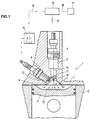
図1は、直接噴射ガソリン駆動内燃機関1、シリンダ3の縦断面図であり、その中でピストン2が、縦方向に移動可能で、燃焼スペース4を限定するよう配置される。シリンダ・ヘッド5がシリンダ3を覆い、燃焼スペース4を閉鎖する。燃焼スペース4へのアクセスを有するインジェクタ6が、シリンダ・ヘッド5内で、シリンダ軸14上の中心位置に配置され、混合気を形成するために、吸気ダクト(図示せず)を介して別々に供給される燃焼空気とともに、燃焼スペースに燃料を噴射する。この場合、燃料は、インジェクタ6の円錐形射出ノズルを通して燃焼スペース4の中心に、ピストン2に向かって広がる円錐形の射出7で噴射される。内燃機関1の広い特性マップ範囲内で、個々のシリンダ3の仕事サイクルにおける圧縮行程中の燃料噴射によって層状給気モードが提供される。円錐形射出7は、ピストン2の圧縮行程中に噴射され、その結果、層状混合気雲13が燃焼スペースの中心位置に形成される。この場合の燃料濃度は、混合気雲13の芯から円錐形射出7の射出縁に向かって減少する。給気の層状化により、特に部分負荷範囲では、混合気が燃焼スペース4の大きい部分で希薄になり、燃焼する燃料の量が主に中心に供給されるので、消費量に関する利点が達成される。
【0009】
火花プラグ9は、その電極10、11が燃焼スペースのルーフ8から燃焼スペース4内へと突出し、それと同時に円錐形射出7または混合気雲13の縁領域に存在するような方法で、シリンダ・ヘッド5内に配置される。射出の縁領域に配置することにより、電極10、11が燃料で濡れることがほぼ防止され、それに伴い、火花プラグ9の絶縁体足部12への有害な滑動放電を招く付着物の形成が防止される。混合気雲13に点火するために、中央電極10と、電気的にシリンダ・ヘッド5に接続されたアース電極11との間に点火装置15によって電気フラッシュオーバ電圧が印加され、点火火花が誘発される。点火装置は、交流電圧を生成し、約12マイクロ秒という短期間に必要なフラッシュオーバ電圧を変圧して、点火装置の点火コイルに充電する。このような高い電圧の急速な蓄積により、所望の量で対応するエネルギー束が連続的に生成され、その結果、所望の長さの点火火花が獲得される。さらに、高電圧の急速な蓄積は、電極10、11の煤形成および絶縁体足部12のおかげで、抵抗分流による損失が低くなり、大きい高電圧を生成することが可能になる。さらに、急速に蓄積された高電圧は、電極間の火花ブレークスルーに伝導し、点火絶縁体12上の滑動放電を防止する。内燃機関1の個々の作動点に応じて、制御装置16は、必要な火花継続時間に関する情報を有する制御信号18を生成し、前記制御信号は、火花プラグ9による混合気点火を誘発するために、点火装置15に供給される。優勢な作動点を決定するために、回転数(回転速度)、作動負荷など、内燃機関1の様々な作動パラメータ19に関して連続的に決定された測定データを制御装置16に供給し、必要な火花継続時間を決定するベースとして見なす。制御装置16は、特性マップ・メモリ17から、そこに格納され、内燃機関の優勢な作動点における点火の確実性および最適動作のために予め決定された火花継続時間に関するアサインメント情報20を検出する。したがって、混合気雲13の縁領域に存在する電極10、11による確実な混合気燃焼が、エネルギーに関して最小の支出で保証される。長い火花継続時間は、燃焼スペースを通る流れにより、放電交替中に電極10、11に一時的に存在する点火可能な混合気のボリュームが、点火火花によって覆われることを保証する。内燃機関1がアイドリング・モードにある場合は、少量の燃料しか燃焼スペース4に噴射されず、その結果、層状給気モードで混合気に点火するには、最大5ミリ秒という長い火花継続時間が必要である。導入される燃料が少量なので、火花プラグ9の電極10、11における混合気は、混合気雲13の縁で点火するには希薄すぎるが、給気の交替中に、燃焼スペースを通る流れが一時的に電極10、11間に点火可能な混合気を移動させ、これは長い火花継続時間を通して続く点火火花によって確実に燃焼する。内燃機関の負荷が増加するにつれ、噴射量が増加し、混合気の燃焼には、それに応じて短縮された火花継続時間で十分になる。内燃機関の全負荷モードでは、均質の混合気の形成が生じ、良好な混合気の準備により、可燃性混合気のみが電極間に存在し、点火には約0.1ミリ秒という最短の火花継続時間で十分になる。
【0010】
図2は、火花継続時間を設定するための特性マップの略図を示し、この特性マップは制御装置に格納される。これらの特性マップは、エンジン上で事前に測定される。火花燃焼継続時間tbdを制御する様々な特性マップが、均質モードおよび層状給気モードのために用意される。均質モードでは、火花燃焼継続時間tbdは、空燃比に対応する補正係数λによって補正される。さらに、層状給気モードと均質モードとの両方で、火花燃焼継続時間は、排ガス再循環(AGR)の補正係数およびエンジン温度の補正係数によって、および回転数勾配および負荷勾配によっても補正される。均質および層状給気モードの特性マップは、2つの基本的な特性マップで構成され、これは各場合に、回転数および負荷に対して均質および層状給気エンジン・モードの最適火花燃焼継続時間を含む。これらの最適な火花燃焼継続時間は、試験スタンド上で決定しなければならない。均質モードと層状給気モードでは、エンジンの作動状態に応じて、火花燃焼継続時間に変化がある。均質エンジン・モードでは、混合気がより希薄または濃厚になることがある。その結果として増加する火花エネルギー要件を満足させるために、均質基本特性マップからの火花燃焼継続時間に「補正係数燃空比」を掛ける。この係数は、均質エンジン・モードにしか作用しない。制御可能な外部排ガス再循環を、エンジンの燃焼温度、したがってNoxエミッションの低下の手段として使用してもよい。特に層状給気エンジン・モードでは、Noxエミッションは、エンジンへの措置によって低下しなければならない。非理論混合気(λ>0)のため、三元触媒をエミッション抑制に使用できないからである。出口ダクトから出て燃焼スペースに入る燃焼済み混合気の再循環は、その混合気を希釈することになり、その結果、点火エネルギー要件が上昇する。外部排ガス再循環AGRは、均質モードと層状給気エンジン・モードの双方で効果を生ずる。したがって、補正係数AGR動作は、補正した基本特性マップから、個々の火花燃焼継続時間に作用する。外部排ガス再循環の状態でモータを作動すると、回転数および負荷に応じて、「補正係数AGR」による火花燃焼継続時間の延長がある。その後、特性マップから決定された火花燃焼継続時間に、負荷勾配に依存する係数を掛ける。回転数勾配は、同様に、係数を介して火花燃焼継続時間に組み込まれる。回転数および負荷が急増する場合の遷移エンジン作動において、好ましくない非燃焼状態も発生することがあり、この理由から、この作動状態では火花継続時間の延長も好都合である。該当する特性曲線は、勾配の各場合に使用してもよい。直接噴射ガソリン・エンジンのシリンダに燃料を直接噴射するために、初期に噴射する均質モードでも、混合気の準備には非常に短い時間しか使用することができない。その結果、特に低温エンジンの場合は、不燃焼問題が発生する。というのは、可燃性混合気を生成するために、大量の燃料をシリンダに導入するからである。エンジンの低温時に、火花継続時間が増加し、したがって火花エネルギーが増加すると、良好な低温始動挙動に寄与する。エンジン温度が所望の火花燃焼継続時間に与える影響を、同様に特性曲線から検索する。火花燃焼継続時間が無限に増加しないように、火花燃焼継続時間を、点火装置への出力前に最小値および/または最大値に制限することもできる。
【図面の簡単な説明】
【図1】直接噴射ガソリン駆動内燃機関のシリンダの縦断面図である。
【図2】火花継続時間を設定する特性マップを示す図である。
【符号の説明】
1 内燃機関
2 ピストン
3 シリンダ
4 燃焼スペース
5 シリンダ・ヘッド
6 インジェクタ
7 射出
9 火花プラグ
10 電極
11 電極
12 絶縁体足部
13 混合気雲
14 シリンダ軸
15 点火装置
16 制御装置
17 特性マップ・メモリ
20 アサインメント情報[0001]
BACKGROUND OF THE INVENTION
The present invention relates to a method of operating a direct injection gasoline driven internal combustion engine.
[0002]
[Prior art]
A general method of operating a direct injection gasoline driven internal combustion engine is known, for example, from DE 19730908 A1. When the internal combustion engine is in idling mode, only a small amount of fuel is injected into the combustion space, so that mixture ignition in the stratified charge mode requires a long spark duration of up to 5 milliseconds. Because the amount of fuel introduced is small, mixing at the spark plug electrodes is too dilute for ignition at the edge of the mixture cloud, but during the charge change, the flow through the combustion space is temporarily between the electrodes. It moves the ignitable mixture, which is reliably burned by the igniting spark that continues through the long spark duration. As the load on the internal combustion engine increases, the injection quantity increases, and a correspondingly reduced spark duration is sufficient for combustion of the mixture. In the full load mode of the internal combustion engine, a homogeneous mixture formation occurs, and with a good mixture preparation, only a combustible mixture is present between the electrodes and the shortest spark of about 0.1 milliseconds for ignition. The duration is sufficient. A control device is provided, which generates a control signal with information on the spark duration based on at least one operating parameter of the internal combustion engine and supplies it to the ignition device.
[0003]
In the operation of this type of direct injection gasoline driven internal combustion engine, one drawback is that a short spark duration of about 0.1 milliseconds is provided to ignite in homogeneous mode, but ignition in stratified charge mode To provide a long spark duration, there is no distinction between homogeneous mode and stratified charge mode, and therefore the spark burning duration is not set with high accuracy.
[0004]
[Problems to be solved by the invention]
Accordingly, it is an object of the present invention to improve the operation of a direct injection gasoline driven internal combustion engine in such a way that optimum combustion occurs in both homogeneous and stratified charge modes.
[0005]
[Means for Solving the Problems]
This object is achieved according to the invention by the features of
[0006]
The basic advantage of this arrangement is that, for a direct injection gasoline driven internal combustion engine, an optimal combustion occurs that precisely matches the prevailing conditions in the combustion space for the duration of the spark. This is because, in stratified charge mode, the mixture is no longer distributed throughout the combustion space as a combustible mixture, unlike when the gasoline engine is operated in homogeneous mode, so that the direct-injection gasoline engine ignition system Must meet the new requirements. In the stratified charge mode, the mixture cloud must be present in the spark plug with the correct composition at the correct time to ensure that the mixture can be ignited. If the spark duration is too short, the igniting sparks are ignited too early or too late, so that periodic fluctuations in the mixture preparation can lead to misfires of combustion. Therefore, the longest possible spark combustion duration is optimal for igniting a heterogeneous mixture. However, long spark burning durations result in high spark plug wear. To counteract this effect, the spark combustion duration can be significantly reduced while operating the direct injection gasoline engine in homogeneous mode. This is because in this mode of operation, the mixture is a highly flammable mixture and therefore very little ignition energy is required for reliable combustion of the mixture. By distinguishing between homogeneous and stratified charge modes, additional correction elements can also be incorporated, so that the spark plug does not wear excessively, an optimal spark burn duration is set, and optimal combustion occurs.
[0007]
The invention is explained in more detail by means of exemplary embodiments in connection with the description of the figures.
[0008]
DETAILED DESCRIPTION OF THE INVENTION
FIG. 1 is a longitudinal sectional view of a direct-injection gasoline-driven
[0009]
The spark plug 9 is connected to the cylinder head in such a way that its
[0010]
FIG. 2 shows a schematic diagram of a characteristic map for setting the spark duration, which is stored in the control device. These characteristic maps are measured in advance on the engine. Various characteristic maps that control the spark combustion duration tbd are provided for the homogeneous mode and the stratified charge mode. In the homogeneous mode, the spark combustion duration tbd is corrected by the correction coefficient λ corresponding to the air-fuel ratio. Furthermore, in both the stratified charge mode and the homogeneous mode, the spark combustion duration is corrected by an exhaust gas recirculation (AGR) correction factor and an engine temperature correction factor, and also by a rotational speed gradient and a load gradient. The homogenous and stratified charge mode characteristic map consists of two basic characteristic maps, which in each case represent the optimum spark combustion duration for the homogeneous and stratified charge engine mode for speed and load. Including. These optimum spark burning durations must be determined on the test stand. In the homogeneous mode and the stratified charge mode, the spark combustion duration varies depending on the operating state of the engine. In homogeneous engine mode, the air / fuel mixture may become leaner or richer. In order to satisfy the resulting spark energy requirement, the spark combustion duration from the homogeneous basic property map is multiplied by the “correction factor fuel-air ratio”. This factor only affects the homogeneous engine mode. Controllable external exhaust gas recirculation may be used as a means of reducing engine combustion temperature and thus Nox emissions. Especially in the stratified charge engine mode, Nox emissions must be reduced by actions on the engine. This is because the three-way catalyst cannot be used for emission suppression because of the non-theoretical mixture (λ> 0). Recirculation of the burned mixture exiting the exit duct and entering the combustion space will dilute the mixture, resulting in increased ignition energy requirements. External exhaust gas recirculation AGR is effective in both homogeneous mode and stratified charge engine mode. Therefore, the correction coefficient AGR operation affects the individual spark combustion duration from the corrected basic characteristic map. When the motor is operated in the state of external exhaust gas recirculation, the spark combustion duration time is extended by the “correction coefficient AGR” according to the rotational speed and load. Thereafter, the spark combustion duration determined from the characteristic map is multiplied by a coefficient depending on the load gradient. The speed gradient is likewise incorporated into the spark combustion duration via a factor. In transition engine operation where the speed and load increase rapidly, undesirable non-combustion conditions may also occur and for this reason it is also advantageous to extend the spark duration. The relevant characteristic curve may be used in each case of the gradient. In order to inject fuel directly into the cylinder of a direct injection gasoline engine, even in the homogeneous mode in which it is initially injected, only a very short time can be used to prepare the mixture. As a result, non-combustion problems occur, particularly in the case of low temperature engines. This is because a large amount of fuel is introduced into the cylinder to produce a combustible mixture. When the engine is cold, the spark duration increases, and thus the spark energy increases contributes to good cold start behavior. Similarly, the effect of the engine temperature on the desired spark combustion duration is retrieved from the characteristic curve. The spark combustion duration can also be limited to a minimum and / or maximum value before output to the igniter so that the spark combustion duration does not increase indefinitely.
[Brief description of the drawings]
FIG. 1 is a longitudinal sectional view of a cylinder of a direct injection gasoline-driven internal combustion engine.
FIG. 2 is a diagram showing a characteristic map for setting a spark duration.
[Explanation of symbols]
DESCRIPTION OF
Claims (3)
Applications Claiming Priority (2)
| Application Number | Priority Date | Filing Date | Title |
|---|---|---|---|
| DE10046693.1 | 2000-09-21 | ||
| DE10046693A DE10046693B4 (en) | 2000-09-21 | 2000-09-21 | Method for operating a direct injection Otto internal combustion engine |
Publications (2)
| Publication Number | Publication Date |
|---|---|
| JP2002138933A JP2002138933A (en) | 2002-05-17 |
| JP4914547B2 true JP4914547B2 (en) | 2012-04-11 |
Family
ID=7657027
Family Applications (1)
| Application Number | Title | Priority Date | Filing Date |
|---|---|---|---|
| JP2001287521A Expired - Fee Related JP4914547B2 (en) | 2000-09-21 | 2001-09-20 | Method for operating a direct injection gasoline driven internal combustion engine |
Country Status (3)
| Country | Link |
|---|---|
| EP (1) | EP1191212A3 (en) |
| JP (1) | JP4914547B2 (en) |
| DE (1) | DE10046693B4 (en) |
Families Citing this family (5)
| Publication number | Priority date | Publication date | Assignee | Title |
|---|---|---|---|---|
| JP4030401B2 (en) * | 2002-09-27 | 2008-01-09 | 本田技研工業株式会社 | 4-cycle direct injection engine |
| DE10331267A1 (en) * | 2003-07-10 | 2005-02-03 | Robert Bosch Gmbh | fuel injection system |
| DE102006051439B4 (en) * | 2006-10-31 | 2009-01-29 | Continental Automotive Gmbh | Method for controlling an internal combustion engine |
| DE102010042318A1 (en) * | 2010-10-12 | 2012-04-12 | Bayerische Motoren Werke Ag | Ignition system with optional spark-ignition and partial-discharge ignition depending on the engine load |
| CN110651118B (en) * | 2017-05-24 | 2021-09-07 | 日产自动车株式会社 | Method and device for controlling internal combustion engine |
Family Cites Families (17)
| Publication number | Priority date | Publication date | Assignee | Title |
|---|---|---|---|---|
| JPS61268872A (en) * | 1985-05-23 | 1986-11-28 | Nissan Motor Co Ltd | Ignitor for creepage discharge plug |
| JPS62223461A (en) * | 1986-03-20 | 1987-10-01 | Nissan Motor Co Ltd | Ignition device for internal combustion engine |
| JPS63138122A (en) * | 1986-11-28 | 1988-06-10 | Mazda Motor Corp | Stratified combustion control device for engine |
| JP2652550B2 (en) * | 1988-03-11 | 1997-09-10 | 富士通テン株式会社 | Continuous ignition control system for internal combustion engine |
| US5170760A (en) * | 1990-11-13 | 1992-12-15 | Yamaha Hatsudoki Babushiki Kaisha | Ignition system for two cycle engine |
| US5333593A (en) * | 1993-01-15 | 1994-08-02 | Ford Motor Company | Energy-on-demand ignition coil |
| JPH07103122A (en) * | 1993-09-30 | 1995-04-18 | Mazda Motor Corp | Ignition device for engine |
| DE19612150A1 (en) * | 1996-03-27 | 1997-10-02 | Bosch Gmbh Robert | Control device for fuel-injected engine |
| JP3211677B2 (en) * | 1996-08-28 | 2001-09-25 | 三菱自動車工業株式会社 | Ignition timing control system for in-cylinder injection internal combustion engine |
| JP3761654B2 (en) * | 1996-12-10 | 2006-03-29 | 株式会社日本自動車部品総合研究所 | Combustion state detection device |
| DE19730908C2 (en) * | 1997-07-18 | 2002-11-28 | Daimler Chrysler Ag | Method for operating a direct-injection Otto engine |
| JP3464145B2 (en) * | 1998-04-24 | 2003-11-05 | 株式会社日本自動車部品総合研究所 | Ignition device for internal combustion engine |
| JP2000052817A (en) * | 1998-08-06 | 2000-02-22 | Nissan Motor Co Ltd | Controller for vehicle |
| JP3654010B2 (en) * | 1998-10-19 | 2005-06-02 | 日産自動車株式会社 | Control device for internal combustion engine |
| JP3534634B2 (en) * | 1999-01-06 | 2004-06-07 | 株式会社日立製作所 | Control device for internal combustion engine |
| JP4259717B2 (en) * | 1999-08-02 | 2009-04-30 | 株式会社日本自動車部品総合研究所 | Spark ignition device |
| DE10031874A1 (en) * | 2000-06-30 | 2002-01-17 | Bosch Gmbh Robert | Ignition device has controller that sets up closing time of switch based on current operation mode of internal combustion engine and on second operating parameter |
-
2000
- 2000-09-21 DE DE10046693A patent/DE10046693B4/en not_active Expired - Fee Related
-
2001
- 2001-09-13 EP EP01121971A patent/EP1191212A3/en not_active Withdrawn
- 2001-09-20 JP JP2001287521A patent/JP4914547B2/en not_active Expired - Fee Related
Also Published As
| Publication number | Publication date |
|---|---|
| DE10046693A1 (en) | 2002-04-11 |
| DE10046693B4 (en) | 2011-07-21 |
| JP2002138933A (en) | 2002-05-17 |
| EP1191212A2 (en) | 2002-03-27 |
| EP1191212A3 (en) | 2002-10-09 |
Similar Documents
| Publication | Publication Date | Title |
|---|---|---|
| US4621599A (en) | Method and apparatus for operating direct injection type internal combustion engine | |
| US6176215B1 (en) | Method for operation of a direct-injection spark-ignition internal combustion engine | |
| CN101037968B (en) | First and second spark plugs for improved combustion control | |
| US5207058A (en) | Internal combustion engine | |
| JP4469528B2 (en) | Method for operation of an internal combustion engine | |
| KR101016924B1 (en) | Fuel injection control apparatus and fuel injection control method of internal combustion engine | |
| US6948474B2 (en) | Cylinder direct injection type internal combustion engine | |
| WO2016042718A1 (en) | Control apparatus for internal combustion engine | |
| JP4259717B2 (en) | Spark ignition device | |
| JP6056775B2 (en) | Control device for internal combustion engine | |
| JP2007270658A (en) | Cylinder injection spark ignition type internal combustion engine | |
| US6176216B1 (en) | Ignition control for fuel direct injection type engine | |
| CN113825900B (en) | Control device for internal combustion engine | |
| JP4089109B2 (en) | Ignition control device for internal combustion engine | |
| US5941208A (en) | Process for operating an Otto internal-combustion engine having an internal mixture formation | |
| JP4914547B2 (en) | Method for operating a direct injection gasoline driven internal combustion engine | |
| JP2006500509A (en) | Self-igniting internal combustion engine | |
| EP1164276B1 (en) | Internal combustion engine with external assist for stable auto-ignition | |
| JP2007064187A (en) | Knock suppression device for internal combustion engine | |
| US6244247B1 (en) | Ignition device for internal combustion engines | |
| JP2001207890A (en) | Combustion control device of internal combustion engine | |
| KR100846922B1 (en) | Method of operating a direct fuel injected internal combustion engine | |
| RU2123121C1 (en) | Method of operation of internal combustion engine | |
| JP6965853B2 (en) | Premixed compression ignition engine | |
| JP2010116879A (en) | Ignition control device or ignition control method for internal combustion engine |
Legal Events
| Date | Code | Title | Description |
|---|---|---|---|
| A621 | Written request for application examination |
Free format text: JAPANESE INTERMEDIATE CODE: A621 Effective date: 20080820 |
|
| A131 | Notification of reasons for refusal |
Free format text: JAPANESE INTERMEDIATE CODE: A131 Effective date: 20091013 |
|
| A601 | Written request for extension of time |
Free format text: JAPANESE INTERMEDIATE CODE: A601 Effective date: 20091217 |
|
| A602 | Written permission of extension of time |
Free format text: JAPANESE INTERMEDIATE CODE: A602 Effective date: 20091222 |
|
| A521 | Written amendment |
Free format text: JAPANESE INTERMEDIATE CODE: A523 Effective date: 20100203 |
|
| A131 | Notification of reasons for refusal |
Free format text: JAPANESE INTERMEDIATE CODE: A131 Effective date: 20100706 |
|
| A601 | Written request for extension of time |
Free format text: JAPANESE INTERMEDIATE CODE: A601 Effective date: 20100929 |
|
| A602 | Written permission of extension of time |
Free format text: JAPANESE INTERMEDIATE CODE: A602 Effective date: 20101004 |
|
| A521 | Written amendment |
Free format text: JAPANESE INTERMEDIATE CODE: A523 Effective date: 20101105 |
|
| A131 | Notification of reasons for refusal |
Free format text: JAPANESE INTERMEDIATE CODE: A131 Effective date: 20110201 |
|
| A601 | Written request for extension of time |
Free format text: JAPANESE INTERMEDIATE CODE: A601 Effective date: 20110427 |
|
| A602 | Written permission of extension of time |
Free format text: JAPANESE INTERMEDIATE CODE: A602 Effective date: 20110506 |
|
| A521 | Written amendment |
Free format text: JAPANESE INTERMEDIATE CODE: A523 Effective date: 20110530 |
|
| TRDD | Decision of grant or rejection written | ||
| A01 | Written decision to grant a patent or to grant a registration (utility model) |
Free format text: JAPANESE INTERMEDIATE CODE: A01 Effective date: 20120104 |
|
| A01 | Written decision to grant a patent or to grant a registration (utility model) |
Free format text: JAPANESE INTERMEDIATE CODE: A01 |
|
| A61 | First payment of annual fees (during grant procedure) |
Free format text: JAPANESE INTERMEDIATE CODE: A61 Effective date: 20120123 |
|
| R150 | Certificate of patent or registration of utility model |
Free format text: JAPANESE INTERMEDIATE CODE: R150 |
|
| FPAY | Renewal fee payment (event date is renewal date of database) |
Free format text: PAYMENT UNTIL: 20150127 Year of fee payment: 3 |
|
| R250 | Receipt of annual fees |
Free format text: JAPANESE INTERMEDIATE CODE: R250 |
|
| LAPS | Cancellation because of no payment of annual fees |