JP4911674B2 - Heat fixing member and heat fixing device - Google Patents
Heat fixing member and heat fixing device Download PDFInfo
- Publication number
- JP4911674B2 JP4911674B2 JP2006040102A JP2006040102A JP4911674B2 JP 4911674 B2 JP4911674 B2 JP 4911674B2 JP 2006040102 A JP2006040102 A JP 2006040102A JP 2006040102 A JP2006040102 A JP 2006040102A JP 4911674 B2 JP4911674 B2 JP 4911674B2
- Authority
- JP
- Japan
- Prior art keywords
- heat fixing
- fixing member
- elastic layer
- heat
- carbon fiber
- Prior art date
- Legal status (The legal status is an assumption and is not a legal conclusion. Google has not performed a legal analysis and makes no representation as to the accuracy of the status listed.)
- Expired - Fee Related
Links
Images


Description
本発明は、加熱定着部材と加圧部材との圧接ニップ部にシート状の被記録材を挟持搬送して被記録材を加熱し、該被記録材上の未定着トナー画像を溶融し定着する加熱定着装置における加熱定着部材および該加熱定着部材を具備した加熱定着装置に関する。 In the present invention, a sheet-like recording material is sandwiched and conveyed at a pressure nip portion between a heat fixing member and a pressure member to heat the recording material, and an unfixed toner image on the recording material is melted and fixed. The present invention relates to a heat fixing member in a heat fixing device and a heat fixing device including the heat fixing member.
一般に、電子写真方式に用いられる加熱定着装置では、加熱ローラと他のローラとが圧接されているか、或いは、加熱装置を備えた加圧ステイに保持されたフィルムあるいはベルトとローラとが圧接されている。そして、加熱ローラ、フィルムあるいはベルトともう一方のローラとが同期的に回転する。未定着のトナー画像を保持した被記録材が、この圧接部に導入されて加熱され、未定着のトナー画像は溶融され、その後、冷却、固化することによって被記録材上に画像が定着される。 In general, in a heat fixing device used in an electrophotographic system, a heating roller and another roller are pressed against each other, or a film or belt held on a pressure stay provided with a heating device and a roller are pressed against each other. Yes. Then, the heating roller, film or belt and the other roller rotate synchronously. A recording material holding an unfixed toner image is introduced into this pressure contact portion and heated, the unfixed toner image is melted, and then cooled and solidified to fix the image on the recording material. .
被記録材上に保持された未定着トナー画像が接する側のローラ、フィルムあるいはベルトは加熱定着部材と称し、その形態に応じて定着ローラ、定着フィルム、定着ベルト等と呼ばれている。 A roller, a film, or a belt on the side where an unfixed toner image held on a recording material comes into contact is called a heat fixing member, and is called a fixing roller, a fixing film, a fixing belt, or the like depending on the form.
これら加熱定着部材は、一般的にその内側に熱源として、発熱機構を配されている。そして、内面側から熱供給され、加熱定着部材の最外面に接する被記録材を加熱する。 These heat fixing members are generally provided with a heat generating mechanism inside as a heat source. Then, heat is supplied from the inner surface side, and the recording material in contact with the outermost surface of the heat fixing member is heated.
その加熱定着部材としては、基本的にローラ、フィルムあるいはベルト状の基材の上に耐熱性の弾性層が単層あるいは複層形成されたものが多い。 Many of the heat fixing members basically have a heat-resistant elastic layer formed on a roller, film or belt-like substrate.
この弾性層は、シリコーンゴムやフッ素ゴムのような耐熱性ゴム材料から形成されることが多いが、これら耐熱性ゴム材料は熱伝導性に劣るため、熱源からの熱を被記録材に伝える際には熱抵抗となる。そこで、耐熱性ゴム材料に熱伝導性を上げるために、アルミナ、酸化亜鉛、炭化珪素などの熱伝導性の高い無機粒子を配合し、弾性層の伝熱性能を確保することが試みられ、ある程度効果があるが、近年の記録装置での高速化に対応するには不十分な点が有る。 This elastic layer is often formed from a heat-resistant rubber material such as silicone rubber or fluororubber, but these heat-resistant rubber materials are inferior in thermal conductivity, so when transferring heat from a heat source to the recording material. It becomes thermal resistance. Therefore, in order to increase the thermal conductivity of the heat-resistant rubber material, it is attempted to ensure heat transfer performance of the elastic layer by blending inorganic particles having high thermal conductivity such as alumina, zinc oxide, silicon carbide, etc. Although effective, there is an insufficient point to cope with the recent increase in the speed of recording apparatuses.
そこで、特開2002−268423号公報(特許文献1)では、加熱定着部材の弾性層用ゴムとしてシリコーンゴムを使用し、それに少量の気相法炭素繊維を配合して酸化劣化防止と熱伝導性の向上を試みる方法が提案されている。また、特開2002−351243号公報(特許文献2)では、弾性層にカーボンファイバーを配合し、ローラの長手方向における熱伝導性を向上させ、長手方向の温度分布を改善し、均一な定着画像を得る方法も提案されている。 Therefore, in Japanese Patent Application Laid-Open No. 2002-268423 (Patent Document 1), silicone rubber is used as the elastic layer rubber of the heat fixing member, and a small amount of vapor grown carbon fiber is blended to prevent oxidation deterioration and thermal conductivity. There has been proposed a method of trying to improve the above. In Japanese Patent Laid-Open No. 2002-351243 (Patent Document 2), carbon fiber is blended in the elastic layer, the thermal conductivity in the longitudinal direction of the roller is improved, the temperature distribution in the longitudinal direction is improved, and a uniform fixed image is obtained. The method of obtaining is also proposed.
しかし、特許文献1に記載の方法では気相法炭素繊維の内部が中空状態となっているため、高速化に対応できる程度の熱伝導性は確保できていなかった。また、特許文献2の方法では、部材に対して長手方向にカーボンファイバーが配向しているため、長手方向の熱伝導性は充分に確保されているものの、厚み方向には伝熱性向上のための熱流路が形成されていないため、やはり充分な熱伝導性が確保できていなかった。その結果、いずれの場合も、定着装置内の圧接部で、被加熱体に対して与えられる熱量が不足し、高速化することによって圧接部滞留時間(デュエルタイム)が短くなった場合に、未定着のトナー画像が十分溶融されず、画像の光沢度(グロス)が不十分となるという問題があった。
However, in the method described in
近年、画像形成装置は高速化・小型化が図られ、加熱定着装置に対しては、デュエルタイムのより一層の短縮に対応できることが要求されており、加熱定着部材には熱源から被加熱体までの伝熱特性の更なる向上が望まれている。
本発明の目的は、弾性層の厚み方向の熱伝導性をさらに向上させ、被加熱体(被記録材)に対し効率的な熱供給を行うことができ、高速プリント時においても、高い光沢度を有する定着画像を得ることのできる加熱定着部材を提供することにある。 The object of the present invention is to further improve the thermal conductivity in the thickness direction of the elastic layer, to efficiently supply heat to the heated body (recording material), and high glossiness even during high-speed printing. It is an object of the present invention to provide a heat fixing member capable of obtaining a fixed image having the above.
また、本発明の目的は、均一な画像を得ることのできる加熱定着部材を提供することにある。 Another object of the present invention is to provide a heat fixing member capable of obtaining a uniform image.
更に、本発明の目的は、デュエルタイムの短縮によっても、未定着のトナー画像に十分な熱を伝えることのできる高性能な加熱定着装置を提供することにある。 It is another object of the present invention to provide a high-performance heat fixing device capable of transferring sufficient heat to an unfixed toner image even when the due time is shortened.
本発明は、弾性層を有するシームレスタイプの円筒型の加熱定着部材であって、該弾性層は、弾性材料、及び、該弾性材料に分散されているカーボンファイバー並びに配向阻害成分を含み、該カーボンファイバーの該弾性層の面方向への配向が、該配向阻害成分によって阻害されており、該配向阻害成分が、粒子であり、その重量平均粒径をR(μm)とするとき、重量平均粒径R(μm)とカーボンファイバーの平均繊維直径D(μm)との関係が、0.5≦R/D≦10を満たし、かつ、該弾性層の厚み方向の熱伝導率が、1.0W/(m・K)以上であることを特徴とする加熱定着部材を提供する。
The present invention relates to a heat fixing member of cylindrical seamless type having an elastic layer, the elastic layer comprises an elastic material, and a carbon fiber as well as orientation inhibitory components are dispersed in the elastic material, the carbon The orientation of the fiber in the plane direction of the elastic layer is inhibited by the orientation-inhibiting component, and the orientation-inhibiting component is a particle, and the weight-average particle size is R (μm). The relationship between the diameter R (μm) and the average fiber diameter D (μm) of the carbon fiber satisfies 0.5 ≦ R / D ≦ 10, and the thermal conductivity in the thickness direction of the elastic layer is 1.0 W. / (M · K) or more is provided.
更に、本発明は、上記の加熱定着部材を具備していることを特徴とする加熱定着装置を提供する。 Furthermore, the present invention provides a heat fixing device comprising the heat fixing member described above.
本発明の加熱定着部材は、弾性層が厚み方向に充分な熱伝導性を有しているため、ヒータから被加熱体への伝熱効果が向上しているので、高速プリント時においても、加熱定着装置の熱源における設定温度を大幅に上昇させることなく、定着画像の光沢性能の向上が達成される。また、弾性層中にカーボンファイバーの配向を阻害する成分(配向阻害成分)を配合させる場合には、弾性層の面内方向に配向しやすいカーボンファイバーをランダムに配向させ、弾性層へのカーボンファイバーの配合量を増やすことなしに厚さ方向への熱伝導率を向上させることができる。すなわち、弾性層中のカーボンファイバーの含有量が従来と同程度、つまり弾性層の硬度が高くなり過ぎないような範囲とした場合であっても、ヒータから弾性層表面への伝熱効率が向上し、高速プリント時においても、加熱定着装置の熱源における設定温度を大幅に上昇させることなしに定着画像における光沢性能の向上が達成される。 In the heat-fixing member of the present invention, since the elastic layer has sufficient heat conductivity in the thickness direction, the heat transfer effect from the heater to the object to be heated is improved. Improvement in the gloss performance of the fixed image is achieved without significantly increasing the set temperature in the heat source of the fixing device. In addition, when a component that inhibits the orientation of carbon fibers (orientation-inhibiting component) is blended in the elastic layer, carbon fibers that are easily oriented in the in-plane direction of the elastic layer are randomly oriented so that the carbon fiber to the elastic layer The thermal conductivity in the thickness direction can be improved without increasing the blending amount. In other words, even if the carbon fiber content in the elastic layer is about the same as the conventional case, that is, in a range where the hardness of the elastic layer does not become too high, the heat transfer efficiency from the heater to the elastic layer surface is improved. Even during high-speed printing, improvement in gloss performance in a fixed image can be achieved without significantly increasing the set temperature in the heat source of the heat fixing device.
本発明の加熱定着部材の層構成を示す部分断面図である図1において、1は耐熱性、機械的強度に優れる材料からなる基材であり、その上に弾性層2が形成されている。そして、さらに弾性層2上には必要により設けられる表層(離型層)3が形成されている。
In FIG. 1, which is a partial cross-sectional view showing the layer structure of the heat fixing member of the present invention,
基材1はロール状あるいはベルト状のシームレスタイプの円筒型のものであり、材質としては、耐熱性、機械的強度に優れる材質ならば特に制限はない。例えば、ロール状のものであれば、アルミニウム、鉄、銅、ニッケル等の金属;ステンレス、真鍮等の合金;アルミナ、炭化珪素等のセラミックス等が使用される。ベルト状の部材に適する基材の材料としてはこれら材料の他に、例えば、ポリエチレンテレフタレート、ポリブチレンナフタレート、ポリエステル、熱硬化性ポリイミド、熱可塑性ポリイミド、ポリアミド、ポリアミドイミド、ポリアセタール、ポリフェニレンサルファイド等の樹脂材料が挙げられる。なお、基材用の樹脂には金属粉末、導電性酸化物粉末、導電性カーボン等の導電性粉体を添加して導電性を付与しておいても良い。中でも、カーボンブラックを添加したポリイミドフィルムが好ましい。
The
弾性層2は、基材1の上に均一な厚みで形成されており、加熱定着部材として有用な任意の厚み・形状で用いることができる。そして、本発明では、耐熱性弾性材料2a中にカーボンファイバー2bが分散されて形成されていることが必須である(図1参照)。
The
耐熱性弾性材料2aとしては、シリコーンゴムやフッ素ゴム等の耐熱性ゴム材料を用いることができる。シリコーンゴムを耐熱性弾性材料として用いる場合には、入手のしやすさ、加工しやすさの観点から、付加型シリコーンゴムが好まれる。なお、原料ゴムの硬化前にはその粘度が低すぎると加工時に液ダレが生じ、高すぎると混合・分散が困難になるため、0.1〜1000Pa・s程度の原料ゴムが好まれ、50〜500Pa・sの範囲にある原料ゴムが実用的に用いられる。
As the heat resistant
カーボンファイバー2bは弾性層の熱伝導性を確保するための充填剤としての役割を有しており、弾性材料中に分散することで熱流路を形成し、熱源側から被加熱体への効率的に熱供給が可能となる。また、カーボンファイバーは繊維形状を有しているため、硬化前の液状弾性材料と混練すると、成型する際に流れの方向、即ち面方向に配向し易い。この場合、弾性層の面方向の熱伝導性を高めることはできるものの、弾性層の厚み方向の熱伝導性を改善する効果は低くなってしまう。そのため、カーボンファイバーの配向性を押さえ、厚み方向への熱伝導性を向上させることが好ましい。本発明においては、カーボンファイバーを添加することに加え、カーボンファイバーの配向を阻害するために、図4の如く、シリカ、アルミナ、酸化鉄等の配向阻害成分2cを加えることが好ましい。配向阻害成分を用いることにより、カーボンファイバーを過度に増量することなく、弾性層の厚み方向の熱伝導性を高めることができる。また、弾性層には、熱安定剤、酸化防止剤等の耐熱性弾性材料の保護材を加えても良い。
The
カーボンファイバーの形状としては、熱流路を太く確保するという観点から、平均繊維直径Dが1μm以上であることが好ましく、熱流路を長く形成するという観点から平均繊維長Lが1μm以上であることが好ましい。また、成型時の配向性を緩和するために繊維長が1μm以上のカーボンファイバーにおいて、繊維長が1〜50μmの範囲にある繊維の個数が80%以上が好ましく、さらに繊維長が1〜50μmの範囲にある繊維の個数が80〜95%であることが好ましい。すなわち、平均繊維直径Dを1μm以上にすることにより弾性層内の熱の流れを良くし、平均繊維長Lを1μm以上とすることにより、弾性層内の熱流路を長くすることで、弾性層の熱伝導率を向上させることができる。また、繊維長が1〜50μmにあるものの個数を80%以上とすることで、弾性層成型時におけるカーボンファイバーの配向を緩和し、厚み方向の熱伝導率を向上させることができる。更に、繊維長が1〜50μmにあるものの個数を80〜95%とすることで弾性層が硬くなるのを効率的に防ぐことが可能となる。 As the shape of the carbon fiber, the average fiber diameter D is preferably 1 μm or more from the viewpoint of securing a thick heat flow path, and the average fiber length L is preferably 1 μm or more from the viewpoint of forming a long heat flow path. preferable. Further, in the carbon fiber having a fiber length of 1 μm or more in order to relax the orientation during molding, the number of fibers having a fiber length in the range of 1 to 50 μm is preferably 80% or more, and the fiber length is 1 to 50 μm. The number of fibers in the range is preferably 80 to 95%. That is, the heat flow in the elastic layer is improved by setting the average fiber diameter D to 1 μm or more, and the heat flow path in the elastic layer is lengthened by setting the average fiber length L to 1 μm or more. The thermal conductivity of can be improved. In addition, by setting the number of fibers having a fiber length of 1 to 50 μm to 80% or more, the orientation of the carbon fibers during the elastic layer molding can be relaxed and the thermal conductivity in the thickness direction can be improved. Furthermore, it becomes possible to efficiently prevent the elastic layer from becoming hard by setting the number of fibers having a fiber length of 1 to 50 μm to 80 to 95%.
このようなカーボンファイバーとして、その熱伝導性能から、石油ピッチや石炭ピッチを原料として製造されたピッチ系カーボンファイバーが好ましい。更には、純度が高く内部の黒鉛結晶構造が密に形成されている、真密度が2.1g/cm3以上の値を有するものを用いることが好ましい。ピッチ系のカーボンファイバーを用いると弾性層内の熱流路における熱伝導性能が向上する。一般的には真密度が1.5〜2.0g/cm3程度であるものが市場には多く出回っているが、本発明では、特に、炭素結晶構造が緻密化された、真密度が2.1g/cm3以上であるカーボンファイバーを用いると、弾性層内の熱流路における熱伝導性能をさらに向上させることが可能となる。なお、カーボンファイバーの真密度は、例えば、乾式自動密度計(商品名:アキュピック1330−1、(株)島津製作所製)等を用いることで測定可能である。 As such a carbon fiber, a pitch-based carbon fiber manufactured using petroleum pitch or coal pitch as a raw material is preferable because of its thermal conductivity. Further, it is preferable to use a material having a high purity and a density of 2.1 g / cm 3 or more, in which the internal graphite crystal structure is densely formed. When pitch-based carbon fibers are used, the heat conduction performance in the heat flow path in the elastic layer is improved. In general, there are many products with a true density of about 1.5 to 2.0 g / cm 3 on the market. In the present invention, however, the carbon crystal structure is particularly dense and the true density is 2 When the carbon fiber of 1 g / cm 3 or more is used, it is possible to further improve the heat conduction performance in the heat flow path in the elastic layer. The true density of the carbon fiber can be measured by using, for example, a dry automatic densimeter (trade name: Accupic 1330-1, manufactured by Shimadzu Corporation).
カーボンファイバーと共に配合される配向阻害成分2cとしては、金属酸化物(例えば、酸化アルミニウム、酸化亜鉛、石英)、金属窒化物(例えば、窒化ホウ素、窒化アルミニウム)、金属炭化物(例えば、炭化珪素)、金属水酸化物(例えば、水酸化アルミニウム)を例示することができる。そして、これらを、紛状、粒状、繊維状、鱗片状、球状、針状、ウィスカー状、テトラポット状で用いることができる。その中でも、高い熱伝導性や形状の均一性、弾性材料(例えば、シリコーンゴム)への配合のしやすさなどから、粒状の酸化アルミニウム(アルミナ)を用いることがより好ましい。
Examples of the
なお、カーボンファイバーの配向阻害を効果的に行うには、アルミナ粒子等の配向阻害成分の重量平均粒径をR(μm)、カーボンファイバーの平均繊維直径をD(μm)と表した時、0.5≦R/D≦10の関係にあることが好ましい。配向阻害成分の重量平均粒径Rを上記の関係を満たすようにすることにより、カーボンファイバーの配向を阻害するために粒子を多量に充填する必要がなく、またカーボンファイバーによる伝熱路を良好に確保することができる。すなわち、カーボンファイバーの平均繊維直径Dと配向阻害成分の重量平均粒径Rを上述の関係とすることで、より低硬度な弾性層を形成することが可能になり、良好な画像均一性を確保しつつも、弾性層成型時におけるカーボンファイバーの配向をより緩和し、厚み方向への熱伝導性を効果的に向上させることができる。 In order to effectively inhibit the orientation of the carbon fiber, when the weight average particle diameter of the orientation inhibiting component such as alumina particles is expressed as R (μm) and the average fiber diameter of the carbon fiber is expressed as D (μm), 0 It is preferable that the relationship is 5 ≦ R / D ≦ 10. By satisfying the above relationship for the weight average particle diameter R of the orientation-inhibiting component, it is not necessary to fill a large amount of particles in order to inhibit the orientation of the carbon fiber, and the heat transfer path by the carbon fiber is improved. Can be secured. That is, by setting the average fiber diameter D of the carbon fiber and the weight average particle diameter R of the orientation-inhibiting component as described above, it becomes possible to form an elastic layer having a lower hardness and ensure good image uniformity. However, the orientation of the carbon fiber during the elastic layer molding can be further relaxed, and the thermal conductivity in the thickness direction can be effectively improved.
配向阻害成分の重量平均粒径Rは、例えば、レーザー光回折式粒度分布測定装置(商品名:SALD−7000、(株)島津製作所製)を用いて測定することができる。また、カーボンファイバーの平均繊維直径Dは、例えば、フロー式粒子像解析装置(商品名:FPIA−3000、シスメックス(株)製)で測定することができる。 The weight average particle diameter R of the orientation-inhibiting component can be measured using, for example, a laser diffraction type particle size distribution measuring device (trade name: SALD-7000, manufactured by Shimadzu Corporation). Moreover, the average fiber diameter D of carbon fiber can be measured with a flow type particle image analyzer (trade name: FPIA-3000, manufactured by Sysmex Corporation), for example.
また、カーボンファイバーと配向阻害成分との配合量については、その合計の体積充填率が弾性材料の体積に対して20〜60%であることが好ましい。これにより、弾性層の硬度の上昇を防ぎつつ、弾性層の厚さ方向に十分な熱伝導性を付与することができる。 Moreover, about the compounding quantity of a carbon fiber and an orientation inhibition component, it is preferable that the total volume filling rate is 20 to 60% with respect to the volume of an elastic material. Thereby, sufficient thermal conductivity can be provided in the thickness direction of the elastic layer while preventing an increase in the hardness of the elastic layer.
カーボンファイバーの個数分布の確認方法としては、走査型電子顕微鏡を用い、任意の視野角内に含まれる、繊維長が1μm以上のものについて、1000個体以上について繊維長を計測することで確認可能である。また、弾性材料中に含まれているカーボンファイバーの個数分布を確認する方法は以下の通りである。即ち、カーボンファイバーを含有する弾性層の試料片をアルミ容器に入れた状態でマッフル炉に入れ、500℃で1時間加熱し、その後、アルミ容器中の残渣を取り出し、メチルエチルケトン中で超音波攪拌・濾過し、濾物中に含まれるカーボンファイバーについて同様に走査型電子顕微鏡で計測することで確認が可能である。なお、本発明では撮影画像からの計測作業をMedia Cybernetics社製の画像解析ソフトImage−Pro Plus(商品名)を用いた。弾性材料中に含まれているカーボンファイバーと配向阻害成分の配合量に関しても上記の方法で、走査型電子顕微鏡を用いて確認することができる。 As a method for confirming the number distribution of carbon fibers, it is possible to confirm by measuring the fiber length of 1000 or more individuals with a fiber length of 1 μm or more included in an arbitrary viewing angle using a scanning electron microscope. is there. The method for confirming the number distribution of carbon fibers contained in the elastic material is as follows. That is, a sample piece of an elastic layer containing carbon fiber is put in a muffle furnace in an aluminum container, heated at 500 ° C. for 1 hour, and then the residue in the aluminum container is taken out and ultrasonically stirred in methyl ethyl ketone. It can be confirmed by filtering and measuring the carbon fiber contained in the filtrate with a scanning electron microscope. In the present invention, image analysis software Image-Pro Plus (trade name) manufactured by Media Cybernetics was used for the measurement work from the captured image. The blending amount of the carbon fiber and the alignment-inhibiting component contained in the elastic material can also be confirmed by the above method using a scanning electron microscope.
弾性層2の形成方法としては特に限定はされないが、一般には型成型、コート成型等の成型方法が用いることができる。また、特開2003−190870号公報や特開2004−290853号公報に開示されているリングコート法によることも可能であり、これらの方法によりシームレス形状で形成することができる。なお、弾性層の厚さとしては0.05〜5mmが好ましく、例えば2mm程度であることが好ましい。
A method for forming the
弾性層は、定着画像の均一性を確保する観点から、JIS K7312やSRIS0101規格に準じたASKER−C型硬度計(商品名、高分子計器(株)製)を用いて測定した硬度(以下ASKER−C硬度と記載)で、1〜50度にあるものが好ましい。弾性層のASKER−C硬度をこの範囲にすることにより、加熱定着部材の弾性層が被記録材やトナー像の凹凸への追従が容易となり、十分な画像均一性が確保できる。なお、ASKER−C硬度を測定するのに充分な厚みが確保できない試料では、弾性層だけを切り出し、すうまいを重ねて測定することで測定する。 The elastic layer has a hardness (hereinafter referred to as “ASKER”) measured using an ASKER-C type hardness meter (trade name, manufactured by Kobunshi Keiki Co., Ltd.) in accordance with JIS K7312 and SRIS0101 standards from the viewpoint of ensuring uniformity of a fixed image. -C hardness) and those at 1 to 50 degrees are preferable. By setting the ASKER-C hardness of the elastic layer within this range, the elastic layer of the heat fixing member can easily follow the unevenness of the recording material and the toner image, and sufficient image uniformity can be ensured. In addition, in the sample which cannot ensure sufficient thickness for measuring ASKER-C hardness, it cuts out only an elastic layer and measures by overlapping and measuring.
また、弾性層の厚み方向の熱伝導率に関して、定常法熱伝導率測定装置 AUTOΛ HC−110(商品名、英弘精機(株)製)で測定することができる。この際、25±2℃に上下のプレート温度を設定し、必要があれば空隙ができないように数枚を重ね合わせて、試料厚みが6mm以上になるように試料をセットして測定する。なお、弾性層の熱伝導率は上下プレートで計測された値の平均値を採用する。 Further, the thermal conductivity in the thickness direction of the elastic layer can be measured with a steady-state thermal conductivity measuring device AUTOΛ HC-110 (trade name, manufactured by Eihiro Seiki Co., Ltd.). At this time, the upper and lower plate temperatures are set to 25 ± 2 ° C., and if necessary, several samples are overlapped so that there is no gap, and the sample is set and measured so that the sample thickness is 6 mm or more. In addition, the average value of the value measured with the upper and lower plates is employ | adopted for the thermal conductivity of an elastic layer.
本発明の加熱定着部材における弾性層は、上記により測定したときに、厚み方向の熱伝導率が1.0W/(m・K)以上であることが必須である。さらに好ましくは、2.0W/(m・K)以上である。弾性層の厚み方向の熱伝導率が1.0W/(m・K)以上であることにより高速プリント時においても良好な光沢性能が達成でき、2.0W/(m・K)以上であることがより好ましい。 The elastic layer in the heat-fixing member of the present invention must have a thermal conductivity in the thickness direction of 1.0 W / (m · K) or more when measured as described above. More preferably, it is 2.0 W / (m · K) or more. The gloss layer has a thermal conductivity of 1.0 W / (m · K) or higher in the thickness direction of the elastic layer so that good gloss performance can be achieved even during high-speed printing, and is 2.0 W / (m · K) or higher Is more preferable.
離型層3は、シリコーンゴム、フッ素ゴム、フッ素樹脂等で形成される事が多いが、離型性の観点からフッ素樹脂が好ましい。その形成方法も特に限定されるものではないが、一般的にはシームレスチューブ状に成型された離型層材料で弾性層2を被覆する方法、材料の微粒子やそのディスパージョン液を弾性層2の外面にコートし、加熱溶融し成膜して離型層を形成する方法が挙げられる。また、離型層の厚みも特に限定されるものではないが、5〜100μmが好ましい。
The release layer 3 is often formed of silicone rubber, fluororubber, fluororesin, or the like, but fluororesin is preferable from the viewpoint of mold release properties. The formation method is not particularly limited, but generally, a method of covering the
さらに、各層の間には接着、通電等の目的によりプライマー層や接着層が形成されていても良い。また、各々の層は本発明の範囲内において多層構成となっても良い。また、加熱定着部材の内面や外面に摺動性、熱吸収性、発熱性、離型性等の目的でここに示した以外の層が形成されていても良く、特にベルト形状の場合、基層の内面には摺動性を向上するためにポリイミド、ポリアミドイミド、フッ素樹脂等の層を設けることがある。これらの層を形成する順は特に限定されておらず、それぞれの工程等の都合により適宜入れ替えて行っても良い。 Furthermore, a primer layer or an adhesive layer may be formed between the layers for the purpose of adhesion, energization, or the like. Each layer may have a multilayer structure within the scope of the present invention. Further, layers other than those shown here may be formed on the inner and outer surfaces of the heat fixing member for the purposes of slidability, heat absorption, heat generation, releasability, etc. In order to improve the slidability, a layer made of polyimide, polyamideimide, fluororesin, or the like may be provided on the inner surface. The order in which these layers are formed is not particularly limited, and may be appropriately changed depending on the convenience of each process.
以下、本発明の加熱定着部材を具備する加熱定着装置について説明する。 Hereinafter, a heat fixing apparatus including the heat fixing member of the present invention will be described.
図2には、加熱定着部材として、ローラ形状の加熱定着部材を用いた加熱定着装置の模式断面図を示す。 FIG. 2 is a schematic cross-sectional view of a heat fixing apparatus using a roller-shaped heat fixing member as the heat fixing member.
この加熱定着装置は、加熱定着部材である定着ローラ11と、これに圧接された加圧ローラ12とからなる1対の回転するローラからなり、そのローラ間にニップが形成されている。また、これらローラには熱源となる加熱ヒータ13がそれぞれ内蔵されている。このような加熱定着装置において、例えば、定着ローラ11および加圧ローラがともに外径が60mmで互いに一定の圧力で押圧するような場合には、通常、ニップ幅は5〜10mmに設定される。
This heat fixing device includes a pair of rotating rollers including a fixing
定着ローラ11側には表面に離型剤としてシリコーンオイル等を塗布するオイル塗布装置や定着ローラ表面に付着したオフセットトナーや紙粉等の付着物を除去するクリーニング装置、温度制御を行う温調素子等が設置されていても良い。
On the fixing
未定着トナーTにて画像が形成された面を定着ローラ11側にして、一定の温度に温調された定着ローラ11と加圧ローラ12によって形成される圧接部に被加熱体となる被記録材Pを搬送し、トナーを加熱、加圧し、被記録材P上に定着する。
The surface on which the image is formed with the unfixed toner T faces the fixing
なお、定着ローラ11は、基材として円筒状のアルミニウム等の金属製芯金14があり、さらに弾性層15が設けられている。弾性層15の上には、必要に応じて厚みが50μm程度であるフッ素樹脂等の離型層を設けても良い。また、このようなローラ状の加熱定着部材とする場合には、芯金としては、2mm程度の厚みを有するものを用いることができ、ローラ外径として60mm程度とすることができる。
The fixing
一方、加圧ローラ12も定着ローラと同様にアルミニウム等の金属製芯金上に弾性層、必要に応じて離型層が形成されたものからなっている。すなわち、加圧ローラ12は定着ローラ11と同じであってよい。
On the other hand, the
図3には、ベルト形状の加熱定着部材を用いた加熱定着装置の模式断面図を示す。 FIG. 3 is a schematic cross-sectional view of a heat fixing device using a belt-shaped heat fixing member.
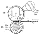
この加熱定着装置において、加熱定着部材としてのシームレス形状の定着ベルト21は加圧部材25との間で定着ニップ部26を形成している。そして、定着ベルト21の内部には、定着ベルト21を保持するために耐熱性・断熱性の樹脂あるいはセラミックによって成型された、ベルトガイド部材22が設けられており、このベルトガイド部材22と定着ベルト21の内面とが接触する位置にセラミックヒータ等の熱源23が備えられている。この熱源23はベルトガイド部材22の長手方向に沿って設けられた溝部に嵌入して固定支持されており、通電されることで発熱させる。そして、シームレス形状の定着ベルト21はベルトガイド部材22にルーズに外嵌している。加圧用剛性ステイ24はベルトガイドの22内側に挿通してある。
In this heat fixing device, a fixing
なお、加熱定着ベルト21は、ベルト基材21aの外面に弾性層21bが形成され、さらにその外面に離型層としてフッ素樹脂チューブ21cを被覆したものである。
The heat-fixing
加圧部材25は、弾性加圧ローラであり、通常、ステンレス等で製造された棒状の芯金25aにシリコーンゴム等の弾性層25bを設けて硬度を下げたもので、芯金25aの両端部を手前側と奥側のシャーシ側板(不図示)との間に回転自由に軸受けさせている。弾性加圧ローラは、表面性および離型性を向上させるために通常、表層25cとして、50μm程度のフッ素樹脂チューブが被覆されている。加圧用剛性ステイ24の両端部と装置シャーシ側のバネ受け部材(不図示)との間にそれぞれ加圧バネ(不図示)を縮設することで、加圧用剛性ステイ24には、押し下げ力が付与されている。これによってベルトガイド部材22の下面に配設したセラミックヒータ23の下面と加圧部材25の上面とが定着ベルト21を挟んで圧接して上述の定着ニップ部26が形成される。
The pressure member 25 is an elastic pressure roller, and is usually a rod-shaped cored
この定着ニップ部26に未定着トナーTによって画像が形成された被加熱体となる被記録材Pを挟持搬送させることで、トナー画像を加熱、加圧し、被記録材上に定着する。
The recording material P, which is a heated body on which an image is formed with the unfixed toner T, is nipped and conveyed in the fixing nip
以下、実施例により本発明を説明する。 Hereinafter, the present invention will be described by way of examples.
まず、以下の実施例、比較例で使用するカーボンファイバーおよび充填材を示す。 First, carbon fibers and fillers used in the following examples and comparative examples are shown.
〔充填材〕
・01M:ピッチ系カーボンファイバー、商品名:XN−100−01M、日本グラファイトファイバー(株)製、平均繊維直径D:5μm、平均繊維長L:10μm、繊維長1〜50μmのものの個数割合:100%、真密度:2.1g/cm3。
・15M:ピッチ系カーボンファイバー、商品名:XN−100−15M、日本グラファイトファイバー(株)製、平均繊維直径D:10μm、平均繊維長L:150μm、繊維長1〜50μmのものの個数割合:70%、真密度:2.2g/cm3。
・25M:ピッチ系カーボンファイバー、商品名:XN−100−25M、日本グラファイトファイバー(株)製、平均繊維直径D:10μm、平均繊維長L:250μm、繊維長1〜50μmのものの個数割合:10%、真密度:2.2g/cm3。
・A10S:高純度真球状アルミナ、商品名:アルナビーズ CB−A10S、昭和タイタニウム(株)製、重量平均粒径R:10μm。
[Filler]
・ 01M: pitch-based carbon fiber, trade name: XN-100-01M, manufactured by Nippon Graphite Fiber Co., Ltd., average fiber diameter D: 5 μm, average fiber length L: 10 μm, number ratio of fibers having a fiber length of 1-50 μm: 100 %, True density: 2.1 g / cm 3 .
15M: pitch-based carbon fiber, trade name: XN-100-15M, manufactured by Nippon Graphite Fiber Co., Ltd., average fiber diameter D: 10 μm, average fiber length L: 150 μm, number ratio of fibers having a fiber length of 1-50 μm: 70 %, True density: 2.2 g / cm 3 .
・ 25M: pitch-based carbon fiber, trade name: XN-100-25M, manufactured by Nippon Graphite Fiber Co., Ltd., average fiber diameter D: 10 μm, average fiber length L: 250 μm, number ratio of fiber length 1-50 μm: 10 %, True density: 2.2 g / cm 3 .
A10S: high-purity true spherical alumina, trade name: Aruna beads CB-A10S, manufactured by Showa Titanium Co., Ltd., weight average particle diameter R: 10 μm.
実施例1
両末端ビニル化ポリジメチルシロキサン(重量平均分子量68000(ポリスチレン換算))に対し、SiH結合を1分子中に少なくとも2個以上有する、ハイドロジェンオルガノポリシロキサンを、SiH基とビニル基が2:1の割合になるように、配合し、触媒の白金化合物を加えて、原液粘度6.5Pa・s(V型回転粘度計、ローターNo.4、60rpmにて測定)となる付加硬化型シリコーンゴム原液を得た。
Example 1
A hydrogenated organopolysiloxane having at least two SiH bonds in one molecule with respect to both ends vinylated polydimethylsiloxane (weight average molecular weight 68000 (polystyrene conversion)), having a SiH group and a vinyl group of 2: 1. Addition-curing silicone rubber stock solution having a viscosity of 6.5 Pa · s (measured with a V-type rotational viscometer, rotor No. 4, 60 rpm) by adding a platinum compound as a catalyst to a proportion. Obtained.
この付加硬化型シリコーンゴム原液に対し、ピッチ系カーボンファイバー01Mを体積比率で31.1%、およびピッチ系カーボンファイバー25Mを体積比率で8.9%の割合になるように均一に配合・混練して、シリコーンゴム組成物1を得た。このシリコーンゴム組成物1に含まれるカーボンファイバーの平均繊維直径Dは6μmであり、繊維長が1〜50μmのものの個数割合は80%であった。
This addition-curing silicone rubber stock solution is uniformly blended and kneaded so that the pitch-based carbon fiber 01M is 31.1% by volume and the pitch-based carbon fiber 25M is 8.9% by volume. Thus, a
このシリコーンゴム組成物1を、SUS304で形成されたベルト基材(厚み35μm、内径24mm)の外面にリングコート法で300μmの厚みで塗工し、200℃で4時間加熱硬化して、弾性層を形成した。さらにこの外面にPFA(テトラフルオロエチレン/パーフルオロアルキルビニルエーテル共重合体)チューブ(厚み30μm)を被覆し、両端部を切断して、長手方向の長さ230mmの加熱定着部材1を得た。
This
なお、別途、上記と同様にしてベルト基材上に弾性層を形成した。この弾性層を切り出し、厚みが6mm以上になるように複数枚を重ね合わせた状態で測定したASKER−C硬度は35度であった。また、この切り出した弾性層の厚み方向の熱伝導率も測定したところ、2.3[W/(m・K)]であった。結果を表1に示した。 Separately, an elastic layer was formed on the belt base material in the same manner as described above. The ASKER-C hardness measured in a state where the elastic layer was cut out and a plurality of layers were stacked so that the thickness was 6 mm or more was 35 degrees. Further, the thermal conductivity in the thickness direction of the cut out elastic layer was measured and found to be 2.3 [W / (m · K)]. The results are shown in Table 1.
実施例2〜9及び比較例1〜2
カーボンファイバー又は充填材として下記表1に示したものを、表1にしめす充填量で用いた以外は、実施例1と同様にして加熱定着部材2〜9(実施例)及び10、11(比較例)を作製した。シリコーンゴム組成物中のカーボンファイバーの平均繊維直径D、平均繊維長L、繊維長が1〜50μmであるものの個数割合、および加熱定着部材の弾性層のASKER−C硬度と厚み方向の熱伝導率を測定した。その結果を表1に示す。
Examples 2-9 and Comparative Examples 1-2
Heat fixing
比較例3及び4
充填材として下記表1に示したものを、表1にしめす充填量で用いた以外は、実施例1と同様にして加熱定着部材12及び13を作製した。加熱定着部材12、13に係る弾性層のASKER−C硬度と厚み方向の熱伝導率を測定した。その結果を表1に示す。
Comparative Examples 3 and 4
Heat fixing
<性能評価>
性能評価には、図3に示した加熱定着装置の定着ベルトとして上記で作製した加熱定着部材を組み込んだ加熱定着装置を、カラーレーザープリンタ(商品名:LBP−2410、キヤノン株式会社製)に組み込んだものを使用した。なお、加圧部材は外径が24mm、弾性層の厚さが3mmのものを使用した。
<Performance evaluation>
For the performance evaluation, the heat fixing device incorporating the heat fixing member produced above as a fixing belt of the heat fixing device shown in FIG. 3 is incorporated into a color laser printer (trade name: LBP-2410, manufactured by Canon Inc.). I used it. The pressurizing member used had an outer diameter of 24 mm and an elastic layer thickness of 3 mm.
加圧部材を表面の移動スピードが200mm/secとなるように、矢印の方向に回転させた状態で、セラミックヒータに通電を開始し、定着ニップ部から上流側90°の位置での加熱定着部材の外表面温度を放射型温度計(不図示)でモニターし、セラミックヒータに投入する電力のオン−オフのタイミングを調整して、外表面温度を180℃で安定させた。 In a state where the pressure member is rotated in the direction of the arrow so that the moving speed of the surface becomes 200 mm / sec, energization is started to the ceramic heater, and the heating fixing member at a position 90 ° upstream from the fixing nip portion. The external surface temperature was monitored with a radiation thermometer (not shown), and the on / off timing of the electric power supplied to the ceramic heater was adjusted to stabilize the external surface temperature at 180 ° C.
上記のプリンタを用いて、A4サイズのプリント用紙(商品名:PB PAPER GF−500、キヤノン株式会社製、68g/m2)にシアントナーとマゼンタトナーを用いてほぼ全面に100%濃度で画像を形成して、評価用画像とした。得られた画像を用いて、下記方法によって光沢度(75°グロス値)および光沢度均一性を評価した。表1にこれらの評価結果を示す。 Using the printer described above, an image was printed at 100% density on almost the entire surface using cyan toner and magenta toner on A4 size printing paper (trade name: PB PAPER GF-500, manufactured by Canon Inc., 68 g / m 2 ). An image for evaluation was formed. Using the obtained images, the glossiness (75 ° gloss value) and glossiness uniformity were evaluated by the following methods. Table 1 shows the evaluation results.
<光沢度>
日本電色株式会社製の光沢度計PG−3D(入射・反射角度=75°)を用いて、光沢度96.9の黒色ガラスを基準とし、評価画像の通紙方向先端から5cmの位置における中心部で光沢度(75°グロス値)を測定した。
<Glossiness>
Using a gloss meter PG-3D (incidence / reflection angle = 75 °) manufactured by Nippon Denshoku Co., Ltd., using black glass with a gloss level of 96.9 as a reference, at a position 5 cm from the leading edge of the evaluation image in the sheet passing direction. The glossiness (75 ° gloss value) was measured at the center.
<光沢度均一性>
5人の被験者により光沢ムラが観察されるか否かを目視で判断し、下記基準で評価した。
A:5人全員が「光沢ムラが少ない」と判断した。
B:4人が「光沢ムラが少ない」と判断した。
C:3人が「光沢ムラが少ない」と判断した。許容範囲である。
D:「光沢ムラが少ない」と判断した人数が2人以下だった。
<Glossiness uniformity>
Whether or not gloss unevenness was observed by five subjects was judged visually and evaluated according to the following criteria.
A: All five people judged that “the gloss unevenness was small”.
B: Four people judged that “the gloss unevenness was small”.
C: Three people judged that “the gloss unevenness was small”. It is an acceptable range.
D: The number of people who judged that “the gloss unevenness was small” was 2 or less.

加熱定着部材1(実施例1)では、繊維長が1〜50μmの範囲にある比較的短いカーボンファイバーが弾性層内であまり配向せずに充填され、一方、繊維長が50μm以上の比較的長いカーボンファイバーが弾性層内で長い伝熱路を形成している。これにより比較的少ない充填量で高熱伝導率が達成されており、且つ、弾性層の硬度の上昇も抑えられている。その結果、弾性層における厚み方向の熱伝導率が2.3W/(m・K)と極めて高くなり、被加熱体並びにトナー画像に対し十分に熱を供給でき、その結果、優れた光沢性能を発現している。さらに弾性層の硬度も十分に柔らかいため、被加熱体やトナー画像の表面の凹凸に追従し、被加熱体全面で極めて良好な光沢度の均一性が確保できた。 In the heat fixing member 1 (Example 1), relatively short carbon fibers having a fiber length in the range of 1 to 50 μm are filled without being oriented in the elastic layer, while the fiber length is relatively long such as 50 μm or more. The carbon fiber forms a long heat transfer path in the elastic layer. As a result, a high thermal conductivity is achieved with a relatively small filling amount, and an increase in the hardness of the elastic layer is also suppressed. As a result, the thermal conductivity in the thickness direction of the elastic layer is as extremely high as 2.3 W / (m · K), and sufficient heat can be supplied to the object to be heated and the toner image, resulting in excellent gloss performance. It is expressed. Furthermore, since the hardness of the elastic layer is sufficiently soft, it follows the unevenness of the surface of the heated object and the toner image, and an extremely good gloss uniformity can be secured over the entire surface of the heated object.
加熱定着部材2(実施例2)では、カーボンファイバーの繊維長の分布はそのままにして、配合量を半分にして、加熱定着部材1に較べ、弾性層の柔軟性を向上させたものである。弾性層の厚み方向の熱伝導率は1.2W/(m・K)と十分であり、光沢性能、特に光沢度均一性について極めて良好な結果が得られた。
In the heat fixing member 2 (Example 2), the fiber length distribution of the carbon fiber is kept as it is, and the blending amount is halved to improve the flexibility of the elastic layer compared to the
加熱定着部材3(実施例3)では、弾性層の厚み方向の熱伝導率が1.5W/(m・K)であり、ASKER−C硬度も27度と柔軟で、十分な光沢性能と極めて良好な光沢度均一性を得た。 In the heat fixing member 3 (Example 3), the thermal conductivity in the thickness direction of the elastic layer is 1.5 W / (m · K), the ASKER-C hardness is flexible at 27 degrees, and the gloss performance is extremely high. Good gloss uniformity was obtained.
加熱定着部材4(実施例4)では、弾性層の厚み方向の熱伝導率が2.0W/(m・K)と極めて高く、十分な柔軟性を有する結果、優れた光沢性能と極めて良好な光沢度均一性を確保できた。 In the heat fixing member 4 (Example 4), the thermal conductivity in the thickness direction of the elastic layer is as extremely high as 2.0 W / (m · K), and as a result of sufficient flexibility, excellent gloss performance and extremely good Gloss uniformity was secured.
加熱定着部材5(実施例5)では、加熱定着部材4には及ばなかったものの十分に優れた光沢性能が得られ、極めて良好な光沢度均一性が得られた。 Although the heat fixing member 5 (Example 5) did not reach the heat fixing member 4, a sufficiently excellent gloss performance was obtained, and extremely good gloss uniformity was obtained.
加熱定着部材6(実施例6)では、繊維長が1〜50μmの範囲にあるものが100%と比較的短いもののみからなるカーボンファイバーを用いた結果、使用した量が少ないにもかかわらず、弾性層の柔軟性が加熱定着部材1〜5程にならなかったものの、良好な結果であった。
In the heat fixing member 6 (Example 6), as a result of using carbon fibers having only a relatively short fiber length in the range of 1 to 50 μm, although the amount used is small, Although the flexibility of the elastic layer was not as high as that of the
加熱定着部材7(実施例7)では、加熱定着部材6に比して弾性層中のカーボンファイバーの充填量を減少させ、弾性層の低硬度化を図り、極めて良好な光沢度均一性を達成した。 In the heat fixing member 7 (Example 7), the filling amount of the carbon fiber in the elastic layer is reduced as compared with the heat fixing member 6, the hardness of the elastic layer is reduced, and extremely good gloss uniformity is achieved. did.
加熱定着部材8(実施例8)および加熱定着部材9(実施例9)でも、弾性層中にカーボンファイバーを配合することにより、厚み方向の熱伝導率1.0W/(m・K)以上を確保し、良好な光沢性能を確保しつつも許容範囲内の光沢度均一性を確保している。 Also in the heat fixing member 8 (Example 8) and the heat fixing member 9 (Example 9), the thermal conductivity in the thickness direction is 1.0 W / (m · K) or more by blending the carbon fiber in the elastic layer. It ensures the gloss uniformity within the allowable range while ensuring good gloss performance.
一方、加熱定着部材10(比較例1)および加熱定着部材11(比較例2)では、弾性層中に熱流路となるカーボンファイバーの添加量が少ないため、厚み方向の熱伝導率が十分確保されておらず、その結果、十分な光沢性能を確保することができなかった。 On the other hand, in the heat-fixing member 10 (Comparative Example 1) and the heat-fixing member 11 (Comparative Example 2), the amount of carbon fiber to be a heat flow path in the elastic layer is small, so that sufficient heat conductivity in the thickness direction is ensured. As a result, sufficient gloss performance could not be secured.
また、比較例3で作成した加熱定着部材12を用いた場合には、所望の光沢性能を得るため、弾性層にアルミナ粒子を50%の充填割合で添加したものであるが、硬度が高くなりすぎたため、被加熱体やトナー画像の表面の凹凸に追従できず、光沢ムラが発生してしまった。
Further, when the
さらに、加熱定着部材13(比較例4)では、弾性層におけるアルミナ粒子の充填割合を30%と減少させて低硬度化をはかり、光沢ムラの低減を試みたものであるが、充填量を減らしたことに伴い熱伝導率が低下したため、十分な光沢性能を確保することができなかった。 Further, in the heat fixing member 13 (Comparative Example 4), the filling ratio of the alumina particles in the elastic layer is reduced to 30% to reduce the hardness, and the reduction of gloss unevenness is attempted. As a result, the thermal conductivity decreased, so that sufficient gloss performance could not be secured.
以下の実施例、比較例で使用するカーボンファイバーおよび配向阻害成分を示す。 The carbon fibers and orientation-inhibiting components used in the following examples and comparative examples are shown.
〔カーボンファイバー〕
・25M:ピッチ系カーボンファイバー、商品名:XN−100−25M、日本グラファイトファイバー(株)製、平均繊維直径D:10μm、平均繊維長L:250μm、繊維長1〜50μmのものの個数割合:10%、真密度:2.2g/cm3。
・15M:ピッチ系カーボンファイバー、商品名:XN−100−15M、日本グラファイトファイバー(株)製、平均繊維直径D:10μm、平均繊維長L:150μm、繊維長1〜50μmのものの個数割合:70%、真密度:2.2g/cm3。
・10M:ピッチ系カーボンファイバー、商品名:XN−100−10M、日本グラファイトファイバー(株)製、平均繊維直径D:10μm、平均繊維長L:100μm、繊維長1〜50μmのものの個数割合:80%、真密度:2.2g/cm3。
・05M:ピッチ系カーボンファイバー、商品名:XN−100−05M、日本グラファイトファイバー(株)製、平均繊維直径D:10μm、平均繊維長L:50μm、繊維長1〜50μmのものの個数割合:90%、真密度:2.2g/cm3。
・01M分級:ピッチ系カーボンファイバー(商品名:XN−100−01M、日本グラファイトファイバー(株)製、平均繊維直径D:5μm、平均繊維長L:10μm、繊維長1〜50μmのものの個数割合:100%、真密度:2.1g/cm3)を分級して得た、平均繊維直径D:3μm、平均繊維長L:5μm、繊維長1〜50μmのものの個数割合:100%、真密度2.1g/cm3。
[Carbon fiber]
・ 25M: pitch-based carbon fiber, trade name: XN-100-25M, manufactured by Nippon Graphite Fiber Co., Ltd., average fiber diameter D: 10 μm, average fiber length L: 250 μm, number ratio of fiber length 1-50 μm: 10 %, True density: 2.2 g / cm 3 .
15M: pitch-based carbon fiber, trade name: XN-100-15M, manufactured by Nippon Graphite Fiber Co., Ltd., average fiber diameter D: 10 μm, average fiber length L: 150 μm, number ratio of fibers having a fiber length of 1-50 μm: 70 %, True density: 2.2 g / cm 3 .
10M: pitch-based carbon fiber, trade name: XN-100-10M, manufactured by Nippon Graphite Fiber Co., Ltd., average fiber diameter D: 10 μm, average fiber length L: 100 μm, number ratio of fibers having a fiber length of 1-50 μm: 80 %, True density: 2.2 g / cm 3 .
・ 05M: pitch-based carbon fiber, trade name: XN-100-05M, manufactured by Nippon Graphite Fiber Co., Ltd., average fiber diameter D: 10 μm, average fiber length L: 50 μm, number ratio of fibers having a fiber length of 1-50 μm: 90 %, True density: 2.2 g / cm 3 .
・ 01M classification: Pitch-based carbon fiber (trade name: XN-100-01M, manufactured by Nippon Graphite Fiber Co., Ltd., average fiber diameter D: 5 μm, average fiber length L: 10 μm, number ratio of fiber length 1-50 μm: 100%, true density: 2.1 g / cm 3 ), average fiber diameter D: 3 μm, average fiber length L: 5 μm, number ratio of fiber length 1-50 μm: 100%,
〔配向阻害成分〕
・A50S:酸化アルミニウム粒子、商品名:高純度真球状アルミナ・アルナビーズ CB−A50S、昭和タイタニウム(株)製、重量平均粒径R:50μm。
・A30S:酸化アルミニウム粒子、商品名:高純度真球状アルミナ・アルナビーズ CB−A30S、昭和タイタニウム(株)製、重量平均粒径R:30μm。
・A10S:酸化アルミニウム粒子、商品名:高純度真球状アルミナ・アルナビーズ CB−A10S、昭和タイタニウム(株)製、重量平均粒径R:10μm。
・A50S分級:酸化アルミニウム粒子A50Sを分級して得た重量平均粒径R:45μmのもの。
・A10分級:酸化アルミニウム粒子(商品名:高純度真球状アルミナ・アルナビーズ CB−A10、昭和タイタニウム(株)製、重量平均粒径R:10μm)を分級して得た重量平均粒径R:5μmのもの。
・A05S分級3:酸化アルミニウム粒子(商品名:高純度真球状アルミナ・アルナビーズ CB−A05S、昭和タイタニウム(株)製、重量平均粒径R:3μm)を分級して得た重量平均粒径R:3μmのもの。
・A05S分級2:酸化アルミニウム粒子(商品名:高純度真球状アルミナ・アルナビーズ CB−A05S、昭和タイタニウム(株)製、重量平均粒径R:3μm)を分級して得た重量平均粒径R:2μmのもの。
・WZ:酸化亜鉛ウィスカー、商品名:パナテトラ WZ−0501、松下アムテック(株)製、重量平均粒径R:25μm。
(Orientation-inhibiting component)
A50S: Aluminum oxide particles, trade name: high-purity true spherical alumina Aruna beads CB-A50S, manufactured by Showa Titanium Co., Ltd., weight average particle size R: 50 μm.
A30S: Aluminum oxide particles, trade name: high-purity spherical alumina, Aruna beads CB-A30S, manufactured by Showa Titanium Co., Ltd., weight average particle size R: 30 μm.
A10S: Aluminum oxide particles, trade name: high purity spherical alumina, Aruna beads CB-A10S, manufactured by Showa Titanium Co., Ltd., weight average particle size R: 10 μm.
A50S classification: weight average particle diameter R: 45 μm obtained by classifying aluminum oxide particles A50S.
A10 classification: Aluminum oxide particles (trade name: high-purity spherical alumina, Aruna beads CB-A10, manufactured by Showa Titanium Co., Ltd., weight average particle diameter R: 10 μm), and weight average particle diameter R: 5 μm Things.
A05S classification 3: Aluminum oxide particles (trade name: high-purity spherical alumina, Aruna beads CB-A05S, manufactured by Showa Titanium Co., Ltd., weight average particle size R: 3 μm) 3 μm.
A05S classification 2: Aluminum oxide particles (trade name: High-purity spherical alumina Aluna beads CB-A05S, Showa Titanium Co., Ltd., weight average particle size R: 3 μm) 2 μm.
WZ: Zinc oxide whisker, trade name: Panatetra WZ-0501, manufactured by Matsushita Amtec Co., Ltd., weight average particle size R: 25 μm.
実施例10
両末端ビニル化ポリジメチルシロキサン(重量平均分子量68000(ポリスチレン換算))に対し、SiH結合を1分子中に少なくとも2個以上有する、ハイドロジェンオルガノポリシロキサンを、SiH基とビニル基が2:1の割合になるように、配合し、触媒の白金化合物を加えて、原液粘度6.5Pa・s(V型回転粘度計、ローターNo.4、60rpmにて測定)となる付加硬化型シリコーンゴム原液を得た。
Example 10
A hydrogenated organopolysiloxane having at least two SiH bonds in one molecule with respect to both ends vinylated polydimethylsiloxane (weight average molecular weight 68000 (polystyrene conversion)), having a SiH group and a vinyl group of 2: 1. Addition-curing silicone rubber stock solution having a viscosity of 6.5 Pa · s (measured with a V-type rotational viscometer, rotor No. 4, 60 rpm) by adding a platinum compound as a catalyst to a proportion. Obtained.
この付加硬化型シリコーンゴム原液に対し、カーボンファイバー15Mを体積比率で30%、さらに、酸化アルミニウム粒子A50Sを体積比率で20%の割合になるように均一に配合し、混練して、シリコーンゴム組成物を得た。 To this addition curable silicone rubber stock solution, the carbon fiber 15M is uniformly blended so that the volume ratio is 30% and the aluminum oxide particles A50S are 20% in volume ratio, and kneaded to form a silicone rubber composition. I got a thing.
このシリコーンゴム組成物を、SUS304で形成されたベルト基材(厚み35μm、内径24mm)の外面にリングコート法で300μmの厚みで塗工し、200℃で4時間加熱硬化して、弾性層を形成した。さらにこの外面にPFA(テトラフルオロエチレン/パーフルオロアルキルビニルエーテル共重合体)チューブ(厚み30μm)を被覆し、両端部を切断して、長さ230mmの加熱定着部材15を得た。
This silicone rubber composition was applied to the outer surface of a belt base material (thickness 35 μm,
なお、別途上記同様にしてベルト基材上に弾性層を形成し、フッ素樹脂チューブを重ねる前の加熱定着部材を作製し、弾性層を切り出し、厚みが6mm以上になるように複数枚を重ね合わせた状態で測定したASKER−C硬度は39度であった。また、この切り出した弾性層の厚み方向の熱伝導率も測定したところ、2.2[W/(m・K)]であった。結果を表2に示した。 Separately, an elastic layer is formed on the belt base material in the same manner as described above, a heat fixing member before the fluororesin tube is stacked is produced, the elastic layer is cut out, and a plurality of sheets are stacked so that the thickness is 6 mm or more. The ASKER-C hardness measured in the above state was 39 degrees. Further, the thermal conductivity in the thickness direction of the cut out elastic layer was measured and found to be 2.2 [W / (m · K)]. The results are shown in Table 2.
実施例11〜16、比較例5〜8
カーボンファイバーおよび配向阻害成分として表2に示したものを表2に示す量配合した以外は、実施例10と同様にして、シリコーンゴム組成物を調製し、さらに加熱定着部材16〜25を作成した。これらの加熱定着部材の弾性層のASKER−C硬度および熱伝導率も測定し、それらを表2に示した。
Examples 11-16, Comparative Examples 5-8
A silicone rubber composition was prepared in the same manner as in Example 10 except that the amount shown in Table 2 was added as the carbon fiber and the orientation-inhibiting component, and the heat fixing members 16 to 25 were prepared. . The ASKER-C hardness and thermal conductivity of the elastic layer of these heat fixing members were also measured and are shown in Table 2.
上記の実施例10〜16及び比較例5〜8の加熱定着部材に関して、実施例1と同様にして評価を行った。評価結果を表2に示す。 The heat fixing members of Examples 10 to 16 and Comparative Examples 5 to 8 were evaluated in the same manner as in Example 1. The evaluation results are shown in Table 2.
加熱定着部材15(実施例10)では、カーボンファイバーおよびアルミナ粒子の配合および繊維直径と粒径との関係(R/D=5)が適正であり、アルミナ粒子がカーボンファイバーの配向を効果的に抑制し、弾性層の厚み方向の熱伝導率が2.2W/(m・K)と極めて高くなったと考えられる。これにより、被加熱体およびトナーに対し十分に熱を供給でき、その結果、優れた光沢性能を発現することができた。また、弾性層も硬度が小さく、十分に柔らかいため、被加熱体やトナー画像の表面の凹凸に追従し、その結果、被加熱体全面で極めて良好な光沢度均一性が確保できたことがわかった。 In the heat fixing member 15 (Example 10), the composition of the carbon fiber and the alumina particles and the relationship between the fiber diameter and the particle size (R / D = 5) are appropriate, and the alumina particles effectively adjust the orientation of the carbon fibers. It is considered that the thermal conductivity in the thickness direction of the elastic layer was extremely high at 2.2 W / (m · K). As a result, heat could be sufficiently supplied to the heated object and the toner, and as a result, excellent gloss performance could be exhibited. In addition, the elastic layer has low hardness and is soft enough to follow the unevenness of the surface of the heated object or toner image, and as a result, it was found that extremely good gloss uniformity was ensured over the entire surface of the heated object. It was.
加熱定着部材16(実施例11)では、カーボンファイバーおよびアルミナ粒子の形状および合計の体積充填率は加熱定着部材15と同じではあるが、配合割合を変更した結果、厚み方向の熱伝導率は2.1W/(m・K)と十分に高くなり、光沢性能についても優れたレベルであり、弾性層も十分に柔らかく、被加熱体全面での光沢度均一性も極めて良好であった。
In the heat fixing member 16 (Example 11), the shape and the total volume filling rate of the carbon fibers and the alumina particles are the same as those of the
加熱定着部材17(実施例12)では、R/D=3の関係にあるアルミナ粒子とカーボンファイバーを上記のように配合しているので、若干厚み方向の熱伝導率(1.4W/(m・K))が小さくなったが、ASKER−C硬度は35度であり、得られた画像も十分に優れた光沢性能が達成され、極めて良好な光沢度均一性を得ている。 In the heat fixing member 17 (Example 12), since the alumina particles and the carbon fibers having the relationship of R / D = 3 are blended as described above, the thermal conductivity (1.4 W / (m Although K)) was reduced, the ASKER-C hardness was 35 degrees, and the obtained image also achieved a sufficiently excellent gloss performance and obtained extremely good gloss uniformity.
加熱定着部材18(実施例13)では、R/D=1の関係にあるアルミナ粒子とカーボンファイバーを表2のように配合しているので、熱伝導を担保する充填材がすくなくなり、厚み方向の熱伝導率が1.0W/(m・K)とやや小さくなったが、ASKER−C硬度は30度と十分に小さく、熱伝導性と柔軟性の関係から、優れた光沢性能と極めて良好な光沢度均一性を確保できている。 In the heat fixing member 18 (Example 13), the alumina particles and the carbon fibers having a relationship of R / D = 1 are blended as shown in Table 2, so that the filler for ensuring heat conduction is reduced and the thickness direction is reduced. Although the thermal conductivity of AW was slightly reduced to 1.0 W / (m · K), the ASKER-C hardness was as small as 30 degrees, and excellent gloss performance and extremely good due to the relationship between thermal conductivity and flexibility High gloss uniformity.
加熱定着部材19(比較例5)および加熱定着部材20(比較例6)では、いずれも厚み方向の熱伝導率が所望の値に達しなかった。また、光沢性能に関しても低下した。 In both the heat fixing member 19 (Comparative Example 5) and the heat fixing member 20 (Comparative Example 6), the thermal conductivity in the thickness direction did not reach a desired value. Also, the gloss performance was lowered.
加熱定着部材21(実施例14)は、配合したカーボンファイバーとアルミナ粒子が望ましい関係(0.5≦R/D≦10)から外れた範囲(R/D=0.3)にあるものを用いたので、アルミナ粒子とシリコーンゴムとの界面面積が増加し、その結果、弾性層の柔軟性が加熱定着部材15〜20に及ばなかった。しかし、熱伝導率が高いため、光沢性能については優れた結果が得られ、光沢度均一性評価においても許容内であった。 As the heat fixing member 21 (Example 14), one in which the blended carbon fiber and the alumina particles are out of the desired relationship (0.5 ≦ R / D ≦ 10) (R / D = 0.3) is used. As a result, the interface area between the alumina particles and the silicone rubber increased, and as a result, the flexibility of the elastic layer did not reach the heat fixing members 15-20. However, since the thermal conductivity was high, excellent results were obtained for the gloss performance, and the gloss uniformity evaluation was acceptable.
加熱定着部材22(実施例15)おいても、R/D=15と、カーボンファイバーとアルミナ粒子が望ましい関係(0.5≦R/D≦10)から外れた範囲にあり、カーボンファイバーとシリコーンゴムの界面面積が増加し、その結果、弾性層の柔軟性が加熱定着部材15〜20に及ばなかった。しかし、光沢性能については十分なレベルであり、光沢度均一性評価においても許容内であった。 Also in the heat fixing member 22 (Example 15), R / D = 15, and the carbon fiber and the alumina particles are out of the desired relationship (0.5 ≦ R / D ≦ 10). The interfacial area of the rubber increased, and as a result, the flexibility of the elastic layer did not reach the heat fixing members 15-20. However, the gloss performance was at a sufficient level, and was also acceptable in the gloss uniformity evaluation.
加熱定着部材23(比較例7)および加熱定着部材24(比較例8)を用いた場合においても、カーボンファイバーとアルミナ粒子の関係が0.5≦R/D≦10から外れた範囲にあり、表2のように配合することによって、弾性層の熱伝導率が所望の値に達しなかった。また、光沢性能に関しても低下した。 Even in the case of using the heat fixing member 23 (Comparative Example 7) and the heat fixing member 24 (Comparative Example 8), the relationship between the carbon fiber and the alumina particles is in a range outside 0.5 ≦ R / D ≦ 10. By blending as shown in Table 2, the thermal conductivity of the elastic layer did not reach the desired value. Also, the gloss performance was lowered.
加熱定着部材25(実施例16)では、カーボンファイバー配向阻害成分として、テトラポット形状の酸化亜鉛ウィスカー(WZ)を用いたが、弾性層の熱伝導率および柔軟性は所望のレベルを確保し、十分に優れた光沢性能と良好な光沢度均一性を実現している。 In the heat fixing member 25 (Example 16), a zinc pot whisker (WZ) having a tetrapot shape was used as a carbon fiber orientation-inhibiting component. However, the thermal conductivity and flexibility of the elastic layer ensure a desired level, Realizes excellent gloss performance and good gloss uniformity.
以上、実施例、比較例に見られるように、カーボンファイバーを配合し、厚み方向の熱伝導率が1.0W/(m・K)以上である弾性層を有するシームレスタイプの加熱定着部材は、加熱定着装置の加熱定着部材として、高速プリント時における定着画像の高い光沢性能を確保しつつ、良好な画像均一性を達成できる。 As described above, as seen in Examples and Comparative Examples, a seamless type heat fixing member having an elastic layer containing carbon fiber and having a thermal conductivity in the thickness direction of 1.0 W / (m · K) or more is As a heat fixing member of the heat fixing device, it is possible to achieve good image uniformity while ensuring high gloss performance of a fixed image during high-speed printing.
更には、カーボンファイバーの配合を調整することで、より高い熱伝導性を有し、且つ、より低硬度の弾性層を設計することが可能となり、優れた光沢性能と画像均一性を同時に達成できる加熱定着装置を得ることができる。 Furthermore, by adjusting the blending of carbon fibers, it becomes possible to design an elastic layer with higher thermal conductivity and lower hardness, and can achieve excellent gloss performance and image uniformity at the same time. A heat fixing device can be obtained.
また、カーボンファイバーと共に配向阻害成分を配合させて、カーボンファイバーの配向を阻害することにより、さらに良好な光沢性能を有する画像が得られる加熱定着装置を得ることができる。 Further, by blending an orientation-inhibiting component together with the carbon fiber to inhibit the orientation of the carbon fiber, it is possible to obtain a heat-fixing apparatus that can obtain an image having even better gloss performance.
1 基材
2 弾性層
2a 耐熱性弾性材料
2b カーボンファイバー
2c 配向阻害成分
3 表層(離型層)
11 定着ローラ
12 加圧ローラ
13 加熱ヒータ
14 金属製芯金
15 弾性層
21 定着ベルト
21a ベルト基材
21b 弾性層
21c フッ素樹脂チューブ
22 ベルトガイド部材
23 熱源(セラミックヒータ)
24 加圧用剛性ステイ
25 加圧部材
25a ステンレス芯金
25b シリコーンゴム弾性層
25c 表層
26 定着ニップ部
T 未定着トナー
P 被記録材
DESCRIPTION OF
DESCRIPTION OF
24 Pressurizing rigid stay 25
Claims (13)
該弾性層は、弾性材料、及び、該弾性材料に分散されているカーボンファイバー並びに配向阻害成分を含み、The elastic layer includes an elastic material, a carbon fiber dispersed in the elastic material, and an orientation-inhibiting component,
該カーボンファイバーの該弾性層の面方向への配向が、該配向阻害成分によって阻害されており、The orientation of the carbon fiber in the plane direction of the elastic layer is inhibited by the orientation-inhibiting component,
該配向阻害成分が、粒子であり、その重量平均粒径をR(μm)とするとき、重量平均粒径R(μm)とカーボンファイバーの平均繊維直径D(μm)との関係が、When the orientation-inhibiting component is particles and the weight average particle diameter is R (μm), the relationship between the weight average particle diameter R (μm) and the average fiber diameter D (μm) of the carbon fiber is:
0.5≦R/D≦100.5 ≦ R / D ≦ 10
を満たし、The filling,
かつ、該弾性層の厚み方向の熱伝導率が、1.0W/(m・K)以上であることを特徴とする加熱定着部材。A heat fixing member having a thermal conductivity in the thickness direction of the elastic layer of 1.0 W / (m · K) or more.
Priority Applications (1)
| Application Number | Priority Date | Filing Date | Title |
|---|---|---|---|
| JP2006040102A JP4911674B2 (en) | 2005-02-21 | 2006-02-17 | Heat fixing member and heat fixing device |
Applications Claiming Priority (5)
| Application Number | Priority Date | Filing Date | Title |
|---|---|---|---|
| JP2005043984 | 2005-02-21 | ||
| JP2005043984 | 2005-02-21 | ||
| JP2005043905 | 2005-02-21 | ||
| JP2005043905 | 2005-02-21 | ||
| JP2006040102A JP4911674B2 (en) | 2005-02-21 | 2006-02-17 | Heat fixing member and heat fixing device |
Publications (3)
| Publication Number | Publication Date |
|---|---|
| JP2006259712A JP2006259712A (en) | 2006-09-28 |
| JP2006259712A5 JP2006259712A5 (en) | 2008-12-04 |
| JP4911674B2 true JP4911674B2 (en) | 2012-04-04 |
Family
ID=37098979
Family Applications (1)
| Application Number | Title | Priority Date | Filing Date |
|---|---|---|---|
| JP2006040102A Expired - Fee Related JP4911674B2 (en) | 2005-02-21 | 2006-02-17 | Heat fixing member and heat fixing device |
Country Status (1)
| Country | Link |
|---|---|
| JP (1) | JP4911674B2 (en) |
Families Citing this family (18)
| Publication number | Priority date | Publication date | Assignee | Title |
|---|---|---|---|---|
| JP5171030B2 (en) * | 2006-12-28 | 2013-03-27 | キヤノン株式会社 | Heating rotator, method of manufacturing the heating rotator, and image heating apparatus having the heating rotator |
| JP5072381B2 (en) * | 2007-02-07 | 2012-11-14 | 株式会社リコー | Fixing apparatus and image forming apparatus |
| JP5926473B2 (en) * | 2008-09-10 | 2016-05-25 | 住友電気工業株式会社 | Fixing belt |
| JP5414450B2 (en) * | 2009-10-19 | 2014-02-12 | キヤノン株式会社 | Pressure member, image heating apparatus, and image forming apparatus |
| JP5639488B2 (en) * | 2011-01-24 | 2014-12-10 | キヤノン株式会社 | Image heating device |
| RU2611084C2 (en) * | 2012-12-19 | 2017-02-21 | Кэнон Кабусики Кайся | Electrophotographic fixing element, fixing device and electrophotographic image forming device |
| WO2014103263A1 (en) | 2012-12-26 | 2014-07-03 | キヤノン株式会社 | Adhesion device and electrophotographic image forming device |
| JP6136636B2 (en) * | 2013-06-26 | 2017-05-31 | 株式会社リコー | PRESSURE ROLLER, FIXING DEVICE AND IMAGE FORMING DEVICE EQUIPPED WITH THE SAME |
| JP6357875B2 (en) | 2013-07-26 | 2018-07-18 | 株式会社リコー | Fixing member, fixing device, and image forming apparatus |
| JP6201726B2 (en) * | 2013-12-19 | 2017-09-27 | 富士ゼロックス株式会社 | Resin base material, endless belt, fixing device, and image forming apparatus |
| JP2016102881A (en) * | 2014-11-28 | 2016-06-02 | 住友理工株式会社 | Roll for electrophotographic apparatus and manufacturing method thereof |
| JP6753745B2 (en) * | 2016-09-12 | 2020-09-09 | デクセリアルズ株式会社 | Heat conduction sheet and semiconductor device |
| JP7073110B2 (en) * | 2017-01-30 | 2022-05-23 | キヤノン株式会社 | Additive-curing liquid silicone rubber mixture, electrophotographic components and their manufacturing methods, and fixing devices |
| JP6976838B2 (en) * | 2017-01-30 | 2021-12-08 | キヤノン株式会社 | Additive-curing liquid silicone rubber mixture, electrophotographic components and their manufacturing methods, and fixing devices |
| JP7321771B2 (en) | 2018-06-07 | 2023-08-07 | キヤノン株式会社 | Fixing member and heat fixing device |
| JP7114351B2 (en) | 2018-06-07 | 2022-08-08 | キヤノン株式会社 | Fixing member and heat fixing device |
| JP7234790B2 (en) * | 2019-05-16 | 2023-03-08 | コニカミノルタ株式会社 | Fixing device and image forming device |
| JP2020194156A (en) | 2019-05-23 | 2020-12-03 | キヤノン株式会社 | Fixing member, fixing device, and image forming apparatus |
Family Cites Families (7)
| Publication number | Priority date | Publication date | Assignee | Title |
|---|---|---|---|---|
| JPS5499640A (en) * | 1978-01-24 | 1979-08-06 | Ricoh Co Ltd | Fixing roll |
| US6002910A (en) * | 1998-06-29 | 1999-12-14 | Xerox Corporation | Heated fuser member with elastomer and anisotropic filler coating |
| JP2002268423A (en) * | 2001-01-05 | 2002-09-18 | Ricoh Co Ltd | Fixing belt and image forming device having the same |
| JP2002351243A (en) * | 2001-05-23 | 2002-12-06 | Canon Inc | Fixing device and image forming device |
| JP2004184517A (en) * | 2002-11-29 | 2004-07-02 | Canon Inc | Heating device |
| JP2004347904A (en) * | 2003-05-23 | 2004-12-09 | Kyocera Mita Corp | Fixing device |
| JP2005292218A (en) * | 2004-03-31 | 2005-10-20 | Arai Pump Mfg Co Ltd | Fixing roller |
-
2006
- 2006-02-17 JP JP2006040102A patent/JP4911674B2/en not_active Expired - Fee Related
Also Published As
| Publication number | Publication date |
|---|---|
| JP2006259712A (en) | 2006-09-28 |
Similar Documents
| Publication | Publication Date | Title |
|---|---|---|
| JP4911674B2 (en) | Heat fixing member and heat fixing device | |
| US7457577B2 (en) | Heat fixing member and heat fixing assembly | |
| JP6173040B2 (en) | Fixing belt and fixing device | |
| EP2937737B1 (en) | Electrophotographic fixing member, fixing apparatus and electrophotographic image forming apparatus | |
| JP5013700B2 (en) | Image heating device | |
| WO2014103252A1 (en) | Electrophotographic adhesion member, adhesion device, and electrophotographic image forming device | |
| JP6429533B2 (en) | Electrophotographic fixing member, fixing device, and electrophotographic image forming apparatus | |
| JP6061606B2 (en) | Heating belt and heating device | |
| JP5178290B2 (en) | Image heating apparatus and rotatable heating member used in the apparatus | |
| JP2013214109A (en) | Pressure member and image heating apparatus with pressure member | |
| US8606164B2 (en) | Rotatable image heating member and image heating device | |
| JP6366662B2 (en) | Fixing member, fixing device, image forming apparatus, and fixing member manufacturing method | |
| JP4307289B2 (en) | Heat fixing member and heat fixing device | |
| JP2005037829A (en) | Circulation body and fixing device | |
| JP5054924B2 (en) | Fixing member | |
| JP2019028184A (en) | Fixing member and method for manufacturing fixing member | |
| JP7476040B2 (en) | Fixing device | |
| JP5037049B2 (en) | Elastic member, fixing member, fixing device, and image forming apparatus | |
| JP2007171280A (en) | Seamless cylindrical member and fixing device | |
| JP2022042562A (en) | Fixing device | |
| JP2022042561A (en) | Fixing belt and method for manufacturing fixing belt | |
| JP2023019045A (en) | Fixing member and heat fixing device | |
| JP2004163578A (en) | Fixing member | |
| JP2022169436A (en) | Fixing belt and fixing device | |
| JP2023019044A (en) | Fixing belt and fixing device |
Legal Events
| Date | Code | Title | Description |
|---|---|---|---|
| A521 | Request for written amendment filed |
Free format text: JAPANESE INTERMEDIATE CODE: A523 Effective date: 20081021 |
|
| A621 | Written request for application examination |
Free format text: JAPANESE INTERMEDIATE CODE: A621 Effective date: 20081021 |
|
| RD04 | Notification of resignation of power of attorney |
Free format text: JAPANESE INTERMEDIATE CODE: A7424 Effective date: 20100617 |
|
| RD05 | Notification of revocation of power of attorney |
Free format text: JAPANESE INTERMEDIATE CODE: A7425 Effective date: 20100730 |
|
| RD04 | Notification of resignation of power of attorney |
Free format text: JAPANESE INTERMEDIATE CODE: A7424 Effective date: 20101227 |
|
| A977 | Report on retrieval |
Free format text: JAPANESE INTERMEDIATE CODE: A971007 Effective date: 20111014 |
|
| A131 | Notification of reasons for refusal |
Free format text: JAPANESE INTERMEDIATE CODE: A131 Effective date: 20111019 |
|
| A521 | Request for written amendment filed |
Free format text: JAPANESE INTERMEDIATE CODE: A523 Effective date: 20111219 |
|
| TRDD | Decision of grant or rejection written | ||
| A01 | Written decision to grant a patent or to grant a registration (utility model) |
Free format text: JAPANESE INTERMEDIATE CODE: A01 Effective date: 20120111 |
|
| A01 | Written decision to grant a patent or to grant a registration (utility model) |
Free format text: JAPANESE INTERMEDIATE CODE: A01 |
|
| A61 | First payment of annual fees (during grant procedure) |
Free format text: JAPANESE INTERMEDIATE CODE: A61 Effective date: 20120113 |
|
| R151 | Written notification of patent or utility model registration |
Ref document number: 4911674 Country of ref document: JP Free format text: JAPANESE INTERMEDIATE CODE: R151 |
|
| FPAY | Renewal fee payment (event date is renewal date of database) |
Free format text: PAYMENT UNTIL: 20150127 Year of fee payment: 3 |
|
| LAPS | Cancellation because of no payment of annual fees |