JP4909703B2 - projector - Google Patents
projector Download PDFInfo
- Publication number
- JP4909703B2 JP4909703B2 JP2006278636A JP2006278636A JP4909703B2 JP 4909703 B2 JP4909703 B2 JP 4909703B2 JP 2006278636 A JP2006278636 A JP 2006278636A JP 2006278636 A JP2006278636 A JP 2006278636A JP 4909703 B2 JP4909703 B2 JP 4909703B2
- Authority
- JP
- Japan
- Prior art keywords
- light
- light source
- guide member
- projector
- polarizing plate
- Prior art date
- Legal status (The legal status is an assumption and is not a legal conclusion. Google has not performed a legal analysis and makes no representation as to the accuracy of the status listed.)
- Expired - Fee Related
Links
Images


Description
本発明はプロジェクタに関し、特に単板型の液晶プロジェクタの照明光学系を用いるプロジェクタに関する。 The present invention relates to a projector, and more particularly to a projector using an illumination optical system of a single plate type liquid crystal projector.
従来から、投射型表示装置であるプロジェクタとして、角柱状の導光部材の入射端に光源を配置して、この導光部材の出射端側には画像形成素子である液晶パネルを配置し、導光部材から出射する光を直接液晶パネルに入射させる照明光学系を有するプロジェクタが知られている。 Conventionally, as a projector that is a projection display device, a light source is disposed at the incident end of a prismatic light guide member, and a liquid crystal panel that is an image forming element is disposed at the exit end side of the light guide member. A projector having an illumination optical system that directly enters light emitted from an optical member into a liquid crystal panel is known.
液晶パネルを表示素子に用いるプロジェクタにおいては、光源が放電ランプであっても発光ダイオードであっても、非偏光を発する光源を使う限り、光利用効率を高めるためにどちらか一方の直線偏光光に統一するための偏光変換を実施することが行われている。また、偏光変換と同時に、投射画像の輝度の均一性の確保も非常に重要なので、偏光変換と輝度均一化を両立させることが必要であった。 In a projector using a liquid crystal panel as a display element, regardless of whether the light source is a discharge lamp or a light emitting diode, as long as a non-polarized light source is used, either one of the linearly polarized light is used to increase the light use efficiency. The polarization conversion for unifying is performed. In addition, since it is very important to ensure the uniformity of the brightness of the projected image simultaneously with the polarization conversion, it is necessary to achieve both the polarization conversion and the brightness uniformity.
この両立を果たすことのできる構成としては、放電ランプ(白色の非偏光光)と、フライアイレンズと、そしてフラットPBS(偏光ビームスプリッター)とを用いる構成が、セイコーエプソン社により確立されて、現在の液晶プロジェクタにおける最先端の技術として認められている。 As a configuration that can achieve both, a configuration using a discharge lamp (white non-polarized light), a fly-eye lens, and a flat PBS (polarized beam splitter) has been established by Seiko Epson, Is recognized as the most advanced technology in LCD projectors.
この構成の優れている点は、フライアイレンズによる光束分割と、この分割光束の集光によって作り出される空間的な隙間を巧みに利用して、その隙間に位相差板が一体化されている偏光ビームスプリッタアレイを配置することで、ランプリフレクタから供給される光束の、光束径が増加することを抑制しつつ偏光変換を実施しているところにある。 The advantage of this configuration is that polarized light with a phase difference plate integrated in the gap by skillfully using the spatial gap created by the light splitting by the fly-eye lens and the collection of the split luminous flux. By arranging the beam splitter array, polarization conversion is performed while suppressing an increase in the beam diameter of the beam supplied from the lamp reflector.
しかしながら、この構成は、光源が発光ダイオードを使った超小型プロジェクタに適用しようとする場合には、最適な構成とはいい難い。それは、この方式が、発光長が約1mm〜1.2mm程度の光源放電ランプに、放物面を有するリフレクタを組み合わせて略平行光を作り出すことを前提としており、発光ダイオードを用いて小型薄型で電池駆動も可能なプロジェクタを目指す場合には、光学系が大きくなって適用することが難しいからである。 However, this configuration is not optimal when it is intended to be applied to a micro projector using a light source as a light source. This is based on the premise that a light source discharge lamp having a light emission length of about 1 mm to 1.2 mm is combined with a reflector having a parabolic surface to produce substantially parallel light. This is because, when aiming for a projector that can also be driven by a battery, the optical system becomes large and it is difficult to apply.
小型の光源である発光ダイオードの発光部の大きさは、通常約2mm四方以上である。放電ランプと同じようにリフレクタを組み合わせたのでは、光源部の大きさが数十mm径にも及んでしまい、小型のプロジェクタを実現することはできない。仮に口径の小さなリフレクタと組み合わせれば、ランプリフレクタ(光源部)としては小型になるものの、放電ランプの2倍以上もある発光部からの光を平行化することは非常に困難であり、高い光利用効率を獲得することはできない。 The size of the light emitting part of the light emitting diode, which is a small light source, is usually about 2 mm square or more. If the reflector is combined in the same manner as the discharge lamp, the size of the light source portion reaches several tens of mm, and a small projector cannot be realized. If combined with a reflector having a small aperture, the lamp reflector (light source part) becomes small, but it is very difficult to collimate the light from the light emitting part that is more than twice that of the discharge lamp. Usage efficiency cannot be achieved.
投射画面輝度の均一性を高めるという点においてはロッドインテグレータ用いることは非常に有効な手段である。このことは以前から露光装置の照明系において知られている。ロッドインテグレータのプロジェクタ照明系への適用例としては、白色放電ランプを用いたDLP((Digital Light Processing)プロジェクタの光学系で実用化されていて、標準となっている。DLPは、その素子の性格上、液晶と大きく異なり、非偏光の光は全く要求されないので偏光変換を実施する必要はない。 The use of a rod integrator is a very effective means in terms of improving the uniformity of projection screen brightness. This has long been known in the illumination system of exposure apparatuses. As an application example of a rod integrator to a projector illumination system, it has been put into practical use in a DLP (Digital Light Processing) projector optical system using a white discharge lamp, and is a standard. Furthermore, unlike liquid crystals, unpolarized light is not required at all, so there is no need to perform polarization conversion.
数年前、米Moxtek社により、反射型の偏光板が実用化された。反射型であることを利用し、それを単なる偏光板としてではなく、PBS(偏光ビームスプリッター)の代替として利用できれば、偏光変換の新たな構成が期待できると考えられた。 Several years ago, a reflective polarizing plate was put to practical use by Moxtek. If the reflection type was used and it could be used as an alternative to PBS (polarization beam splitter) instead of just a polarizing plate, a new configuration of polarization conversion could be expected.
実際、過去において、ロッドインテグレータの入射開口に穴あきミラーを配し、出射側に1/4波長板と反射型偏光板を備えるという構成で、ロッドインテグレータによって輝度均一化の機能と偏光変換(偏光統一)機能とを一体化したものが開示された。海外メーカーも、マイクロディスプレィ関連の国際学術会議の論文で発表している。 In fact, in the past, a rod mirror was installed in the entrance aperture of the rod integrator, and a quarter wavelength plate and a reflective polarizing plate were provided on the exit side. (Unified) functions are integrated. Foreign manufacturers have also made presentations at international academic conferences related to microdisplays.
しかしながら、この構成を具現化したプロジェクタは、今のところどこのメーカーからも発売されていない。その大きな理由は2つ考えられる。一つは、ロッドインテグレータの入射端面に配置する穴あきミラーの存在である。この穴は入射光の開口制限になるとともに、偏光板反射光の損失を招く。 However, a projector that embodies this configuration has not been released by any manufacturer so far. There are two main reasons. One is the presence of a perforated mirror placed on the entrance end face of the rod integrator. This hole restricts the opening of incident light and causes a loss of reflected light from the polarizing plate.
即ち、この穴あきミラーに向けて光源からの収束光束が入射するが、より多くの光を入射させようとすると穴はできるだけ大きい方がよい。しかしながら、出射端面の反射型偏光板で反射された光は、入射端面の穴あきミラーの方向に一旦戻ってくる。それ故に穴が大きいと戻ってきた光が穴あきミラーのミラー部分で反射せずに穴を通って光源側に抜けて使用されないという問題がある。 That is, the convergent light beam from the light source is incident on the perforated mirror, but it is preferable that the hole is as large as possible to allow more light to enter. However, the light reflected by the reflective polarizing plate on the exit end face once returns to the direction of the perforated mirror on the entrance end face. Therefore, when the hole is large, there is a problem that the returned light is not reflected by the mirror part of the perforated mirror and passes through the hole to the light source side and is not used.
それに対して穴を小さくすると別の問題が発生する。穴が小さくなったことによって光源側に抜ける反射型偏光板からの反射光は減少するものの、最初にロッドインテグレータに入射させるべき光が少なくなってしまうので、これもまた問題である。 On the other hand, if the hole is made smaller, another problem occurs. Although the reflected light from the reflective polarizing plate that escapes to the light source side is reduced due to the smaller hole, this is also a problem because less light should be incident on the rod integrator first.
それでは相対的にロッドインテグレータの外形を大きくすればよいように思われるが、それは避けなければならない。もしそうした場合には、結果として光利用効率を低下させることとなる。ロッドインテグレータの出射端面の形状の出射光は、表示パネルに対応するまで拡大されるのだから、光利用効率を上げたい場合は、ロッドインテグレータの出射端面は小さいほどよい。 It seems to be necessary to relatively increase the outer shape of the rod integrator, but this must be avoided. In such a case, the light use efficiency is reduced as a result. Since the emitted light in the shape of the exit end face of the rod integrator is expanded to correspond to the display panel, the smaller the exit end face of the rod integrator, the better if the light utilization efficiency is desired.
より詳しく説明すると、ロッドインテグレータの出射端面の大きさは、DMD(デジタルマイクロミラーデバイス)の表示パネルの大きさよりも小さくするというのが通常である。ロッドインテグレータの出射面の大きさがDMDより小さいということは、DMDの表示領域相応の大きさに拡大して結像するための照明系を構成する必要がある。 More specifically, the size of the exit end face of the rod integrator is usually smaller than the size of the display panel of the DMD (digital micromirror device). The fact that the size of the exit surface of the rod integrator is smaller than that of the DMD requires that an illumination system for enlarging an image corresponding to the DMD display area to form an image.
この拡大する過程の中で、ロッドインテグレータ出射時の光線の広がり角度が小さくなってDMDへ達するのである。広がり角度が小さくなれば、DMDを効率よく照明し、その後のレンズ系も通過しやすくなるから、トータルとして高い光利用効率が達成できる。 During this expansion process, the beam spreading angle when exiting the rod integrator decreases and reaches the DMD. If the divergence angle is reduced, the DMD can be efficiently illuminated and the subsequent lens system can easily pass through, so that high light utilization efficiency can be achieved as a whole.
実用化していないもうひとつの理由は、偏光変換過程、すなわちロッドインテグレータ内を伝播中における偏光の乱れである。この乱れは、特に偏光板反射光が偏光変換される過程で生ずる。反射型偏光板において直線偏光光に効率良く分離されても、ロッドインテグレータ内で何回も反射している間に偏光の乱れが生じてしまう。乱れた偏光は最終的には反射型偏光板を透過することができず、光の損失を招くこととなる。 Another reason that has not been put into practical use is the polarization conversion process, that is, the polarization disturbance during propagation in the rod integrator. This disturbance occurs particularly in the process in which the polarizing plate reflected light undergoes polarization conversion. Even if it is efficiently separated into linearly polarized light in the reflective polarizing plate, the polarization is disturbed while being reflected many times in the rod integrator. Disturbed polarized light cannot finally pass through the reflective polarizing plate, resulting in light loss.
ロッドインテグレータの性格上、内面反射が多いほど輝度の均一性は高まる。しかし、一方では偏光の乱れが増大するのは必至である。均一性の確保と偏光の乱れの抑制とを両立させることは難しい。 Due to the nature of the rod integrator, the greater the internal reflection, the higher the brightness uniformity. However, on the other hand, it is inevitable that the polarization disturbance increases. It is difficult to achieve both uniformity and suppression of polarization disturbance.
以上の2つの大きな理由で、反射型の偏光板を利用してPBS(偏光ビームスプリッター)の代替としての利用する方法はなかなか実用化に至ってないと考えられる。当然のこととして、光源が発光ダイオード(LED)に変わったからといって改善できる訳ではない。 For the above two main reasons, it is considered that a method of using a reflective polarizing plate as an alternative to PBS (polarizing beam splitter) has not been put into practical use. As a matter of course, just because the light source is changed to a light emitting diode (LED), it cannot be improved.
近年LEDを光源に使用したプロジェクタが開示されている。LEDを光源にすることで、従来の白色放電ランプを使ったプロジェクタに比べて低コスト化が期待でき、小型で低消費電力、かつ、色再現範囲が広いといった特徴を実現することができる。 In recent years, projectors using LEDs as light sources have been disclosed. By using an LED as a light source, a cost reduction can be expected as compared with a projector using a conventional white discharge lamp, and features such as a small size, low power consumption, and a wide color reproduction range can be realized.
特許文献1(特開2006-106683号公報)には、表示パネルに単一のDMD素子を用い、光源に発光ダイオードを用いた従来例のプロジェクタが開示されており、特許文献2(特開2006-106682号公報)にも、表示パネルに単一のDMD素子を用い、光源に発光ダイオードを用いた従来例のプロジェクタが開示されている。 Japanese Unexamined Patent Application Publication No. 2006-106683 discloses a conventional projector using a single DMD element for a display panel and a light emitting diode as a light source. -106682) also discloses a conventional projector using a single DMD element as a display panel and a light emitting diode as a light source.
また、非特許文献1には発光ダイオード光源を有し表示素子に単一の反射型液晶デバイスであるLCoS素子(反射型液晶デバイス)を用いた従来例のプロジェクタが開示されており、非特許文献2と非特許文献3とには発光ダイオード光源と3枚の液晶パネルを使用した携帯型のミニプロジェクタが開示されている。
プロジェクタの低コスト化のためには、光学エンジンの部品点数が少ないことが望ましい。従って非特許文献2や3に開示されている3つの表示素子を用いるプロジェクタよりも単一の表示素子を用いるプロジェクタの方が有利といえる。また、光学系の部品点数の少ないことはプロジェクタ全体の小型化にも少なからず寄与する。 In order to reduce the cost of the projector, it is desirable that the number of parts of the optical engine is small. Therefore, it can be said that a projector using a single display element is more advantageous than a projector using three display elements disclosed in Non-Patent Documents 2 and 3. Further, the small number of parts of the optical system contributes to the miniaturization of the entire projector.
従って、反射光学系の構成が必要となる特許文献1、2に開示されているDMD素子を用いるよりも、単一の液晶パネルを用いることが好ましい。
Therefore, it is preferable to use a single liquid crystal panel rather than using the DMD element disclosed in
また、プロジェクタの色再現性を高め、しかも輝度を明るくするには、光源の発光ダイオードは、赤、青、緑の色光のものを個別に用意することが好ましい。しかしながら、単一の表示パネルに個別に設けられた発光ダイオードからの光を照射するには、各々の光源からの光をダイクロイックミラーやダイクロイックプリズム等を用いて、それぞれの光の経路を一旦合流させた上で表示パネルに光を照射する必要があり、それらの光学部品を配置するための空間が必要となるので小型化という意味では、好ましいとはいい難い。 Further, in order to improve the color reproducibility of the projector and increase the luminance, it is preferable to separately prepare light emitting diodes of light sources of red, blue and green color lights. However, in order to irradiate the light from the light emitting diodes individually provided on a single display panel, the light from each light source is temporarily merged with each other by using a dichroic mirror or a dichroic prism. In addition, it is necessary to irradiate the display panel with light, and a space for arranging these optical components is required.
また、単一の液晶パネルに対しLED光源を用いてプロジェクタの光学系を実現するときには、液晶パネルには偏光光を照射しなければならない。LEDからの光は非偏光光なので、そのためには偏光変換を実施する必要がある。 Also, when an optical system of a projector is realized using an LED light source for a single liquid crystal panel, the liquid crystal panel must be irradiated with polarized light. Since the light from the LED is non-polarized light, it is necessary to perform polarization conversion.
一般的には、表示パネルがTN液晶パネルである場合には、直線偏光光を照射する必要がある。すなわち、光源からの非偏光光の直交する直線偏光成分のうち、どちらか一方を他の偏光成分と同じになるように変換して照射する必要がある。 Generally, when the display panel is a TN liquid crystal panel, it is necessary to irradiate linearly polarized light. That is, it is necessary to convert and irradiate one of the orthogonally polarized light components of the non-polarized light from the light source so as to be the same as the other polarized light components.
この偏光変換が効率よく実行されないと、光利用効率の低下が生ずる。仮に偏光変換を全く行わないなら、約半分の光が捨てられてしまうことになる。この対策として、例えば、非特許文献1では、光源であるLED素子のすぐ後にCPC reflectorと呼ばれる複合放物面形状を有する導光部材が配置されている。
If this polarization conversion is not performed efficiently, the light utilization efficiency will be reduced. If no polarization conversion is performed, about half of the light will be thrown away. As a countermeasure, for example, in
光源からの光束をCPC reflectorでの全反射を利用して略平行光に変換して出射させ、表示パネルの照明を行っている。偏光変換は、CPC reflectorの出口のところに1/4波長板と反射型の偏光板を配置している。 The light from the light source is converted into substantially parallel light using total reflection at the CPC reflector and emitted to illuminate the display panel. For polarization conversion, a quarter-wave plate and a reflective polarizing plate are arranged at the exit of the CPC reflector.
反射型の偏光板で反射した成分の直線偏光光(例えばS偏光)を、光源であるLEDまで戻し、LED表面で再び反射させてCPC reflectorから取り出すことで、1/4波長板の2回通過を利用して偏光板透過可能な直線偏光光(例えばP偏光)に変換している。 The linearly polarized light (for example, S-polarized light) reflected by the reflective polarizing plate is returned to the LED as the light source, reflected again on the LED surface, and taken out from the CPC reflector to pass twice through the quarter wavelength plate. Is converted into linearly polarized light (for example, P-polarized light) that can be transmitted through a polarizing plate.
しかしながら、この手法では高い偏光変換効率を達成することはできない。反射型の偏光板で反射した成分の光は効率よくLED光源の表面までは戻っていく。しかしながら、半導体であるLED素子表面の反射率はせいぜい17%から20%程度しかないので、ここでの反射は、さほど期待できない。このLED表面での光損失が大きいので反射型の偏光板を設けない場合と比較して、偏光変換の効率(ゲイン)としては1.2程度にとどまる。 However, this method cannot achieve high polarization conversion efficiency. The component light reflected by the reflective polarizing plate efficiently returns to the surface of the LED light source. However, since the reflectance of the surface of the LED element which is a semiconductor is only about 17% to 20% at most, the reflection here cannot be expected so much. Since the light loss on the LED surface is large, the efficiency (gain) of polarization conversion is only about 1.2 compared to the case where no reflective polarizing plate is provided.
また、単一の表示パネルを用いた単板型のプロジェクタを用いる場合、この表示パネルには赤→青→緑→赤→青→緑→・・・という色光の繰り返しが供給される必要がある。光源を発光ダイオードに限定するなら、プロジェクタとしての色再現性を高め、高輝度化を達成するためには赤、青、緑の3種の発光ダイオードを配備して光学系を構成するのがこのましい。 Further, when a single-plate projector using a single display panel is used, it is necessary to supply the display panel with a repetition of color light of red → blue → green → red → blue → green →. . If the light source is limited to light-emitting diodes, the optical system is configured by arranging three types of light-emitting diodes of red, blue, and green in order to improve color reproducibility as a projector and achieve high brightness. Good.
異なる色光の発光ダイオードからの光を液晶パネルに照射する必要があるので、発光ダイオードの各々にロッドインテグレータを対応させて、その各々のロッドインテグレータからの光が液晶パネルに照射されるように照明レンズを構成し、各々の発光ダイオードが順番に点灯するように制御することが最も望ましい。単板型であるので、色再現性を高め、高輝度化を達成するためには、異なる色光の発光ダイオードと、複数のロッドインテグレータは必要不可欠な構成要素である。あとは、偏光変換の手段をどうするかということが問題であるが、構造的に大型化や複雑化となることは避けたい。 Since it is necessary to irradiate the liquid crystal panel with light from the light emitting diodes of different colors, the illumination lens is made to correspond to each of the light emitting diodes and the light from each rod integrator is irradiated to the liquid crystal panel. It is most desirable to control so that each light emitting diode is turned on in turn. Since it is a single plate type, light emitting diodes of different colors and a plurality of rod integrators are indispensable components in order to improve color reproducibility and achieve high brightness. The next issue is how to change the means of polarization conversion, but we do not want the structure to become large or complicated.
本発明の目的は、単板型の液晶プロジェクタの照明光学系において、ロッドインテグレータを用いた構成でありながら、偏光変換が高効率で実行され、光利用効率の高いプロジェクタを提供することにある。 SUMMARY OF THE INVENTION An object of the present invention is to provide a projector with high light utilization efficiency, in which polarization conversion is performed with high efficiency, while using a rod integrator in the illumination optical system of a single-plate liquid crystal projector.
本発明のプロジェクタは、
光源からの第1の色光と第2の色光と第3の色光とを、導光部材と照明レンズとを経由して単一の画像形成素子に入射させ、形成された画像を投射するプロジェクタであって、第1の色光は透過し第2の色光および第3の色光は反射する選択反射透光膜が設けられた第1の導光部材と、第1の導光部材の光軸上に配置されて第1の色光を発光する第1の光源とからなる第1の光源部と、照明レンズの光軸を対称軸として、第1の導光部材および第1の光源と対称の位置に設けられており、第2の色光および第3の色光は透過し第1の色光は反射する選択反射透光膜が設けられた第2の導光部材と、第2の導光部材の光軸上に配置されて第2の色光および第3の色光を選択して発光する、第1の光源と共に光源を形成する第2の光源とからなる第2の光源部と、照明レンズと画像形成素子との間に設けられ、第1の偏光光は透過し第2の偏光光は反射する反射型偏光板と、反射型偏光板からの反射光を円偏光に変換し、選択反射透光膜からの反射光を第1の偏光に変換させる位相差板と、第1の光源部からの出射光と反射光とを反射型偏光板に出射し、反射型偏光板からの反射光を第2の光源部の選択反射透光膜に出射し、第2の光源部からの出射光と反射光とを反射型偏光板に出射し、反射型偏光板からの反射光を第1の光源部の選択反射透光膜に出射する照明レンズ群と、を有する光学系を備えたことを特徴とする。
The projector of the present invention
A projector that projects the formed image by causing the first color light, the second color light, and the third color light from the light source to enter the single image forming element via the light guide member and the illumination lens. A first light guide member provided with a selective reflection light-transmitting film that transmits the first color light and reflects the second color light and the third color light; and an optical axis of the first light guide member. A first light source unit comprising a first light source arranged and emitting a first color light, and an optical axis of the illumination lens as a symmetry axis, the first light guide member and the first light source at a symmetrical position A second light guide member provided with a selective reflection light-transmitting film that is provided and transmits the second color light and the third color light and reflects the first color light; and an optical axis of the second light guide member A second light source that is disposed on the second light source and emits light by selecting the second color light and the third color light, and forms a light source together with the first light source. A reflection type polarizing plate that is provided between the light source unit 2, the illumination lens, and the image forming element, transmits the first polarized light and reflects the second polarized light, and reflects the reflected light from the reflective polarizing plate. A phase difference plate that converts circularly polarized light and converts reflected light from the selective reflection translucent film into first polarized light, and emits light and reflected light from the first light source unit to the reflective polarizing plate, The reflected light from the reflective polarizing plate is emitted to the selective reflection light-transmitting film of the second light source unit, and the outgoing light and reflected light from the second light source unit are emitted to the reflective polarizing plate, And an illumination lens group that emits the reflected light from the light to the selective reflection light-transmitting film of the first light source unit.
第1の光源部と、その第1の光源部と組み合わされる第2の光源部との組合せが1つ以上設けられ、組となる第1の光源部の第1の導光部材の光軸と第2の光源部の第2の導光部材の光軸とは、照明レンズの光軸を対称軸として対象に配置されており、かつ複数の第1の導光部材の光軸、および複数の第2の導光部材の光軸は、それぞれが同一平面上に配置されていてもよい。 One or more combinations of the first light source unit and the second light source unit combined with the first light source unit are provided, and the optical axis of the first light guide member of the first light source unit forming the set The optical axis of the second light guide member of the second light source unit is arranged on the target with the optical axis of the illumination lens as the symmetry axis, and the optical axes of the plurality of first light guide members, The optical axes of the second light guide members may be arranged on the same plane.
第1の光源部と第2の光源部の組合せが2組以上であり、第2の光源は、第2の色光を発光する第3の光源および第3の色光を発光する第4の光源に分割され、第3の光源と第4の光源とがそれぞれ所定の個数となるように第2の光源部に配置されていてもよい。また、第1の色光は緑色であり、第2の色光は赤色であり、第3の色光は青色であってもよい。また、選択反射透光膜はガラス基板上に形成され、そのガラス基板が導光部材の入射側および出射側のいずれかに配置されていてもよい。 There are two or more combinations of the first light source unit and the second light source unit, and the second light source is a third light source that emits second color light and a fourth light source that emits third color light. The third light source and the fourth light source may be divided and arranged in the second light source unit so as to have a predetermined number. Further, the first color light may be green, the second color light may be red, and the third color light may be blue. Further, the selective reflection light-transmitting film may be formed on a glass substrate, and the glass substrate may be disposed on either the incident side or the emission side of the light guide member.
照明レンズ群は、第1の導光部材および第2の導光部材のそれぞれの出射側に設けられた光源用の補助レンズ、ならびに、第1の導光部材側の補助レンズからの出射光を反射型偏光板に出射し、反射型偏光板からの反射光を第2の導光部材側の補助レンズを経由して第2の導光部材の選択反射透光膜に出射し、第2の導光部材側の補助レンズからの出射光を反射型偏光板に出射し、反射型偏光板からの反射光を第1の導光部材の補助レンズを経由して第1の導光部材の選択反射透光膜に出射する、第1の照明レンズおよび第2の照明レンズから構成されてもよい。 The illumination lens group includes an auxiliary lens for a light source provided on each emission side of the first light guide member and the second light guide member, and light emitted from the auxiliary lens on the first light guide member side. The light is emitted to the reflective polarizing plate, the reflected light from the reflective polarizing plate is emitted to the selective reflection light-transmitting film of the second light guide member via the auxiliary lens on the second light guide member side, and the second The light emitted from the auxiliary lens on the light guide member side is emitted to the reflective polarizing plate, and the reflected light from the reflective polarizing plate is selected via the auxiliary lens of the first light guide member. You may be comprised from the 1st illumination lens and 2nd illumination lens which radiate | emit to a reflective light transmission film.
単板型の画像形成素子が単一の液晶パネルであってもよく、第1から第4の光源は発光ダイオードであってもよい。 The single plate type image forming element may be a single liquid crystal panel, and the first to fourth light sources may be light emitting diodes.
第2の導光部材の光軸を照明レンズ光軸と直交する方向に変換する反射ミラーを有し、反射ミラーで変換された第2の導光部材の光軸上に第2の光源と、第2のロッドインテグレータと、補助レンズとが設けられていてもよく、第1の導光部材の光軸を照明レンズ光軸と直交する方向に変換する反射ミラーを有し、反射ミラーで変換された第1の導光部材の光軸上に第1の光源と、第1のロッドインテグレータと、補助レンズとが設けられていてもよい。 A reflection mirror that converts the optical axis of the second light guide member in a direction orthogonal to the optical axis of the illumination lens; a second light source on the optical axis of the second light guide member converted by the reflection mirror; A second rod integrator and an auxiliary lens may be provided, and includes a reflection mirror that converts the optical axis of the first light guide member in a direction perpendicular to the optical axis of the illumination lens, and is converted by the reflection mirror. The first light source, the first rod integrator, and the auxiliary lens may be provided on the optical axis of the first light guide member.
光源からの光をロッドインテグレータに入射させ、ロッドインテグレータから出射した光を照明レンズにより所定の倍率で拡大して単一の液晶パネルに照射し、液晶パネルの画像を投射レンズにより拡大投射する単板型の液晶プロジェクタにおいて、液晶パネルの入射側近傍に、反射型の偏光板を備えている。 A single plate that makes light from the light source incident on the rod integrator, illuminates the light emitted from the rod integrator at a predetermined magnification by the illumination lens and irradiates a single liquid crystal panel, and enlarges and projects the image on the liquid crystal panel by the projection lens The type liquid crystal projector includes a reflective polarizing plate in the vicinity of the incident side of the liquid crystal panel.
また、少なくとも2個のロッドインテグレータを備え、各々のロッドインテグレータは、その中心軸が、照明レンズの光軸に対して平行かつ所定の距離離れて配置されている。ここで、所定の距離とは2つのロッドインテグレータの中心軸が、照明レンズの光軸と等距離離れていることである。つまり、照明レンズの光軸に対して2つのロッドインテグレータは対称に配置されている。照明レンズの光軸と表示パネルの中心軸とは略一致してしてもそうでなくともかまわない。 In addition, at least two rod integrators are provided, and each rod integrator is arranged such that its central axis is parallel to the optical axis of the illumination lens and separated by a predetermined distance. Here, the predetermined distance is that the central axes of the two rod integrators are equidistant from the optical axis of the illumination lens. That is, the two rod integrators are arranged symmetrically with respect to the optical axis of the illumination lens. The optical axis of the illumination lens and the center axis of the display panel may or may not substantially coincide with each other.
1対となる2個のロッドインテグレータの入射面近傍にはそれぞれ光源が配置されている。第1のロッドインテグレータには、例えば緑の色光の光源が配置され、第2のロッドインテグレータには例えば青と赤の色光を選択して発光する光源が配置される。2個のロッドインテグレータには互いに異なる色光の光源が配置されることが望ましい。 Light sources are respectively arranged in the vicinity of the incident surfaces of the two rod integrators that form a pair. For example, a light source of green color light is disposed on the first rod integrator, and a light source that selects and emits blue and red color light is disposed on the second rod integrator, for example. The two rod integrators are preferably provided with light sources of different colored lights.
各ロッドインテグレータの入射端面もしくは出射端面には、配置されている光源の色光を透過し、他のロッドインテグレータに配置されている光源の色光の光を反射させる特性を有する選択反射型透光膜が設けられている。即ち、第1のロッドインテグレータに緑の光源が配置され、第2のロッドインテグレータに赤と青の光源が配置されているならば、第1のロッドインテグレータの入射端面もしくは出射端面には、緑の色光を透過し青と赤の色光を反射する選択反射型透光膜が蒸着されており、第2のロッドインテグレータの入射端面もしくは出射端面には青と赤の色光を透過し緑の色光を反射させる選択反射型透光膜が蒸着されている。 A selective reflection type translucent film having a characteristic of transmitting the color light of the light source arranged on each of the rod integrators and reflecting the light of the color light of the light sources arranged on the other rod integrators is provided on the incident end face or the exit end face of each rod integrator Is provided. That is, if a green light source is arranged in the first rod integrator and red and blue light sources are arranged in the second rod integrator, the incident end face or the emitting end face of the first rod integrator A selective reflection type translucent film that transmits colored light and reflects blue and red colored light is deposited. The incident end face or outgoing end face of the second rod integrator transmits blue and red colored light and reflects green colored light. A selective reflection type translucent film is deposited.
個々のロットインテグレータの出射端面側には補助レンズが備えられている。この補助レンズの中心軸は、ロッドインテグレータの中心軸と一致していることが好ましい。補助レンズは複数個備えられていてもよい。 An auxiliary lens is provided on the exit end face side of each lot integrator. The central axis of this auxiliary lens preferably coincides with the central axis of the rod integrator. A plurality of auxiliary lenses may be provided.
第1のロッドインテグレータに入射する緑の色光の光(非偏光光)はロッドインテグレータ内での内面反射により、たとえ光源に輝度ムラが存在しても、輝度が均一化され出射端面より出射される。出射された光は、補助レンズによりその広がりが抑制されて照明レンズに入射し、照明レンズにより液晶パネルの表示領域相応の大きさに拡大されて液晶パネル近傍に結像する。 The green color light (unpolarized light) incident on the first rod integrator is reflected from the inner surface of the rod integrator, and even if there is luminance unevenness in the light source, the luminance is uniformed and emitted from the emission end face. . The emitted light is prevented from spreading by the auxiliary lens and is incident on the illumination lens. The illumination lens enlarges the light to a size corresponding to the display area of the liquid crystal panel and forms an image near the liquid crystal panel.
それは、ロッドインテグレータの出射端面と液晶パネル面とが共役となるように照明レンズの諸元(焦点距離や材質等)が定められているからである。 This is because the specifications (focal length, material, etc.) of the illumination lens are determined so that the exit end face of the rod integrator and the liquid crystal panel surface are conjugate.
液晶パネルに向かう光(非偏光光)のうち、一方の直線偏光光(たとえばP偏光光)は、液晶パネル直前に配置されている反射型の偏光板を透過し、最終的に液晶パネルの照明光として投射レンズを通過後にスクリーン上に到達する。反射型の偏光板は、照明レンズの光軸と垂直であることが望ましい。 Of the light (unpolarized light) traveling toward the liquid crystal panel, one linearly polarized light (for example, P-polarized light) is transmitted through a reflective polarizing plate disposed immediately before the liquid crystal panel, and finally illuminates the liquid crystal panel. The light reaches the screen after passing through the projection lens. The reflective polarizing plate is preferably perpendicular to the optical axis of the illumination lens.
反射型偏光板で反射された直線偏光光(例えばS偏光は)の殆どは、照明レンズを進んできた経路とは逆方向に戻ってゆくが、第1のロッドインテグレータの出射面には到達せず、対称関係にある第2のロッドインテグレータの出射面に集光されて到達する。 Most of the linearly polarized light reflected by the reflective polarizing plate (for example, S-polarized light) returns in the opposite direction to the path along the illumination lens, but cannot reach the exit surface of the first rod integrator. Instead, the light is condensed and reaches the exit surface of the second rod integrator having a symmetrical relationship.
この出射面に緑の色光を反射させる特性の選択反射透光膜が蒸着されているので、その膜により殆どの光が反射されて、再び、液晶パネルに向かって補助レンズ、そして照明レンズを通過して進み、さらに反射型の偏光板まで到達する。 A selective reflection light-transmitting film reflecting green color light is deposited on the emission surface, so that most of the light is reflected by the film and passes again through the auxiliary lens and illumination lens toward the liquid crystal panel. To reach the reflective polarizing plate.
ここで、選択反射透光膜と反射型偏光板との間に位相差板、例えば1/4波長板が配置されていれば、この光は反射型偏光板を透過可能な偏光光、すなわちP偏光光に殆どが偏光変換される。 Here, if a phase difference plate, for example, a quarter-wave plate, is disposed between the selective reflection light-transmitting film and the reflective polarizing plate, this light is polarized light that can pass through the reflective polarizing plate, that is, P Most of the polarized light is converted to polarized light.
しかも、ロッドインテグレータからの照明光と共通の照明レンズを経由しているので、最初に反射型偏光板を透過した光も反射した光も同じ結像倍率で液晶パネルを照明することになる。即ち、光源の非偏光の光は、その殆どがP偏光光に偏光変換されて、液晶パネルの照明光となる。 In addition, since the light passes through the same illumination lens as the illumination light from the rod integrator, the light that first transmitted through the reflective polarizing plate and the reflected light illuminate the liquid crystal panel with the same imaging magnification. That is, most of the non-polarized light from the light source is polarized and converted to P-polarized light to become illumination light for the liquid crystal panel.
第2のロッドインテグレータには、例えば赤と青の光源が1パッケージ化された光源が配置されている。光源から第2のロッドインテグレータに入射した光(非偏光光)はロッドインテグレータ内での内面反射によりその輝度が均一化され出射端面より出射する。 The second rod integrator is provided with a light source in which, for example, red and blue light sources are packaged. The light (non-polarized light) incident on the second rod integrator from the light source is made uniform by the internal reflection in the rod integrator, and is emitted from the emission end face.
出射後の光の動作、進行経路は第1のロッドインテグレータのそれと同様である。異なるのは、第1のロッドインテグレータの出射端面に赤および青の色光が反射される特性の選択反射透光膜が蒸着されている点である。 The operation and traveling path of light after emission are the same as those of the first rod integrator. The difference is that a selective reflection light-transmitting film having a characteristic of reflecting red and blue color light is deposited on the emission end face of the first rod integrator.
このように光源から出射された非偏光の光のうち、反射型の偏光板から反射される光も、再び偏光変換されて反射型の偏光板を透過可能な光として照明に利用されるので、反射型の偏光板を直接透過する光と合わさることによって、高い偏光変換効率と光利用効率を両立させることができる。 Of the non-polarized light emitted from the light source in this way, the light reflected from the reflective polarizing plate is also used for illumination as light that can be polarized again and transmitted through the reflective polarizing plate. By combining the light directly transmitted through the reflective polarizing plate, both high polarization conversion efficiency and light utilization efficiency can be achieved.
さらに、この構成では異なる色光の光路を合成するための光学素子が不要となるので小型、低コスト化が促進でき、光利用効率の高い、小型で明るいプロジェクタが実現できる。 Further, this configuration eliminates the need for an optical element for synthesizing the optical paths of the different color lights, so that reduction in size and cost can be promoted, and a small and bright projector with high light utilization efficiency can be realized.
各光源を順次点灯すれば、すなわち、第1のロッドインテグレータに配置される緑の発光ダイオードをまず点灯し、それを消灯後、第2のロッドインテグレータに配置される赤の発光ダイオードを点灯し、それを消灯後に第2のロッドインテグレータに配置される青の発光ダイオードを点灯するというような繰り返しを実施することで、時分割で液晶パネルに緑、赤、青の照明光を順次供給することができ、その色光の変化に同期させて液晶パネルを駆動することでカラー表示を容易に実施できることができる。 If each light source is turned on sequentially, that is, the green light emitting diode arranged in the first rod integrator is turned on first, and after turning it off, the red light emitting diode arranged in the second rod integrator is turned on, By repeating the process of turning on the blue light emitting diode arranged in the second rod integrator after turning it off, the green, red, and blue illumination lights can be sequentially supplied to the liquid crystal panel in a time-sharing manner. In addition, color display can be easily performed by driving the liquid crystal panel in synchronization with the change of the color light.
以上説明したように、本発明のプロジェクタでは、光源からの非偏光の光のうち、まず、反射型偏光板を通過したP偏光光を液晶パネルの照明光として利用し、反射型偏光板で反射された成分の光も、一旦、元の光源とは異なる位置に集光し、それを二次的な光源として、反射型偏光板通過可能な偏光成分の光に偏光変換して、即ち、P偏光光に偏光変換して液晶パネルの照明光として利用している。特に、この反射型偏光板から反射された成分の光は、光源まで戻ることはなく反射されるので、偏光変換過程での光の損失は殆ど起きず非常に高い偏光変換効率を達成でき、結果として光利用効率を高める効果がある。 As described above, in the projector of the present invention, out of the non-polarized light from the light source, first, P-polarized light that has passed through the reflective polarizing plate is used as illumination light for the liquid crystal panel, and reflected by the reflective polarizing plate. The component light is once condensed at a position different from that of the original light source, and converted into polarized light that can pass through the reflective polarizing plate as a secondary light source, that is, P Polarized light is converted into polarized light and used as illumination light for a liquid crystal panel. In particular, the component light reflected from the reflective polarizing plate is reflected without returning to the light source, so that light loss during the polarization conversion process hardly occurs and very high polarization conversion efficiency can be achieved. As an effect, the light utilization efficiency is increased.
さらに、本発明の構成においては、反射型偏光板から反射された光の再利用過程で、他の光源が配備される光路を巧みに利用していること、そして、光源と表示パネルとの間に、異なる色の光の経路を合流させるための光学部品を必要としないことによって小型化が促進できるという効果を併せ持つ。 Furthermore, in the configuration of the present invention, the light path where another light source is provided is skillfully used in the process of reusing light reflected from the reflective polarizing plate, and between the light source and the display panel. In addition, there is an effect that miniaturization can be promoted by not requiring an optical component for merging light paths of different colors.
さらにまた、光源の数を容易に増加させることができ、かつ高い偏光変換効率は維持できるので、光利用効率の高い、色再現性の良い高輝度なプロジェクタを提供できるという効果がある。 Furthermore, since the number of light sources can be easily increased and high polarization conversion efficiency can be maintained, there is an effect that it is possible to provide a high-brightness projector with high light use efficiency and good color reproducibility.
本発明のプロジェクタは、単板型の液晶プロジェクタの照明光学系において、導光部材であるロッドインテグレータを用いた構成でありながら、分離した偏光の統合が高効率で実行できることにより、光利用効率の高いプロジェクタが提供できることを特徴とする。 The projector according to the present invention has a configuration using a rod integrator that is a light guide member in an illumination optical system of a single-plate liquid crystal projector. A high projector can be provided.
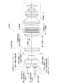
次に、本発明のプロジェクタの実施の形態の構成と機能について図面を参照して説明する。図1は本発明の第1の実施の形態の光学系を備えたプロジェクタの模式的構成図であり、図2は本発明の第1の実施の形態の光学系の模式的構成図である。 Next, the configuration and function of an embodiment of the projector of the present invention will be described with reference to the drawings. FIG. 1 is a schematic configuration diagram of a projector including the optical system according to the first embodiment of the present invention, and FIG. 2 is a schematic configuration diagram of the optical system according to the first embodiment of the present invention.
本発明のプロジェクタ1は、照明光学系10と、液晶パネル53を含む画像形成素子と、投射レンズ55とを有する光学系2を備える。
The
照明光学系10は、第1の色光を発光する第1の光源11と、第2の色光と第3の色光とを選択して発光する第2の光源12と、第1のロッドインテグレータ21と、第2のロッドインテグレータ22と、複数の補助レンズ31〜34と、2個の照明レンズ41、42とを有している。さらに、第1のロッドインテグレータ21と、第2のロッドインテグレータ22との出射面あるいは入射面には本願発明の特徴である選択反射透光膜23、24を備えている。ここでは出射面に設けられているものとして説明する。 The illumination optical system 10 includes a first light source 11 that emits first color light, a second light source 12 that selectively emits second color light and third color light, and a first rod integrator 21. The second rod integrator 22 includes a plurality of auxiliary lenses 31 to 34 and two illumination lenses 41 and 42. Further, selective reflection light-transmitting films 23 and 24 that are the characteristics of the present invention are provided on the exit surface or the incident surface of the first rod integrator 21 and the second rod integrator 22. Here, the description will be made assuming that the light exit surface is provided.
第1の導光部材の光軸71上において、第1の光源11が第1のロッドインテグレータ21の入射面側となるように配置され、第2の導光部材の光軸72上において、第2の光源12が第2のロッドインテグレータ22の入射面側となるように配置されている。 On the optical axis 71 of the first light guide member, the first light source 11 is arranged to be on the incident surface side of the first rod integrator 21, and on the optical axis 72 of the second light guide member, The two light sources 12 are arranged on the incident surface side of the second rod integrator 22.
第1の導光部材の光軸71と第2の導光部材の光軸72とは、照明レンズ光軸73を対称軸として対称に設けられており、第1の光源11と第1のロッドインテグレータ21、および第2の光源12と第2のロッドインテグレータ22もそれぞれ対称の位置に配置されている。 The optical axis 71 of the first light guide member and the optical axis 72 of the second light guide member are provided symmetrically with the illumination lens optical axis 73 as the axis of symmetry, and the first light source 11 and the first rod. The integrator 21, the second light source 12, and the second rod integrator 22 are also arranged at symmetrical positions.
ここでは、照明光学系10の小型化のために、光源11、12には発光ダイオードを使用するものとして説明する。しかし、光源は発光ダイオードに限定されるものではなく、画像形成に使用できる光源であれば例えば有機ELなどの固体光源あっても、本願の照明光学系を適用することができる。 Here, in order to reduce the size of the illumination optical system 10, the light sources 11 and 12 will be described as using light emitting diodes. However, the light source is not limited to a light emitting diode, and the illumination optical system of the present application can be applied to a light source that can be used for image formation, for example, a solid light source such as an organic EL.
発光ダイオードは、単一の色光を発する光源であって、赤、青、緑の発光ダイオードを用いれば、プロジェクタとして広い色再現を実現できる利点がある。 The light emitting diode is a light source that emits a single color light, and if red, blue, and green light emitting diodes are used, there is an advantage that a wide color reproduction can be realized as a projector.
ここでは、第1の光源11には緑色の色光の発光ダイオードが使用されている。実施例では、発光素子の大きさとしては1mm四方の発光素子を4個用い、これらが微小の間隔で同一平面上に並べられており、全体として約2mm四方の大きさの発光面積を有する固体光源が形成されている。 Here, a light emitting diode of green color light is used for the first light source 11. In the embodiment, four 1 mm square light emitting elements are used as the size of the light emitting elements, and these are arranged on the same plane at a minute interval, and as a whole, have a light emitting area of about 2 mm square. A light source is formed.
第2の光源12には青色と赤色の色光の発光ダイオードが使用されている。実施例では、約1mm四方の赤色の発光素子を2個備え、同じく青色の発光素子を2個備え、計4個の発光素子が微小の間隔で同一平面上に並べられており、全体として約2mm四方の発光面積を有する固体光源が形成されている。赤色の発光素子と青色の発光素子とは独立して駆動できる。 For the second light source 12, light emitting diodes of blue and red color lights are used. In the embodiment, two red light-emitting elements each having a size of about 1 mm square, two blue light-emitting elements are provided, and a total of four light-emitting elements are arranged on the same plane at minute intervals. A solid light source having a light emitting area of 2 mm square is formed. The red light emitting element and the blue light emitting element can be driven independently.
光源となる発光ダイオードの発光部の大きさは、実施例のように約2mm四方に限定されるものではない。発光素子の大きさが大きくなれば、それだけ発光光量も増えるが、点灯に必要な消費電力の増大も伴うので、製品の目標性能等の製品企画を勘案して決定される必要がある。 The size of the light emitting portion of the light emitting diode as a light source is not limited to about 2 mm square as in the embodiment. As the size of the light emitting element increases, the amount of emitted light increases accordingly, but it also increases the power consumption necessary for lighting, and therefore needs to be determined in consideration of product planning such as the target performance of the product.
第1の光源の色光と第2の光源の色光も、それぞれ緑色、および青色と赤色に限定されるものではないが、2個のロッドインテグレータ21、22には互いに異なる色光の光源が配置されることが望ましい。 The color light of the first light source and the color light of the second light source are not limited to green, and blue and red, respectively, but the two rod integrators 21 and 22 are provided with light sources of different color lights. It is desirable.
ロッドインテグレータ21および22は、光学ガラス製でも樹脂製でもかまわない。実施例では、大きさとして、上述の光源11、12のサイズに対応させて縦×横が2mm×2.7mmで長さが15mmのものが使用された。 The rod integrators 21 and 22 may be made of optical glass or resin. In the embodiment, the size of the light source 11 or 12 was used with a size of 2 mm × 2.7 mm in length × width and 15 mm in length corresponding to the size of the light sources 11 and 12 described above.
本実施の形態では導光部材をロッドインテグレータとして説明するが、これに限定されるものではなく例えばライトトンネルであってもよい。さらに入射端面と出射端面とが異なる大きさでもよい。ただし、入射端面の大きさは発光素子よりも大きいことが好ましい。 In the present embodiment, the light guide member is described as a rod integrator, but the present invention is not limited to this, and for example, a light tunnel may be used. Further, the entrance end face and the exit end face may have different sizes. However, the size of the incident end face is preferably larger than that of the light emitting element.
また、出射端面の形状としては、表示パネル53のアスペクト比と相似としておくことが好ましい。さらに、ロッドインテグレータの長さは、長いほうが光源の輝度むら低減効果は高いが、その長さも15mmに限定されるものではない。 Further, the shape of the emission end face is preferably similar to the aspect ratio of the display panel 53. Furthermore, the longer the length of the rod integrator, the higher the luminance unevenness reduction effect of the light source, but the length is not limited to 15 mm.
光源とロッドインテグレータとの間隔はできるだけ近い方が好ましい。それは、光源の発光ダイオードから発する光はあらゆる方向に出射しているので、ロッドインテグレータと光源との距離が離れるに従ってロッドインテグレータに入射する光が減ってしまい、その結果、最終的にスクリーンに到達する光量の低下を招くからである。 The distance between the light source and the rod integrator is preferably as close as possible. Because light emitted from the light emitting diode of the light source is emitted in all directions, the light incident on the rod integrator decreases as the distance between the rod integrator and the light source increases, and eventually reaches the screen. This is because the amount of light is reduced.
各々のロッドインテグレータ21、22の入射端面もしくは出射端面には、自らの光源の色光を透過し、他の色光を反射する特性を有する選択反射透光膜23、24が蒸着されている。 Selective reflection light-transmitting films 23 and 24 having characteristics of transmitting color light of their own light source and reflecting other color light are deposited on the incident end face or exit end face of each rod integrator 21 and 22.
図3は選択反射透光膜の反射特性を示すグラフであり、(a)は赤と青とを反射する第1の選択反射透光膜の特性であり、(b)は緑を反射する第2の選択反射透光膜の特性であり、図4はロッドインテグレータと、選択反射透光膜を形成したガラス基板とを示す斜視図である。 FIG. 3 is a graph showing the reflection characteristics of the selective reflection light-transmitting film. (A) shows the characteristics of the first selective reflection light-transmitting film that reflects red and blue, and (b) shows the first characteristic that reflects green. FIG. 4 is a perspective view showing a rod integrator and a glass substrate on which the selective reflection light-transmitting film is formed.
ここでは、第1のロッドインテグレータ21に緑色の第1の光源11が配置され、第2のロッドインテグレータ22には赤色と青色の第2の光源12が配置されている。 Here, the green first light source 11 is arranged on the first rod integrator 21, and the red and blue second light sources 12 are arranged on the second rod integrator 22.
従って、第1のロッドインテグレータ21の入射端面もしくは出射端面には、図3(a)に示した特性のごとく、第2の光源12の青色と赤色の色光を反射し、第1の光源11の緑色の色光は透過させる特性の第1の選択反射透光膜23が蒸着されている。また、第2のロッドインテグレータ22の入射端面もしくは出射端面には、図3(b)に示す特性のような、第1の光源11の緑色の色光を反射し、第2の光源12の青色と赤色の色光を透過させる特性の第2の選択反射透光膜24が蒸着されている。 Therefore, the incident end face or the exit end face of the first rod integrator 21 reflects the blue and red color lights of the second light source 12 as shown in FIG. A first selective reflection transparent film 23 having a characteristic of transmitting green color light is deposited. Further, the incident end face or the exit end face of the second rod integrator 22 reflects the green color light of the first light source 11 as shown in FIG. A second selective reflection light-transmitting film 24 having a characteristic of transmitting red color light is deposited.
このような特性を有する薄膜は、誘電多層膜を真空蒸着すれば得ることができ周知の技術で形成できる。なお、選択反射透光膜は必ずしもロッドインテグレータの入射または出射端面への薄膜形成には限定されない。例えば、図4に示すようにガラス基板82等に選択反射透光膜83を形成して、これをロッドインテグレータ81の入射または出射端面に隣接して配置してもよい。 A thin film having such characteristics can be obtained by vacuum deposition of a dielectric multilayer film and can be formed by a known technique. The selective reflection light-transmitting film is not necessarily limited to the formation of a thin film on the incident or exit end face of the rod integrator. For example, as shown in FIG. 4, a selective reflection light-transmitting film 83 may be formed on a glass substrate 82 or the like and disposed adjacent to the incident or exit end face of the rod integrator 81.
選択反射透光膜23、24は、ここではロッドインテグレータ21、22の出射端面に形成することとしているが、入射端面に形成されていてもよい。 Here, the selective reflection light-transmitting films 23 and 24 are formed on the exit end faces of the rod integrators 21 and 22, but may be formed on the entrance end face.
第1のロットインテグレータ21の出射端面側には第1の補助レンズ31および第2の補助レンズ32が設けられており、第2のロットインテグレータ22の出射端面側には第3の補助レンズ33および第4の補助レンズ34が設けられている。 A first auxiliary lens 31 and a second auxiliary lens 32 are provided on the emission end face side of the first lot integrator 21, and a third auxiliary lens 33 and a second auxiliary lens 32 are provided on the emission end face side of the second lot integrator 22. A fourth auxiliary lens 34 is provided.
これらの補助レンズ31、32の中心軸は、第1のロッドインテグレータ21の中心軸と一致し、補助レンズ33、34の中心軸は、第2のロッドインテグレータ22の中心軸と一致していることが好ましい。ロッドインテグレータの中心軸とは、入射端面の中心と出射端面の中心とを結ぶ直線を意味する。 The central axes of these auxiliary lenses 31 and 32 coincide with the central axis of the first rod integrator 21, and the central axes of the auxiliary lenses 33 and 34 coincide with the central axis of the second rod integrator 22. Is preferred. The central axis of the rod integrator means a straight line connecting the center of the incident end face and the center of the exit end face.
補助レンズには正の屈折力を有するレンズが使用されている。これらの補助レンズは必ずしも必要なわけではないが、光学系を小型化するにはあった方が好ましい。ロッドインテグレータからの出射光束はかなりの広がりもった光束なので、補助レンズによりその広がりを抑制することで、照明レンズの大型化を抑止できるためである。 A lens having a positive refractive power is used as the auxiliary lens. These auxiliary lenses are not necessarily required, but it is preferable to reduce the size of the optical system. This is because the light beam emitted from the rod integrator is a light beam that has spread considerably, and the size of the illumination lens can be suppressed by suppressing the spread by the auxiliary lens.
補助レンズは2枚構成には限定されない。また、補助レンズの外形形状は、円形に限定されるものではない。なぜなら、矩形の出射面を有するロッドインテグレータから出射する光は、その直後においては円形ではないからである。レンズの小型化や製造コストを勘案して決定すればよい。例えば、矩形の補助レンズを使用して、それらを一体成形で得ることも可能である。 The auxiliary lens is not limited to a two-lens configuration. Further, the outer shape of the auxiliary lens is not limited to a circle. This is because light emitted from a rod integrator having a rectangular emission surface is not circular immediately after that. It may be determined in consideration of the miniaturization of the lens and the manufacturing cost. For example, it is possible to obtain them by integral molding using rectangular auxiliary lenses.
ここでは、第1のロッドインテグレータ21と第2のロッドインテグレータ22、第1の補助レンズ31と第3の補助レンズ33、および第2の補助レンズ32と第4の補助レンズ34は光学的に同一諸元のものが使用されている。 Here, the first rod integrator 21 and the second rod integrator 22, the first auxiliary lens 31 and the third auxiliary lens 33, and the second auxiliary lens 32 and the fourth auxiliary lens 34 are optically identical. Specifications are used.
同一諸元とは、焦点距離や屈折率、物理形状が同じであるという意味である。同一諸元のものを使用することで部品の共通化が図れ、大量生産したときのコストメリットを引き出すことができる。 The same specification means that the focal length, the refractive index, and the physical shape are the same. By using parts with the same specifications, parts can be shared, and the cost merit of mass production can be derived.
第2の補助レンズ32、第4の補助レンズ34と液晶パネル53との間には、第1の照明レンズ41および第2の照明レンズ42が配置されている。 Between the second auxiliary lens 32, the fourth auxiliary lens 34, and the liquid crystal panel 53, a first illumination lens 41 and a second illumination lens 42 are arranged.
第1のロッドインテグレータ21に入射する緑色の色光の光(非偏光光)は、たとえ光源に輝度ムラが存在しても、第1のロッドインテグレータ21内での内面反射によって輝度が均一化されて出射端面より出射される。 The light of green color light (unpolarized light) incident on the first rod integrator 21 is made uniform by the internal reflection in the first rod integrator 21 even if the light source has uneven luminance. The light is emitted from the emission end face.
第1のロッドインテグレータ21から出射された光は、第1の補助レンズ31、第2の補助レンズ32によりその広がりが抑制されて、第1の照明レンズ41に入射し、第1の照明レンズ41および第2の照明レンズ42によって、液晶パネル53の表示領域相応の大きさに拡大されて液晶パネル53近傍に結像する。 The light emitted from the first rod integrator 21 is prevented from spreading by the first auxiliary lens 31 and the second auxiliary lens 32, enters the first illumination lens 41, and the first illumination lens 41. The second illumination lens 42 enlarges the image to a size corresponding to the display area of the liquid crystal panel 53 and forms an image near the liquid crystal panel 53.
また、第2の光源12から出射された光も、第3の補助レンズ33、第4の補助レンズ34によりその広がりが抑制されて、第1の照明レンズ41に入射し、第1の照明レンズ41および第2の照明レンズ42によって、液晶パネル53の表示領域相応の大きさに拡大されて液晶パネル53近傍に結像する。 In addition, the light emitted from the second light source 12 is also prevented from spreading by the third auxiliary lens 33 and the fourth auxiliary lens 34, enters the first illumination lens 41, and the first illumination lens 41 and the second illumination lens 42 are enlarged to a size corresponding to the display area of the liquid crystal panel 53 and imaged in the vicinity of the liquid crystal panel 53.
それは、ロッドインテグレータの出射面と液晶パネル面とが共役となるように照明レンズの諸元(焦点距離や形状材質等)が定められているからである。照明レンズと表示パネルの中心軸とは略一致していることが望ましいが一致していなくともかまわない。 This is because the specifications (focal length, shape material, etc.) of the illumination lens are determined so that the exit surface of the rod integrator and the liquid crystal panel surface are conjugate. Although it is desirable that the illumination lens and the central axis of the display panel substantially coincide with each other, they do not have to coincide with each other.
第1の照明レンズ41、第2の照明レンズ42は、第1のロッドインテグレータ21、および第2のロッドインテグレータ22の出射面の照明情報を液晶パネル53の入射面上に結像するように、その配置位置や焦点距離が決定されている。ここでは2枚構成としているが、必ずしも2枚構成に限定する必要はない。 The first illumination lens 41 and the second illumination lens 42 image the illumination information of the exit surfaces of the first rod integrator 21 and the second rod integrator 22 on the entrance surface of the liquid crystal panel 53. The arrangement position and focal length are determined. Although the two-sheet configuration is used here, it is not necessarily limited to the two-sheet configuration.
第2のロッドインテグレータ22に入射する青色と赤色の色光の光(非偏光光)も同様の経路を経て液晶パネル53近傍に結像する。 Blue and red light (non-polarized light) incident on the second rod integrator 22 also forms an image in the vicinity of the liquid crystal panel 53 through a similar path.
画像形成素子は、液晶パネル53と、反射型偏光板51と、1/4波長板52と、偏光板54とを備える。 The image forming element includes a liquid crystal panel 53, a reflective polarizing plate 51, a quarter wavelength plate 52, and a polarizing plate 54.
液晶パネル53の直前には反射型偏光板51が配置されている。この反射型偏光板51は偏光子である。反射型偏光板51は、第2の照明レンズ42から入射した非偏光光に対して、相直交する成分の直線偏光光のうち一方の直線偏光成分を透過させ、他方を反射させる特性を有するものが使用されている。 A reflective polarizing plate 51 is disposed immediately before the liquid crystal panel 53. The reflective polarizing plate 51 is a polarizer. The reflective polarizing plate 51 has a characteristic of transmitting one linearly polarized light component of the linearly polarized light components orthogonal to the non-polarized light incident from the second illumination lens 42 and reflecting the other. Is used.
このような反射型偏光板51は、周知の技術で製造可能であり、商用ルートで入手することができる。図5は反射型偏光板の模式的側面図である。反射型偏光板51には1/4波長板52が反射型偏光板51の入射側に貼合されて一体化された構成となっている。 Such a reflective polarizing plate 51 can be manufactured by a well-known technique and can be obtained by a commercial route. FIG. 5 is a schematic side view of a reflective polarizing plate. The reflective polarizing plate 51 has a structure in which a quarter-wave plate 52 is bonded and integrated on the incident side of the reflective polarizing plate 51.
入射する非偏光光91は透過光92(P偏光、ここでは第1の偏光と略称する)と反射光93(ここでは第2の偏光と略称する)に分離される。第2の偏光は反射型偏光板51で反射された時にはS偏光であるが、1/4波長板52を通過したので円偏光となっている。液晶パネル53の出射側には検光子として偏光板54を備えている。 The incident non-polarized light 91 is separated into transmitted light 92 (P-polarized light, abbreviated as first polarization here) and reflected light 93 (abbreviated as second polarization here). The second polarized light is S-polarized light when reflected by the reflective polarizing plate 51, but is circularly polarized light because it has passed through the quarter-wave plate 52. On the emission side of the liquid crystal panel 53, a polarizing plate 54 is provided as an analyzer.
実施例では、液晶パネル53としては透過型の対角寸法で0.5型の大きさのものが使われた。液晶パネル53は単板型のプロジェクタで構成されているので、液晶の応答速度ができるだけ速いものが好ましい。 In the embodiment, as the liquid crystal panel 53, a transmissive diagonal size having a size of 0.5 type was used. Since the liquid crystal panel 53 is composed of a single-plate projector, it is preferable that the liquid crystal response speed be as fast as possible.
表示パネルとしてLCoSやDMD等を使用することもできるが、この場合には光路を反射光路にするための光学素子が追加になる。装置全体の小型化のためには単一の透過型の液晶を使うことが好ましい。 LCoS, DMD, or the like can be used as the display panel, but in this case, an optical element for making the optical path a reflection optical path is added. In order to reduce the size of the entire apparatus, it is preferable to use a single transmission type liquid crystal.
第1のロッドインテグレータ21から出射されて液晶パネル53に向かう光(非偏光光)のうち、一方の第1の偏光である直線偏光光(たとえばP偏光光)は、液晶パネル53の直前に配置されている反射型偏光板51を透過し、液晶パネル53の照明光として投射レンズ55を通過後に最終的に不図示の投射面上に到達する。ここで反射型偏光板51は、照明レンズの光軸73と垂直であることが望ましい。 Of the light (unpolarized light) emitted from the first rod integrator 21 and directed to the liquid crystal panel 53, one of the first polarized light, linearly polarized light (for example, P-polarized light) is disposed immediately before the liquid crystal panel 53. Then, the light passes through the reflective polarizing plate 51 and passes through the projection lens 55 as illumination light of the liquid crystal panel 53 and finally reaches a projection surface (not shown). Here, the reflective polarizing plate 51 is preferably perpendicular to the optical axis 73 of the illumination lens.
反射型偏光板51で反射された第2の偏光である直線偏光光(例えばS偏光)の殆どは、1/4波長板52を通過して円偏光となり、第2の照明レンズ42から第1の照明レンズ41を経由して、進んできた経路とは逆方向に戻っていく。 Most of the linearly polarized light (for example, S-polarized light) that is the second polarized light reflected by the reflective polarizing plate 51 passes through the quarter-wave plate 52 and becomes circularly polarized light. Through the illumination lens 41 and return in the opposite direction to the route that has been taken.
しかし、第1のロッドインテグレータ21から出射された光線は第1のロッドインテグレータ21の出射面には到達せず、第4の補助レンズ34、第3の補助レンズ33を経由して、照明レンズの光軸73を対称軸として対称の関係にある第2のロッドインテグレータ22の出射面に集光されて到達する。 However, the light beam emitted from the first rod integrator 21 does not reach the emission surface of the first rod integrator 21, and passes through the fourth auxiliary lens 34 and the third auxiliary lens 33 and passes through the illumination lens. The light is condensed and reaches the exit surface of the second rod integrator 22 having a symmetrical relationship with the optical axis 73 as the symmetry axis.
ここで、この第2のロッドインテグレータ22の出射端面に緑色の色光を反射させる特性の第2の選択反射透光膜24が蒸着されているので、入射した光の殆どが第2の選択反射透光膜24で反射されて、再び補助レンズ33、34、および照明レンズ41、42を通過して液晶パネル53に向かって進み、反射型偏光板51まで到達する。 Here, since the second selective reflection transparent film 24 having the characteristic of reflecting the green color light is deposited on the emission end face of the second rod integrator 22, most of the incident light is second selective reflection transparent. The light is reflected by the optical film 24, passes again through the auxiliary lenses 33 and 34, and the illumination lenses 41 and 42 toward the liquid crystal panel 53, and reaches the reflective polarizing plate 51.
第2の選択反射透光膜24と反射型偏光板51との光路の間に位相差版、例えば1/4波長板52が配置されているので、この円偏光光は反射型偏光板51を透過可能な第1の偏光光、すなわちP偏光光に殆どが偏光変換される。 Since a retardation plate, for example, a quarter-wave plate 52 is disposed between the optical path between the second selective reflection light-transmitting film 24 and the reflective polarizing plate 51, the circularly polarized light passes through the reflective polarizing plate 51. Most of the light is converted into polarized light that can be transmitted, that is, P-polarized light.
しかも、第2のロッドインテグレータ22からの照明光と共通の照明レンズ41、42を経由しているので、最初に反射型偏光板51を透過した光も反射された光も同じ結像倍率で液晶パネル53を照明することになる。 In addition, since it passes through the illumination lenses 41 and 42 common to the illumination light from the second rod integrator 22, both the light initially transmitted through the reflective polarizing plate 51 and the reflected light are liquid crystal with the same imaging magnification. The panel 53 will be illuminated.
すなわち、第1の光源11から出射された非偏光の光は、最終的にその殆どがP偏光光に偏光変換されて、液晶パネル53の照明光となる。 That is, most of the non-polarized light emitted from the first light source 11 is finally converted into P-polarized light and becomes illumination light for the liquid crystal panel 53.
一方、例えば赤色と青色の発光ダイオードが1パッケージ化された第2の光源12から第2のロッドインテグレータ22に入射した赤色または青色の光(非偏光光)は、第2のロッドインテグレータ22内での内面反射によりその輝度が均一化されて出射端面より出射される。出射後の光の挙動、進行経路は第1のロッドインテグレータ21の場合と殆ど同様であるので詳細な説明は省略する。 On the other hand, for example, red or blue light (unpolarized light) incident on the second rod integrator 22 from the second light source 12 in which red and blue light emitting diodes are packaged in one package is generated in the second rod integrator 22. The brightness is made uniform by the internal reflection of the light and emitted from the emission end face. Since the behavior and traveling path of the light after emission are almost the same as those in the case of the first rod integrator 21, detailed description thereof is omitted.
異なるのは、第1のロッドインテグレータ21の出射端面に緑色は透光し赤色および青色の色光を反射する特性の第1の選択反射透光膜23が蒸着されている点である。 The difference is that a first selective reflection transparent film 23 having a characteristic of transmitting green light and reflecting red and blue color lights is deposited on the emission end face of the first rod integrator 21.
このように光源から発する非偏光の光のうち、反射型偏光板から反射した成分の光の殆どが偏光板透過可能な直線偏光光に変換されて照明光として利用できるので、高い偏光変換効率と光利用効率とを両立させて液晶パネルの照明を行うことができる。 In this way, most of the component light reflected from the reflective polarizing plate out of the non-polarized light emitted from the light source is converted into linearly polarized light that can be transmitted through the polarizing plate and can be used as illumination light. It is possible to illuminate the liquid crystal panel while achieving both light utilization efficiency.
さらに、異なる色光の光路を合成するための光学素子が不要となるので照明光学系の小型、低コスト化が促進できる。従って、光利用効率の高い、小型で明るいプロジェクタが実現できる。 Furthermore, since an optical element for synthesizing optical paths of different color lights is not required, the illumination optical system can be reduced in size and cost. Therefore, a small and bright projector with high light utilization efficiency can be realized.
各光源の発光ダイオードを順次点灯すれば、すなわち、第1のロッドインテグレータ21に配置されている緑色の発光ダイオードをまず点灯し、それを消灯後、第2のロッドインテグレータ22に配置されている赤色の発光ダイオードを点灯し、それを消灯後に同じ第2のロッドインテグレータ22に配置されている青色の発光ダイオードを点灯する、というような繰り返しの点灯動作を実施することで、時分割で液晶パネル53に緑色、赤色、青色の照明光を順次供給することができるので、その色光の変化に同期させて液晶パネル53を駆動することによってカラー表示が容易に実施できる。 If the light-emitting diodes of the respective light sources are sequentially turned on, that is, the green light-emitting diodes arranged in the first rod integrator 21 are first turned on, then turned off, and then the red arranged in the second rod integrator 22 The light emitting diode is turned on, and the blue light emitting diode arranged in the same second rod integrator 22 is turned on after the light emitting diode is turned off. Since green, red, and blue illumination lights can be sequentially supplied, color display can be easily performed by driving the liquid crystal panel 53 in synchronism with changes in the color lights.
投射レンズ55は、液晶パネル22に形成された画像を投射面に投射するための複数のレンズから構成される。本実施の形態では、単一の液晶表示パネルを用いているので投射レンズのバックフォーカスは短くでき、プロジェクタの光学系全体の小型化も実現しやすい。 The projection lens 55 is composed of a plurality of lenses for projecting an image formed on the liquid crystal panel 22 onto the projection surface. In this embodiment, since a single liquid crystal display panel is used, the back focus of the projection lens can be shortened, and the entire optical system of the projector can be easily downsized.
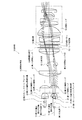
次に本実施の形態のプロジェクタの光学系の動作について図面を参照しながら説明する。図6は本発明の第1の実施の形態のプロジェクタの光学系の動作を説明するための模式的構成図であり、図7は本発明の第1の実施の形態のプロジェクタの光学系の反射型偏光板で反射された光束の動作を説明するための模式的構成図である。図7では反射型偏光板以降の光束の表示を省略している。 Next, the operation of the optical system of the projector according to the present embodiment will be described with reference to the drawings. FIG. 6 is a schematic configuration diagram for explaining the operation of the optical system of the projector according to the first embodiment of the present invention, and FIG. 7 is the reflection of the optical system of the projector according to the first embodiment of the present invention. It is a typical block diagram for demonstrating operation | movement of the light beam reflected by the type | mold polarizing plate. In FIG. 7, the display of the light flux after the reflective polarizing plate is omitted.
図6を参照すると、緑色の色光を発する第1の光源11からの非偏光の光は、まず第1のロッドインテグレータ21の入射端面に入射する。光源は発光ダイオードなので、それから発する光は非偏光の光である。 Referring to FIG. 6, unpolarized light from the first light source 11 that emits green color light first enters the incident end face of the first rod integrator 21. Since the light source is a light emitting diode, the light emitted from it is unpolarized light.
第1のロッドインテグレータ21に入射した非偏光の光は、第1のロッドインテグレータ21の壁面での多数の全反射により、光源の輝度ムラが均一に変換されて出射端面に到達する。 The non-polarized light that has entered the first rod integrator 21 reaches the emission end face after the luminance unevenness of the light source is uniformly converted by numerous total reflections on the wall surface of the first rod integrator 21.
出射端面には、緑色の色光を透過し、青色および赤色の色光を反射させる特性の第1の選択反射透光膜23が形成されているので、出射端面に達した緑色の色光はその殆どが損失なく出射端面より出射される。 Since the first selective reflection light-transmitting film 23 having characteristics of transmitting green color light and reflecting blue and red color light is formed on the emission end face, most of the green color light reaching the emission end face is formed. The light is emitted from the emission end face without loss.
出射端面の直後には、正の屈折力を有する第1の補助レンズ31および第2の補助レンズ32の2枚が配置されており、第1のロットインテグレータ21から出射された光は、その補助レンズ31、32により拡散が抑制されて第1の照明レンズ41に入射する。 The first auxiliary lens 31 and the second auxiliary lens 32 having a positive refractive power are disposed immediately after the emission end face, and the light emitted from the first lot integrator 21 is supplemented by the auxiliary lens 31. Diffusion is suppressed by the lenses 31 and 32 and enters the first illumination lens 41.
その後、第1の照明レンズ41および第2の照明レンズ42を経由して、液晶パネル53の画像表示領域を照明する。 Thereafter, the image display area of the liquid crystal panel 53 is illuminated via the first illumination lens 41 and the second illumination lens 42.
ロッドインテグレータ21の出射端面は矩形であり、かつ液晶パネル53の画像表示領域と相似形であるので、出射端面と液晶表示パネルの画像表示領域とがほぼ共役関係となるように照明レンズ41および42の諸元(相互の位置関係とレンズの焦点距離など)が定められている。 Since the exit end face of the rod integrator 21 is rectangular and has a similar shape to the image display area of the liquid crystal panel 53, the illumination lenses 41 and 42 are arranged so that the exit end face and the image display area of the liquid crystal display panel are substantially conjugated. (The mutual positional relationship and the focal length of the lens, etc.) are determined.
図6の入射光束61はロッドインテグレータ21の出射端面と液晶パネル53との共役関係を示すものである。 An incident light beam 61 in FIG. 6 indicates a conjugate relationship between the exit end face of the rod integrator 21 and the liquid crystal panel 53.
液晶表示パネル53の直前には反射型偏光板51があり、液晶パネル53に達する非偏光の直交する直線偏光成分の光のうち、例えば第1の偏光であるP偏光の光が反射型偏光板51を透過して液晶パネル53に到達する。この光が液晶パネルの照明光となる。 A reflective polarizing plate 51 is provided immediately before the liquid crystal display panel 53, and P-polarized light, which is the first polarized light, for example, out of non-polarized, linearly polarized light components reaching the liquid crystal panel 53 is reflected. 51 is transmitted and reaches the liquid crystal panel 53. This light becomes illumination light for the liquid crystal panel.
なお、反射型偏光板51の光源側には1/4波長板52が貼合されているが、非偏光の光は1/4波長板52を透過しても非偏光のままである。もう一方の偏光成分の光、例えば第2の偏光であるS偏光光はその殆どが反射される。反射型偏光板51と液晶パネル53との間隔はできるだけ接近していることが好ましい。 In addition, although the quarter wavelength plate 52 is bonded to the light source side of the reflective polarizing plate 51, the non-polarized light remains unpolarized even if it passes through the quarter wavelength plate 52. Most of the other polarized light component, for example, S-polarized light as the second polarized light is reflected. The distance between the reflective polarizing plate 51 and the liquid crystal panel 53 is preferably as close as possible.
液晶パネル53の照明に寄与した光は、液晶パネル53を透過後、検光子である偏光板54、投射レンズ55を経由して不図示の投射面に液晶パネル53の画像を拡大投射する。 The light that has contributed to the illumination of the liquid crystal panel 53 passes through the liquid crystal panel 53 and then enlarges and projects the image of the liquid crystal panel 53 on a projection surface (not shown) via the polarizing plate 54 and the projection lens 55 that are analyzers.
反射型偏光板51で反射された第2の偏光であるS偏光の光の動作を、図7を用いて説明する。第1のロッドインテグレータ21から出射されて反射型偏光板51に達する非偏光の入射光束61のうち、反射されたS偏光の光は、反射型偏光板51の光源側に貼合されている1/4波長板52により直ちに円偏光に偏光変換されて、第2の照明レンズ42および第1の照明レンズ41を逆方向に進行して行く。即ち第1の反射光束63および第2の反射光束64である。
The operation of S-polarized light that is the second polarized light reflected by the reflective polarizing plate 51 will be described with reference to FIG. Of the unpolarized incident light beam 61 that is emitted from the first rod integrator 21 and reaches the reflective polarizing plate 51, the reflected S-polarized light is bonded to the light source side of the reflective
これらの光は、今度は第2の照明レンズ42、第1の照明レンズ41、第4の補助レンズ34、および第3の補助レンズ33を経由して、第2のロッドインテグレータ22の出射端面に集光する。 These lights now pass through the second illumination lens 42, the first illumination lens 41, the fourth auxiliary lens 34, and the third auxiliary lens 33 to the emission end face of the second rod integrator 22. Condensate.
それは、図2に示されるように第1の導光部材の光軸71と第2の導光部材の光軸72とが照明レンズの光軸73(中心軸)に対してT=T’となるように照明レンズの光軸73を対称軸として対称の関係に配置されていて、出射端面と液晶表示パネルの画像表示領域とがほぼ共役関係となるように照明レンズ41および42の諸元が設定されているからである。 As shown in FIG. 2, the optical axis 71 of the first light guide member and the optical axis 72 of the second light guide member are T = T ′ with respect to the optical axis 73 (center axis) of the illumination lens. Thus, the specifications of the illumination lenses 41 and 42 are arranged so as to be symmetric with respect to the optical axis 73 of the illumination lens as the symmetry axis, and the emission end face and the image display area of the liquid crystal display panel are substantially in a conjugate relationship. This is because it is set.
第2のロッドインテグレータ22の出射端面には、緑色の色光を反射し、赤色および青色の色光を透過させる特性を有する第2の選択反射透光膜24が形成されている。従って、この第2のロッドインテグレータ22の出射面に集光する緑色の色光(円偏光)は、出射面の第2の選択反射透光膜24でその殆どが反射され、再び液晶パネル53の方向に向かって進行して行く第1の反射光束63および第2の反射光束64に変わる。これは、緑色の色光の二次光源が第2のロッドインテグレータ22の出射端面に出現したのと等価と見ることもできる。 On the emission end face of the second rod integrator 22, a second selective reflection light-transmitting film 24 having the characteristics of reflecting green color light and transmitting red and blue color light is formed. Therefore, most of the green color light (circularly polarized light) condensed on the exit surface of the second rod integrator 22 is reflected by the second selective reflection light-transmitting film 24 on the exit surface, and the direction of the liquid crystal panel 53 again. Into a first reflected light beam 63 and a second reflected light beam 64 that travel toward. This can be regarded as equivalent to the appearance of the secondary light source of green color light on the exit end face of the second rod integrator 22.
この第1の反射光束63および第2の反射光束64は、第3の補助レンズ33、第4の補助レンズ34、第1の照明レンズ41および第2の照明レンズ42により所定の倍率、すなわち、液晶表示パネル53の表示領域相応の大きさに拡大されて、液晶パネル直前の反射型偏光板51に達する。 The first reflected light beam 63 and the second reflected light beam 64 are given a predetermined magnification by the third auxiliary lens 33, the fourth auxiliary lens 34, the first illumination lens 41, and the second illumination lens 42, that is, It is enlarged to a size corresponding to the display area of the liquid crystal display panel 53 and reaches the reflective polarizing plate 51 immediately before the liquid crystal panel.
これも、第1の導光部材の光軸71と第2の導光部材の光軸72とが照明レンズの光軸73(中心軸)に対してT=T’となるように照明レンズの光軸73を対称軸として対称の関係に配置されており、第1のロッドインテグレータ21と第2のロッドインテグレータ22に対応する補助レンズの諸元が同一だからである。 This is also because the optical axis 71 of the first light guide member and the optical axis 72 of the second light guide member are T = T ′ with respect to the optical axis 73 (center axis) of the illumination lens. This is because the optical axes 73 are arranged symmetrically with respect to the symmetry axis, and the specifications of the auxiliary lenses corresponding to the first rod integrator 21 and the second rod integrator 22 are the same.
ここで、先にも説明したように、反射型偏光板51には1/4波長板52が貼合されおり、この1/4波長板52を通過した光束は直ちに円偏光からP偏光光に偏光変換される。即ち、この偏光変換により反射型偏光板51を透過可能な偏光成分の光に変化する。 Here, as described above, the quarter-wave plate 52 is bonded to the reflective polarizing plate 51, and the light beam that has passed through the quarter-wave plate 52 immediately changes from circularly polarized light to P-polarized light. Polarized light is converted. In other words, this polarization conversion changes the light into a polarized light component that can be transmitted through the reflective polarizing plate 51.
そして、この光は液晶パネル53の照明光として、偏光板54と投射レンズ55を経由して不図示の投射面に液晶パネル53の画像を拡大投射する。 This light is used as illumination light for the liquid crystal panel 53 to enlarge and project an image of the liquid crystal panel 53 on a projection surface (not shown) via the polarizing plate 54 and the projection lens 55.
このようにして、緑色の発光ダイオードからの非偏光の光は、反射型偏光板51での偏光分離そして1/4波長板52での偏光変換という過程を通じて、その殆どが液晶パネル53の照明光として利用されるので、非常に高い光利用効率が得られる。しかも偏光分離後の光は一旦集光され、そのほとんどが再度、反射型偏光板51を透過可能な偏光成分に変換されるので非常に高い偏光変換効率を達成できる。 In this way, most of the non-polarized light from the green light-emitting diode is illuminated by the liquid crystal panel 53 through the process of polarization separation at the reflective polarizing plate 51 and polarization conversion at the quarter-wave plate 52. Therefore, very high light utilization efficiency can be obtained. In addition, the light after polarization separation is once condensed, and most of the light is converted again into a polarized light component that can be transmitted through the reflective polarizing plate 51, so that very high polarization conversion efficiency can be achieved.
次に、第2のロッドインテグレータ22の入射端面に配置される第2の光源12の赤色および青色の発光ダイオードからの光について、その動作を説明する。 Next, the operation of the light from the red and blue light emitting diodes of the second light source 12 disposed on the incident end face of the second rod integrator 22 will be described.
その動作は第1のロッドインテグレータ21に配置された第1の光源からの緑色の光の動作と殆ど同様である。異なるのは、反射型偏光板51で反射され、第1のロッドインテグレータ21の出射端面に戻ってきたとき、この出射端面には赤色および青色の色光を反射する特性を有する第1の選択反射透光膜23が形成されていることである。 The operation is almost the same as the operation of green light from the first light source disposed in the first rod integrator 21. The difference is that when the light is reflected by the reflective polarizing plate 51 and returns to the exit end face of the first rod integrator 21, the exit end face has a characteristic of reflecting red and blue color light. That is, the optical film 23 is formed.
即ち、第2のロッドインテグレータ22から出射された赤色または青色の光(非偏光光)は、先ず、第3の補助レンズ33、第4の補助レンズ34、第1の照明レンズ41、および第2の照明レンズ42により所定の倍率で拡大されて液晶パネル53直前の反射型偏光板51に達する。ここで、第1の偏光であるP偏光の光が反射型偏光板51を透過して液晶パネル53に到達し、反射型偏光板51で反射されるS偏光の偏光成分の光は、反射型偏光板51に貼合されている1/4波長板52を透過して円偏光の光となって、逆方向すなわち、光源側に進行してゆく。 That is, red or blue light (unpolarized light) emitted from the second rod integrator 22 is firstly converted into the third auxiliary lens 33, the fourth auxiliary lens 34, the first illumination lens 41, and the second light. The illumination lens 42 is magnified by a predetermined magnification and reaches the reflective polarizing plate 51 immediately before the liquid crystal panel 53. Here, the P-polarized light that is the first polarized light passes through the reflective polarizing plate 51 and reaches the liquid crystal panel 53, and the S-polarized light component reflected by the reflective polarizing plate 51 is reflected by the reflective polarizing plate 51. The light passes through the quarter-wave plate 52 bonded to the polarizing plate 51, becomes circularly polarized light, and travels in the opposite direction, that is, toward the light source.
この光は、第2の照明レンズ42、第1の照明レンズ41、第2の補助レンズ32、および第1の補助レンズ31を進行後、第1のロッドインテグレータ21の出射端面に集光する。 The light travels through the second illumination lens 42, the first illumination lens 41, the second auxiliary lens 32, and the first auxiliary lens 31, and then is collected on the emission end face of the first rod integrator 21.
そして、出射端面に形成された赤色および青色の色光を反射し、緑色の色光を透過させる特性を有する第2の選択反射透光膜24によって、入射した赤色.および青色の色光(円偏光)は、出射面でその殆どが反射され、再び液晶パネル53の方向に進行してゆく反射光束に変わる。これは、赤色または青色の色光の二次光源が第1のロッドインテグレータ21の出射端面に出現したのと等価と見ることもできる。 Then, the incident red and blue color lights (circularly polarized light) are reflected by the second selective reflection light-transmitting film 24 having the characteristics of reflecting the red and blue color lights formed on the emission end face and transmitting the green color lights. Most of the light is reflected on the light exit surface, and the reflected light beam travels in the direction of the liquid crystal panel 53 again. This can be regarded as equivalent to a secondary light source of red or blue color light appearing on the exit end face of the first rod integrator 21.
再び液晶パネル側に進路を変更した赤色または青色の色光は、第1の補助レンズ31、第2の補助レンズ32、第1の照明レンズ41、および第2の照明レンズ42の順番に進行したあと、反射型偏光板51に貼合されている1/4波長板52に到達し、ここで円偏光光からP偏光光への偏光変換が実施されて反射型偏光板51を透過可能な光となって液晶パネル53の照明に寄与できる。緑色の色光のときと同様、高い偏光変換効率と高い光利用効率を得ることが可能である。 After the red or blue color light whose path has been changed to the liquid crystal panel again proceeds in the order of the first auxiliary lens 31, the second auxiliary lens 32, the first illumination lens 41, and the second illumination lens 42. The light reaches the quarter-wave plate 52 bonded to the reflective polarizing plate 51, where the polarization conversion from the circularly polarized light to the P-polarized light is performed, and the light that can be transmitted through the reflective polarizing plate 51. This contributes to the illumination of the liquid crystal panel 53. As in the case of green color light, high polarization conversion efficiency and high light utilization efficiency can be obtained.
図8は、第1のロッドインテグレータおよび第2のロッドインテグレータを出射した光束のうち、反射型偏光板を透過した光と、反射型偏光板で反射され、第2のロッドインテグレータおよび第1のロッドインテグレータまで戻って反射され、再度反射型偏光板に到達後、偏光変換されて液晶パネルに到達した光の両方を描いた光路図である。 FIG. 8 shows the light transmitted through the reflection type polarizing plate among the light beams emitted from the first rod integrator and the second rod integrator, and reflected by the reflection type polarizing plate, and the second rod integrator and the first rod. FIG. 5 is an optical path diagram depicting both light that has been reflected back to the integrator, reflected again, reached the reflective polarizing plate, and then polarized and reached the liquid crystal panel.
なお、第1および第2のロッドインテグレータの出射端面に、それぞれ選択反射透光膜を形成した例で説明したが、選択反射透光膜の形成場所としてはロッドインテグレータの出射端面に限定されるものでなく、入射端面に形成されていても同様の動作および効果を実現できる。すなわち、第1のロッドインテグレータの入射端面に緑の光を透過させ、赤および青の光を反射する特性の選択反射透光膜を形成し、第2のロッドインテグレータの入射端面に赤および青の光を透過させ、緑の光を反射する特性の選択反射透光膜を形成してもよい。 In addition, although the example in which the selective reflection light-transmitting film is formed on each of the emission end faces of the first and second rod integrators has been described, the formation location of the selective reflection light-transmitting film is limited to the emission end face of the rod integrator. In addition, the same operation and effect can be realized even if it is formed on the incident end face. That is, a selective reflection light-transmitting film having a characteristic of transmitting green light to the incident end face of the first rod integrator and reflecting red and blue light is formed, and red and blue are formed on the incident end face of the second rod integrator. A selective reflection light-transmitting film having a characteristic of transmitting light and reflecting green light may be formed.
それは、反射型偏光板から戻ってきて、各ロッドインテグレータの出射端面に集光する光は、そこからロッドインテグレータに進入し、反射されながらロッドインテグレータの入射端面に達するからである。しかもロッドインテグレータ内を進行中は、ロッドインテグレータ壁面での反射が全反射なので光の損失も殆ど起きない。従って、選択反射透光膜がロッドインテグレータの入射端面にあっても出射端面にあっても、同様の効果を得られる。 This is because the light returning from the reflection type polarizing plate and condensed on the exit end face of each rod integrator enters the rod integrator from there and reaches the entrance end face of the rod integrator while being reflected. In addition, while traveling through the rod integrator, the reflection on the wall of the rod integrator is totally reflected, so that almost no light loss occurs. Therefore, the same effect can be obtained regardless of whether the selective reflection light-transmitting film is on the entrance end face or the exit end face of the rod integrator.
次に、本発明のプロジェクタの第2の実施の形態について図面を参照して説明する。図9は、第2の実施の形態のプロジェクタの光学系の模式的斜視図であり、図10は第2の実施の形態のプロジェクタの光学系の模式的上面図であり、図11は第2の実施の形態のプロジェクタの光学系の模式的側面図であり、図12は第2の実施の形態の光源とロッドインテグレータと補助レンズを示す斜視図である。 Next, a second embodiment of the projector of the present invention will be described with reference to the drawings. FIG. 9 is a schematic perspective view of the optical system of the projector according to the second embodiment, FIG. 10 is a schematic top view of the optical system of the projector according to the second embodiment, and FIG. FIG. 12 is a schematic side view of the optical system of the projector according to the embodiment, and FIG. 12 is a perspective view showing a light source, a rod integrator, and an auxiliary lens according to the second embodiment.
プロジェクタの輝度を増加させるために光源を増やすことは容易に可能である。光源を増やせば、それに応じて高輝度化が期待できる。 It is easy to increase the number of light sources to increase the brightness of the projector. If the number of light sources is increased, higher brightness can be expected.
第1の実施の形態では、光源としては、緑の色光の発光ダイオードと赤色と青色の色光の発光ダイオードが1パッケージ化された発光素子をそれぞれ1個使用していた。しかし、例えば図9の斜視図に示すごとく、光源を6個備えた構成をとることもできる。光源を増やせば、それに応じて高輝度化が期待できる。 In the first embodiment, as the light source, one light emitting element in which a light emitting diode of green color light and a light emitting diode of red and blue color light are packaged is used. However, for example, as shown in the perspective view of FIG. 9, a configuration including six light sources may be employed. If the number of light sources is increased, higher brightness can be expected.
図12に示すように、光源付近では、6個の光源のうち、緑色の発光ダイオードを備えた第1の光源111を3個備え、赤色と青色の発光ダイオードが1パッケージ化した発光素子を備えた第2の光源112を3個備えている。 As shown in FIG. 12, in the vicinity of the light source, among the six light sources, three first light sources 111 having green light emitting diodes are provided, and a light emitting element in which red and blue light emitting diodes are packaged is provided. In addition, three second light sources 112 are provided.
ここでは、第1の光源111と第1のロッドインテグレータ121とからなる第1の光源部と、第2の光源112と第2のロッドインテグレータ122からなる第2の光源部との組合せが複数設けられ、それぞれの1組の第1の光源部の第1の導光部材の光軸と、第2の光源部の第2の導光部材の光軸とは、照明レンズ光軸73を対称軸として対象に配置されており、かつ複数の第1の導光部材の光軸、および複数の第2の導光部材の光軸は、それぞれが同一平面上に配置されている、
即ち、図12では、第1の光源111aが第2の光源112cと1組となり、第1の光源111bが第2の光源112bと1組となり、第1の光源111cが第2の光源112aと1組となっている。
Here, a plurality of combinations of a first light source unit made up of the first light source 111 and the first rod integrator 121 and a second light source unit made up of the second light source 112 and the second rod integrator 122 are provided. The optical axis of the first light guide member of each pair of the first light source units and the optical axis of the second light guide member of the second light source unit are symmetrical with respect to the illumination lens optical axis 73. And the optical axes of the plurality of first light guide members and the optical axes of the plurality of second light guide members are respectively disposed on the same plane.
That is, in FIG. 12, the first light source 111a and the second
例えば、第1の光源111aの出射光の反射型偏光板51からの反射光は第2の光源112cの第2のロッドインテグレータ122cの出射端に入射し、第2の光源112cの出射光の反射型偏光板51からの反射光は第1の光源111aの第1のロッドインテグレータ121aの出射端に入射する。
For example, the reflected light from the reflective polarizing plate 51 of the light emitted from the first light source 111a is incident on the light output end of the second rod integrator 122c of the second
図10のYZ面を示す上面図に示されるように、3個ある第2の光源112a、112b、112cは、赤色と青色の発光素子が1パッケージ化した発光ダイオードを備えた光源である。この3個の第2の光源112の発光面は、3個の第2のロッドインテグレータ122a、122b、122cの入射面に近接して設けられている。3個の第2のロッドインテグレータ122のそれぞれの出射面に近接して、第3の補助レンズ133a、133b、133cが設けられている。
As shown in the top view showing the YZ plane in FIG. 10, the three second
3個の第2のロッドインテグレータ122の出射端には、第1の光源111の緑色の色光を反射し、第2の光源112の青色と赤色の色光を透過させる特性の第2の選択反射透光膜124が蒸着されている。 At the emission ends of the three second rod integrators 122, a second selective reflection transmission characteristic of reflecting the green color light of the first light source 111 and transmitting the blue and red color lights of the second light source 112. An optical film 124 is deposited.
図10における第2の光源、第2のロッドインテグレータ、および第3の補助レンズのそれぞれの下側には、一部が図11に示されるように、不図示の第1の光源111a、111b、111c、第1のロッドインテグレータ121a、121b、121c、および第1の補助レンズ131a、131b、131cが設けられている。 On the lower side of each of the second light source, the second rod integrator, and the third auxiliary lens in FIG. 10, as shown in part in FIG. 11, first light sources 111 a, 111 b, not shown, 111c, first rod integrators 121a, 121b, and 121c, and first auxiliary lenses 131a, 131b, and 131c are provided.
3個の第1のロッドインテグレータ121の出射端面には、第2の光源112の青色と赤色の色光を反射し、第1の光源111の緑色の色光を透過させる特性の第1の選択反射透光膜123が蒸着されている。 The first end surface of the three first rod integrators 121 reflects the blue and red color light of the second light source 112 and transmits the green color light of the first light source 111. An optical film 123 is deposited.
3個の第1の補助レンズ131および3個の第3の補助レンズ133のそれぞれの出射側には、第2の補助レンズ132a、132b、132cと第4の補助レンズ134a、134b、134cとが一体となった第2の補助レンズ群135が設けられている。
The second auxiliary lenses 132a, 132b, 132c and the fourth
第2の補助レンズ群135からの出射光は、第1の照明レンズ41に入射する。第1の照明レンズ41以降の構成と動作は第1の実施の形態と同じなので、同じ符号を付して説明を省略する。 The light emitted from the second auxiliary lens group 135 enters the first illumination lens 41. Since the configuration and operation after the first illumination lens 41 are the same as those in the first embodiment, the same reference numerals are given and description thereof is omitted.
光源の数が増えても、第1の照明レンズ41と第2の照明レンズ42の設計仕様を対応させることにより、各光源から発した光の動作は第1の実施の形態と同じとすることができ、高い偏光変換効率が維持され、光源が増加したことに対応して格段の高輝度が達成できる。ここでは、それぞれを3個の光源としているが、3個に限定されるものではない。 Even if the number of light sources increases, the operation of the light emitted from each light source is made the same as in the first embodiment by making the design specifications of the first illumination lens 41 and the second illumination lens 42 correspond. High polarization conversion efficiency is maintained, and extremely high luminance can be achieved in response to the increase in the number of light sources. Here, three light sources are used, but the number of light sources is not limited to three.
次に、本発明のプロジェクタの第3の実施の形態について図面を参照して説明する。図13は第3の実施の形態の光源とロッドインテグレータと補助レンズを示す斜視図である。 Next, a third embodiment of the projector of the present invention will be described with reference to the drawings. FIG. 13 is a perspective view showing a light source, a rod integrator, and an auxiliary lens according to the third embodiment.
第3の実施の形態は、第2の実施の形態の応用例であり、光源の数が増加したことから光源には単色の発光ダイオードを使用した。第1および第2の実施の形態では、青色と赤色の発光ダイオードを1パッケージ化した光源を用いたが、第3の実施の形態では赤色のみの発光ダイオードと青色のみの発光ダイオードをそれぞれ1パッケージ化した光源を用いて光源部を構成した。 The third embodiment is an application example of the second embodiment. Since the number of light sources is increased, a monochromatic light emitting diode is used as the light source. In the first and second embodiments, a light source in which blue and red light emitting diodes are packaged is used. In the third embodiment, only a red light emitting diode and a blue light emitting diode are packaged in one package. A light source unit was configured using the converted light source.
図13に示すような配置で、緑色の発光ダイオードからなる第1の光源211と、赤色の発光ダイオードからなる第3の光源213と、青色の発光ダイオードからなる第4の光源214とを使用することもできる。 In the arrangement shown in FIG. 13, a first light source 211 made of a green light emitting diode, a third light source 213 made of a red light emitting diode, and a fourth light source 214 made of a blue light emitting diode are used. You can also.
図13の例では、緑色の発光ダイオードからなる第1の光源211が3個下段に配置されており、赤色の発光ダイオードからなる第3の光源213の2個と青色の発光ダイオードからなる第4の光源214の1個との計3個が上段に配置されている。どのような組み合わせにするかは、使用する発光ダイオードの光出力に応じて適宜決めればよい。 In the example of FIG. 13, three first light sources 211 made of green light emitting diodes are arranged in the lower stage, two third light sources 213 made of red light emitting diodes, and a fourth light source made of blue light emitting diodes. A total of three light sources 214 and one light source 214 are arranged in the upper stage. What kind of combination should be determined may be appropriately determined according to the light output of the light emitting diode to be used.
この組み合わせの場合には、ロッドインテグレータに設けられる選択反射透光膜は第1の実施の形態と同じでよい。 In the case of this combination, the selective reflection light-transmitting film provided in the rod integrator may be the same as that in the first embodiment.
次に、本発明のプロジェクタの第4の実施の形態について図面を参照して説明する。図14は第4の実施の形態の光学系の模式的構成図であり、図15は、本発明の第4の実施の形態のプロジェクタの光学系の反射型偏光板で反射された光束の動作を説明するための模式的構成図である。 Next, a fourth embodiment of the projector of the invention will be described with reference to the drawings. FIG. 14 is a schematic configuration diagram of the optical system of the fourth embodiment, and FIG. 15 shows the operation of the light beam reflected by the reflective polarizing plate of the projector optical system of the fourth embodiment of the invention. It is a typical block diagram for demonstrating.
第4の実施の形態では、図14に示すように、第1の光源311、第1のロッドインテグレータ321、第1の補助レンズ331、および第2の補助レンズ332の第1の導光部材の光軸371と、第2の光源312、第2のロッドインテグレータ322、第3の補助レンズ333、および第4の補助レンズ334の第2の導光部材の光軸72とが直交するように配置されている。 In the fourth embodiment, as shown in FIG. 14, the first light guide member of the first light source 311, the first rod integrator 321, the first auxiliary lens 331, and the second auxiliary lens 332 is provided. The optical axis 371 and the second light source 312, the second rod integrator 322, the third auxiliary lens 333, and the optical axis 72 of the second light guide member of the fourth auxiliary lens 334 are arranged so as to be orthogonal to each other. Has been.
そのため、第2の導光部材の光軸72を直角に折り曲げるための反射ミラー341を備えている。照明レンズ光軸73と、第1の導光部材の光軸371および第2の導光部材の光軸372aとは、結果的に平行でかつ、照明レンズ光軸73と距離T、およびT’だけ離れている。T=T'であることが好ましい。 Therefore, a reflection mirror 341 for bending the optical axis 72 of the second light guide member at a right angle is provided. The illumination lens optical axis 73, the optical axis 371 of the first light guide member, and the optical axis 372a of the second light guide member are consequently parallel, and the illumination lens optical axis 73 and the distance T, and T ′. Just away. It is preferable that T = T ′.
動作の説明は省略する。なぜなら、このような配置であっても、第1の実施の形態で説明した効果が得られることは自明であるからである。図15には、この構成による、光路図が示されている。光路図にはロッドインテグレータから反射型偏光板までの光線が描かれており、偏光板以降の光線の描画は省略してある。 The description of the operation is omitted. This is because it is obvious that the effects described in the first embodiment can be obtained even with such an arrangement. FIG. 15 shows an optical path diagram according to this configuration. In the optical path diagram, light rays from the rod integrator to the reflective polarizing plate are drawn, and drawing of light rays after the polarizing plate is omitted.
この配置によれば、第1の光源311、第1のロッドインテグレータ321、第1の補助レンズ331、および第2の補助レンズ332と、第2の光源312、第2のロッドインテグレータ322、第3の補助レンズ333、および第4の補助レンズ334とを平行に配置する必要がない。従って、光学系全体を、プロジェクタの外装ケースに収容するときに、光学系以外のプロジェクタ構成要素である電気回路基板等も含めて配置の空間自由度の高い設計が可能となる。すなわち、デザイン性に富んだ外形設計に寄与するものである。 According to this arrangement, the first light source 311, the first rod integrator 321, the first auxiliary lens 331, and the second auxiliary lens 332, the second light source 312, the second rod integrator 322, the third The auxiliary lens 333 and the fourth auxiliary lens 334 need not be arranged in parallel. Therefore, when the entire optical system is housed in the exterior case of the projector, it is possible to design with a high degree of spatial freedom in arrangement including the electric circuit board that is a projector component other than the optical system. That is, it contributes to an external design with a rich design.
次に、本発明のプロジェクタの第5の実施の形態について図面を参照して説明する。図16は第5の実施の形態の光学系の模式的構成図であり、図17は、本発明の第5の実施の形態のプロジェクタの光学系の反射型偏光板で反射された光束の動作を説明するための模式的構成図である。 Next, a fifth embodiment of the projector of the invention will be described with reference to the drawings. FIG. 16 is a schematic configuration diagram of the optical system of the fifth embodiment, and FIG. 17 shows the operation of the light beam reflected by the reflective polarizing plate of the optical system of the projector of the fifth embodiment of the invention. It is a typical block diagram for demonstrating.
図14、図15に示す第4の実施の形態と、図16、図17に示す第5の実施の形態との違いは、第5の実施の形態では第1の導光部材の光軸471と第2の導光部材の光軸472の両方ともが、第1の反射ミラー441および第2の反射ミラー442を用いて、中間で直角に光軸を折り曲げている点である。 The difference between the fourth embodiment shown in FIGS. 14 and 15 and the fifth embodiment shown in FIGS. 16 and 17 is that the optical axis 471 of the first light guide member in the fifth embodiment. And the optical axis 472 of the second light guide member is that the optical axis is bent at a right angle in the middle using the first reflection mirror 441 and the second reflection mirror 442.
当然のこととして、このような構成にしても、高い偏光変換効率と、高い光利用効率は達成される。この配置では特に照明レンズの光軸方向の距離Lを短くすることができるので、光学系をコンパクトにできるという効果がある。第4の実施の形態と同様に、断面光路図の一部を図17に示す。ここでも偏光板以降の光線の描画は省略してある。 Naturally, even with such a configuration, high polarization conversion efficiency and high light utilization efficiency are achieved. In this arrangement, the distance L in the optical axis direction of the illumination lens can be particularly shortened, so that the optical system can be made compact. As in the fourth embodiment, a part of the sectional optical path diagram is shown in FIG. Here, the drawing of light rays after the polarizing plate is omitted.
1 プロジェクタ
2 光学系
10 照明光学系
11、111a、111b、111c、211a、211b、211c、311、411 第1の光源
12、112a、112b、112c、212、312、412 第2の光源
21、121、221a、221b、221c、321、421 第1のロッドインテグレータ
22、122、222a、222b、222c、322、422 第2のロッドインテグレータ
23、123a、123b、123c、223、323、423 第1の選択反射透光膜
24、124a、124b、124c、224、324、424 第2の選択反射透光膜
31、131、231、331、431 第1の補助レンズ
32、132、232、332、432 第2の補助レンズ
33、133a、133b、133c、233、333、433 第3の補助レンズ
34、134、234、334、434 第4の補助レンズ
41 第1の照明レンズ
42 第2の照明レンズ
51 反射型偏光板
52 1/4波長板
53 液晶パネル
54 偏光板
55 投射レンズ
61 入射光束
63 第1の反射光束
64 第2の反射光束
71、371、471a、471b 第1の導光部材の光軸
72、372a、372b、472a、472b 第2の導光部材の光軸
73 照明レンズ光軸
81 ロッドインテグレータ
82 ガラス基板
83 選択反射透光膜
91 非偏光光
92 透過光(P偏光)
93 反射光(円偏光)
135 第2の補助レンズ群
213a、213b 第3の光源
214 第4の光源
341 反射ミラー
441 第1の反射ミラー
442 第2の反射ミラー
DESCRIPTION OF SYMBOLS 1 Projector 2 Optical system 10 Illumination optical system 11, 111a, 111b, 111c, 211a, 211b, 211c, 311, 411 First light source 12, 112a, 112b, 112c, 212, 312, 412 Second light source 21, 121 221a, 221b, 221c, 321, 421 First rod integrator 22, 122, 222a, 222b, 222c, 322, 422 Second rod integrator 23, 123a, 123b, 123c, 223, 323, 423 First selection Reflective translucent film 24, 124a, 124b, 124c, 224, 324, 424 Second selective reflective translucent film 31, 131, 231, 331, 431 First auxiliary lens 32, 132, 232, 332, 432 Second Auxiliary lenses 33, 133a, 133b, 13 3c, 233, 333, 433 Third auxiliary lens 34, 134, 234, 334, 434 Fourth auxiliary lens 41 First illumination lens 42 Second illumination lens 51 Reflective polarizing plate 52 1/4 wavelength plate 53 Liquid crystal panel 54 Polarizing plate 55 Projection lens 61 Incident light beam 63 First reflected light beam 64 Second reflected light beam 71, 371, 471a, 471b Optical axes of first light guide member 72, 372a, 372b, 472a, 472b Second Optical axis of the light guide member 73 Illuminating lens optical axis 81 Rod integrator 82 Glass substrate 83 Selective reflective transparent film 91 Non-polarized light 92 Transmitted light (P-polarized light)
93 Reflected light (circularly polarized light)
135 Second auxiliary lens group 213a, 213b Third light source 214 Fourth light source 341 Reflecting mirror 441 First reflecting mirror 442 Second reflecting mirror
Claims (10)
前記第1の色光は透過し前記第2の色光および前記第3の色光は反射する選択反射透光膜が設けられた第1の導光部材と、前記第1の導光部材の光軸上に配置されて前記第1の色光を発光する第1の光源とからなる第1の光源部と、
前記照明レンズの光軸を対称軸として、前記第1の導光部材および前記第1の光源と対称の位置に設けられており、前記第2の色光および前記第3の色光は透過し前記第1の色光は反射する選択反射透光膜が設けられた第2の導光部材と、前記第2の導光部材の光軸上に配置されて前記第2の色光および前記第3の色光を選択して発光する、前記第1の光源と共に前記光源を形成する第2の光源とからなる第2の光源部と、
前記照明レンズと前記画像形成素子との間に設けられ、第1の偏光光は透過し第2の偏光光は反射する反射型偏光板と、
前記反射型偏光板からの反射光を円偏光に変換し、前記選択反射透光膜からの反射光を前記第1の偏光に変換させる位相差板と、
前記第1の光源部からの出射光と反射光とを前記反射型偏光板に出射し、前記反射型偏光板からの反射光を前記第2の光源部の前記選択反射透光膜に出射し、前記第2の光源部からの出射光と反射光とを前記反射型偏光板に出射し、前記反射型偏光板からの反射光を前記第1の光源部の前記選択反射透光膜に出射する照明レンズ群と、を有する光学系を備えたことを特徴とするプロジェクタ。 A projector that projects the formed image by causing the first color light, the second color light, and the third color light from the light source to enter the single image forming element via the light guide member and the illumination lens. There,
A first light guide member provided with a selective reflection light-transmitting film that transmits the first color light and reflects the second color light and the third color light; and an optical axis of the first light guide member A first light source unit comprising a first light source that is arranged to emit the first color light;
The optical axis of the illumination lens is provided at a position symmetrical to the first light guide member and the first light source, and the second color light and the third color light are transmitted through the first light guide member and the first light source. A second light guide member provided with a selective reflection light-transmitting film that reflects one color light; and the second color light and the third color light arranged on an optical axis of the second light guide member. A second light source unit comprising a second light source that selectively emits light and forms the light source together with the first light source;
A reflective polarizing plate that is provided between the illumination lens and the image forming element and transmits the first polarized light and reflects the second polarized light;
A retardation plate that converts reflected light from the reflective polarizing plate into circularly polarized light, and converts reflected light from the selective reflection light-transmitting film into the first polarized light;
Outgoing light and reflected light from the first light source unit are emitted to the reflective polarizing plate, and reflected light from the reflective polarizing plate is emitted to the selective reflection light-transmitting film of the second light source unit. The emitted light and the reflected light from the second light source unit are emitted to the reflective polarizing plate, and the reflected light from the reflective polarizing plate is emitted to the selective reflection transparent film of the first light source unit. And an optical system having an illumination lens group.
前記第1の光源部と、該第1の光源部と組み合わされる前記第2の光源部との組合せが1つ以上設けられ、組となる前記第1の光源部の前記第1の導光部材の光軸と前記第2の光源部の前記第2の導光部材の光軸とは、前記照明レンズの光軸を対称軸として対象に配置されており、かつ複数の前記第1の導光部材の光軸、および複数の前記第2の導光部材の光軸は、それぞれが同一平面上に配置されている、プロジェクタ。 The projector according to claim 1, wherein
The first light guide member of the first light source unit is provided with one or more combinations of the first light source unit and the second light source unit combined with the first light source unit. And the optical axis of the second light guide member of the second light source unit are arranged on the object with the optical axis of the illumination lens as an axis of symmetry, and a plurality of the first light guides. The projector, wherein the optical axis of the member and the optical axes of the plurality of second light guide members are arranged on the same plane.
前記第1の光源部と前記第2の光源部の組合せが2組以上であり、
前記第2の光源は、前記第2の色光を発光する第3の光源および前記第3の色光を発光する第4の光源に分割され、前記第3の光源と前記第4の光源とがそれぞれ所定の個数となるように前記第2の光源部に配置されている、プロジェクタ。 The projector according to claim 2,
There are two or more combinations of the first light source unit and the second light source unit,
The second light source is divided into a third light source that emits the second color light and a fourth light source that emits the third color light, and the third light source and the fourth light source are respectively A projector disposed in the second light source unit so as to have a predetermined number.
前記第1の色光は緑色であり、前記第2の色光は赤色であり、前記第3の色光は青色である、プロジェクタ。 The projector according to any one of claims 1 to 3,
The projector, wherein the first color light is green, the second color light is red, and the third color light is blue.
前記選択反射透光膜はガラス基板上に形成され、該ガラス基板が前記導光部材の入射側および出射側のいずれかに配置されている、プロジェクタ。 The projector according to any one of claims 1 to 4, wherein:
The projector, wherein the selective reflection light-transmitting film is formed on a glass substrate, and the glass substrate is disposed on either the incident side or the emission side of the light guide member.
前記照明レンズ群は、
前記第1の導光部材および前記第2の導光部材のそれぞれの出射側に設けられた光源用の補助レンズ、ならびに、
前記第1の導光部材側の前記補助レンズからの出射光を前記反射型偏光板に出射し、前記反射型偏光板からの反射光を前記第2の導光部材側の前記補助レンズを経由して前記第2の導光部材の前記選択反射透光膜に出射し、前記第2の導光部材側の前記補助レンズからの出射光を前記反射型偏光板に出射し、前記反射型偏光板からの反射光を前記第1の導光部材の前記補助レンズを経由して前記第1の導光部材の選択反射透光膜に出射する、第1の照明レンズおよび第2の照明レンズから構成される、プロジェクタ。 The projector according to claim 1, wherein
The illumination lens group includes:
An auxiliary lens for a light source provided on each emission side of the first light guide member and the second light guide member, and
Light emitted from the auxiliary lens on the first light guide member side is emitted to the reflective polarizing plate, and reflected light from the reflective polarizing plate passes through the auxiliary lens on the second light guide member side. Then, the light is emitted to the selective reflection light-transmitting film of the second light guide member, the light emitted from the auxiliary lens on the second light guide member side is emitted to the reflective polarizing plate, and the reflective polarized light is emitted. Reflected light from the plate is emitted from the first illumination lens and the second illumination lens that are emitted to the selective reflection light-transmitting film of the first light guide member via the auxiliary lens of the first light guide member. Constructed projector.
前記単板型の画像形成素子が単一の液晶パネルである、プロジェクタ。 The projector according to any one of claims 1 to 6,
A projector, wherein the single-plate image forming element is a single liquid crystal panel.
前記第1から前記第4の光源は発光ダイオードである、プロジェクタ。 The projector according to any one of claims 1 to 7,
The projector, wherein the first to fourth light sources are light emitting diodes.
前記第2の導光部材の光軸を前記照明レンズ光軸と直交する方向に変換する反射ミラーを有し、
前記反射ミラーで変換された前記第2の導光部材の光軸上に前記第2の光源と、前記第2のロッドインテグレータと、前記補助レンズとが設けられている、プロジェクタ。 The projector according to any one of claims 6 to 8,
A reflection mirror that converts the optical axis of the second light guide member into a direction perpendicular to the optical axis of the illumination lens;
The projector, wherein the second light source, the second rod integrator, and the auxiliary lens are provided on the optical axis of the second light guide member converted by the reflection mirror.
前記第1の導光部材の光軸を前記照明レンズ光軸と直交する方向に変換する反射ミラーを有し、
前記反射ミラーで変換された前記第1の導光部材の光軸上に前記第1の光源と、前記第1のロッドインテグレータと、前記補助レンズとが設けられている、プロジェクタ。 The projector according to claim 9, wherein
A reflection mirror that converts the optical axis of the first light guide member into a direction perpendicular to the optical axis of the illumination lens;
A projector, wherein the first light source, the first rod integrator, and the auxiliary lens are provided on an optical axis of the first light guide member converted by the reflection mirror.
Priority Applications (1)
| Application Number | Priority Date | Filing Date | Title |
|---|---|---|---|
| JP2006278636A JP4909703B2 (en) | 2006-10-12 | 2006-10-12 | projector |
Applications Claiming Priority (1)
| Application Number | Priority Date | Filing Date | Title |
|---|---|---|---|
| JP2006278636A JP4909703B2 (en) | 2006-10-12 | 2006-10-12 | projector |
Publications (2)
| Publication Number | Publication Date |
|---|---|
| JP2008096707A JP2008096707A (en) | 2008-04-24 |
| JP4909703B2 true JP4909703B2 (en) | 2012-04-04 |
Family
ID=39379621
Family Applications (1)
| Application Number | Title | Priority Date | Filing Date |
|---|---|---|---|
| JP2006278636A Expired - Fee Related JP4909703B2 (en) | 2006-10-12 | 2006-10-12 | projector |
Country Status (1)
| Country | Link |
|---|---|
| JP (1) | JP4909703B2 (en) |
Families Citing this family (3)
| Publication number | Priority date | Publication date | Assignee | Title |
|---|---|---|---|---|
| CN109407452A (en) * | 2018-11-16 | 2019-03-01 | 深圳市高格投影科技有限公司 | A kind of LCD projection optical system and projector improving light source utilization rate |
| CN115268189A (en) * | 2021-04-29 | 2022-11-01 | 华为技术有限公司 | Light beam processing device and light beam processing method |
| CN114253052B (en) * | 2022-01-26 | 2022-08-02 | 深圳市科金明电子股份有限公司 | Projection arrangement based on LED light source |
Family Cites Families (14)
| Publication number | Priority date | Publication date | Assignee | Title |
|---|---|---|---|---|
| JP3613049B2 (en) * | 1999-01-18 | 2005-01-26 | セイコーエプソン株式会社 | Illumination device and projection display device using the same |
| JP3610835B2 (en) * | 1999-08-17 | 2005-01-19 | セイコーエプソン株式会社 | Illumination device and projection display device using the same |
| JP2003330109A (en) * | 2002-05-09 | 2003-11-19 | Seiko Epson Corp | Illuminator and projection type display device |
| JP3991764B2 (en) * | 2002-05-10 | 2007-10-17 | セイコーエプソン株式会社 | Illumination device and projection display device |
| JP2004205665A (en) * | 2002-12-24 | 2004-07-22 | Nagano Kogaku Kenkyusho:Kk | Polarized light source unit |
| JP4258293B2 (en) * | 2003-07-07 | 2009-04-30 | 株式会社日立製作所 | Projection-type image display device |
| JP2005157059A (en) * | 2003-11-27 | 2005-06-16 | Seiko Epson Corp | Illuminating apparatus and projector |
| JP4118244B2 (en) * | 2004-03-29 | 2008-07-16 | 三洋電機株式会社 | Illumination device and projection display device |
| JP2006064859A (en) * | 2004-08-25 | 2006-03-09 | Sony Corp | Light emitting device and liquid crystal projecting device |
| JP2006091257A (en) * | 2004-09-22 | 2006-04-06 | Olympus Corp | Light guiding apparatus, illumination apparatus and image projection apparatus |
| JP3669371B2 (en) * | 2005-01-11 | 2005-07-06 | ソニー株式会社 | Illumination device for image display device |
| JP2006227362A (en) * | 2005-02-18 | 2006-08-31 | Seiko Epson Corp | Illuminating apparatus and projector |
| JP2006243433A (en) * | 2005-03-04 | 2006-09-14 | Seiko Epson Corp | Lighting system and image display device |
| JP2005331979A (en) * | 2005-08-01 | 2005-12-02 | Nec Viewtechnology Ltd | Reflection type imaging optical system, and projector |
-
2006
- 2006-10-12 JP JP2006278636A patent/JP4909703B2/en not_active Expired - Fee Related
Also Published As
| Publication number | Publication date |
|---|---|
| JP2008096707A (en) | 2008-04-24 |
Similar Documents
| Publication | Publication Date | Title |
|---|---|---|
| JP5164421B2 (en) | Color separation / synthesis optical system and image projection apparatus using the same | |
| JPH11234598A (en) | Polarized lighting device and projection type display device | |
| US9016865B2 (en) | Illumination device and projection type display device using the same | |
| JP5334219B2 (en) | Polarized light illumination device and projection display device using the same | |
| JP2010256494A (en) | Lighting device and projection type image display apparatus | |
| JP4909703B2 (en) | projector | |
| JP2009003062A (en) | Light source device and illuminating device having it | |
| JP4520943B2 (en) | Compound prism and light source unit | |
| US8708499B2 (en) | Illuminating device and projection display device using the same | |
| KR100541178B1 (en) | Polarized Light Illumination Apparatus And Projection Type Display Device | |
| JP5105804B2 (en) | Projector and projection method | |
| JP5067647B2 (en) | Illumination device and projection display device using the same | |
| JP4382503B2 (en) | Light source device for projection display device and projection display device | |
| JP2022049464A (en) | Light source device and projector | |
| WO2019181404A1 (en) | Image display device | |
| JP2006337428A (en) | Illuminating optical system, optical engine and projection image display apparatus | |
| JPH10319349A (en) | Polarized light converting element and projecting device using the same | |
| JP4487484B2 (en) | LIGHTING DEVICE AND PROJECTOR HAVING THE SAME | |
| JP2006317925A (en) | Optical member, illumination device, and projection type video display apparatus | |
| JP2005258469A (en) | Lighting unit | |
| JP2007134085A (en) | Light source device and display device | |
| JP2006301376A (en) | Polarization transforming member, illuminator and projection type image display device | |
| KR100667759B1 (en) | Illuminating unit and projection type image display apparatus employing the same | |
| JP2005017379A (en) | Lighting system | |
| JP2006276525A (en) | Optical member, lighting system and projection type video display device |
Legal Events
| Date | Code | Title | Description |
|---|---|---|---|
| A621 | Written request for application examination |
Free format text: JAPANESE INTERMEDIATE CODE: A621 Effective date: 20090911 |
|
| A977 | Report on retrieval |
Free format text: JAPANESE INTERMEDIATE CODE: A971007 Effective date: 20111220 |
|
| TRDD | Decision of grant or rejection written | ||
| A01 | Written decision to grant a patent or to grant a registration (utility model) |
Free format text: JAPANESE INTERMEDIATE CODE: A01 Effective date: 20120104 |
|
| A01 | Written decision to grant a patent or to grant a registration (utility model) |
Free format text: JAPANESE INTERMEDIATE CODE: A01 |
|
| A61 | First payment of annual fees (during grant procedure) |
Free format text: JAPANESE INTERMEDIATE CODE: A61 Effective date: 20120116 |
|
| FPAY | Renewal fee payment (event date is renewal date of database) |
Free format text: PAYMENT UNTIL: 20150120 Year of fee payment: 3 |
|
| R150 | Certificate of patent or registration of utility model |
Ref document number: 4909703 Country of ref document: JP Free format text: JAPANESE INTERMEDIATE CODE: R150 Free format text: JAPANESE INTERMEDIATE CODE: R150 |
|
| FPAY | Renewal fee payment (event date is renewal date of database) |
Free format text: PAYMENT UNTIL: 20150120 Year of fee payment: 3 |
|
| S531 | Written request for registration of change of domicile |
Free format text: JAPANESE INTERMEDIATE CODE: R313531 |
|
| FPAY | Renewal fee payment (event date is renewal date of database) |
Free format text: PAYMENT UNTIL: 20150120 Year of fee payment: 3 |
|
| R350 | Written notification of registration of transfer |
Free format text: JAPANESE INTERMEDIATE CODE: R350 |
|
| S533 | Written request for registration of change of name |
Free format text: JAPANESE INTERMEDIATE CODE: R313533 |
|
| R350 | Written notification of registration of transfer |
Free format text: JAPANESE INTERMEDIATE CODE: R350 |
|
| LAPS | Cancellation because of no payment of annual fees |