JP2004205665A - Polarized light source unit - Google Patents
Polarized light source unit Download PDFInfo
- Publication number
- JP2004205665A JP2004205665A JP2002372640A JP2002372640A JP2004205665A JP 2004205665 A JP2004205665 A JP 2004205665A JP 2002372640 A JP2002372640 A JP 2002372640A JP 2002372640 A JP2002372640 A JP 2002372640A JP 2004205665 A JP2004205665 A JP 2004205665A
- Authority
- JP
- Japan
- Prior art keywords
- polarized light
- polarization
- linearly polarized
- light
- light source
- Prior art date
- Legal status (The legal status is an assumption and is not a legal conclusion. Google has not performed a legal analysis and makes no representation as to the accuracy of the status listed.)
- Pending
Links
Images


Abstract
Description
【0001】
【発明の属する技術分野】
本発明は、液晶プロジェクターなどの光源装置として使用される特定の偏光成分のみからなる偏光光束を照明光として射出可能な偏光光源装置に関するものであり、詳しくは、偏光光束が均質化されて照明ムラの少ない偏光光源装置に関するものである。
【0002】
【従来の技術】
液晶プロジェクターなどの液晶表示装置においては、メタルハライドランプなどのアークランプやハロゲンランプからなる光源の出射光を液晶表示パネルからなるライトバルブに照射し、当該ライトバルブにおいて表示画像に対応する変調を施した後に、投写光学系を介して投写面上に投写画像を形成するようになっている。
【0003】
画像情報に対応した変調を施すための液晶ライトバルブは、特定の偏光成分のみを使用しており、光源からの出射光をそのまま液晶表示パネルに照射しても偏光方向が直交する二つの直線偏光成分における一方の偏光成分は利用されないので、光の利用効率が悪く、投写画像を明るくすることができない。
【0004】
そこで、従来においては、光源から出射される光束を偏光変換光学系に導き、これを介して偏光方向を揃えた後に液晶ライトバルブを照射するようにし、光の利用効率を高め、明るい投写画像を得るようにすることが提案されている。
【0005】
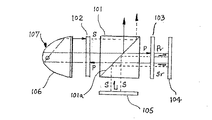
図5には、このような偏光変換光学系を備えた光源装置が示されており、この光源装置の偏光変換光学系は、光源光軸上に配置された偏光ビームスプリッタ101を挟み、入射側に配置された1/4波長板102、および出射側に配置された1/4波長板103と、1/4波長板103の後方に配置された全反射ミラー104と、偏光ビームスプリッタ101の下側方向に配置された全反射ミラー105とを備えている。(例えば特許文献1)
この装置では、偏光ビームスプリッタ101は光源107から出射される平行光のうちのS偏光成分を直交方向に反射し、P偏光成分をそのまま透過させる偏光分離膜101a が備わっており、光源107からの出射光は1/4波長板102を介して偏光ビームスプリッタ101に入射し、S偏光成分のみが直角に反射されて図の上方に向けて出射される。一方のP偏光成分の光は、偏光分離膜101a を通過して、反対側に配置されている1/4波長板103および反射鏡104,105と光源100の反射鏡106との間を少なくとも7回は通過し、5回は偏光ビームスプリッタ101を通過した後にS偏光成分の光となって、図の上方に出射されることとなる。その結果、これらの光学素子を通過する際に発生する光量損失や、偏光効率の劣化を無視できず、従って、偏光変換による光の利用効率の向上はあまり期待できない。
【0006】
これを改善するため、本発明者らは、検討の結果、偏光ビームスプリッタを透過したP偏光成分の光を、S偏光成分の光束と平行な方向に反射させ、この反射されたP偏光成分光の偏波面を偏光変換素子で90度回転させてS偏光成分の光束に変換させることによって偏光変換による光の利用効率の向上が図れることを見出し、提案した。(例えば、特許文献2)
しかし、この構造によれば、P偏光成分が1回偏光ビームスプリッタと偏光変換素子を透過するだけなので、光の利用効率が改善されるものの偏光変換素子を透過した光とそうでない光とにおいて光の均質性に問題があり、照明ムラが生じ易い問題があった。
【0007】
【特許文献1】
特開平8−29734号公報
【特許文献2】
特開2002−341291号公報
【0008】
【発明が解決しようとする課題】
本発明は、このような問題点を解決しようとするもので、液晶プロジェクタなどの照明装置において使用される偏光光源として、上述の本発明者らの提案に係る偏光光源装置において、インテグレータ・ロッドと組み合わせ使用することにより、偏光変換を光量の損失や偏光効率の低下を招くことなく、液晶パネル等への照明の均一化と高輝度化を図り、液晶ライトバルブ上における照明ムラを低減した偏光光源装置を提供することを目的とする。
【0009】
【課題を解決するための手段】
本発明は、第1の発明として、第1の発光管およびこの発光管からの発散光を射出開口部に向けて反射する第1の反射鏡を備えた第1の光源と、前記第1の反射鏡からの出射光に含まれる偏波方向が直交する二つの直線偏光光の一方を反射し、他方を透過する第1の偏光分離素子と、前記第1の偏光分離素子で反射された直線偏光光を、当該第1の偏光分離素子を透過した直線偏光光の進行方向と平行な方向に反射するかまたは、前記第1の偏光分離素子を透過した直線偏光光を、当該第1の偏光分離素子で反射された直線偏光光の進行方向と平行な方向に反射する第1の反射素子と、前記第1の偏光分離素子または、前記第1の反射素子に取り付けられ、前記第1の偏光分離素子を透過した直線偏光光の偏波面、または、前記第1の偏光分離素子で反射された直線偏光光の偏波面のどちら一方を90度回転させて他方の直線偏光光と同一成分になるように変換する第1の偏光変換素子と前記第1の偏光変換素子を透過せず、変換されない直線偏光光と前記第1の偏光変換素子により変換された直線偏光光との二つの偏光光を入射する第1のインテグレータ・ロッドと当該インテグレータ・ロッドから射出された光束を所定の画面寸法に導くための光学素子とを有していることを特徴とするとすることによって、前記第1の偏光変換素子により変換された直線偏光光と他方の直線偏光光との二つの偏光光をインテグレータ・ロッドで混合合成して均質な偏光光として照度ムラの少ない偏光光源装置を提供しようとするものである。
【0010】
本発明の第2発明としては、前記第1の発明記載の偏光光源装置において、前記第1の偏光分離素子に対して前記第1の光源と対向状態に配置された第2の発光管および当該第2の発光管からの発散光を第2の射出開口部に向けて反射する第2の反射鏡を備えた第2の光源と、前記第1の偏光分離素子と併設され、前記第2の反射鏡からの出射光に含まれる偏波方向が直交する二つの直線偏光光の一方を、前記第1の偏光分離素子によって反射される直線偏光光と同一成分でかつ同一方向に反射し、前記第1偏光分離素子を透過する直線偏光光と同一方向でかつ同一成分の他方の直線偏光光を透過する第2の偏光分離素子と、前記第2の偏光分離素子で反射された直線偏光光を、当該第2の偏光分離素子を透過した直線偏光光の進行方向と平行な方向に反射するかまたは、前記第2の偏光分離素子を透過した直線偏光光を、当該第2の偏光分離素子で反射された直線偏光光の進行方向と平行な方向に反射する第2の反射素子と、前記第2の偏光分離素子または、前記第2の反射素子にとりつけられ、前記第2の偏光分離素子を透過した直線偏光光の偏波面、または、前記第2の反射素子で反射された直線偏光光の偏波面のどちらか一方を90度回転させて他方の直線偏光光と同一成分になるように変換する第2の偏光変換素子と前記第1の偏光変換素子を透過せず、変換されない直線偏光光と前記第1の偏光変換素子により変換された直線偏光光からなる第1の対をなす直線偏光光と、前記第1の対をなす直線偏光光と同一成分をなし、前記第2の偏光変換素子を透過せず、変換されない直線偏光光と前記第2の偏光変換素子により変換された直線偏光光からなる第2の対をなす直線偏光光の少なくとも1対の偏光光を前記第1のインテグレータ・ロッドに入射することを特徴とする偏光光源装置とすることによって、2個の光源を使用し、より高輝度で照明ムラの少ない偏光光源装置を提供しようとするものである。
【0011】
本発明の第3の発明としては、前記第2の発明記載の偏光光源装置において、前記第1の対をなす直線偏光光と第2の対をなす直線偏光光の2対の直線偏光光を、第1のインテグレータ・ロッドに入射し、第1のインテグレータ・ロッドから射出された光束を所定の画面寸法に導くための光学素子に入射することを特徴とする偏光光源装置とすることにより、より高輝度で照明ムラが少なく、小型の偏光光源装置を提供しようとするものである。
【0012】
本発明の第4の発明としては、前記第2の発明記載の偏光光源装置において、前記第1のインテグレータ・ロッドに併設して第2のインテグレータ・ロッドを配設し、第1のインテグレータ・ロッドに、第1の対をなす直線偏光光を、第2のインテグレータ・ロッドに、第2の対をなす直線偏光光を入射し、各インテグレータ・ロッドから射出された光束を所定の画面寸法に導くための光学素子に入射することを特徴とする偏光光源装置とすることにより、より均質な偏光光を出射可能とする偏光光源装置を提供しようとするものである。
【0013】
本発明の第5の発明としては、前記第1の偏光分離素子または第1及び第2の偏光分離素子と第1のインテグレータ・ロッドまたは第1及び第2のインテグレータ・ロッドとの間に、前記第1の対をなす直線偏光光または前記第1及び第2の対をなす直線偏光光を前記第1のインテグレータ・ロッドまたは各インテグレータ・ロッドの入射開口部に収束させるための集光光学系を配置した前記第1の発明から第4の発明のいずれかに記載された偏光光源装置とすることによって、ライトバルブに対する照射効率を改善できる偏光光源装置を提供しようとするものである。
【0014】
本発明の第6の発明としては、前記第1の光源と第1の偏光分離素子との間、または第2の光源と第2の偏光分離素子との間に、前記各光源の射出開口から放出される射出光束を平行光束にする平行光束形成光学系を配置した前記第1から第5の発明のいずれかに記載された偏光光源装置とすることによって、各光源から射出される光束を無駄なく偏光分離素子に入射可能となり、光の利用効率を高めることのできる偏光光源装置を提供しようとするものである。
【0015】
本発明の第7の発明としては、第1の発光管および当該第1の発光管からの発散光を第1の射出開口部から収束するように反射する第1の反射鏡を備えた第1の光源と、前記第1の反射鏡によって収束する光束結像点に入射開口部を有する第1のインテグレータ・ロッドを配置し、前記第1のインテグレータ・ロッドからの出射光に含まれる偏波方向が直交する二つの直線偏光光の一方を反射し、他方を透過する第1の偏光分離素子と、この偏光分離素子で反射された直線偏光光を、当該第1の偏光分離素子を通過した直線偏光光の進行方向と平行な方向に反射するかまたは、前記第1の偏光分離素子を透過した直線偏光光を、当該第1の偏光分離素子で反射された直線偏光光の進行方向と平行な方向に反射する第1の反射素子と、前記第1の偏光分離素子または、前記第1の反射素子に取り付けられ、前記第1の偏光分離素子を透過した直線偏光光の偏波面、または、前記第1の偏光分離素子で反射された直線偏光光の偏波面のどちらか一方を90度回転させて他方の直線偏光光と同一成分になるように変換する第1の偏光変換素子と前記第1の偏光変換素子を透過せず、変換されない直線偏光光と前記第1の偏光変換素子により変換された直線偏光光との二つの偏光光を入射して、所定の画面寸法に導くための光学素子を有していることを特徴とする偏光光源装置とすることによって、光源中に含まれるノイズ成分を減少させて偏光分離素子における分離効率を改善して、照度ムラの少ない偏光光源装置を提供しようとするものである。
【0016】
本発明の第8の発明としては、第7の発明記載の偏光光源装置において、前記第1の偏光分離素子に対して前記第1の光源と対向状態に配置された第2の発光管および当該第2の発光管からの発散光を第2の射出開口部に向けて反射する第2の反射鏡を備えた第2の光源と、前記第2の反射鏡によって収束する光束による結像点に入射開口部を有する第2のインテグレータ・ロッドを配置し、前記第1の偏光分離素子と併設され、前記第2のインテグレータ・ロッドからの出射光に含まれる偏波方向が直交する二つの直線偏光光の一方を、前記第1の偏光分離素子によって反射される直線偏光光と同一成分でかつ同一方向に反射し、前記第1偏光分離素子を透過する直線偏光光と同一方向でかつ同一成分の他方の直線偏光光を透過する第2の偏光分離素子と、前記第2の偏光分離素子で反射された直線偏光光を、当該第2の偏光分離素子を透過した直線偏光光の進行方向と平行な方向に反射するかまたは、前記第2の偏光分離素子を透過した直線偏光光を、当該第2の偏光分離素子で反射された直線偏光光の進行方向と平行な方向に反射する第2の反射素子と、前記第2の偏光分離素子または、前記第2の反射素子に取り付けられ、前記第2の偏光分離素子を透過した直線偏光光の偏波面、または、前記第2の偏光分離素子で反射された直線偏光光の偏波面のどちらか一方を90度回転させて他方の直線偏光光と同一成分になるように変換する第2の偏光変換素子と前記第1の偏光変換素子を透過せず、変換されない直線偏光光と前記第1の偏光変換素子により変換された直線偏光光からなる第1の対をなす直線偏光光と、前記第1の対をなす直線偏光光と同一成分をなし、前記第2の偏光変換素子を透過せず、変換されない直線偏光光と前記第2の偏光変換素子により変換された直線偏光光からなる第2の対をなす直線偏光光の少なくとも1対の偏光光を入射して、所定の画面寸法に導くための光学素子を有していることを特徴とする偏光光源装置とすることによって、光源中に含まれるノイズ成分を減少させて偏光分離素子における分離効率を改善して、照度ムラの少なく、高輝度の偏光光源装置を提供しようとするものである。
【0017】
本発明においては、液晶プロジェクターなどのように特定の偏光成分からなる偏光光束を照明光として使用する場合に用いられる偏光光源装置において、メタルハライドランプ等のアークランプやハロゲンランプ等の発光管および当該発光管からの発散光を射出開口部に向けて反射する反射鏡を備えた光源を使用し、この光源の射出開口部から放出される射出光束を断面が偏光分離素子の入射開口部の寸法にほぼ一致する平行光束にする平行光束形成光学系を配置し、この平行光束に含まれる偏波方向が直交する二つの直線偏光光の中、P偏光成分を反射し、S偏光成分を透過する偏光ビームスプリッタ等の偏光分離素子と、偏光分離素子で反射されたP偏光成分の直線偏光光を、当該偏光分離素子を透過したS偏光成分の直線偏光光の進行方向と平行な方向に反射するかまたは、前記偏光分離素子を透過したS偏光成分の直線偏光光を、当該偏光分離素子で反射されたP偏光成分の直線偏光光の進行方向と平行な方向に反射する反射素子を使用し、この反射素子で反射されたP偏光成分の直線偏光光の偏波面を90度回転させて偏光分離素子を透過したS偏光成分の直線偏光光と同一成分になるように変換する偏光変換素子を前記反射素子の後方に配置する構造とすると、S偏光成分の直線偏光光を偏光変換素子を透過させることなく利用できるので、偏光変換素子による光の損失を抑制できることになり、S偏光成分で作動するライトバルブを使用するときには、好適である。
【0018】
本発明の第1から第6までの発明では、偏光変換素子を透過せず、変換されない直線偏光光と偏光変換素子を透過した直線偏光光とは、基本的には同一成分であるが、わずかな相違が生じる場合が有り得、これらの直線偏光光を直接ライトバルブに照射すると、これらの直線偏光光の照射部分によって、照度が相違するなどの不具合を生じる場合があり得るが、これらの直線偏光光が第1及び第2のインテグレータ・ロッドを通過することによって、これらの直線偏光光が適当に混合合成され、均質な出射光となり、照明ムラを良好に抑制することができる。
【0019】
これらのインテグレータ・ロッドは、1個または複数個であってもよいが、特に第1の光源と第2の光源の2つの光源を使用し、それぞれの光源からの光束を偏光変換素子を透過せず変換されない直線偏光光と偏光変換素子を透過して得られる直線偏光光とからなる第1及び第2の対をなす直線偏光光に対応して、それぞれに、第1及び第2のインテグレータ・ロッドを配設すれば、より適切な混合合成が行われるので、好ましい。
【0020】
さらに、偏光分離素子を透過した直線偏光光と偏光変換素子を透過して得られる直線偏光光は、一般に、光軸に対し平行光束となっているので、これらの平行光束を集光レンズを使用して、前記インテグレータ・ロッドの入射開口部に収束させれば、光束の損失が少なくなるので好適である。
【0021】
また、光源からの発散光を直接偏光分離素子に出射して、偏光分離素子での分離、偏光変換素子を介しての変換によってS偏光成分の直線偏光光とされるが、この際、これの偏光光に楕円光成分が含まれる場合があり、この楕円光成分は、ライトバルブでの変換効率を低下させるので、この楕円光成分を極力除去することが好ましい。本発明の第7及び第8発明では、この楕円光成分が光源からの発散光を偏光分離素子に出射する際に、これらの間に、第1または、第1及び第2のインテグレータ・ロッドを介したとき、楕円光成分が減少して変換効率が改善されることを見出し、本発明を完成させた。
【0022】
本発明の偏光光源装置においては、光源からの射出光束における一方の直線偏光成分は、偏光分離素子を1回通り、他方の直線偏光成分は偏光分離素子、および偏光変換素子をそれぞれ1回ずつ通るのみである。従って、偏光変換を光量損失や偏光変換効率の低下を招くことなく行うことができる。
【0023】
本発明における各々の偏光分離素子は、光源光軸に対し、45度傾斜した偏光分離膜を備えたプリズム合成体、またはミラーとすることができる。この偏光分離膜の構成によって、S偏光成分を透過し、P偏光成分をするか、または、逆にP偏光成分を透過するか、S偏光成分を反射するかを選択し、ライトバルブが作動する成分によって適宜選択することができる。このライトバルブの作動成分等によって、偏光変換が必要とされる偏光成分が決定され、この決定に基づき、偏光変換素子を偏光分離素子を通過した光束に対して配置するか、偏光分離素子で反射された光束に対して配置するか決定される。このような偏光変換素子としては、1/2波長板が好適に使用できる。
【0024】
同様に、各々の反射素子においても前記光軸に対して、45度傾斜した全反射プリズム、ミラー、あるいは45度傾斜した全反射膜を有するプリズム合成体とすることができる。
【0025】
本発明においては、偏光分離素子に入射される光線は、光源光軸と平行な平行光線であることが好ましいが、反射鏡の形状によって平行光線を形成することが困難な場合があり、そのような場合には、反射鏡と偏光分離素子との間に、凹レンズ等の平行光束形成光学系を配置して偏光分離素子に適切に平行光線が入射されることが好ましい。
【0026】
また、偏光光源装置による照明対象は、一般に横長の矩形形状をしているため、前記のそれぞれの偏光分離素子を構成しているプリズム合成体、並びに、反射素子を構成しているプリズム合成体を照明領域に対応する矩形形状となるように並列配置することが望ましい。
【0027】
本発明の偏光光源装置は、1個、または2個の光源を備えた偏光光源装置であって、偏光分離・変換光学系を小型でコンパクトに構成でき、しかも、矩形形状の照明領域を効率良く照明することができる。
【0028】
一方、偏光光源装置による照明対象の液晶ライトバルブは、一般に横長の矩形形状をしており、そのアスペクト比は4:3であり、近年においては16:9の横長のものも採用されている。従って、偏光光源装置を用いて、この様な矩形の照明領域を効率良く照明できるようにすることが望ましい。
【0029】
【発明の実施の形態】
以下に、図面を参照して、本発明を適用した偏光光源装置の実施例を説明する。
(実施例1)
図1は、矩形の液晶ライトバルブを備えた液晶プロジェクターの光源装置として用いられる偏光光源装置の一例を示す光学系の概略構成図である。また、図1の(A)は、その側面構成図、(B)は、偏光変換光学系の部分図で、(C)は、偏光変換素子を透過せず、変換されない直線偏光光と偏光変換素子を透過して変換された直線偏光光を示す図である。本例の偏光光源装置は、一つの光源を用いて、この光源に対応して設けた偏光変換光学系とを備えた偏光光源装置である。
【0030】
詳細に説明すると、本例の偏光光源装置は、発光管1および当該発光管1からの発散光を射出開口部2aに向けて反射する反射鏡2を備えた光源16である。反射鏡2の反射面は楕円面であり、射出開口部2a から射出される射出光束L12は収束光束となる。この射出光束L12は、光源光軸15と同軸状態に配置されている凹レンズ4によって平行光束L13とされる。この平行光束L13は、次に述べる偏光分離素子5の入射開口部5bに導かれる。このように、本例では、光源反射鏡2と凹レンズ4によって光源16の射出開口部2aから射出される射出光束L12を断面が偏光分離素子5の入射開口部5bの形状よりわずかに小さい所定寸法の平行光束にする平行光束形成光学系が採用されている。
【0031】
凹レンズ4から射出される平行光束L13は、偏波方向が直交する二つの直線偏光光の一方を反射し、他方を透過する偏光分離素子5の入射開口部5bに入射される。そして、本例では、この偏光分離素子5は2個の直角プリズムによって構成され、平行光束L13に対して45度傾斜した偏光分離膜5aを備えたプリズム合成体である。また、図1(B)にて判るように、本例では、偏光分離膜5aによってS偏光光が透過され、P偏光光は当該偏光分離膜5aによって反射されるようになっている。
【0032】
この偏光分離膜5aで反射したP偏光光は、反射素子6である全反射プリズムに入り、45度傾斜した面6aにより、当該偏光分離素子5で透過したS偏光光の進行方向と平行な方向に反射される。この場合、偏光変換素子7は、この例のように、必ずしも反射素子6の出射面に直接貼り付けることなく、前記出射面に近接させて保持部材によって取り付けることもできる。
【0033】
また、反射素子6における出射面には、当該反射素子6で反射されたP偏光光をS偏光光に変換するための偏光変換素子7が貼り付けられている。本例の偏光変換素子7は1/2波長板である。なお、この偏光変換素子7を偏光分離素子5のS偏光光の出射面に貼り付けて、S偏光光をP偏光光に変換することもできる。
【0034】
つぎに、本発明の偏光光源装置1では、図1(C)より判るように、偏光分離素子7を透過したS偏光光Sの光束L14aと、偏光分離素子5偏光分離膜5a にて反射し、全反射プリズム6を経て、当該全反射プリズムの出射面に貼り付けられている偏光変換素子7により変換されたS偏光光S'によって形成されるL14bの1対の直線偏光光からなる面光源は矩形形状を呈している。
【0035】
そして、この二つの偏光光L14aとL14bは、集光レンズである凸レンズ8によってインテグレータ・ロッド9の入射開口部9aに収束されて導かれ、インテグレータ・ロッド9によって均一化された偏光光はインテグレータ・ロッド9から射出し、集光凸レンズ10により液晶ライトバルブAの所定画面寸法に照射される。なお図1(A)中、3は、赤外線や紫外線等の特定の波長をカットする波長限定フィルターである。
【0036】
このようにして液晶ライトバルブに照射されたS偏光光は、インテグレータ・ロッドのないものに比べ、偏光変換による光の利用効率を低下させることなく、照射ムラが少なく、改善されていることが確認された。
【0037】
(実施例2)
図2は、本発明による他の実施例の概略構成図を示す。実施例1の偏光光源装置1において、一つの光源16としたものであるが、この実施例2では、これに対し、光源を二つ使用しており、基本的には、その他の構成は実施例1と同様である。図2(A)は、その側面構成図であり、(B)は、集光凸レンズ45とインテグレータ・ロッド46と集光凸レンズ47を除いて図2(A)の下方から見た平面構成図を示し、(C)は、図(B)の偏光変換光学系の部分構成図である。
【0038】
本例の偏光光源装置2の1つの光源16を使用した場合の基本構成について図2(A)により説明すると、発光管21および当該発光管21からの発散光を射出開口部22aに向けて反射する反射鏡22を備えた第1の光源36を備えている。反射鏡22の反射面は楕円面であり、射出開口部22a から射出される第1の出射光束L32は収束光束となる。この出射光束L32は光源光軸25と同軸状態に配置されている凹レンズ24によって平行光束L33とされる。この平行光束L33は、つぎに述べる偏光分離素子15の入射開口部15bに収まる断面寸法とされる。このように、本例では、反射鏡22と凹レンズ24によって第1の光源36の射出開口部22a から射出される第1の出射光束L32を断面が所定寸法の平行光束にする第1の平行光束形成光学系が構成されている。
【0039】
凹レンズ24から出射される平行光束L33は、偏波方向が直交する二つの直線偏光光の一方を反射し、他方を透過する第1の偏光分離素子15は、2個の直角プリズムで構成され、平行光束L33に対して45度傾斜した偏光分離膜15a によってP偏光光が反射され、S偏光光は当該偏光分離膜15a をそのまま透過するようになっている。
【0040】
図2(A)で示すように、この第1の偏光分離素子15の右側面側には第1の偏光分離素子15を透過した直線偏光光であるS偏光光を、当該第1の偏光分離素子15で反射されたP偏光光の進行方向と平行な方向(図2(A)の下方)に反射する第1の反射素子16が配置されている。本例では、この第1の反射素子16は直角プリズムによる45度の全反射プリズムとしている。このように、直方体状の偏光分離素子15と同形状の反射素子16を使用した場合には、これらの素子の取り付けが容易となって好ましいが、この反射素子16は、この例で示すように、2個の直角プリズムで構成し、前記平行光束に対して45度傾斜した全反射膜16aを備えたプリズム合成体としてもよいが、45度の傾斜を持たせた全反射ミラーとしてもよい。
【0041】
また、第1の偏光分離素子15の偏光分離膜15aにて反射されたP偏光光は、第1の偏光分離素子15の出射面に貼り付けられている第1の偏光変換素子17によって、S偏光光に変換される。本例の第1の偏光変換素子17は1/2波長板である。なお、この第1の偏光変換素子17を第1の反射素子16の出射面に貼り付けてS偏光光をP偏光光に変換することもできる。
【0042】
次に、本例の偏光光源装置2は、図2(A)から明らかなように、上記の第1の光源36を使用した場合と基本的には同一構成の第2の光源56および第2の偏光分離素子19と第2の反射素子20と第2の偏光変換素子18からなる第2の偏光変換光学系を備えており、第2の光源56は、第1の偏光分離素子15に対し第1の光源36と対向し、その光軸45が第1の光源36の光軸25と図2(A)の上方から見た場合(図2(B)参照)、平行にずれた状態に配設され、第2の偏光変換光学系は、前記第1の偏光分離素子15と第1の反射素子16と第1の偏光変換素子17からなる第1の偏光変換光学系と併設されており、2(B)の平面構成図から明らかなように、第1および第2の光学系は点O を中心として点対称の状態に、即ち、直方体の第1の偏光分離素子15の右側面に直方体の第1の反射素子16を、この第1の反射素子16の背面に同形状の第2の偏光分離装置18を、また第1の偏光分離装置15の背面に同形状の第2の反射素子20取り付けられて、配置されている。
【0043】
すなわち、発光管41および当該発光管41から発散光を射出開口部42aに向けて反射する反射鏡42を備えた第2の光源56を備えている。反射鏡42の反射面は楕円面であり、射出開口部42aから射出される第2の出射光束L52は収束光束となる。この出射光束L52は、光源光軸45と同軸状態に配置されている凹レンズ44によって平行光束L53とされる。
【0044】
凹レンズ44から出射される平行光束L53は、偏波方向が直交する二つの直線偏光光の一方を反射し、他方を透過する第2の偏光分離素子18に入射する。本例においては、この第2の偏光分離素子18は、2個の直角プリズムから構成され、平行光束L53に対して45度傾斜した偏光分離膜18aを備えたプリズム合成体である。このプリズム合成体に換わって偏光分離膜を有する45度傾斜したミラーとしてもよい。また、本例では、偏光分離膜18aによってP偏光光が反射されて図2(A)の下方に出射され、S偏光光は当該偏光分離膜18aをそのまま透過するようになっている。
【0045】
この第2の偏光分離素子18の背面側(図2(B)の左側)には、第2の偏光分離素子18を透過した直線偏光光であるS偏光光を、当該第2の偏光分離素子18で反射されたP偏光光の進行方向と平行な方向に反射する第2の反射素子20が配置されている。本例では、この第2の反射素子20は直角プリズムを用いて、平行光束に対して45度の全反射プリズムとしている。この第2の反射素子20は、45度傾斜させた全反射ミラーか、または2個の直角プリズムで構成し、平行光束L53に対して45度傾斜した全反射膜20aとするプリズム合成体とすることができる。
【0046】
また、第2の偏光分離素子18には、第2の偏光分離素子18の偏光分離膜18aにおいて、反射されたP偏光光をS偏光光に変換するための第2の偏光変換素子19が貼り付けられており、本例においては、この第2の偏光変換素子19を1/2波長板としている。なお、図中、23と43は、前述の波長限定フィルターである。
【0047】
このように構成した本例の偏光光源装置2では、図2(A)および図2(B)から判るように、片側が直角な面を有した梯形体形状、または2個の直角プリズムを貼り合わせて構成した直方体形状をした第1および第2の偏光分離素子15,18、並びに第1および第2の反射素子16,20が、照明対象の液晶ライトバルブの照明領域A に対応するよう図2(C)に示す矩形形状に配列されている。そして、偏光方向がS偏光成分として揃った同一断面形状の直線偏光光が出射され、集光レンズ45によって1個の第1のインテグレータ・ロッド46の入射開口部46aに導かれ、インテグレータ・ロッド46によって均質化した光束とし、集光レンズ47によって照明領域A を照射する。ここで、インテグレータ・ロッドの形状は、円柱、または角柱のものを使用できるが、取り付け等の上から角柱が望ましい。
【0048】
以上のように、第1および第2の光源36,56からの出射光束L32,L52の断面を、偏光分離素子15,18の入射開口部15b、18bに収まるように縮小しているので、光量損失を抑え、偏光効率の低下を抑制できる。また、出射光束L32,L52は、偏光分離素子15,18、偏光変換素子17,19を1回通過するだけなので、この点においても光量損失および偏光効率の低下を抑制できる。さらに第1の偏光分離素子15を透過するS偏光成分(S1)と第1の偏光分離素子15で反射されたP偏光成分を第1の偏光変換素子17で変換されたS偏光成分(S2)とからなる第1の対をなす直線偏光光及び第2の偏光分離素子18を透過するS偏光成分(S3)と第2の偏光分離素子18で反射されたP偏光成分を第2の偏光変換素子19で変換されたS偏光成分(S4)とからなる第2の対をなす直線偏光光とを1個の第1のインテク゛レータ・ロッド46に入射して照射領域Aに出射するので、S1、S2、S3、S4の直線偏光光が適切に混合合成され、均質なS偏光成分の偏光光を照射領域Aに出射することができ、照射ムラの少ない光源となる。
【0049】
また、偏光変換された後の出射光束は、照明領域Aに対応する形状となっているので、矩形の液晶ライトバルブを効率よく照明することができる。
【0050】
加えて、インテグレータ・ロッドとプリズム合成体を用いた偏光変換光学系とすることによって、小型でコンパクトな構成とすることができるので、装置の小型化を実現できる。
【0051】
なお、この実施例では、2個の光源36及び56を用いて高輝度の光源装置としているが、当然、1個の光源、偏光分離素子、反射素子及び偏光変換素子を使用しても所期の効果は十分に達成することができる。
【0052】
(実施例3)
図3には、もう一つの他の実施例の概略構成図を示している。
2組の光源と各光源に対応して設けた2組の偏光変換光学系とを備えた2光源型の偏光光源装置において、前記実施例2では、偏光変換された直線偏光光を一つの集光レンズ45によって、インテグレータ・ロッド46の入射開口部に導くよう構成しているが、本例においては、集光レンズ45を用いることなく、2組の偏光分離素子65,75、偏光変換素子67,77、および反射素子66,76によって偏光変換された光束を、2組の偏光分離素子65,75および反射素子66,76によって形成される出射光束の断面寸法、すなわち、図2(C)に示すような入射開口部68aとなるようにした一個のインテグレータ・ロッド68に入射させて、光束の均質化を図り、インテグレータ・ロッド68から出射した光束を集光レンズ69によって照明領域Aを照明するようにしている。なお、本実施例では、図3のインテグレータ・ロッド68及び集光レンズ69を除いた下方から見た平面図は、図2(B)と同一なので、省略したが、図3の第1の偏光分離素子65及び第1の反射素子66の背部にそれぞれ第2の反射素子(図3では、全反射膜76aで表示している。)と第2の偏光分離素子(図3では、偏光分離膜75aで表示している。)が取り付けられている。図中、63と73は、前述の波長限定フィルターである。
【0053】
また、この実施例では、インテグレータ・ロッド68は、1個のみを使用し、第1の反射素子66及び第1の偏光変換素子66から出射された第1の対のS偏光成分の直線偏光光と第2の反射素子76及び第2の偏光変換素子77から出射された第2の対のS偏光成分の直線偏光光の両方の直線偏光光をインテグレータ・ロッド68の入射開口部68aに入射させたが、2個の第1及び第2のインテグレータ・ロッドを使用し、第1の偏光変換系から出射された第1の対のS偏光成分の偏光光を第1のインテグレータ・ロッドに、また第2の偏光変換系から出射された第2の対のS偏光成分の偏光光を第2のインテグレータ・ロッドに入射させてもよく、さらに第1及び第2の反射素子と偏光変換素子とから出射された4種のS偏光成分の直線偏光光のそれぞれに対して4個のインテグレータ・ロッドを配置するように、複数個のインテグレータ・ロッドを使用してもよく、偏光変換された後の出射光束の断面寸法にインテグレータ・ロッドの入射開口部に合わせて、配置することが可能である。
【0054】
本例の場合には、実施例2の構成に比べて、インテグレータ・ロッド自身は大きくなるが、偏光光源装置は小型化され、コンパクトとすることができ、しかも、実施例2と同様に光量損失を抑え、偏光効率の低下を抑制できる。この場合も、1個の光源、偏光分離素子、反射素子及び偏光変換素子を使用しても所期の効果は十分に達成することができる。
【0055】
(実施例4)
この実施例では、偏光光源装置4において、2組の光源と各光源に対応した2組の偏光変換光学系を用いる2光源型の構成において、インテグレータ・ロッドを光源80及び90と第1及び第2の偏光分離素子86及び96の間にそれぞれ配置した例を示し、図4による概略構成図に基づいて説明する。
【0056】
第1の発光管81および当該発光管81からの発散光を射出開口部82aに向けて反射する反射鏡82を備えた第1の光源80を備えている。反射鏡82の反射面は楕円面であり、射出開口部82aから射出される第1の出射光束L83は収束光束となる。この収束光束L83は、光源光軸89に対して45度傾斜して配置した全反射ミラー84によって反射され、その収束部に第1のインテグレータ・ロッド85の入射開口部85aを配置してある。第1のインテグレータ・ロッド85から出射された光束は、第1のインテグレータ・ロッド85と隣接して配置されている第1の偏光分離素子86に入り、偏波方向が直交する二つの直線偏光光の一方(P偏光成分)を反射し、他方(S偏光成分)を透過する。本例では、前記の実施例2と同様にこの第1の偏光分離素子86は、2個の直角プリズムからなるプリズム合成体である。本例では、偏光分離膜86bによりP偏光光が反射され、S偏光光は当該偏光分離膜86bをそのまま透過するようになっている。
【0057】
この第1の偏光分離素子86の右側面側には第1の偏光分離素子86を透過した直線偏光光であるS偏光光を、当該第1の偏光分離素子86で反射されたP偏光光の進行方向と平行な方向に反射する第1の反射素子87が配置されている。本例では、この反射素子87は直角プリズムによる全反射プリズムからなっている。この反射素子は全反射ミラー、または全反射膜を備えたプリズム合成体とすることができる。
【0058】
また、第1の偏光分離素子86で反射されたP偏光光をS偏光光に変換するための第1の偏光変換素子88が、第1の偏光分離素子86の出射面に貼り付けられている。本例の第1の偏光変換素子88は1/2波長板である。この第1の偏光変換素子88を第1の反射素子87の出射面に貼り付けることにより、S偏光光をP偏光光に変換することができる。
【0059】
次に、本例の偏光光源装置4は、前記の実施例2と同様な構成の第2の光源および第2の偏光変換光学素子を備えており、この場合における光源80及び90と偏光分離素子86及び96と反射素子87及び97の配置は、基本的に前記実施例の図2(B)で図示する配置と同一であり、第1および第2の光学系86、87、96、97は、点O を中心として点対称の状態に配列されている。
【0060】
すなわち、第2の発光管91および当該発光管91からの発散光を射出開口部92aに向けて反射する第2の反射鏡92を備えた第2の光源90を備えている。第2の反射鏡92の反射面は楕円面であり、射出開口部92aから射出される第2の出射光束L93は収束光束となる。この出射光束L93は、光源光軸99に対して45度傾斜して配置されている全反射ミラー94によって反射され、その収束部に第2のインテグレータ・ロッド95の入射開口部95aが配置されてある。このインテグレータ・ロッド95を経て出射された光束は、第2のインテグレータ・ロッド95と隣接配置されている第2の偏光分離素子96に入り、偏波面が直交する二つの直線偏光光の一方(P偏光成分)を反射し、他方(S偏光成分)を透過する。本例では、前記の実施例2と同様に第2の偏光分離素子96は、2個の直角プリズムから構成されたプリズム合成体である。本例では、第2の偏光分離膜96bにより、P偏光光が反射され、S偏光光は当該偏光分離膜96bをそのまま透過するようになっている。
【0061】
この第2の偏光分離素子96の左側面側には第2の偏光分離素子96を透過した直線偏光光であるS偏光光を、当該第2の偏光分離素子96で反射されたP偏光光の進行方向と平行な方向に反射する第2の反射素子97が配置されている。本例では、この第2の反射素子97は直角プリズムによる全反射プリズムによって構成されている。
【0062】
また、第2の偏光分離素子96おいて、偏光分離膜96bによって反射したP偏光光の出射面には、P偏光光をS偏光光に変換する第2の偏光変換素子98が貼り付けられている。本例の第2の偏光変換素子98は1/2波長板である。
【0063】
このように構成された偏光光源装置4の偏光変換光学系は、2個の直角プリズムを貼り合わせて構成した直方体形状、または片側が直角な面を有した梯形体形状をした第1および第2の偏光分離素子86、96、並びに第1および第2の反射素子87,97が、照明対象の液晶ライトバルブの照明領域Aに対応するように、矩形上に配列されている。そして、偏光分離素子86、96、および偏光変換素子88,98によって変換された光束は、集光レンズ100によって照明領域Aに導かれるようになっている。
【0064】
本例の偏光光源装置4は、偏光変換された後の射出光束が照明領域Aに対応する形状となっているので、矩形の液晶ライトバルブを効率良く照明することが可能となる。
【0065】
さらには、プリズム合成体とインテグレータ・ロッドを用いた偏光変換光学系に1枚の集光レンズ100で照明領域Aに導くようにしたことにより、よりコンパクトで装置の小型化が実現できる。なお、この例においても1個の光源、偏光分離素子、反射素子及び偏光変換素子を使用しても所期の効果は十分に達成することができる。
【0066】
【発明の効果】
以上説明したように、本発明においては、光源からの光束を偏光変換光学系の入射開口部の大きさまで圧縮し、これを偏光分離素子および偏光変換素子を1回だけ通して偏光方向が揃った直線偏光光として、しかも、インテグレータ・ロッドを導入したことにより、照明ムラをなくし、照明効率を高めて照射領域を照射するようにした高輝度対応の偏光光源装置を実現できる。
【0067】
また、本発明においては、二つの光源と各光源からの射出光束を一つの直線偏光光に変換する二つの偏光変換光学系を備えた偏光光源装置において、上記のように高輝度化を図ると共に、プリズム合成体などからなる偏光分離素子および反射素子を用いて、矩形の照明領域に対応するように、偏光変換後の光束を出射するようにしているので、光の利用効率の高い偏光光源装置を実現できる。また、偏光変換光学系をプリズム合成体からなる偏光分離素子および反射素子を並列配置させており、あわせて、照明ムラを改善するための装置としてインテグレータ・ロッドを採用したことにより、偏光光源装置の小型化が実現できる。
【図面の簡単な説明】
【図1】本発明を適用した一つの光源を用いた実施例1の偏光光源装置を示す概略構成図で、(A)、(B)、(C)は、それぞれ、図1の偏光光源装置の側面構成図、偏光変換光学系の部分図及び偏光分離素子と偏光変換素子から出射されるS偏光成分の偏光光束を示す図である。
【図2】本発明を適用した実施例2の偏光光源装置の概略構成図で、(A)、(B)、(C)は、それぞれ、偏光光源装置の側面構成図、(A)のインテグレータ・ロッド及び集光レンズを除いて下方から見た平面構成図、および(B)の偏光変換光学系の部分平面図である。
【図3】本発明を適用した実施例3の偏光光源装置の側面構成図である。
【図4】本発明を適用した実施例4の2光源型偏光光源装置の側面構成図である。
【図5】従来の偏光光源装置の側面構成図である。
【符号の説明】
1,21,41,61,71、81,91 発光管
2,22,42,82,92 反射鏡
2a、22a、42a、82a、92a 射出開口部
3、23,43,63,73 波長限定フィルター
4,24,44,64,74 平行光束形成光学系
5,15,18,65,75,86,96 偏光分離素子
5a、15a、18a,86a、96a 偏光分離膜
5b、15b、18b、 偏光分離素子の入射開口部
6,16,20,66,76、87,97 反射素子
6a,16a,20a,66a,76a、87a,97a 全反射面
7,17,19,67,77,88,98 偏光変換素子
8,10,45,47,69,100 集光レンズ
9,46,68,85,95 インテグレータ・ロッド
9a、46a,68a,85a、95a インテグレータ・ロッドの入射開口部
L12,L32,L52,L83,L93 発散光
L13,L33,L53 平行光束
L14a 偏光分離素子を透過した光束
L14b 偏光分離膜により反射され、反射素子を経て偏光変換素子を通過した光束
84,94 反射ミラー
16,36,56,60,70,80,90 光源
15、25,45、62,72,89,99 光源光軸
A 照明領域[0001]
TECHNICAL FIELD OF THE INVENTION
The present invention relates to a polarized light source device capable of emitting a polarized light beam composed of only a specific polarized component used as a light source device for a liquid crystal projector or the like as illumination light, and more particularly, to a method in which a polarized light beam is homogenized and illumination unevenness occurs. The present invention relates to a polarized light source device having a small amount of light.
[0002]
[Prior art]
In a liquid crystal display device such as a liquid crystal projector, light emitted from a light source such as an arc lamp or a halogen lamp, such as a metal halide lamp, is applied to a light valve formed of a liquid crystal display panel, and the light valve performs modulation corresponding to a display image. Later, a projection image is formed on a projection surface via a projection optical system.
[0003]
The liquid crystal light valve that performs modulation corresponding to image information uses only a specific polarization component, and two linearly polarized light beams whose polarization directions are orthogonal even when the light emitted from the light source is directly irradiated on the liquid crystal display panel. Since one of the polarized light components is not used, the light use efficiency is low, and the projected image cannot be brightened.
[0004]
Therefore, conventionally, a light beam emitted from a light source is guided to a polarization conversion optical system, and the liquid crystal light valve is illuminated after aligning the polarization direction through the light beam. It is proposed to get it.
[0005]
FIG. 5 shows a light source device provided with such a polarization conversion optical system, and the polarization conversion optical system of the light source device sandwiches a
In this apparatus, the
[0006]
In order to improve this, the present inventors have studied and as a result, the light of the P-polarized light component transmitted through the polarizing beam splitter is reflected in a direction parallel to the light beam of the S-polarized light component, and the reflected P-polarized light component is reflected. It has been found that the polarization conversion element can be rotated by 90 degrees by a polarization conversion element and converted into an S-polarized light component to improve the light use efficiency by polarization conversion, and proposed. (For example, Patent Document 2)
However, according to this structure, since the P-polarized component only passes through the polarization beam splitter and the polarization conversion element once, light utilization efficiency is improved, but light transmitted through the polarization conversion element and light not transmitted through the polarization conversion element are improved. There is a problem in the homogeneity of the light source, and there is a problem in that uneven illumination is likely to occur.
[0007]
[Patent Document 1]
JP-A-8-29734
[Patent Document 2]
JP 2002-341291 A
[0008]
[Problems to be solved by the invention]
The present invention is intended to solve such a problem, and as a polarized light source used in an illumination device such as a liquid crystal projector, in the polarized light source device according to the above-described proposal of the present inventors, the integrator rod and A polarized light source that uses a combination to reduce the unevenness of illumination on the liquid crystal light valve by achieving uniform illumination and high brightness on the liquid crystal panel, etc., without causing loss of light quantity or reduction in polarization efficiency. It is intended to provide a device.
[0009]
[Means for Solving the Problems]
According to a first aspect of the present invention, there is provided a first light source including a first arc tube and a first reflecting mirror for reflecting divergent light from the arc tube toward an emission opening; A first polarization splitting element that reflects one of two linearly polarized light beams having orthogonal polarization directions included in the light emitted from the reflecting mirror and transmits the other, and a straight line reflected by the first polarization splitting device The polarized light is reflected in a direction parallel to the traveling direction of the linearly polarized light transmitted through the first polarization splitting element, or the linearly polarized light transmitted through the first polarization splitting element is converted into the first polarized light. A first reflection element that reflects in a direction parallel to a traveling direction of the linearly polarized light reflected by the separation element, and the first polarization separation element or the first polarization element attached to the first reflection element. The plane of polarization of the linearly polarized light transmitted through the separation element or the first polarized light component A first polarization conversion element that rotates one of the polarization planes of the linearly polarized light reflected by the element by 90 degrees to convert the polarization plane into the same component as the other linearly polarized light, and transmits through the first polarization conversion element A first integrator rod that receives two polarized lights, that is, a linearly polarized light that has not been converted and a linearly polarized light that has been converted by the first polarization conversion element, and a light beam emitted from the integrator rod is predetermined. And a linearly polarized light converted by the first polarization conversion element and the other linearly polarized light converted by the first polarization conversion element. Are mixed and synthesized with an integrator rod to provide a polarized light source device with uniform illuminance and less uneven illuminance.
[0010]
According to a second invention of the present invention, in the polarized light source device according to the first invention, a second arc tube arranged in a state facing the first light source with respect to the first polarization splitting element, and A second light source including a second reflecting mirror for reflecting divergent light from a second arc tube toward a second exit opening; and a second light source provided in parallel with the first polarization splitting element. One of the two linearly polarized lights whose polarization directions included in the light emitted from the reflecting mirror are orthogonal to each other is reflected in the same direction and in the same component as the linearly polarized light reflected by the first polarization separation element, A second polarized light separating element that transmits the other linearly polarized light having the same component and the same component as the linearly polarized light transmitted through the first polarized light separating element, and a linearly polarized light reflected by the second polarized light separating element. The traveling direction of the linearly polarized light transmitted through the second Or the linearly polarized light transmitted through the second polarization separation element is reflected in a direction parallel to the traveling direction of the linearly polarized light reflected by the second polarization separation element. A reflection element, the second polarization separation element, or a polarization plane of linearly polarized light that is attached to the second reflection element and that has passed through the second polarization separation element, or reflected by the second reflection element A second polarization conversion element that rotates one of the polarization planes of the obtained linearly polarized light by 90 degrees to convert it into the same component as the other linearly polarized light, and does not transmit through the first polarization conversion element. A first pair of linearly polarized light consisting of unconverted linearly polarized light and linearly polarized light converted by the first polarization conversion element, and the same component as the first pair of linearly polarized light, The light does not pass through the second polarization conversion element and is converted. At least one pair of polarized light of a second pair of linearly polarized light composed of the linearly polarized light and the linearly polarized light converted by the second polarization conversion element is incident on the first integrator rod. An object of the present invention is to provide a polarized light source device that uses two light sources, has higher luminance, and has less illumination unevenness, by adopting a characteristic polarized light source device.
[0011]
According to a third aspect of the present invention, in the polarized light source device according to the second aspect, two pairs of linearly polarized light of the first pair of linearly polarized light and the second pair of linearly polarized light are And a light source that is incident on the first integrator rod and is incident on an optical element for guiding a light beam emitted from the first integrator rod to a predetermined screen size. It is an object of the present invention to provide a small-sized polarized light source device with high luminance and little illumination unevenness.
[0012]
According to a fourth aspect of the present invention, in the polarized light source device according to the second aspect, a second integrator rod is provided alongside the first integrator rod, and the first integrator rod is provided. Then, the first pair of linearly polarized light is incident on the second integrator rod, and the second pair of linearly polarized light is incident on the second integrator rod, and the light flux emitted from each integrator rod is guided to a predetermined screen size. To provide a polarized light source device capable of emitting more uniform polarized light by using a polarized light source device that is incident on an optical element.
[0013]
According to a fifth aspect of the present invention, between the first polarization splitting element or the first and second polarization splitting elements and the first integrator rod or the first and second integrator rods, A condensing optical system for converging the first pair of linearly polarized light or the first and second pair of linearly polarized light to the first integrator rod or the entrance opening of each integrator rod. An object of the present invention is to provide a polarized light source device which can improve the irradiation efficiency of a light valve by using the arranged polarized light source device according to any one of the first to fourth inventions.
[0014]
According to a sixth aspect of the present invention, there is provided a device according to a sixth aspect of the present invention, in which the light source is disposed between the first light source and the first polarization splitting element or between the second light source and the second polarization splitting element. By providing the polarized light source device according to any one of the first to fifth aspects in which the parallel light beam forming optical system that converts the emitted light beam into a parallel light beam is disposed, the light beam emitted from each light source is wasted. It is an object of the present invention to provide a polarized light source device that can be incident on a polarization splitting element without increasing the light utilization efficiency.
[0015]
According to a seventh aspect of the present invention, a first light emitting tube includes a first light emitting tube and a first reflecting mirror that reflects divergent light from the first light emitting tube so as to converge from a first emission opening. And a first integrator rod having an entrance aperture at a light flux image point converged by the first reflecting mirror, and a polarization direction included in light emitted from the first integrator rod. A first polarized light separating element that reflects one of the two linearly polarized light beams orthogonal to each other and transmits the other, and a linearly polarized light beam reflected by the polarized light separating element is converted into a straight line that has passed through the first polarized light separating element. The linearly polarized light reflected in the direction parallel to the traveling direction of the polarized light or transmitted through the first polarization separation element is converted into the light parallel to the traveling direction of the linearly polarized light reflected by the first polarization separation element. A first reflecting element that reflects light in the first direction; The polarization plane of the linearly polarized light that is attached to the polarization separation element or the first reflection element and that has passed through the first polarization separation element, or the polarization plane of the linearly polarized light reflected by the first polarization separation element. A first polarization conversion element that rotates one of the wavefronts by 90 degrees and converts it into the same component as the other linearly polarized light, and a linearly polarized light that does not pass through the first polarization conversion element and is not converted. A polarized light source device comprising: an optical element for receiving two polarized lights of the linearly polarized light converted by the first polarization conversion element and leading the polarized light to a predetermined screen size. Accordingly, it is an object of the present invention to reduce the noise component contained in the light source, improve the separation efficiency in the polarization separation element, and provide a polarization light source device with less illuminance unevenness.
[0016]
According to an eighth aspect of the present invention, in the polarized light source device according to the seventh aspect of the present invention, there is provided a second light emitting tube arranged in a state facing the first light source with respect to the first polarization splitting element. A second light source including a second reflecting mirror for reflecting the divergent light from the second arc tube toward the second exit opening, and an image forming point by a light flux converged by the second reflecting mirror. A second integrator rod having an entrance opening is arranged, and two linearly polarized lights which are provided in parallel with the first polarization splitting element and whose polarization directions included in light emitted from the second integrator rod are orthogonal to each other. One of the lights is reflected in the same direction and in the same direction as the linearly polarized light reflected by the first polarization splitting element, and in the same direction and the same component as the linearly polarized light transmitted through the first polarization splitting element. The second, which transmits the other linearly polarized light A light separating element, and reflecting the linearly polarized light reflected by the second polarization separating element in a direction parallel to a traveling direction of the linearly polarized light transmitted through the second polarization separating element, or A second reflection element that reflects the linearly polarized light transmitted through the second polarization separation element in a direction parallel to the traveling direction of the linearly polarized light reflected by the second polarization separation element; and the second polarization separation element. Alternatively, either the plane of polarization of the linearly polarized light attached to the second reflection element and transmitted through the second polarization separation element, or the plane of polarization of the linearly polarized light reflected by the second polarization separation element A second polarization conversion element that rotates one of them by 90 degrees and converts it into the same component as the other linearly polarized light, and a linearly polarized light that does not pass through the first polarization conversion element and is not converted; Linearly polarized light converted by the polarization conversion element The first pair of linearly polarized light and the first pair of linearly polarized light have the same components, do not pass through the second polarization conversion element, and are not converted. Having at least one pair of linearly-polarized light of a second pair of linearly-polarized light converted by the polarization-converting element of the present invention, which is incident thereon, and leading to a predetermined screen size. By providing a polarized light source device characterized by the following, the noise component contained in the light source is reduced, the separation efficiency in the polarized light separating element is improved, and the polarized light source device with less illuminance unevenness and high luminance is provided. Things.
[0017]
In the present invention, in a polarized light source device used when a polarized light beam composed of a specific polarized component is used as illumination light, such as a liquid crystal projector, an arc tube such as a metal halide lamp or a halogen lamp or the like, A light source equipped with a reflecting mirror for reflecting the divergent light from the tube toward the exit opening is used. The cross section of the exit light flux emitted from the exit opening of this light source is approximately the size of the entrance opening of the polarization splitting element. A parallel light beam forming optical system is arranged to make the parallel light beams coincide with each other, and a polarized beam that reflects the P-polarized light component and transmits the S-polarized light component among the two linearly polarized light beams whose polarization directions are orthogonal to each other. A polarization separation element such as a splitter, and the linearly polarized light of the P polarization component reflected by the polarization separation element, and the traveling direction of the linearly polarized light of the S polarization component transmitted through the polarization separation element. Reflected in a parallel direction, or reflected in the direction parallel to the traveling direction of the linearly polarized light of the P-polarized component reflected by the polarization-separating element, the linearly polarized light of the S-polarized component transmitted through the polarization-separating element. Using a reflective element, rotate the plane of polarization of the linearly polarized light of the P-polarized light component reflected by this reflective element by 90 degrees and convert it to the same component as the linearly polarized light of the S-polarized light component transmitted through the polarization separation element. When the polarization conversion element to be disposed is arranged behind the reflection element, the linearly polarized light of the S polarization component can be used without transmitting the polarization conversion element, so that light loss due to the polarization conversion element can be suppressed, This is preferred when using a light valve that operates with an S-polarized component.
[0018]
In the first to sixth aspects of the present invention, the linearly polarized light that has not passed through the polarization conversion element and is not converted and the linearly polarized light that has passed through the polarization conversion element have basically the same components, If these linearly polarized light beams are directly radiated to the light valve, there may be a problem such as a difference in illuminance depending on the irradiated portion of these linearly polarized light beams. When the light passes through the first and second integrator rods, these linearly polarized lights are appropriately mixed and synthesized, and the emitted light becomes uniform, so that illumination unevenness can be favorably suppressed.
[0019]
One or a plurality of these integrator rods may be used. In particular, two light sources, a first light source and a second light source, are used, and light beams from the respective light sources are transmitted through the polarization conversion element. The first and second integrators respectively correspond to first and second pairs of linearly polarized light consisting of linearly polarized light that is not converted and linearly polarized light that is obtained by passing through a polarization conversion element. Arranging the rods is preferable because more appropriate mixed synthesis is performed.
[0020]
In addition, linearly polarized light transmitted through the polarization splitter and linearly polarized light obtained through the polarization converter are generally parallel to the optical axis. Then, it is preferable to converge on the entrance opening of the integrator rod because the loss of the light beam is reduced.
[0021]
In addition, the divergent light from the light source is directly emitted to the polarization separation element, separated by the polarization separation element, and converted into linearly polarized light of the S polarization component by conversion through the polarization conversion element. In some cases, the polarized light contains an elliptical light component. Since the elliptical light component lowers the conversion efficiency in the light valve, it is preferable to remove the elliptical light component as much as possible. According to the seventh and eighth aspects of the present invention, when the elliptical light component emits divergent light from the light source to the polarization splitting element, the first or first and second integrator rods are interposed between them. It has been found that when the light passes through, the elliptic light component is reduced and the conversion efficiency is improved, and the present invention has been completed.
[0022]
In the polarized light source device of the present invention, one linearly polarized light component of the light beam emitted from the light source passes through the polarization splitting element once, and the other linearly polarized light component passes through the polarization splitting element and the polarization conversion element once each. Only. Therefore, the polarization conversion can be performed without causing a loss of light amount or a decrease in polarization conversion efficiency.
[0023]
Each polarized light separating element in the present invention can be a prism composite or a mirror provided with a polarized light separating film inclined at 45 degrees to the optical axis of the light source. Depending on the configuration of the polarization separation film, the light valve operates by selecting whether to transmit the S-polarized component and transmit the P-polarized component, or to transmit the P-polarized component or reflect the S-polarized component. It can be appropriately selected depending on the components. The polarization component requiring polarization conversion is determined by the operation component of the light valve, and based on this determination, the polarization conversion element is disposed with respect to the light beam passing through the polarization separation element or reflected by the polarization separation element. It is determined whether to arrange the light beam. As such a polarization conversion element, a half-wave plate can be suitably used.
[0024]
Similarly, each reflecting element can also be a total reflection prism or mirror inclined at 45 degrees with respect to the optical axis, or a prism composite having a total reflection film inclined at 45 degrees with respect to the optical axis.
[0025]
In the present invention, the light beam incident on the polarization separation element is preferably a parallel light beam parallel to the optical axis of the light source, but it may be difficult to form a parallel light beam depending on the shape of the reflecting mirror. In such a case, it is preferable that a parallel light beam forming optical system such as a concave lens is arranged between the reflecting mirror and the polarization splitting element so that parallel rays are appropriately incident on the polarization splitting element.
[0026]
In addition, since the object to be illuminated by the polarized light source device generally has a horizontally long rectangular shape, the prism composites constituting the respective polarization splitting elements, and the prism composites constituting the reflecting elements are referred to as prism composites. It is desirable to arrange them in parallel so as to have a rectangular shape corresponding to the illumination area.
[0027]
The polarized light source device of the present invention is a polarized light source device provided with one or two light sources, and can configure the polarization separation / conversion optical system in a small and compact form, and can efficiently provide a rectangular illumination area. Can be illuminated.
[0028]
On the other hand, a liquid crystal light valve to be illuminated by a polarized light source device generally has a horizontally long rectangular shape, and its aspect ratio is 4: 3. In recent years, a 16: 9 horizontally long one has been adopted. Therefore, it is desirable to efficiently illuminate such a rectangular illumination area using a polarized light source device.
[0029]
BEST MODE FOR CARRYING OUT THE INVENTION
Hereinafter, embodiments of the polarized light source device to which the present invention is applied will be described with reference to the drawings.
(Example 1)
FIG. 1 is a schematic configuration diagram of an optical system showing an example of a polarized light source device used as a light source device of a liquid crystal projector having a rectangular liquid crystal light valve. 1 (A) is a side view of the configuration, FIG. 1 (B) is a partial view of a polarization conversion optical system, and FIG. 1 (C) is linear polarization light which is not transmitted through a polarization conversion element and is not converted. It is a figure which shows the linearly polarized light which permeate | transmitted the element and was converted. The polarized light source device of the present example is a polarized light source device including a single light source and a polarization conversion optical system provided corresponding to the light source.
[0030]
More specifically, the polarized light source device of the present embodiment is a
[0031]
The parallel light beam L13 emitted from the
[0032]
The P-polarized light reflected by the
[0033]
A polarization conversion element 7 for converting P-polarized light reflected by the
[0034]
Next, in the polarized light source device 1 of the present invention, as can be seen from FIG. 1C, the luminous flux L14a of the S-polarized light S transmitted through the polarized light separating element 7 and reflected by the polarized
[0035]
Then, the two polarized lights L14a and L14b are converged and guided to the entrance opening 9a of the integrator rod 9 by the convex lens 8 which is a condenser lens, and the polarized lights uniformized by the integrator rod 9 are integrated by the integrator rod 9. The light exits from the rod 9 and is irradiated onto a predetermined screen size of the liquid crystal light valve A by the converging
[0036]
It was confirmed that the S-polarized light irradiated to the liquid crystal light valve in this way had less irradiation unevenness and was improved without lowering the light use efficiency by polarization conversion, compared to the case without the integrator rod. Was done.
[0037]
(Example 2)
FIG. 2 shows a schematic configuration diagram of another embodiment according to the present invention. In the polarized light source device 1 of the first embodiment, one
[0038]
The basic configuration of the polarized
[0039]
The parallel light beam L33 emitted from the
[0040]
As shown in FIG. 2A, on the right side of the first
[0041]
The P-polarized light reflected by the polarization separation film 15a of the first
[0042]
Next, as is clear from FIG. 2A, the polarized
[0043]
That is, a second
[0044]
The parallel light beam L53 emitted from the
[0045]
On the back side (left side in FIG. 2B) of the second
[0046]
A second polarization conversion element 19 for converting P-polarized light reflected by the polarization separation film 18a of the second
[0047]
In the polarized
[0048]
As described above, the cross sections of the outgoing light beams L32 and L52 from the first and second
[0049]
Further, since the emitted light beam after the polarization conversion has a shape corresponding to the illumination area A, the rectangular liquid crystal light valve can be efficiently illuminated.
[0050]
In addition, by using a polarization conversion optical system using an integrator rod and a prism composite, a compact and compact configuration can be achieved, so that the device can be downsized.
[0051]
In this embodiment, a high-brightness light source device is formed by using two
[0052]
(Example 3)
FIG. 3 shows a schematic configuration diagram of another embodiment.
In the two-light source type polarized light source device provided with two sets of light sources and two sets of polarization conversion optical systems provided corresponding to the respective light sources, in the second embodiment, the linearly converted polarized light is Although the
[0053]
In this embodiment, only one
[0054]
In the case of this example, the integrator rod itself is larger than the configuration of the second embodiment, but the polarization light source device can be made smaller and more compact. , And a decrease in polarization efficiency can be suppressed. Also in this case, the desired effect can be sufficiently achieved even if one light source, a polarization separation element, a reflection element, and a polarization conversion element are used.
[0055]
(Example 4)
In this embodiment, in the polarized
[0056]
A
[0057]
On the right side of the first
[0058]
Further, a first polarization conversion element 88 for converting P-polarized light reflected by the first
[0059]
Next, the polarized
[0060]
That is, a second
[0061]
On the left side of the second polarization separation element 96, S-polarized light that is linearly polarized light transmitted through the second polarization separation element 96 is converted into P-polarized light reflected by the second polarization separation element 96. A second reflection element 97 that reflects light in a direction parallel to the traveling direction is provided. In this example, the second reflection element 97 is constituted by a total reflection prism formed by a right-angle prism.
[0062]
In the second polarization separation element 96, a second
[0063]
The polarization conversion optical system of the polarized
[0064]
In the polarized
[0065]
Further, by guiding the polarization conversion optical system using the prism composite and the integrator rod to the illumination area A with one condensing
[0066]
【The invention's effect】
As described above, in the present invention, the light flux from the light source is compressed to the size of the entrance opening of the polarization conversion optical system, and the light is passed through the polarization separation element and the polarization conversion element only once, so that the polarization directions are aligned. By introducing the integrator rod as linearly polarized light, it is possible to realize a high-brightness compatible polarized light source device that eliminates illumination unevenness, increases illumination efficiency, and illuminates an illumination area.
[0067]
Further, according to the present invention, in a polarized light source device including two light sources and two polarized light conversion optical systems that convert emitted light beams from the respective light sources into one linearly polarized light, the luminance is increased as described above. A polarization light source device having a high light utilization efficiency because a light beam after polarization conversion is emitted so as to correspond to a rectangular illumination area using a polarization separation element and a reflection element made of a prism composite or the like. Can be realized. In addition, the polarization conversion optical system has a parallel arrangement of a polarization splitting element and a reflecting element made of a prism composite, and the adoption of an integrator rod as a device for improving illumination unevenness. Miniaturization can be realized.
[Brief description of the drawings]
FIG. 1 is a schematic configuration diagram showing a polarized light source device according to a first embodiment using one light source to which the present invention is applied, wherein (A), (B), and (C) are respectively the polarized light source device of FIG. FIG. 3 is a side view of a polarization conversion optical system, a partial view of a polarization conversion optical system, and a diagram showing a polarized light beam of an S-polarized component emitted from a polarization separation element and a polarization conversion element.
FIG. 2 is a schematic configuration diagram of a polarized light source device according to a second embodiment to which the present invention is applied, wherein (A), (B), and (C) are side configuration diagrams of the polarized light source device, respectively, and the integrator (A) FIG. 3 is a plan view of the configuration viewed from below, excluding the rod and the condenser lens, and a partial plan view of the polarization conversion optical system of FIG.
FIG. 3 is a side view illustrating a configuration of a polarized light source device according to a third embodiment of the present invention.
FIG. 4 is a side view showing a configuration of a two-light-source polarized light source device according to a fourth embodiment of the present invention.
FIG. 5 is a side view of a conventional polarized light source device.
[Explanation of symbols]
1,21,41,61,71,81,91 Arc tube
2,22,42,82,92 reflector
2a, 22a, 42a, 82a, 92a Injection opening
3, 23, 43, 63, 73 Wavelength limiting filter
4,24,44,64,74 Parallel beam forming optical system
5,15,18,65,75,86,96 Polarization separation element
5a, 15a, 18a, 86a, 96a Polarization separation film
5b, 15b, 18b, entrance aperture of polarization splitting element
6,16,20,66,76,87,97 reflective element
6a, 16a, 20a, 66a, 76a, 87a, 97a Total reflection surface
7, 17, 19, 67, 77, 88, 98 Polarization conversion element
8, 10, 45, 47, 69, 100 Condensing lens
9, 46, 68, 85, 95 Integrator rod
9a, 46a, 68a, 85a, 95a Incident opening of integrator rod
L12, L32, L52, L83, L93 Divergent light
L13, L33, L53 Parallel light flux
L14a Luminous flux transmitted through polarization splitter
L14b Light flux reflected by the polarization splitting film, passing through the reflection element, and passing through the polarization conversion element
84,94 reflection mirror
16, 36, 56, 60, 70, 80, 90 Light source
15, 25, 45, 62, 72, 89, 99 Light source optical axis
A Lighting area
Claims (8)
Priority Applications (1)
| Application Number | Priority Date | Filing Date | Title |
|---|---|---|---|
| JP2002372640A JP2004205665A (en) | 2002-12-24 | 2002-12-24 | Polarized light source unit |
Applications Claiming Priority (1)
| Application Number | Priority Date | Filing Date | Title |
|---|---|---|---|
| JP2002372640A JP2004205665A (en) | 2002-12-24 | 2002-12-24 | Polarized light source unit |
Publications (1)
| Publication Number | Publication Date |
|---|---|
| JP2004205665A true JP2004205665A (en) | 2004-07-22 |
Family
ID=32811188
Family Applications (1)
| Application Number | Title | Priority Date | Filing Date |
|---|---|---|---|
| JP2002372640A Pending JP2004205665A (en) | 2002-12-24 | 2002-12-24 | Polarized light source unit |
Country Status (1)
| Country | Link |
|---|---|
| JP (1) | JP2004205665A (en) |
Cited By (10)
| Publication number | Priority date | Publication date | Assignee | Title |
|---|---|---|---|---|
| JP2006308777A (en) * | 2005-04-27 | 2006-11-09 | Konica Minolta Opto Inc | Illumination optical system and image projecting device equipped with same |
| EP1742104A1 (en) * | 2005-07-04 | 2007-01-10 | Seiko Epson Corporation | Illuminator and projector |
| EP1780586A1 (en) * | 2005-10-27 | 2007-05-02 | Samsung Electronics Co., Ltd. | Liquid Crystal Display |
| JP2007293033A (en) * | 2006-04-25 | 2007-11-08 | Sharp Corp | Image projector |
| EP1884824A1 (en) * | 2006-07-31 | 2008-02-06 | Samsung Electronics Co., Ltd. | Backlight unit and display apparatus having the same |
| JP2008096707A (en) * | 2006-10-12 | 2008-04-24 | Necディスプレイソリューションズ株式会社 | Projector |
| JP2011123318A (en) * | 2009-12-11 | 2011-06-23 | Konica Minolta Opto Inc | Illumination optical system and projection apparatus |
| CN102314066A (en) * | 2011-08-25 | 2012-01-11 | 北京亚视创业科技发展有限公司 | Method for raising liquid crystal projector brightness, light source and liquid crystal projector |
| WO2012120617A1 (en) * | 2011-03-07 | 2012-09-13 | Necディスプレイソリューションズ株式会社 | Projecting display device |
| CN106405933A (en) * | 2016-10-31 | 2017-02-15 | 京东方科技集团股份有限公司 | Backlight module and liquid crystal display device |
-
2002
- 2002-12-24 JP JP2002372640A patent/JP2004205665A/en active Pending
Cited By (16)
| Publication number | Priority date | Publication date | Assignee | Title |
|---|---|---|---|---|
| JP2006308777A (en) * | 2005-04-27 | 2006-11-09 | Konica Minolta Opto Inc | Illumination optical system and image projecting device equipped with same |
| JP4696666B2 (en) * | 2005-04-27 | 2011-06-08 | コニカミノルタオプト株式会社 | Illumination optical system and image projection apparatus having the same |
| US7481538B2 (en) | 2005-07-04 | 2009-01-27 | Seiko Epson Corporation | Illuminator and projector |
| EP1742104A1 (en) * | 2005-07-04 | 2007-01-10 | Seiko Epson Corporation | Illuminator and projector |
| EP1780586A1 (en) * | 2005-10-27 | 2007-05-02 | Samsung Electronics Co., Ltd. | Liquid Crystal Display |
| JP2007293033A (en) * | 2006-04-25 | 2007-11-08 | Sharp Corp | Image projector |
| EP1884824A1 (en) * | 2006-07-31 | 2008-02-06 | Samsung Electronics Co., Ltd. | Backlight unit and display apparatus having the same |
| JP2008034351A (en) * | 2006-07-31 | 2008-02-14 | Samsung Electronics Co Ltd | Backlight unit, and display device equipped with it |
| JP2008096707A (en) * | 2006-10-12 | 2008-04-24 | Necディスプレイソリューションズ株式会社 | Projector |
| JP2011123318A (en) * | 2009-12-11 | 2011-06-23 | Konica Minolta Opto Inc | Illumination optical system and projection apparatus |
| WO2012120617A1 (en) * | 2011-03-07 | 2012-09-13 | Necディスプレイソリューションズ株式会社 | Projecting display device |
| CN102314066A (en) * | 2011-08-25 | 2012-01-11 | 北京亚视创业科技发展有限公司 | Method for raising liquid crystal projector brightness, light source and liquid crystal projector |
| CN106405933A (en) * | 2016-10-31 | 2017-02-15 | 京东方科技集团股份有限公司 | Backlight module and liquid crystal display device |
| WO2018076608A1 (en) * | 2016-10-31 | 2018-05-03 | 京东方科技集团股份有限公司 | Backlight module and liquid crystal display device |
| CN106405933B (en) * | 2016-10-31 | 2019-08-13 | 京东方科技集团股份有限公司 | Backlight module and liquid crystal display device |
| US10824013B2 (en) | 2016-10-31 | 2020-11-03 | Boe Technology Group Co., Ltd. | Backlight module and liquid crystal display device |
Similar Documents
| Publication | Publication Date | Title |
|---|---|---|
| JP3991764B2 (en) | Illumination device and projection display device | |
| US7710669B2 (en) | Etendue efficient combination of multiple light sources | |
| KR100482233B1 (en) | Polarizing unit, polarizing illumination device using same polarizing unit and projection display device using same polarizing illumination device | |
| TWI471603B (en) | Optical element, color combiner, method of combining light, and image projector | |
| JP5080987B2 (en) | Etendue-efficient combination of multiple light sources | |
| US20020135874A1 (en) | Polarization recovery system for projection displays | |
| WO1998008118A1 (en) | Polarized light separating/combining optical element, polarized light illuminating apparatus and projection-type display device | |
| JPH11234598A (en) | Polarized lighting device and projection type display device | |
| JP2012509512A (en) | Color synthesizer for polarization conversion | |
| JP2011524019A (en) | Optical element and color synthesizer | |
| CA2594462A1 (en) | Etendue efficient combination of multiple light sources | |
| JP2004205665A (en) | Polarized light source unit | |
| US7717578B2 (en) | Multiple lamp illumination system with polarization recovery and integration | |
| JP3973749B2 (en) | Projection type image display device | |
| JP5105804B2 (en) | Projector and projection method | |
| JP2002341291A (en) | Polarized light source unit | |
| JP3591026B2 (en) | Illumination device and projection display device using the same | |
| JP2006337428A (en) | Illuminating optical system, optical engine and projection image display apparatus | |
| JPH11160655A (en) | Polarized light source device | |
| JP2004078202A (en) | Condensing, optical integration and optical redirecting device | |
| JP2005121960A (en) | Polarized light light source device of projection-type display apparatus | |
| WO2001013161A1 (en) | Polarized light illuminator and projection display | |
| JP2000321662A (en) | Color separation optical system and projection type display device having the optical system | |
| JP3492355B2 (en) | Image projection device | |
| JP3492356B2 (en) | Image projection device |
Legal Events
| Date | Code | Title | Description |
|---|---|---|---|
| RD01 | Notification of change of attorney |
Free format text: JAPANESE INTERMEDIATE CODE: A7421 Effective date: 20040428 |
|
| RD01 | Notification of change of attorney |
Free format text: JAPANESE INTERMEDIATE CODE: A7421 Effective date: 20040706 |
|
| A621 | Written request for application examination |
Free format text: JAPANESE INTERMEDIATE CODE: A621 Effective date: 20050218 |
|
| RD02 | Notification of acceptance of power of attorney |
Free format text: JAPANESE INTERMEDIATE CODE: A7422 Effective date: 20060406 |
|
| A977 | Report on retrieval |
Free format text: JAPANESE INTERMEDIATE CODE: A971007 Effective date: 20060913 |
|
| A131 | Notification of reasons for refusal |
Free format text: JAPANESE INTERMEDIATE CODE: A131 Effective date: 20060925 |
|
| A02 | Decision of refusal |
Free format text: JAPANESE INTERMEDIATE CODE: A02 Effective date: 20070202 |