JP4909583B2 - Multi-axis load cell - Google Patents
Multi-axis load cell Download PDFInfo
- Publication number
- JP4909583B2 JP4909583B2 JP2005363040A JP2005363040A JP4909583B2 JP 4909583 B2 JP4909583 B2 JP 4909583B2 JP 2005363040 A JP2005363040 A JP 2005363040A JP 2005363040 A JP2005363040 A JP 2005363040A JP 4909583 B2 JP4909583 B2 JP 4909583B2
- Authority
- JP
- Japan
- Prior art keywords
- load cell
- load
- spoke
- cylindrical body
- component
- Prior art date
- Legal status (The legal status is an assumption and is not a legal conclusion. Google has not performed a legal analysis and makes no representation as to the accuracy of the status listed.)
- Active
Links
- 238000005259 measurement Methods 0.000 claims description 8
- 210000004027 cell Anatomy 0.000 description 41
- 238000001514 detection method Methods 0.000 description 7
- NJPPVKZQTLUDBO-UHFFFAOYSA-N novaluron Chemical compound C1=C(Cl)C(OC(F)(F)C(OC(F)(F)F)F)=CC=C1NC(=O)NC(=O)C1=C(F)C=CC=C1F NJPPVKZQTLUDBO-UHFFFAOYSA-N 0.000 description 3
- 238000000034 method Methods 0.000 description 2
- 238000012986 modification Methods 0.000 description 2
- 230000004048 modification Effects 0.000 description 2
- 229910052782 aluminium Inorganic materials 0.000 description 1
- XAGFODPZIPBFFR-UHFFFAOYSA-N aluminium Chemical compound [Al] XAGFODPZIPBFFR-UHFFFAOYSA-N 0.000 description 1
- 210000005056 cell body Anatomy 0.000 description 1
- 238000005520 cutting process Methods 0.000 description 1
- 230000005489 elastic deformation Effects 0.000 description 1
- 238000003754 machining Methods 0.000 description 1
- 238000004519 manufacturing process Methods 0.000 description 1
- 229910052751 metal Inorganic materials 0.000 description 1
- 239000002184 metal Substances 0.000 description 1
- 238000003466 welding Methods 0.000 description 1
- 210000000707 wrist Anatomy 0.000 description 1
Images


Description
本発明は、小型化が可能な6分力測定を含む多軸力ロードセルに関するものである。 The present invention relates to a multi-axis load cell including a six-component force measurement that can be miniaturized.
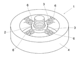
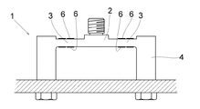
図7は従来の通常の6分力ロードセルの斜視図、図8は平面図、図9は断面図である。この形状の6分力ロードセル1は、特許文献1、その他でその構造は周知であり、一応の水準の測定精度が得られる。このロードセル1は上面の荷重受部2が十字状に配置した4本の断面四角形のスポーク柱3を介して外周の円筒体4に支持されているが、スポーク柱3を完全に支持するためには、円筒体4は十分な剛性が必要とされる。このロードセル1は全ての分力、つまり図10に示すようにX、Y、Z軸の3方向の力Fx、Fy、Fzとその軸回りの3つの偶力Mx、My、Mzの座標軸が、一点に集中しているという利点を持っていて、焦点形6分力ロードセルとも云われている。
7 is a perspective view of a conventional normal 6-component load cell, FIG. 8 is a plan view, and FIG. 9 is a cross-sectional view. The structure of the 6-
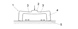
図11の模式断面図のように、台座5に固定した円筒体4の剛性が不足すると、図12に示すように引っ張り荷重により円筒体4が僅かに内側にすぼまり、又は図13に示すように圧縮荷重により外側に拡がる変形が生ずる。これにより、円筒体4と例えば台座5との間に相対的な引きずりが生じ、これがヒステリシス発生の原因となって、安定した高精度の歪検出が困難となることがある。
As shown in the schematic cross-sectional view of FIG. 11, when the rigidity of the
ロードセル1には、4本のスポーク柱3に3方向の力とその偶力検出に必要な歪ゲージ6が接着されて、通常ではフルブリッジ回路の構成が必要となる。それぞれの分力を検出する歪ゲージ6の接着位置の配置は、検出すべき1つの分力に対しては検出応力が最大限に有効な歪を捉え、それをブリッジ出力として信号を出さなければならない。他の5つの分力に対しては、なるべくは不感又は応力歪が相殺されて、歪検出の出力がないようにフルブリッジ回路を構成して、分力間の干渉を避けるように配置されている。
In the
フルブリッジ回路構成では、Fx、Fy、Mx、Myは各4素子の歪ゲージ6による構成に、Fz、Mzを測定するための各8素子を加えて、計32素子の歪ゲージ6を用いて6分力を検出することになる。4本のスポーク柱3には、それぞれ8素子の歪ゲージ6を接着し、1本のスポーク柱3の各面に、それぞれ2素子の歪ゲージ6の接着をしなければならない。長さ2mm程度の歪ゲージ6を接着するとしても、2素子の歪ゲージ6を接着するための占有面積をスポーク柱3の各面上に必要とする。
In the full-bridge circuit configuration, Fx, Fy, Mx, and My are each configured with a
一方、前述したように円筒体4の剛性を確保する必要があり、直径方向の厚み寸法を大きくする必要が生じ、図9に示すように、円筒体4の肉厚を大きくすると、円筒体4の内径が小さくなりスポーク柱3が短くなる。円筒体4の外径が25mm程度以下のロードセル1では、スポーク柱3が配置される円筒体4の内径が小さくなり過ぎて、4本のスポーク柱3に計32素子もの歪ゲージ6を接着することは困難である。
On the other hand, it is necessary to ensure the rigidity of the
最近になって、ヒューマノイドロボットの手首或いは更に小さい指等に加わる力の測定用、その他の医療用等に、外径25mm以下、特に外径18mm以下で高安定の6分力ロードセルの要望が多い。 Recently, there is a great demand for a highly stable 6-component force load cell with an outer diameter of 25 mm or less, particularly an outer diameter of 18 mm or less, for measuring the force applied to the wrist of a humanoid robot or a smaller finger, or for other medical purposes. .
現状では、これらの小径の6分力ロードセルでは、歪ゲージ6の接着面積の不足のため、ブリッジ回路構成を2素子の歪ゲージと残りの2素子を歪ゲージに相当する単純な抵抗を用いてダミー化する手法を用い、歪検出回路を所謂ハーフブリッジ回路とした構成が採用されている。しかし、このハーフブリッジ回路はフルブリッジ回路と比較して、検出出力電圧が約1/2になり、SN比の低下でノイズの増加を伴い、更に周囲の温度変化に対する温度安定度も悪化し、分力相互間の干渉特性も生じ易い。
At present, these 6-component load cells with a small diameter have a short bonding area of the
更に、直径18mm以下のロードセルでは歪ゲージの接着面積がなく、所謂1ゲージ法のブリッジ回路が用いられている。この1ゲージ法では、残りの3素子分の歪ゲージがダミー化され、出力が1/4となって、ハーフブリッジ回路よりも更に温度特性を始め、諸特性が悪化する。 Further, a load cell having a diameter of 18 mm or less does not have a strain gauge bonding area, and a so-called 1 gauge bridge circuit is used. In this one-gauge method, the strain gauges for the remaining three elements are made dummy, the output becomes 1/4, and the temperature characteristics are further deteriorated and various characteristics are deteriorated as compared with the half-bridge circuit.
このようなハーフブリッジ回路或いは1ゲージ法の歪検出回路を用いて、ロードセルを超小形化する場合には、残りのダミー抵抗はロードセル1の内部に収納できないので、別位置に固定しなければならないが、この場合に、ダミー抵抗を設置する適当な場所がないことも屡々発生する。別位置に配置した場合には、ロードセル本体とダミー抵抗間に温度差が発生し易く、零安定度等が大幅に悪化する。
When the load cell is miniaturized using such a half-bridge circuit or a strain detection circuit of the 1 gauge method, the remaining dummy resistors cannot be stored inside the
本発明の目的は、上述の課題を解消し、フルブリッジ回路の採用が可能で、分力間の干渉も少なく高精度で小型の多軸力ロードセルを提供することにある。 An object of the present invention is to solve the above-mentioned problems, to provide a high-accuracy and small-sized multiaxial force load cell that can employ a full bridge circuit, has little interference between component forces.
上記目的を達成するための本発明に係る多軸力ロードセルの技術的特徴は、荷重測定に際して弾性変形可能な厚みにした円筒形の保持体内に、断面四角形の4本のスポーク柱の外端部を接続して十字状に配置し、これらのスポーク柱を結合した内端部により荷重受部を支持すると共に、これらのスポーク柱の各側面に歪ゲージを高々1素子ずつ貼付した同形の2つのロードセル半部を、前記保持体の端縁同士を向き合わせて上下対称に配置して前記保持体の端縁同士を接続したことにある。
Technical characteristics of the multi-axis force load cell according to the present invention for achieving the above object, the holding body cylindrical and the elastic deformable thickness during load measurement, the outer end portions of the four spokes pillars of square cross section connect the arranged in a cross shape, to support the load receiving the end portion in that combines these spokes pillars of isomorphous was stuck by at most 1 device a strain gauge on each side surfaces of the
本発明に係る多軸力ロードセルによれば、円筒形の保持体内にそれぞれ4本のスポーク柱を有する2つの半部部材を組み合わせることにより、高精度化、小型化が可能となる。 According to the multiaxial load cell according to the present invention, high accuracy and miniaturization can be achieved by combining two half members each having four spoke columns in a cylindrical holding body .
本発明を図1〜図6に図示の実施例に基づいて詳細に説明する。
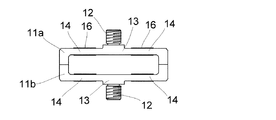
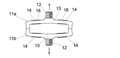
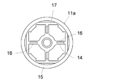
図1は実施例の斜視図、図2は平面図、図3は断面図である。この多軸力ロードセルである6分力ロードセルは、2つのロードセル半部11a、11bが上下対称に組み合わされている。それぞれのロードセル半部11a、11bにおいては、ねじ部12を有する平板状の荷重受部13が4本の十字状に配置したスポーク柱14の内端部により支持され、スポーク柱14の外端部は外周の円筒形の円筒体15に接続されている。
The present invention will be described in detail based on the embodiment shown in FIGS.
1 is a perspective view of the embodiment, FIG. 2 is a plan view, and FIG. 3 is a cross-sectional view. In this 6-component force load cell which is a multi-axis force load cell, two
各ロードセル半部11a、11bは従来の6分力ロードセルの形状と相似形であり、例えばアルミニウムなどの金属ブロックから機械加工などにより切り出して製作されている。上下のロードセル半部11a、11bは円筒体15の端縁同士を固着して一体構造とされ、一体化するに際しては、2つのロードセル半部11a、11bのスポーク柱14は各平行面を一致して配置されている。
Each of the
この構造により、2つの荷重受部13は上下に独立して設けられることになり、スポーク柱14もそれぞれ上下に4本ずつ存在し、スポーク柱14の総本数は8本となり、32素子の歪ゲージ16を接着するには、1本のスポーク柱14当たり4素子を接着することになり、断面が四角のスポーク柱14では一面に1素子の歪ゲージ16を接着すればよいことになる。
With this structure, the two
実際の製作に当たっては、各ロードセル半部11a、11bのスポーク柱14に歪ゲージ16を貼り付け、リード線を引き出してから、円筒体15同士を溶接等により固着することになる。
In actual production, the
例えば、フルブリッジ回路構成により、上方のロードセル半部11aにFx、Fy、Mx、My検出機能を持たせ、下方のロードセル半部11bにFz、Mz検出の機能を持たせると、Fz、Mzの座標軸(Z軸)はFx、Mxの座標軸(X軸)とFy、Myの座標軸(Y軸)の交点と交叉し、従来の焦点形6分力ロードセルと同じ座標が構成でき、実際の動きも同様になる。これにより、6分力ロードセルの焦点位置は上方のロードセル半部11aの焦点と見倣すことができる。
For example, if the upper load
このように、従来では小形化する場合に大きな無駄寸法となる円筒体15の厚みも極度に薄くして、荷重受部13の円板部と同等な厚み或いは円板部の厚み以下に薄くした構造とすることができる。
As described above, the thickness of the
そして、上下の荷重受部13のねじ部12に被測定体を連結して測定を行う。図4はこの6分力ロードセルに引っ張り荷重を負荷した状態の模式断面図であり、上下のロードセル半部11a、11bのスポーク柱14、荷重受部13と外周の円筒体15の変形を誇張して図示している。上下の荷重受部13間に引っ張り荷重を負荷すると、荷重受部13にそれぞれスポーク柱14が負荷の増加に伴って膨らむ方向に弾性変形する。この変形は上下それぞれ4本のスポーク柱14に殆ど等しい歪を発生させることになり、この弾性変形に連動して薄く成形された円筒体15が内側にすぼまるように弾性変形をする。
And it measures by connecting a to-be-measured body to the
図5は圧縮荷重を負荷した状態の模式断面図であり、上下のロードセル半部11a、11bは引っ張り荷重の場合と逆向きに変形し、同様に作用する。
FIG. 5 is a schematic cross-sectional view showing a state in which a compressive load is applied. The upper and lower
このように、荷重を負荷すると円筒体15が変形し、従来構造に比べて大きな弾性歪が発生するが、上下4本のスポーク柱14と円筒体15が一体に弾性変形を起こす。
As described above, when a load is applied, the
円筒体15の肉厚を薄くしたことで、スポーク柱14の長さを増加させることができ、構造上からも円筒体15が他の部分例えば台座等と相対的に引きずりを起こす摺動摩擦は全く発生しなくなり、これによって発生するヒステリシスと、それに関連していた非直線性も大きく改善される。
By reducing the thickness of the
この6分力ロードセルについては、6分力測定ではなく、5、4、3、2分力測定に使用してもよい。 This 6-component force load cell may be used for 5, 4, 3, 2 component measurement instead of 6 component measurement.
この6分力ロードセルについては、6分力測定ではなく、5、4、3、2分力測定に使用してもよい。また、上下のスポーク柱14は必ずしもその向きを一致させなくともよい。
This 6-component force load cell may be used for 5, 4, 3, 2 component measurement instead of 6 component measurement. Moreover, the direction of the upper and
なお、外径17mmのフルブリッジ回路の小形ロードセルを試作したところ、問題のない性能が得られた。 When a small load cell of a full bridge circuit having an outer diameter of 17 mm was prototyped, performance without problems was obtained.
図6は6分力ロードセルの変形例であり、上下の各スポーク柱14の外端部はフレクシャ17を介して、円筒体15に接続されている。
FIG. 6 shows a modification of the 6-component force load cell. The outer ends of the upper and lower spoke
11a、11b ロードセル半部
12 ねじ部
13 荷重受部
14 スポーク柱
15 円筒体
16 歪ゲージ
17 フレクシャ
11a, 11b Load cell
Claims (1)
Priority Applications (1)
| Application Number | Priority Date | Filing Date | Title |
|---|---|---|---|
| JP2005363040A JP4909583B2 (en) | 2005-12-16 | 2005-12-16 | Multi-axis load cell |
Applications Claiming Priority (1)
| Application Number | Priority Date | Filing Date | Title |
|---|---|---|---|
| JP2005363040A JP4909583B2 (en) | 2005-12-16 | 2005-12-16 | Multi-axis load cell |
Publications (3)
| Publication Number | Publication Date |
|---|---|
| JP2007163405A JP2007163405A (en) | 2007-06-28 |
| JP2007163405A5 JP2007163405A5 (en) | 2010-03-25 |
| JP4909583B2 true JP4909583B2 (en) | 2012-04-04 |
Family
ID=38246462
Family Applications (1)
| Application Number | Title | Priority Date | Filing Date |
|---|---|---|---|
| JP2005363040A Active JP4909583B2 (en) | 2005-12-16 | 2005-12-16 | Multi-axis load cell |
Country Status (1)
| Country | Link |
|---|---|
| JP (1) | JP4909583B2 (en) |
Families Citing this family (12)
| Publication number | Priority date | Publication date | Assignee | Title |
|---|---|---|---|---|
| JP5459890B1 (en) * | 2013-09-10 | 2014-04-02 | 株式会社ワコー | Force sensor |
| KR101574017B1 (en) | 2014-05-23 | 2015-12-02 | 명지대학교 산학협력단 | Load cell structure based on a nonlinear strain model |
| JP6354948B2 (en) | 2014-09-16 | 2018-07-11 | ティアック株式会社 | Load cell and method of manufacturing load cell |
| JP2016210561A (en) * | 2015-05-08 | 2016-12-15 | 日東電工株式会社 | Conveying method and conveying apparatus for sheet member |
| JP6694062B2 (en) * | 2016-06-08 | 2020-05-13 | 日立オートモティブシステムズ株式会社 | Force sensor |
| US10634695B2 (en) * | 2017-04-26 | 2020-04-28 | Minebea Mitsumi Inc. | Force sensor |
| JP2019066454A (en) | 2017-09-29 | 2019-04-25 | ミネベアミツミ株式会社 | Strain gauge and sensor module |
| JP6793103B2 (en) | 2017-09-29 | 2020-12-02 | ミネベアミツミ株式会社 | Strain gauge |
| JP2019184344A (en) | 2018-04-05 | 2019-10-24 | ミネベアミツミ株式会社 | Strain gauge and manufacturing method therefor |
| US11774303B2 (en) | 2018-10-23 | 2023-10-03 | Minebea Mitsumi Inc. | Accelerator, steering wheel, six-axis sensor, engine, bumper and the like |
| JP6998076B2 (en) * | 2020-03-02 | 2022-01-18 | 株式会社レプトリノ | Force sensor |
| CN116929702B (en) * | 2023-09-15 | 2023-12-29 | 中国人民解放军32806部队 | Aerodynamics test balance device and test method for aircraft |
Family Cites Families (4)
| Publication number | Priority date | Publication date | Assignee | Title |
|---|---|---|---|---|
| JPH01156632A (en) * | 1987-12-15 | 1989-06-20 | Kawasaki Steel Corp | Multi component force sensor |
| JPH036432A (en) * | 1989-06-02 | 1991-01-11 | Chinkou Higashijima | Multiple component force detector |
| JPH0676933B2 (en) * | 1989-08-22 | 1994-09-28 | 株式会社昭和測器 | Maybe force / force detector |
| JP3459939B2 (en) * | 1999-03-17 | 2003-10-27 | 関西ティー・エル・オー株式会社 | Force sensor |
-
2005
- 2005-12-16 JP JP2005363040A patent/JP4909583B2/en active Active
Also Published As
| Publication number | Publication date |
|---|---|
| JP2007163405A (en) | 2007-06-28 |
Similar Documents
| Publication | Publication Date | Title |
|---|---|---|
| JP4909583B2 (en) | Multi-axis load cell | |
| KR102080426B1 (en) | Force / torque sensor with instrumentation on less than 4 beam surfaces | |
| US7441470B2 (en) | Strain gauge type sensor and strain gauge type sensor unit using the same | |
| KR101335432B1 (en) | Force-torque sensor, force-torque sensor frame and force-torque measuring method | |
| JP2909729B2 (en) | 6-component load cell | |
| JP4192084B2 (en) | Multi-axis sensor | |
| JP4203051B2 (en) | Force sensor | |
| US20120180575A1 (en) | Capacitance-type force sensor | |
| WO2010079660A1 (en) | Force sensor | |
| KR102183179B1 (en) | Multi-axis force-torque sensor using straingauges | |
| JP4877665B2 (en) | 3-axis force sensor | |
| JP4249735B2 (en) | Force sensor | |
| JP3168179U (en) | Force sensor and six-dimensional force detection device | |
| JP5117804B2 (en) | 6-axis force sensor | |
| JP4929257B2 (en) | Force sensor | |
| JPH05149811A (en) | Axial force sensor for six components | |
| US20050120809A1 (en) | Robotic force sensing device | |
| JP5765648B1 (en) | Force sensor | |
| JP2008096230A5 (en) | ||
| JP4347165B2 (en) | Multi-axis force sensor | |
| EP3295141B1 (en) | Multi axis load cell body | |
| JP2020012660A (en) | Torque sensor | |
| JP5273023B2 (en) | Component meter | |
| JPH01262431A (en) | Force sensor | |
| Ha et al. | Elastic structure for a multi-axis forcetorque sensor |
Legal Events
| Date | Code | Title | Description |
|---|---|---|---|
| A521 | Request for written amendment filed |
Free format text: JAPANESE INTERMEDIATE CODE: A523 Effective date: 20081128 |
|
| A621 | Written request for application examination |
Free format text: JAPANESE INTERMEDIATE CODE: A621 Effective date: 20081128 |
|
| A521 | Request for written amendment filed |
Free format text: JAPANESE INTERMEDIATE CODE: A523 Effective date: 20100205 |
|
| A871 | Explanation of circumstances concerning accelerated examination |
Free format text: JAPANESE INTERMEDIATE CODE: A871 Effective date: 20100205 |
|
| A975 | Report on accelerated examination |
Free format text: JAPANESE INTERMEDIATE CODE: A971005 Effective date: 20100301 |
|
| A131 | Notification of reasons for refusal |
Free format text: JAPANESE INTERMEDIATE CODE: A131 Effective date: 20100309 |
|
| A521 | Request for written amendment filed |
Free format text: JAPANESE INTERMEDIATE CODE: A523 Effective date: 20100507 |
|
| A02 | Decision of refusal |
Free format text: JAPANESE INTERMEDIATE CODE: A02 Effective date: 20100525 |
|
| A521 | Request for written amendment filed |
Free format text: JAPANESE INTERMEDIATE CODE: A523 Effective date: 20100823 |
|
| A911 | Transfer to examiner for re-examination before appeal (zenchi) |
Free format text: JAPANESE INTERMEDIATE CODE: A911 Effective date: 20100902 |
|
| A912 | Re-examination (zenchi) completed and case transferred to appeal board |
Free format text: JAPANESE INTERMEDIATE CODE: A912 Effective date: 20101112 |
|
| A521 | Request for written amendment filed |
Free format text: JAPANESE INTERMEDIATE CODE: A523 Effective date: 20111219 |
|
| A01 | Written decision to grant a patent or to grant a registration (utility model) |
Free format text: JAPANESE INTERMEDIATE CODE: A01 |
|
| A61 | First payment of annual fees (during grant procedure) |
Free format text: JAPANESE INTERMEDIATE CODE: A61 Effective date: 20120116 |
|
| FPAY | Renewal fee payment (event date is renewal date of database) |
Free format text: PAYMENT UNTIL: 20150120 Year of fee payment: 3 |
|
| R150 | Certificate of patent or registration of utility model |
Ref document number: 4909583 Country of ref document: JP Free format text: JAPANESE INTERMEDIATE CODE: R150 Free format text: JAPANESE INTERMEDIATE CODE: R150 |
|
| R250 | Receipt of annual fees |
Free format text: JAPANESE INTERMEDIATE CODE: R250 |
|
| R250 | Receipt of annual fees |
Free format text: JAPANESE INTERMEDIATE CODE: R250 |
|
| R250 | Receipt of annual fees |
Free format text: JAPANESE INTERMEDIATE CODE: R250 |
|
| R250 | Receipt of annual fees |
Free format text: JAPANESE INTERMEDIATE CODE: R250 |
|
| R250 | Receipt of annual fees |
Free format text: JAPANESE INTERMEDIATE CODE: R250 |
|
| R250 | Receipt of annual fees |
Free format text: JAPANESE INTERMEDIATE CODE: R250 |
|
| R250 | Receipt of annual fees |
Free format text: JAPANESE INTERMEDIATE CODE: R250 |
|
| R250 | Receipt of annual fees |
Free format text: JAPANESE INTERMEDIATE CODE: R250 |
|
| R250 | Receipt of annual fees |
Free format text: JAPANESE INTERMEDIATE CODE: R250 |
|
| R250 | Receipt of annual fees |
Free format text: JAPANESE INTERMEDIATE CODE: R250 |