JP4909188B2 - X-ray CT system - Google Patents
X-ray CT system Download PDFInfo
- Publication number
- JP4909188B2 JP4909188B2 JP2007162809A JP2007162809A JP4909188B2 JP 4909188 B2 JP4909188 B2 JP 4909188B2 JP 2007162809 A JP2007162809 A JP 2007162809A JP 2007162809 A JP2007162809 A JP 2007162809A JP 4909188 B2 JP4909188 B2 JP 4909188B2
- Authority
- JP
- Japan
- Prior art keywords
- contrast
- time
- ray
- scan
- subject
- Prior art date
- Legal status (The legal status is an assumption and is not a legal conclusion. Google has not performed a legal analysis and makes no representation as to the accuracy of the status listed.)
- Expired - Fee Related
Links
- 238000012544 monitoring process Methods 0.000 claims description 44
- 238000003384 imaging method Methods 0.000 claims description 34
- 239000002872 contrast media Substances 0.000 claims description 33
- 238000011144 upstream manufacturing Methods 0.000 claims description 4
- 238000004364 calculation method Methods 0.000 claims description 2
- 238000002583 angiography Methods 0.000 claims 1
- 230000001678 irradiating effect Effects 0.000 claims 1
- 230000001131 transforming effect Effects 0.000 claims 1
- 238000003745 diagnosis Methods 0.000 description 42
- 238000000034 method Methods 0.000 description 31
- 210000004185 liver Anatomy 0.000 description 26
- 238000002347 injection Methods 0.000 description 13
- 239000007924 injection Substances 0.000 description 13
- 230000008859 change Effects 0.000 description 11
- 206010028980 Neoplasm Diseases 0.000 description 10
- 210000000702 aorta abdominal Anatomy 0.000 description 10
- 230000002440 hepatic effect Effects 0.000 description 9
- 230000002123 temporal effect Effects 0.000 description 7
- 238000013480 data collection Methods 0.000 description 6
- 238000012545 processing Methods 0.000 description 5
- 238000002083 X-ray spectrum Methods 0.000 description 4
- 238000001514 detection method Methods 0.000 description 4
- 238000010586 diagram Methods 0.000 description 4
- 230000008569 process Effects 0.000 description 4
- 230000000302 ischemic effect Effects 0.000 description 3
- 210000001015 abdomen Anatomy 0.000 description 2
- 238000010521 absorption reaction Methods 0.000 description 2
- 230000000694 effects Effects 0.000 description 2
- 238000010894 electron beam technology Methods 0.000 description 2
- 208000024200 hematopoietic and lymphoid system neoplasm Diseases 0.000 description 2
- 230000006872 improvement Effects 0.000 description 2
- 230000003902 lesion Effects 0.000 description 2
- 238000012986 modification Methods 0.000 description 2
- 230000004048 modification Effects 0.000 description 2
- 230000009467 reduction Effects 0.000 description 2
- 230000000630 rising effect Effects 0.000 description 2
- 230000000007 visual effect Effects 0.000 description 2
- 206010019695 Hepatic neoplasm Diseases 0.000 description 1
- 230000037396 body weight Effects 0.000 description 1
- 238000005094 computer simulation Methods 0.000 description 1
- 238000012790 confirmation Methods 0.000 description 1
- 238000002594 fluoroscopy Methods 0.000 description 1
- 206010073071 hepatocellular carcinoma Diseases 0.000 description 1
- 231100000844 hepatocellular carcinoma Toxicity 0.000 description 1
- 208000014018 liver neoplasm Diseases 0.000 description 1
- 230000003211 malignant effect Effects 0.000 description 1
- 210000003240 portal vein Anatomy 0.000 description 1
- 210000003462 vein Anatomy 0.000 description 1
- 238000012800 visualization Methods 0.000 description 1
- 238000004846 x-ray emission Methods 0.000 description 1
Images


Description
本発明は、X線CT装置に係り、特に造影検査を想定した場合においても診断対象を適切に識別可能なX線CT装置に関する。 The present invention relates to an X-ray CT apparatus, and more particularly to an X-ray CT apparatus capable of appropriately identifying a diagnosis target even when a contrast examination is assumed.
X線CT装置は、ファンビーム(扇形ビーム)もしくはコーンビーム(円錐形または角錐形ビーム)のX線を被検体に照射し、被検体を透過したX線の強度に基づいて被検体内部のX線吸収係数の分布情報を画像化するものであり、病変の診断において重要な役割を果たしている。 An X-ray CT apparatus irradiates a subject with X-rays of a fan beam (fan-shaped beam) or cone beam (conical or pyramidal beam), and based on the intensity of the X-ray transmitted through the subject, The distribution information of the linear absorption coefficient is imaged and plays an important role in the diagnosis of lesions.
X線CT装置において、得られた断層像内の診断対象を識別するためには、コントラスト分解能が十分に確保されている必要がある。コントラスト分解能は、画質指標の一種であるCNR(Contrast Noise Ratio)に左右される。ここで、CNRは、診断対象とその周囲とのCT値差(コントラスト)の絶対値を画像SD(画像Standard Deviation、画像ノイズ標準偏差値)で除した値として定義される。 In the X-ray CT apparatus, in order to identify the diagnosis target in the obtained tomographic image, it is necessary to ensure sufficient contrast resolution. The contrast resolution depends on CNR (Contrast Noise Ratio) which is a kind of image quality index. Here, the CNR is defined as a value obtained by dividing the absolute value of the CT value difference (contrast) between the diagnosis target and its surroundings by the image SD (image standard deviation, image noise standard deviation value).
CNRは画像SDに反比例するため、一般的には、線量を増大させて画像SDを小さくすることによって、CNRを向上させる。しかしながら、被検者の被曝という観点から、CNR向上のために単純に線量を増加させれば良いというわけでない。すなわち、実際のスキャンにおいては、診断目的に応じて適切なCNRを確保しつつ、被検者の被曝線量を可能な限り抑えることが望ましい。 Since the CNR is inversely proportional to the image SD, generally, the CNR is improved by increasing the dose and reducing the image SD. However, from the viewpoint of subject exposure, it is not always necessary to simply increase the dose in order to improve CNR. That is, in an actual scan, it is desirable to suppress the exposure dose of the subject as much as possible while ensuring an appropriate CNR according to the diagnostic purpose.
これに対応するため、特許文献1には、X線CT装置において診断対象を識別するために適切なCNRを保持しつつ個々の患者が受ける被曝線量を低減させ、それを達成しうるX線条件をスキャン開始前に予め簡便に決定する技術が記載されている。
In order to cope with this,
ところで、X線CT装置の造影検査は、病変部の良性・悪性の確定等の質的診断を行う目的で行われる。このため、診断用画像を撮影するためのスキャン(メインスキャン)は、被検体に投与した造影剤が撮影部位に流入するタイミングで行うことが重要となる。 By the way, the contrast examination of the X-ray CT apparatus is performed for the purpose of qualitative diagnosis such as benign / malignant confirmation of a lesion. For this reason, it is important to perform a scan (main scan) for capturing a diagnostic image at a timing when the contrast agent administered to the subject flows into the imaging region.
これに対応するため、特許文献2には、メインスキャンの前に撮影部位上流側での低線量スキャン(モニタリングスキャン)を行いながらある特定部位のCT値を監視しておき、CT値がある一定の閥値を超えた時点でモニタリングスキャンを中止し、自動的にメインスキャンを開始する技術が記載されている。
In order to cope with this, in
また、非特許文献1には、被検者体重や造影剤濃度、造影剤注入速度、造影剤注入時間、造影剤注入量などを予め操作者が入力しておくことで、モニタリングスキャンによって監視された特定部位のCT値の時間的変化、すなわち造影剤の立ち上がり初期形状から診断対象のCT値の時間的変化を予測する技術が記載されている。
しかしながら、診断対象と周囲組織とのコントラストは、特許文献2に記載されている通り、造影の時相によって変化する。しかしながら、特許文献1の技術では、診断対象と周囲組織とのコントラストを患者サイズ・管電圧等を考慮した上で一定の値として決定しており、造影の時相によるコントラスト変化は考慮されていない。そのため、特許文献1の技術においては、造影の時相によっては、診断のために確保されなければならないCNRが満たされない場合や、逆に過剰なCNRとなってしまう場合も考えられ、これにより適切な診断を下す上での障害や過剰被曝の原因となる可能性がある。
However, as described in
本発明は、上記事情に鑑みてなされたものであり、造影スキャンにおけるコントラストの時間的変化を考慮した場合においても、診断に適したCNRを保持して造影検査を行うX線CT装置を提供することを目的とする。 The present invention has been made in view of the above circumstances, and provides an X-ray CT apparatus that performs a contrast examination while maintaining a CNR suitable for diagnosis even when a temporal change in contrast in a contrast scan is taken into consideration. For the purpose.
前記課題を解決するために、請求項1に記載のX線CT装置は、被検体にX線を照射するX線源と、前記被検体を透過してきたX線を検出するX線検出器とを備え、前記X線源及び前記X線検出器を造影剤が注入された前記被検体の周囲で回転させるスキャンにより前記被検体の検査部位の造影撮影を行うX線CT装置において、前記被検体に造影剤を注入することにより時間的に変化する診断対象の濃度と周囲組織の濃度の差を表すコントラストであって、前記スキャン時の時相に対応するコントラストを予測する予測手段と、前記スキャン時の時相におけるX線条件を、前記予測したコントラストに基づいて予め設定されたコントラストノイズ比を満足するように算出する算出手段と、前記算出されたX線条件となるように、前記X線源を制御する制御手段と、を備えたことを特徴としている。
In order to solve the above-mentioned problem, an X-ray CT apparatus according to
請求項1に記載の画像処理装置によれば、被検体に造影剤を注入することにより時間的に変化する診断対象の濃度と周囲組織の濃度の差を表すコントラストであって、スキャン時の時相に対応するコントラスト、すなわちスキャン時のある時点におけるコントラストを予測する。予測されたコントラストに基づいて予め設定されたコントラストノイズ比(CNR)を満足するようなX線条件を算出する。算出されたX線条件となるように、X線源を制御してスキャンを行う。これにより、造影スキャンにおけるコントラストの時間的変化を考慮した場合においても、診断に適したCNRを保持することができる。
According to the image processing apparatus of
なお、請求項1に記載のX線CT装置において、診断対象の撮影部位又は該撮影部位よりも上流側の特定部位を、スキャン時よりも低線量でモニタリングスキャンを行い、これにより得られる時間濃度曲線(TDC:Time Density Curve)に基づいて、スキャン時の時相とその時相における前記コントラストとの関係を予測するようにしてもよい。これにより、より確実な撮影タイミングでメインスキャンを行うことができる。また、モニタリングスキャンを行うことにより、被検体に造影剤を注入することにより時間的に変化する診断対象の時間濃度曲線と周囲組織の時間濃度曲線との差を表す時間コントラスト曲線(TCC:Time Contrast Curve)をより確実に予測することができる。
The X-ray CT apparatus according to
本発明によれば、造影スキャンにおけるコントラストの時間的変化を考慮した場合においても、診断に適したCNRを保持して造影検査を行うことができる。 According to the present invention, a contrast examination can be performed while maintaining a CNR suitable for diagnosis even when a temporal change in contrast in a contrast scan is taken into consideration.
以下、本発明を実施するための最良の形態を添付図面に基づいて説明する。 The best mode for carrying out the present invention will be described below with reference to the accompanying drawings.
<第1の実施の形態>
図1は、本発明に係る第1の実施の形態のX線CT装置100の全体の構成を示す外観図を示し、図2は、上記X線CT装置100のブロック構成図を示す。なお、ここではX線管が1つの場合について説明しているが、本発明は多線源型のX線CT装置でも適用可能である。また、X線CT装置は、被写体全体をカバーするようなワイドファンビームを照射しつつ、X線管と検出器が一体となり回転する回転/回転(Rotate/Rotate)方式や、電子ビームを電気的に偏向させながらターゲット電極に当てていく電子ビーム走査(Scanning Electron Beam)方式など、現在までに様々な方式が確立されているが、いずれの方式においても本発明を適用可能である。ここでは、現在主流を占めている回転/回転方式に適用した場合として説明する。また、1スライスの断層像データを再構成するには、被検体1周分約360度の投影データが必要になるフルスキャン方式と180度+ビュー角分の投影データが必要になるハーフスキャン方式がある。本発明はいずれの再構成方式でも適用可能である。
<First Embodiment>
FIG. 1 is an external view showing the overall configuration of the
図1に示すように、X線CT装置100は、主として、ガントリ1と、患者テーブル2と、操作卓3と、患者テーブル2に設けられている天板4と、表示装置5と、操作装置6とで構成される。患者テーブル2上の天板4に固定された被検体7がガントリ1内に搬入されてスキャンされることにより、被検体7内部のX線吸収係数分布情報が取得される。
As shown in FIG. 1, an
ガントリ1は、図2に示すように、主として、X線管10と、高電圧発生装置11と、スリップリング12と、コリメータ13と、X線検出器14と、データ収集回路15と、架台駆動部16と、駆動フレーム17と管電圧・管電流測定装置18とで構成される。
As shown in FIG. 2, the
X線管10は、被検体7にX線を照射するものであり、X線を照射するために、高電圧発生装置11からスリップリング12を経由してX線管10に電力が供給され、それによりX線管10から断続的あるいは連続的にX線が放射される。X線管10に供給される管電圧・管電流は、管電圧・管電流測定装置18により常に測定され、その結果を反映して高電圧発生装置11は、X線管10に供給される管電圧・管電流を制御する。
The
コリメータ13は、X線管10から放射されたX線を、例えば、角錐形のX線ビームすなわちコーンビームX線として被検体7に照射させるものである。
The
X線検出器14は、X線管10から放射され、被検体7を透過したX線を検出するものである。
The
データ収集回路15は、X線検出器14に接続されており、X線検出器14の個々のX線検出素子の検出データを収集するものである。
The
駆動フレーム17には、上述のX線管10と、高電圧発生装置11と、スリップリング12と、コリメータ13と、X線検出器14と、データ収集回路15と、管電圧・管電流測定装置18とが搭載されている。駆動フレーム17は、システム制御装置20によって制御される架台駆動部16から伝達される駆動力によって回転される。
The
患者テーブル2は、図2に示すように、主として、天板4と、テーブル制御装置21と、天板駆動装置22とで構成される。
As shown in FIG. 2, the patient table 2 mainly includes a
テーブル制御装置21は、天板駆動装置22を制御して、天板4の高さの制御と、天板4の前後動の制御を行う。これにより、被検体7がガントリ1のX線照射空間に搬入及び搬出される。
The table control device 21 controls the top plate driving device 22 to control the height of the
操作卓3は、図2に示すように、主として、表示装置5と、操作装置6と、システム制御装置20と、画像再構成装置23と、記憶装置24と、スキャン計画装置25と、TDC・TCC予測装置26と、造影剤注入制御装置27とで構成される。
As shown in FIG. 2, the console 3 mainly includes a
表示装置5は、システム制御装置20に接続されており、画像再構成装置23から出力される再構成画像やシステム制御装置20が取り扱う種々の情報を表示するものである。
The
操作装置6は、システム制御装置20に接続されており、操作者によって各種の指示、情報等をシステム制御装置20に入力するものである。操作者は、表示装置5及び操作装置6を使用して、対話的にX線CT装置を操作することができる。
The
システム制御装置20は、ガントリ1と患者テーブル2とに接続されており、ガントリ1内の高電圧発生装置11、コリメータ制御装置(図示せず)、データ収集回路15、及びX線検出器14を制御し、また、患者テーブル2内のテーブル制御装置21を制御するものである。
The system controller 20 is connected to the
画像再構成装置23は、システム制御装置20の制御によってガントリ1内のデータ収集回路15で収集されたデータが入力され、スキャノグラム撮影時には、データ収集回路15が収集したスキャノグラム投影データ(被検体透視データ)を用いてスキャノグラム画像を作成し、スキャン時には、データ収集回路15が収集した複数ビューの投影データを用いてCT画像再構成を行うものである。
The
記憶装置24は、システム制御装置20に接続されており、画像再構成装置23において作成されたスキャノグラム画像・再構成されたCT画像、各種データ、及びX線CT装置の機能を実現するためのプログラム等が格納される。
The
スキャン計画装置25は、システム制御装置20に接続されており、操作装置6から入力された指示と記憶装置24から読み出されたスキャノグラム画像とを用いて、操作者がスキャン条件の事前計画を作成するものである。すなわち、記憶装置24から読み出されたスキャノグラム画像が表示装置5に表示され、操作者は表示された被検体スキャノグラム画像上で操作装置6を用いてCT画像再構成位置(以下、スライス位置という)の座標を指定することにより、スキャン時のスライス位置の設定を行うことができる。さらにここで設定されたスライス位置の情報は記憶装置24に保存され、スキャン計画装置25によってX線量制御条件等の計画を立てるためにも用いられる。予めスキャノグラム撮影を実施された被検体に対して、最適なX線量を計画する機能については、様々の公知の技術を使用することができる。
The
TDC・TCC予測装置26は、予め入力されている被検体の体格などの情報や、モニタリングスキャンによって得られた情報を基に撮影部位でのTDC及びTCCを予測するものである。さらにTDC・TCC予測装置26には、造影剤を適切に注入する造影剤注入制御装置27が接続されている。なお、TDC及びTCCについては、後で詳述する。
The TDC /
上記のように構成されたX線CT装置100は、以下のように作用する。
The
X線管10から放射されたX線は、コリメータ13によってX線照射範囲が制御され、例えば、ファンビーム(扇形ビーム)もしくはコーンビーム(円錐形または角錐形ビーム)X線とされ、被検体7に照射される。撮影者が設定したスキャン範囲は、天板駆動装置22及びテーブル制御装置21で天板4の位置を制御することで調節される。
The X-ray emission range of the X-ray emitted from the
被検体7を透過したX線はX線検出器14にによって検出される。一般的にX線検出器14はマルチスライスCT装置の場合、体軸方向に2〜数百列、体幅方向に数百〜1000チャネルのX線検出素子を配列した曲面構造を成しており、このような検出器14で電気信号に変換された検出データは、DAS(Data Acquisition System)と呼ばれるデータ収集回路15に伝送され、AD変換されてシステム制御装置20の制御によって記憶装置24に蓄積される。蓄積された収集データをもとに画像再構成装置23がCT画像の再構成を行い、表示装置5に画像として表示される。本撮影(メインスキャン)前のスキャノグラム撮影の際には、データ収集回路15が取得した被検者の投影データを用いて、画像再構成装置23においてスキャノグラム画像が再構成され、メインスキャンの際には、データ収集回路15が取得した複数ビューの投影データを用いて、画像再構成装置23において画像再構成が行われる。
X-rays transmitted through the subject 7 are detected by the
画像再構成装置23によって作成されたスキャノグラム画像や再構成されたCT画像は、記憶装置24に格納される。
The scanogram image created by the
さて、本実施の形態では、診断対象を適切に識別するために、被検体に投与した造影剤が撮影部位に流入するタイミングで診断用画像をスキャンすることが重要である。 In the present embodiment, it is important to scan the diagnostic image at the timing when the contrast agent administered to the subject flows into the imaging region in order to appropriately identify the diagnosis target.
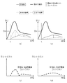
以下、肝臓の造影をした場合のTDC・TCCについて、図3を用いて説明する。図3は、造影スキャンを行った場合のTDC及びTCCを示す図であり、(a)は腹部大動脈、多血性腫瘍(診断対象)及び肝実質(周囲組織)のTDCを示し、(b)は腹部大動脈、乏血性腫瘍及び肝実質のTDCを示し、(c)は肝実質一多血性腫瘍TCC(CT値差の絶対値)を示し、(d)は肝実質一乏血性腫瘍TCCを示す。 Hereinafter, TDC / TCC when the liver is imaged will be described with reference to FIG. FIG. 3 is a diagram showing TDC and TCC when a contrast scan is performed, (a) shows TDC of abdominal aorta, bloody tumor (diagnosis target) and liver parenchyma (surrounding tissue), (b) Abdominal aorta, ischemic tumor and hepatic parenchyma TDC are shown, (c) shows hepatic parenchymal polycytic tumor TCC (absolute value of CT value), and (d) shows hepatic parenchymal ischemic tumor TCC.
TDCとは、時間による造影剤の濃度の変化を示すものであり、時間とEU(Enhancement Unit)との関数で表される。なお、EUとは、造影後のCT値から造影前のCT値を差し引いた値である。また、図中のTH(Threshold)はモニタリングスキャンにおける閾値である。 The TDC indicates a change in the concentration of the contrast agent with time, and is represented by a function of time and EU (Enhancement Unit). The EU is a value obtained by subtracting the CT value before contrast from the CT value after contrast. Further, TH (Threshold) in the figure is a threshold value in the monitoring scan.
肝臓をスキャンする場合には、通常、被検体へ径静脈的に造影剤を注入し、肝臓より上流に位置している腹部大動脈を対象としてモニタリングスキャンが行われる。モニタリングスキャンは、メインスキャンの前に行われるもので、CT値が取得可能であって、かつできるだけ低いX線量で行われる。 When scanning the liver, usually, a contrast medium is injected into a subject intravenously in a radial vein, and a monitoring scan is performed on the abdominal aorta located upstream from the liver. The monitoring scan is performed before the main scan, and the CT value can be acquired and is performed with the lowest possible X-ray dose.
モニタリングスキャンにより測定されるEUからTDCの立ち上がり初期形状を解析することで、肝臓及び所望の診断対象(各種腫瘍等)のTDCを予測することができる。また、モニタリングスキャンにより測定されるEUから、メインスキャンを開始するタイミングを計ることができる。すなわち、モニタリングスキャンにより測定されるEUが、闇値であるTHを超えた後、すなわちモニタリングスキャンを開始してから時間tが経過した後で、肝臓の造影スキャンが開始される。 By analyzing the initial rising shape of the TDC from the EU measured by the monitoring scan, it is possible to predict the TDC of the liver and a desired diagnosis target (such as various tumors). In addition, the timing for starting the main scan can be measured from the EU measured by the monitoring scan. That is, the contrast scan of the liver is started after the EU measured by the monitoring scan exceeds the dark value TH, that is, after the time t has elapsed since the monitoring scan was started.
この場合には、被検者体重や撮影部位、造影剤濃度、造影剤注入速度、造影剤注入時間、造影剤注入量などの諸条件を予め操作者が入力しておくことにより、診断対象や周囲組織のTDCを予測する。これについては、先述の非特許文献1に示すような公知技術を用いることができる。また、上記のような諸条件によって時間tも異なる値となる。
In this case, the operator inputs the conditions such as the subject's body weight, imaging region, contrast agent concentration, contrast agent injection speed, contrast agent injection time, contrast agent injection amount, etc. in advance. Predict TDC of surrounding tissue. About this, the well-known technique as shown in the above-mentioned
また、予測された診断対象のTDCと周囲組織のTDCとからTCCを算出して、スキャン条件決定に用いる。すなわち、所定の時点における診断対象と周囲組織とのコントラストの値は、所定の時点における診断対象のEUと周囲組織のEUとの差の絶対値とすることで、TCCが算出できる。 Further, the TCC is calculated from the predicted TDC of the diagnosis target and the TDC of the surrounding tissue and used for determining the scanning condition. That is, the TCC can be calculated by setting the contrast value between the diagnosis target and the surrounding tissue at a predetermined time as an absolute value of the difference between the EU of the diagnosis target and the EU of the surrounding tissue at the predetermined time.
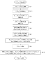
次に、本実施の形態における一連のスキャン動作を、図4を用いて説明する。 Next, a series of scan operations in the present embodiment will be described with reference to FIG.
まず、被検体7のスキャノグラム撮影が行われ(ステップSl)、ステップS1で得られたスキャノグラムを基に、操作者により診断対象を含んだスキャン領域が操作装置6を介して入力される(ステップS2)。ここで、スライス位置のスキャン条件として、スライス厚、スキャン時間、再構成フィルター関数、視野サイズ、ウインドウ条件等が入力される。また、ステップS1で得られたスキャノグラムを基に、モニタリングスキャン位置が設定される(ステップS3)。 First, scanogram imaging of the subject 7 is performed (step S1), and based on the scanogram obtained in step S1, a scan region including a diagnosis target is input by the operator via the operation device 6 (step S2). ). Here, a slice thickness, a scan time, a reconstruction filter function, a visual field size, a window condition, and the like are input as scan conditions for slice positions. Further, a monitoring scan position is set based on the scanogram obtained in step S1 (step S3).
スキャン対象とする造影の時相が操作者により操作装置6を介して入力される(ステップS4)。このステップS4における造影時相の入力においては、スキャンプロトコルにより、記憶装置24に保持してあるTDCやTCCを呼び出して、図5に示すようなTDCまたはTCCを表示装置5を介して予め操作者に示しておくと良い。ここで、スキャンプロトコルとは、X線CT装置100に設定されているスキャンの手順及び被検体の体格や撮影部位に応じた撮影条件である。この処理に用いるTDCやTCCは、標準人体ファントムを使用して取得したデータ、健常者をボランティア撮影して取得したデータ、使用者が過去に取得したデータなどのいずれであってもよい。ただし、当該被検者と同等の体格、及び身体的特徴を持ったデータを操作者が入力した被検者情報に基づいて抽出する方が好ましい。
An imaging time phase to be scanned is input by the operator via the operation device 6 (step S4). In the input of the contrast time phase in step S4, the TDC or TCC stored in the
ここで、TCCが図5のように示されている場合に、スキャン対象とする造影の時相を設定する方法について説明する。 Here, a method for setting the time phase of the contrast to be scanned when the TCC is shown as in FIG. 5 will be described.
表示装置5に表示された図5に示すようなTCCに基づいて、操作者は、例えばGUIを用いて、視覚的にスキャン対象とする造影の時相を入力する。なお、入力方式は表示されたTCC上に直接マウスポイントする方式や、プルダウンメニュー等を設けて入力する方式など、様々な入力方式を用いることができる。
Based on the TCC as shown in FIG. 5 displayed on the
図5中のA、B、Cはそれぞれ肝臓領域を複数にわたり間欠的にスキャンする場合に設定される時相の例を示したものである。Aは、予測されたTCCにおける最大コントラストの1/2(1/2C_maX)の時相Tl近辺(早期動脈相)を想定したものであり、Bはコントラストが最大(C_maX)となる時相T2近辺(後期動脈相)を想定したものであり、Cは造影開始後、時間T3だけ経過した時相近辺(平衡相)を想定したものである。また、図5におけるスキャンA、B、Cの帯状に示した領域はそれぞれの時相での大まかなスキャン時間を示す。一般的には、MDCT(マルチスライスCT)で全肝を撮影する場合、5〜10秒程度で撮影が可能である。なお、造影の時相は、1つでもよいし、複数でもよいが、本実施の形態では図5に示すような3個の時相が入力される。 A, B, and C in FIG. 5 show examples of time phases set when a plurality of liver regions are intermittently scanned. A assumes the time phase Tl (early arterial phase) of 1/2 (1 / 2C_maX) of the maximum contrast in the predicted TCC, and B indicates the time phase T2 where the contrast is maximum (C_maX). (Late arterial phase) is assumed, and C is assumed to be in the vicinity of the time phase (equilibrium phase) after the time T3 has elapsed since the start of imaging. In addition, the areas shown in the band shapes of the scans A, B, and C in FIG. 5 indicate rough scan times in the respective time phases. Generally, when the whole liver is imaged by MDCT (multi-slice CT), imaging can be performed in about 5 to 10 seconds. The contrast time phase may be one or plural, but in this embodiment, three time phases as shown in FIG. 5 are input.
なお、表示装置5に表示されるものは、TCCのみでなく、操作者が見慣れた肝腫瘍(診断対象)もしくは肝実質(周囲組織)のTDCを表示させるようにしても良い。これ以外の表示方法であっても、表示されるTDCやTCCは趣旨を逸脱しない範囲においてどのように変形しても良い。
The
撮影時相の入力後、診断対象を識別可能なCNR(CNR_d)が、記憶装置24から呼び出される(ステップS5)。そして、CNR_dを満たすような最適なスキャン条件が、入力された造影時相毎に予備的に算出される(ステップS6)。ここでの最適なスキャン条件とは、被検者の被曝を最小にしつつ、CNR_dを満たす管電圧及び管電流である。本実施例では、管電圧は造影時相に依らずスキャン中一定であるが、管電流は被検者の体軸方向及びX線管の回転方向にアダプティブに変化させるものとする。ステップS6で設定された最適なスキャン条件及び付随的な情報として、画像SDや被曝線量等を表示装置5に表示させることで操作者に示すようにしても良い。
After inputting the imaging time phase, the CNR (CNR_d) that can identify the diagnosis target is called from the storage device 24 (step S5). Then, an optimal scan condition that satisfies CNR_d is preliminarily calculated for each inputted contrast time phase (step S6). The optimum scanning conditions here are a tube voltage and a tube current that satisfy CNR_d while minimizing the exposure of the subject. In this embodiment, the tube voltage is constant during scanning regardless of the contrast time phase, but the tube current is adaptively changed in the body axis direction of the subject and the rotation direction of the X-ray tube. As the optimum scanning condition set in step S6 and accompanying information, the image SD, the exposure dose, and the like may be displayed on the
なお、本実施の形態では、ステップS5において診断対象を識別可能なCNR_dを記憶装置24の中から呼び出す例を挙げて説明しているが、CNR_dはシステム制御装置20が備える演算機能を用いて、本願発明者等が先に出願した特許文献1に記載された方法(特許文献1のステップS304乃至ステップS310)によって算出することもできる。これは、後述の第2の実施の形態及び第3の実施の形態についても同様である。
In the present embodiment, an example in which CNR_d that can identify a diagnosis target is called from the
予備的なスキャン条件が算出されたら、そのスキャン条件で設定されたモニタリングスキャン位置に対してモニタリングスキャンが行われ、TDC・TCC予測装置26によって、腹部大動脈、多血性腫瘍(診断対象)及び肝実質(周囲組織)のTDC及びTCCが予測されると共に、モニタリングスキャンで予測されたTCCを基に、実際のスキャンを行う際に用いられる最適なスキャン条件が算出される(ステップS7)。ステップS4で入力された造影の時相を設定するためのTDC、TCCは、ステップS7で予測されるTCCに反映される。これにより、造影で想定される診断対象と周囲組織とのコントラストがそれぞれの時相毎に予測される。
When the preliminary scan conditions are calculated, a monitoring scan is performed on the monitoring scan position set under the scan conditions, and the TDC /
ここで、予測されるTCCは、標準管電圧(例えば120kV)時のものであるが、本ステップで算出された最適管電圧の情報を取り込み、図6に示すように、X線スペクトルを考慮することで、TCCの形状を適宜変化させるようにした方が良い。ここで、図6は、腹部大動脈TDC及び肝実質TCCの補正形状を示したものであり、(a)は被検者の身長及び体重が一定で造影剤注入レートを変化させた場合のTDC及びTCCであり、(b)はスキャン管電圧を変えることによるX線スペクトルが変化した場合の肝実質のTCCである。このように、被検者情報やX線スペクトルを考慮することによってTCCの精度が向上し、撮影線量が制御され所望の画質を得られることが期待される。また、X線CT装置100の体軸方向へのスキャン速度によっては、ステップS7で算出されたTCCの通りにならない場合も考えられる。従って、特開2006−296493に記載されているような、スキャン範囲の全域にわたって、操作者所望のコントラストとなるような造影時相近辺をスキャンする技術を用いるようにしてもよい。
Here, the predicted TCC is at the time of a standard tube voltage (for example, 120 kV), but the information of the optimum tube voltage calculated in this step is taken in and the X-ray spectrum is taken into consideration as shown in FIG. Therefore, it is better to change the shape of the TCC as appropriate. Here, FIG. 6 shows the corrected shape of the abdominal aorta TDC and liver parenchyma TCC, and (a) shows the TDC when the height and weight of the subject are constant and the contrast agent injection rate is changed. (B) is the TCC of the liver parenchyma when the X-ray spectrum is changed by changing the scan tube voltage. Thus, it is expected that the TCC accuracy is improved by taking into account the subject information and the X-ray spectrum, and the imaging dose is controlled to obtain a desired image quality. Further, depending on the scanning speed of the
そして、モニタリングスキャンにより測定されるEUが、闇値であるTHを超えた後、すなわちモニタリングスキャンを開始してから時間tが経過した後で、予め設定されたスキャン領域のスキャン(メインスキャン)が開始され(ステップS8)、ステップS7で予測されたTCCを基に、入力された各造影時相における診断対象と周囲組織とのコントラストに応じてCNR_dを満たすようなスキャン条件でスキャンが行われる(ステップS9)。例えば、図5で示したように肝臓の3つの時相を操作者が設定していた場合には、A、B、Cそれぞれの時相でのコントラストに応じた画像SDになるように、撮影条件が制御される。具体的には、CNRはコントラストを画像SDで除した値として定義されるため、A及びBのそれぞれの時相において満たすべき画像SDは、操作者が設定した時相T1においては1/2C_max/CNR_dとして求められ、時相T2においてはC_max/CNR_dとして求められる。これを満たすように管電流を制御すれば良い。実際には、スキャン速度とスキャン時間経過にともなうコントラスト変化を考慮したCNRとなるように、スキャン条件を制御すればよい。これにより、より適切な撮影条件で撮影を行うことができる。 Then, after the EU measured by the monitoring scan exceeds the dark value TH, that is, after the time t has elapsed since the monitoring scan was started, a scan (main scan) of a preset scan area is performed. Based on the TCC predicted in step S7, scanning is performed under a scanning condition that satisfies CNR_d according to the contrast between the diagnosis target and the surrounding tissue in each inputted contrast time phase (step S8) (step S8). Step S9). For example, when the operator has set three time phases of the liver as shown in FIG. 5, the image is taken so as to obtain an image SD corresponding to the contrast in each time phase of A, B, and C. Conditions are controlled. Specifically, since the CNR is defined as a value obtained by dividing the contrast by the image SD, the image SD to be satisfied in each time phase of A and B is 1 / 2C_max / in the time phase T1 set by the operator. It is obtained as CNR_d, and is obtained as C_max / CNR_d in the time phase T2. The tube current may be controlled to satisfy this. Actually, the scan conditions may be controlled so that the CNR takes into account the change in contrast with the scan speed and the scan time. Thereby, it is possible to perform photographing under more appropriate photographing conditions.
図7は、ボリュームスキャンの場合の撮影プロトコルの例である。図7(a)は肝臓を造影スキャンする場合であり、図中(i)、(ii)、(iii)はそれぞれ図5のA、B、Cの時相に対応している。この場合、モニタリングスキャン位置は、肝臓の下部、腹部大動脈付近に設定されており、望ましくは矢印のような体軸方向へスキャンする方式が良い。また、図7(b)は、胸腹部を非造影スキャンし、肝臓は造影スキャンする場合であり、図中(i)は単純撮影であり、(ii)、(iii)、(iv)は、それぞれ図5のA、B、Cの時相に対応した造影撮影である。この場合には、検査時間や被検者に与える負担を考慮して、胸腹部を非造影スキャン(単純撮影)してモニタリングスキャン位置に到達した後でモニタリングスキャンを開始し、TDC・TCCの予測後に造影剤を注入して造影スキャンを開始する方が適当である。このように操作者は任意の領域をスキャンすることができ、モニタリングスキャンの場所も手技によって適当な場所に設定することができる。図7(b)のよう単純撮影をすることで、診断の性能を向上させることができる。 FIG. 7 is an example of an imaging protocol in the case of volume scanning. FIG. 7A shows a case where a contrast scan of the liver is performed, and (i), (ii), and (iii) in the figure correspond to the time phases of A, B, and C in FIG. In this case, the monitoring scan position is set at the lower part of the liver and in the vicinity of the abdominal aorta, and a method of scanning in the body axis direction as indicated by an arrow is preferable. FIG. 7B shows a case where the chest and abdomen are subjected to a non-contrast scan and the liver is subjected to a contrast scan. In FIG. 7B, (i) is a simple image, and (ii), (iii), and (iv) are The contrast imaging corresponds to the time phases A, B, and C in FIG. In this case, considering the examination time and the burden on the subject, the monitoring scan is started after the non-contrast scan (simple imaging) of the chest and abdomen and the monitoring scan position is reached, and prediction of TDC / TCC It is more appropriate to start a contrast scan by injecting a contrast agent later. In this way, the operator can scan an arbitrary area, and the location of the monitoring scan can be set to an appropriate location by a technique. By performing simple imaging as shown in FIG. 7B, diagnostic performance can be improved.
本実施の形態によれば、造影スキャンにおけるコントラストの時間的変化を考慮した場合においても、診断に適したCNRを保持して、かつCNRを達成しうる画像SDを保ちながら、被検体の被曝線量を最小にすることができる。 According to the present embodiment, even when a temporal change in contrast in a contrast scan is considered, the exposure dose of the subject is maintained while maintaining a CNR suitable for diagnosis and maintaining an image SD that can achieve the CNR. Can be minimized.
また、本実施の形態によれば、画像SDのみでなく、診断に有効なコントラストが考慮されたCNRを用いてスキャン線量の制御を行うため、より診断に適切な画像を得ることができる。 Further, according to the present embodiment, since the scan dose is controlled using not only the image SD but also the CNR in consideration of the contrast effective for diagnosis, an image more suitable for diagnosis can be obtained.
また、本実施の形態によれば、操作者が注目しない時相ではスキャンを行わないため、被検体の被曝線量を低減することが可能になる。 Further, according to the present embodiment, since the scan is not performed in a time phase where the operator does not pay attention, it is possible to reduce the exposure dose of the subject.
また、本実施の形態によれば、モニタリングスキャンを行うことにより、EUが、闇値であるTHを超える時間が測定されるため、より確実にTCCを予測し、より確実な撮影タイミングでメインスキャンを行うことができる。 Further, according to the present embodiment, since the time when the EU exceeds the dark value TH is measured by performing the monitoring scan, the TCC is predicted more reliably, and the main scan is performed at a more reliable shooting timing. It can be performed.
なお、本実施の形態では、モニタリングスキャンを実施することが前提となっていたが、モニタリングスキャンを省略することも可能である。この場合には、被検者情報やプロトコルが入力された時点で、これらを用いて予めTDCやTCCを予測しておけば良い。これにより、モニタリングスキャンの必要がないので、さらなる被曝低減効果が見込める。 In the present embodiment, it is assumed that the monitoring scan is performed, but the monitoring scan can be omitted. In this case, TDC and TCC may be predicted in advance using the information on the subject when the subject information and protocol are input. As a result, there is no need for a monitoring scan, so a further effect of reducing exposure can be expected.
また、本実施の形態では、管電圧は造影時相に依らずスキャン中一定であるとしたが、それぞれの時相で管電圧を変化させても良い。それぞれの時相において管電圧を変化させることで、操作者の所望のコントラストでスキャンすることが可能となる。 In the present embodiment, the tube voltage is constant during scanning regardless of the contrast time phase. However, the tube voltage may be changed at each time phase. By changing the tube voltage in each time phase, it is possible to scan with the contrast desired by the operator.
また、本実施の形態に記載のTCCに応じた管電流等のスキャン条件の制御に、ビューによる線量制御を追加して行なってもよい。これにより、より適切な制御を行うことができる。 Further, the dose control by the view may be added to the control of the scanning condition such as the tube current according to the TCC described in the present embodiment. Thereby, more appropriate control can be performed.
また、本実施の形態では、操作者が入力できる造影の時相は複数であったが、もちろん1つのみ入力することも可能である。この場合には、1ボリュームスキャンで撮影が終了するので、大幅な被曝低減効果が期待できる。 Further, in this embodiment, there are a plurality of contrast time phases that can be input by the operator, but it is of course possible to input only one. In this case, since the photographing is completed in one volume scan, a significant exposure reduction effect can be expected.
なお、肝細胞癌の識別、描出、診断においては、単純撮影を含めて3〜4相のフェーズでの撮影が一般的である。実際の臨床現場では、造影剤注入開始後40秒前後の肝動脈相(hepatic arterial phase)、80秒前後の門脈相(portal venous phase)、120秒前後の平衡相(equilibrium phase)が広く撮影に用いられている。ここでT1、T2、T3の設定は、操作者がマウスによって選択する方式等を示したが、これらの3〜4相を予めプロトコルとして保持しておき、操作者の入力なしに撮影タイミングを決定する方式も考えられる。これにより操作者の作業効率が高まり、より簡便に撮影を行うことが可能になる。この時、造影剤注入速度や被検者の体格等を考慮することで、撮影タイミングを適宜補正するようにした方が望ましい。 Note that in the identification, visualization, and diagnosis of hepatocellular carcinoma, imaging is generally performed in three to four phases including simple imaging. In actual clinical settings, hepatic arterial phase around 40 seconds after the start of contrast agent injection, portal vein phase around 80 seconds, and equilibrium phase around 120 seconds are widely taken. It is used for. Here, the setting of T1, T2, and T3 indicates a method in which the operator selects with the mouse. However, these three to four phases are stored in advance as a protocol, and the photographing timing is determined without input by the operator. A method to do this is also possible. This increases the work efficiency of the operator and enables easier shooting. At this time, it is desirable to appropriately correct the imaging timing in consideration of the contrast agent injection speed, the physique of the subject, and the like.
<第2の実施の形態>
第1の実施の形態は、肝臓を造影スキャンする場合において、各撮影時相で肝臓をボリュームスキャンする場合であるが、造影スキャンの実施形態はこれに限るものではない。
<Second Embodiment>
The first embodiment is a case of performing a volume scan of the liver at each imaging time phase when performing a contrast scan of the liver, but the embodiment of the contrast scan is not limited to this.
第2の実施の形態は、肝臓を造影スキャンする場合において、各撮影時相で肝臓をダイナミックスキャンするものである。以下の説明において、第1の実施の形態と同一の部分については、同一の符号を付し、説明を省略する。 In the second embodiment, when the liver is contrast-scanned, the liver is dynamically scanned at each imaging time phase. In the following description, the same parts as those in the first embodiment are denoted by the same reference numerals, and description thereof is omitted.
図8は、第2の実施形態における処理の流れを示すフローチャートである。 FIG. 8 is a flowchart showing the flow of processing in the second embodiment.
スキャノグラム撮影の終了後(ステップS1)、得られたスキャノグラムを基に、操作者により診断対象を含んだスキャン位置が入力装置5を介して入力される(ステップS11)。本実施の形態では、スキャンは同一スライス位置でスキャンを行うダイナミックスキャンを意味する。それと同時に、スライス位置のスキャン条件として、スライス厚、スキャン時間、再構成フィルター関数、視野サイズ、ウインドウ条件等が入力される。
After the scanogram imaging is completed (step S1), the scan position including the diagnosis target is input by the operator via the
スキャン位置の入力後、モニタリングスキャンの位置が設定され(ステップS3)、その後、スキャン対象とする造影の時相が操作者により操作装置6を介して入力される(ステップS4)。 After inputting the scan position, the position of the monitoring scan is set (step S3), and then the contrast time phase to be scanned is input by the operator via the operation device 6 (step S4).
撮影時相の入力後、診断対象を識別可能なCNR(CNR_d)が、記憶装置24に格納してあるプロトコルから呼び出される(ステップS5)。そして、CNR_dを満たすような画像SDに対応する最適なスキャン条件が、入力された造影時相毎に予備的に算出される(ステップS6)。 After inputting the imaging time phase, the CNR (CNR_d) that can identify the diagnosis target is called from the protocol stored in the storage device 24 (step S5). Then, an optimal scan condition corresponding to the image SD satisfying CNR_d is preliminarily calculated for each inputted contrast time phase (step S6).
次いで上記予備的なスキャン条件で、設定されたモニタリングスキャン位置でモニタリングスキャンが行われ、TDC・TCC予測装置26によって、腹部大動脈、多血性腫瘍(診断対象)及び肝実質(周囲組織)のTDC及びTCCが予測されると共に、モニタリングスキャンで予測されたTCCを基に、実際のスキャンを行う際に用いられる最適なスキャン条件が算出される(ステップS7)。
Next, a monitoring scan is performed at the set monitoring scan position under the above-described preliminary scanning conditions, and the TDC and
そして、モニタリングスキャンにより測定されるEUが、闇値であるTHを超えた後、すなわちモニタリングスキャンを開始してから時間tが経過した後で、予め設定されたスキャン位置のスキャンが開始され(ステップS8)、前記ステップT7で予測したTCCを基に、操作者が入力した造影時相における診断対象と周囲組織とのコントラストに応じてCNR_dを満たすようなスキャン条件でステップT2において設定したスキャン位置のダイナミックスキャンが行われる(ステップS12)。 Then, after the EU measured by the monitoring scan exceeds the dark value TH, that is, after the time t has elapsed since the monitoring scan was started, scanning at a preset scan position is started (step S8) Based on the TCC predicted in step T7, the scan position set in step T2 under the scan condition satisfying CNR_d according to the contrast between the diagnosis target and the surrounding tissue in the contrast time phase input by the operator A dynamic scan is performed (step S12).
この場合、操作者が設定した造影時相の場合のみ、CNR_dを満たす画像SDになるようにスキャン条件が制御される。例えば、図5を用いて説明すると、画像SDが満たすべき条件として、時相T1においては1/2C_max/CNR_dとなり、時相T2においてはC_max/CNR_dとなるようにスキャンする。また、設定時相が3つの場合は3回スキャンが行われることを意味する。 In this case, only in the contrast time phase set by the operator, the scanning conditions are controlled so that the image SD satisfies CNR_d. For example, referring to FIG. 5, as a condition to be satisfied by the image SD, scanning is performed so as to be 1 / 2C_max / CNR_d in the time phase T1 and C_max / CNR_d in the time phase T2. Further, when there are three set time phases, it means that the scan is performed three times.
本実施の形態によれば、造影スキャンにおけるコントラストの時間的変化を考慮した場合においても、診断に適したCNRを保持し、かつCNRを達成しうる画像SDを保ちながら、被検体の被曝線量を最小にすることができる。 According to the present embodiment, even when a temporal change in contrast in a contrast scan is taken into consideration, the exposure dose of the subject is maintained while maintaining a CNR suitable for diagnosis and maintaining an image SD that can achieve the CNR. Can be minimized.
また、本実施の形態によれば、操作者が設定した時相においては、常時所望のCNRを満たすことができるため、特定の時相に着目した場合の診断能の向上が期待できる。すなわち、診断対象のあるスライスにおいて、注目すべき時相での最適なCNRが達成できる。コントラストが大きい時相に注目して撮影する場合には、より被曝を低減させることができる。 Further, according to the present embodiment, since the desired CNR can always be satisfied in the time phase set by the operator, an improvement in diagnostic ability when focusing on a specific time phase can be expected. That is, in a slice to be diagnosed, an optimal CNR at a notable time phase can be achieved. Exposure can be further reduced when shooting with attention to a time phase having a high contrast.
なお、本実施の形態では、モニタリングスキャンを実施することが前提となっていたが、第1の実施の形態と同様に、モニタリングスキャンを省略することも可能である。 In the present embodiment, it is assumed that a monitoring scan is performed. However, as in the first embodiment, the monitoring scan can be omitted.
本実施の形態の変形例としては、全時相におけるダイナミックスキャンが考えられる。この場合には、予測されるTCCの形状に応じて順次CNR_dを満たすよう画像SDを制御することにより、同一スライス位置における全時相の診断画像を得ることが可能となる。 As a modification of the present embodiment, dynamic scanning in all time phases can be considered. In this case, it is possible to obtain diagnostic images of all time phases at the same slice position by sequentially controlling the image SD so as to satisfy CNR_d according to the predicted shape of the TCC.
<第3の実施の形態>
第1の実施の形態は、肝臓を造影スキャンする場合において、各撮影時相で肝臓をボリュームスキャンする場合であるが、造影スキャンの実施形態はこれに限るものではない。
<Third Embodiment>
The first embodiment is a case of performing a volume scan of the liver at each imaging time phase when performing a contrast scan of the liver, but the embodiment of the contrast scan is not limited to this.
第3の実施の形態は、肝臓を造影スキャンする場合において、予測されるコントラストが所定の値以上である場合のみ撮影を行うものである。以下の説明において、第1の実施の形態と同一の部分については、同一の符号を付し、説明を省略する。 In the third embodiment, imaging is performed only when the predicted contrast is equal to or higher than a predetermined value in the contrast scan of the liver. In the following description, the same parts as those in the first embodiment are denoted by the same reference numerals, and description thereof is omitted.
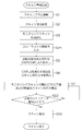
図9は、第3の実施形態における処理の流れを示すフローチャートである。
まず、被検体7のスキャノグラム撮影が行われ(ステップSl)、ステップS1で得られたスキャノグラムを基に、操作者により診断対象を含んだスキャン領域が操作装置6を介して入力される(ステップS2)。ここで、スライス位置のスキャン条件として、スライス厚、スキャン時間、再構成フィルター関数、視野サイズ、ウインドウ条件等を入力する。また、ステップS1で得られたスキャノグラムを基に、モニタリングスキャン位置が設定される(ステップS3)。
FIG. 9 is a flowchart showing the flow of processing in the third embodiment.
First, scanogram imaging of the subject 7 is performed (step S1), and based on the scanogram obtained in step S1, a scan region including a diagnosis target is input by the operator via the operation device 6 (step S2). ). Here, a slice thickness, a scan time, a reconstruction filter function, a visual field size, a window condition, and the like are input as scan conditions for slice positions. Further, a monitoring scan position is set based on the scanogram obtained in step S1 (step S3).
モニタリングスキャン位置が設定されたら、操作者により、スキャン対象とする造影の時相における閾値が入力装置6を介して入力される(ステップS21)。具体的には、図10に示すように、コントラストの最大値の1/2の値である1/2C_maxが閾値として入力される。この場合には、スキャンされるのは、コントラストが閾値を超えている時相(斜線Aで囲まれた時相)のみとなる。ステップS21では、スキャンプロトコルによって、表示装置5を介して、予めTCCを操作者に示しておいた方が望ましい。この処理は、記憶装置24に保持してあるTCCを呼び出せば良い。表示されるTCC、および操作者が入力する造影の時相は第1の実施形態に準じたもので良い。
When the monitoring scan position is set, the operator inputs a threshold value in the time phase of the contrast to be scanned through the input device 6 (step S21). Specifically, as shown in FIG. 10, ½C_max, which is a half value of the maximum contrast value, is input as a threshold value. In this case, only the time phase in which the contrast exceeds the threshold value (the time phase surrounded by the oblique line A) is scanned. In step S21, it is desirable that the TCC is previously shown to the operator via the
閾値が入力されたら、診断対象を識別可能なCNR(CNR_d)が、記憶装置24に格納してあるプロトコルから呼び出される(ステップS5)。そして、CNR_dを満たすような最適なスキャン条件が、入力された造影時相毎に予備的に算出される(ステップS6)。次いで予備的なスキャン条件で、設定されたモニタリングスキャン位置でモニタリングスキャンが行われ、TDC・TCC予測装置26によって、腹部大動脈、多血性腫瘍(診断対象)及び肝実質(周囲組織)のTDC及びTCCが予測されると共に、モニタリングスキャンで予測されたTCCを基に、実際のスキャンを行う際に用いられる最適なスキャン条件が算出される(ステップS7)。
When the threshold value is input, a CNR (CNR_d) that can identify the diagnosis target is called from the protocol stored in the storage device 24 (step S5). Then, an optimal scan condition that satisfies CNR_d is preliminarily calculated for each inputted contrast time phase (step S6). Next, a monitoring scan is performed at the set monitoring scan position under a preliminary scan condition, and the TDC /
スキャン条件が算出されたら、ステップS7で予測されたTCCを基に、現在の時相のコントラストがステップS21で入力された閾値を超えているかどうかが判断される(ステップS22)。 When the scan condition is calculated, it is determined whether the current time phase contrast exceeds the threshold value input in step S21 based on the TCC predicted in step S7 (step S22).
コントラストがステップS21で入力された閾値を超えていない場合(ステップS22でNO)には、ステップS7へ戻り、想定される時相までスキャンを見合わせる。
コントラストがステップS21で入力された閾値を超えている場合(ステップS22でYES)には、スキャンが実行される(ステップS23)。すなわち、ステップS7で予測されたTCCを基に、コントラストが閥値以上の造影時相のみ、診断対象と周囲組織とのコントラストに応じたCNRを満たすようなスキャン条件でスキャン領域のスキャンが行われる。なお、本実施の形態では、ボリュームスキャンを想定しているが、ダイナミックスキャンであっても適用可能である。
If the contrast does not exceed the threshold value input in step S21 (NO in step S22), the process returns to step S7, and the scan is postponed until the expected time phase.
If the contrast exceeds the threshold value input in step S21 (YES in step S22), scanning is executed (step S23). That is, based on the TCC predicted in step S7, the scan area is scanned under a scan condition that satisfies the CNR corresponding to the contrast between the diagnosis target and the surrounding tissue only in the contrast time phase in which the contrast is greater than or equal to the threshold value. . In this embodiment, volume scanning is assumed, but dynamic scanning can also be applied.
本実施の形態によれば、造影検査を行う場合であっても、操作者が所望するコントラスト以上となる時相のみでスキャンを行うため、診断能の向上、及び被曝低減が期待できる。また、所望するコントラストより低い(低コントラスト)の時相でスキャンを行わないことにより、被曝低減が期待できる。 According to the present embodiment, even when a contrast examination is performed, since the scan is performed only at a time phase that is equal to or higher than the contrast desired by the operator, an improvement in diagnostic ability and a reduction in exposure can be expected. Further, exposure is reduced by not performing scanning at a time phase lower than the desired contrast (low contrast).
なお、本実施の形態では、コントラストが所定の閾値以上となった場合のみスキャンを行ったが、操作者が図10の斜線Bで示すような所望の造影時相(Tl〜T2)となる領域を設定することも可能である。 In this embodiment, scanning is performed only when the contrast is equal to or higher than a predetermined threshold. However, the region where the operator has a desired contrast phase (Tl to T2) as indicated by the hatched line B in FIG. Can also be set.
また、本実施の形態では、モニタリングスキャンを実施することが前提となっていたが、第1の実施の形態及び第2の実施の形態と同様に、モニタリングスキャンを省略することも可能である。 Further, in the present embodiment, it is assumed that a monitoring scan is performed, but it is also possible to omit the monitoring scan as in the first and second embodiments.
以上、3つの実施例を基に本発明を説明してきたが、本発明の技術的範囲は、前述した実施の形態に限られるものではない。当業者であれば、本願で開示した技術的思想の範境内において、各種の変更例または修正例に想到し得ることは明らかであり、それらについても当然に本発明の技術的範囲に属するものと了解される。 Although the present invention has been described based on the three examples, the technical scope of the present invention is not limited to the above-described embodiments. It will be apparent to those skilled in the art that various changes and modifications can be made within the scope of the technical idea disclosed in the present application, and these naturally belong to the technical scope of the present invention. Understood.
1:ガントリ、2:患者テーブル、3:操作卓、4:天板、5:表示装置、6:操作装置、10:X線管、11:高電圧発生装置、12:スリップリング、13コリメータ:、14:X線検出器、15:データ収集回路、16:架台駆動部、17:駆動フレーム、18:管電圧・管電流測定装置、20:システム制御装置、21:テーブル制御装置、22:天板駆動装置、23:画像再構成装置、24:記憶装置、25:スキャン計画装置、26:TDC・TCC予測装置、27:造影剤注入制御装置 1: gantry, 2: patient table, 3: console, 4: top panel, 5: display device, 6: operation device, 10: X-ray tube, 11: high voltage generator, 12: slip ring, 13 collimator: , 14: X-ray detector, 15: data acquisition circuit, 16: gantry drive unit, 17: drive frame, 18: tube voltage / tube current measuring device, 20: system control device, 21: table control device, 22: sky Plate drive device 23: Image reconstruction device 24: Storage device 25: Scan planning device 26: TDC / TCC prediction device 27: Contrast medium injection control device
Claims (5)
前記被検体に造影剤を注入することにより時間的に変化する前記検査部位の濃度と周囲組織の濃度の差を表すコントラストであって、前記スキャン時の時相に対応するコントラストを予測する予測手段と、
前記スキャン時の時相におけるX線条件を、前記予測したコントラストに基づいて予め設定されたコントラストノイズ比を満足するように算出する算出手段と、
前記算出されたX線条件となるように、前記X線源を制御する制御手段と、
を備えたことを特徴とするX線CT装置。 An X-ray source for irradiating the subject with X-rays and an X-ray detector for detecting X-rays transmitted through the subject, and a contrast agent is injected into the X-ray source and the X-ray detector In the X-ray CT apparatus for performing contrast imaging of the examination site of the subject by a scan rotated around the subject,
Prediction means for predicting contrast corresponding to a time phase at the time of scanning, which is a contrast representing a difference between the density of the examination site and the density of surrounding tissue, which changes with time by injecting a contrast medium into the subject. When,
Calculation means for calculating an X-ray condition in a time phase at the time of scanning so as to satisfy a contrast noise ratio set in advance based on the predicted contrast;
Control means for controlling the X-ray source so as to satisfy the calculated X-ray condition;
An X-ray CT apparatus comprising:
前記予測手段は、前記被検体に造影剤を注入した後に前記モニタリングスキャンで得られる時間濃度曲線に基づいて、前記被検体の検査部位における前記スキャン時の時相とその時相における前記コントラストとの関係を予測することを特徴とする請求項1に記載のX線CT装置。 Means for monitoring and scanning the examination site or a specific site upstream of the examination site at a lower dose than during the scan,
The prediction means is based on a time density curve obtained by the monitoring scan after injecting a contrast medium into the subject , and a relationship between the time phase at the time of the scan at the examination site of the subject and the contrast at the time phase. The X-ray CT apparatus according to claim 1, wherein:
前記X線CT装置は、前記算出された時間コントラスト曲線を表示し、その表示された時間コントラスト曲線に基づいて、前記スキャンを行う時相を入力する入力手段を更に備える、 The X-ray CT apparatus further includes an input unit that displays the calculated time contrast curve and inputs a time phase for performing the scan based on the displayed time contrast curve.
ことを特徴とする請求項1、2、又は3に記載のX線CT装置。 The X-ray CT apparatus according to claim 1, 2, or 3.
ことを特徴とする請求項1、2、3、又は4に記載のX線CT装置。 The X-ray CT apparatus according to claim 1, 2, 3, or 4.
Priority Applications (1)
| Application Number | Priority Date | Filing Date | Title |
|---|---|---|---|
| JP2007162809A JP4909188B2 (en) | 2007-06-20 | 2007-06-20 | X-ray CT system |
Applications Claiming Priority (1)
| Application Number | Priority Date | Filing Date | Title |
|---|---|---|---|
| JP2007162809A JP4909188B2 (en) | 2007-06-20 | 2007-06-20 | X-ray CT system |
Publications (3)
| Publication Number | Publication Date |
|---|---|
| JP2009000225A JP2009000225A (en) | 2009-01-08 |
| JP2009000225A5 JP2009000225A5 (en) | 2010-07-22 |
| JP4909188B2 true JP4909188B2 (en) | 2012-04-04 |
Family
ID=40317290
Family Applications (1)
| Application Number | Title | Priority Date | Filing Date |
|---|---|---|---|
| JP2007162809A Expired - Fee Related JP4909188B2 (en) | 2007-06-20 | 2007-06-20 | X-ray CT system |
Country Status (1)
| Country | Link |
|---|---|
| JP (1) | JP4909188B2 (en) |
Families Citing this family (9)
| Publication number | Priority date | Publication date | Assignee | Title |
|---|---|---|---|---|
| JP5657658B2 (en) * | 2009-07-17 | 2015-01-21 | ピー.ローラー デイヴィッド | Enhanced low-contrast detection capability for radiographic imaging systems |
| JP2012147934A (en) * | 2011-01-19 | 2012-08-09 | Toshiba Corp | X-ray diagnostic device, image processing device and image processing program |
| JP2013005896A (en) * | 2011-06-23 | 2013-01-10 | Ge Medical Systems Global Technology Co Llc | X-ray ct device |
| JP6083990B2 (en) * | 2012-09-24 | 2017-02-22 | キヤノン株式会社 | Radiation imaging apparatus, control method thereof, and program |
| JP6605195B2 (en) | 2013-08-30 | 2019-11-13 | キヤノンメディカルシステムズ株式会社 | X-ray computed tomography equipment |
| JP6900144B2 (en) | 2014-05-08 | 2021-07-07 | 信示 芦田 | X-ray diagnostic equipment |
| KR20160042572A (en) | 2014-10-10 | 2016-04-20 | 삼성전자주식회사 | A radiographic imaging apparatus, a method of controlling the radiographic imaging apparatus and a computed tomography |
| JP2017074123A (en) * | 2015-10-13 | 2017-04-20 | 東芝メディカルシステムズ株式会社 | Medical image processing device and x-ray diagnostic device |
| JP7098338B2 (en) * | 2017-01-25 | 2022-07-11 | キヤノンメディカルシステムズ株式会社 | X-ray CT device and imaging management device |
Family Cites Families (3)
| Publication number | Priority date | Publication date | Assignee | Title |
|---|---|---|---|---|
| US6337992B1 (en) * | 1997-01-29 | 2002-01-08 | Philips Medical Systems Technologies Ltd. | Predictive bolus tracking |
| JP4528781B2 (en) * | 2003-10-29 | 2010-08-18 | コーニンクレッカ フィリップス エレクトロニクス エヌ ヴィ | Apparatus and method for adjusting imaging parameters of X-ray apparatus |
| EP1960965A2 (en) * | 2005-12-09 | 2008-08-27 | Koninklijke Philips Electronics N.V. | Model-based flow analysis and visualization |
-
2007
- 2007-06-20 JP JP2007162809A patent/JP4909188B2/en not_active Expired - Fee Related
Also Published As
| Publication number | Publication date |
|---|---|
| JP2009000225A (en) | 2009-01-08 |
Similar Documents
| Publication | Publication Date | Title |
|---|---|---|
| JP4909188B2 (en) | X-ray CT system | |
| US7145982B2 (en) | X-ray CT apparatus and method of calculating blood-flow information | |
| JP5192372B2 (en) | X-ray CT system | |
| JP5191787B2 (en) | X-ray CT system | |
| US10163209B2 (en) | Medical image processing apparatus, medical image processing method, and X-ray CT apparatus | |
| US8351565B2 (en) | X-ray CT apparatus | |
| JP4170305B2 (en) | Radiography equipment | |
| JP2007144172A (en) | Method and system for carrying out ct image reconstruction with motion artifact correction | |
| Catalano et al. | Optimizing radiation dose and image quality | |
| JP2002233525A (en) | Consulting method for organism using image forming method | |
| WO2015022888A1 (en) | Radio-tomography device | |
| JP2007144139A (en) | X-ray computed tomography apparatus and image processor | |
| JP2013169392A (en) | X-ray ct apparatus and image display method | |
| JP6466057B2 (en) | Medical diagnostic imaging equipment | |
| JP2003299643A (en) | Tomographic equipment | |
| JP2001178713A (en) | X-ray ct system, operation console, control method therefor and storage medium | |
| JP2004261224A (en) | X-ray ct apparatus | |
| JP2009005922A (en) | X-ray ct apparatus | |
| JP6873831B2 (en) | Medical image diagnostic equipment, medical image processing equipment and medical image processing program | |
| JP2013046774A (en) | X-ray tomograph | |
| JP4305720B2 (en) | X-ray CT system | |
| JP6490912B2 (en) | X-ray CT system | |
| EP3908186B1 (en) | Adaptive helical computed tomography | |
| JP2019004920A (en) | X-ray CT apparatus and X-ray irradiation condition setting method | |
| JP5220580B2 (en) | X-ray CT system |
Legal Events
| Date | Code | Title | Description |
|---|---|---|---|
| RD02 | Notification of acceptance of power of attorney |
Free format text: JAPANESE INTERMEDIATE CODE: A7422 Effective date: 20090721 |
|
| RD04 | Notification of resignation of power of attorney |
Free format text: JAPANESE INTERMEDIATE CODE: A7424 Effective date: 20090727 |
|
| A521 | Request for written amendment filed |
Free format text: JAPANESE INTERMEDIATE CODE: A523 Effective date: 20100603 |
|
| A621 | Written request for application examination |
Free format text: JAPANESE INTERMEDIATE CODE: A621 Effective date: 20100603 |
|
| TRDD | Decision of grant or rejection written | ||
| A01 | Written decision to grant a patent or to grant a registration (utility model) |
Free format text: JAPANESE INTERMEDIATE CODE: A01 Effective date: 20111227 |
|
| A977 | Report on retrieval |
Free format text: JAPANESE INTERMEDIATE CODE: A971007 Effective date: 20111228 |
|
| A01 | Written decision to grant a patent or to grant a registration (utility model) |
Free format text: JAPANESE INTERMEDIATE CODE: A01 |
|
| A61 | First payment of annual fees (during grant procedure) |
Free format text: JAPANESE INTERMEDIATE CODE: A61 Effective date: 20120113 |
|
| FPAY | Renewal fee payment (event date is renewal date of database) |
Free format text: PAYMENT UNTIL: 20150120 Year of fee payment: 3 |
|
| R150 | Certificate of patent or registration of utility model |
Free format text: JAPANESE INTERMEDIATE CODE: R150 |
|
| S111 | Request for change of ownership or part of ownership |
Free format text: JAPANESE INTERMEDIATE CODE: R313111 |
|
| S533 | Written request for registration of change of name |
Free format text: JAPANESE INTERMEDIATE CODE: R313533 |
|
| R350 | Written notification of registration of transfer |
Free format text: JAPANESE INTERMEDIATE CODE: R350 |
|
| LAPS | Cancellation because of no payment of annual fees |