JP4901954B2 - Strand guide device - Google Patents
Strand guide device Download PDFInfo
- Publication number
- JP4901954B2 JP4901954B2 JP2009505730A JP2009505730A JP4901954B2 JP 4901954 B2 JP4901954 B2 JP 4901954B2 JP 2009505730 A JP2009505730 A JP 2009505730A JP 2009505730 A JP2009505730 A JP 2009505730A JP 4901954 B2 JP4901954 B2 JP 4901954B2
- Authority
- JP
- Japan
- Prior art keywords
- channel
- strand
- strands
- curved
- guide device
- Prior art date
- Legal status (The legal status is an assumption and is not a legal conclusion. Google has not performed a legal analysis and makes no representation as to the accuracy of the status listed.)
- Active
Links
- 230000002093 peripheral effect Effects 0.000 claims description 13
- 238000003780 insertion Methods 0.000 claims description 2
- 230000037431 insertion Effects 0.000 claims description 2
- 230000000694 effects Effects 0.000 description 3
- 239000000463 material Substances 0.000 description 3
- 239000011248 coating agent Substances 0.000 description 2
- 238000000576 coating method Methods 0.000 description 2
- 238000009434 installation Methods 0.000 description 2
- 239000002184 metal Substances 0.000 description 2
- 229910052751 metal Inorganic materials 0.000 description 2
- 239000007769 metal material Substances 0.000 description 2
- 238000005096 rolling process Methods 0.000 description 2
- 238000004804 winding Methods 0.000 description 2
- 239000004593 Epoxy Substances 0.000 description 1
- 239000004698 Polyethylene Substances 0.000 description 1
- HCHKCACWOHOZIP-UHFFFAOYSA-N Zinc Chemical compound [Zn] HCHKCACWOHOZIP-UHFFFAOYSA-N 0.000 description 1
- 230000002146 bilateral effect Effects 0.000 description 1
- 230000000295 complement effect Effects 0.000 description 1
- 238000010276 construction Methods 0.000 description 1
- 238000006073 displacement reaction Methods 0.000 description 1
- 238000000034 method Methods 0.000 description 1
- 238000000465 moulding Methods 0.000 description 1
- -1 polyethylene Polymers 0.000 description 1
- 229920000573 polyethylene Polymers 0.000 description 1
- 230000000717 retained effect Effects 0.000 description 1
- 238000000926 separation method Methods 0.000 description 1
- 239000007787 solid Substances 0.000 description 1
- 229910052725 zinc Inorganic materials 0.000 description 1
- 239000011701 zinc Substances 0.000 description 1
Images


Classifications
-
- F—MECHANICAL ENGINEERING; LIGHTING; HEATING; WEAPONS; BLASTING
- F16—ENGINEERING ELEMENTS AND UNITS; GENERAL MEASURES FOR PRODUCING AND MAINTAINING EFFECTIVE FUNCTIONING OF MACHINES OR INSTALLATIONS; THERMAL INSULATION IN GENERAL
- F16G—BELTS, CABLES, OR ROPES, PREDOMINANTLY USED FOR DRIVING PURPOSES; CHAINS; FITTINGS PREDOMINANTLY USED THEREFOR
- F16G13/00—Chains
- F16G13/12—Hauling- or hoisting-chains so called ornamental chains
- F16G13/16—Hauling- or hoisting-chains so called ornamental chains with arrangements for holding electric cables, hoses, or the like
-
- E—FIXED CONSTRUCTIONS
- E01—CONSTRUCTION OF ROADS, RAILWAYS, OR BRIDGES
- E01D—CONSTRUCTION OF BRIDGES, ELEVATED ROADWAYS OR VIADUCTS; ASSEMBLY OF BRIDGES
- E01D19/00—Structural or constructional details of bridges
- E01D19/14—Towers; Anchors ; Connection of cables to bridge parts; Saddle supports
-
- F—MECHANICAL ENGINEERING; LIGHTING; HEATING; WEAPONS; BLASTING
- F16—ENGINEERING ELEMENTS AND UNITS; GENERAL MEASURES FOR PRODUCING AND MAINTAINING EFFECTIVE FUNCTIONING OF MACHINES OR INSTALLATIONS; THERMAL INSULATION IN GENERAL
- F16G—BELTS, CABLES, OR ROPES, PREDOMINANTLY USED FOR DRIVING PURPOSES; CHAINS; FITTINGS PREDOMINANTLY USED THEREFOR
- F16G11/00—Means for fastening cables or ropes to one another or to other objects; Caps or sleeves for fixing on cables or ropes
- F16G11/02—Means for fastening cables or ropes to one another or to other objects; Caps or sleeves for fixing on cables or ropes with parts deformable to grip the cable or cables; Fastening means which engage a sleeve or the like fixed on the cable
Landscapes
- Engineering & Computer Science (AREA)
- General Engineering & Computer Science (AREA)
- Architecture (AREA)
- Civil Engineering (AREA)
- Structural Engineering (AREA)
- Mechanical Engineering (AREA)
- Ropes Or Cables (AREA)
- Media Introduction/Drainage Providing Device (AREA)
- Reinforcement Elements For Buildings (AREA)
- Bridges Or Land Bridges (AREA)
Description
この発明は、ストランドの案内装置に関する。 The present invention relates to a strand guiding apparatus.
この発明は、さらに、ストランドの前記案内装置から成る構造に関する。 The invention further relates to a structure comprising the guide device for strands.
この発明は、特に、しかし専らではなく、むしろ土木工学や建築活動に使用され、複数のストランドから形成されたケーブルのストランドの案内装置の達成に関する。 The invention relates in particular, but not exclusively, to the achievement of a guide device for cable strands, which are used in civil engineering and construction activities and formed from a plurality of strands.
事実、野外における無数の構造や顕著な橋は、これら構造の要素を支持し、要素をこれら構造間に保持するように使用されるケーブルから成る。 In fact, the myriad structures and prominent bridges in the field consist of cables used to support and hold the elements between them.
そのようなケーブルがそれら対向端の間の牽引において応力されていて、しかし頻繁に案内装置がケーブルが延びなければならない方向にどんな方法でケーブルを離れないような形式にケーブルを横方向に且つ局部的に保持するために使用される。 Such cables are stressed in the traction between their opposite ends, but often the guides laterally and locally in such a way that the guide device does not leave the cable in any direction in which the cable must extend. Used to hold on.
上記引用されたタイプの案内装置の機能は、ケーブルの横方向且つ局部的保持やこの目的のために設けられた支持体に対してこの分離により生じた応力の移送を可能とする。 The function of the guide device of the type cited above allows the lateral and local holding of the cable and the transfer of the stresses resulting from this separation to the support provided for this purpose.
前記タイプの案内装置は、支持体とケーブルの間に装入されるように企図されている。 Said type of guiding device is intended to be inserted between the support and the cable.
従来には、そのような案内装置は、ケーブルの各ストランドの個々の横方向且つ局部的支持できるように想像される。
この目的のために、案内装置は、ケーブルのストランドを案内する少なくとも一つの軸受領域と、好ましくは偏向用の複数の軸受領域とから成り、各軸受領域がケーブルのストランドの一つの個々の支持を可能とする。 For this purpose, the guide device comprises at least one bearing area for guiding the cable strands and preferably a plurality of deflection bearing areas, each bearing area providing one individual support for the cable strand. Make it possible.
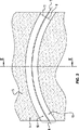
案内装置は、一般に固体である本体から形成され、少なくとも一つの彎曲したチャンネルがストランドにより横断されるように企図されたチャンネルとしてされて形成されている。 The guide device is formed from a body which is generally solid and is formed as a channel intended to have at least one curved channel traversed by the strand.
本体は従来にはストランドから成る案内ケーブルと同様に多数のチャンネルから成る。 The body conventionally consists of a number of channels as well as a guide cable made of strands.
従来には、ストランドはそれぞれに一般に金属である複数のワイアから形成されるけれども、これに限定されていない。 Conventionally, the strand is formed from a plurality of wires, each typically a metal, but is not limited thereto.
ストランドはしばしば円に記載される横断面を有するが、しかしこの断面は楕円或いは他の形状でもよい。 Strands often have a cross-section described in a circle, but this cross-section may be oval or other shapes.
チャンネルの各々はストランドが受けなければならないストランドの横断面と実質的に補足的形状の横断面を有する。 Each of the channels has a cross-section of the strand that the strand must receive and a cross-section of a substantially complementary shape.
例えばケーブルのストランドが円を記載する横断面を有するときに、各チャンネルはストランドの横断面が記載される円より大きい直径の実質的に円形の横断面を有する。 For example, when a cable strand has a cross-section describing a circle, each channel has a substantially circular cross-section with a diameter larger than the circle in which the strand cross-section is described.
本体の各チャンネルが彎曲された縦軸線と少なくとも一つの第一部分とから成り、この第一部分が縦軸線の内部の側面に原理的に位置して、チャンネルの長さの制限内に、前記ストランドの周面の一部にストランドの支持を可能することが心に留められ得る。 Each channel of the body consists of a curved longitudinal axis and at least one first part, the first part being located in principle on the inner side of the longitudinal line, and within the channel length limitation, It can be borne in mind that it is possible to support the strands on a part of the peripheral surface.
同様に、各チャンネルが少なくとも一つの第二部分から成り、この第二部分が縦軸線の外部の側面に原理的に位置して、第一部分に接続されていて、チャンネルに係合中に、前記チャンネルの縦軸線を含有する曲率平面でチャンネルを形成するためにストランドを案内できることが心に留められ得る。 Similarly, each channel consists of at least one second part, which is in principle located on the outer side of the longitudinal axis and is connected to the first part and during engagement with the channel It can be borne in mind that the strands can be guided to form the channel in a curvature plane containing the longitudinal axis of the channel.
チャンネルの縦寸法に沿って延びる軸線が縦軸線によって選定されて、チャンネル軸線がこのチャンネルの曲率平面でチャンネルの横断寸法に関して中間位置に傾斜していない。 An axis extending along the longitudinal dimension of the channel is selected by the longitudinal axis, and the channel axis is not inclined to an intermediate position with respect to the transverse dimension of the channel in the curvature plane of this channel.
指示された縦軸線が内部と外部の定義を可能とする機能として、この縦軸線により形成された曲線の内側に位置した第一地域である内部と前記縦軸線により形成された曲線の外側に位置した第二地域である外部とを有する。 The designated vertical axis is a function that enables the definition of the inside and the outside, and is located inside the first area located inside the curve formed by the vertical axis and outside the curve formed by the vertical axis And the outside which is the second area.
従来には、各チャンネルが円形横断面である。 Conventionally, each channel has a circular cross section.
例示を参照すると、装置の本体がコンクリートの塊から形成されて、各チャンネルが前記コンクリート塊に埋め込まれた彎曲されたチューブの通過によって形成される。 Referring to the illustration, the body of the device is formed from a concrete mass and each channel is formed by the passage of a curved tube embedded in the concrete mass.
ケースがどんなものであっても、このタイプの装置がそれらの利点を有し、しかし、これら案内装置を横断するストランドが据え付け後に案内装置を軸方向に移動させ得て、案内装置が荷重の下にあるときに、案内装置の片面或いは他の面から張力の変量を受けることは極めて非常に遺憾である。 Whatever the case, this type of device has their advantages, but the strands traversing these guide devices can move the guide device axially after installation so that the guide device is under load. It is very regrettable to receive a variable amount of tension from one or the other side of the guide device.
この発明が目的とする成果は、ストランドがより良く保持され、この事実と大きな範囲によって案内装置を軸方向に移動させる応力に僅かにしか感応しない前記タイプの案内装置を得ることである。 The aim of the invention is to obtain a guide device of the above-mentioned type in which the strands are better retained and, due to this fact and a large extent, are only slightly sensitive to the stresses that cause the guide device to move in the axial direction.
この目的のために、この発明の目的は請求項1による案内装置を有する。
For this purpose, the object of the invention comprises a guide device according to
この発明は同様にストランド用の前記案内装置から成る構造に関する。 The invention likewise relates to a structure comprising the guide device for strands.
この発明は、概略的に表示する添付図面を参照して、非制限例によって与えられ、次の記載を読み取ることからより良く理解される。 The invention will be better understood from a reading of the following description, given by way of non-limiting example, with reference to the accompanying drawings which are schematically represented.
図面を参照すると、ストランド2用の案内装置1を見る。
Referring to the drawing, the
例えばこの発明は複数のストランド2から形成されたケーブルのストランド2用の案内装置1に関する。
For example, the invention relates to a
従来には、ストランド2が各複数のワイア4、特に金属から形成されている。
Conventionally, the
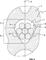
例えばストランド2が七本のワイア4のグループから成る。
For example,
表示されたストランド2が円に記載される横断面を有するが、しかしストランドが楕円或いは他の形状にも記載され得る。
The displayed
図面、図4と5に表示されるのはストランド2であり、外被或いはケーシング無しのストランドと呼ばれたタイプのストランドとして表現されるが、しかしこれはこの発明の特徴を制限しない。 Shown in the drawings, FIGS. 4 and 5 is Strand 2, which is represented as a type of strand called a strand without a jacket or casing, but this does not limit the features of the invention.
被覆されていないストランドが図6に表示されている。 Uncoated strands are displayed in FIG.
対称的に、被覆されたストランドがストランド2であり、ストランドを構成するワイア4がその長さの少なくとも一つの部分にあり、外被或いはケーシング40に収容され且つ包囲され、この外被或いはケーシング40がポリエチレン材料から形成された管状壁41のような少なくとも一つの管状壁41(図7)によって形成される。
Symmetrically, the coated strand is the
同様に、被覆されたストランドがストランド2であり、ストランドを構成するワイア4がその長さの少なくとも一つの部分にあり、外被或いはケーシング40に収容され且つ包囲され、この外被或いはケーシングが管状壁41と同様な少なくとも一つの壁により、被覆(図8)、圧延或いは巻付け(示されていない形式)或いは任意の他の方法によって形成された壁により、形成される。
Similarly, the coated strand is
例えば圧延或いは巻付けにより形成された壁を採用すると、非金属材料の層、例えばエポキシのような重合体材料或いは金属材料の層、例えば亜鉛から成ることが述べられている。 For example, the use of walls formed by rolling or winding is said to consist of a layer of non-metallic material, for example a polymeric material such as epoxy or a layer of metallic material, for example zinc.
ケースがどんなものであろうとも、この発明の装置が被覆されるストランド2と、被覆されていないストランド2と共に使用され得る。
Whatever the case, the device of the present invention can be used with the coated
案内装置1は少なくとも一つの彎曲されたチャンネル6が形成されている本体5から成り、この本体が前記チャンネル6の曲率により彎曲された縦軸線7から成り、縦軸線7の内部の側面に原理的に位置した少なくとも一つの第一部分8から成り、チャンネル6の長さの限度内に、前記ストランド2の周面の少なくとも一部分にてストランド2の支持を可能とする。
The
縦軸線7により選定されるのは、チャンネル6の縦寸法に沿って延びる軸線であり、しかし軸線がこのチャンネル6の曲線平面においてチャンネル6の横断寸法に関して中間位置に傾斜していない。 Selected by the longitudinal axis 7 is an axis extending along the longitudinal dimension of the channel 6, but the axis is not inclined to an intermediate position in the curve plane of this channel 6 with respect to the transverse dimension of the channel 6.
明記される如く、指示された縦軸線7が内部と外部の定義を可能とする機能として、この縦軸線7により形成された曲線の内側に位置した第一地域である内部と前記縦軸線7により形成された曲線の外側に位置した第二地域である外部とを有する。 As indicated, the designated vertical axis 7 functions as a function enabling definition of the inside and the outside, and the inside and the vertical line 7 are the first area located inside the curve formed by the vertical line 7. And an exterior which is a second region located outside the formed curve.
好ましくは、案内装置1は少なくとも一つの彎曲されたチャンネル6が形成されて少なくとも一つの第二部分11を備える本体5から成り、この第二部分が縦軸線7の外部の側面に原理的に位置して、第一部分8に接続されていて、チャンネル6への係合中に、特にチャンネル6の縦軸線7を含有する曲線平面12にチャンネル6を形成するためにストランド2を案内できる。
Preferably, the
ストランド2の周面10がそのストランドを構成するワイア4の周面の部分、或いは可能にこれらワイア4をカバーする被覆40の周面の部分により形成されることが考慮できるちがいない。
It must be considered that the
図4−8において、ストランドの周面10の形状は前記ストランド2の横断面をカバーする精密マーク付けによって象徴化されている。
In FIG. 4-8, the shape of the
注目すべき方法では、第一部分8が第一面13として参照して横方向接触の少なくとも二つ面により限定される第一横断面を有する。
第一面13はチャンネル6に係合されるストランド2の一部と局部的に協働できるような方法に位置され、曲線平面12の両側面に位置される周面10の二つの横地域14におけるこのストランドは、ストランドが応力を受けるときに、ストランド2の締付けの現象を開始するように少なくとも十分に予め決められた角度Aをそれらストランドの間に形成するような方法で配向されている。
In a noteworthy manner, the
The
案内装置1はストランドの支持体を形成するように構成されていて、支持体が両横方向支持体として限定することが可能である。
The
それ故に、両横方向支持体がストランド2の締付けの現象を開始するために、状況と制限された範囲のために選択される。
Therefore, both lateral supports are selected for the situation and the limited range in order to initiate the phenomenon of tightening of the
この横方向支持体を介して、締付けの現象は台形として参照されたベルトの滑車の分野において検索されたものと実質的に等しく検索される。 Through this lateral support, the phenomenon of tightening is retrieved substantially equal to that found in the field of belt pulleys referred to as trapezoids.
第一面13の間のストランドの係合が前記ストランド2の横断締付けを誘導する(示されていない)対向作用を発生させる。
The engagement of the strands between the
締付けの現象はストランド2が外被40から成る、或いは外被40から成らないときに発生される。
The tightening phenomenon occurs when the
ストランド2が外被40から成るときに、第一面13がストランド2に対して外被40を局部的に適用し、さらに、締付けの作用を発生させ、この締付けの作用(示されていない)が対向される傾向であり、外被40内で前記ストランド2のワイア4の摺動及び/ 又はチャンネル6内のストランド2の摺動が対向されている。
When the
そのように示されていて、案内装置1はパイロンの頂点(示されていない)のような支持体9に接続されている。
As shown, the
二つの第一面13が曲率平面12の両側面に位置されている。
Two
二つの第一面13が曲率平面12に関して対称的に配置されている。
Two
当業者は二つの第一面13が形成する角度の値を決定でき、これは少なくとも連続して試行する。
The person skilled in the art can determine the value of the angle formed by the two
当業者は二つの第一面13が形成する角度の値を決定でき、これはこれら第一面13の一方或いは他方とストランド2の周面10の間の摩擦係数の函数として算出される。
A person skilled in the art can determine the value of the angle formed by the two
有益には、第一面13がそれぞれに実質的に平らである。
Beneficially, the
第一面13がスムーズであるか、或いは起伏を有し得る。
The
チャンネル6の第一部分8には、第一面13が第二面16により接続されていて、この第二面はストランド2が第一面13に横方向支持体であるときに、ストランド2との任意の接触から遮断されるように形成配置されている。
A
例えば第二面16は曲率平面12に実質的に垂直に延びる横断母線を有する。
For example, the
好ましい実施例では、第二面16は、横断面で見たらこの第二面16が実質的に凹状に見られるような形式に彎曲される横断母線を有する。
In a preferred embodiment, the
如何なる場合でも、前記第二面16は、ストランド2が第一面13に横方向支持体であるときに、ストランド2との任意の接触から遮断されるように配置されている。
In any case, the
案内装置1は、ストランド2の実質的に挿入前にチャンネル6に装入されるように且つ前記ストランド2の適当な場所に設置後に前記チャンネル6から抽出されるように企図され、第二面16に支持体を設置されるように構成される少なくとも一つの可動要素17から成り、可動要素が前記第二面16に支持体を設置されるときに、二つの第一面13にストランド2の同時押圧を阻止する楔を形成する。
The
このチャンネルを通して、チャンネル内のストランド2の縦変位が締付け或いは締付けの開始無しに得られ得る。
Through this channel, the longitudinal displacement of the
可動要素17の引き出しは、ストランド2が二つの第一面13に支持体をもたらされ、このストランド2の締付けを少なくとも開始させる。
The withdrawal of the movable element 17 causes the
第二部分11に関して、第二部分は、チャンネル6内に係合中に、ストランド2の周面10の摺動をもたらすために配向された彎曲線により形成された第三面18により形成されている。
With respect to the
好ましくは顕著な形式で、第二部分11は実質的に半円形の第二横断面を有する。
Preferably in a prominent manner, the
顕著な形式では、第三面18と第二面16が少なくとも十分な形式に間隔を置いているので、可動要素17が第二面16に静止して位置されるときに、可動要素が係合なしにその機能を保証でき、チャンネル6内のストランド2の摺動が第三面18との接触により干渉されている。
In a prominent manner, the
当業者は発明活動を実演すること無しに割合を調整できる。 One skilled in the art can adjust the proportions without demonstrating the inventive activity.
当業者は、同様に、案内装置1のチャンネルを達成させるように異なった形式で且つコンクリートのような材料塊に埋め込まれる形成された横断面に一致する横断面を有するチューブを使用する有益な形式で計画できる。
The person skilled in the art likewise has the advantage of using tubes having a different cross-section corresponding to the formed cross-section embedded in a mass of material such as concrete in order to achieve the channel of the
同様に、案内装置のチャンネルが成形によって創作され得る。 Similarly, the channel of the guiding device can be created by molding.
この発明は、同様に、ここに記載された案内装置から成る構造に関する。 The invention likewise relates to a structure comprising the guide device described herein.
1.....案内装置
2.....ストランド
4.....ワイア
5.....本体
6.....チャンネル
7.....縦軸線
8.....第一部分
10....周面
11....第二部分
12....曲率平面
13....第一面
14....横地域
16....第二面
17....可動要素
18....第三面
40....外被
1. . . . .
Claims (11)
チャンネル(6)の長さの制限内に前記ストランド(2)の周面(10)の少なくとも一部分にストランド(2)を支持するのを可能とし、縦軸線(7)のチャンネル内部の側面に位置されている少なくとも一つの第一部分(8)とから成り、
この装置は、第一部分(8)が第一面(13)として参照された横方向支持体の少なくとも二つの面によって限定されている第一横断面を有し、第一面(13)がチャンネル(6)に係合されるストランド(2)の一部と局所に協働でき、曲率をもつ面(12)の両側に位置されるストランド周面(10)の二つの横地域(14)を形成するように位置されていて、この第一面はストランドが応力を受けるときにストランド(2)の締付け現象を開始するのに少なくとも十分に決定された角度(A)を第一面の間に形成するように配向されていることを特徴とする装置。In the guide device (1) for the strand (2), the guide device (1) comprises a main body (5), in which at least one curved channel (6) is formed and has a curvature. Including the longitudinal axis (7) formed in (12) , curved by the curvature of the channel (6),
And possible to support the strand (2) to at least a portion of the channel circumference of the strands in length (6) restriction (2) (10), the channel interior side of the longitudinal axis (7) Consisting of at least one first part (8) located ,
This device has a first cross section in which a first part (8) is defined by at least two faces of a transverse support referred to as a first face (13), the first face (13) being a channel. strands are engaged with (6) (2) comes to a portion locally in cooperation with the strands circumferential surface being located on opposite sides of the surface (12) having a curvature (10) two lateral regions (14) have been positioned to form, between the strands least well determined angle to initiate tightening phenomenon of (2) (a) when the first surface is the strand is subjected to stress of the first surface An apparatus characterized by being oriented to form a.
Applications Claiming Priority (1)
| Application Number | Priority Date | Filing Date | Title |
|---|---|---|---|
| PCT/EP2006/061709 WO2007121782A1 (en) | 2006-04-20 | 2006-04-20 | Strand guide device |
Publications (2)
| Publication Number | Publication Date |
|---|---|
| JP2009534555A JP2009534555A (en) | 2009-09-24 |
| JP4901954B2 true JP4901954B2 (en) | 2012-03-21 |
Family
ID=37602968
Family Applications (1)
| Application Number | Title | Priority Date | Filing Date |
|---|---|---|---|
| JP2009505730A Active JP4901954B2 (en) | 2006-04-20 | 2006-04-20 | Strand guide device |
Country Status (10)
| Country | Link |
|---|---|
| US (1) | US7900306B2 (en) |
| EP (1) | EP2007947B1 (en) |
| JP (1) | JP4901954B2 (en) |
| KR (1) | KR101255568B1 (en) |
| CN (1) | CN101421463B (en) |
| AU (1) | AU2006342459B2 (en) |
| ES (1) | ES2492568T3 (en) |
| HK (1) | HK1131416A1 (en) |
| PL (1) | PL2007947T3 (en) |
| WO (1) | WO2007121782A1 (en) |
Families Citing this family (12)
| Publication number | Priority date | Publication date | Assignee | Title |
|---|---|---|---|---|
| PL2550401T3 (en) * | 2010-03-26 | 2017-08-31 | Vsl International Ag | Bridge saddle and method for protecting strands from corrosion in such bridge saddle |
| FR2968681B1 (en) * | 2010-12-08 | 2015-05-29 | Soletanche Freyssinet | DEVICE FOR THE DEVIATION OF A STRUCTURED CABLE, SUCH AS A HAUBAN, AND A WORK THUS EQUIPPED |
| RU2569114C2 (en) * | 2011-08-12 | 2015-11-20 | Фсл Интернациональ Аг | Tensile element supply device |
| ES2533630T3 (en) * | 2012-09-03 | 2015-04-13 | Soletanche Freyssinet | Traction system using a multi-tendon cable with a deflection angle |
| CN102912727A (en) * | 2012-11-02 | 2013-02-06 | 江阴法尔胜住电新材料有限公司 | Partial extradosed bridge wire distributing pipe cable saddle capable of avoiding slipping of stranded wires of inclined stay cable |
| CN102966040B (en) * | 2012-11-21 | 2016-02-17 | 安徽佳路机械制造有限公司 | A kind of cable-stayed bridge saddle and manufacture method thereof |
| CN103015319B (en) * | 2013-01-07 | 2015-06-17 | 合肥斯派索材料科技有限公司 | Raindrop-shaped stainless steel wire distribution pipe for stay cable steering device of cable-stayed bridge tower |
| CN103266565A (en) * | 2013-05-31 | 2013-08-28 | 中交二航局第四工程有限公司安徽分公司 | Plug pin type steel strand stopping device |
| CN105445181A (en) * | 2015-11-25 | 2016-03-30 | 安徽金星预应力工程技术有限公司 | Method for measuring friction coefficients of pre-stressed ducts of water-drop-shaped cable saddle of stay cable |
| DE102016225416A1 (en) * | 2016-12-19 | 2018-06-21 | Dywidag-Systems International Gmbh | Method for installing a clamping element in an anchor block, holder, in particular for carrying out the method and combination of a holder with a clamping element |
| WO2022111811A1 (en) | 2020-11-27 | 2022-06-02 | Dywidag-Systems International Gmbh | Guiding device and combination of a guiding device with at least one strand |
| US20230159744A1 (en) * | 2021-11-24 | 2023-05-25 | Felix Sorkin | Polymer blend cradle for cable-stayed bridge |
Citations (3)
| Publication number | Priority date | Publication date | Assignee | Title |
|---|---|---|---|---|
| GB1227489A (en) * | 1968-10-23 | 1971-04-07 | ||
| JP2000054562A (en) * | 1998-08-04 | 2000-02-22 | Dyckerhoff & Widmann Ag | Direction change seat for tightening member in construction body |
| DE19928445A1 (en) * | 1999-06-23 | 2000-12-28 | Suspa Spannbeton Gmbh | Guide unit for tensioning elements comprises a cover pipe with tensioning wire strands which is surrounded by glide pipe, and a glide medium is introduced into the space between the cover and glide pipes |
Family Cites Families (12)
| Publication number | Priority date | Publication date | Assignee | Title |
|---|---|---|---|---|
| GB1277489A (en) | 1969-11-08 | 1972-06-14 | Carves Simon Ltd | Improvements in or relating to prestressed structures |
| FR2511721A1 (en) * | 1981-08-21 | 1983-02-25 | Freyssinet Int Stup | CURVED CONNECTION DEVICE BETWEEN TWO RECTILINE PORTIONS OF A TENSILE CABLE |
| DE3734953C2 (en) * | 1987-03-13 | 1994-02-24 | Dyckerhoff & Widmann Ag | Spacer for a tension member |
| DE8810423U1 (en) | 1988-08-18 | 1988-11-10 | Dyckerhoff & Widmann Ag, 8000 Muenchen, De | |
| DE59001339D1 (en) * | 1989-04-12 | 1993-06-09 | Vorspann Technik Gmbh | TENSION BUNDLE FROM MULTIPLE TENSIONS LIKE STRAND, ROD OR WIRE. |
| JPH0772446A (en) * | 1993-09-01 | 1995-03-17 | Sharp Corp | Display system |
| JPH07269023A (en) * | 1994-03-29 | 1995-10-17 | Sumitomo Electric Ind Ltd | Protection structure and protection spacer for tensioned cable |
| DE19934872B4 (en) * | 1999-07-24 | 2005-09-22 | Bilfinger Berger Ag | Recess body and method for its production |
| DE10062227A1 (en) * | 2000-12-13 | 2002-06-20 | Dyckerhoff & Widmann Ag | Method for installing and tensioning a freely tensioned tension member, in particular a stay cable for a stay cable bridge, and anchoring device for carrying out the method |
| US6880193B2 (en) * | 2002-04-02 | 2005-04-19 | Figg Bridge Engineers, Inc. | Cable-stay cradle system |
| DE202004008621U1 (en) * | 2004-06-01 | 2005-10-06 | Dywidag-Systems International Gmbh | Forming a corrosion-protected tension member in the area of its entry into a structure, in particular a stay cable on the pylon of a cable-stayed bridge |
| CN2761733Y (en) * | 2004-12-28 | 2006-03-01 | 重庆交通科研设计院 | Twisted wire anchored antislid apparatus |
-
2006
- 2006-04-20 WO PCT/EP2006/061709 patent/WO2007121782A1/en active Application Filing
- 2006-04-20 JP JP2009505730A patent/JP4901954B2/en active Active
- 2006-04-20 CN CN2006800542795A patent/CN101421463B/en active Active
- 2006-04-20 ES ES06754767.9T patent/ES2492568T3/en active Active
- 2006-04-20 US US12/296,325 patent/US7900306B2/en active Active
- 2006-04-20 AU AU2006342459A patent/AU2006342459B2/en active Active
- 2006-04-20 PL PL06754767T patent/PL2007947T3/en unknown
- 2006-04-20 KR KR1020087025458A patent/KR101255568B1/en active IP Right Grant
- 2006-04-20 EP EP06754767.9A patent/EP2007947B1/en active Active
-
2009
- 2009-10-12 HK HK09109406.0A patent/HK1131416A1/en unknown
Patent Citations (3)
| Publication number | Priority date | Publication date | Assignee | Title |
|---|---|---|---|---|
| GB1227489A (en) * | 1968-10-23 | 1971-04-07 | ||
| JP2000054562A (en) * | 1998-08-04 | 2000-02-22 | Dyckerhoff & Widmann Ag | Direction change seat for tightening member in construction body |
| DE19928445A1 (en) * | 1999-06-23 | 2000-12-28 | Suspa Spannbeton Gmbh | Guide unit for tensioning elements comprises a cover pipe with tensioning wire strands which is surrounded by glide pipe, and a glide medium is introduced into the space between the cover and glide pipes |
Also Published As
| Publication number | Publication date |
|---|---|
| AU2006342459A1 (en) | 2007-11-01 |
| CN101421463B (en) | 2011-09-07 |
| HK1131416A1 (en) | 2010-01-22 |
| EP2007947B1 (en) | 2014-05-14 |
| CN101421463A (en) | 2009-04-29 |
| ES2492568T3 (en) | 2014-09-09 |
| AU2006342459B2 (en) | 2011-11-24 |
| KR101255568B1 (en) | 2013-04-17 |
| EP2007947A1 (en) | 2008-12-31 |
| WO2007121782A1 (en) | 2007-11-01 |
| US20090158535A1 (en) | 2009-06-25 |
| PL2007947T3 (en) | 2014-11-28 |
| KR20090005325A (en) | 2009-01-13 |
| US7900306B2 (en) | 2011-03-08 |
| JP2009534555A (en) | 2009-09-24 |
Similar Documents
| Publication | Publication Date | Title |
|---|---|---|
| JP4901954B2 (en) | Strand guide device | |
| JP6177134B2 (en) | Device for deflecting structural cables, such as stays, and structures so equipped | |
| CN109298494B (en) | Stranded wire coated with PC steel | |
| CA2936319C (en) | Power cable filler device and power cable comprising the same | |
| US20170012418A1 (en) | Ringed Tubular Sheath Comprising an Internal Clamping Means | |
| JPS6120680B2 (en) | ||
| FR2732059A1 (en) | Pre-stressed concrete corrosion protection arrangement | |
| JPH0481030B2 (en) | ||
| KR100573995B1 (en) | Deviateur pour cable de hauban | |
| JPH0635759B2 (en) | How to insert prestressed steel into prestressed holes in concrete structures | |
| RU2391469C1 (en) | Guide device for strands | |
| JP5784799B2 (en) | Damping cable | |
| CN111065777A (en) | Cable section and method for splicing cables forming a multi-strand cable for people transportation | |
| JP6629548B2 (en) | Control cable | |
| GB1590767A (en) | Cable incorporating optical fibres | |
| KR102650748B1 (en) | Optical fiber easy to air installation | |
| KR20200064306A (en) | Device for protecting coated tendons of a post-tension construction method | |
| JPH07508Y2 (en) | anchor | |
| JP6161397B2 (en) | PC cable | |
| JP3049639B2 (en) | Strengthening method of existing concrete column | |
| JP3019341U (en) | Unbonded PC stranded wire end treatment structure and crimp grip | |
| KR20210107307A (en) | Rope-type clamping device | |
| JP2020035700A (en) | Power cable and power cable track | |
| GB1580151A (en) | Taping device particularly for optical fibres | |
| JPH073945A (en) | Tension cable protecting structure and protecting spacer therefor |
Legal Events
| Date | Code | Title | Description |
|---|---|---|---|
| RD04 | Notification of resignation of power of attorney |
Free format text: JAPANESE INTERMEDIATE CODE: A7424 Effective date: 20100527 |
|
| A131 | Notification of reasons for refusal |
Free format text: JAPANESE INTERMEDIATE CODE: A131 Effective date: 20110705 |
|
| A521 | Request for written amendment filed |
Free format text: JAPANESE INTERMEDIATE CODE: A523 Effective date: 20110928 |
|
| TRDD | Decision of grant or rejection written | ||
| A01 | Written decision to grant a patent or to grant a registration (utility model) |
Free format text: JAPANESE INTERMEDIATE CODE: A01 Effective date: 20111213 |
|
| A01 | Written decision to grant a patent or to grant a registration (utility model) |
Free format text: JAPANESE INTERMEDIATE CODE: A01 |
|
| A61 | First payment of annual fees (during grant procedure) |
Free format text: JAPANESE INTERMEDIATE CODE: A61 Effective date: 20111227 |
|
| R150 | Certificate of patent or registration of utility model |
Ref document number: 4901954 Country of ref document: JP Free format text: JAPANESE INTERMEDIATE CODE: R150 Free format text: JAPANESE INTERMEDIATE CODE: R150 |
|
| FPAY | Renewal fee payment (event date is renewal date of database) |
Free format text: PAYMENT UNTIL: 20150113 Year of fee payment: 3 |
|
| R250 | Receipt of annual fees |
Free format text: JAPANESE INTERMEDIATE CODE: R250 |
|
| R250 | Receipt of annual fees |
Free format text: JAPANESE INTERMEDIATE CODE: R250 |
|
| R250 | Receipt of annual fees |
Free format text: JAPANESE INTERMEDIATE CODE: R250 |
|
| R250 | Receipt of annual fees |
Free format text: JAPANESE INTERMEDIATE CODE: R250 |
|
| R250 | Receipt of annual fees |
Free format text: JAPANESE INTERMEDIATE CODE: R250 |
|
| R250 | Receipt of annual fees |
Free format text: JAPANESE INTERMEDIATE CODE: R250 |
|
| R250 | Receipt of annual fees |
Free format text: JAPANESE INTERMEDIATE CODE: R250 |
|
| R250 | Receipt of annual fees |
Free format text: JAPANESE INTERMEDIATE CODE: R250 |
|
| R250 | Receipt of annual fees |
Free format text: JAPANESE INTERMEDIATE CODE: R250 |
|
| R250 | Receipt of annual fees |
Free format text: JAPANESE INTERMEDIATE CODE: R250 |