JP4901221B2 - Manufacturing method of semiconductor device - Google Patents
Manufacturing method of semiconductor device Download PDFInfo
- Publication number
- JP4901221B2 JP4901221B2 JP2006009031A JP2006009031A JP4901221B2 JP 4901221 B2 JP4901221 B2 JP 4901221B2 JP 2006009031 A JP2006009031 A JP 2006009031A JP 2006009031 A JP2006009031 A JP 2006009031A JP 4901221 B2 JP4901221 B2 JP 4901221B2
- Authority
- JP
- Japan
- Prior art keywords
- film
- oxide film
- silicon oxide
- atmosphere
- polysilazane
- Prior art date
- Legal status (The legal status is an assumption and is not a legal conclusion. Google has not performed a legal analysis and makes no representation as to the accuracy of the status listed.)
- Active
Links
Images


Classifications
-
- H—ELECTRICITY
- H10—SEMICONDUCTOR DEVICES; ELECTRIC SOLID-STATE DEVICES NOT OTHERWISE PROVIDED FOR
- H10B—ELECTRONIC MEMORY DEVICES
- H10B41/00—Electrically erasable-and-programmable ROM [EEPROM] devices comprising floating gates
- H10B41/30—Electrically erasable-and-programmable ROM [EEPROM] devices comprising floating gates characterised by the memory core region
- H10B41/35—Electrically erasable-and-programmable ROM [EEPROM] devices comprising floating gates characterised by the memory core region with a cell select transistor, e.g. NAND
-
- H—ELECTRICITY
- H10—SEMICONDUCTOR DEVICES; ELECTRIC SOLID-STATE DEVICES NOT OTHERWISE PROVIDED FOR
- H10B—ELECTRONIC MEMORY DEVICES
- H10B41/00—Electrically erasable-and-programmable ROM [EEPROM] devices comprising floating gates
- H10B41/30—Electrically erasable-and-programmable ROM [EEPROM] devices comprising floating gates characterised by the memory core region
-
- H—ELECTRICITY
- H10—SEMICONDUCTOR DEVICES; ELECTRIC SOLID-STATE DEVICES NOT OTHERWISE PROVIDED FOR
- H10B—ELECTRONIC MEMORY DEVICES
- H10B69/00—Erasable-and-programmable ROM [EPROM] devices not provided for in groups H10B41/00 - H10B63/00, e.g. ultraviolet erasable-and-programmable ROM [UVEPROM] devices
Description
本発明は、半導体装置の製造方法に関する。 The present invention relates to a method for manufacturing a semiconductor device.
半導体装置の微細化に伴い、素子分離溝を絶縁膜で確実に埋めることが難しくなってきている。特に、NAND型フラッシュメモリでは、素子分離溝のアスペクト比(溝深さ/溝幅)が高いため、CVD(chemical vapor deposition)法によって形成されたシリコン酸化膜(以下、便宜上、CVDシリコン酸化膜という)のみを用いて素子分離溝を埋めることが、非常に難しくなってきている。 With the miniaturization of semiconductor devices, it has become difficult to reliably fill the element isolation trench with an insulating film. In particular, in the NAND flash memory, since the element isolation trench has a high aspect ratio (groove depth / groove width), a silicon oxide film formed by a CVD (chemical vapor deposition) method (hereinafter referred to as a CVD silicon oxide film for convenience). It is becoming very difficult to fill the element isolation trench using only the).
このような問題に対して、過水素化シラザン重合体(以下、ポリシラザンと言う)を用いた方法が提案されている(例えば、特許文献1参照)。ポリシラザン溶液を塗布した後、ベーク処理、キュア処理及びデンシファイ処理といった熱処理を行うことにより、シリコン酸化膜(SiO2 膜)が得られる。以下、ポリシラザンを用いて形成されたシリコン酸化膜を、便宜上、ポリシラザンシリコン酸化膜という。例えば、CVDシリコン酸化膜とポリシラザンシリコン酸化膜との積層膜を素子分離絶縁膜として用いることで、アスペクト比の高い素子分離溝を素子分離絶縁膜で埋めることが可能である。 In order to solve such a problem, a method using a perhydrogenated silazane polymer (hereinafter referred to as polysilazane) has been proposed (see, for example, Patent Document 1). After applying the polysilazane solution, a silicon oxide film (SiO 2 film) is obtained by performing heat treatment such as baking, curing, and densification. Hereinafter, a silicon oxide film formed using polysilazane is referred to as a polysilazane silicon oxide film for convenience. For example, by using a laminated film of a CVD silicon oxide film and a polysilazane silicon oxide film as an element isolation insulating film, an element isolation trench having a high aspect ratio can be filled with the element isolation insulating film.
しかしながら、素子分離絶縁膜にポリシラザンシリコン酸化膜を用いた場合、ポリシラザン膜が十分にSiO2 膜に転化されないために、以下のような問題が生じる。 However, when a polysilazane silicon oxide film is used as the element isolation insulating film, the polysilazane film is not sufficiently converted to the SiO 2 film, and the following problems occur.
NAND型フラッシュメモリでは通常、素子分離絶縁膜を形成した後、素子分離絶縁膜をエッチバックすることで、素子分離溝内の素子分離絶縁膜の高さを制御している。ところが、ポリシラザン膜が十分にSiO2 膜に転化されないと、エッチング深さにばらつきが生じる。例えば、溝幅が狭い部分では、ポリシラザン膜に十分に酸素を供給することができないため、ポリシラザン膜のSiO2 膜への転化が不十分になる。そのため、溝幅が狭い部分では、エッチングレートが高くなる。その結果、溝幅が狭い部分では、溝幅が広い部分に比べて、エッチング深さが増大してしまう。 In the NAND flash memory, the height of the element isolation insulating film in the element isolation trench is usually controlled by forming an element isolation insulating film and then etching back the element isolation insulating film. However, if the polysilazane film is not sufficiently converted to the SiO 2 film, the etching depth varies. For example, in a portion where the groove width is narrow, oxygen cannot be sufficiently supplied to the polysilazane film, so that the conversion of the polysilazane film to the SiO 2 film becomes insufficient. Therefore, the etching rate is high in the portion where the groove width is narrow. As a result, the etching depth is increased in the portion where the groove width is narrow compared to the portion where the groove width is wide.
このように、溝内に絶縁膜を形成する場合、従来はエッチングレートのばらつきにより、エッチング深さを精度よく制御することが困難であった。
本発明は、溝内に形成された絶縁膜のエッチングを精度よく制御することが可能な半導体装置の製造方法を提供することを目的としている。 An object of the present invention is to provide a method of manufacturing a semiconductor device capable of accurately controlling etching of an insulating film formed in a trench.
本発明の一視点に係る半導体装置の製造方法は、主面側に溝を有する被処理体を用意する工程と、前記被処理体の主面上に、シリコン、水素及び窒素を含有した重合体を含む重合体膜を形成する工程と、前記重合体膜が形成された被処理体を、酸素と窒素からなる第1の雰囲気内に保持する工程と、前記被処理体を前記第1の雰囲気内に保持する工程の後、前記重合体膜を水蒸気を含有した第2の雰囲気内で酸化し、シリコン酸化物を主成分として含む酸化物膜を形成する工程と、前記酸化物膜の上側部分を除去して、前記酸化物膜の下側部分を前記溝内に残す工程と、を備え、前記第1の雰囲気は、前記第1の雰囲気の圧力が125から325Torrの範囲に、且つ酸素分圧が16Torrから48Torrの範囲に設定され、該酸素分圧が窒素分圧よりも低い。 A method of manufacturing a semiconductor device according to one aspect of the present invention includes a step of preparing a target object having a groove on a main surface side, and a polymer containing silicon, hydrogen, and nitrogen on the main surface of the target object. A step of forming a polymer film that contains the polymer film, a step of holding the object to be processed on which the polymer film is formed in a first atmosphere composed of oxygen and nitrogen , and a step of holding the object to be processed in the first atmosphere. After the step of holding in, the step of oxidizing the polymer film in a second atmosphere containing water vapor to form an oxide film containing silicon oxide as a main component, and the upper part of the oxide film And leaving the lower portion of the oxide film in the trench , wherein the first atmosphere has a pressure in the first atmosphere in the range of 125 to 325 Torr and an oxygen content. The pressure is set in the range of 16 Torr to 48 Torr, and the oxygen partial pressure is higher than the nitrogen partial pressure. Low.
本発明によれば、酸化処理を行う前の酸素分圧を最適化することにより、溝内に形成された絶縁膜のエッチングを精度よく制御することが可能となる。 According to the present invention, it is possible to accurately control the etching of the insulating film formed in the trench by optimizing the oxygen partial pressure before the oxidation treatment.
以下、本発明の実施形態を図面を参照して説明する。 Hereinafter, embodiments of the present invention will be described with reference to the drawings.
(実施形態1)
以下、半導体装置として、電気的に消去可能な不揮発性半導体記憶装置であるNAND型フラッシュメモリを例に説明する。
(Embodiment 1)
Hereinafter, a NAND flash memory which is an electrically erasable nonvolatile semiconductor memory device will be described as an example of the semiconductor device.
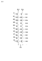
図1は、本実施形態に係るNAND型フラッシュメモリの概略構成を模式的に示した平面図である(ただし、ビット線は図示していない)。図2は、図1に示した構成の等価回路図である。 FIG. 1 is a plan view schematically showing a schematic configuration of the NAND flash memory according to the present embodiment (however, bit lines are not shown). FIG. 2 is an equivalent circuit diagram of the configuration shown in FIG.
図1及び図2に示すように、各NANDセルユニットは、選択トランジスタS1及びS2間に、直列接続されたメモリセルM1〜M8を設けた構成となっている。選択トランジスタS1及びS2には選択ゲート線SG1及びSG2が接続されており、メモリセルM1〜M8にはコントロールゲート線(ワード線)CG1〜CG8が接続されている。また、各選択トランジスタS1には、ビット線BL1及びBL2が接続されている。なお、ここではメモリセルが8個の場合について示したが、メモリセルの数は8個に限定されるものではない。 As shown in FIGS. 1 and 2, each NAND cell unit has a configuration in which memory cells M1 to M8 connected in series are provided between select transistors S1 and S2. Selection gate lines SG1 and SG2 are connected to the selection transistors S1 and S2, and control gate lines (word lines) CG1 to CG8 are connected to the memory cells M1 to M8. In addition, bit lines BL1 and BL2 are connected to each selection transistor S1. Although the case where the number of memory cells is eight is shown here, the number of memory cells is not limited to eight.
図3は図1のA−A’に沿った断面図(ワード線方向の断面図)であり、図4は図1のB−B’に沿った断面図(ビット線方向の断面図)である。 3 is a cross-sectional view (cross-sectional view in the word line direction) along AA ′ in FIG. 1, and FIG. 4 is a cross-sectional view (cross-sectional view in the bit line direction) along BB ′ in FIG. is there.
図3及び図4に示すように、シリコン基板(半導体基板)10上に選択トランジスタS1及びS2並びにメモリセルM1〜M8が形成されている。
As shown in FIGS. 3 and 4, select
各メモリセルM1〜M8は、シリコン基板10上に形成されたトンネル絶縁膜(第1のゲート絶縁膜)11と、ポリシリコン膜12a及び12bで形成されたフローティングゲート電極膜(第1のゲート電極膜)12と、ONO(oxide / nitride / oxide)膜で形成された電極間絶縁膜(第2のゲート絶縁膜)22と、コントロールゲート電極膜(第2のゲート電極膜)23とを備えている。各選択トランジスタS1及びS2は、シリコン基板10上に形成されたゲート絶縁膜11と、ポリシリコン膜12a、12b及びコントロールゲート電極膜23で形成されたゲート電極とを備えている。選択トランジスタS1及びS2並びにメモリセルM1〜M8の側壁には、側壁スペーサ24が形成されている。また、ビット線方向で隣接したメモリセル間には、ソース/ドレイン拡散層25が形成されている。
Each of the memory cells M1 to M8 includes a tunnel insulating film (first gate insulating film) 11 formed on the
ワード線方向で隣接したNANDセルユニット間には、シリコン酸化物を主成分として含む素子分離絶縁部が形成されている。この素子分離絶縁部は、CVD法によって形成されたシリコン酸化膜(CVDシリコン酸化膜:下層酸化物膜)18と、過水素化シラザン重合体(ポリシラザン)から得られたシリコン酸化膜(ポリシラザンシリコン酸化膜:酸化物膜)19bとで形成されている。 An element isolation insulating portion containing silicon oxide as a main component is formed between NAND cell units adjacent in the word line direction. The element isolation insulating portion includes a silicon oxide film (CVD silicon oxide film: lower oxide film) 18 formed by a CVD method and a silicon oxide film (polysilazane silicon oxide) obtained from a perhydrogenated silazane polymer (polysilazane). Film: oxide film) 19b.
選択トランジスタ及びメモリセル等は層間絶縁膜26で覆われている。また、シリコン基板10の表面領域には高濃度拡散層27が形成されており、高濃度拡散層27にはコンタクトプラグ28を介してビット線29が接続されている。
The selection transistor, the memory cell, and the like are covered with an
以下、上述したNAND型フラッシュメモリの製造方法を、図5〜図15を参照して説明する。なお、図5〜図15は、図1のA−A’に沿った断面に対応する。 A method for manufacturing the NAND flash memory described above will be described below with reference to FIGS. 5 to 15 correspond to a cross section taken along the line A-A ′ of FIG. 1.
まず、図5に示すように、シリコン基板(半導体基板)10上に、トンネル絶縁膜11として、厚さ10nm程度のシリコン酸化膜(SiO2 膜)を形成する。続いて、トンネル絶縁膜11上に、フローティングゲート電極膜12として、総厚150nm程度のポリシリコン膜12a及び12bを形成する。さらに、ポリシリコン膜12b上に、厚さ100nm程度のシリコン窒化膜(Si3N4 膜)14を形成する。その後、図6に示すように、シリコン窒化膜14上に、マスク膜15を形成する。
First, as shown in FIG. 5, a silicon oxide film (SiO 2 film) having a thickness of about 10 nm is formed as a
次に、図7に示すように、マスク膜15をパターニングした後、パターニングされたマスク膜15をマスクとして用い、シリコン窒化膜14、フローティングゲート電極膜12、トンネル絶縁膜11及びシリコン基板10を、RIE(reactive ion etching)法によってパターニングする。これにより、深さ450nm程度のSTI(shallow trench isolation)用の素子分離溝16が形成される。
Next, as shown in FIG. 7, after patterning the
なお、図示はしないが、図7の工程の後、素子分離溝16の表面を通常の熱酸化法によって酸化して、厚さ3nm程度の熱酸化膜を形成してもよい。この熱酸化膜により、トンネル絶縁膜11のエッジの露出部を保護することができる。また、ラジカル酸化法によって素子分離溝16の表面に酸化膜を形成してもよい。ラジカル酸化を用いることにより、シリコンの面方位に依存しない均一な酸化膜を形成することが可能である。また、シリコン窒化膜14の側面をわずかに酸化しておいてもよい。
Although not shown, after the step of FIG. 7, the surface of the
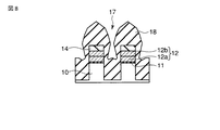
次に、図8に示すように、図7の工程で得られた構造の表面全体に、HDP(high density plasma)−CVD(chemical vapor deposition)法により、CVDシリコン酸化膜(下層酸化物膜)18を堆積する。このとき、素子分離溝16はCVDシリコン酸化膜18によって完全には埋められず、CVDシリコン酸化膜18は素子分離溝16に基づく凹部17を有している。
Next, as shown in FIG. 8, a CVD silicon oxide film (lower oxide film) is formed on the entire surface of the structure obtained in the process of FIG. 7 by HDP (high density plasma) -CVD (chemical vapor deposition) method. 18 is deposited. At this time, the
次に、図9に示すように、図8の工程で得られた被処理体上に、シリコン、水素及び窒素を含有した重合体を含む重合体溶液層として、過水素化シラザン重合体溶液層(ポリシラザン溶液層)19を形成する。具体的には、CVDシリコン酸化膜18上にポリシラザン溶液を、平坦面上での厚さが600nmとなるように、スピンコーティングによって塗布する。
Next, as shown in FIG. 9, a perhydrogenated silazane polymer solution layer as a polymer solution layer containing a polymer containing silicon, hydrogen and nitrogen on the object to be processed obtained in the step of FIG. (Polysilazane solution layer) 19 is formed. Specifically, a polysilazane solution is applied onto the CVD
次に、図10に示すように、ベーク処理によってポリシラザン溶液層19に含まれる溶媒を蒸発させて、過水素化シラザン重合体膜(ポリシラザン膜)19aを形成する。ベーク処理の条件は、例えば150℃で3分間とする。CVDシリコン酸化膜18の凹部17は、ポリシラザン膜19aによって完全に埋められる。
Next, as shown in FIG. 10, the solvent contained in the
次に、図11に示すように、キュア処理を行う。キュア処理により、ポリシラザンがシリコン酸化物(SiO2 )に転化し、シリコン酸化物を主成分として含む酸化物膜として、ポリシラザンシリコン酸化膜19bが得られる。具体的には、水蒸気雰囲気下において高温熱処理を行う。この熱処理により、
(SiH2NH)n + 2nO → nSiO2 + nNH3
という反応が生じる。すなわち、ポリシラザンが水蒸気(H2O+O2)の分解によって生じる酸素(O)又はOH基と反応し、SiO2(シリコン酸化物:シリカ)とNH3(アンモニア)が生成される。なお、素子領域の表面は、シリコン窒化膜14によって覆われているため、酸化されない。
Next, as shown in FIG. 11, a curing process is performed. By the curing treatment, polysilazane is converted into silicon oxide (SiO 2 ), and a polysilazane
(SiH 2 NH) n + 2nO → nSiO 2 + nNH 3
This reaction occurs. That is, polysilazane reacts with oxygen (O) or OH groups generated by the decomposition of water vapor (H 2 O + O 2 ) to generate SiO 2 (silicon oxide: silica) and NH 3 (ammonia). The surface of the element region is not oxidized because it is covered with the
以下、キュア処理におけるシーケンスの詳細を、図16を参照して説明する。 Hereinafter, the details of the sequence in the curing process will be described with reference to FIG.
まず、キュア処理用の反応容器として石英チューブを用意し、この石英チューブ内に、ポリシラザン膜19aが形成された被処理体を搬入する。続いて、反応容器内の圧力が数十mTorr程度となるまで真空排気を行った後、反応容器内の圧力を数十Torr程度に制御する。被処理体の温度は、200℃に制御されている。
First, a quartz tube is prepared as a reaction vessel for curing treatment, and a target object on which a
次に、被処理体の温度を200℃に維持したまま、反応容器内に酸素(O2)及び窒素(N2)の混合ガスを導入する。このとき反応容器内の圧力、すなわちO2/N2混合ガス雰囲気(第1の雰囲気)の圧力が125〜325Torr程度となるようにする。また、混合ガス雰囲気中の酸素分圧が、16Torrから48Torrの範囲内の所望の圧力になるように、O2 及びN2 の流量を制御する。また、窒素分圧が酸素分圧よりも高くなるようにする。例えば、O2/N2混合ガス雰囲気の圧力を325Torr、O2 流量を0.25sLM、N2 流量を4.75sLM、O2分圧を16Torrとする。酸素分圧を16Torrから48Torrの範囲内に設定することにより、後述するように、エッチングのばらつきを抑えることができる。このように設定されたO2/N2混合ガス雰囲気内に、被処理体を5分程度保持する。さらに、O2/N2混合ガス雰囲気内の酸素分圧を維持したまま、被処理体の温度を300℃まで昇温させる。 Next, a mixed gas of oxygen (O 2 ) and nitrogen (N 2 ) is introduced into the reaction vessel while maintaining the temperature of the object to be processed at 200 ° C. At this time, the pressure in the reaction vessel, that is, the pressure of the O 2 / N 2 mixed gas atmosphere (first atmosphere) is set to about 125 to 325 Torr. Further, the flow rates of O 2 and N 2 are controlled so that the oxygen partial pressure in the mixed gas atmosphere becomes a desired pressure within the range of 16 Torr to 48 Torr. Further, the nitrogen partial pressure is made higher than the oxygen partial pressure. For example, the pressure of the O 2 / N 2 mixed gas atmosphere is 325 Torr, the O 2 flow rate is 0.25 sLM, the N 2 flow rate is 4.75 sLM, and the O 2 partial pressure is 16 Torr. By setting the oxygen partial pressure within the range of 16 Torr to 48 Torr, it is possible to suppress variations in etching as will be described later. The object to be processed is held for about 5 minutes in the O 2 / N 2 mixed gas atmosphere thus set. Further, the temperature of the object to be processed is raised to 300 ° C. while maintaining the oxygen partial pressure in the O 2 / N 2 mixed gas atmosphere.
被処理体の温度が300℃±2℃以内に安定した後、N2ガスの供給を止め、水素ガス(H2ガス)の供給を開始する。これにより、O2ガスとH2ガスとが反応して水蒸気(スチーム)が生成される。具体的には、O2ガスとH2ガスとの反応は、反応容器(石英チューブ)の導入部の手前側に配置された反応ユニット(WVG: Water Vaper Generator)で行われる。なお、O2ガス及びH2ガスを反応容器内に導入し、反応容器で水蒸気を生成してもよい。 After the temperature of the object to be processed is stabilized within 300 ° C. ± 2 ° C., supply of N 2 gas is stopped and supply of hydrogen gas (H 2 gas) is started. As a result, the O 2 gas and the H 2 gas react to generate water vapor (steam). Specifically, the reaction between the O 2 gas and the H 2 gas is performed in a reaction unit (WVG: Water Vaper Generator) disposed on the front side of the introduction portion of the reaction vessel (quartz tube). Note that O 2 gas and H 2 gas may be introduced into the reaction vessel to generate water vapor in the reaction vessel.
このようにして得られた水蒸気雰囲気(第2の雰囲気)内で、ポリシラザン膜19aを酸化する。酸化温度は上述したように300℃であり、酸化時間は例えば30分程度である。この水蒸気酸化により、ポリシラザンシリコン酸化膜19bが形成される。
The
次に、上記のようにしてキュア処理が行われたポリシラザンシリコン酸化膜19bに対して、デンシファイ処理を行う。例えば、不活性ガス雰囲気又は酸化性ガス雰囲気において850℃程度の熱処理を行うことで、ポリシラザンシリコン酸化膜19bに残留しているNH3 やH2Oが放出され、より密度の高いシリコン酸化膜が得られる。このときも、素子領域の表面は、シリコン窒化膜14によって覆われているため、酸化されない。なお、デンシファイ処理は、通常の炉を用いて行ってもよいし、RTA(rapid thermal annealing)によって行ってもよい。RTAを用いる場合には、例えば900℃で20秒程度の熱処理を行う。
Next, a densify process is performed on the polysilazane
次に、図12に示すように、CVDシリコン酸化膜18及びポリシラザンシリコン酸化膜19bを、CMP(chemical mechanical polishing)によって平坦化する。CMPでは、シリコン窒化膜14がストッパーとして機能する。コロイダルシリカをベースとした研磨剤を用いてCMPを行うことで、CVDシリコン酸化膜18及びポリシラザンシリコン酸化膜19bの研磨レートに対するシリコン窒化膜14の研磨レートの比を、50以上とすることができる。
Next, as shown in FIG. 12, the CVD
次に、図13に示すように、フッ酸(HF)系のエッチング液によって、CVDシリコン酸化膜18及びポリシラザンシリコン酸化膜19bのエッチバックを行う。その結果、CVDシリコン酸化膜18及びポリシラザンシリコン酸化膜19bの上側部分が除去され、下側部分が素子分離溝内に残る。下側部分の上面の高さは素子分離溝の最上部よりも低くなる。
Next, as shown in FIG. 13, the CVD
すでに述べたように、本実施形態では、水蒸気酸化によってポリシラザン膜19aをポリシラザンシリコン酸化膜19bに転化する前に、O2/N2混合ガス雰囲気中の酸素分圧が16Torrから48Torrの範囲内に設定されている。そのため、後述するように、エッチングのばらつきを抑えることができる。すなわち、素子分離溝の溝幅に依存せず、均一なエッチバック処理を行うことができ、各素子分離溝内に所望の均一な高さで、CVDシリコン酸化膜18及びポリシラザンシリコン酸化膜19bを残すことができる。
As already described, in this embodiment, before the
エッチバック処理を行った後、CVDシリコン酸化膜18及びポリシラザンシリコン酸化膜19bのデンシファイ処理を行う。具体的には、N2ガス雰囲気中で、800℃、1時間の高温・長時間の熱処理を行う。これにより、ポリシラザンシリコン酸化膜19bが十分にデンシファイされる。なお、このデンシファイ処理をエッチバック処理の前に行えば、十分にデンシファイされたポリシラザンシリコン酸化膜19bに対してエッチバック処理を行うことができるため、エッチングのばらつきを抑えることができるのではないかと考えられる。しかしながら、この場合、高温・長時間の熱処理によってポリシラザンシリコン酸化膜19bが十分に硬化しているため、エッチバック処理でのエッチング速度が格段に遅くなる。そのため、長時間のエッチバック処理が必要となり、フローティングゲート電極膜12がダメージを受けるといった問題や、CVDシリコン酸化膜18とポリシラザンシリコン酸化膜19bとの界面で膜剥がれが生じるといった問題が生じる。したがって、上記の高温・長時間のデンシファイ処理は、エッチバック処理を行った後に行う必要がある。
After performing the etch-back process, the CVD
次に、図14に示すように、ホットリン酸をエッチング液として用いて、シリコン窒化膜14を除去する。
Next, as shown in FIG. 14, the
次に、図15に示すように、フローティングゲート電極膜12の表面並びにCVDシリコン酸化膜18及びポリシラザンシリコン酸化膜19bで形成された素子分離部の表面に、ONO膜で形成された電極間絶縁膜22を形成する。続いて、電極間絶縁膜22上に、コントロールゲート電極膜23を形成する。さらに、トンネル絶縁膜11、フローティングゲート電極膜12、電極間絶縁膜22及びコントロールゲート電極膜23を、素子分離溝の延伸方向と垂直な方向にパターニングする。これにより、トンネル絶縁膜11、フローティングゲート電極膜12、電極間絶縁膜22及びコントロールゲート電極膜23で形成されたゲート構造が得られる。さらに、ソース・ドレイン拡散層(図示せず)を形成した後、層間絶縁膜26を形成する。
Next, as shown in FIG. 15, an interelectrode insulating film formed of an ONO film on the surface of the floating
その後の工程は図示しないが、コンタクトや配線の形成等を行い、NAND型フラッシュメモリが形成される。 Although the subsequent steps are not shown, contacts and wirings are formed to form a NAND flash memory.
図17は、キュア処理(水蒸気酸化)を行う前のO2/N2混合ガス雰囲気中の酸素分圧と、エッチバック処理におけるウエハ内でのエッチング速度のばらつきとの関係について、その測定結果を示した図である。測定試料には、同一ウエハ内に複数の溝幅の素子分離溝が形成されたものを用いている。溝幅の最小値は70nm程度、最大値は数十μm程度である。 FIG. 17 shows the measurement results of the relationship between the oxygen partial pressure in the O 2 / N 2 mixed gas atmosphere before the curing process (steam oxidation) and the variation in the etching rate in the wafer in the etch back process. FIG. As the measurement sample, one in which element isolation grooves having a plurality of groove widths are formed in the same wafer is used. The minimum value of the groove width is about 70 nm, and the maximum value is about several tens of μm.
図17に示すように、酸素分圧が16Torrより低い場合及び48Torrよりも高い場合には、同一ウエハ内でエッチング速度が大きくばらついている。これは、主として溝幅に依存してエッチング速度が変化するためである。これに対して、酸素分圧が16Torrから48Torrの範囲にある場合には、エッチング速度のばらつきは3%以下に抑えられている。したがって、酸素分圧を16Torrから48Torrの範囲に設定することで、エッチバック処理におけるエッチング速度のばらつきを十分に抑えることができる。すなわち、エッチバック処理によって形成される素子分離部の高さ(上面の位置)を、同一ウエハ内で均一化することができる。 As shown in FIG. 17, when the oxygen partial pressure is lower than 16 Torr and higher than 48 Torr, the etching rate varies greatly in the same wafer. This is because the etching rate changes mainly depending on the groove width. On the other hand, when the oxygen partial pressure is in the range of 16 Torr to 48 Torr, the variation in the etching rate is suppressed to 3% or less. Therefore, by setting the oxygen partial pressure in the range of 16 Torr to 48 Torr, variations in the etching rate in the etch back process can be sufficiently suppressed. That is, the height (the position of the upper surface) of the element isolation portion formed by the etch back process can be made uniform within the same wafer.
図18及び図19は、エッチバック処理後の試料の断面を示したSEM写真である。図18は本実施形態の方法を用いた場合、図19は従来の方法(酸素分圧が48Torrよりも高い場合)を用いた場合である。図18及び図19を比較すればわかるように、従来の方法を用いた場合には、溝幅に依存して素子分離部の高さが変化しているのに対し、本実施形態の方法を用いた場合には、素子分離部の高さが均一化されている。 18 and 19 are SEM photographs showing a cross section of the sample after the etch-back process. 18 shows a case where the method of the present embodiment is used, and FIG. 19 shows a case where a conventional method (when the oxygen partial pressure is higher than 48 Torr) is used. As can be seen from a comparison of FIGS. 18 and 19, when the conventional method is used, the height of the element isolation portion changes depending on the groove width, whereas the method of this embodiment is used. When used, the height of the element isolation portion is made uniform.
なお、O2/N2混合ガス雰囲気中の酸素分圧を16Torr程度よりも低くした場合には、ウエハ上で多数のパーティクルが検出された。酸素分圧を16Torr以上にすることで、このような問題を回避することもできる。 When the oxygen partial pressure in the O 2 / N 2 mixed gas atmosphere was lower than about 16 Torr, many particles were detected on the wafer. Such a problem can be avoided by setting the oxygen partial pressure to 16 Torr or more.
以上のように、本実施形態では、キュア処理(水蒸気酸化)を行う前のO2/N2混合ガス雰囲気中の酸素分圧を16Torrから48Torrの範囲に設定することにより、エッチバック処理におけるエッチングレートのばらつきを抑えることができ、素子分離部の高さを精度よく制御することができる。 As described above, in the present embodiment, the etching in the etch-back process is performed by setting the oxygen partial pressure in the O 2 / N 2 mixed gas atmosphere before the curing process (steam oxidation) to the range of 16 Torr to 48 Torr. The variation in rate can be suppressed, and the height of the element isolation portion can be controlled with high accuracy.
不揮発性メモリセルでは、トンネル絶縁膜11に基づくキャパシタンスC1と、電極間絶縁膜22に基づくキャパシタンスC2とのキャパシタンス比(カップリング比)が重要である。図15に示すように、電極間絶縁膜22はフローティングゲート電極膜12の上面及び側面に形成されているため、キャパシタンスC2の精度を高めるためには、素子分離絶縁部の上面の高さを正確に制御することが重要である。本実施形態の方法を用いることで、素子分離絶縁部の上面の高さを精度よく制御することができるため、キャパシタンス比のばらつきを低減することが可能である。
In the nonvolatile memory cell, the capacitance ratio (coupling ratio) between the capacitance C1 based on the
(実施形態2)
上述した第1の実施形態では、キュア処理における水蒸気雰囲気の圧力を一定としたが、本実施形態では水蒸気雰囲気の圧力を変化させている。なお、基本的な事項については、第1の実施形態と同様であるため、第1の実施形態で説明した事項については説明を省略する。
(Embodiment 2)
In the first embodiment described above, the pressure of the water vapor atmosphere in the curing process is constant, but in this embodiment, the pressure of the water vapor atmosphere is changed. Since basic matters are the same as those in the first embodiment, descriptions of the matters described in the first embodiment are omitted.
以下、本実施形態におけるキュア処理のシーケンスの詳細を、図20を参照して説明する。 Hereinafter, the details of the sequence of the curing process in the present embodiment will be described with reference to FIG.
キュア処理(水蒸気酸化)前のシーケンスについては第1の実施形態と同様である。すなわち、水蒸気酸化を行う前のO2/N2混合ガス雰囲気中の酸素分圧が、16Torrから48Torrの範囲内の所望の圧力になるようにする。 The sequence before the curing process (steam oxidation) is the same as in the first embodiment. That is, the oxygen partial pressure in the O 2 / N 2 mixed gas atmosphere before the steam oxidation is set to a desired pressure within the range of 16 Torr to 48 Torr.
水蒸気酸化では、まず水蒸気雰囲気の圧力(反応容器内の圧力)を400Torr(第1の圧力)に設定し、5分間の熱処理を行う。続いて、水蒸気雰囲気の圧力を400Torrから700Torr(第2の圧力)の圧力に高め、25分間の熱処理を行う。なお、第1の圧力は325〜400Torrの範囲に、第2の圧力は700〜760Torrの範囲に設定されることが好ましい。 In the steam oxidation, first, the pressure of the steam atmosphere (pressure in the reaction vessel) is set to 400 Torr (first pressure), and heat treatment is performed for 5 minutes. Subsequently, the pressure of the water vapor atmosphere is increased from 400 Torr to 700 Torr (second pressure), and heat treatment is performed for 25 minutes. The first pressure is preferably set in the range of 325 to 400 Torr, and the second pressure is preferably set in the range of 700 to 760 Torr.
このように、水蒸気酸化の際に水蒸気雰囲気の圧力を第1の圧力から第2の圧力に高めることにより、ポリシラザン膜を効率的にポリシラザンシリコン酸化膜に転化することができる。具体的には、シラノール(Si−OH)の残存量が低減すると考えられる。その結果、デンシファイ処理等の熱処理工程におけるポリシラザンシリコン酸化膜の収縮が抑制され、応力を低減することが可能である。 As described above, by increasing the pressure of the steam atmosphere from the first pressure to the second pressure during the steam oxidation, the polysilazane film can be efficiently converted into the polysilazane silicon oxide film. Specifically, it is considered that the residual amount of silanol (Si—OH) is reduced. As a result, the shrinkage of the polysilazane silicon oxide film in the heat treatment step such as densification treatment is suppressed, and the stress can be reduced.
図21は、上述した応力低減効果の測定結果を示した図である。Siウエハ上に形成したポリシラザン膜をキュア処理した試料を用いて応力を求めた。具体的には、ウエハの反りの熱履歴を測定可能な装置を用い、試料の昇温及び降温を行った。800℃までの昇温速度は10℃/分とし、800℃での保持時間を30分とした。応力値σは、ウエハの反りから見積もった曲率半径Rを用いて、以下の式から求めることができる。 FIG. 21 is a diagram showing the measurement results of the stress reduction effect described above. Stress was determined using a sample obtained by curing a polysilazane film formed on a Si wafer. Specifically, the temperature of the sample was raised and lowered using an apparatus capable of measuring the thermal history of wafer warpage. The heating rate up to 800 ° C. was 10 ° C./min, and the holding time at 800 ° C. was 30 minutes. The stress value σ can be obtained from the following equation using the radius of curvature R estimated from the warpage of the wafer.
σ=[E/(1−ν)]×[h2/(6×R×t)]
ただし、νはSiのポアソン比、EはSiのヤング率、tはポリシラザン膜をキュア処理した膜の厚さ、hはSiウエハの厚さである。
σ = [E / (1-ν)] × [h 2 / (6 × R × t)]
Where ν is the Poisson's ratio of Si, E is the Young's modulus of Si, t is the thickness of the polysilazane film cured, and h is the thickness of the Si wafer.
図21からわかるように、本実施形態の方法を用いた場合には、従来の方法を用いた場合に比べて、ピーク応力値が35%程度低減されている。 As can be seen from FIG. 21, when the method of the present embodiment is used, the peak stress value is reduced by about 35% compared to the case where the conventional method is used.
以上のように、本実施形態においても、第1の実施形態と同様、キュア処理(水蒸気酸化)を行う前のO2/N2混合ガス雰囲気中の酸素分圧を16Torrから48Torrの範囲に設定することにより、エッチングレートのばらつきを抑えることができる。さらに、本実施形態では、水蒸気酸化の際に水蒸気雰囲気の圧力を第1の圧力から第2の圧力に高めることにより、ポリシラザンシリコン酸化膜の収縮を抑制することができ、応力を低減することが可能となる。したがって、膜剥がれや欠陥の発生といった問題を回避することが可能である。 As described above, also in this embodiment, the oxygen partial pressure in the O 2 / N 2 mixed gas atmosphere before the curing process (steam oxidation) is set in the range of 16 Torr to 48 Torr as in the first embodiment. By doing so, variation in the etching rate can be suppressed. Furthermore, in the present embodiment, during the steam oxidation, the pressure of the steam atmosphere is increased from the first pressure to the second pressure, so that the shrinkage of the polysilazane silicon oxide film can be suppressed, and the stress can be reduced. It becomes possible. Therefore, problems such as film peeling and generation of defects can be avoided.
なお、上述した第1及び第2の実施形態では、シリコン、水素及び窒素を含有した重合体としてポリシラザンを例に説明したが、熱処理によってシリコン酸化物に転化するような重合体であれば、上述した実施形態と同様の方法を適用することが可能である。 In the first and second embodiments described above, polysilazane has been described as an example of a polymer containing silicon, hydrogen, and nitrogen. However, any polymer that can be converted into silicon oxide by heat treatment may be used as described above. It is possible to apply a method similar to that of the embodiment described above.
以上、本発明の実施形態を説明したが、本発明は上記実施形態に限定されるものではなく、その趣旨を逸脱しない範囲内において種々変形して実施することが可能である。さらに、上記実施形態には種々の段階の発明が含まれており、開示された構成要件を適宜組み合わせることによって種々の発明が抽出され得る。例えば、開示された構成要件からいくつかの構成要件が削除されても、所定の効果が得られるものであれば発明として抽出され得る。 Although the embodiments of the present invention have been described above, the present invention is not limited to the above-described embodiments, and various modifications can be made without departing from the spirit of the present invention. Furthermore, the above embodiments include inventions at various stages, and various inventions can be extracted by appropriately combining the disclosed constituent elements. For example, even if several constituent requirements are deleted from the disclosed constituent requirements, the invention can be extracted as an invention as long as a predetermined effect can be obtained.
10…シリコン基板 11…トンネル絶縁膜
12…フローティングゲート電極膜 14…シリコン窒化膜
15…マスク膜 16…素子分離溝
17…凹部 18…CVDシリコン酸化膜
19…ポリシラザン溶液層 19a…ポリシラザン膜
19b…ポリシラザンシリコン酸化膜
22…電極間絶縁膜 23…コントロールゲート電極膜
24…側壁スペーサ 25…ソース/ドレイン拡散層
26…層間絶縁膜 27…高濃度拡散層
28…コンタクトプラグ 29…ビット線
DESCRIPTION OF
Claims (4)
前記被処理体の主面上に、シリコン、水素及び窒素を含有した重合体を含む重合体膜を形成する工程と、
前記重合体膜が形成された被処理体を、酸素と窒素からなる第1の雰囲気内に保持する工程と、
前記被処理体を前記第1の雰囲気内に保持する工程の後、前記重合体膜を水蒸気を含有した第2の雰囲気内で酸化し、シリコン酸化物を主成分として含む酸化物膜を形成する工程と、
前記酸化物膜の上側部分を除去して、前記酸化物膜の下側部分を前記溝内に残す工程と、
を備え、
前記第1の雰囲気は、前記第1の雰囲気の圧力が125から325Torrの範囲に、且つ酸素分圧が16Torrから48Torrの範囲に設定され、該酸素分圧が窒素分圧よりも低いことを特徴とする半導体装置の製造方法。 Preparing a target object having a groove on the main surface side;
Forming a polymer film containing a polymer containing silicon, hydrogen and nitrogen on the main surface of the object;
Holding the object on which the polymer film is formed in a first atmosphere composed of oxygen and nitrogen ;
After the step of holding the object to be processed in the first atmosphere, the polymer film is oxidized in a second atmosphere containing water vapor to form an oxide film containing silicon oxide as a main component. Process,
Removing the upper portion of the oxide film and leaving the lower portion of the oxide film in the trench;
Equipped with a,
The first atmosphere is characterized in that the pressure of the first atmosphere is set in the range of 125 to 325 Torr, the oxygen partial pressure is set in the range of 16 Torr to 48 Torr, and the oxygen partial pressure is lower than the nitrogen partial pressure. A method for manufacturing a semiconductor device.
前記重合体膜は、前記第2の雰囲気内で前記第2の温度で酸化される
ことを特徴とする請求項1に記載の半導体装置の製造方法。 The object to be processed is heated from a first temperature to a second temperature in the first atmosphere,
The method of manufacturing a semiconductor device according to claim 1, wherein the polymer film is oxidized at the second temperature in the second atmosphere.
ことを特徴とする請求項1に記載の半導体装置の製造方法。 The method of manufacturing a semiconductor device according to claim 1, wherein the step of oxidizing the polymer film includes a step of increasing the pressure of the second atmosphere from the first pressure to the second pressure.
前記重合体膜は前記凹部を埋める
ことを特徴とする請求項1に記載の半導体装置の製造方法。 In the groove, a lower oxide film containing silicon oxide as a main component and having a recess based on the groove is formed in advance,
The method of manufacturing a semiconductor device according to claim 1, wherein the polymer film fills the recess.
Priority Applications (3)
| Application Number | Priority Date | Filing Date | Title |
|---|---|---|---|
| JP2006009031A JP4901221B2 (en) | 2006-01-17 | 2006-01-17 | Manufacturing method of semiconductor device |
| US11/544,747 US7514338B2 (en) | 2006-01-17 | 2006-10-10 | Method of manufacturing a semiconductor device |
| TW095140240A TW200735279A (en) | 2006-01-17 | 2006-10-31 | Manufacturing method for semiconductor device |
Applications Claiming Priority (1)
| Application Number | Priority Date | Filing Date | Title |
|---|---|---|---|
| JP2006009031A JP4901221B2 (en) | 2006-01-17 | 2006-01-17 | Manufacturing method of semiconductor device |
Publications (2)
| Publication Number | Publication Date |
|---|---|
| JP2007194286A JP2007194286A (en) | 2007-08-02 |
| JP4901221B2 true JP4901221B2 (en) | 2012-03-21 |
Family
ID=38263746
Family Applications (1)
| Application Number | Title | Priority Date | Filing Date |
|---|---|---|---|
| JP2006009031A Active JP4901221B2 (en) | 2006-01-17 | 2006-01-17 | Manufacturing method of semiconductor device |
Country Status (3)
| Country | Link |
|---|---|
| US (1) | US7514338B2 (en) |
| JP (1) | JP4901221B2 (en) |
| TW (1) | TW200735279A (en) |
Families Citing this family (7)
| Publication number | Priority date | Publication date | Assignee | Title |
|---|---|---|---|---|
| JP2008103645A (en) * | 2006-10-20 | 2008-05-01 | Toshiba Corp | Production method of semiconductor device |
| KR20080061022A (en) * | 2006-12-27 | 2008-07-02 | 동부일렉트로닉스 주식회사 | Method of manufacturing flash memory device |
| US7915126B2 (en) * | 2007-02-14 | 2011-03-29 | Micron Technology, Inc. | Methods of forming non-volatile memory cells, and methods of forming NAND cell unit string gates |
| JP2010027904A (en) * | 2008-07-22 | 2010-02-04 | Elpida Memory Inc | Method of manufacturing semiconductor device |
| KR20110096843A (en) * | 2010-02-23 | 2011-08-31 | 삼성전자주식회사 | Method of manufacturing semiconductor device |
| JP5670777B2 (en) * | 2011-02-10 | 2015-02-18 | ルネサスエレクトロニクス株式会社 | Manufacturing method of semiconductor device |
| US9240494B2 (en) | 2012-08-15 | 2016-01-19 | Kabushiki Kaisha Toshiba | Semiconductor device and method for fabricating semiconductor device |
Family Cites Families (10)
| Publication number | Priority date | Publication date | Assignee | Title |
|---|---|---|---|---|
| JP3916284B2 (en) * | 1997-02-28 | 2007-05-16 | 東京応化工業株式会社 | Method for forming multilayer wiring structure |
| JP5020425B2 (en) * | 2000-04-25 | 2012-09-05 | Azエレクトロニックマテリアルズ株式会社 | Method for embedding fine grooves with siliceous material |
| KR100568100B1 (en) * | 2001-03-05 | 2006-04-05 | 삼성전자주식회사 | Method of forming insulation layer in trench isolation type semiconductor device |
| JP2003258082A (en) | 2002-03-04 | 2003-09-12 | Toshiba Corp | Manufacturing method for semiconductor device |
| JP4342895B2 (en) * | 2003-10-06 | 2009-10-14 | 東京エレクトロン株式会社 | Heat treatment method and heat treatment apparatus |
| JP2005150502A (en) * | 2003-11-18 | 2005-06-09 | Toshiba Corp | Method of manufacturing semiconductor device |
| JP2005150500A (en) * | 2003-11-18 | 2005-06-09 | Toshiba Corp | Semiconductor device and its manufacturing method |
| JP2005347636A (en) * | 2004-06-04 | 2005-12-15 | Az Electronic Materials Kk | Method for forming trench isolation structure |
| JP4607613B2 (en) * | 2005-02-09 | 2011-01-05 | 株式会社東芝 | Manufacturing method of semiconductor device |
| US7682927B2 (en) * | 2005-03-25 | 2010-03-23 | Kabushiki Kaisha Toshiba | Method of manufacturing semiconductor device |
-
2006
- 2006-01-17 JP JP2006009031A patent/JP4901221B2/en active Active
- 2006-10-10 US US11/544,747 patent/US7514338B2/en not_active Expired - Fee Related
- 2006-10-31 TW TW095140240A patent/TW200735279A/en not_active IP Right Cessation
Also Published As
| Publication number | Publication date |
|---|---|
| JP2007194286A (en) | 2007-08-02 |
| US7514338B2 (en) | 2009-04-07 |
| TWI326904B (en) | 2010-07-01 |
| TW200735279A (en) | 2007-09-16 |
| US20070166951A1 (en) | 2007-07-19 |
Similar Documents
| Publication | Publication Date | Title |
|---|---|---|
| JP4672400B2 (en) | Perhydrogenated polysilazane solution and method for manufacturing semiconductor device using the same | |
| JP4509868B2 (en) | Manufacturing method of semiconductor device | |
| US7538047B2 (en) | Method of manufacturing semiconductor device | |
| JP4607613B2 (en) | Manufacturing method of semiconductor device | |
| TWI400755B (en) | Dielectric deposition and etch back processes for bottom up gapfill | |
| KR100839529B1 (en) | Method for fabricating isolation in semiconductor device | |
| JP4901221B2 (en) | Manufacturing method of semiconductor device | |
| JP2007221058A (en) | Method for manufacturing semiconductor device | |
| WO2014115600A1 (en) | Method for manufacturing semiconductor device | |
| JP2003045957A (en) | Method of isolating elements of semiconductor device | |
| KR20100082170A (en) | Methods of forming a silicon oxide layer pattern and an isolation layer | |
| KR20090067576A (en) | Method of filling a trench and method of forming an isolation layer structure using the same | |
| JP4417882B2 (en) | Manufacturing method of semiconductor device | |
| JP4282692B2 (en) | Manufacturing method of semiconductor device | |
| JP2005045230A (en) | Method for forming silicone oxide film with spin-on glass | |
| JP2008078627A (en) | Manufacturing method of semiconductor device | |
| JP2007142155A (en) | Oxidation treatment method and manufacturing method of semiconductor device | |
| JP4594648B2 (en) | Semiconductor device and manufacturing method thereof | |
| US20070004139A1 (en) | Method of manufacturing a non-volatile semiconductor device | |
| JP2008177277A (en) | Flash memory and method for manufacturing the same | |
| TWI320214B (en) | Method of forming a trench isolation structure | |
| JP4331133B2 (en) | Manufacturing method of semiconductor device | |
| JP2010050145A (en) | Method for manufacturing element isolation structure, and element isolation structure | |
| CN106024699A (en) | Preparation method for self-alignment STI (shallow trench isolation) | |
| JP2008010884A (en) | Method of manufacturing semiconductor device |
Legal Events
| Date | Code | Title | Description |
|---|---|---|---|
| A621 | Written request for application examination |
Free format text: JAPANESE INTERMEDIATE CODE: A621 Effective date: 20080728 |
|
| A977 | Report on retrieval |
Free format text: JAPANESE INTERMEDIATE CODE: A971007 Effective date: 20110726 |
|
| A131 | Notification of reasons for refusal |
Free format text: JAPANESE INTERMEDIATE CODE: A131 Effective date: 20110802 |
|
| A521 | Request for written amendment filed |
Free format text: JAPANESE INTERMEDIATE CODE: A523 Effective date: 20110928 |
|
| TRDD | Decision of grant or rejection written | ||
| A01 | Written decision to grant a patent or to grant a registration (utility model) |
Free format text: JAPANESE INTERMEDIATE CODE: A01 Effective date: 20111206 |
|
| A01 | Written decision to grant a patent or to grant a registration (utility model) |
Free format text: JAPANESE INTERMEDIATE CODE: A01 |
|
| A61 | First payment of annual fees (during grant procedure) |
Free format text: JAPANESE INTERMEDIATE CODE: A61 Effective date: 20111227 |
|
| R151 | Written notification of patent or utility model registration |
Ref document number: 4901221 Country of ref document: JP Free format text: JAPANESE INTERMEDIATE CODE: R151 |
|
| FPAY | Renewal fee payment (event date is renewal date of database) |
Free format text: PAYMENT UNTIL: 20150113 Year of fee payment: 3 |
|
| S111 | Request for change of ownership or part of ownership |
Free format text: JAPANESE INTERMEDIATE CODE: R313111 |
|
| R350 | Written notification of registration of transfer |
Free format text: JAPANESE INTERMEDIATE CODE: R350 |
|
| S111 | Request for change of ownership or part of ownership |
Free format text: JAPANESE INTERMEDIATE CODE: R313111 |
|
| R350 | Written notification of registration of transfer |
Free format text: JAPANESE INTERMEDIATE CODE: R350 |