JP4899991B2 - Display device and program - Google Patents
Display device and program Download PDFInfo
- Publication number
- JP4899991B2 JP4899991B2 JP2007090364A JP2007090364A JP4899991B2 JP 4899991 B2 JP4899991 B2 JP 4899991B2 JP 2007090364 A JP2007090364 A JP 2007090364A JP 2007090364 A JP2007090364 A JP 2007090364A JP 4899991 B2 JP4899991 B2 JP 4899991B2
- Authority
- JP
- Japan
- Prior art keywords
- menu image
- hierarchy
- menu
- image
- selection item
- Prior art date
- Legal status (The legal status is an assumption and is not a legal conclusion. Google has not performed a legal analysis and makes no representation as to the accuracy of the status listed.)
- Active
Links
Images


Classifications
-
- G—PHYSICS
- G06—COMPUTING; CALCULATING OR COUNTING
- G06F—ELECTRIC DIGITAL DATA PROCESSING
- G06F3/00—Input arrangements for transferring data to be processed into a form capable of being handled by the computer; Output arrangements for transferring data from processing unit to output unit, e.g. interface arrangements
- G06F3/01—Input arrangements or combined input and output arrangements for interaction between user and computer
- G06F3/048—Interaction techniques based on graphical user interfaces [GUI]
- G06F3/0487—Interaction techniques based on graphical user interfaces [GUI] using specific features provided by the input device, e.g. functions controlled by the rotation of a mouse with dual sensing arrangements, or of the nature of the input device, e.g. tap gestures based on pressure sensed by a digitiser
- G06F3/0488—Interaction techniques based on graphical user interfaces [GUI] using specific features provided by the input device, e.g. functions controlled by the rotation of a mouse with dual sensing arrangements, or of the nature of the input device, e.g. tap gestures based on pressure sensed by a digitiser using a touch-screen or digitiser, e.g. input of commands through traced gestures
-
- G—PHYSICS
- G06—COMPUTING; CALCULATING OR COUNTING
- G06F—ELECTRIC DIGITAL DATA PROCESSING
- G06F3/00—Input arrangements for transferring data to be processed into a form capable of being handled by the computer; Output arrangements for transferring data from processing unit to output unit, e.g. interface arrangements
- G06F3/01—Input arrangements or combined input and output arrangements for interaction between user and computer
- G06F3/048—Interaction techniques based on graphical user interfaces [GUI]
- G06F3/0481—Interaction techniques based on graphical user interfaces [GUI] based on specific properties of the displayed interaction object or a metaphor-based environment, e.g. interaction with desktop elements like windows or icons, or assisted by a cursor's changing behaviour or appearance
- G06F3/0482—Interaction with lists of selectable items, e.g. menus
Description
本発明は、メニュー表示を行う表示装置、プログラムに関する。 The present invention relates to a display device and a program for displaying a menu.
マウスのクリックといった外部コマンドに応答してアイテムの極座標を生成し、その極座標に従ってアイテムの画像を生成するマルチユーザコラボラティブ円形グラフィカルユーザインタフェースが知られている(例えば、特許文献1参照)。
また、表示画面に重なる入力領域を有するタッチ入力部を備え、第1のタッチT1のタッチ位置を中心としてほぼ環状に配置された複数のメニュー項目を含む円形メニューを表示画面上に表示し、第2のタッチT2に応じて、第1のタッチに対する第2のタッチの相対位置関係に応じて、どのメニュー項目が選択されたかを決定するメニュー表示技術が知られている(例えば、特許文献2参照)。
A multi-user collaborative circular graphical user interface that generates polar coordinates of an item in response to an external command such as a mouse click and generates an image of the item according to the polar coordinates is known (for example, see Patent Document 1).
A touch input unit having an input area overlapping the display screen; and a circular menu including a plurality of menu items arranged in a ring shape around the touch position of the first touch T1 is displayed on the display screen. A menu display technique for determining which menu item is selected according to the relative positional relationship of the second touch with respect to the first touch according to the second touch T2 is known (see, for example, Patent Document 2). ).
本発明の目的は、テーブルの天板等に表示画面が設置されたディスプレイ装置に対して、ディスプレイ装置の表示画面を囲む様々な方向から操作することが容易なメニューの表示を実現することにある。 An object of the present invention is to realize a menu display that can be easily operated from various directions surrounding a display screen of a display device on a display device having a display screen installed on a table top or the like. .
請求項1に記載の発明は、
メニューの選択項目を幾何学的に配列したメニュー画像を生成する生成手段と、
ディスプレイ装置の画面上に前記メニュー画像を表示させ、当該メニュー画像における前記選択項目の位置を動的に変化させる制御手段と、
前記ディスプレイ装置の画面に表示されたオブジェクト画像の位置を認識し、当該オブジェクト画像と前記メニュー画像とが重ならないように当該メニュー画像の表示位置を決定する決定手段とを備え、
前記制御手段は、前記決定手段により決定された位置に前記メニュー画像を表示させることを特徴とする表示装置である。
請求項2に記載の発明は、
前記生成手段は、前記選択項目が所定の円周上を回転移動する動画ファイルとして前記メニュー画像を生成し、
前記制御手段は、前記メニュー画像の動画ファイルを前記ディスプレイ装置の画面上で再生させることにより、前記選択項目の位置を変化させることを特徴とする請求項1に記載の表示装置である。
請求項3に記載の発明は、
前記生成手段は、一定領域内の異なる位置に前記選択項目が配置された複数の前記メニュー画像を生成し、
前記制御手段は、複数の前記メニュー画像を切り換えながら前記ディスプレイ装置の画面に表示させることにより、前記選択項目の位置を変化させることを特徴とする請求項1に記載の表示装置である。
請求項4に記載の発明は、
前記生成手段は、個別に生成された前記選択項目ごとの画像の組み合わせにより前記メニュー画像を生成し、
前記制御手段は、前記選択項目と同数またはそれ以上の数の当該選択項目の配置位置を設定し、各配置位置に表示される選択項目を順次切り替えることにより、当該選択項目の位置を変化させることを特徴とする請求項1に記載の表示装置である。
請求項5に記載の発明は、
前記制御手段は、前記選択項目の位置の変化速度を動的に変化させることを特徴とする請求項1に記載の表示装置である。
請求項6に記載の発明は、
前記生成手段は、階層的に設定されたメニューの各階層に関して個別に前記メニュー画像を生成し、
前記制御手段は、表示されているメニュー画像に含まれる選択項目のうちで下位の階層に関連付けられた選択項目が選択された場合に、当該下位の階層のメニュー画像を前記ディスプレイ装置の画面に表示させることを特徴とする請求項1に記載の表示装置である。
請求項7に記載の発明は、
前記生成手段は、前記階層ごとに当該階層における前記選択項目を円周上に配列したメニュー画像を生成し、
前記制御手段は、所定の前記選択項目が選択された場合に、当該選択項目を前記円周の中心点として、当該選択項目に関連付けられた階層の前記メニュー画像を表示することを特徴とする請求項6に記載の表示装置である。
請求項8に記載の発明は、
前記制御手段は、
前記メニュー画像において円周上に配列された前記選択項目の位置を当該円周の中心点の周りに回転移動させ、
新たな階層の前記メニュー画像が表示された場合は、当該新たな階層より上位の階層の前記メニュー画像についての前記選択項目の回転移動を停止させる
ことを特徴とする請求項7に記載の表示装置である。
請求項9に記載の発明は、
前記生成手段は、2段目以下の前記階層に対して、前記選択項目を直線的に配列したメニュー画像を生成し、
前記制御手段は、所定の前記選択項目が選択された場合に、当該選択項目を基点として、当該選択項目に関連付けられた階層の前記メニュー画像を、直線的に配列された前記選択項目が一定の方向に伸びるように表示することを特徴とする請求項6に記載の表示装置である。
請求項10に記載の発明は、
前記制御手段は、
新たな階層の前記選択項目についての前記一定の方向が最後に表示された階層の前記選択項目についての前記一定の方向に対し左方または右方に伸びる方向であるように、当該新たな階層の前記メニュー画像を表示し、
最後に表示された階層における前記一定の方向が当該最後に表示された階層の直前の階層における前記一定の方向に対し左方である場合に、新たな階層における前記一定の方向が当該最後に表示された階層における当該一定の方向に対し右方であるように、
最後に表示された階層における前記一定の方向が当該最後に表示された階層の直前の階層における前記一定の方向に対し右方である場合に、新たな階層における前記一定の方向が当該最後に表示された階層における当該一定の方向に対し左方であるように、
当該新たな階層の前記メニュー画像を表示することを特徴とする請求項9に記載の表示装置である。
請求項11に記載の発明は、
前記生成手段は、前記各階層について交互に、1つの階層における前記選択項目を円周上に配列した第1のメニュー画像または当該選択項目を直線的に配列した第2のメニュー画像を生成し、
前記制御手段は、
前記第1のメニュー画像に含まれる所定の前記選択項目が選択された場合に、当該選択項目を基点として、当該選択項目に関連付けられた下位の階層の前記第2のメニュー画像を、当該下位の階層の直線的に配列された前記選択項目が一定の方向に伸びるように表示し、
前記第2のメニュー画像に含まれる所定の前記選択項目が選択された場合に、当該選択項目を前記円周の中心点として、当該選択項目に関連付けられた下位の階層の前記第1のメニュー画像を表示する
ことを特徴とする請求項6に記載の表示装置である。
請求項12に記載の発明は、
前記生成手段は、2段目以降の前記階層に対して、当該階層の選択項目を、1段上の階層のメニュー画像の外周に相当する円周上に配列したメニュー画像を生成し、
前記制御手段は、所定の前記選択項目が選択された場合に、当該選択項目に関連付けられた階層の前記メニュー画像を、当該選択項目が含まれる階層のメニュー画像の外側に表示することを特徴とする請求項6に記載の表示装置である。
請求項13に記載の発明は、
前記生成手段は、メニューの選択項目を円周上に複数個配列したメニュー画像を生成し、
前記制御手段は、ディスプレイ装置の画面であって複数のユーザが取り囲んで見ることができる画面上に当該複数のユーザが複数の方向から前記選択項目のそれぞれを操作可能であるように前記メニュー画像を表示させ、予め定めた時間ごとに当該メニュー画像における前記選択項目のそれぞれが当該複数のユーザのいずれにとっても前記円周の中心点に対して手前側に来るように当該選択項目の位置を動的に変化させることを特徴とする請求項1に記載の表示装置である。
請求項14に記載の発明は、
コンピュータに、
メニューの選択項目を円周上に配列したメニュー画像を生成する機能と、
ディスプレイ装置の画面上に前記メニュー画像を表示させ、当該メニュー画像における前記選択項目の前記円周上における位置を動的に変化させる制御機能と、
前記ディスプレイ装置の画面に表示されたオブジェクト画像の位置を認識し、当該オブジェクト画像と前記メニュー画像とが重ならないように当該メニュー画像の表示位置を決定する機能とを実現させ、
前記制御機能は、前記決定する機能により決定された位置に前記メニュー画像を表示させることを特徴とするプログラムである。
The invention described in
Generating means for generating a menu image in which menu selection items are geometrically arranged;
Control means for displaying the menu image on a screen of a display device and dynamically changing the position of the selection item in the menu image ;
Recognizing the position of the object image displayed on the screen of the display device, and determining means for determining the display position of the menu image so that the object image and the menu image do not overlap,
Wherein said control means is a display device characterized Rukoto to display the menu image on the position determined by said determining means.
The invention described in
The generation unit generates the menu image as a moving image file in which the selection item rotates on a predetermined circumference,
The display device according to
The invention according to
The generation means generates a plurality of the menu images in which the selection items are arranged at different positions in a certain area,
2. The display device according to
The invention according to
The generating means generates the menu image by combining images for each of the selection items generated individually,
The control means sets an arrangement position of the selection items of the same number or more as the selection items, and changes the position of the selection items by sequentially switching the selection items displayed at the respective arrangement positions. The display device according to
The invention described in
The display device according to
The invention described in
The generation means generates the menu image individually for each hierarchy of menus set hierarchically,
The control means displays the menu image of the lower hierarchy on the screen of the display device when a selection item associated with the lower hierarchy is selected from the selection items included in the displayed menu image. The display device according to
The invention described in claim 7
The generating means generates a menu image in which the selection items in the hierarchy are arranged on a circumference for each hierarchy,
The control means, when a predetermined selection item is selected, displays the menu image of a hierarchy associated with the selection item with the selection item as a center point of the circumference. Item 7. The display device according to
The invention according to claim 8 provides:
The control means includes
Rotating the position of the selection items arranged on the circumference in the menu image around the center point of the circumference;
When the menu image of a new hierarchy is displayed, the rotational movement of the selection item for the menu image of a hierarchy higher than the new hierarchy is stopped.
The display device according to claim 7.
The invention according to
The generating means generates a menu image in which the selection items are linearly arranged for the second and lower layers.
When the predetermined selection item is selected, the control means uses the selection item as a base point, the menu image of the hierarchy associated with the selection item, the selection items arranged linearly are fixed. The display device according to
The invention according to claim 10 is:
The control means includes
The new direction of the new hierarchy is such that the constant direction for the selection item of the new hierarchy is a direction that extends to the left or right with respect to the constant direction for the selection item of the last displayed hierarchy. Display the menu image,
If the certain direction in the last displayed hierarchy is to the left of the certain direction in the hierarchy immediately before the last displayed hierarchy, the certain direction in the new hierarchy is displayed last. To the right of the given direction in the given hierarchy,
If the certain direction in the last displayed hierarchy is to the right of the certain direction in the hierarchy immediately before the last displayed hierarchy, the certain direction in the new hierarchy is displayed last. To the left of the given direction in the given hierarchy,
The display device according to
The invention according to
The generating means alternately generates a first menu image in which the selection items in one layer are arranged on the circumference or a second menu image in which the selection items are linearly arranged for each of the layers,
The control means includes
When the predetermined selection item included in the first menu image is selected, the second menu image in the lower hierarchy associated with the selection item is used as the lower level, with the selection item as a base point. Display the selection items arranged in a straight line of the hierarchy so as to extend in a certain direction,
When the predetermined selection item included in the second menu image is selected, the first menu image in the lower hierarchy associated with the selection item with the selection item as the center point of the circumference Display
The display device according to
The invention according to claim 12
The generation unit generates a menu image in which selection items of the hierarchy are arranged on a circumference corresponding to the outer periphery of the menu image of the hierarchy one level higher than the hierarchy in the second stage,
When the predetermined selection item is selected, the control means displays the menu image of the hierarchy associated with the selection item outside the menu image of the hierarchy including the selection item. The display device according to
The invention according to
The generating means generates a menu image in which a plurality of menu selection items are arranged on the circumference,
The control means displays the menu image so that the plurality of users can operate each of the selection items from a plurality of directions on a screen of a display device that can be surrounded and viewed by the plurality of users. The position of the selection item is dynamically displayed so that each of the selection items in the menu image comes closer to the center point of the circumference for each of the plurality of users at predetermined time intervals. The display device according to
The invention according to claim 14
On the computer,
A function for generating a menu image in which menu selection items are arranged on the circumference;
A control function for displaying the menu image on a screen of a display device and dynamically changing a position on the circumference of the selection item in the menu image ;
Realizing the function of recognizing the position of the object image displayed on the screen of the display device and determining the display position of the menu image so that the object image and the menu image do not overlap ,
The control function is a program characterized Rukoto to display the menu image on the position determined by the function that said determining.
請求項1の発明は、メニュー画像の選択項目の位置を動的に変化させて、画面を囲む様々な方向からの操作の良いメニューを提供でき、メニュー画像が画面上の他のオブジェクト画像と重ならず、視認性を高められるという効果がある。
請求項2の発明は、メニュー画像を動画により滑らかに回転させられるという効果がある。
請求項3の発明は、動画ファイルを用いずにメニュー画面を回転表示させることができるという効果がある。
請求項4の発明は、選択項目ごとに柔軟に表示制御できるという効果がある。
請求項5の発明は、メニュー画像の回転速度を変化させて操作性を高めることができるという効果がある。
請求項6の発明は、メニューの階層表示を実現できるという効果がある。
請求項7の発明は、各階層とも同様の操作性を発揮できるという効果がある。
請求項8の発明は、画面を囲むどの方向からでも操作しやすいメニューを提供できるという効果がある。
請求項9の発明は、選択項目の直線的な配列の組み合わせにより各選択項目の階層の深さを直感的に容易に把握できるという効果がある。
請求項10の発明は、第1階層から遠い(深い)階層へ進んでいることが直感的に把握しやすいという効果がある。
請求項11の発明は、各階層とも同様の操作性を発揮でき、選択項目の直線的な配列の組み合わせにより各選択項目の階層の深さを直感的に容易に把握できるという効果がある。
請求項12の発明は、階層ごとの選択項目を重層的に配列し、各選択項目の階層の深さを直感的に容易に把握できるという効果がある。
請求項13の発明は、画面を囲むどの方向からでも操作しやすいメニューを提供できるという効果がある。
請求項14の発明は、コンピュータにより、メニュー画像の選択項目の位置を動的に変化させて、画面を囲む様々な方向からの操作の良いメニューを提供でき、メニュー画像が画面上の他のオブジェクト画像と重ならず、視認性を高められるという効果がある。
According to the first aspect of the present invention, it is possible to provide a menu with good operation from various directions surrounding the screen by dynamically changing the position of the selection item of the menu image, and the menu image overlaps with other object images on the screen. Narazu, there is an effect that Ru enhanced visibility.
The invention of
The invention of
The invention of
The invention of
The invention of
The invention of claim 7 has an effect that the same operability can be exhibited in each layer.
The invention of claim 8 has an effect that it is possible to provide a menu that is easy to operate from any direction surrounding the screen.
The invention of
The invention of claim 10 has an effect that it is easy to intuitively understand that the vehicle is moving from a first layer to a far (deep) layer.
The invention of
The invention of claim 12 has an effect that the selection items for each hierarchy are arranged in a multi-layered manner, and the depth of the hierarchy of each selection item can be intuitively and easily grasped.
The invention of
According to the fourteenth aspect of the present invention, the computer can dynamically change the position of the selection item of the menu image to provide a menu with good operation from various directions surrounding the screen. not overlap the image, there is an effect that Ru enhanced visibility.
以下、添付図面を参照して、本発明を実施するための最良の形態(以下、実施形態という)について詳細に説明する。
<テーブル型表示装置の機構>
本実施形態では、表示装置の一例として、複数のユーザが取り囲んで議論等を行うためのテーブル型表示装置を用いた。そこで、まず、このテーブル型表示装置の機構について説明する。
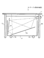
図1は、本実施形態におけるテーブル型表示装置の断面図である。
図示するように、テーブル型表示装置10は、議論等を行う作業台としての天板11と、天板11を支持する脚部12a〜12dとを備える。また、天板11に対して背面から画像を投影する投影ユニット13と、投影ユニット13を移動自在に支持するキャスター14a〜14dと、天板11に投影させる画像を映し出すプロジェクタ15とを備える。ただし、図1は断面図のため、脚部12c及び12d、キャスター14c及び14dについては、図に現れていない。また、図1には示していないが、各種の演算処理を行い、プロジェクタ15および投影ユニット13を介して天板11の画面に表示される画像を出力する演算ユニットが存在する。この演算ユニットは、テーブル型表示装置10の内蔵コンピュータとして設けても良いし、外部コンピュータとして実現されプロジェクタ15に接続されても良い。
The best mode for carrying out the present invention (hereinafter referred to as an embodiment) will be described below in detail with reference to the accompanying drawings.
<Mechanism of table type display device>
In the present embodiment, a table type display device is used as an example of a display device for a plurality of users to surround and discuss. First, the mechanism of this table type display device will be described.
FIG. 1 is a cross-sectional view of a table type display device in the present embodiment.
As shown in the figure, the table-type display device 10 includes a
天板11は、その周囲の任意の位置にユーザが立って議論等に参加できるよう、例えば、円形のものを用いる。また、例えばガラス板等の基材に乳白色の半透明フィルターを貼り付け、投影ユニット13により投影された画像を表示する表示画面として機能させる。すなわち、本実施形態では、表示手段の一例として、天板11を用いた。更に、表示された画像に対するユーザの操作を検知するタッチパネルの機能も備える。ここで、タッチパネルは、天板11の表面を接触を検知するための素子を配置した透明なスクリーンで覆うことで実現しても良いし、天板11の表面で縦、横に赤外光を走らせてその遮断された位置を検出することで実現しても良い。
脚部12a〜12dは、4本脚の場合の例であるが、脚部の数はこれに限らない。
The
The
投影ユニット13は、天板11の側の面が開いた四角柱の箱からなっており、その中にミラー13a及び13bを備える。ここで、ミラー13a及び13bは、図のような角度で固定され、投影ユニット13の箱の側面に取り付けられているものとする。
The
キャスター14a〜14dは、天板11、脚部12a〜12d、プロジェクタ15からなるテーブルの移動に合わせて投影ユニット13を動かせるよう、投影ユニット13の底面に取り付けられている。ただし、テーブルに対する投影ユニット13の相対的位置がずれることのないようにする。なお、ここでは、キャスターを4つとしたが、その数はこれに限らない。
The
プロジェクタ15は、天板11の下に吊り下げられて固定され、ミラー13aの方向に画像を投影する。すると、その画像はミラー13bで反射し、天板11に投影されることになる。
The
なお、ここでは、テーブル型表示装置10を例として示したが、本実施形態は、テーブル型だけでなく、如何なる形状の表示装置に対して適用しても良い。また、表示手段の構成も、上述したプロジェクタ15から投影ユニット13を介して天板11に画像を投影するものに限られず、液晶ディスプレイやプラズマディスプレイ等のフラットパネルディスプレイ、CRTディスプレイ、その他の種々の表示装置を用いて実現しても良い。
Here, the table type display device 10 is shown as an example, but the present embodiment may be applied not only to the table type but also to any shape display device. Also, the configuration of the display means is not limited to the above-described
<表示画面の構成>
次に、テーブル型表示装置10の表示画面の構成例を説明する。
図2は、テーブル型表示装置10を上面から見た図である。
図では、太い実線によりテーブルの縁(天板11の輪郭)を表している。なお、ここでは、テーブルの縁を楕円形にしたが、必ずしも楕円形でなくて良く、例えば、円形や矩形であっても構わない。
<Configuration of display screen>
Next, a configuration example of the display screen of the table type display device 10 will be described.
FIG. 2 is a view of the table-type display device 10 as viewed from above.
In the figure, the edge of the table (the contour of the top plate 11) is represented by a thick solid line. Here, the edge of the table is elliptical, but it is not necessarily elliptical. For example, it may be circular or rectangular.
また、ここでは、天板11の内部に画面が設けられている。図では、細い実線により画面の縁を表している。この画面には電子文書を表す画像(以下、単に「電子文書」ということもある)が表示されるので、この画面内の領域は「表示領域」である。なお、ここでは、画面の縁を矩形にしたが、これも必ず矩形にしなければならないというものではない。例えば、テーブルの縁の形状に沿った楕円形としても良いし、その他の形状にしても良い。
Here, a screen is provided inside the
なお、本明細書では、紙等の記録媒体に記録する画像の元となる電子データを「電子文書」と表記するが、これは、テキストを含む「文書」を電子化したデータのみを意味するものではない。例えば、絵、写真、図形等の画像データ(ラスタデータかベクターデータかによらない)、データベース管理ソフトウェアや表計算ソフトウェアで記録されるデータ、その他の印刷可能な電子データも含めて「電子文書」としている。 In this specification, electronic data that is the basis of an image to be recorded on a recording medium such as paper is referred to as “electronic document”, which means only data obtained by digitizing a “document” including text. It is not a thing. For example, "electronic document" including image data such as pictures, photos, figures (regardless of raster data or vector data), data recorded by database management software or spreadsheet software, and other printable electronic data It is said.
<テーブル型表示装置の機能構成>
次に、本実施形態のテーブル型表示装置10における演算ユニットの機能構成について説明する。
図3は、本実施形態の演算ユニット機能構成の一例を示したブロック図である。
図示するように、テーブル型表示装置10は、画面上でのユーザ操作を検出する操作検出部110と、画面上でのユーザ操作に基づきメニュー表示を行うメニュー表示部120と、ユーザによる画面上でのメニュー操作に応じてコマンド(命令)を出力するコマンド出力部130と、画面上に表示されているオブジェクト画像の位置に関する情報を記憶する画像位置記憶部140とを備える。ここで、オブジェクト画像とは、画面上に表示されている各種のオブジェクトの画像を意味するが、主として電子文書が該当する。
<Functional configuration of table type display device>
Next, the functional configuration of the arithmetic unit in the table type display device 10 of the present embodiment will be described.
FIG. 3 is a block diagram showing an example of the functional unit functional configuration of the present embodiment.
As shown in the figure, the table type display device 10 includes an
操作検出部110は、天板11(図1参照)に備わるタッチパネルに対する指でのタッチをタッチパネルが検知して出力される信号を受け付けることで、ユーザ操作を検出する。すなわち、本実施形態では、操作を検出する検出手段の一例として、操作検出部110を設けた。ここで、指でのタッチに関する信号には、指がタッチパネルに触れたことを示す信号(タッチON信号)、指がタッチパネルから離れたことを示す信号(タッチOFF信号)、指がタッチパネルに触れた状態でタッチパネル上を移動(ドラッグ)されたことを示す信号(ドラッグ信号)がある。このうち、タッチON信号、タッチOFF信号は、それぞれ、指がタッチした位置、指が離れた位置を伝える。また、ドラッグ信号は、タッチON信号が伝えられてからタッチOFF信号が伝えられるまでの指が移動する経路の位置を極めて短い時間間隔で伝える。
The
メニュー表示部120は、操作検出部110が検出したユーザの操作内容を受け取り、その操作内容に応じてメニュー画像の表示、変更、消去等の処理を行う。なお、本実施形態においてメニューとは、テーブル型表示装置10の表示画面にGUI表示される選択項目である。各項目は、項目の内容を表すテキストやアイコン画像により表現される。ユーザは、このメニューに表示された項目を選択することにより、アプリケーションに所望の処理を実行させる。
図3に示すように、本実施形態のメニュー表示部120は、メニュー画像の表示位置を計算する表示位置決定部121と、メニュー画像を生成し出力する画像生成部122と、メニュー画像の表示を後述のように制御する表示制御部123とを備える。
The
As shown in FIG. 3, the
表示位置決定部121は、ユーザによるメニューを表示させる操作に応じて、画面上におけるメニュー画像の表示位置を決定する。すなわち、本実施形態では、メニュー画像の表示位置の決定手段の一例として、表示位置決定部121を設けた。表示位置決定部121によるメニュー画像の表示位置の決定方法の詳細は後述する。なお、メニュー画像を画面の特定の位置(例えば、画面の中央、画面の縁周辺の数カ所など)に固定的に表示させても良く、この場合は、表示位置決定部121は不要である。 The display position determination unit 121 determines the display position of the menu image on the screen according to the operation for displaying the menu by the user. That is, in the present embodiment, the display position determination unit 121 is provided as an example of a menu image display position determination unit. Details of the method for determining the display position of the menu image by the display position determining unit 121 will be described later. Note that the menu image may be fixedly displayed at a specific position on the screen (for example, the center of the screen or several places around the edge of the screen). In this case, the display position determining unit 121 is unnecessary.
画像生成部122は、本実施形態のメニュー画像を生成する。すなわち、本実施形態では、メニュー画像を生成する生成手段の一例として、画像生成部122を設けた。本実施形態では、テーブル型表示装置10の天板11に設けられた画面をテーブル型表示装置10の周囲に立つユーザが参照したり操作したりする。そこで、画面を囲む様々な方向から操作することが容易となるように、本実施形態では、一定の領域内に選択項目が幾何学的(円形や多角形)に配列されたメニュー画像を生成する。画面を囲むいずれの方向からも全く同様の操作性が得られるメニュー画像としては、特定の点から等距離の位置に選択項目を配列したものが考えられる。具体的には例えば、当該特定の点を中心とする円周上に選択項目を円形配列したものである。本実施形態のメニュー画像の具体的な態様については後述する。
The
表示制御部123は、画面上におけるメニュー画像の表示制御を行う。すなわち、本実施形態では、メニュー画像の表示を制御する制御手段の一例として、表示制御部123を設けた。表示制御部123は、具体的には、操作検出部110が検出したユーザの操作に応じて表示位置決定部121および画像生成部122を制御してメニュー画像を生成させ、生成されたメニュー画像をプロジェクタ15(図1参照)に送出し、テーブル型表示装置10の画面に表示させる。表示制御部123によるメニュー画像の表示制御の内容としては、少なくともメニュー画像の表示、変更、消去がある。
The
メニュー画像の表示では、画像生成部122により生成されたメニュー画像を画面に表示させる制御が行われる。表示制御部123は、操作検出部110から出力された信号が画面上の空き領域(オブジェクト画像が表示されていない場所)におけるタッチON信号であった場合に、表示位置決定部121により決定されたメニュー画像の表示位置に、メニュー画像を表示させる。
In the display of the menu image, control for displaying the menu image generated by the
詳しくは後述するが、メニューが階層構造を持つ場合、メニュー画像は階層ごとに生成される。この場合、表示制御部123は、画面上の空き領域におけるタッチON信号が検出されたときは、第1階層のメニュー画像を表示させる。また、操作検出部110から出力された信号がメニュー画像の選択項目へのタッチON信号であり、かつその選択項目の下階層に選択項目がある場合は、選択された項目が含まれる階層の1段下の階層のメニュー画像を表示させる。
As will be described in detail later, when the menu has a hierarchical structure, a menu image is generated for each hierarchy. In this case, the
メニュー画像の変更では、選択項目のアクティブ表示と非アクティブ表示の切り換え制御と、メニュー画像の回転制御とが行われる。
まず、選択項目のアクティブ表示と非アクティブ表示の切り換え制御について説明する。メニューが多階層である場合、上述したように下階層を持つ項目を選択すると、その項目の下階層のメニュー画像が表示される。このとき、新たに表示されたメニュー画像の選択項目が選択可能(アクティブ)となり、それよりも上の階層の選択項目は選択不能(非アクティブ)となる。そこで、メニューの階層表示に伴い、非アクティブな選択項目(階層)については、例えば淡色やモノクロームで表示することで非アクティブであることを表現する。表示制御部123は、画面に表示されているメニュー画像の各階層の選択項目に対して、このアクティブ表示と非アクティブ表示との切り換え制御を行う。
In changing the menu image, switching control between active display and inactive display of the selected item and rotation control of the menu image are performed.
First, switching control between active display and inactive display of a selection item will be described. When the menu has a multi-level menu, when an item having a lower level is selected as described above, a menu image of the lower level of the item is displayed. At this time, the selection item of the newly displayed menu image is selectable (active), and the selection item in the hierarchy higher than that is not selectable (inactive). Accordingly, inactive selection items (hierarchies) are displayed in light color or monochrome, for example, to indicate that they are inactive along with the menu hierarchy display. The
次に、メニュー画像の回転制御について説明する。
上述したように本実施形態では、テーブル型表示装置10の表示画面を囲む様々な方向からメニューの操作が行われることを想定している。そして、選択項目が円形に配列されたメニュー画像とすることで、表示画面のどの方向から操作するにも使い勝手が大きく変わらないようになる。しかしながら、個々の選択項目に着目すると、メニュー画像が画面上に表示された時点で中心点よりも手前側(ユーザ側)に位置する選択項目に比べて、中心点に対してユーザとは反対側に位置する選択項目は遠くにある分だけ操作しにくいと言える。そこで、表示制御部123は、メニュー画像における円形配列された選択項目の位置を動的に変化させる(すなわち、中心点の周りに回転させる)ことにより、一定時間ごとにどの選択項目も手前側に来るように表示制御する。具体的な回転制御の方法については後述する。
Next, the rotation control of the menu image will be described.
As described above, in the present embodiment, it is assumed that menu operations are performed from various directions surrounding the display screen of the table-type display device 10. Then, by selecting the menu image in which the selection items are arranged in a circle, the usability does not change greatly regardless of the direction on the display screen. However, when focusing on the individual selection items, compared to the selection item located on the near side (user side) of the center point when the menu image is displayed on the screen, the opposite side of the user from the center point It can be said that the selection item located in is difficult to operate by the distance. Therefore, the
メニュー画像の消去では、画面に表示されているメニュー画像を消去する制御が行われる。表示制御部123は、操作検出部110から出力された信号が、例えばメニュー画像の特定の点(上記のように選択項目を円形配列した場合の中心点等)におけるタッチON信号であった場合に、その特定の点に関連付けられたメニュー画像を消去する。
In erasing the menu image, control for erasing the menu image displayed on the screen is performed. When the signal output from the
コマンド出力部130は、操作検出部110が検出したユーザの操作内容を受け取り、メニュー表示部120によるメニュー画像の位置情報および制御情報を受け取る。そして、ユーザの操作内容がメニュー画像選択項目に対するタッチ操作(メニュー操作)か否かを判断し、メニュー操作であった場合に、操作内容に応じて各種の動作を実行するためのコマンドを出力する。
The
具体的には、例えば、アプリケーションにより実現される特定の機能に関連付けられた選択項目に対するタッチ操作がなされた場合、そのアプリケーションを起動したりアプリケーションに処理を実行させたりするためのコマンドが出力される。また、下階層を持つ選択項目に対するタッチ操作がなされた場合、メニュー表示部120の表示制御部123に対して、その選択項目に関連付けられている下階層のメニュー画像を表示させるためのコマンドが出力される。
Specifically, for example, when a touch operation is performed on a selection item associated with a specific function realized by an application, a command for starting the application or causing the application to execute a process is output. . In addition, when a touch operation is performed on a selection item having a lower layer, a command for displaying a lower-level menu image associated with the selection item is output to the
画像位置記憶部140は、画面上に表示されたオブジェクト画像の位置を特定する情報を記憶する。その際、画像位置記憶部140は、電子文書等のオブジェクト画像がオリジナル画像のままかサムネイル化されているか、画面の縁に隠れているか等の付随的な情報も記憶するようにしても良い。
The image
ここで、テーブル型表示装置10の画面上に設定される座標について説明する。
図4は、画面上に設定する座標の例を示す図である。図示の例では、画面を長方形とし、中心点を原点としている。そして、長方形の長手方向にX軸を取り、これと直交する方向にY軸を取っている。図示の画面上には、オブジェクト画像として複数の電子文書が表示されており、E1、F1、G1、H1を頂点とする四角形(電子文書1)と、E2、F2、G2、H2を頂点とする四角形(電子文書2)とで示されている。また、一部が表示画面の縁によって隠れた状態の電子文書が、E3、F3、G3、H3を頂点とする四角形(電子文書3)で示されている。
Here, the coordinates set on the screen of the table type display device 10 will be described.
FIG. 4 is a diagram illustrating an example of coordinates set on the screen. In the illustrated example, the screen is rectangular and the center point is the origin. Then, the X axis is taken in the longitudinal direction of the rectangle, and the Y axis is taken in the direction perpendicular to the X axis. On the illustrated screen, a plurality of electronic documents are displayed as object images, and a rectangle (electronic document 1) having vertices E1, F1, G1, and H1 and E2, F2, G2, and H2 are vertices. It is indicated by a rectangle (electronic document 2). In addition, the electronic document partially hidden by the edge of the display screen is indicated by a rectangle (electronic document 3) having E3, F3, G3, and H3 as vertices.
図5は、図4に示したように電子文書(オブジェクト画像)が表示されている場合の画像位置記憶部140に記憶される情報の具体例を示した図である。
電子文書の画像については、画面上でいずれの向きで表示されるか分からないので、左上点、右上点、左下点の3点の座標を記憶している。図では、画像ID「Q001」が図4における電子文書1を表したものであり、画像ID「Q002」が図4における全体が見えた状態の電子文書2を表したものであり、画像ID「Q003」が図4における一部が見えた状態の電子文書3を表したものである。この電子文書1〜3の表示状態に関して、全体が見えた状態か一部が見えた状態かは、Flag(フラグ)により記憶されている。つまり、フラグ「0」は全体が見えた状態の電子文書(1、2)を示し、フラグ「1」は一部が見えた状態の電子文書(3)を示している。また、画像位置記憶部140では、各画像に対し、その元となる電子文書の文書IDも記憶している。
FIG. 5 is a diagram showing a specific example of information stored in the image
Since the image of the electronic document is not displayed in any orientation on the screen, the coordinates of the upper left point, the upper right point, and the lower left point are stored. In the figure, the image ID “Q001” represents the
<メニュー表示の態様>
まず、表示位置決定部121によるメニュー画像の表示位置の決定方法について説明する。
本実施形態では、メニュー画像として中心点の周りに選択項目を円形に配置した画像を用いる。そこで、メニュー画像の表示位置は、画面に設定される座標による中心点の座標値で表すものとする。最も基本的には、ユーザが指でタッチした画面上の位置を中心点の位置としてメニュー画像の表示位置を決める方法が考えられる。ただし、メニュー画像は中心点の周りに選択項目が円形配列された一定の広さの領域として表示されるので、ユーザがタッチした位置の近傍に電子文書等のオブジェクト画像が表示されていた場合、このオブジェクト画像にメニュー画像が重なってしまうことが考えられる。そこで、このような場合は、メニュー画像がオブジェクト画像に重ならないように、実際に画面上でタッチされた位置からずれた位置に中心点を決めてメニュー画像を表示するようにしても良い。
<Mode of menu display>
First, a method for determining the display position of the menu image by the display position determining unit 121 will be described.
In this embodiment, an image in which selection items are arranged in a circle around the center point is used as the menu image. Therefore, the display position of the menu image is represented by the coordinate value of the center point based on the coordinates set on the screen. Most basically, a method of determining the display position of the menu image with the position on the screen touched by the user as a center point can be considered. However, since the menu image is displayed as an area of a certain size in which selection items are arranged in a circle around the center point, when an object image such as an electronic document is displayed near the position touched by the user, It is conceivable that the menu image overlaps the object image. Therefore, in such a case, the center image may be determined at a position shifted from the position actually touched on the screen so that the menu image does not overlap the object image, and the menu image may be displayed.
メニュー画像をオブジェクト画像に重ならないように表示するための具体的な方法としては、例えば次のような方法が考えられる。
表示位置決定部121は、まず、画像位置記憶部140からオブジェクト画像の位置情報を取得する。そして、タッチされた画面上の位置(タッチ位置)からメニュー画像の円の半径に対応する距離の範囲にオブジェクト画像が存在するか否かを判断する。この範囲内にオブジェクト画像が存在する場合、表示位置決定部121は、そのオブジェクト画像のうちタッチ位置に最も近い箇所の座標値を計算する。そして、座標値が計算された位置とタッチ位置とを結ぶ直線上で、座標値が計算された位置からの距離がメニュー画像の円の半径以上となるように、中心点を決定する。
As a specific method for displaying the menu image so as not to overlap the object image, for example, the following method can be considered.
The display position determination unit 121 first acquires the position information of the object image from the image
図6は、メニュー画像がオブジェクト画像と重ならないように中心点の位置を移動する様子を示す図である。図6(a)はメニュー画像がオブジェクト画像に重なってしまう状態を示し、図6(b)は中心点を移動した状態を示す。図6(a)、(b)において、中心点M0を中心とする円Sが、メニュー画像の範囲である。
図6(a)を参照すると、オブジェクト画像Dが円Sにかかっており、このままメニュー画像を表示するとメニュー画像がオブジェクト画像Dに重なってしまう。そこで、図6(b)に示すように、中心点M0とオブジェクト画像Dのうちで中心点M0に最も近い点D1とを結ぶ直線(図中、破線で示す直線)に沿って、点D1が円Sの外に出るまで中心点M0を移動する。
メニュー画像が複数のオブジェクト画像と重なる場合、以上の操作を各オブジェクト画像に対して繰り返して行い、中心点を決定すれば良い。
FIG. 6 is a diagram illustrating how the center point is moved so that the menu image does not overlap the object image. FIG. 6A shows a state where the menu image overlaps the object image, and FIG. 6B shows a state where the center point has been moved. 6A and 6B, a circle S centered on the center point M0 is the range of the menu image.
Referring to FIG. 6A, the object image D covers the circle S. If the menu image is displayed as it is, the menu image overlaps the object image D. Therefore, as shown in FIG. 6B, the point D1 is along a straight line (a straight line indicated by a broken line in the figure) connecting the central point M0 and the point D1 closest to the central point M0 in the object image D. The center point M0 is moved until it goes out of the circle S.
When the menu image overlaps with a plurality of object images, the above operation may be repeated for each object image to determine the center point.
しかしながら、画面上に複数のオブジェクト画像が表示されている場合、どのように中心点を移動してもメニュー画像がいずれかのオブジェクト画像に重なってしまう場合があり得る。そのような場合は、メニュー画像に重なるオブジェクト画像の数が最も少なくなるように中心点を決定する、中心点から最も近い位置のオブジェクト画像までの距離が最も長くなるように中心点を決定する等の手法を取ることが考えられる。また、そのような場合には、上記のようなメニュー画像をずらすための処理を全く行わないとしても良い。 However, when a plurality of object images are displayed on the screen, the menu image may overlap one of the object images no matter how the center point is moved. In such a case, the center point is determined so that the number of object images overlapping the menu image is minimized, the center point is determined so that the distance from the center point to the closest object image is the longest, etc. It is conceivable to take this method. In such a case, the above-described process for shifting the menu image may not be performed at all.
なお、メニュー画像は後述のように多階層表示がなされる場合があるが、初期的にメニュー画像の表示位置を決定する段階では最終的にどの階層まで表示されるかは予測できない。そのため、最上位の階層のメニュー画像に関してのみ、他のオブジェクト画像との関係に基づいて表示位置が決定される。そして、下階層のメニュー画像を表示するとオブジェクト画像と重なってしまう場合は、そのままオブジェクト画像に重ねてメニュー画像が表示される。 Note that the menu image may be displayed in a multi-layered manner as will be described later, but at the stage of initially determining the display position of the menu image, it is not possible to predict how many layers will be finally displayed. Therefore, the display position is determined based on the relationship with other object images only for the menu image of the highest hierarchy. If a lower-level menu image is displayed and overlaps with the object image, the menu image is displayed as it is superimposed on the object image.
次に、メニュー画像の構成について説明する。
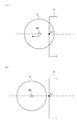
図7は、本実施形態のメニュー画像の構成例を示す図である。
図7に示すように、メニュー画像は、中心点M0を中心とする円周上に選択項目が配置されている。図示の例では、選択項目として処理の内容を示すアイコンが6個表示されている。なお、メニュー画像の構成は、中心点M0を中心とする円周上に選択項目が配置されていれば良く、図7に示すものに限定されない。すなわち、選択項目の数は6個に限定されない。また、各選択項目に対してアイコンを表示するのではなく、処理の内容を示すテキスト(デジタルフォントや図案化された文字など)を表示しても良い。さらに、アイコンとテキストを組み合わせて表示しても良い。
Next, the configuration of the menu image will be described.
FIG. 7 is a diagram illustrating a configuration example of a menu image according to the present embodiment.
As shown in FIG. 7, in the menu image, selection items are arranged on a circumference centered on the center point M0. In the illustrated example, six icons indicating the contents of processing are displayed as selection items. The configuration of the menu image is not limited to that shown in FIG. 7 as long as the selection items are arranged on the circumference centered on the center point M0. That is, the number of selection items is not limited to six. Further, instead of displaying an icon for each selection item, text indicating the contents of processing (digital font, designed characters, etc.) may be displayed. Furthermore, icons and text may be displayed in combination.
図8(a)(b)および図9は、アイコンとテキストを組み合わせたメニュー画像の例を示す図である。図8(a)に示す例では、各アイコンの外側に、中心点M0の方向を上にして横書きでテキストが記載されている。図8(b)に示す例では、各アイコンの外側に、中心点M0の方向を上にして縦書きでテキストが記載されている。図9に示す例では、各アイコンの外側に、一定の方向(図中の矢印方向)を上にして横書きでテキストが記載されている。 8A, 8B, and 9 are diagrams showing examples of menu images in which icons and text are combined. In the example shown in FIG. 8A, text is written in horizontal writing outside the icons with the direction of the center point M0 facing up. In the example shown in FIG. 8B, text is written outside the icons in vertical writing with the direction of the center point M0 facing up. In the example shown in FIG. 9, text is written in horizontal writing on the outside of each icon with a certain direction (the arrow direction in the figure) facing up.
一定の方向を上向きにしてテキストを表示するには、画面に対してどの位置にユーザが存在するかを識別する必要がある。具体的な実現手段としては、次のようなものが考えられる。IDの無線通信を行うための送信機と受信機とを用意し、画面の周囲に所定の間隔で受信機を配置すると共に、どの受信機が送信機からのIDを受信したかを判断する計算機をテーブル型表示装置10に備える。そして、ユーザが送信機を所持する。そして、例えばIDを受信した受信機の位置を下とし、画面の中心方向を上として、テキストの表示の向きを制御する。 In order to display text with a certain direction facing upward, it is necessary to identify the position where the user exists with respect to the screen. The following can be considered as specific implementation means. A computer that prepares a transmitter and a receiver for wireless communication of ID, arranges the receiver at predetermined intervals around the screen, and determines which receiver has received the ID from the transmitter Is provided in the table type display device 10. And a user possesses a transmitter. Then, for example, the direction of text display is controlled with the position of the receiver receiving the ID as the bottom and the center direction of the screen as the top.
図7〜9に示したメニュー画像において、各アイコンおよびテキストは、ボタンオブジェクトとなっている。したがって、ユーザが画面に表示されたメニュー画像のうち所望のアイコン(またはテキスト)を指でタッチすることにより項目が選択されると、そのアイコン(またはテキスト)に関連付けられた処理が実行される。 In the menu images shown in FIGS. 7 to 9, each icon and text is a button object. Therefore, when an item is selected by touching a desired icon (or text) with a finger in the menu image displayed on the screen, processing associated with the icon (or text) is executed.
ところで、メニューの選択項目は、階層的に設定される場合がある。この場合、選択された項目に、その項目に関連付けられた1段下の階層の選択項目がある場合には、その階層(選択された項目の1段下の階層)の選択項目が表示される。以下、本実施形態における多階層のメニューの表示方法の例を説明する。 Incidentally, menu selection items may be set hierarchically. In this case, if the selected item includes a selection item at the level one level lower than that associated with the item, the selection item at that level (the level one level below the selected item) is displayed. . Hereinafter, an example of a method for displaying a multi-level menu in the present embodiment will be described.
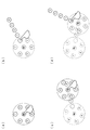
図10は、多階層のメニューの第1の表示方法を示す図である。
この表示方法では、メニューの所定の項目が選択され、その項目の下階層に選択項目がある場合、選択された項目を新たな中心点として下階層の選択項目を円形に配列したメニューが表示される。下階層の選択項目が表示された際には、上階層の選択項目は淡色やモノクロームで表示することにより、現在選択可能な階層ではないことを表現する。なお、図10において、個々の選択項目は丸印(○)で示されている。
FIG. 10 is a diagram illustrating a first display method of a multi-level menu.
In this display method, when a predetermined item in the menu is selected and there is a selection item below that item, a menu is displayed in which the selection items in the lower layer are arranged in a circle with the selected item as the new center point. The When the selection item of the lower layer is displayed, the selection item of the upper layer is displayed in light color or monochrome to express that it is not a currently selectable layer. In FIG. 10, each selection item is indicated by a circle (◯).
図10を参照すると、図10(a)は、第1階層(最も上位の階層)のメニューが表示された状態を示す。指でタッチされた位置を中心点として選択項目が円形に配列されている。図10(b)は、第1階層のメニューから選択項目2が選択され、第2階層(第1階層の選択項目2に関連付けられた1段下の階層)の選択項目がメニューとして表示された状態を示す。第1階層の選択項目2の位置が新たな中心点となって、第2階層の選択項目が円形に配列されている。図10(c)は、第2階層のメニューから選択項目4が選択され、第3階層(第2階層の選択項目4に関連付けられた、さらに1段下の階層)の選択項目がメニューとして表示された状態を示す。第2階層の選択項目4の位置が新たな中心点となって、第3階層の選択項目が円形に配列されている。
Referring to FIG. 10, FIG. 10 (a) shows a state in which the menu of the first layer (the highest layer) is displayed. The selection items are arranged in a circle with the position touched by the finger as the center point. In FIG. 10B, the
図11は、多階層のメニューの第2の表示方法を示す図である。
この表示方法では、メニューの所定の項目が選択され、その項目の下階層に選択項目がある場合、選択された項目を起点として直線的に下階層の選択項目を配列したメニューが表示される。下階層の選択項目が表示された際には、上階層の選択項目は淡色やモノクロームで表示することにより、現在選択可能な階層ではないことを表現する。なお、図11において、個々の選択項目は丸印(○)で示されている。
FIG. 11 is a diagram illustrating a second display method of a multi-level menu.
In this display method, when a predetermined item of the menu is selected and there is a selection item in the lower layer of the item, a menu in which the selection items in the lower layer are arranged linearly starting from the selected item is displayed. When the selection item of the lower layer is displayed, the selection item of the upper layer is displayed in light color or monochrome to express that it is not a currently selectable layer. In FIG. 11, individual selection items are indicated by circles (◯).
図11を参照すると、図11(a)は、図10(a)と同様に、第1階層のメニューが表示された状態を示す。図11(b)は、第1階層のメニューから選択項目2が選択され、第2階層の選択項目がメニューとして表示された状態を示す。第1階層の選択項目2が起点となって、第2階層の選択項目が、第1階層のメニューの中心点から選択項目2へ向かう方向に沿って(すなわち円の外側へ向かって)直線的に配列されている。図11(c)は、第2階層のメニューから選択項目3が選択され、第3階層の選択項目がメニューとして表示された状態を示す。第2階層の選択項目3が起点となって、第3階層の選択項目が、第2階層のメニューが伸びる方向(起点から末端へ向かう方向)に直交する方向に沿って直線的に配列されている。図11(d)は、第3階層のメニューから選択項目2が選択され、第4階層(第3階層の選択項目2に関連付けられた、さらに1段下の階層)の選択項目がメニューとして表示された状態を示す。第3階層の選択項目2が起点となって、第4階層の選択項目が、第3階層のメニューが伸びる方向に直交する方向に沿って直線的に配列されている。
Referring to FIG. 11, FIG. 11 (a) shows a state in which the first layer menu is displayed, as in FIG. 10 (a). FIG. 11B shows a state in which the
ここで、図11(c)に示した第3階層のメニューは、第2階層のメニューが伸びる方向に対して左方へ伸びている。また、第4階層のメニューは、第3階層のメニューが伸びる方向に対して右方へ伸びている。各階層のメニューが伸びる方向は、図示の例に限定されるものではないが、図示のように左方と右方へ交互に伸びていくことにより、全体としては第1階層の中心手から次第に遠ざかる方向へ伸びることとなる。そのため、第1階層から遠い(深い)階層へ進んでいることが直感的に把握しやすいと考えられる。 Here, the menu of the third hierarchy shown in FIG. 11C extends leftward with respect to the direction in which the menu of the second hierarchy extends. Further, the menu of the fourth layer extends rightward with respect to the direction in which the menu of the third layer extends. The direction in which the menu of each layer extends is not limited to the example shown in the figure, but by extending alternately to the left and right as shown in the figure, the whole menu gradually increases from the center of the first layer. It will extend in the direction of going away. For this reason, it is considered that it is easy to intuitively understand that the user is moving from the first layer to a far (deep) layer.
また、上述した第1の表示方法と第2の表示方法とを組み合わせて用いても良い。
図12は、第1の表示方法と第2の表示方法とを交互に用いた様子を示す図である。
図12を参照すると、図12(a)は、図10(a)と同様に、第1階層のメニューが表示された状態を示す。図12(b)は、第1階層のメニューから選択項目2が選択され、第2階層の選択項目がメニューとして表示された状態を示す。図11(b)に示した第2の表示方法と同様に、第1階層の選択項目2が起点となって、第2階層の選択項目が、第1階層のメニューの中心点から選択項目2へ向かう方向に沿って直線的に配列されている。図12(c)は、第2階層のメニューから選択項目3が選択され、第3階層の選択項目がメニューとして表示された状態を示す。第2階層の選択項目3の位置が新たな中心点となって、第3階層の選択項目が円形に配列されている。図12(d)は、第3階層のメニューから選択項目6が選択され、第4階層の選択項目がメニューとして表示された状態を示す。第4階層の選択項目が、第3階層のメニューの中心点から選択項目6へ向かう方向に沿って直線的に配列されている。
Further, the above-described first display method and second display method may be used in combination.
FIG. 12 is a diagram illustrating a state in which the first display method and the second display method are alternately used.
Referring to FIG. 12, FIG. 12 (a) shows a state in which the first layer menu is displayed, as in FIG. 10 (a). FIG. 12B shows a state in which the
図13は、多階層のメニューの第3の表示方法を示す図である。
この表示方法では、メニューの所定の項目が選択され、その項目の下階層に選択項目がある場合、表示中のメニュー画像の外側に下階層の選択項目を円形に配列したメニューが表示される。下階層の選択項目が表示された際には、上階層の選択項目は淡色やモノクロームで表示することにより、現在選択可能な階層ではないことを表現する。なお、図13において、個々の選択項目は丸印(○)で示されている。
FIG. 13 is a diagram illustrating a third method for displaying a multi-level menu.
In this display method, when a predetermined item of a menu is selected and there is a selection item below the item, a menu in which the selection items of the lower layer are arranged in a circle outside the currently displayed menu image is displayed. When the selection item of the lower layer is displayed, the selection item of the upper layer is displayed in light color or monochrome to express that it is not a currently selectable layer. In FIG. 13, each selection item is indicated by a circle (◯).
図13を参照すると、図13(a)は図10(a)と同様に、第1階層のメニューが表示された状態を示す。図13(b)は、第1階層のメニューから選択項目2が選択され、第2階層の選択項目がメニューとして表示された状態を示す。第1階層のメニュー画像の外側の円周上に、第2階層の選択項目が配列されている。図13(c)は、第2階層のメニューから選択項目5が選択され、第3階層の選択項目がメニューとして表示された状態を示す。第2階層のメニュー画像のさらに外側の円周上に、第3階層の選択項目が配列されている。各階層の選択項目は、円周上に等間隔で配置される。また、図13(d)に示すように、1段上の階層で選択された項目の近くに偏って配置されるようにしても良い。
Referring to FIG. 13, FIG. 13 (a) shows a state in which the first layer menu is displayed, as in FIG. 10 (a). FIG. 13B shows a state in which the
ところで、本実施形態では、各階層のメニュー画像を、階層ごとに一体の画像として生成しても良いし、各階層において個別に生成された選択項目ごとの画像を組み合わせて生成しても良い。どちらを採用するかは、後述する表示制御部123によるメニュー画像の回転制御の方法によるので、以下の回転制御の方法の説明において併せて説明する。
By the way, in this embodiment, the menu image of each hierarchy may be produced | generated as an integrated image for every hierarchy, and you may produce | generate combining the image for every selection item produced | generated separately in each hierarchy. Which one is adopted depends on the method of rotation control of the menu image by the
次に、メニュー画像の回転制御の方法について説明する。
上述したように、選択項目を円形配列したメニュー画像では、中心点よりも手前側(ユーザ側)に位置する選択項目に比べて、中心点に対してユーザとは反対側に位置する選択項目は遠くにある分だけ操作しにくい。特に多階層表示を行う場合は、図10〜13に示したいずれの表示方法を採用しても、中心点に対してユーザとは反対側に位置する選択項目の下階層のメニュー画像はユーザから遠ざかる方向に表示されるため、操作しにくいものとなる。そこで、一定時間ごとにどの選択項目も手前側に来るように、円形配列された選択項目の位置を中心点の周りに回転移動させる。
Next, a menu image rotation control method will be described.
As described above, in the menu image in which the selection items are arranged in a circle, the selection items located on the opposite side to the user with respect to the center point are compared to the selection items located on the near side (user side) from the center point. It is difficult to operate as much as it is far away. In particular, when performing multi-level display, regardless of which display method shown in FIGS. 10 to 13 is adopted, the menu image in the lower level of the selection item located on the opposite side of the user from the center point is Since it is displayed in a direction away from it, it is difficult to operate. Therefore, the position of the circularly arranged selection items is rotated around the center point so that every selection item comes to the near side at regular intervals.
なお、メニューの多階層表示がなされた場合は、下階層が表示されたまま上階層が回転すると、下方の(深い)階層のメニュー画像ほど位置が大きく動いてしまうため、操作性に支障を来すと考えられる。したがって、下階層が表示された場合は、最後に表示された階層よりも上位の階層のメニュー画像の回転を停止させる。
また、メニュー画像を回転させるのは、第1階層のメニュー画像や図10に示した表示方法による各階層のメニュー画像のように選択項目が円形配列されるメニュー画像に対してのみである。図11に示した表示方法による第2階層以下のメニュー画像のように直線配列されるメニュー画像に対しては回転制御を行わない。
If the menu is displayed in multiple layers, if the upper layer is rotated while the lower layer is displayed, the menu image in the lower (deep) layer will move more greatly, which hinders operability. It is considered. Therefore, when the lower hierarchy is displayed, the rotation of the menu image in the higher hierarchy than the last displayed hierarchy is stopped.
Also, rotating the menu image, selection items as menu image of each hierarchy by the display method shown in the menu image and FIG. 10 of the first layer is only for menu image to be circular arrangement. Not performed rotation control for the menu images are linearly arranged as the second layer following menu image by the display method shown in FIG. 11.
画面上に表示されたメニュー画像を回転させる方法として、本実施形態では、メニュー画像自体を回転させる方法と、メニュー画像を構成する各選択項目(アイコン等)の位置を動的に変化させる方法とを説明する。前者では、メニュー画像全体を1つの画像として扱うため、各階層のメニュー画像は、階層ごとに一体の画像として生成される。後者では、選択項目ごとに表示位置を制御することとなるため、メニュー画像は、各階層において個別に生成された選択項目ごとの画像を組み合わせて生成される。 As a method of rotating the menu image displayed on the screen, in the present embodiment, a method of rotating the menu image itself, a method of dynamically changing the position of each selection item (icon or the like) constituting the menu image, Will be explained. In the former, since the entire menu image is handled as one image, the menu image of each layer is generated as an integrated image for each layer. In the latter case, since the display position is controlled for each selection item, the menu image is generated by combining images for each selection item generated individually in each layer.
まず、メニュー画像自体を回転させる方法について説明する。
この場合、メニュー画像は、階層ごとの動画ファイルとして生成される。例えば米国アドビシステムズ社の「Flash」のようなソフトウェアを用いることにより、円形配置された各選択項目(アイコン等)に個別にボタン機能を持たせた動画ファイルとしてメニュー画像を生成することができる。この場合、例えば、メニュー画像の動画ファイルは、画像生成部122において生成される。そして、表示制御部123は、画像生成部122により生成された動画ファイルを再生することにより、メニュー画像の回転制御を実現する。
First, a method for rotating the menu image itself will be described.
In this case, the menu image is generated as a moving image file for each layer. For example, by using software such as “Flash” of Adobe Systems Incorporated, a menu image can be generated as a moving image file in which each selection item (icon or the like) arranged in a circle is individually provided with a button function. In this case, for example, the moving image file of the menu image is generated in the
また、メニュー画像を動画ファイルとするのではなく、選択項目の位置が少しずつ異なる複数のメニュー画像の静止画を生成しておき、この静止画を順次切り替えて表示することによっても、あたかもメニュー画像が回転しているかのような表現が実現される。この場合、例えば、画像生成部122が複数のメニュー画像の静止画を生成し、表示制御部123が各静止画の表示の切り替えを制御する。
Also, instead of creating a menu image as a moving image file, it is possible to generate a plurality of menu image still images with slightly different selection items, and display the menu images by switching the still images in sequence. The expression as if is rotating is realized. In this case, for example, the
次に、メニュー画像を構成する各選択項目の位置を動的に変化させる方法について説明する。
この場合、各選択項目(アイコン等)は、それぞれ独立に生成され、メニュー画像の中心点に対する相対位置によって配置位置が特定される。例えば、メニュー画像が6個の選択項目を持ち、各選択項目がメニュー画像の中心点を中心として半径iの円周上に等間隔に配列される場合を考える。この場合、画面上における中心点の座標を(x,y)とすれば、6個の選択項目の配置位置は、例えば、(x,y+i)、(x+√3i/2,y+i/2)、(x+√3i/2,y−i/2)、(x,y−i)、(x−√3i/2,y−i/2)、(x−√3i/2,y+i/2)の6箇所となる。そして、各選択項目をこれらの位置に配置し、各位置に表示される選択項目を順次切り替える。このようにすれば、各選択項目がこれらの配置位置を順次移動するように表示されるため、コマ送り的な動きではあるが、各選択項目が中心点の周りを回転(移動)しているかのような表現が実現される。
Next, a method for dynamically changing the position of each selection item constituting the menu image will be described.
In this case, each selection item (icon or the like) is generated independently, and the arrangement position is specified by the relative position with respect to the center point of the menu image. For example, consider a case where a menu image has six selection items, and each selection item is arranged at equal intervals on the circumference of a radius i with the center point of the menu image as the center. In this case, if the coordinates of the center point on the screen are (x, y), the arrangement positions of the six selection items are, for example, (x, y + i), (x + √3i / 2, y + i / 2), (X + √3i / 2, y−i / 2), (x, y−i), (x−√3i / 2, y−i / 2), (x−√3i / 2, y + i / 2) There will be 6 places. And each selection item is arrange | positioned in these positions, and the selection item displayed at each position is switched sequentially. In this way, each selection item is displayed so as to move sequentially between these arrangement positions, so that each selection item is rotating (moving) around the center point although it is a frame-by-frame movement. Such an expression is realized.
さらに、上記の6箇所に加えて、(x+i/2,y+√3i/2)、(x+i,y)、(x+i/2,y−√3i/2)、(x−i/2,y−√3i/2)、(x−i,y)、(x−i/2,y+√3i/2)の6箇所を選択項目の配置位置として定義しておく。そして、最初の6箇所のセットと次の6箇所のセットとを切り換えながら、各位置に表示される選択項目を順次切り替える。これにより、より滑らかな回転が表現される。
これらの手法を取る場合は、例えば、画像生成部122が各選択項目の画像やテキストを生成し、かつ各選択項目の配置位置を選択項目の個数に応じて設定し、表示制御部123が各選択項目の表示の切り替えを制御する。
Furthermore, in addition to the above six locations, (x + i / 2, y + √3i / 2), (x + i, y), (x + i / 2, y−√3i / 2), (x−i / 2, y− Six locations (√3i / 2), (x−i, y), and (x−i / 2, y + √3i / 2) are defined as arrangement positions of selection items. Then, while switching between the first six sets and the next six sets, the selection items displayed at each position are sequentially switched. Thereby, smoother rotation is expressed.
When taking these methods, for example, the
なお、これらのメニュー画像の表示制御方法は例示に過ぎず、上記の具体的な手法のみに限定されるものではない。また、選択項目の表示にテキストを用いる場合、メニュー画像自体を回転させる方法では、テキスト自体も回転してしまう。そのため、図9に示したようにメニュー画像において一定の方向を上にしてテキストを記載する場合は、メニュー画像を構成する各選択項目の位置を動的に変化させる方法が取られる。 Note that these menu image display control methods are merely examples, and are not limited to the specific methods described above. In addition, when text is used for displaying the selection item, the method of rotating the menu image itself rotates the text itself. Therefore, as shown in FIG. 9, when a text is described with a certain direction upward in the menu image, a method of dynamically changing the position of each selection item constituting the menu image is taken.
上述したメニュー画像の回転制御は、例えば、メニュー画像の表示制御により画面上に表示されてからメニュー画像の消去制御により画面上から消去されるまでの間、一定の回転速度で回転するように行っても良い。また、表示された当初から次第に遅く(あるいは速く)なるように回転速度を変更させても良い。さらに、メニュー画像に対するユーザによる操作(例えばいずれかの選択項目にタッチしてドラッグするような操作)に応じて、あたかも手動で回転するかのように回転制御を行っても良い。 The above-described rotation control of the menu image is performed, for example, so that the menu image rotates at a constant rotation speed from when it is displayed on the screen by the display control of the menu image until it is deleted from the screen by the deletion control of the menu image. May be. Further, the rotational speed may be changed so as to become gradually (or faster) from the beginning of the display. Furthermore, rotation control may be performed as if it is manually rotated in response to a user operation on the menu image (for example, an operation of touching and dragging any selection item).
なお、本実施形態では、天板11に設けられたタッチパネルに対する指でのタッチをタッチパネルが検知することでユーザ操作が検出されるものとして説明したが、指以外に、例えばペンデバイス等の特殊デバイスによるタッチをタッチパネルが検知してユーザ操作が検出されるようにしても良い。さらに、タッチパネルへのタッチだけでなく、マウス等の他のポインティングデバイスを用いた操作を受け付けるようにしても良い。
In the present embodiment, the user operation is detected when the touch panel detects a touch on the touch panel provided on the
最後に、本実施形態のテーブル型表示装置10における演算ユニットをコンピュータ90にて実現するものとして、このコンピュータ90のハードウェア構成例について説明する。
図14は、コンピュータ90のハードウェア構成を示した図である。
図示するように、コンピュータ90は、演算手段であるCPU(Central Processing Unit)91と、記憶手段であるメインメモリ92及び磁気ディスク装置(HDD:Hard Disk Drive)93とを備える。ここで、CPU91は、OS(Operating System)やアプリケーション等の各種ソフトウェアを実行し、各種の機能を実現する。また、メインメモリ92は、各種ソフトウェアやその実行に用いるデータ等を記憶する記憶領域であり、磁気ディスク装置93は、各種ソフトウェアに対する入力データや各種ソフトウェアからの出力データ等を記憶する記憶領域である。
さらに、コンピュータ90は、外部との通信を行うための通信I/F94と、ビデオメモリやディスプレイ等からなる表示機構95と、キーボードやマウス等の入力デバイス96とを備える。
Finally, a hardware configuration example of the computer 90 will be described assuming that the arithmetic unit in the table type display device 10 of the present embodiment is realized by the computer 90.
FIG. 14 is a diagram illustrating a hardware configuration of the computer 90.
As shown in the figure, the computer 90 includes a CPU (Central Processing Unit) 91 as a calculation means, a
Further, the computer 90 includes a communication I /
本実施形態のテーブル型表示装置10の演算ユニットが図14に示したコンピュータ90で実現される場合、図3に示した操作検出部110、メニュー表示部120およびコマンド出力部130は、磁気ディスク装置93からメインメモリ92に読み込まれたプログラム(ソフトウェア)をCPU91が実行することにより実現される。また、画像位置記憶部140は、メインメモリ92や磁気ディスク装置93等の記憶手段により実現される。なお、本実施形態を実現するプログラムは、通信手段により提供することはもちろん、CD−ROM等の記録媒体に格納して提供することも可能である。
When the arithmetic unit of the table type display device 10 of the present embodiment is realized by the computer 90 shown in FIG. 14, the
10…テーブル型表示装置、11…天板、13…投影ユニット、15…プロジェクタ、110…操作検出部、120…メニュー表示部、121…表示位置決定部、122…画像生成部、123…表示制御部、130…コマンド出力部 DESCRIPTION OF SYMBOLS 10 ... Table type display apparatus, 11 ... Top plate, 13 ... Projection unit, 15 ... Projector, 110 ... Operation detection part, 120 ... Menu display part, 121 ... Display position determination part, 122 ... Image generation part, 123 ... Display control Part, 130 ... command output part
Claims (14)
ディスプレイ装置の画面上に前記メニュー画像を表示させ、当該メニュー画像における前記選択項目の位置を動的に変化させる制御手段と、
前記ディスプレイ装置の画面に表示されたオブジェクト画像の位置を認識し、当該オブジェクト画像と前記メニュー画像とが重ならないように当該メニュー画像の表示位置を決定する決定手段とを備え、
前記制御手段は、前記決定手段により決定された位置に前記メニュー画像を表示させることを特徴とする表示装置。 Generating means for generating a menu image in which menu selection items are geometrically arranged;
Control means for displaying the menu image on a screen of a display device and dynamically changing the position of the selection item in the menu image ;
Recognizing the position of the object image displayed on the screen of the display device, and determining means for determining the display position of the menu image so that the object image and the menu image do not overlap,
Wherein, the display device according to claim Rukoto to display the menu image on the position determined by said determining means.
前記制御手段は、前記メニュー画像の動画ファイルを前記ディスプレイ装置の画面上で再生させることにより、前記選択項目の位置を変化させることを特徴とする請求項1に記載の表示装置。 The generation unit generates the menu image as a moving image file in which the selection item rotates on a predetermined circumference,
The display device according to claim 1, wherein the control unit changes the position of the selection item by reproducing a moving image file of the menu image on a screen of the display device.
前記制御手段は、複数の前記メニュー画像を切り換えながら前記ディスプレイ装置の画面に表示させることにより、前記選択項目の位置を変化させることを特徴とする請求項1に記載の表示装置。 The generation means generates a plurality of the menu images in which the selection items are arranged at different positions in a certain area,
The display device according to claim 1, wherein the control unit changes the position of the selection item by displaying the menu image on a screen of the display device while switching the plurality of menu images.
前記制御手段は、前記選択項目と同数またはそれ以上の数の当該選択項目の配置位置を設定し、各配置位置に表示される選択項目を順次切り替えることにより、当該選択項目の位置を変化させることを特徴とする請求項1に記載の表示装置。 The generating means generates the menu image by combining images for each of the selection items generated individually,
The control means sets an arrangement position of the selection items of the same number or more as the selection items, and changes the position of the selection items by sequentially switching the selection items displayed at the respective arrangement positions. The display device according to claim 1.
前記制御手段は、表示されているメニュー画像に含まれる選択項目のうちで下位の階層に関連付けられた選択項目が選択された場合に、当該下位の階層のメニュー画像を前記ディスプレイ装置の画面に表示させることを特徴とする請求項1に記載の表示装置。 The generation means generates the menu image individually for each hierarchy of menus set hierarchically,
The control means displays the menu image of the lower hierarchy on the screen of the display device when a selection item associated with the lower hierarchy is selected from the selection items included in the displayed menu image. The display device according to claim 1, wherein:
前記制御手段は、所定の前記選択項目が選択された場合に、当該選択項目を前記円周の中心点として、当該選択項目に関連付けられた階層の前記メニュー画像を表示することを特徴とする請求項6に記載の表示装置。 The generating means generates a menu image in which the selection items in the hierarchy are arranged on a circumference for each hierarchy,
The control means, when a predetermined selection item is selected, displays the menu image of a hierarchy associated with the selection item with the selection item as a center point of the circumference. Item 7. The display device according to Item 6.
前記メニュー画像において円周上に配列された前記選択項目の位置を当該円周の中心点の周りに回転移動させ、Rotating the position of the selection items arranged on the circumference in the menu image around the center point of the circumference;
新たな階層の前記メニュー画像が表示された場合は、当該新たな階層より上位の階層の前記メニュー画像についての前記選択項目の回転移動を停止させるWhen the menu image of a new hierarchy is displayed, the rotational movement of the selection item for the menu image of a hierarchy higher than the new hierarchy is stopped.
ことを特徴とする請求項7に記載の表示装置。The display device according to claim 7.
前記制御手段は、所定の前記選択項目が選択された場合に、当該選択項目を基点として、当該選択項目に関連付けられた階層の前記メニュー画像を、直線的に配列された前記選択項目が一定の方向に伸びるように表示することを特徴とする請求項6に記載の表示装置。 The generating means generates a menu image in which the selection items are linearly arranged for the second and lower layers.
When the predetermined selection item is selected, the control means uses the selection item as a base point, the menu image of the hierarchy associated with the selection item, the selection items arranged linearly are fixed. The display device according to claim 6, wherein the display is performed so as to extend in a direction.
新たな階層の前記選択項目についての前記一定の方向が最後に表示された階層の前記選択項目についての前記一定の方向に対し左方または右方に伸びる方向であるように、当該新たな階層の前記メニュー画像を表示し、The new direction of the new hierarchy is such that the constant direction for the selection item of the new hierarchy is a direction that extends to the left or right with respect to the constant direction for the selection item of the last displayed hierarchy. Display the menu image,
最後に表示された階層における前記一定の方向が当該最後に表示された階層の直前の階層における前記一定の方向に対し左方である場合に、新たな階層における前記一定の方向が当該最後に表示された階層における当該一定の方向に対し右方であるように、If the certain direction in the last displayed hierarchy is to the left of the certain direction in the hierarchy immediately before the last displayed hierarchy, the certain direction in the new hierarchy is displayed last. To the right of the given direction in the given hierarchy,
最後に表示された階層における前記一定の方向が当該最後に表示された階層の直前の階層における前記一定の方向に対し右方である場合に、新たな階層における前記一定の方向が当該最後に表示された階層における当該一定の方向に対し左方であるように、If the certain direction in the last displayed hierarchy is to the right of the certain direction in the hierarchy immediately before the last displayed hierarchy, the certain direction in the new hierarchy is displayed last. To the left of the given direction in the given hierarchy,
当該新たな階層の前記メニュー画像を表示することを特徴とする請求項9に記載の表示装置。The display device according to claim 9, wherein the menu image of the new hierarchy is displayed.
前記制御手段は、The control means includes
前記第1のメニュー画像に含まれる所定の前記選択項目が選択された場合に、当該選択項目を基点として、当該選択項目に関連付けられた下位の階層の前記第2のメニュー画像を、当該下位の階層の直線的に配列された前記選択項目が一定の方向に伸びるように表示し、When the predetermined selection item included in the first menu image is selected, the second menu image in the lower hierarchy associated with the selection item is used as the lower level, with the selection item as a base point. Display the selection items arranged in a straight line of the hierarchy so as to extend in a certain direction,
前記第2のメニュー画像に含まれる所定の前記選択項目が選択された場合に、当該選択項目を前記円周の中心点として、当該選択項目に関連付けられた下位の階層の前記第1のメニュー画像を表示するWhen the predetermined selection item included in the second menu image is selected, the first menu image in the lower hierarchy associated with the selection item with the selection item as the center point of the circumference Display
ことを特徴とする請求項6に記載の表示装置。The display device according to claim 6.
前記制御手段は、所定の前記選択項目が選択された場合に、当該選択項目に関連付けられた階層の前記メニュー画像を、当該選択項目が含まれる階層のメニュー画像の外側に表示することを特徴とする請求項6に記載の表示装置。 The generation unit generates a menu image in which selection items of the hierarchy are arranged on a circumference corresponding to the outer periphery of the menu image of the hierarchy one level higher than the hierarchy in the second stage,
When the predetermined selection item is selected, the control means displays the menu image of the hierarchy associated with the selection item outside the menu image of the hierarchy including the selection item. The display device according to claim 6.
前記制御手段は、ディスプレイ装置の画面であって複数のユーザが取り囲んで見ることができる画面上に当該複数のユーザが複数の方向から前記選択項目のそれぞれを操作可能であるように前記メニュー画像を表示させ、予め定めた時間ごとに当該メニュー画像における前記選択項目のそれぞれが当該複数のユーザのいずれにとっても前記円周の中心点に対して手前側に来るように当該選択項目の位置を動的に変化させることを特徴とする請求項1に記載の表示装置。The control means displays the menu image so that the plurality of users can operate each of the selection items from a plurality of directions on a screen of a display device that can be surrounded and viewed by the plurality of users. The position of the selection item is dynamically displayed so that each of the selection items in the menu image comes closer to the center point of the circumference for each of the plurality of users at predetermined time intervals. The display device according to claim 1, wherein the display device is changed.
メニューの選択項目を円周上に配列したメニュー画像を生成する機能と、
ディスプレイ装置の画面上に前記メニュー画像を表示させ、当該メニュー画像における前記選択項目の前記円周上における位置を動的に変化させる制御機能と、
前記ディスプレイ装置の画面に表示されたオブジェクト画像の位置を認識し、当該オブジェクト画像と前記メニュー画像とが重ならないように当該メニュー画像の表示位置を決定する機能とを実現させ、
前記制御機能は、前記決定する機能により決定された位置に前記メニュー画像を表示させることを特徴とするプログラム。 On the computer,
A function for generating a menu image in which menu selection items are arranged on the circumference;
A control function for displaying the menu image on a screen of a display device and dynamically changing a position on the circumference of the selection item in the menu image ;
Realizing the function of recognizing the position of the object image displayed on the screen of the display device and determining the display position of the menu image so that the object image and the menu image do not overlap ,
The control function program characterized Rukoto to display the menu image on the position determined by the function that said determining.
Priority Applications (2)
| Application Number | Priority Date | Filing Date | Title |
|---|---|---|---|
| JP2007090364A JP4899991B2 (en) | 2007-03-30 | 2007-03-30 | Display device and program |
| US11/937,160 US8286096B2 (en) | 2007-03-30 | 2007-11-08 | Display apparatus and computer readable medium |
Applications Claiming Priority (1)
| Application Number | Priority Date | Filing Date | Title |
|---|---|---|---|
| JP2007090364A JP4899991B2 (en) | 2007-03-30 | 2007-03-30 | Display device and program |
Publications (2)
| Publication Number | Publication Date |
|---|---|
| JP2008250620A JP2008250620A (en) | 2008-10-16 |
| JP4899991B2 true JP4899991B2 (en) | 2012-03-21 |
Family
ID=39796478
Family Applications (1)
| Application Number | Title | Priority Date | Filing Date |
|---|---|---|---|
| JP2007090364A Active JP4899991B2 (en) | 2007-03-30 | 2007-03-30 | Display device and program |
Country Status (2)
| Country | Link |
|---|---|
| US (1) | US8286096B2 (en) |
| JP (1) | JP4899991B2 (en) |
Families Citing this family (62)
| Publication number | Priority date | Publication date | Assignee | Title |
|---|---|---|---|---|
| US8615720B2 (en) * | 2007-11-28 | 2013-12-24 | Blackberry Limited | Handheld electronic device and associated method employing a graphical user interface to output on a display virtually stacked groups of selectable objects |
| US8295879B2 (en) * | 2008-05-30 | 2012-10-23 | Motorola Mobility Llc | Devices and methods for initiating functions based on movement characteristics relative to a reference |
| EP2350786A4 (en) * | 2008-10-15 | 2012-06-13 | Inputive Corp | System and method for seamlessly integrated navigation of applications |
| US8321802B2 (en) | 2008-11-13 | 2012-11-27 | Qualcomm Incorporated | Method and system for context dependent pop-up menus |
| US9002416B2 (en) | 2008-12-22 | 2015-04-07 | Google Technology Holdings LLC | Wireless communication device responsive to orientation and movement |
| KR20100076794A (en) * | 2008-12-26 | 2010-07-06 | 삼성전자주식회사 | Apparatus and method for digital picturing image |
| US9383897B2 (en) | 2009-01-29 | 2016-07-05 | International Business Machines Corporation | Spiraling radial menus in computer systems |
| US9141275B2 (en) * | 2009-02-17 | 2015-09-22 | Hewlett-Packard Development Company, L.P. | Rendering object icons associated with a first object icon upon detecting fingers moving apart |
| CN102439544A (en) * | 2009-03-20 | 2012-05-02 | 谷歌股份有限公司 | Interaction with ime computing device |
| KR20100134948A (en) * | 2009-06-16 | 2010-12-24 | 삼성전자주식회사 | Method for displaying menu list in touch screen based device |
| KR101686913B1 (en) * | 2009-08-13 | 2016-12-16 | 삼성전자주식회사 | Apparatus and method for providing of event service in a electronic machine |
| JP2011076340A (en) * | 2009-09-30 | 2011-04-14 | Ntt Docomo Inc | Information processing device and program |
| US20110119589A1 (en) * | 2009-11-19 | 2011-05-19 | Motorola, Inc. | Navigable User Interface for Electronic Handset |
| JP2011203823A (en) | 2010-03-24 | 2011-10-13 | Sony Corp | Image processing device, image processing method and program |
| US20110248928A1 (en) * | 2010-04-08 | 2011-10-13 | Motorola, Inc. | Device and method for gestural operation of context menus on a touch-sensitive display |
| WO2011135944A1 (en) * | 2010-04-30 | 2011-11-03 | 日本電気株式会社 | Information processing terminal and operation control method for same |
| JP5355505B2 (en) * | 2010-06-24 | 2013-11-27 | 三菱電機株式会社 | Equipment control device |
| JP5625599B2 (en) * | 2010-08-04 | 2014-11-19 | ソニー株式会社 | Information processing apparatus, information processing method, and program |
| JP5580694B2 (en) * | 2010-08-24 | 2014-08-27 | キヤノン株式会社 | Information processing apparatus, control method therefor, program, and storage medium |
| EP2490113B1 (en) * | 2011-02-15 | 2016-11-23 | Lg Electronics Inc. | Display device and method of controlling operation thereof |
| JP5977922B2 (en) * | 2011-02-24 | 2016-08-24 | セイコーエプソン株式会社 | Information processing apparatus, information processing apparatus control method, and transmissive head-mounted display apparatus |
| US20130019201A1 (en) * | 2011-07-11 | 2013-01-17 | Microsoft Corporation | Menu Configuration |
| US10001898B1 (en) | 2011-07-12 | 2018-06-19 | Domo, Inc. | Automated provisioning of relational information for a summary data visualization |
| US9202297B1 (en) | 2011-07-12 | 2015-12-01 | Domo, Inc. | Dynamic expansion of data visualizations |
| US9792017B1 (en) | 2011-07-12 | 2017-10-17 | Domo, Inc. | Automatic creation of drill paths |
| US9619139B2 (en) * | 2011-10-03 | 2017-04-11 | Kyocera Corporation | Device, method, and storage medium storing program |
| JP5894764B2 (en) * | 2011-11-01 | 2016-03-30 | シャープ株式会社 | Information processing device |
| JP5647968B2 (en) * | 2011-11-22 | 2015-01-07 | 株式会社ソニー・コンピュータエンタテインメント | Information processing apparatus and information processing method |
| CN104246677A (en) * | 2012-04-20 | 2014-12-24 | 索尼公司 | Information processing device, information processing method, and program |
| DE102012008239B4 (en) * | 2012-04-24 | 2021-05-20 | Grenzebach Maschinenbau Gmbh | Method and device for the flush transfer of large-area panels of different designs onto a transport vehicle |
| CN102799347B (en) * | 2012-06-05 | 2017-01-04 | 北京小米科技有限责任公司 | User interface interaction method and device applied to touch screen equipment and touch screen equipment |
| WO2013187872A1 (en) * | 2012-06-11 | 2013-12-19 | Intel Corporation | Techniques for select-hold-release electronic device navigation menu system |
| JP6253222B2 (en) * | 2012-07-09 | 2017-12-27 | キヤノン株式会社 | Display control apparatus, display control method, and program |
| EP2897059A4 (en) | 2012-09-13 | 2016-07-06 | Ntt Docomo Inc | User interface device, search method, and program |
| CN102981768B (en) * | 2012-12-04 | 2016-12-21 | 中兴通讯股份有限公司 | A kind of method and system realizing floated overall situation button at touch screen terminal interface |
| KR102085225B1 (en) * | 2012-12-05 | 2020-03-05 | 삼성전자주식회사 | User terminal apparatus and contol method thereof |
| JP2014153143A (en) * | 2013-02-07 | 2014-08-25 | Hioki Ee Corp | Measurement device and program |
| JP2014174931A (en) * | 2013-03-12 | 2014-09-22 | Sharp Corp | Drawing device |
| AU2014100094A4 (en) | 2013-06-26 | 2014-03-06 | Zazzle Inc. | Displaying Customization Options and Collecting Customization Specifications |
| JP6418157B2 (en) * | 2013-07-09 | 2018-11-07 | ソニー株式会社 | Information processing apparatus, information processing method, and computer program |
| JP6153007B2 (en) * | 2013-07-19 | 2017-06-28 | 株式会社コナミデジタルエンタテインメント | Operation system, operation control method, operation control program |
| JP6189680B2 (en) * | 2013-08-23 | 2017-08-30 | シャープ株式会社 | Interface device, interface method, interface program, and computer-readable recording medium storing the program |
| JP2015041356A (en) * | 2013-08-23 | 2015-03-02 | 富士通株式会社 | Electronic device and menu control program |
| KR102206053B1 (en) * | 2013-11-18 | 2021-01-21 | 삼성전자주식회사 | Apparatas and method for changing a input mode according to input method in an electronic device |
| JP6351295B2 (en) * | 2014-02-21 | 2018-07-04 | キヤノン株式会社 | Display control apparatus and display control method |
| USD772255S1 (en) * | 2014-05-12 | 2016-11-22 | The Coca-Cola Company | Display screen or portion thereof with a graphical user interface |
| USD762709S1 (en) * | 2014-05-26 | 2016-08-02 | Hon Hai Precision Industry Co., Ltd. | Display screen or portion thereof with graphical user interface |
| USD762693S1 (en) | 2014-09-03 | 2016-08-02 | Apple Inc. | Display screen or portion thereof with graphical user interface |
| USD771646S1 (en) * | 2014-09-30 | 2016-11-15 | Apple Inc. | Display screen or portion thereof with graphical user interface |
| USD765098S1 (en) | 2015-03-06 | 2016-08-30 | Apple Inc. | Display screen or portion thereof with graphical user interface |
| USD802620S1 (en) * | 2015-08-12 | 2017-11-14 | Samsung Electronics Co., Ltd. | Display screen or portion thereof with animiated graphical user interface |
| CN106775265A (en) * | 2015-11-24 | 2017-05-31 | 北京国双科技有限公司 | Show the method and device of menu |
| US20170185261A1 (en) * | 2015-12-28 | 2017-06-29 | Htc Corporation | Virtual reality device, method for virtual reality |
| EP3223130A1 (en) * | 2016-03-22 | 2017-09-27 | Continental Automotive GmbH | Method of controlling an input device for navigating a hierarchical menu |
| EP3540580A4 (en) * | 2016-11-08 | 2020-05-27 | Sony Corporation | Information processing device, information processing method, and program |
| US10417797B2 (en) * | 2016-12-22 | 2019-09-17 | Metricstream, Inc. | Graphically displaying data having complex relationships |
| CN109324846B (en) * | 2017-07-28 | 2021-11-23 | 北京小米移动软件有限公司 | Application display method and device and storage medium |
| USD915450S1 (en) * | 2017-10-31 | 2021-04-06 | M3 Accounting Services, Inc. | Display screen, or portion thereof, with a transitional graphical user interface component |
| USD832866S1 (en) * | 2017-11-20 | 2018-11-06 | Salesforce.Com, Inc. | Display screen or portion thereof with animated graphical user interface |
| JP6789206B2 (en) * | 2017-12-26 | 2020-11-25 | 株式会社ミクシィ | Screen information processing device and its control method and control program |
| JP7148817B2 (en) * | 2020-10-30 | 2022-10-06 | 株式会社ミクシィ | Screen information processing device and its control method and control program |
| JP2023005930A (en) * | 2021-06-30 | 2023-01-18 | フォルシアクラリオン・エレクトロニクス株式会社 | Control value setting apparatus and control value setting program |
Family Cites Families (28)
| Publication number | Priority date | Publication date | Assignee | Title |
|---|---|---|---|---|
| JPH06202784A (en) * | 1992-12-29 | 1994-07-22 | Casio Comput Co Ltd | Character inputting device |
| EP0622722B1 (en) * | 1993-04-30 | 2002-07-17 | Xerox Corporation | Interactive copying system |
| US5596699A (en) * | 1994-02-02 | 1997-01-21 | Driskell; Stanley W. | Linear-viewing/radial-selection graphic for menu display |
| JPH08123647A (en) * | 1994-10-25 | 1996-05-17 | Sharp Corp | Information processor |
| US5689667A (en) * | 1995-06-06 | 1997-11-18 | Silicon Graphics, Inc. | Methods and system of controlling menus with radial and linear portions |
| US5798760A (en) * | 1995-06-07 | 1998-08-25 | Vayda; Mark | Radial graphical menuing system with concentric region menuing |
| US6011542A (en) * | 1998-02-13 | 2000-01-04 | Sony Corporation | Graphical text entry wheel |
| JP3358583B2 (en) * | 1999-03-30 | 2002-12-24 | 松下電器産業株式会社 | Car navigation device and its selection screen display method |
| EP1085432B1 (en) * | 1999-09-20 | 2008-12-03 | NCR International, Inc. | Information retrieval and display |
| JP4332964B2 (en) * | 1999-12-21 | 2009-09-16 | ソニー株式会社 | Information input / output system and information input / output method |
| US7327376B2 (en) * | 2000-08-29 | 2008-02-05 | Mitsubishi Electric Research Laboratories, Inc. | Multi-user collaborative graphical user interfaces |
| US6791530B2 (en) * | 2000-08-29 | 2004-09-14 | Mitsubishi Electric Research Laboratories, Inc. | Circular graphical user interfaces |
| US7036090B1 (en) * | 2001-09-24 | 2006-04-25 | Digeo, Inc. | Concentric polygonal menus for a graphical user interface |
| JP2004259247A (en) | 2002-06-21 | 2004-09-16 | Mitsubishi Electric Research Laboratories Inc | Multi-user collaborative circular graphical user interface |
| US7663605B2 (en) * | 2003-01-08 | 2010-02-16 | Autodesk, Inc. | Biomechanical user interface elements for pen-based computers |
| US7437685B2 (en) * | 2003-03-10 | 2008-10-14 | Microsoft Corporation | Logical, safe, and more personal user interface for accessing data and launching programs or applications |
| JP3945445B2 (en) | 2003-04-21 | 2007-07-18 | ソニー株式会社 | Display method and display device |
| US7210107B2 (en) * | 2003-06-27 | 2007-04-24 | Microsoft Corporation | Menus whose geometry is bounded by two radii and an arc |
| US20050183035A1 (en) * | 2003-11-20 | 2005-08-18 | Ringel Meredith J. | Conflict resolution for graphic multi-user interface |
| US7559036B1 (en) * | 2004-03-05 | 2009-07-07 | Trading Technologies International, Inc. | System and method for displaying a constant time selection context menu interface |
| US8108890B2 (en) * | 2004-04-20 | 2012-01-31 | Green Stuart A | Localised menus |
| JP2006139615A (en) | 2004-11-12 | 2006-06-01 | Access Co Ltd | Display device, menu display program, and tab display program |
| US20060156249A1 (en) * | 2005-01-12 | 2006-07-13 | Blythe Michael M | Rotate a user interface |
| US7730425B2 (en) * | 2005-11-30 | 2010-06-01 | De Los Reyes Isabelo | Function-oriented user interface |
| US8930834B2 (en) * | 2006-03-20 | 2015-01-06 | Microsoft Corporation | Variable orientation user interface |
| US20070256029A1 (en) * | 2006-05-01 | 2007-11-01 | Rpo Pty Llimited | Systems And Methods For Interfacing A User With A Touch-Screen |
| EP1860534A1 (en) * | 2006-05-22 | 2007-11-28 | LG Electronics Inc. | Mobile terminal and menu display method thereof |
| US7552402B2 (en) * | 2006-06-22 | 2009-06-23 | Microsoft Corporation | Interface orientation using shadows |
-
2007
- 2007-03-30 JP JP2007090364A patent/JP4899991B2/en active Active
- 2007-11-08 US US11/937,160 patent/US8286096B2/en active Active
Also Published As
| Publication number | Publication date |
|---|---|
| JP2008250620A (en) | 2008-10-16 |
| US20080244454A1 (en) | 2008-10-02 |
| US8286096B2 (en) | 2012-10-09 |
Similar Documents
| Publication | Publication Date | Title |
|---|---|---|
| JP4899991B2 (en) | Display device and program | |
| JP5922598B2 (en) | Multi-touch usage, gestures and implementation | |
| US10742573B2 (en) | Method of providing message and user device supporting the same | |
| US8217905B2 (en) | Method and apparatus for touchscreen based user interface interaction | |
| TWI633461B (en) | Computer-implemented method,non-transitory computer-readable storage medium,and electronic device for manipulating user interface objects | |
| US10747391B2 (en) | Method and device for executing applications through application selection screen | |
| JP4557058B2 (en) | Information display terminal, information display method, and program | |
| US11010032B2 (en) | Navigating a hierarchical data set | |
| US20080297484A1 (en) | Method and apparatus for providing gesture information based on touchscreen and information terminal device having the apparatus | |
| US9158446B2 (en) | Method and apparatus for interfacing | |
| AU2014312481B2 (en) | Display apparatus, portable device and screen display methods thereof | |
| JP5460679B2 (en) | Information processing apparatus, information processing method, and data structure of content file | |
| KR101463540B1 (en) | Method for controlling three dimensional virtual cursor using portable device | |
| KR20160046150A (en) | Apparatus and method for drawing and solving a figure content | |
| KR20170040283A (en) | Dynamic joint dividers for application windows | |
| JP2015507783A (en) | Display device and screen mode changing method using the same | |
| JP2015508211A (en) | Method and apparatus for controlling a screen by tracking a user's head through a camera module and computer-readable recording medium thereof | |
| JP2013109668A (en) | Information processing apparatus and information processing method | |
| KR20150094967A (en) | Electro device executing at least one application and method for controlling thereof | |
| JP2019023849A (en) | Input control method, computer, and program | |
| JP5921703B2 (en) | Information display device and operation control method in information display device | |
| JP3357760B2 (en) | Character / graphic input editing device | |
| JP2002007023A (en) | Device and method for selecting menu, and computer readable recording medium with menu selection program recorded thereon | |
| KR100842089B1 (en) | Electronic device for providing 3D-UI and the same method | |
| JP7030527B2 (en) | Electronic devices, information processing methods, programs and storage media |
Legal Events
| Date | Code | Title | Description |
|---|---|---|---|
| A621 | Written request for application examination |
Free format text: JAPANESE INTERMEDIATE CODE: A621 Effective date: 20100218 |
|
| A977 | Report on retrieval |
Free format text: JAPANESE INTERMEDIATE CODE: A971007 Effective date: 20110913 |
|
| A131 | Notification of reasons for refusal |
Free format text: JAPANESE INTERMEDIATE CODE: A131 Effective date: 20110920 |
|
| A521 | Request for written amendment filed |
Free format text: JAPANESE INTERMEDIATE CODE: A523 Effective date: 20111117 |
|
| TRDD | Decision of grant or rejection written | ||
| A01 | Written decision to grant a patent or to grant a registration (utility model) |
Free format text: JAPANESE INTERMEDIATE CODE: A01 Effective date: 20111206 |
|
| A01 | Written decision to grant a patent or to grant a registration (utility model) |
Free format text: JAPANESE INTERMEDIATE CODE: A01 |
|
| A61 | First payment of annual fees (during grant procedure) |
Free format text: JAPANESE INTERMEDIATE CODE: A61 Effective date: 20111219 |
|
| R150 | Certificate of patent or registration of utility model |
Ref document number: 4899991 Country of ref document: JP Free format text: JAPANESE INTERMEDIATE CODE: R150 Free format text: JAPANESE INTERMEDIATE CODE: R150 |
|
| FPAY | Renewal fee payment (event date is renewal date of database) |
Free format text: PAYMENT UNTIL: 20150113 Year of fee payment: 3 |
|
| S533 | Written request for registration of change of name |
Free format text: JAPANESE INTERMEDIATE CODE: R313533 |
|
| R350 | Written notification of registration of transfer |
Free format text: JAPANESE INTERMEDIATE CODE: R350 |