JP4898747B2 - Inkjet printer for long web printing using phase change ink - Google Patents
Inkjet printer for long web printing using phase change ink Download PDFInfo
- Publication number
- JP4898747B2 JP4898747B2 JP2008169721A JP2008169721A JP4898747B2 JP 4898747 B2 JP4898747 B2 JP 4898747B2 JP 2008169721 A JP2008169721 A JP 2008169721A JP 2008169721 A JP2008169721 A JP 2008169721A JP 4898747 B2 JP4898747 B2 JP 4898747B2
- Authority
- JP
- Japan
- Prior art keywords
- backing material
- temperature
- medium
- path
- print head
- Prior art date
- Legal status (The legal status is an assumption and is not a legal conclusion. Google has not performed a legal analysis and makes no representation as to the accuracy of the status listed.)
- Expired - Fee Related
Links
Images
Classifications
-
- B—PERFORMING OPERATIONS; TRANSPORTING
- B41—PRINTING; LINING MACHINES; TYPEWRITERS; STAMPS
- B41J—TYPEWRITERS; SELECTIVE PRINTING MECHANISMS, i.e. MECHANISMS PRINTING OTHERWISE THAN FROM A FORME; CORRECTION OF TYPOGRAPHICAL ERRORS
- B41J2/00—Typewriters or selective printing mechanisms characterised by the printing or marking process for which they are designed
- B41J2/005—Typewriters or selective printing mechanisms characterised by the printing or marking process for which they are designed characterised by bringing liquid or particles selectively into contact with a printing material
- B41J2/01—Ink jet
- B41J2/17—Ink jet characterised by ink handling
- B41J2/175—Ink supply systems ; Circuit parts therefor
-
- B—PERFORMING OPERATIONS; TRANSPORTING
- B41—PRINTING; LINING MACHINES; TYPEWRITERS; STAMPS
- B41J—TYPEWRITERS; SELECTIVE PRINTING MECHANISMS, i.e. MECHANISMS PRINTING OTHERWISE THAN FROM A FORME; CORRECTION OF TYPOGRAPHICAL ERRORS
- B41J11/00—Devices or arrangements of selective printing mechanisms, e.g. ink-jet printers or thermal printers, for supporting or handling copy material in sheet or web form
- B41J11/0015—Devices or arrangements of selective printing mechanisms, e.g. ink-jet printers or thermal printers, for supporting or handling copy material in sheet or web form for treating before, during or after printing or for uniform coating or laminating the copy material before or after printing
- B41J11/002—Curing or drying the ink on the copy materials, e.g. by heating or irradiating
- B41J11/0021—Curing or drying the ink on the copy materials, e.g. by heating or irradiating using irradiation
-
- B—PERFORMING OPERATIONS; TRANSPORTING
- B41—PRINTING; LINING MACHINES; TYPEWRITERS; STAMPS
- B41J—TYPEWRITERS; SELECTIVE PRINTING MECHANISMS, i.e. MECHANISMS PRINTING OTHERWISE THAN FROM A FORME; CORRECTION OF TYPOGRAPHICAL ERRORS
- B41J11/00—Devices or arrangements of selective printing mechanisms, e.g. ink-jet printers or thermal printers, for supporting or handling copy material in sheet or web form
- B41J11/0015—Devices or arrangements of selective printing mechanisms, e.g. ink-jet printers or thermal printers, for supporting or handling copy material in sheet or web form for treating before, during or after printing or for uniform coating or laminating the copy material before or after printing
- B41J11/002—Curing or drying the ink on the copy materials, e.g. by heating or irradiating
- B41J11/0022—Curing or drying the ink on the copy materials, e.g. by heating or irradiating using convection means, e.g. by using a fan for blowing or sucking air
-
- B—PERFORMING OPERATIONS; TRANSPORTING
- B41—PRINTING; LINING MACHINES; TYPEWRITERS; STAMPS
- B41J—TYPEWRITERS; SELECTIVE PRINTING MECHANISMS, i.e. MECHANISMS PRINTING OTHERWISE THAN FROM A FORME; CORRECTION OF TYPOGRAPHICAL ERRORS
- B41J11/00—Devices or arrangements of selective printing mechanisms, e.g. ink-jet printers or thermal printers, for supporting or handling copy material in sheet or web form
- B41J11/0015—Devices or arrangements of selective printing mechanisms, e.g. ink-jet printers or thermal printers, for supporting or handling copy material in sheet or web form for treating before, during or after printing or for uniform coating or laminating the copy material before or after printing
- B41J11/002—Curing or drying the ink on the copy materials, e.g. by heating or irradiating
- B41J11/0024—Curing or drying the ink on the copy materials, e.g. by heating or irradiating using conduction means, e.g. by using a heated platen
- B41J11/00244—Means for heating the copy materials before or during printing
-
- B—PERFORMING OPERATIONS; TRANSPORTING
- B41—PRINTING; LINING MACHINES; TYPEWRITERS; STAMPS
- B41J—TYPEWRITERS; SELECTIVE PRINTING MECHANISMS, i.e. MECHANISMS PRINTING OTHERWISE THAN FROM A FORME; CORRECTION OF TYPOGRAPHICAL ERRORS
- B41J11/00—Devices or arrangements of selective printing mechanisms, e.g. ink-jet printers or thermal printers, for supporting or handling copy material in sheet or web form
- B41J11/02—Platens
- B41J11/04—Roller platens
- B41J11/057—Structure of the surface
-
- B—PERFORMING OPERATIONS; TRANSPORTING
- B41—PRINTING; LINING MACHINES; TYPEWRITERS; STAMPS
- B41J—TYPEWRITERS; SELECTIVE PRINTING MECHANISMS, i.e. MECHANISMS PRINTING OTHERWISE THAN FROM A FORME; CORRECTION OF TYPOGRAPHICAL ERRORS
- B41J2/00—Typewriters or selective printing mechanisms characterised by the printing or marking process for which they are designed
- B41J2/005—Typewriters or selective printing mechanisms characterised by the printing or marking process for which they are designed characterised by bringing liquid or particles selectively into contact with a printing material
- B41J2/01—Ink jet
- B41J2/015—Ink jet characterised by the jet generation process
- B41J2/04—Ink jet characterised by the jet generation process generating single droplets or particles on demand
- B41J2/045—Ink jet characterised by the jet generation process generating single droplets or particles on demand by pressure, e.g. electromechanical transducers
- B41J2/055—Devices for absorbing or preventing back-pressure
-
- B—PERFORMING OPERATIONS; TRANSPORTING
- B41—PRINTING; LINING MACHINES; TYPEWRITERS; STAMPS
- B41J—TYPEWRITERS; SELECTIVE PRINTING MECHANISMS, i.e. MECHANISMS PRINTING OTHERWISE THAN FROM A FORME; CORRECTION OF TYPOGRAPHICAL ERRORS
- B41J2/00—Typewriters or selective printing mechanisms characterised by the printing or marking process for which they are designed
- B41J2/005—Typewriters or selective printing mechanisms characterised by the printing or marking process for which they are designed characterised by bringing liquid or particles selectively into contact with a printing material
- B41J2/01—Ink jet
- B41J2/135—Nozzles
- B41J2/165—Preventing or detecting of nozzle clogging, e.g. cleaning, capping or moistening for nozzles
- B41J2/16585—Preventing or detecting of nozzle clogging, e.g. cleaning, capping or moistening for nozzles for paper-width or non-reciprocating print heads
-
- B—PERFORMING OPERATIONS; TRANSPORTING
- B41—PRINTING; LINING MACHINES; TYPEWRITERS; STAMPS
- B41J—TYPEWRITERS; SELECTIVE PRINTING MECHANISMS, i.e. MECHANISMS PRINTING OTHERWISE THAN FROM A FORME; CORRECTION OF TYPOGRAPHICAL ERRORS
- B41J2/00—Typewriters or selective printing mechanisms characterised by the printing or marking process for which they are designed
- B41J2/005—Typewriters or selective printing mechanisms characterised by the printing or marking process for which they are designed characterised by bringing liquid or particles selectively into contact with a printing material
- B41J2/01—Ink jet
- B41J2/17—Ink jet characterised by ink handling
- B41J2/175—Ink supply systems ; Circuit parts therefor
- B41J2/17593—Supplying ink in a solid state
-
- B—PERFORMING OPERATIONS; TRANSPORTING
- B41—PRINTING; LINING MACHINES; TYPEWRITERS; STAMPS
- B41J—TYPEWRITERS; SELECTIVE PRINTING MECHANISMS, i.e. MECHANISMS PRINTING OTHERWISE THAN FROM A FORME; CORRECTION OF TYPOGRAPHICAL ERRORS
- B41J3/00—Typewriters or selective printing or marking mechanisms characterised by the purpose for which they are constructed
- B41J3/54—Typewriters or selective printing or marking mechanisms characterised by the purpose for which they are constructed with two or more sets of type or printing elements
- B41J3/543—Typewriters or selective printing or marking mechanisms characterised by the purpose for which they are constructed with two or more sets of type or printing elements with multiple inkjet print heads
Landscapes
- Health & Medical Sciences (AREA)
- General Health & Medical Sciences (AREA)
- Toxicology (AREA)
- Ink Jet (AREA)
- Ink Jet Recording Methods And Recording Media Thereof (AREA)
- Inks, Pencil-Leads, Or Crayons (AREA)
- Coloring (AREA)
Description
本発明はインクジェット印刷、特に長尺ウェブ(substantially continuous web)上への相変化インク(phase-change ink)によるインクジェット印刷に関する。 The present invention relates to ink jet printing, and more particularly to ink jet printing with phase-change inks on a substantially continuous web.
インクジェット印刷システムでは多くの場合直接印刷方式か間接刷方式(オフセット印刷方式)が使用される。特許文献2(特許権者:本願出願人)には相変化インクを用いたオフセット印刷の例が、特許文献5、7及び11にはインクジェット方式で印刷された画像を加圧する例が、特許文献1、3、6、9及び10には長尺ウェブ用インクジェット印刷システムの例が、それぞれ示されている。 In many cases, an ink jet printing system uses a direct printing method or an indirect printing method (offset printing method). Patent Document 2 (patentee: applicant of the present application) shows an example of offset printing using phase change ink, and Patent Documents 5, 7 and 11 show examples of pressurizing an image printed by an inkjet method. Examples of long web inkjet printing systems are shown in 1, 3, 6, 9, and 10, respectively.
本発明の目的は、相変化インクを使用する長尺ウェブ印刷用インクジェットプリンタ、特にその印刷を好適に行えるものを提供することにある。 An object of the present invention is to provide a long web printing ink jet printer that uses phase change ink, particularly one that can suitably perform printing.
このような目的を達成するため、本発明の一実施形態に係る印刷装置は、経路沿いに媒体を送る手段と、その媒体の温度を所定の予熱温度にする予熱器と、上記経路に沿って予熱器より下流に配置された印刷部と、を備える。その印刷部は、上記媒体に相変化インクを被着させる1個又は複数個のプリントヘッドと、その媒体の温度を所定のインク受入温度域内で保つ手段と、を有する。 In order to achieve such an object, a printing apparatus according to an embodiment of the present invention includes a unit that feeds a medium along a path, a preheater that sets the temperature of the medium to a predetermined preheating temperature, and a path along the path. A printing unit disposed downstream of the preheater. The printing unit includes one or a plurality of print heads for depositing phase change ink on the medium, and means for maintaining the temperature of the medium within a predetermined ink receiving temperature range.
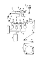
図1に、直接印刷方式長尺ウェブ用相変化インクプリンタの概略立面を示す。このプリンタで使用する媒体は、紙、プラスチック等の印刷向け素材からなる長尺な(即ち実質的に途切れがない)ウェブWである。ウェブWはスプール10に巻かれて装填されており、必要に応じスプール10から引き出され、図示しない種々のモータによってプリンタ内に送られていく。引き出されて所定の経路沿いに運ばれていくウェブWは、一組のローラ12によってぴんと張った状態に保たれまたその張り具合が調節される。
FIG. 1 shows a schematic elevation of a direct printing type long web phase change ink printer. The medium used in this printer is a long (ie, substantially uninterrupted) web W made of a printing material such as paper or plastic. The web W is wound around the spool 10 and loaded. The web W is pulled out from the spool 10 as necessary, and is sent into the printer by various motors (not shown). The web W that is pulled out and carried along a predetermined path is kept taut by a pair of
その下流にあるプレヒータ即ち予熱器18は、印刷に先立ちウェブWの温度を所定の予熱温度まで加熱する。この加熱は接触、輻射、伝熱、対流等の方式で行い、その目標となる予熱温度は例えば約30〜70℃の範囲内で設定する。
A preheater or
ウェブWはその下流の印刷部20に入っていく。印刷部20には一組のプリントヘッド21(図中、21A〜21D)が設けられている。各プリントヘッド21はウェブWのほぼ全幅をカバーするようウェブ横断方向に沿って延びており、また動いているウェブW上に直接即ち中間転写部材を介さずインクを被着させうるよう構成、配置されている。また、各プリントヘッド21はいずれかの成分色(例えば四色のうち一色)を担当しており、画像伝送路22経由で受け取った画像データに基づき、自分が担当する色の成分色画像を形成する。自明な通り、こうして複数の成分色画像をウェブW上の同一部位に重ねて形成することで、その画像データによって表されているフルカラー画像をウェブW上に形成することができる。なお、各プリントヘッド21を単線状のリニアアレイにすること、同一の成分色を複数個のプリントヘッド21に担当させること、同じ色を担うプリントヘッド21同士でその位置をプロセス方向Pに沿ってずらすこと、その全体又は一部をプロセス方向Pと交差する方向に沿って動かしスポット色印刷を行えるようにプリントヘッド21を実装すること等も可能である。
The web W enters the
本実施形態でウェブW上に被着させるインクは相変化インクである。相変化インクは室温でほぼ固体であるので、ウェブWに向け吐出する前に液化させる必要がある。相変化インクとしては、現在広く用いられているタイプのもの、即ち約100〜140℃まで加熱すると液相になるものを使用するとよい。一般的に言って、ウェブWに向け吐出されたインクは、ウェブWに射突した直後から冷め始める。 The ink deposited on the web W in this embodiment is phase change ink. Since the phase change ink is almost solid at room temperature, it needs to be liquefied before being ejected toward the web W. As the phase change ink, it is preferable to use a type which is widely used at present, that is, a liquid phase which is heated to about 100 to 140 ° C. Generally speaking, the ink discharged toward the web W starts to cool immediately after it hits the web W.
各プリントヘッド21に対応して設けられているバー状又はローラ状の部材はバッキング即ち裏打ち材24(図中、24A〜24D)である。裏打ち材24は、対応するプリントヘッド21とは逆側からウェブWに面するよう配置されている。ウェブWの位置は各裏打ち材24によって規制されており、その位置規制によりプリントヘッド21とウェブWの間隔が所定距離に保たれている。各裏打ち材24はその温度を制御できるよう構成されており、ウェブWのうち裏打ち材24の近くを通っている部分の温度が所定のインク受入温度例えば約40〜60℃の域内で設定した温度より低くなることを、その温度制御によって防ぐことができる。例えば、裏打ち材24の内部に加熱素子や液体通流用空洞を設けて温度を制御するようにしてもよいし、気体例えば空気をウェブWの一部分に流し(送り込み又は吸い出し)その気流を以てその部分の裏打ち“材”24として使用してもよい。予熱器18による予熱に加えて、裏打ち材24の温度を所定の目標温度に保つことは、印刷部内ウェブ温度を所定の温度域例えば約45〜65℃の域内に保つのに役に立つ。
A bar-like or roller-like member provided corresponding to each print head 21 is a backing or backing material 24 (24A to 24D in the figure). The backing material 24 is disposed so as to face the web W from the side opposite to the corresponding print head 21. The position of the web W is regulated by each backing material 24, and the distance between the print head 21 and the web W is kept at a predetermined distance by the position regulation. Each backing material 24 is configured so that its temperature can be controlled, and the temperature of the portion of the web W that passes near the backing material 24 is set at a predetermined ink receiving temperature, for example, about 40-60 ° C. Lowering can be prevented by the temperature control. For example, a heating element or a liquid flow cavity may be provided inside the backing material 24 to control the temperature, or a gas, for example, air, is flowed (feeded or sucked out) into a part of the web W, and the airflow is used for the part. The backing “material” 24 may be used. In addition to preheating by the
また、印刷部20内に運ばれてきたウェブW上に様々な色のインクを順次被着させて画像を形成するには、印刷部内ウェブ温度ばらつきを所定程度以下に抑える必要がある。即ち、吐出されるインクの温度はその被着先たるウェブWの温度よりかなり高く、インクが被着すると普通は被着個所周辺のウェブ形成素材(紙等)が昇温するので、印刷部内ウェブ温度ばらつきを所望限度内に抑えるには、印刷部20内でウェブWに接触又は接近する物体の挙動を然るべく調整する必要がある。印刷部内ウェブ温度は、裏打ち材24の作用だけでなく例えばウェブWの表面又は背面に流れる空気の温度や流速によっても大きく左右されるので、印刷部内ウェブ温度を制御する際にはそうした要素も考慮すべきである。即ち、例えばウェブWの背面に空気を流すエアブロワやファンを印刷部20に設け、それによって印刷部内ウェブ温度を調節するのが望ましい。
In addition, in order to form an image by sequentially depositing inks of various colors on the web W carried into the
こうして印刷部内ウェブ温度をほぼ均一化すること、即ちプリントヘッド21から吐出されるインクの被着による印刷部内ウェブ温度ばらつきを概ねなくすことは、形成される画像の品質を確保する上で有益である。とりわけ、ウェブ横断方向(幅方向)例えばクロスプロセス方向に沿ったインクの延び即ちスプレッドや、ウェブW内へのインクの浸透度即ちペネトレーションを安定化する上で、この温度均一性は重要である。使用するインク及びウェブWの熱特性にもよるが、裏打ち材24を制御せず専らウェブWの予熱で温度均一性を実現するやり方でも、また印刷部内ウェブ温度ばらつきがほとんどなくなるよう各裏打ち材24を互いに別々の温度に制御するやり方でも、こうした温度均一性を実現することができる。裏打ち材個別制御等を実現するには、例えば、図示しない温度センサによってウェブWの温度を検知し制御するシステムと共に、各時点で各プリントヘッド21から吐出されウェブWに被着する各色インクの量を計測し又は画像データ等に基づき推量するシステムを設けるのが望ましい。裏打ち材個別制御に際しては、各裏打ち材24に対応するプリントヘッド21からの入力データだけでなく、印刷部20内に存する他のプリントヘッド21からの入力データも使用するとよい。
Thus, making the web temperature in the printing unit substantially uniform, that is, eliminating the variation in the web temperature in the printing unit due to the deposition of the ink ejected from the print head 21 is beneficial in securing the quality of the formed image. . In particular, this temperature uniformity is important in stabilizing the extension or spread of ink along the cross-web direction (width direction), for example, the cross-process direction, and the penetration or penetration of the ink into the web W. Depending on the ink to be used and the thermal characteristics of the web W, each backing material 24 can also be used in a manner in which temperature uniformity is achieved by preheating the web W exclusively without controlling the backing material 24, and so that there is almost no variation in the web temperature in the printing section. Such temperature uniformity can also be achieved by controlling the temperatures at different temperatures. In order to realize individual control of the backing material, for example, together with a system that detects and controls the temperature of the web W by a temperature sensor (not shown), the amount of each color ink that is ejected from each print head 21 and adheres to the web W at each time point It is desirable to provide a system for measuring or estimating based on image data or the like. In the individual control of the backing material, not only the input data from the print head 21 corresponding to each backing material 24 but also the input data from other print heads 21 existing in the
印刷部20から出たウェブWは、その下流にある一組のテンションローラ26を通って、更にその下流にある1個又は複数個のミッドヒータ即ち中間加熱器30に入っていく。中間加熱器30は接触、輻射、伝熱、対流等の加熱方式によってウェブWを加熱し目標温度まで昇温させる。その目標温度は例えば約35〜80℃の温度域内にするのが望ましい。中間加熱器30でウェブWを加熱することによって、ウェブW上のインクの温度を適切な温度、即ち圧延器40を通る際にウェブW上のインクが有しているべき温度にすることができ、またインク・ウェブW間の温度差を約15℃以内に抑えることができる。なお、ウェブW及びインクを中間加熱器30で後述の圧延器温度より0〜20℃高い温度にするのは、インク温度が低すぎるとラインをうまく押し延ばせなくなり、高すぎると印刷した画像が裏側から透けて見える印刷物になってしまうからである。
The web W coming out of the
中間加熱器30を出たウェブWはその下流にあるスプレッダ即ち圧延器40に入り、その圧延器40によって所定の圧力で加圧(及び加熱)される。圧延器40の役目は、隣接インク滴間の隙間が埋まり画像中の塗りつぶし部分が均質になるよう、ウェブWにしっかりと付着していないインク滴を加圧(及び加熱)によってウェブW上に塗りつけ、インク層の途切れを減らすことである。圧延器40を使用することによって、こうしてインクを押し延ばすことだけでなく、インク層の凝集度やインク・ウェブW間接着度を高めて画質を向上させることもできる。また、圧延器40はローラによってウェブWを加圧(及び加熱)する構成にするとよい。図示例では像側ローラ42及び加圧ローラ44を使用してウェブWを加圧している。ウェブWを加熱するなら、いずれかのローラに加熱素子(図示例では46)を組み込み、例えば約35〜80℃の域内の温度まで加熱するとよい。
The web W exiting the
この圧延器内ローラ温度はとりわけ約55℃に保つのが望ましい。それは、圧延器内ローラ温度が低すぎるとラインをうまく押し延ばせず高すぎると光沢欠陥が発生する傾向があるからである。圧延器内ローラ温度が57℃より高い場合、インクがローラ上に転写されることもある。また、圧延器内ローラの間隙で発生させる圧力は、例えば約500〜2000psiにするとよい(1psi=約6895Pa)。この圧力が低すぎるとラインをうまく押し延ばせず高すぎるとローラ寿命が短くなる。 It is desirable to keep the roller temperature in the rolling mill at about 55 ° C. This is because if the roller temperature in the rolling mill is too low, the line cannot be stretched well, and if it is too high, gloss defects tend to occur. When the roller temperature in the rolling mill is higher than 57 ° C., the ink may be transferred onto the roller. The pressure generated in the gap between the rollers in the rolling mill may be, for example, about 500 to 2000 psi (1 psi = about 6895 Pa). If this pressure is too low, the line will not be stretched well, and if it is too high, the roller life will be shortened.
圧延器40には、更に、ローラ表面に清掃を施しまた物質層例えば潤滑層の形成処置を施す清掃潤滑部48を設けるとよい。図示例では像側ローラ42側に清掃潤滑部48を設けている。清掃潤滑部48にて圧延器内ローラ表面に層をなすよう被着させる潤滑剤は、例えばその粘度が約10〜200センチポイズのアミノシリコーンオイルである。ウェブWによって運び去られる潤滑剤の量がA4用紙1枚分当たり約1〜10mgと僅かであるので、使用する潤滑剤の量も僅かですむ。
The rolling
更に、中間加熱器30と圧延器40を単一ユニット化し、ウェブW上の同一部位に対し両者の機能を同時に発揮させるようにしてもよい。
Furthermore, the
そして、本実施形態のプリンタでは、画像の光沢を調整するグロッサ即ち光沢器50が圧延器40の下流に設けられている。但し、これを省いた形態で本発明を実施することもできる。光沢器50は、圧延器40によって押し延ばされた直後のインクに適当な温度及び圧力を加えその光沢状態を所望の状態にする部材であり、2個のローラ即ち像側ローラ52及び加圧ローラ54から構成されている。ウェブWはローラ52とローラ54の間隙に通されるので、いずれかのローラの表面に適当なテキスチャを形成しておくことで、ユーザが望む模様をインク層の表面に刻印することができる。圧延器40における制御目標温度が約35〜80℃であるなら、光沢器50における制御目標温度は約30〜70℃にするとよい。
In the printer of this embodiment, a glosser for adjusting the gloss of an image, that is, a
圧延器40及び光沢器50を構成するローラのうち像側ローラ42及び52は、ウェブWのインク被着面に接触するので十分な硬度が必要であり、従って陽極酸化アルミニウム等によって形成するのが望ましい。対するに、加圧ローラ44及び54としてはより硬度が低いものを使用する。そのデュロメータ値は約50〜65D程度でよく、弾性係数は約65〜115MPa程度でよい。また、加圧ローラ44及び54には薄いエラストマ被覆を設けるとよい。例えばエラストマやラバーの層を有する単層型又は多層型加圧ローラなら、有効弾性係数を約50〜200MPaの範囲内にすることができる。
Of the rollers constituting the rolling
圧延器40内温度及び光沢器50内温度は、いずれも、その時々の動作状態や必要とされる印刷(物)属性に応じ且つ図示しない制御システムによって、所望の光沢が得られるよう詳細に調整、制御するとよい。
The temperature inside the rolling
圧延器40内及び光沢器50内でローラ対がウェブWに加える圧力は、例えば約500〜2000psiの範囲内にするとよい。インク組成が柔軟性に富んでおり高い圧力を加えると延びすぎるような場合には、インク組成に応じ圧力を調整するのが望ましい。また、光沢器50内にある像側ローラ52の表面テキスチャを様々に変えてインク表面にそれを刻印する際には、その刻印がうまくいくよう温度や圧力を高めにするとよい。
The pressure applied by the roller pair to the web W in the rolling
なお、本件技術分野において習熟を積まれた方々(いわゆる当業者)にはご理解頂ける通り、温度や圧力を加えることによってインクを押し延ばす手法は、そのインクがそれにふさわしい形態乃至組成及び熱特性を有している場合に有効である。例えば相変化インクではなく溶剤ベースや水ベースのインクを用い上記同様の構成のプリンタで印刷を行ったとしたら、ウェブW上に被着したインク滴が滴のままでいることは少なく、通常は自然に延び広がって滑らかな層を形成するので、溶剤ベースや水ベースのインクでは圧延器40等の部材の効果がはっきりしない。同様に、例えば繊維製の編み物や織布等のような概ね多孔質の媒体にインク乃至染料を被着させそれを圧延器40に通したとしたら、そのインクは圧延器40によってその媒体例えば布から絞り出されてしまうので、その種の媒体及びインクに関する先行技術は本発明と相容れない。即ち、これらの論拠を含め種々の論拠によって裏付けられる通り、溶剤ベースや水ベースのインクを種々のウェブ上に被着させる従来技術は、本発明とは相容れないものである。
As can be understood by those skilled in this technical field (so-called persons skilled in the art), the method of stretching ink by applying temperature or pressure has the form, composition and thermal characteristics suitable for it. It is effective when For example, if solvent-based or water-based ink is used instead of phase change ink and printing is performed with a printer having the same configuration as described above, ink droplets deposited on the web W are rarely left as droplets, and are usually natural. Therefore, the effect of the member such as the rolling
また、圧延器40や光沢器50を通過したウェブW即ちその片面への印刷が済んだウェブWは、必要なら再びプリンタに通して裏面に画像を印刷した上で、頁毎に切断して図示しないバインディング等の処置に供する。更に、実質的に途切れのない長尺ウェブW上への印刷を例として説明を行ったが、本発明はカットシート向け印刷システムにも同様に適用することができる。そして、予熱器18、中間加熱器30、圧延器40等の設定温度は、使用する媒体例えばウェブWの種類、重量等に応じて定めるとよい。
In addition, the web W that has passed through the rolling
10 スプール、12,26,42,44,52,54 ローラ、18 予熱器、20 印刷部、21A〜21D プリントヘッド、22 画像伝送路、24A〜24D 裏打ち材、30 中間加熱器、40 圧延器、46 加熱素子、48 清掃潤滑部、50 光沢器、P プロセス方向、W ウェブ。 10 spool, 12, 26, 42, 44, 52, 54 roller, 18 preheater, 20 printing section, 21A-21D print head, 22 image transmission path, 24A-24D backing material, 30 intermediate heater, 40 rolling mill, 46 heating elements, 48 cleaning lubrication, 50 gloss, P process direction, W web.
Claims (10)
上記印刷部が、上記経路を移動する上記媒体に相変化インクを被着させる少なくとも第1プリントヘッド及び第2プリントヘッドを有し、さらに上記第1プリントヘッドに対向する、上記経路上の位置に配置された第1裏打ち材と、上記第2プリントヘッドに対向する、上記経路上の位置に配置された第2裏打ち材とを有し、
上記第1裏打ち材及び第2裏打ち材により、当該裏打ち材とこれに対応するプリントヘッドの間を通過する媒体を所定のインク受入温度域内の温度に到達させ、上記第1裏打ち材に対応するインク受入温度と上記第2裏打ち材に対応するインク受入温度とが、印刷ゾーンを通じて一定の媒体温度が得られるように、個別に制御可能である、
印刷装置。 Means for feeding the medium along the path, and a printing unit arranged along the path,
The printing unit has at least a first print head and a second print head for depositing phase change ink on the medium moving along the path, and further, at a position on the path facing the first print head. A first backing material disposed; and a second backing material disposed at a position on the path facing the second print head;
The first backing material and the second backing material cause the medium passing between the backing material and the corresponding print head to reach a temperature within a predetermined ink receiving temperature range, and the ink corresponding to the first backing material. an ink receiving temperature corresponding to receiving temperature and the second backing material, as the medium temperature in the first constant through the print zone and thus can control individually,
Printing device.
上記印刷部が、上記経路を移動する上記媒体に相変化インクを被着させる少なくとも第1プリントヘッド及び第2プリントヘッドを有し、さらに上記第1プリントヘッドに対向する、上記経路上の位置に配置された第1裏打ち材と、上記第2プリントヘッドに対向する、上記経路上の位置に配置された第2裏打ち材とを有し、
上記第1裏打ち材及び第2裏打ち材により、当該裏打ち材とこれに対応するプリントヘッドの間を通過する媒体を所定のインク受入温度域内の温度に到達させ、上記第1裏打ち材に対応するインク受入温度と上記第2裏打ち材に対応するインク受入温度とが、印刷ゾーンを通じて一定の媒体温度が得られるように、個別に制御可能である、
印刷装置。 Means for feeding the medium along the path, a preheater for setting the temperature of the medium to a predetermined preheating temperature, and a printing unit arranged along the path,
The printing unit has at least a first print head and a second print head for depositing phase change ink on the medium moving along the path, and further, at a position on the path facing the first print head. A first backing material disposed; and a second backing material disposed at a position on the path facing the second print head;
The first backing material and the second backing material cause the medium passing between the backing material and the corresponding print head to reach a temperature within a predetermined ink receiving temperature range, and the ink corresponding to the first backing material. an ink receiving temperature corresponding to receiving temperature and the second backing material, as the medium temperature in the first constant through the print zone and thus can control individually,
Printing device.
上記印刷部が、上記経路を移動する上記媒体に相変化インクを被着させる少なくとも第1プリントヘッド及び第2プリントヘッドを有し、さらに上記第1プリントヘッドに対向する、上記経路上の位置に配置された第1裏打ち材と、上記第2プリントヘッドに対向する、上記経路上の位置に配置された第2裏打ち材とを有し、
上記第1裏打ち材及び第2裏打ち材により、上当該打ち材とこれに対応するプリントヘッドの間を通過する媒体を所定のインク受入温度域内の温度に到達させ、上記第1裏打ち材に対応するインク受入温度と上記第2裏打ち材に対応するインク受入温度とが、印刷ゾーンを通じて一定の媒体温度が得られるように、個別に制御可能である、
印刷装置。 Means for feeding the medium along the path; a printing unit disposed along the path; an intermediate heater disposed downstream from the printing unit along the path; and downstream from the intermediate heater along the path A rolling mill disposed and pressurizing the medium,
The printing unit has at least a first print head and a second print head for depositing phase change ink on the medium moving along the path, and further, at a position on the path facing the first print head. A first backing material disposed; and a second backing material disposed at a position on the path facing the second print head;
The first backing material and the second backing material cause the medium passing between the upper backing material and the corresponding print head to reach a temperature within a predetermined ink receiving temperature range, and corresponds to the first backing material. an ink receiving temperature corresponding to the ink receiving temperature and the second backing material, as the medium temperature in the first constant through the print zone and thus can control individually,
Printing device.
Applications Claiming Priority (2)
| Application Number | Priority Date | Filing Date | Title |
|---|---|---|---|
| US11/773,549 | 2007-07-05 | ||
| US11/773,549 US7828423B2 (en) | 2007-07-05 | 2007-07-05 | Ink-jet printer using phase-change ink printing on a continuous web |
Publications (3)
| Publication Number | Publication Date |
|---|---|
| JP2009012467A JP2009012467A (en) | 2009-01-22 |
| JP2009012467A5 JP2009012467A5 (en) | 2012-01-19 |
| JP4898747B2 true JP4898747B2 (en) | 2012-03-21 |
Family
ID=39734163
Family Applications (1)
| Application Number | Title | Priority Date | Filing Date |
|---|---|---|---|
| JP2008169721A Expired - Fee Related JP4898747B2 (en) | 2007-07-05 | 2008-06-30 | Inkjet printer for long web printing using phase change ink |
Country Status (5)
| Country | Link |
|---|---|
| US (1) | US7828423B2 (en) |
| EP (1) | EP2011659B1 (en) |
| JP (1) | JP4898747B2 (en) |
| KR (1) | KR101218565B1 (en) |
| CN (1) | CN101337458B (en) |
Families Citing this family (30)
| Publication number | Priority date | Publication date | Assignee | Title |
|---|---|---|---|---|
| US20100259573A1 (en) * | 2009-04-13 | 2010-10-14 | Xerox Corporation | Method of controlling marking on continuous web print media |
| US8042930B2 (en) * | 2009-04-28 | 2011-10-25 | Xerox Corporation | Method of servicing a drum maintenance unit (DMU) in an image generating system |
| US8384748B2 (en) * | 2009-07-29 | 2013-02-26 | Xerox Corporation | Fabrication of improved aluminum rollers with low adhesion and ultra/super hydrophobicity and/or oleophobicity by electrospinning technique in solid ink-jet marking |
| US8192005B2 (en) * | 2009-07-29 | 2012-06-05 | Xerox Corporation | Rollers for phase-change ink printing |
| US8162469B2 (en) * | 2009-09-17 | 2012-04-24 | Xerox Corporation | Method for achieving uniform media temperature and size throughout the pre-heat zone |
| US8220918B2 (en) * | 2009-12-21 | 2012-07-17 | Xerox Corporation | Spreader module for duplex continuous feed imaging devices |
| US8340546B2 (en) | 2010-04-06 | 2012-12-25 | Xerox Corporation | Dual function charging device and charge patterning device cleaner |
| US8303103B2 (en) | 2010-05-28 | 2012-11-06 | Xerox Corporation | Peak position drum maintenance unit for a printing device |
| US8369768B2 (en) | 2010-06-17 | 2013-02-05 | Xerox Corporation | Cleaning blade parameter adjustment system |
| US8280287B2 (en) | 2010-08-12 | 2012-10-02 | Xerox Corporation | Multi-stage fixing systems, printing apparatuses and methods of fixing marking material to substrates |
| US8422926B2 (en) | 2010-08-12 | 2013-04-16 | Xerox Corporation | Fixing devices including low-viscosity release agent applicator system and methods of fixing marking material to substrates |
| US8478178B2 (en) | 2010-08-12 | 2013-07-02 | Xerox Corporation | Fixing devices for fixing marking material to a web with contact pre-heating of web and marking material and methods of fixing marking material to a web |
| US8897683B2 (en) | 2010-08-12 | 2014-11-25 | Xerox Corporation | Fixing systems including image conditioner and image pre-heater and methods of fixing marking material to substrates |
| US8265536B2 (en) | 2010-08-12 | 2012-09-11 | Xerox Corporation | Fixing systems including contact pre-heater and methods for fixing marking material to substrates |
| US20120039649A1 (en) * | 2010-08-12 | 2012-02-16 | Xerox Corporation | Fixing apparatus, systems, and methods for printing |
| US8660682B2 (en) * | 2010-11-22 | 2014-02-25 | Honeywell Asca Inc. | Air wipe and sheet guide temperature control on paper and continuous web scanners |
| WO2012077432A1 (en) * | 2010-12-10 | 2012-06-14 | コニカミノルタホールディングス株式会社 | Inkjet recording device |
| US8740325B2 (en) | 2010-12-13 | 2014-06-03 | Xerox Corporation | Method for printing in a printer having an inoperable ink reservoir |
| US8666188B2 (en) | 2011-03-23 | 2014-03-04 | Xerox Corporation | Identifying edges of web media using textural contrast between web media and backer roll |
| US8702186B2 (en) * | 2012-01-26 | 2014-04-22 | Xerox Corporation | Method and apparatus for ink recirculation |
| US9676202B2 (en) * | 2012-05-09 | 2017-06-13 | Xerox Corporation | System and method for detecting defects in an inkjet printer |
| US8668318B2 (en) | 2012-07-26 | 2014-03-11 | Xerox Corporation | System and method for spreading ink on a media web |
| US8740337B2 (en) * | 2012-07-31 | 2014-06-03 | Eastman Kodak Company | Wrinkle elimination for solid inkjet web printer |
| US8827439B2 (en) * | 2012-08-20 | 2014-09-09 | Xerox Corporation | Self-cleaning media perforator |
| JP5978853B2 (en) * | 2012-08-21 | 2016-08-24 | セイコーエプソン株式会社 | Liquid ejector |
| US9027477B2 (en) * | 2013-03-28 | 2015-05-12 | Xerox Corporation | Wrinkle detection in continuous feed printers |
| US9010925B2 (en) | 2013-07-15 | 2015-04-21 | Xerox Corporation | Air film support device for an inkjet printer |
| US9403358B1 (en) * | 2015-04-17 | 2016-08-02 | Xerox Corporation | System and method for forming hydrophobic structures in a hydrophilic print medium |
| KR102444364B1 (en) * | 2019-03-26 | 2022-09-16 | 주식회사 아르볼소피아 | A printing method including a surface treatment function, and a printing method using the printing method |
| KR102261210B1 (en) * | 2019-03-26 | 2021-06-04 | 주식회사 아르볼소피아 | Printing apparatus including surface treatment function |
Family Cites Families (20)
| Publication number | Priority date | Publication date | Assignee | Title |
|---|---|---|---|---|
| JPH0226747A (en) | 1988-07-18 | 1990-01-29 | Brother Ind Ltd | Hot melt type ink jet printer |
| US5287123A (en) | 1992-05-01 | 1994-02-15 | Hewlett-Packard Company | Preheat roller for thermal ink-jet printer |
| US5406315A (en) | 1992-07-31 | 1995-04-11 | Hewlett-Packard Company | Method and system for remote-sensing ink temperature and melt-on-demand control for a hot melt ink jet printer |
| US5502476A (en) * | 1992-11-25 | 1996-03-26 | Tektronix, Inc. | Method and apparatus for controlling phase-change ink temperature during a transfer printing process |
| US5389958A (en) | 1992-11-25 | 1995-02-14 | Tektronix, Inc. | Imaging process |
| JP2936377B2 (en) * | 1992-11-25 | 1999-08-23 | テクトロニクス・インコーポレイテッド | Image forming method |
| JPH06220781A (en) | 1993-01-28 | 1994-08-09 | Kanebo Ltd | Printing method and apparatus therefor |
| US5742315A (en) * | 1995-09-05 | 1998-04-21 | Xerox Corporation | Segmented flexible heater for drying a printed image |
| US5793398A (en) | 1995-11-29 | 1998-08-11 | Levi Strauss & Co. | Hot melt ink jet shademarking system for use with automatic fabric spreading apparatus |
| US5777650A (en) | 1996-11-06 | 1998-07-07 | Tektronix, Inc. | Pressure roller |
| JPH1120141A (en) * | 1997-07-02 | 1999-01-26 | Brother Ind Ltd | Hot melt ink jet printer |
| US6113231A (en) | 1998-02-25 | 2000-09-05 | Xerox Corporation | Phase change ink printing architecture suitable for high speed imaging |
| US6196675B1 (en) | 1998-02-25 | 2001-03-06 | Xerox Corporation | Apparatus and method for image fusing |
| JP2000141621A (en) * | 1998-11-10 | 2000-05-23 | Brother Ind Ltd | Image forming apparatus |
| JP2000296607A (en) * | 1999-04-16 | 2000-10-24 | Mutoh Ind Ltd | Ink jet printer |
| US6361230B1 (en) | 1999-09-17 | 2002-03-26 | Macdermid Acumen, Inc. | Printing zone specially adapted for textile printing media |
| US6485140B1 (en) | 1999-11-30 | 2002-11-26 | Macdermid Acumen, Inc. | Auxiliary underside media dryer |
| US6494570B1 (en) | 2001-12-04 | 2002-12-17 | Xerox Corporation | Controlling gloss in an offset ink jet printer |
| US6932526B2 (en) | 2003-11-21 | 2005-08-23 | Xerox Corporation | Multi-stage pre-transfer substrate heating assembly |
| DE602005013480D1 (en) * | 2004-12-29 | 2009-05-07 | Oce Tech Bv | Temperature control system for blade support plate of a printer |
-
2007
- 2007-07-05 US US11/773,549 patent/US7828423B2/en active Active
-
2008
- 2008-06-30 JP JP2008169721A patent/JP4898747B2/en not_active Expired - Fee Related
- 2008-07-04 EP EP08159751.0A patent/EP2011659B1/en not_active Expired - Fee Related
- 2008-07-04 CN CN2008101282635A patent/CN101337458B/en not_active Expired - Fee Related
- 2008-07-04 KR KR1020080064756A patent/KR101218565B1/en active IP Right Grant
Also Published As
| Publication number | Publication date |
|---|---|
| CN101337458B (en) | 2013-07-17 |
| US7828423B2 (en) | 2010-11-09 |
| KR20090004737A (en) | 2009-01-12 |
| US20090009573A1 (en) | 2009-01-08 |
| KR101218565B1 (en) | 2013-01-07 |
| EP2011659A1 (en) | 2009-01-07 |
| JP2009012467A (en) | 2009-01-22 |
| EP2011659B1 (en) | 2013-04-17 |
| CN101337458A (en) | 2009-01-07 |
Similar Documents
| Publication | Publication Date | Title |
|---|---|---|
| JP4898747B2 (en) | Inkjet printer for long web printing using phase change ink | |
| US8152288B2 (en) | Method and system for achieving uniform ink and web temperatures for spreading | |
| US20090141110A1 (en) | Ink-jet printer using phase-change ink for direct on paper printing | |
| US8350879B2 (en) | Non-contact heating of solid ink prints after ink fixing | |
| US8262186B2 (en) | Pre-leveler cooling device for continuous feed imaging devices | |
| US8579406B2 (en) | Real time bleed-though detection for continuous web printers | |
| US8162469B2 (en) | Method for achieving uniform media temperature and size throughout the pre-heat zone | |
| JP2008155644A5 (en) | ||
| JP2009012467A5 (en) | ||
| US8646385B2 (en) | Media inversion system for a continuous web printer | |
| CN105517804A (en) | Digital printing system | |
| JP2008155644A (en) | Device for controlling feeding of ink in inking arrangement | |
| US9682573B2 (en) | Printer having edge control apparatus for web media | |
| US8220918B2 (en) | Spreader module for duplex continuous feed imaging devices | |
| JP5466591B2 (en) | Phase change ink printing roller | |
| KR20130124430A (en) | Image transfer system for use in an indirect printer and replaceable unit configured for mounting in an image transfer system | |
| US20090324818A1 (en) | Silicone applicator for a printing press | |
| US20140125730A1 (en) | Method for Printing Phase Change Ink onto Porous Media | |
| KR20100105432A (en) | Method of forming a nip with a skewed transfix roll | |
| JP5202664B2 (en) | Particle dispersion supply apparatus and image forming apparatus | |
| JP7155945B2 (en) | Recording medium heating device, liquid ejection device | |
| CN109968832A (en) | Ink-jet recording apparatus | |
| CN112654501B (en) | Adjusting roller | |
| US20110111125A1 (en) | Dithered Printing of Clear Ink to Reduce Rub and Offset | |
| JP2012171188A (en) | Particle dispersion supplying apparatus and image forming apparatus |
Legal Events
| Date | Code | Title | Description |
|---|---|---|---|
| A521 | Request for written amendment filed |
Free format text: JAPANESE INTERMEDIATE CODE: A523 Effective date: 20110624 |
|
| A621 | Written request for application examination |
Free format text: JAPANESE INTERMEDIATE CODE: A621 Effective date: 20110624 |
|
| A521 | Request for written amendment filed |
Free format text: JAPANESE INTERMEDIATE CODE: A523 Effective date: 20111124 |
|
| A871 | Explanation of circumstances concerning accelerated examination |
Free format text: JAPANESE INTERMEDIATE CODE: A871 Effective date: 20111124 |
|
| TRDD | Decision of grant or rejection written | ||
| A975 | Report on accelerated examination |
Free format text: JAPANESE INTERMEDIATE CODE: A971005 Effective date: 20111201 |
|
| A01 | Written decision to grant a patent or to grant a registration (utility model) |
Free format text: JAPANESE INTERMEDIATE CODE: A01 Effective date: 20111206 |
|
| A01 | Written decision to grant a patent or to grant a registration (utility model) |
Free format text: JAPANESE INTERMEDIATE CODE: A01 |
|
| A61 | First payment of annual fees (during grant procedure) |
Free format text: JAPANESE INTERMEDIATE CODE: A61 Effective date: 20111226 |
|
| R150 | Certificate of patent or registration of utility model |
Ref document number: 4898747 Country of ref document: JP Free format text: JAPANESE INTERMEDIATE CODE: R150 Free format text: JAPANESE INTERMEDIATE CODE: R150 |
|
| FPAY | Renewal fee payment (event date is renewal date of database) |
Free format text: PAYMENT UNTIL: 20150106 Year of fee payment: 3 |
|
| R250 | Receipt of annual fees |
Free format text: JAPANESE INTERMEDIATE CODE: R250 |
|
| R250 | Receipt of annual fees |
Free format text: JAPANESE INTERMEDIATE CODE: R250 |
|
| R250 | Receipt of annual fees |
Free format text: JAPANESE INTERMEDIATE CODE: R250 |
|
| R250 | Receipt of annual fees |
Free format text: JAPANESE INTERMEDIATE CODE: R250 |
|
| R250 | Receipt of annual fees |
Free format text: JAPANESE INTERMEDIATE CODE: R250 |
|
| R250 | Receipt of annual fees |
Free format text: JAPANESE INTERMEDIATE CODE: R250 |
|
| LAPS | Cancellation because of no payment of annual fees |