JP4897397B2 - UV irradiation equipment - Google Patents
UV irradiation equipment Download PDFInfo
- Publication number
- JP4897397B2 JP4897397B2 JP2006230080A JP2006230080A JP4897397B2 JP 4897397 B2 JP4897397 B2 JP 4897397B2 JP 2006230080 A JP2006230080 A JP 2006230080A JP 2006230080 A JP2006230080 A JP 2006230080A JP 4897397 B2 JP4897397 B2 JP 4897397B2
- Authority
- JP
- Japan
- Prior art keywords
- ultraviolet
- short arc
- mercury lamp
- arc type
- lighting
- Prior art date
- Legal status (The legal status is an assumption and is not a legal conclusion. Google has not performed a legal analysis and makes no representation as to the accuracy of the status listed.)
- Expired - Fee Related
Links
Images


Landscapes
- Exposure And Positioning Against Photoresist Photosensitive Materials (AREA)
- Discharge Lamps And Accessories Thereof (AREA)
- Exposure Of Semiconductors, Excluding Electron Or Ion Beam Exposure (AREA)
Description
本発明は、ショートアーク形水銀ランプを紫外線光源として用いた紫外線照射装置に関する。 The present invention relates to an ultraviolet irradiation apparatus using a short arc type mercury lamp as an ultraviolet light source.
半導体露光や紫外線硬化形樹脂の硬化など多様な用途に紫外線照射装置が用いられている。このような紫外線照射装置では、紫外線光源としてショートアーク形の超高圧水銀ランプ(以下、ショートアーク形水銀ランプという。)が従来から使用されている。この紫外線照射装置には、ショートアーク形水銀ランプから放射される紫外線を楕円反射鏡で集光し、導光体を経由して外部へ導出するとともに、調光板を用いて紫外線量を所望量に調節し、かつシャッター板を用いて紫外線照射を行ったり遮断したりできるように構成されているタイプのものがある。 Ultraviolet irradiation devices are used for various purposes such as semiconductor exposure and curing of ultraviolet curable resins. In such an ultraviolet irradiation device, a short arc type ultra-high pressure mercury lamp (hereinafter referred to as a short arc type mercury lamp) has been conventionally used as an ultraviolet light source. In this ultraviolet irradiation device, ultraviolet rays radiated from a short arc type mercury lamp are condensed by an elliptical reflecting mirror, led out to the outside through a light guide, and a desired amount of ultraviolet rays is obtained using a light control plate. There is a type that is configured so that it can be adjusted and can be irradiated with ultraviolet rays using a shutter plate.
従来、半導体露光装置において、ショートアーク形水銀ランプの紫外線による照度を高めることにより、露光時間の短縮化および高効率化を目的として、ショートアーク形水銀ランプを連続点灯状態下で定格ランプ電力以下にして待機し、定格ランプ電力以上で露光を行うパルス点灯方式が知られている(例えば、特許文献1参照。)。 Conventionally, in semiconductor exposure equipment, the short arc type mercury lamp is reduced to less than the rated lamp power under continuous lighting for the purpose of shortening the exposure time and increasing the efficiency by increasing the illuminance of the short arc type mercury lamp by ultraviolet rays. There is known a pulse lighting system that waits for exposure at a rated lamp power or higher (see, for example, Patent Document 1).
そこで、前記紫外線照射装置におけるショートアーク形水銀ランプの点灯方式として上記パルス点灯方式を採用することが考えられる。この場合、以下に示すシーケンスを採用するのが一般的である。すなわち、ワークに対して安定した紫外線照度で露光しようとする場合、ショートアーク形水銀ランプに定格以上のランプ電力を投入して光レベルを上昇させてからシャッター開放を開始させ、シャッターが開放してからワークに対する露光を開始するシーケンスである。 Therefore, it is conceivable to employ the pulse lighting method as a lighting method of the short arc type mercury lamp in the ultraviolet irradiation device. In this case, the following sequence is generally adopted. In other words, when trying to expose the workpiece with a stable UV illumination, the lamp is opened after the lamp power exceeding the rating is applied to the short arc type mercury lamp to raise the light level and the shutter is opened. This is a sequence for starting the exposure of the workpiece from
ところが、紫外線照射装置においてワークに対する紫外線照射のタクトタイムを短縮することはワークの製品コストを低下させるうえで極めて重要であるが、従来技術を上記のように組み合わせた場合においては、安定した紫外線照射を行い、信頼性の高い紫外線照射装置が得られるものの、充分に短いタクトタイムの実現ができない。 However, shortening the tact time of ultraviolet irradiation on the workpiece in the ultraviolet irradiation device is extremely important for reducing the product cost of the workpiece. However, when the conventional technologies are combined as described above, stable ultraviolet irradiation is possible. Although a highly reliable ultraviolet irradiation device can be obtained, a sufficiently short tact time cannot be realized.
本発明は、紫外線照射のタクトタイムを短縮できる紫外線照射装置を提供することを目的とする。 An object of this invention is to provide the ultraviolet irradiation device which can shorten the tact time of ultraviolet irradiation.
本発明の紫外線照射装置は、ショートアーク形水銀ランプと;相対的大電力を供給してショートアーク形水銀ランプをフラッシュアップ点灯する第1の期間と相対的小電力を供給してショートアーク形水銀ランプの放電を持続させて待機点灯する第2の期間を交互に繰り返す点灯回路と;開閉動作を行ってショートアーク形水銀ランプから発生した紫外線を通過または遮断するシャッター機構と;シャッター機構を通過した紫外線をワークに照射する紫外線照射部と;を具備し、点灯回路における相対的大電力の投入立ち上がり開始時とシャッター機構の開放開始時とがほぼ一致するとともに、第1の期間における相対的大電力の投入による紫外線出力の立ち上がり時間をt1とし、シャッター機構の閉鎖状態から開放までのシャッター機構を通過する紫外線出力の立ち上がり時間をt2としたとき、時間t1およびt2が数式t2≧t1を満足するように構成され、フラッシュアップ点灯における光量立ち上がり時間を、0.2〜2.0秒に設定したことを特徴としている。 The ultraviolet irradiation apparatus of the present invention includes a short arc type mercury lamp; a first period in which a relatively large power is supplied to flash up the short arc type mercury lamp and a relatively small power is supplied, and a short arc type mercury is supplied. passing the shutter mechanism; shutter mechanism and to pass or block the ultraviolet rays generated from the short arc type mercury lamp performs opening and closing operations; the second lighting circuit repeats alternate periods and to wait lit by sustained discharge lamp An ultraviolet irradiation unit that irradiates the workpiece with the ultraviolet rays that are applied, and the start-up start time of the relatively large power in the lighting circuit substantially coincides with the start time of the opening of the shutter mechanism, and the relative large amount in the first period. The shutter mechanism from the closed state to the open state of the shutter mechanism, where t1 is the rise time of the UV output due to the power supply When the rise time of the UV output to pass to the t2, time t1 and t2 are configured so as to satisfy a formula t2 ≧ t1, the amount of light rising time in the flash-up lights, and set to 0.2 to 2.0 seconds It is characterized by that.
本発明によれば、ショートアーク形水銀ランプのフラッシュアップ点灯開始とシャッター機構の開放開始とがほぼ同時に行われるので、紫外線照射のタクトタイムを短縮できるとともに、フラッシュアップ時の紫外線出力が安定してから紫外線照射を開始できるので、所望積算量の紫外線照射を行いやすいとともに、安定した紫外線照射を行って信頼性の高い紫外線照射装置を提供することができる。 According to the present invention, the start of flash-up lighting of the short arc type mercury lamp and the start of opening of the shutter mechanism are performed almost simultaneously, so that the tact time of ultraviolet irradiation can be shortened and the ultraviolet output at the time of flash-up is stable. Since the ultraviolet irradiation can be started from the above, it is easy to perform the desired integrated amount of ultraviolet irradiation, and it is possible to provide a highly reliable ultraviolet irradiation apparatus by performing stable ultraviolet irradiation.
また、フラッシュアップ点灯における光量立ち上がり時間を0.2〜2.0秒に設定すれば、急激な陽極温度の上昇を回避することで電極物質の過度の飛散を抑制して紫外線の光束維持率時が向上した紫外線照射装置を提供することができる。 In addition, if the rise time of the light amount in flash-up lighting is set to 0.2 to 2.0 seconds, excessive scattering of the electrode material is suppressed by avoiding a rapid increase in the anode temperature, and at the time of maintaining the ultraviolet light flux. It is possible to provide an ultraviolet irradiating device with improved.
さらに、シャッター閉鎖後にフラッシュアップ点灯から待機点灯へ移行するように構成すれば、紫外線照射光量の積算制御を正確に行いやすい紫外線照射装置を提供することができる。 Furthermore, if it is configured to shift from flash-up lighting to standby lighting after the shutter is closed, it is possible to provide an ultraviolet irradiation device that can easily perform accurate control of the amount of ultraviolet irradiation.
さらにまた、シャッター機構の開放の確認信号を発生するように構成すれば、この確認信号を利用してワークの流れを制御して紫外線照射のタクトタイムを短縮しやすい紫外線照射装置を提供することができる。 Furthermore, if it is configured to generate a confirmation signal for opening the shutter mechanism, it is possible to provide an ultraviolet irradiation device that can easily reduce the tact time of ultraviolet irradiation by controlling the flow of the workpiece using this confirmation signal. it can.
さらにまた、ショートアーク形水銀ランプ、点灯回路、シャッター機構および紫外線照射部の少なくとも一部を収納し、容積V(cm3)のハウジングを具備し、ショートアーク形水銀ランプの相対的大電力で点灯する際のランプ電力がW(W)のとき、数式V/W≦45を満足するように構成すれば、小形化で、しかも消費電力が軽減される紫外線照射装置を提供することができる。 Furthermore, it houses at least a part of the short arc type mercury lamp, lighting circuit, shutter mechanism and ultraviolet irradiation part, and has a housing with a volume V (cm 3 ), which is lit with the relatively high power of the short arc type mercury lamp. When the lamp power at the time of W is W (W), if it is configured so as to satisfy the formula V / W ≦ 45, it is possible to provide an ultraviolet irradiation device that is downsized and consumes less power.
さらにまた、紫外線照射位置の確認をおこなうために可視光照射モードを選択可能にする場合、当該モード時にはショートアーク形水銀ランプを待機点灯することにより、可視光変換フィルタに照射されるエネルギー量を低減して当該フィルタの劣化を抑制してその短寿命化を阻止した紫外線照射装置を提供することができる。 Furthermore, when the visible light irradiation mode can be selected in order to check the ultraviolet irradiation position, the amount of energy irradiated to the visible light conversion filter is reduced by turning on the short arc mercury lamp in standby mode. And the ultraviolet irradiation device which suppressed deterioration of the said filter and prevented the shortening of the lifetime can be provided.
さらにまた、ショートアーク形水銀ランプに投入される電力をモニタすることにより、フラッシュアップ点灯時に所定のランプ電力が実際に投入されないエラーが発生するか否かをチェックするエラーチェック機能を充実して、所定の紫外線照射が行われることを確認できる紫外線照射装置を提供することができる。 Furthermore, by monitoring the power input to the short arc mercury lamp, we have enhanced an error check function that checks whether an error occurs when the specified lamp power is not actually applied when the flash is turned on. It is possible to provide an ultraviolet irradiation apparatus capable of confirming that predetermined ultraviolet irradiation is performed.
以下、図面を参照して本発明を実施するための形態を説明する。 Hereinafter, embodiments for carrying out the present invention will be described with reference to the drawings.
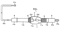
図1ないし図8は、本発明の紫外線照射装置を実施するための第1の形態を示し、図1は正面断面図、図2はショートアーク形水銀ランプの正面図、図3は点灯回路のブロック回路図、図4はランプ電力の波形図、図5はシャッター板の正面図、図6は紫外線照射装置の動作シーケンスを示す説明図、図7は調光板の正面図である。 1 to 8 show a first embodiment for carrying out the ultraviolet irradiation device of the present invention, FIG. 1 is a front sectional view, FIG. 2 is a front view of a short arc type mercury lamp, and FIG. 3 is a lighting circuit. 4 is a waveform diagram of the lamp power, FIG. 5 is a front view of the shutter plate, FIG. 6 is an explanatory view showing an operation sequence of the ultraviolet irradiation device, and FIG. 7 is a front view of the light control plate.
本形態の紫外線照射装置は、主構成要素としてショートアーク形水銀ランプSHL、点灯回路OC、シャッター機構SP、紫外線照射部UIRを具備している。 The ultraviolet irradiation apparatus of this embodiment includes a short arc type mercury lamp SHL, a lighting circuit OC, a shutter mechanism SP, and an ultraviolet irradiation unit UIR as main components.
また、本発明において所望により配設することができるその他の副次的な構成要素として、本形態においては、楕円反射鏡ER、ミラーM1、および調光機構DP、ハウジングHなどを具備している。 In addition, as other subsidiary components that can be arranged as desired in the present invention, the present embodiment includes an elliptical reflecting mirror ER, a mirror M1, a dimming mechanism DP, a housing H, and the like. .
〔ショートアーク形水銀ランプSHLについて〕 ショートアーク形水銀ランプSHLは、図2に示すように、透光性気密容器1、一対の電極2K、2A、外部リード構体3、4および放電媒体を備えている。
[About Short Arc Mercury Lamp SHL] As shown in FIG. 2, the short arc mercury lamp SHL includes a
透光性気密容器1は、耐火性を有する石英ガラスなどから形成され、例えば包囲部1aおよび一対の封止部1b、1bを備えている。包囲部1aの内部には放電空間1cが形成されている。封止部1bは、透光性気密容器1を気密に封止するとともに、後述する一対の電極2K、2Aを放電空間1c内に封装している。さらに詳述すれば、透光性気密容器1が石英ガラスからなる場合、封止部1bは、その内部に例えば封着金属箔(図示しない。)が気密に埋設されている。なお、封着金属箔は、例えばモリブデン箔からなり、所要の電流容量を得るために、1枚または並列状態で複数枚が用いられる。
The
一対の電極2K、2Aは、耐火性で導電性の金属、例えばタングステン(W)、レニウム(Re)またはタングステン−レニウム合金など、からなる。そして、直流点灯の場合、陰極2Kと陽極2Aで構成される。また、一対の電極2K、2Aは、包囲部1aの内径より小さい電極間距離、例えば2.8mmとなるようにそれぞれ先端が離間対向して配置されている。
The pair of
放電媒体は、水銀および希ガスを主体として構成されている。なお、水銀は、点灯時に蒸発して超高圧水銀蒸気状態を呈する。希ガスは、例えばアルゴンガスからなり、始動ガスおよび緩衝ガスとして作用する。 The discharge medium is mainly composed of mercury and a rare gas. In addition, mercury evaporates at the time of lighting and exhibits an ultra-high pressure mercury vapor state. The rare gas is made of, for example, argon gas, and acts as a starting gas and a buffer gas.
外部リード構体3、4は、一対の電極2K、2Aを点灯回路に接続して受電するための手段である。また、ショートアーク形水銀ランプSHLを紫外線照射装置の内部に装着する際に、取付手段として外部リード構体3、4を利用することができる。この場合、外部リード構体3、4は、図示のような口金構造を採用することができる。
The
本形態においては、外部リード構体3の口金部分3aから図2において右側へ突出しているボルト部分3bを、図示しないナットを用いて支持することによって、ショートアーク形水銀ランプSHLを紫外線照射装置の内部に装着することができる。また、同時に点灯回路の出力端の負極側に接続するように構成されている。
In this embodiment, the short arc type mercury lamp SHL is placed inside the ultraviolet irradiation device by supporting the bolt portion 3b protruding from the base portion 3a of the
他方、外部リード構体4は、口金部分4aから外部へ延在する可とう性の被覆導体4bを備えている。なお、被覆導体4bの先端には、接続端子4cが配設されている。
On the other hand, the
さらに、外部リード構体3、4は、図示しないが、それらの一端が封止部1b、1b内に延在して封着金属箔に溶接されている。
Further, although not shown, the
そうして、ショートアーク形水銀ランプSHLは、点灯されると透光性気密容器1の内部に超高圧水銀蒸気放電が生起して紫外線を発生する。
Thus, when the short arc mercury lamp SHL is lit, an ultrahigh pressure mercury vapor discharge is generated inside the
ショートアーク形水銀ランプSHLは、上述した基幹的な構造に加えて、所望により以下の構成を付加することが許容される。 In addition to the basic structure described above, the short arc mercury lamp SHL is allowed to have the following configuration as desired.
1.(陰極保温膜5について) 陰極保温膜5は、陰極2Kに水銀が付着するのを防止するために陰極2Kを保温するための手段である。そして、例えば主として陰極2K側の封止部の外面に形成された白金などの蒸着膜からなる。なお、陰極2Kに水銀が付着すると、始動電圧過昇や点灯不良を生じやすくなる。
1. (Cathode insulation film 5) The
2.(陽極保温膜6について) 陽極保温膜6は、気密容器1の温度上昇を早めるための手段である。そして、例えば陽極2Aの主として基端部分に対向する気密容器1の外面に形成された白金などの蒸着膜からなる。なお、気密容器1の温度上昇を早めることで光束立ち上がりが速くなる。
2. (Anode insulation film 6) The anode insulation film 6 is a means for speeding up the temperature rise of the
3.(トリガーワイヤ7について) トリガーワイヤ7は、始動時に電極近傍の電位傾度を大きくしてショートアーク形水銀ランプSHLの始動性を良好にするための手段である。そして、例えば基端が陰極2K側の外部リード構体3に接続し、中間が包囲部1aの外面に近接して延在し、先端が陽極2A側の封止部1bの包囲部1aに隣接する部位に巻き付けられている。
3. (Regarding Trigger Wire 7) The
〔点灯回路OCについて〕 点灯回路OCは、ショートアーク形水銀ランプSHLをフラッシュアップ点灯する回路手段である。フラッシュアップ点灯とは、ショートアーク形水銀ランプSHLに投入するランプ電力を間欠的に相対的に大きなランプ電力、好ましくは定格ランプ電力を超える電力を第1の期間の間、例えば10秒間投入して点灯し、第1の期間に続く第2の期間の間相対的に小さなランプ電力、好ましくは定格ランプ電力より小さくて、かつ放電を持続し得る程度の電力を投入し、この第1および第2の期間を繰り返して点灯させるパルス点灯方式である。 [On Lighting Circuit OC] The lighting circuit OC is circuit means for flashing up the short arc type mercury lamp SHL. The flash-up lighting means that the lamp power supplied to the short arc type mercury lamp SHL is intermittently supplied with a relatively large lamp power, preferably a power exceeding the rated lamp power for the first period, for example, 10 seconds. During the second period following the first period, the lamp power is relatively small, preferably less than the rated lamp power and sufficient to sustain the discharge. This is a pulse lighting system in which the period is repeatedly turned on.
上記パルス点灯動作は、図4に示すように、一態様として定電流制御の下で相対的大電力Hを供給する第1の期間T1と、相対的小電力Lを供給する第2の期間T2を交互に繰り返すことにより行われる。なお、この場合、第2の期間T2においては、定電流制御でもよいし、定電力制御回路であってもよい。 As shown in FIG. 4, in the pulse lighting operation, as one aspect, a first period T1 in which a relatively large power H is supplied under constant current control and a second period T2 in which a relatively small power L is supplied. Is performed by alternately repeating the above. In this case, in the second period T2, constant current control or a constant power control circuit may be used.
また、上記態様の場合、点灯回路OCは、少なくとも第1の期間T1の間に投入するランプ電力を定電流制御するために、一例として点灯回路OCに直流定電流制御回路CCRを用いて、その出力端間から得られる定電流をショートアーク形水銀ランプSHLに供給することができる。第2の期間に定電力制御回路を行う場合には、直流定電流制御回路CCRに加えて定電力制御回路を並列または直列的に配設して、それらの制御回路を、それぞれの期間T1、T2ごとに切り換えてショートアーク形水銀ランプSHLに接続するように構成することができる。 In the case of the above aspect, the lighting circuit OC uses, as an example, a direct current constant current control circuit CCR for the lighting circuit OC in order to perform constant current control of the lamp power input during at least the first period T1. A constant current obtained from between the output terminals can be supplied to the short arc type mercury lamp SHL. When performing the constant power control circuit in the second period, in addition to the DC constant current control circuit CCR, constant power control circuits are arranged in parallel or in series, and these control circuits are connected to the respective periods T1, It can be configured to switch to T2 and connect to the short arc mercury lamp SHL.
さらに、直流定電流制御回路CCRの入力端に直流電力を供給するために、整流回路RCを用いて交流電源ACから得る交流電圧を整流する。 Furthermore, in order to supply DC power to the input terminal of the DC constant current control circuit CCR, the AC voltage obtained from the AC power supply AC is rectified using the rectifier circuit RC.
さらにまた、点灯回路OCは、ショートアーク形水銀ランプSHLに投入するランプ電力を、フラッシュ点灯において相対的大電力Hと相対的小電力Lとに間欠的に変動させるために、制御手段CCを用いて直流定電流制御回路CCRから出力されるランプ電流をそれぞれの期間に必要な値にするために制御するように構成されている。なお、上記間欠的な変動の周期は、紫外線照射の対象により適宜設定できるものとする。例えば、第1および第2の期間をそれぞれ10秒程度に設定することができる。 Furthermore, the lighting circuit OC uses the control means CC to intermittently change the lamp power supplied to the short arc type mercury lamp SHL between a relatively large power H and a relatively small power L in flash lighting. Thus, the lamp current output from the DC constant current control circuit CCR is controlled so as to have a value necessary for each period. The intermittent fluctuation cycle can be set as appropriate depending on the target of ultraviolet irradiation. For example, the first and second periods can each be set to about 10 seconds.
〔シャッター機構SPについて〕 シャッター機構SPは、図示しないワークに紫外線を照射し、または紫外線が照射されないように遮断するための紫外線制御手段であり、本形態においては図1および図5に示す構造を備えている。 [Shutter Mechanism SP] The shutter mechanism SP is an ultraviolet control means for irradiating a workpiece (not shown) with ultraviolet rays or blocking the ultraviolet rays from being irradiated. In this embodiment, the shutter mechanism SP has the structure shown in FIGS. I have.
すなわち、シャッター機構SPは、図5に示すように、回転中心x2の周りに回転するシャッター板P2およびこのシャッター板P2を所定角度、すなわち図5においては45°だけ節動回転駆動を行う節動回転駆動手段SM2、例えばステッピングモータを図1に示すように備えている。そして、シャッター板P2には第1の節動回転位置において無開口になっていて紫外線を遮断(オフ)し、第2の節動回転位置においてシャッター開口OP2が形成されていて紫外線を通過(オン)させるように構成されている。 That is, the shutter mechanism SP, as shown in FIG. 5, is a shutter plate P2 that rotates around the rotation center x2 and a moderation motion that drives the shutter plate P2 by a predetermined angle, that is, 45 ° in FIG. Rotation driving means SM2, for example, a stepping motor is provided as shown in FIG. The shutter plate P2 has no opening at the first rotational rotation position and blocks (turns off) the ultraviolet rays, and the shutter opening OP2 is formed at the second rotational rotation position to pass the ultraviolet rays (on). ).
また、シャッター機構SPは、後述する調光機構DPとともに円盤状紫外線通過量制御機構UVCを構成する。 Further, the shutter mechanism SP constitutes a disk-shaped ultraviolet ray passage amount control mechanism UVC together with a light control mechanism DP described later.
〔紫外線照射部UIRについて〕 紫外線照射部UIRは、シャッター機構SPの後段に配設されていて、紫外線をワークに照射する部分の構成である。そして、本形態においては、導光体LG、集光レンズユニットLU、ミラーM2および照射口IROにより構成されている。なお、紫外線照射部UIRの一部、図1においては導光体LGの一部は、後述するハウジングHの内部に収納することができる。 [Regarding Ultraviolet Irradiation Unit UIR] The ultraviolet irradiation unit UIR is disposed at the subsequent stage of the shutter mechanism SP and has a configuration that irradiates the workpiece with ultraviolet rays. And in this form, it is comprised by the light guide LG, the condensing lens unit LU, the mirror M2, and the irradiation port IRO. Note that a part of the ultraviolet irradiation unit UIR, that is, a part of the light guide LG in FIG. 1, can be accommodated in a housing H described later.
導光体LGは、後述する楕円反射鏡ERの第2焦点f2に集光した紫外線を照射位置など所望の位置まで導光する手段である。そして、既知の各種導光体を採用することができるものとする。しかし、好適には内面全反射構造の石英ガラスロッドを適当な外皮で保護した構成のものがよい。 The light guide LG is a means for guiding the ultraviolet light collected at a second focal point f2 of an elliptical reflecting mirror ER described later to a desired position such as an irradiation position. And various known light guides can be adopted. However, a structure in which a quartz glass rod having a total internal reflection structure is preferably protected with a suitable outer shell is preferable.
また、導光体LGは、後述するミラーM1で反射した紫外線が一端から入射し、他端から出射する。他端から出射した紫外線をそのまま利用してもよいし、さらに後述するように他の光学手段を用いて紫外線の照射方向を変更したり、本形態におけるように集光したり、または拡散させるなど適宜の利用形態になるように設定したりすることが許容される。 In addition, the light guide LG receives ultraviolet light reflected from a mirror M1 described later from one end and exits from the other end. The ultraviolet rays emitted from the other end may be used as they are, or the irradiation direction of ultraviolet rays is changed using other optical means as will be described later, or the light is condensed or diffused as in this embodiment. It is permissible to set an appropriate usage form.
集光レンズユニットLUは、導光体LGの他端に配設され、導光体LGから出射した紫外線を集光する。 The condensing lens unit LU is disposed at the other end of the light guide LG, and condenses the ultraviolet rays emitted from the light guide LG.
ミラーM2は、集光レンズユニットLUにより集光された紫外線を反射して、その照射方向を90°変更して下向きにする。 The mirror M2 reflects the ultraviolet light collected by the condensing lens unit LU, changes its irradiation direction by 90 °, and turns it downward.
照射口IROは、ミラーM2の反射紫外線がワークに照射するための開口である。 The irradiation port IRO is an opening for irradiating the workpiece with the reflected ultraviolet light from the mirror M2.
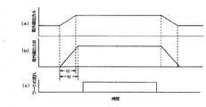
〔本形態における紫外線照射装置の動作について〕 本発明においては、点灯回路OCによる相対的大電力をショートアーク形水銀ランプSHLに投入する際の投入電力の立ち上がり開始時と、シャッター機構の開放開始時とがほぼ一致するように構成される。 [Operation of Ultraviolet Irradiation Device in the Present Embodiment] In the present invention, when the relative large power from the lighting circuit OC is input to the short arc type mercury lamp SHL, when the input power rises and when the shutter mechanism starts to open Are configured to substantially match.
以下、その動作を図7により説明する。グラフ(a)は、シャッター機構SPを通過する前のシャッター機構に到達するショートアーク形水銀ランプSHLからの紫外線出力レベルを示し、紫外線出力Aと呼ぶ。グラフ(b)は、ワーク側に到達するシャッター機構SPを通過したショートアーク形水銀ランプSHLからの紫外線出力レベルを示し、紫外線出力レベルBとよぶ。グラフ(c)は、ショートアーク形水銀ランプSHLの第1の期間T1および第2の期間T2の点灯のタイミングにおけるワークが流れているタイミングを説明している。シャッター機構SPが全閉のときはワーク側の紫外線出力Bのレベルはゼロであり、シャッター機構SPが所定の時間t2で全開されていくことにより、ワークに到達する紫外線出力Bレベルが上昇し、シャッター機構SPが全開すると、ワーク側への紫外線到達レベルは最大となる。グラフ(a)によれば、紫外線出力Aがローレベルのときは、図4における第2の期間T2を示し、図4における点灯回路OCによる相対的大電力をショートアーク形水銀ランプSHLに投入するタイミングと図7(b)におけるシャッター機構SPの開放開始時タイミングとがほぼ一致させていることが図7(a)とのタイミングの関係から分かる。すなわち、図7(a)におけるタイミングt1はショートアーク形水銀ランプSHLに第2の期間T2から第1の期間T1に切り替わる相対的大電力が印加されるタイミングを拡大して示している。これに対して、ワーク側への紫外線照射レベルが最大に到達するのはシャッター機構SPが全開するt2となる。 The operation will be described below with reference to FIG. Graph (a) shows the UV output level from the short arc mercury lamp SHL that reaches the shutter mechanism before passing through the shutter mechanism SP, and is referred to as UV output A. Graph (b) shows the ultraviolet output level from the short arc type mercury lamp SHL that has passed through the shutter mechanism SP that reaches the workpiece side, and is called the ultraviolet output level B. Graph (c) illustrates the timing at which the work flows in the lighting timings of the first period T1 and the second period T2 of the short arc mercury lamp SHL. When the shutter mechanism SP is fully closed, the level of the ultraviolet output B on the workpiece side is zero. When the shutter mechanism SP is fully opened at the predetermined time t2, the ultraviolet output B level reaching the workpiece increases. When the shutter mechanism SP is fully opened, the level of ultraviolet rays reaching the workpiece is maximized. According to the graph (a), when the ultraviolet output A is at a low level, the second period T2 in FIG. 4 is shown, and the relative large power from the lighting circuit OC in FIG. 4 is input to the short arc mercury lamp SHL. It can be seen from the timing relationship with FIG. 7A that the timing and the opening start timing of the shutter mechanism SP in FIG. That is, the timing t1 in FIG. 7A is an enlarged view of the timing at which the relative high power for switching from the second period T2 to the first period T1 is applied to the short arc type mercury lamp SHL. On the other hand, the maximum ultraviolet irradiation level on the workpiece side reaches t2 when the shutter mechanism SP is fully opened.
したがって、本発明の紫外線照射装置によれば、その動作が時間t2≧t1を満足するように構成されているので、ショートアーク形水銀放電ランプのフラッシュアップ点灯時の紫外線出力が安定した直後から紫外線照射を開始することが可能になる。 Therefore, according to the ultraviolet irradiation apparatus of the present invention, the operation is configured to satisfy the time t2 ≧ t1, so that the ultraviolet ray immediately after the ultraviolet output at the time of flash-up lighting of the short arc type mercury discharge lamp is stabilized. Irradiation can be started.
次に、本形態における光学系の作用について説明する。図1において、ショートアーク形水銀ランプSHLから放射された紫外線は、楕円反射鏡ER内において、第1焦点f1から出射して楕円反射鏡ERの反射面で反射して楕円反射鏡ERから図1において下方へ集光しながら出射する。そして、ミラーM1に入射し、反射して、第1の光軸LX1に対してほぼ90°方向に向きが変更され、さらに集光しながら導光体LGの一端付近に位置する第2焦点f2に収斂する。 Next, the operation of the optical system in this embodiment will be described. In FIG. 1, the ultraviolet rays radiated from the short arc mercury lamp SHL are emitted from the first focal point f1 in the elliptical reflector ER and reflected by the reflecting surface of the elliptical reflector ER. In FIG. The second focal point f2 is incident on the mirror M1, reflected, changed in direction to approximately 90 ° with respect to the first optical axis LX1, and further condensed and positioned near one end of the light guide LG. To converge.
第2焦点f2に収斂した紫外線は、円盤状紫外線通過量制御機構UVCすなわち調光機構DPまたは/およびシャッター機構SPを通過して導光体LG内にその一端から入射する。そして、導光体LG内を導光されて他端から出射する。出射した紫外線は、集光レンズユニットLUで再び集光され、ミラーM2で反射して図1において下方へ屈折し、照射口IROから紫外線照射装置の外部へ照射される。 The ultraviolet rays converged on the second focal point f2 pass through the disk-like ultraviolet ray passage amount control mechanism UVC, that is, the light control mechanism DP or / and the shutter mechanism SP, and enter the light guide LG from one end thereof. Then, the light is guided through the light guide LG and emitted from the other end. The emitted ultraviolet is again condenser by the condenser lens unit L U, refracted downward in FIG. 1 is reflected by the mirror M2, and is irradiated from the irradiation port IRO to the outside of the ultraviolet irradiation device.
〔その他の構成について〕 次に、本形態における副次的な構成要素について説明する。 [Other Configurations] Next, subsidiary components in the present embodiment will be described.
1.(楕円反射鏡ERについて) 楕円反射鏡ERは、第1焦点f1および第2焦点f2を有し、例えば反射面が椀形の回転楕円体形状をなしている。また、その第1焦点f1にショートアーク形水銀ランプSHLの発光中心が位置するように配置されることによって、ショートアーク形水銀ランプSHLから放射される紫外線を反射して第2焦点f2に集光する。 1. (Elliptic Reflector ER) The elliptical reflector ER has a first focal point f1 and a second focal point f2, and has a spheroidal shape with, for example, a reflective surface. Further, by arranging the light emission center of the short arc mercury lamp SHL at the first focal point f1, the ultraviolet rays radiated from the short arc mercury lamp SHL are reflected and condensed to the second focal point f2. To do.
また、楕円反射鏡ERは、好適には椀形のガラス基体の内面に紫外線反射・赤外線透過性被膜を被着させてなされる構成のものを採用することができる。そして、ショートアーク形水銀ランプSHLの発光部が内部に収納される。 Further, the elliptical reflecting mirror ER may be preferably constructed by depositing an ultraviolet reflective / infrared transparent coating on the inner surface of a bowl-shaped glass substrate. And the light emission part of short arc type mercury lamp SHL is stored in an inside.
2.(ミラーM1について) ミラーM1は、楕円反射鏡ERから出射した反射紫外線の進行方向をほぼ90°の角度で変更させる光学手段である。この反射手段には平面反射鏡を用いることができる。なお、所望によりミラーM1の傾斜角を微調整する角度調整手段を付加することができる。 2. (Regarding Mirror M1) The mirror M1 is an optical means that changes the traveling direction of the reflected ultraviolet light emitted from the elliptical reflecting mirror ER at an angle of approximately 90 °. A planar reflecting mirror can be used as the reflecting means. An angle adjusting means for finely adjusting the tilt angle of the mirror M1 can be added if desired.
また、ミラーM1は、楕円反射鏡ERの開口と第2焦点f2との間に位置して、好ましくは第2焦点f2になるべく接近した位置になるように、配設されている。 Further, the mirror M1 is disposed between the opening of the elliptical reflecting mirror ER and the second focal point f2, and is preferably disposed as close as possible to the second focal point f2.
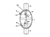
3.(調光機構DPについて) 調光機構DPは、図6に示すように、回転中心x1の周りに回転する調光板P1およびこの調光板P1を所定角度だけ節動回転させるための駆動回転を行う節動回転駆動手段(図示しな。)、例えばステッピングモータを備えている。そして、調光板P1には複数ステップの節動回転位置(例えば回転中心x1の回りの270°の間に63ステップ)がディジタル的に設定され、そのステップごとに節動させて所定のステップ位置に到達するように構成するとともに、各ステップ位置には1個または複数個の透孔からなり、開口面積がステップ数に応じて順次変化して、通過紫外線量が0〜100%を規定している開口OP1が環状に配置されている。 3. (Regarding the Dimming Mechanism DP) As shown in FIG. 6, the dimming mechanism DP is a dimming plate P1 that rotates about the rotation center x1 and a driving rotation for rotationally rotating the dimming plate P1 by a predetermined angle. This includes a rotational rotation driving means (not shown), for example, a stepping motor. The dimming plate P1 is digitally set with a plurality of stepping rotation positions (for example, 63 steps between 270 degrees around the rotation center x1), and the stepping movement is performed at each step to a predetermined step position. Each step position is composed of one or a plurality of through holes, and the opening area is sequentially changed according to the number of steps, and the passing ultraviolet ray amount is defined as 0 to 100%. The opening OP1 is annularly arranged.
そうして、本形態における調光機構DPによれば、調光板P1を節動回転駆動するとともに、予めステップ数と開口面積とを所定の関係に設定してあるので、図7に示すような直線性に優れた調光特性を得ることができる。 Then, according to the dimming mechanism DP in the present embodiment, together with the rotationally driven articulate dimming plate P1, since is set in advance the number of steps and the opening area in a predetermined relationship, as shown in FIG. 7 It is possible to obtain dimming characteristics with excellent linearity.
また、調光機構DPは、前述のシャッター機構SPとともに円盤状紫外線通過量制御機構UVCを構成している。 また、円盤状紫外線通過量制御機構UVCは、図1に示すように、楕円反射鏡ERとミラーM1とを結ぶ第1の光軸LX1に対して直角で、かつミラーM1と導光体LGとを結ぶ第2の光軸LX2を含む平面Pを挟んで反射鏡ERの反対側に回転中心x1、x2が位置する。そして、円盤部P1またはP2の作用部がミラーM1と導光体LGとの間に介在して紫外線の通過量を制御する光学制御機構である。 Further, the light control mechanism DP constitutes a disk-shaped ultraviolet light passage control mechanism UVC together with the shutter mechanism SP described above. Further, as shown in FIG. 1, the disk-shaped ultraviolet ray passage amount control mechanism UVC is perpendicular to the first optical axis LX1 connecting the elliptical reflecting mirror ER and the mirror M1, and the mirror M1 and the light guide LG. The rotation centers x1 and x2 are located on the opposite side of the reflecting mirror ER across the plane P including the second optical axis LX2 connecting the two. And the action part of disk part P1 or P2 is an optical control mechanism which interposes between the mirror M1 and the light guide LG, and controls the passage amount of an ultraviolet-ray.
したがって、本形態の円盤状紫外線通過量制御機構UVCによれば、導光体LGの他端から出射する紫外線量を制御することができる。紫外線の制御は、調光および通過・遮断の切り換え(シャッター動作)のいずれか一方または両方が可能なように構成することができる。調光を行うときには調光機構DPが、また通過・遮断の切り換え(シャッター動作)を行うときにはシャッター機構SPが、それぞれ配設される。両方を行う際には、調光機構DPの調光板P1とシャッター機構SPのシャッター板P2の作用部が近接するように配設される。 Therefore, according to the disk-shaped ultraviolet ray passage amount control mechanism UVC of this embodiment, the amount of ultraviolet rays emitted from the other end of the light guide LG can be controlled. The control of the ultraviolet rays can be configured such that either one or both of dimming and switching between passing and blocking (shutter operation) can be performed. A dimming mechanism DP is disposed when dimming, and a shutter mechanism SP is disposed when switching between pass and block (shutter operation) is performed. When both are performed, the light control plate P1 of the light control mechanism DP and the action portion of the shutter plate P2 of the shutter mechanism SP are disposed close to each other.
4.(排気機構ASについて) 紫外線照射装置から外部へ塵埃などが放散されないように排気機構ASを具備することができる。排気機構ASを排気ダクト(図示しない。)に接続すれば、紫外線照射装置内が低圧になり、内部から塵埃などの不純物が放散しなくなる。 4). (Exhaust Mechanism AS) The exhaust mechanism AS can be provided so that dust and the like are not diffused from the ultraviolet irradiation device to the outside. If the exhaust mechanism AS is connected to an exhaust duct (not shown), the inside of the ultraviolet irradiation device becomes a low pressure, and impurities such as dust are not diffused from the inside.
5.(光源位置微調整機構LXRについて) 光源位置微調整機構LXRは、ショートアーク形水銀ランプSHLの管軸位置を微調整する機構である。なお、ショートアーク形水銀ランプSHLは、後述するハウジングHの天井から吊持されている。 5. (Regarding Light Source Position Fine Adjustment Mechanism LXR) The light source position fine adjustment mechanism LXR is a mechanism for finely adjusting the tube axis position of the short arc mercury lamp SHL. The short arc type mercury lamp SHL is suspended from the ceiling of the housing H described later.
6.(ハウジングHについて) ハウジングHは、以上の各手段を内部の所定位置に収納している。 6). (Regarding the Housing H) The housing H houses the above-described means at predetermined positions inside.
以下、本発明の紫外線照射装置を実施するためのその他の形態について説明する。 Hereinafter, other embodiments for implementing the ultraviolet irradiation device of the present invention will be described.
[第2の形態]
第2の形態は、第1の形態において、フラッシュアップ点灯において、相対的大電力の投入による第1の期間における紫外線出力の立ち上がり時間t1を0.2〜2秒に設定する。
[Second form]
In the second mode, in the first mode, in flash-up lighting, the rising time t1 of the ultraviolet output in the first period due to the relatively large power input is set to 0.2 to 2 seconds.
そうして、本形態においては、上記立ち上がり時間を0.2〜2秒に設定することにより、電極物質の不所望な飛散が抑制されるので、光束維持率が向上して、長時間点灯しても紫外線照度の低下を抑制することができる。 Thus, in this embodiment, by setting the rise time to 0.2 to 2 seconds, unwanted scattering of the electrode material is suppressed, so that the luminous flux maintenance factor is improved and the lamp is lit for a long time. However, it is possible to suppress a decrease in the ultraviolet illuminance.
図1に示す第1の形態である。 It is the 1st form shown in FIG.
ショートアーク形水銀ランプ
透光性気密容器:包囲部の内径20mm
一対の電極 :電極間距離2.8mm
放電媒体 :水銀およびArガス
点灯回路(フラッシュアップ点灯を行う。)
第1の期間 :1000W
第2の期間 :700W
第1・第2の期間:それぞれ10秒間
電力立ち上がり時間:0.2秒
[比較例1]
電力立ち上がり時間:0.1秒
その他は実施例と同じ。
波長365nmの紫外線照度の相対最大値(%)は、表1に示すとおりであった。
Short arc mercury lamp Translucent airtight container: Inner diameter 20mm
Pair of electrodes: 2.8 mm distance between electrodes
Discharge medium: Mercury and Ar gas lighting circuit (performs flash-up lighting)
First period: 1000W
Second period: 700W
First and second periods: 10 seconds each Power rise time: 0.2 seconds
[Comparative Example 1]
Power rise time: 0.1 seconds Others are the same as in the example.
The relative maximum value (%) of ultraviolet illuminance at a wavelength of 365 nm was as shown in Table 1.
[表1]
点灯時間(hr) 実施例(%) 比較例(%)
0 100 100
100 95 90
500 90 80
1000 85 75
表1から理解できるように、実施例(本発明)によれば、比較例に比較してショートアーク形水銀ランプの寿命の進展に伴う紫外線照度の低下が顕著に抑制される。
[Table 1]
Lighting time (hr) Example (%) Comparative example (%)
0 100 100
100 95 90
500 90 80
1000 85 75
As can be understood from Table 1, according to the example (the present invention), a decrease in the illuminance of ultraviolet rays accompanying the progress of the life of the short arc type mercury lamp is remarkably suppressed as compared with the comparative example.
[第3の形態]
第3の形態は、第1の形態において、図1におけるハウジングHの内容積V(cm3)とし、フラッシュアップ点灯における相対的大電力のランプ電力をW(W)としたとき、数式V/W≦45を満足するように構成している。
[Third embodiment]
In the first embodiment, when the internal volume V (cm 3 ) of the housing H in FIG. 1 and the lamp power of the relatively large power in flash-up lighting is W (W) in the first embodiment, the formula V / It is configured to satisfy W ≦ 45.
そうして、本形態においては、上記数式を満足することにより、ショートアーク形水銀ランプに比較的小形のものを用いることが可能になり、ケーシングを小型化できるとともに、省電力化を図ることができる。 Thus, in the present embodiment, by satisfying the above formula, it becomes possible to use a relatively small short arc type mercury lamp, and the casing can be miniaturized and power saving can be achieved. it can.
V/W=36.3
その他は、実施例1と同じ。
[比較例2]
点灯回路 :800Wのランプ電力を連続投入する回路
V/W=45.4
その他は実施例1と同じ。
波長365nmの紫外線照度の最大値(mW/cm2)は、表2に示すとおりであった。
V / W = 36.3
Others are the same as Example 1.
[Comparative Example 2]
Lighting circuit: Circuit for continuously supplying lamp power of 800 W V / W = 45.4
Others are the same as Example 1.
The maximum value of ultraviolet illuminance at a wavelength of 365 nm (mW / cm 2 ) was as shown in Table 2.
[表2]
紫外線照度の最大値(mW/cm2)
実施例2 200
比較例2 160
表2から理解できるように、実施例2の方が比較例2より紫外線照度が大きくなる。
[Table 2]
Maximum UV illuminance (mW / cm 2 )
Example 2 200
Comparative Example 2 160
As can be understood from Table 2, the ultraviolet illuminance is higher in Example 2 than in Comparative Example 2.
次に、本形態において、ハウジングHの内容積を一定にしてランプ電力W(W)を変化させたときの紫外線照度の最大値(mW/cm2)は、表3に示すとおりであった。 Next, in this embodiment, the maximum value (mW / cm 2 ) of the ultraviolet illuminance when the lamp power W (W) was changed with the internal volume of the housing H being constant was as shown in Table 3.
[表3]
W(W) V/W 紫外線照度の最大値(mW/cm2)
700 51.8 120
800 45.4 160
1000 36.3 200
1200 30.3 240
表3から理解できるように、本形態によれば、紫外線照度の最大値が顕著に大きくなる。
[Table 3]
W (W) V / W Maximum UV illuminance (mW / cm 2 )
700 51.8 120
800 45.4 160
1000 36.3 200
1200 30.3 240
As can be understood from Table 3, according to this embodiment, the maximum value of the ultraviolet illuminance is remarkably increased.
実施例2および比較例2において、紫外線照射の露光時間を変化して紫外線硬化性樹脂Aの硬化試験を実施したときの評価結果は表4に示すとおりであった。なお、紫外線硬化性樹脂Aは、波長365nmの紫外線照度が200mW/cm2以上で硬化する。また、表中において、○は硬化した、×は硬化しない、をそれぞれ示している。 In Example 2 and Comparative Example 2, the evaluation results when the curing test of the ultraviolet curable resin A was performed while changing the exposure time of ultraviolet irradiation were as shown in Table 4. The ultraviolet curable resin A is cured when the ultraviolet illuminance at a wavelength of 365 nm is 200 mW / cm 2 or more. In the table, ◯ indicates cured, and x indicates not cured.
[表4]
露光時間(秒) 0.5 1.0 1.5 2.0
実施例2 × × ○ ○
比較例2 × × × ×
表4から理解できるように、実施例2によれば、紫外線硬化性樹脂Aの場合、露光時間が1.5秒以上であれば、紫外線硬化性樹脂Aの硬化の実用に供することができる。これに対して、比較例2では硬化が得られなかった。
[Table 4]
Exposure time (seconds) 0.5 1.0 1.5 2.0
Example 2 × × ○ ○
Comparative Example 2 × × × ×
As can be understood from Table 4, according to Example 2, in the case of the ultraviolet curable resin A, if the exposure time is 1.5 seconds or longer, the ultraviolet curable resin A can be practically used for curing. On the other hand, curing was not obtained in Comparative Example 2.
さらに、紫外線硬化性樹脂Bの硬化試験を上記と同様に実施したときの評価結果は表5に示すとおりであった。なお、紫外線硬化性樹脂Bは、波長365nmの紫外線積算光量が320mWs/cm2で硬化する。 Furthermore, the evaluation results when the curing test of the ultraviolet curable resin B was performed in the same manner as described above were as shown in Table 5. In addition, the ultraviolet curable resin B is cured at an ultraviolet integrated light quantity of wavelength 365 nm of 320 mWs / cm 2 .
[表5]
露光時間(秒) 0.5 1.0 1.4 1.6 1.8 2.0
実施例2 × × ○ ○ ○ ○
比較例2 × × × × × ○
表5から理解できるように、実施例2によれば、露光時間が1.4秒以上であれば、紫外線硬化性樹脂Bの硬化の実用に供することができる。これに対して、比較例2では2.0秒未満の時間では硬化が得られなかった。
[Table 5]
Exposure time (seconds) 0.5 1.0 1.4 1.6 1.8 2.0
Example 2 × × ○ ○ ○ ○
Comparative Example 2 × × × × × ○
As can be understood from Table 5, according to Example 2, when the exposure time is 1.4 seconds or more, the ultraviolet curable resin B can be used for practical use. On the other hand, in Comparative Example 2, curing could not be obtained in a time shorter than 2.0 seconds.
[第4の形態]
第4の形態は、ショートアーク形水銀ランプの少なくとも一方の電極、好ましくは一対の電極における軸部の外周面に直径が0.3mm以下の耐火性金属、例えばタングステン(W)の細線からなるコイルを形成した構成である。なお、コイルは、好ましくは密巻きである。
[Fourth form]
The fourth embodiment is a coil made of a thin wire of a refractory metal having a diameter of 0.3 mm or less, such as tungsten (W), on the outer peripheral surface of the shaft portion of at least one electrode of the short arc type mercury lamp, preferably a pair of electrodes. It is the structure which formed. The coil is preferably closely wound.
そうして、本形態においては、透光性気密容器の封止部に埋設されている状態で、上記コイルが封着緩衝部として作用するので、フラッシュアップ点灯でランプ電力が過入力状態になった際に、電極軸と周囲の石英ガラスとの熱膨張率差を、上記構成のコイルによって形成された空間で緩和させることができる。このため、電極封着部の信頼性が向上する。 And in this form, since the said coil acts as a sealing buffer part in the state embed | buried in the sealing part of a translucent airtight container, lamp power will be in an over-input state by flash-up lighting. In this case, the difference in thermal expansion coefficient between the electrode shaft and the surrounding quartz glass can be relaxed in the space formed by the coil having the above configuration. For this reason, the reliability of an electrode sealing part improves.
[第5の形態]
第5の形態は、ショートアーク形水銀ランプの一対の電極を陰極および陽極により構成して直流点灯を行うように構成するとともに、陽極を透光性気密容器の外部から冷却する冷却手段を配設した構成である。冷却手段は、具体構造が特段限定されるものではないが、好ましくはエアブロワーを用いるのがよい。
[Fifth embodiment]
In the fifth embodiment, a pair of electrodes of a short arc type mercury lamp is constituted by a cathode and an anode so as to perform direct current lighting, and a cooling means for cooling the anode from the outside of the translucent airtight container is provided. This is the configuration. The specific structure of the cooling means is not particularly limited, but an air blower is preferably used.
本発明においては、ショートアーク形水銀ランプをフラッシュアップ点灯するので、特に陽極の温度上昇が激しくなり、陽極周辺の封着部が強い熱ストレスに晒される。その結果、ショートアーク形水銀ランプの信頼性が低下するという問題がある。 In the present invention, since the short arc type mercury lamp is turned on in a flash-up manner, the temperature rise of the anode is particularly severe, and the sealing portion around the anode is exposed to strong thermal stress. As a result, there is a problem that the reliability of the short arc type mercury lamp is lowered.
本形態においては、陽極周辺の封着部が冷却手段により冷やされるので、陽極周辺の封着部が強い熱ストレスに晒されなくなる。このため、ショートアーク形水銀ランプの信頼性が向上する。 In this embodiment, since the sealing portion around the anode is cooled by the cooling means, the sealing portion around the anode is not exposed to strong thermal stress. For this reason, the reliability of the short arc type mercury lamp is improved.
[第6の形態]
第6の形態は、ショートアーク形水銀ランプにおける透光性気密容器の包囲部が、その肉厚体積をGV(cm3)とし、フラッシュアップ時のランプ電力をW(W)としたとき、BVおよびWが数式50<W/GV<300を満足するように構成されている。
[Sixth embodiment]
In the sixth embodiment, when the surrounding portion of the light-transmitting airtight container in the short arc type mercury lamp is GV (cm 3 ) and the lamp power at the time of flash-up is W (W), BV And W satisfy the
BVおよびWが範囲内であれば、フラッシュアップ点灯によって生じる寿命中の熱歪が図8に示すように低減する。なお、図8において、横軸はW/GVを、縦軸は歪量(MPa)を、それぞれ示す。 If BV and W are within the range, thermal strain during the lifetime caused by flash-up lighting is reduced as shown in FIG. In FIG. 8, the horizontal axis represents W / GV, and the vertical axis represents the strain amount (MPa).
このため、ショートアーク形水銀ランプの長寿命化が可能となる。また、寿命中の透光性気密容器の破裂も抑制できるので、ショートアーク形水銀ランプの信頼性が向上する。 For this reason, it is possible to extend the life of the short arc type mercury lamp. Moreover, since the bursting of the light-transmitting hermetic container during its lifetime can be suppressed, the reliability of the short arc type mercury lamp is improved.
しかし、ショートアーク形水銀ランプは、フラッシュアップ点灯により包囲部内の圧力が40〜50気圧程度になるため、W/GVが50以下になると、ショートアーク形水銀ランプが破裂しやすくなるので、不可である。また、W/GVが300以上になると、光束立ち上がり特性が悪くなるので、不可である。なぜなら、水銀蒸気は、透光性気密容器の温度に依存し、包囲部の内容積が大きくなってBVの値が上昇すると、透光性気密容器の温度上昇に要する時間が長くなるからである。 However, the short arc type mercury lamp is not possible because the pressure in the enclosure is about 40-50 atm due to flash-up lighting, and if the W / GV is 50 or less, the short arc type mercury lamp tends to burst. is there. In addition, when W / GV is 300 or more, the rise characteristic of the light beam is deteriorated, which is not possible. This is because mercury vapor depends on the temperature of the light-transmitting hermetic container, and when the inner volume of the enclosure increases and the value of BV increases, the time required to increase the temperature of the light-transmitting hermetic container becomes longer. .
[第7の形態]
第7の形態は、ショートアーク形水銀ランプにおける一対の電極の少なくとも一方の周囲を包囲する透光性気密容器の包囲部の外面に保温膜(例えば、図2における符号6を付した部分)を形成する場合に、当該保温膜の膜厚をL(mm)としたとき、Lが数式L<0.5を満足する構成である。なお、保温膜の材質の好ましい材質は、白金膜などである。
[Seventh form]
In the seventh embodiment, a heat insulating film (for example, a portion denoted by reference numeral 6 in FIG. 2) is provided on the outer surface of the surrounding portion of the translucent airtight container that surrounds at least one of the pair of electrodes in the short arc type mercury lamp. When forming, when the film thickness of the heat insulating film is L (mm), L satisfies the formula L <0.5. A preferable material for the heat insulating film is a platinum film or the like.
そうして、本態様においては、保温膜の膜厚が上記数式を満足することにより、保温性能が最適化されて、透光性気密容器の温度上昇が早くなるために、安定した動作特性を有するショートアーク形水銀ランプが得られる。 Thus, in this embodiment, when the film thickness of the heat insulating film satisfies the above formula, the heat insulating performance is optimized, and the temperature rise of the translucent airtight container is accelerated. A short arc mercury lamp having the same is obtained.
[第8の形態]
第8の形態は、ショートアーク形水銀ランプにおける透光性気密容器の内容積をVa(cm3)とし、一対の電極の少なくとも一方の周囲を包囲する透光性気密容器の包囲部の外面に保温膜(例えば、図2における符号6を付した部分)を形成する場合に、当該保温膜の体積をVb(cm3)としたとき、VaおよびVbが数式Vb/Va<0.1を満足する構成である。
[Eighth form]
In the eighth embodiment, Va (cm 3) is the inner volume of the light-transmitting hermetic container in the short arc type mercury lamp, and the outer surface of the surrounding part of the light-transmitting hermetic container surrounding at least one of the pair of electrodes is kept warm. In the case of forming a film (for example, a portion denoted by reference numeral 6 in FIG. 2), when the volume of the heat insulating film is Vb (cm 3 ), Va and Vb satisfy the formula Vb / Va <0.1. It is a configuration.
そうして、本態様においては、VaおよびVbが上記数式を満足することにより、保温性能が最適化されて、透光性気密容器の温度上昇が早くなるために、安定した動作特性を有するショートアーク形水銀ランプが得られる。 Thus, in this embodiment, since Va and Vb satisfy the above formula, the heat retention performance is optimized and the temperature rise of the translucent airtight container is accelerated, so that the short circuit having stable operating characteristics is achieved. An arc-type mercury lamp is obtained.
[第9の形態]
第9の形態は、ショートアーク形水銀ランプの一対の電極を陰極および陽極として直流点灯を行うように構成する場合において、陽極の放電スポットが形成されない位置に、ゲッターが配設されている構成である。ゲッターとしては、例えばタンタル(Ta)、ジルコニウム(Zr)、ジルコニウム−アルミニウム合金などの既知の金属の粉末を主成分とする塗布液を上記所定の位置に塗布乾燥により被着させることによって形成することができる。
[Ninth Embodiment]
The ninth form is a configuration in which a getter is disposed at a position where a discharge spot of the anode is not formed in a case where a pair of electrodes of a short arc type mercury lamp is configured to perform direct current lighting using a cathode and an anode. is there. The getter is formed, for example, by applying a coating solution containing a known metal powder such as tantalum (Ta), zirconium (Zr), zirconium-aluminum alloy or the like as a main component to the predetermined position by coating and drying. Can do.
そうして、本態様においては、ショートアーク形水銀ランプの初期および寿命中の始動不良、発光のちらつき、紫外線照度の低下を抑制することができる。特にフラッシュアップ点灯を行う場合に、過入力時でも紫外線照射装置の性能向上、コストダウンおよびショートアーク形水銀ランプの信頼性向上を確保することができる。 Thus, in this embodiment, it is possible to suppress the start-up failure, flickering of light emission, and decrease in ultraviolet illuminance during the initial and lifetime of the short arc type mercury lamp. In particular, when performing flash-up lighting, it is possible to ensure improved performance of the ultraviolet irradiation device, cost reduction, and improved reliability of the short arc type mercury lamp even when the input is excessive.
[第10の形態]
第10の形態は、ショートアーク形水銀ランプの一対の電極を陰極および陽極として直流を行うように構成する場合において、図9に示すように、透光性気密容器の陰極側の封止部の管軸方向の長さをL1とし、当該封止部に装着する口金の封止部に対向する部分の長さをL2としたとき、L1およびL2が数式1.5≦L1/L2≦5を満足する構成である。なお、口金は、金属製である。また、図9において、図2と同一部分については同一符号を付して説明は省略する。
[Tenth embodiment]
In the tenth embodiment, in the case where direct current is performed using a pair of electrodes of a short arc type mercury lamp as a cathode and an anode, as shown in FIG. 9, the sealing portion on the cathode side of the translucent airtight container is When the length in the tube axis direction is L1, and the length of the portion facing the sealing portion of the base attached to the sealing portion is L2, L1 and L2 satisfy the formula 1.5 ≦ L1 / L2 ≦ 5. It is a satisfactory configuration. The base is made of metal. Also, in FIG. 9, the same parts as those in FIG.
そうして、本態様においては、上記数式を満足することにより、ショートアーク形水銀ランプを消灯した後に、電極表面に水銀が付着しにくくなる。その結果、再点灯時の絶縁破壊電圧が低下し、放電スポットが安定し、始動性不良などの不具合発生を抑制することができる。なお、水銀が電極に付着すると、次回点灯時の始動電圧(Vs)上昇や始動不良の発生を抑制することができる。 And in this aspect, by satisfy | filling the said numerical formula, after turning off a short arc type mercury lamp, mercury becomes difficult to adhere to the electrode surface. As a result, the dielectric breakdown voltage at the time of relighting is reduced, the discharge spot is stabilized, and the occurrence of problems such as poor startability can be suppressed. In addition, when mercury adheres to the electrode, it is possible to suppress the start voltage (Vs) rise and the start failure at the next lighting.
[第11の形態]
第11の形態は、ショートアーク形水銀ランプの一対の電極を陰極および陽極として直流を行うように構成する場合において、図2に示す保温膜5の管軸方向の長さをL3(mm)としたとき、L3が数式L3>3を満足する構成である。なお、保温膜の材質の好ましい材質は、白金膜などである。
[Eleventh form]
In the eleventh embodiment, when the direct current is performed using a pair of electrodes of a short arc type mercury lamp as a cathode and an anode, the length of the
そうして、本態様においては、上記数式を満足することにより、ショートアーク形水銀ランプを消灯した後に、電極表面に水銀が付着しにくくなる。その結果、再点灯時の絶縁破壊電圧が低下し、放電スポットが安定し、始動性不良などの不具合発生を抑制することができる。なお、水銀が電極に付着すると、次回点灯時の始動電圧(Vs)上昇や始動不良の発生を抑制することができる。 And in this aspect, by satisfy | filling the said numerical formula, after turning off a short arc type mercury lamp, mercury becomes difficult to adhere to the electrode surface. As a result, the dielectric breakdown voltage at the time of relighting is reduced, the discharge spot is stabilized, and the occurrence of problems such as poor startability can be suppressed. In addition, when mercury adheres to the electrode, it is possible to suppress the start voltage (Vs) rise and the start failure at the next lighting.
[第12の形態]
第12の形態は、ショートアーク形水銀ランプの一対の電極を陰極および陽極として直流を行うように構成する場合において、図10の概念的断面図に示すように、以下の位置の少なくとも1箇所に保温膜を形成した構成である。なお、保温膜の材質の好ましい材質は、白金膜などである。また、図10において、図2と同一部分については同一符号を付して説明は省略する。
[Twelfth embodiment]
In the twelfth embodiment, when a direct current is formed using a pair of electrodes of a short arc type mercury lamp as a cathode and an anode, as shown in a conceptual cross-sectional view of FIG. In this configuration, a heat insulating film is formed. A preferable material for the heat insulating film is a platinum film or the like. In FIG. 10, the same parts as those in FIG.
(1)陰極の先端からその基端に向かって1mm離れた点K1から管軸に直角に引いた直線と包囲部の外面との交点の位置から陰極側の包囲部端部までの第1の外面領域に保温膜6aを形成する。
(1) First from the position of the intersection of a straight line drawn perpendicularly to the tube axis from the
(2)陽極の先端からその基端に向かって1mm離れた点K2から管軸に直角に引いた直線と包囲部の外面との交点の位置から陽極側の包囲部端部までの第2の外面領域に保温膜6bを形成する。
(2) Second from the position of the intersection of the straight line drawn perpendicularly to the tube axis from the
(3)包囲部の側面から突出する排気チップオフ部1a1の外面に保温膜6cを形成する。
(3) The
(4)図2において、一対の封止部1b、1bの少なくとも一方、例えば陰極側の封止部1bに保温膜5を形成する。
(4) In FIG. 2, the
そうして、本態様においては、上記構成を備えていることにより、ショートアーク形水銀ランプの透光性気密容器の温度上昇が早くなり、安定した動作特性を有するショートアーク形水銀ランプを得ることができる。 Thus, in this aspect, by providing the above-described configuration, the temperature rise of the translucent airtight container of the short arc type mercury lamp is accelerated, and a short arc type mercury lamp having stable operating characteristics is obtained. Can do.
[第13の形態]
第13の形態は、ショートアーク形水銀ランプと、相対的大電力を供給してショートアーク形水銀ランプをフラッシュアップ点灯する第1の期間と相対的小電力を供給してショートアーク形水銀ランプの放電を持続させて待機点灯する第2の期間を交互に繰り返えす点灯回路と、開閉動作を行ってショートアーク形水銀ランプから発生した紫外線を通過または遮断するシャッター機構と、シャッター機構を通過した紫外線をワークに照射する紫外線照射部と、を具備し、図11の(a)に示すように第1の期間における相対的大電力の投入による紫外線出力Aが立ち上がった後に、図11の(d)に示すようにシャッター開放動作が開始し、図11の(b)に示すように紫外線出力Bの照射が開始するように構成されている紫外線照射装置である。
[13th form]
The thirteenth mode is a short arc type mercury lamp, a first period in which the short arc type mercury lamp is supplied with relatively high power to flash up the short arc type mercury lamp, and a relatively small power is supplied to supply the short arc type mercury lamp. A lighting circuit that alternately repeats the second period of standby lighting while sustaining discharge, a shutter mechanism that opens and closes and passes or blocks ultraviolet rays generated from a short arc mercury lamp, and passes through the shutter mechanism An ultraviolet irradiation unit for irradiating the workpiece with ultraviolet rays. As shown in FIG. 11A, after the ultraviolet output A due to the input of a relatively large power in the first period rises, ), The shutter opening operation is started, and the irradiation of the ultraviolet output B is started as shown in FIG. 11B. That.
好ましくは、図11の(c)に示すように、シャッター機構を通過する紫外線が立ち上がった後にワークが紫外線照射位置に流れるように構成される。また、相対的大電力の投入による紫外線出力が立ち上がった後にシャッター機構が開放されるように構成される。 Preferably, as shown in FIG. 11C, the work flows to the ultraviolet irradiation position after the ultraviolet rays passing through the shutter mechanism rise. In addition, the shutter mechanism is configured to be opened after the ultraviolet output from the relatively large power input is raised.
そうして、本形態においては、常に安定した紫外線照射を行うことができる。なお、図中、図7と同一部分については同一符号を付して説明は省略する。 Thus, in this embodiment, stable ultraviolet irradiation can always be performed. In the figure, the same parts as those in FIG.
[第14の形態]
第14の形態は、紫外線照射に代えて可視光を照射する可視光照射モードを選択可能に具備しているとともに、当該可視光照射モード時にはショートアーク形水銀ランプを待機点灯させるように構成されていることを特徴とする。
[14th form]
The fourteenth embodiment is configured to be able to select a visible light irradiation mode for irradiating visible light instead of ultraviolet irradiation, and is configured to turn on a short arc type mercury lamp in standby mode in the visible light irradiation mode. It is characterized by being.
すなわち、紫外線照射を行って所定の処理を行う場合、ワークに対する紫外線照射エリアの位置決めを行う際に、紫外線に代えて可視光照射を行えるようにすると便利である。可視光照射を行うためには、ショートアーク形水銀ランプから発生する紫外線を可視光に変換する。これを行うために、可視光変換フィルタを用いる。 That is, when performing predetermined processing by performing ultraviolet irradiation, it is convenient to perform visible light irradiation instead of ultraviolet light when positioning the ultraviolet irradiation area with respect to the workpiece. In order to perform visible light irradiation, ultraviolet rays generated from a short arc type mercury lamp are converted into visible light. In order to do this, a visible light conversion filter is used.
第14の形態においては、可視光照射を行う際にショートアーク形水銀ランプを待機点灯させるので、このときに発生する紫外線強度を相対的に低減した状態とすることができる。そして、可視光変換フィルタを用いて発生した紫外線を可視光に変換してから照射する。このときの可視光照射を利用すれば、目視によりワークなどに対する紫外線照射位置を決めることが可能になる。 In the fourteenth embodiment, the short arc mercury lamp is lit on standby when performing visible light irradiation, so that the intensity of ultraviolet rays generated at this time can be relatively reduced. Then, the ultraviolet light generated using the visible light conversion filter is converted into visible light and then irradiated. If the visible light irradiation at this time is utilized, it becomes possible to determine the ultraviolet irradiation position with respect to a workpiece | work etc. by visual observation.
次に、図12および図13を参照して第14の形態をさらに詳述する。 Next, the fourteenth embodiment will be described in further detail with reference to FIGS.
図12は、本発明の紫外線照射装置を実施するための第14の形態における調光板を示す正面図である。なお、調光板P1自体の構造は図6におけるのとほぼ同じであるが、第14の形態において関係する部位および各光照射モード時の回動位置の説明を付記してある。 FIG. 12: is a front view which shows the light control board in the 14th form for implementing the ultraviolet irradiation device of this invention. The structure of the dimming plate P1 itself is substantially the same as that in FIG. 6, but the description of the part concerned in the fourteenth embodiment and the rotation position in each light irradiation mode is added.
すなわち、調光板P1は、UV(紫外線)照射量を調節するために、それぞれの回動照射位置において開口率が変化するように配設された1個または複数個の開口OP1を有していることについては既述のとおりであるが、調光板P1の例えば矢印で示されているUV100%の紫外線照射モード時の位置には、大きな開口が1個配置されている。また、UV50%の同様位置には、開口OP1が複数配置されて、その位置の開口率50%になっている。これに対して、UV0%の同様位置には、開口が配置されていない。このため、紫外線は調光板P1によって完全に遮断される。
That is, the light control plate P1 has one or a plurality of openings OP1 arranged so that the aperture ratio changes at each rotational irradiation position in order to adjust the UV (ultraviolet) irradiation amount. As described above, one large opening is arranged at a position of the light control plate P1 in the UV irradiation mode of 100% UV indicated by an arrow, for example. Further, a plurality of openings OP1 are arranged at the same position of
一方、調光板P1の可視光照射位置は、UV100%位置におけると同様に大きな開口が1個配置されているが、これに加えて上記開口には可視光変換フィルタFが装着されている。可視光変換フィルタFは、そこに入射する紫外線を可視光に変換するように構成されているもので、既知のこの種フィルタを用いることができる。
On the other hand, the visible light irradiation position of the light control plate P1 is one large opening as in the
したがって、可視光照射モードのときには、調光板P1をステッピングモータにより所定位置に回動させる。このとき、調光板P1の可視光照射位置が図1の第2の光軸LX2に交差する位置となる。このため、ショートアーク形水銀ランプSHLから発生し、楕円反射鏡ERで集光された紫外線が可視光変換フィルタFに入射するので、可視光に変換されて出射する。出射した可視光は、図1において導光体LGおよびミラーM2を経由して紫外線が照射されるときと同様にワークの位置を照射する。 Therefore, in the visible light irradiation mode, the light control plate P1 is rotated to a predetermined position by the stepping motor. At this time, the visible light irradiation position of the light control plate P1 is a position that intersects the second optical axis LX2 in FIG. For this reason, since the ultraviolet rays generated from the short arc mercury lamp SHL and condensed by the elliptical reflector ER enter the visible light conversion filter F, they are converted into visible light and emitted. The emitted visible light irradiates the position of the workpiece in the same manner as when ultraviolet rays are irradiated via the light guide LG and the mirror M2 in FIG.
次に、光照射モードと入力電力状態およびシャッター状態との関係を図13を参照して説明する。 Next, the relationship between the light irradiation mode, the input power state, and the shutter state will be described with reference to FIG.
図13は、本発明の第13の形態における光照射モードと入力電力状態およびシャッター状態との関係を示す説明図である。図において、左側の上から下へ光照射モード、シャッター状態および入力電力状態を示し、左側から右側へ各光照射モード時すなわち可視光、UV100%、UV50%およびUV0%時を示している。
FIG. 13 is an explanatory diagram showing the relationship between the light irradiation mode, the input power state, and the shutter state in the thirteenth embodiment of the present invention. In the figure, the light irradiation mode, the shutter state and the input power state are shown from the top to the bottom on the left side, and the respective light irradiation modes, that is, visible light,
まず、シャッター状態について説明する。各光照射モード時において、図1のシャッター機構SPはそれぞれ開閉動作を行う。すなわち、開放時と閉鎖時がある。 First, the shutter state will be described. In each light irradiation mode, the shutter mechanism SP of FIG. That is, there are open time and closed time.
次に、入力電力状態について説明する。入力電力は、各光照射モード時において、フラッシュアップ点灯時に相対的に高レベルとなり、待機点灯時に相対的に低レベルとなる。 Next, the input power state will be described. In each light irradiation mode, the input power is relatively high when the flash is turned on, and relatively low when the standby is lit.
したがって、UV100%、UV50%およびUV0%時には、フラッシュアップ点灯と待機点灯とを交互に繰り返すので、フラッシュアップ点灯時に間欠的にUV照射を行う。これに対して、可視光照射時には、入力電力が低レベルの待機点灯状態に維持される。
Accordingly, when UV is 100%,
そうして、第14の形態によれば、可視光照射時には待機点灯状態に維持されるため、紫外線量の発生が低減しているので、紫外線−可視光変換を行う可視光変換フィルタFの劣化を抑制することができる。 Thus, according to the fourteenth embodiment, since the standby lighting state is maintained at the time of visible light irradiation, the generation of the amount of ultraviolet rays is reduced, so that the degradation of the visible light conversion filter F that performs ultraviolet-visible light conversion is deteriorated. Can be suppressed.
[第15の形態]
第15の形態は、ショートアーク形水銀ランプのフラッシュアップ点灯時に電力レベル変化を監視するモニタ機能を備えていることを特徴とする。
[15th form]
The fifteenth embodiment is characterized in that it has a monitor function for monitoring a power level change at the time of flash-up lighting of a short arc type mercury lamp.
すなわち、フラッシュアップ点灯を行って紫外線照射を行う場合、フラッシュアップ時と待機点灯時とでランプ電力の増減制御を繰り返しながら紫外線照射を行うので、何らかのエラーによってフラッシュアップ時に所要のランプ電力が投入されない状態が発生すると、ワークに対する紫外線照射処理に不良を生じることになる。このような事態の発生は、速やかに検知し、対処しなければならない。 In other words, when performing UV irradiation with flash-up lighting, UV irradiation is performed while repeating the increase / decrease control of lamp power during flash-up and standby lighting, so the required lamp power is not input at the time of flash-up due to some error When the state occurs, a defect occurs in the ultraviolet irradiation process for the workpiece. The occurrence of such a situation must be detected and dealt with promptly.
第15の形態においてモニタ機能として、ショートアーク形水銀ランプのフラッシュアップ点灯時にランプ電力の投入が増加するので、その変化を電気的に直接または間接的に監視すれば、フラッシュアップ点灯が適正に行われているか検知することができる。ランプ電力の変化を直接監視するには、入力電力を検出すればよい。また、ランプ電力の変化を間接的に監視するには、電圧または電流を検出すればよい。ランプ電力が上記のように変化する際の電圧または電流の変化パターンを予め調べておけば、電圧または電流の変化パターンからランプ電力の検知されるべき変化を知ることができる。 In the fifteenth embodiment, as the monitoring function, the input of lamp power increases when the short arc type mercury lamp is lit up. Therefore, if the change is electrically monitored directly or indirectly, the flash-up lighting is properly performed. It can be detected. In order to directly monitor changes in lamp power, input power may be detected. Moreover, what is necessary is just to detect a voltage or an electric current, in order to monitor the change of lamp electric power indirectly. If the change pattern of the voltage or current when the lamp power changes as described above is examined in advance, the change to be detected of the lamp power can be known from the change pattern of the voltage or current.
フラッシュアップ時に所要のランプ電力が投入されない状態が発生したときに、これを速やかに検知したら、人間系により対処することもできるが、好ましくはショートアーク形水銀ランプの点灯回路の制御回路にエラー対応システムとして組み込むのがよい。なお、エラー対応としては、エラー表示や紫外線照射動作の自動停止などを行うことができる。 If a situation occurs in which the required lamp power is not turned on at the time of flash-up, it can be dealt with by the human system if it is detected quickly, but it is preferable to handle errors in the control circuit of the lighting circuit of the short arc mercury lamp. It is good to incorporate as a system. As error handling, error display, automatic stop of ultraviolet irradiation operation, and the like can be performed.
次に、図14および図15を参照して第15の形態をさらに詳述する。 Next, the fifteenth embodiment will be described in further detail with reference to FIGS.
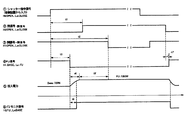
図14は、本発明の紫外線照射装置を実施するための第15の形態における制御ブロックを示す正面図である。図14に示す本発明の第15の形態において、制御ブロックは、外部、電源ユニットおよびランプハウスに区分されている。 FIG. 14: is a front view which shows the control block in the 15th form for implementing the ultraviolet irradiation device of this invention. In the fifteenth embodiment of the present invention shown in FIG. 14, the control block is divided into the outside, the power supply unit, and the lamp house.
上記外部は、紫外線照射装置に対して外部に位置する制御の上位側であり、紫外線照射装置を採用する客側の装置により構成されている。したがって、外部から紫外線照射装置の照射動作開始に対する指令であるところの(1)シャッター指令信号を送出する(なお、制御信号の前に付された数字は、図中○で囲んだ数字により示されている。以下、同様である。)。 The outside is a higher-order side of the control located outside the ultraviolet irradiation device, and is configured by a customer side device that employs the ultraviolet irradiation device. Accordingly, (1) a shutter command signal that is a command for starting the irradiation operation of the ultraviolet irradiation device is sent from the outside (note that the numbers given in front of the control signals are indicated by the numbers surrounded by circles in the figure). The same applies hereinafter.)
上記外部に対して、電源ユニットおよびランプハウスは、本発明の紫外線照射装置の制御に関係する部分を構成している。電源ユニットは、ショートアーク形水銀ランプの点灯装置であり、電子安定器および制御回路を備えて構成されている。なお、電子安定器は、ランプハウス内のランプ(ショートアーク形水銀ランプ)を点灯する点灯回路であり、電子回路を主体として構成されている。また、制御回路は、紫外線照射装置全体の制御を司り、したがって電子安定器の制御およびランプハウス内に配設される各種機器の制御を行う。 With respect to the outside, the power supply unit and the lamp house constitute a part related to the control of the ultraviolet irradiation device of the present invention. The power supply unit is a lighting device for a short arc type mercury lamp, and includes an electronic ballast and a control circuit. The electronic ballast is a lighting circuit for lighting a lamp (short arc type mercury lamp) in a lamp house, and is mainly composed of an electronic circuit. The control circuit controls the entire ultraviolet irradiation apparatus, and therefore controls the electronic ballast and various devices arranged in the lamp house.
ランプハウスは、その内部にランプ(ショートアーク形水銀ランプSHL)、イグナイタ、シャッター(シャッター機構SP)、ステッピングモータ、閉センサおよび開センサが配設されている。なお、上記において、符号は図1に示す第1の形態におけるのと共通している。 The lamp house includes a lamp (short arc type mercury lamp SHL), an igniter, a shutter (shutter mechanism SP), a stepping motor, a close sensor, and an open sensor. In addition, in the above, the code | symbol is common in the 1st form shown in FIG.
そうして、上記制御回路は、シャッターを開閉させるためにステッピングモータを制御する「シャッター開閉」を行うとともに、実際のシャッター開閉を閉センサおよび開センサからの検出信号を受信する「閉検出」および「開検出」を行って、客側装置に対して「(2)閉信号」および「(3)開信号」を送出する。また、「電子安定器に対するフラッシュアップ点灯の指令信号である「(4)FU信号」送出を行うとともに、電子安定器から第15の形態における特徴的構成である「(5)FUモニタ信号」を受信する。 Thus, the control circuit performs “shutter opening / closing” for controlling the stepping motor to open / close the shutter, and “close detection” for receiving the detection signal from the closing sensor and the opening sensor for the actual shutter opening / closing. “Open detection” is performed, and “(2) close signal” and “(3) open signal” are sent to the customer side device. In addition, “(4) FU signal, which is a command signal for flash-up lighting to the electronic ballast” is transmitted, and “(5) FU monitor signal” which is a characteristic configuration in the fifteenth embodiment is transmitted from the electronic ballast. Receive.
次に、図15を参照して上述の各制御のタイミングについて説明する。 Next, the timing of each control described above will be described with reference to FIG.
図15は、本発明の紫外線照射装置を実施するための第15の形態における制御のタイミングチャートである。 FIG. 15 is a control timing chart in the fifteenth embodiment for carrying out the ultraviolet irradiation device of the present invention.
客側装置から電源ユニットの制御回路にシャッター開(高レベル)の「(1)シャッター指令信号」が入力すると、制御回路はステッピングモータを作動させ、シャッターを開にする。 When the shutter opening (high level) “(1) shutter command signal” is input from the customer side device to the control circuit of the power supply unit, the control circuit operates the stepping motor to open the shutter.
「(1)シャッター指令信号」の立ち上がり後、時間t1でシャッターが開きだして閉センサがOPEN(開)すると、制御回路から高レベルのシャッターの「(2)閉信号」が客側装置へ送出される。また、同様に時間t2後にシャッターが開放されて開センサがCLOSE(閉)すると、制御回路からシャッターの「(3)開信号」が客側装置へ送出される。 When the shutter starts to open at time t1 after the rise of “(1) Shutter command signal” and the close sensor is opened (OPEN), the control circuit sends “(2) Close signal” of the high-level shutter to the customer side device. Is done. Similarly, when the shutter is opened after time t2 and the open sensor is closed, a “(3) open signal” of the shutter is sent from the control circuit to the customer side device.
一方、制御回路は、「(1)シャッター指令信号」立ち上がり後、時間t3に「(4)FU信号」を電子安定器へ送出する。その結果、電子安定器は、ショートアーク形水銀ランプのフラッシュアップ点灯を開始させる。 On the other hand, the control circuit sends “(4) FU signal” to the electronic ballast at time t3 after “(1) shutter command signal” rises. As a result, the electronic ballast starts flash-up lighting of the short arc type mercury lamp.
フラッシュアップ点灯が開始すると、電子安定器からショートアーク形水銀ランプへの投入電力が増大する。なお、一例として、フラッシュアップ点灯時には1000Wが投入され、待機点灯時には700Wが投入される。 When flash-up lighting starts, the input power from the electronic ballast to the short arc type mercury lamp increases. As an example, 1000 W is turned on when the flash-up is turned on, and 700 W is turned on when the light is on standby.
ショートアーク形水銀ランプへの投入電力が増大しだしてから時間t6後に、「(5)FUモニタ信号」が出力される。 "(5) FU monitor signal" is output at time t6 after the input power to the short arc type mercury lamp starts to increase.
制御回路は、「(5)FUモニタ信号」が所定タイミングで入力されないときにはエラーと判断するように構成されている。 The control circuit is configured to determine an error when “(5) FU monitor signal” is not input at a predetermined timing.
そうして、「(1)シャッター指令信号」が低レベルになってオフすると、シャッターが閉じるとともに、フラッシュアップ点灯状態が終了する。このとき、「(4)FU信号」は、シャッターが完全に閉まって「(2)開信号」が送出されてから時間t7後にオフされる。 Then, when “(1) shutter command signal” becomes low level and turns off, the shutter is closed and the flash-up lighting state is ended. At this time, “(4) FU signal” is turned off at time t7 after the shutter is completely closed and “(2) open signal” is transmitted.
本発明は、半導体露光、紫外線硬化性樹脂の硬化、光洗浄など紫外線を照射して行う処理に適用することができる。 The present invention can be applied to processing performed by irradiating with ultraviolet rays, such as semiconductor exposure, curing of an ultraviolet curable resin, and light washing.
D…開口の直径、DP…調光機構、ER…楕円反射鏡、L…距離、LG…導光体、LX1…第1の光軸、LX2…第2の光軸、M1、M2…ミラー、P1…調光板、P2…シャッター板、SHL…ショートアーク形水銀ランプ、SP…シャッター機構、UVC…円盤状紫外線通過量制御機構 D: Diameter of the opening, DP: Dimming mechanism, ER: Elliptical reflector, L: Distance, LG: Light guide, LX1: First optical axis, LX2: Second optical axis, M1, M2: Mirror, P1 ... Light control plate, P2 ... Shutter plate, SHL ... Short arc type mercury lamp, SP ... Shutter mechanism, UVC ... Disc-shaped ultraviolet ray passage control mechanism
Claims (1)
相対的大電力を供給してショートアーク形水銀ランプをフラッシュアップ点灯する第1の期間と相対的小電力を供給してショートアーク形水銀ランプの放電を持続させて待機点灯する第2の期間を交互に繰り返す点灯回路と;
開閉動作を行ってショートアーク形水銀ランプから発生した紫外線を通過または遮断するシャッター機構と;
シャッター機構を通過した紫外線をワークに照射する紫外線照射部と;
を具備し、点灯回路における相対的大電力の投入立ち上がり開始時とシャッター機構の開放開始時とがほぼ一致するとともに、第1の期間における相対的大電力の投入による紫外線出力の立ち上がり時間をt1とし、シャッター機構の閉鎖状態から開放までのシャッター機構を通過する紫外線出力の立ち上がり時間をt2としたとき、時間t1およびt2が数式t2≧t1を満足するように構成され、
フラッシュアップ点灯における光量立ち上がり時間を、0.2〜2.0秒に設定したことを特徴とする紫外線照射装置。 A short arc mercury lamp;
A first period in which the short arc type mercury lamp is flashed up by supplying a relatively large electric power and a second period in which the short arc type mercury lamp is continuously discharged and supplied with a relatively small electric power. a lighting circuit to repeat alternately;
A shutter mechanism that opens and closes to pass or block ultraviolet rays generated from the short arc mercury lamp;
An ultraviolet irradiation unit that irradiates the workpiece with ultraviolet rays that have passed through the shutter mechanism;
And the start-up start time of the relatively large power in the lighting circuit substantially coincides with the start time of the opening of the shutter mechanism, and the rising time of the ultraviolet output by the relatively high power input in the first period is t1. The time t1 and t2 are configured such that the time t1 and t2 satisfy the formula t2 ≧ t1, where t2 is the rising time of the ultraviolet output that passes through the shutter mechanism from the closed state to the open state of the shutter mechanism.
An ultraviolet irradiation device characterized in that a light amount rise time in flash-up lighting is set to 0.2 to 2.0 seconds .
Priority Applications (1)
| Application Number | Priority Date | Filing Date | Title |
|---|---|---|---|
| JP2006230080A JP4897397B2 (en) | 2005-12-27 | 2006-08-28 | UV irradiation equipment |
Applications Claiming Priority (3)
| Application Number | Priority Date | Filing Date | Title |
|---|---|---|---|
| JP2005376285 | 2005-12-27 | ||
| JP2005376285 | 2005-12-27 | ||
| JP2006230080A JP4897397B2 (en) | 2005-12-27 | 2006-08-28 | UV irradiation equipment |
Publications (2)
| Publication Number | Publication Date |
|---|---|
| JP2007201410A JP2007201410A (en) | 2007-08-09 |
| JP4897397B2 true JP4897397B2 (en) | 2012-03-14 |
Family
ID=38455635
Family Applications (1)
| Application Number | Title | Priority Date | Filing Date |
|---|---|---|---|
| JP2006230080A Expired - Fee Related JP4897397B2 (en) | 2005-12-27 | 2006-08-28 | UV irradiation equipment |
Country Status (1)
| Country | Link |
|---|---|
| JP (1) | JP4897397B2 (en) |
Families Citing this family (2)
| Publication number | Priority date | Publication date | Assignee | Title |
|---|---|---|---|---|
| JP2007180229A (en) * | 2005-12-27 | 2007-07-12 | Harison Toshiba Lighting Corp | UV irradiation equipment |
| WO2008016110A1 (en) | 2006-08-04 | 2008-02-07 | Mitsubishi Chemical Corporation | Insulating layer, electronic device, field effect transistor, and polyvinylthiophenol |
Family Cites Families (9)
| Publication number | Priority date | Publication date | Assignee | Title |
|---|---|---|---|---|
| JPS6059733A (en) * | 1983-09-13 | 1985-04-06 | Ushio Inc | Device for exposing semiconductor |
| JPS6120324A (en) * | 1984-07-07 | 1986-01-29 | Ushio Inc | Method for exposing material of semiconductor wafer by mercury lamp |
| JPS61189636A (en) * | 1985-02-19 | 1986-08-23 | Ushio Inc | Exposure method for semiconductor wafer with xenon-mercury vapor discharge lamp |
| JPH03274648A (en) * | 1990-03-23 | 1991-12-05 | Ushio Inc | Short arc-type mercury vapor discharge lamp |
| JPH0547625A (en) * | 1991-08-09 | 1993-02-26 | Nikon Corp | Projection exposure device |
| JPH11135419A (en) * | 1997-10-30 | 1999-05-21 | Nikon Corp | Scanning exposure equipment |
| JP2000181075A (en) * | 1998-12-11 | 2000-06-30 | Ushio Inc | Lamp lighting control method in exposure apparatus |
| JP3738678B2 (en) * | 2000-08-04 | 2006-01-25 | ウシオ電機株式会社 | Lamp unit for projector and dimming method thereof |
| JP2004056086A (en) * | 2002-05-31 | 2004-02-19 | Ushio Inc | Lamp lighting control device and light irradiation device |
-
2006
- 2006-08-28 JP JP2006230080A patent/JP4897397B2/en not_active Expired - Fee Related
Also Published As
| Publication number | Publication date |
|---|---|
| JP2007201410A (en) | 2007-08-09 |
Similar Documents
| Publication | Publication Date | Title |
|---|---|---|
| JP4134793B2 (en) | Light source device | |
| WO2007052770A1 (en) | Method of lighting high pressure mercury lamp, lighting device for the same, lamp system and projection display unit | |
| CN101255973A (en) | optical device | |
| CN1599023A (en) | Microwave powered lamp with reliable detection of burned out light bulbs | |
| JP4897397B2 (en) | UV irradiation equipment | |
| JP4022559B2 (en) | High pressure discharge lamp, lighting method and apparatus for high pressure discharge lamp, high pressure discharge lamp device, lamp unit, image display device, headlight device | |
| JP5092914B2 (en) | Light irradiation device | |
| WO2000046836A1 (en) | High-pressure mercury vapor discharge lamp and lamp unit | |
| JP5136949B2 (en) | Light irradiation device | |
| JP2005243797A (en) | Light energy irradiation device | |
| JP4872224B2 (en) | Luminaire equipped with the same electrodeless discharge lamp | |
| JP2006344383A (en) | Light irradiation device | |
| JPWO2009019978A1 (en) | Discharge lamp | |
| JP4783363B2 (en) | High pressure discharge lamp, lamp unit and image display device | |
| KR100840798B1 (en) | Short arc type discharge lamp lighting device, ultraviolet light irradiation device and ultraviolet light irradiation method | |
| JP4179394B2 (en) | Light source device | |
| JP2012174807A (en) | Ultraviolet irradiation device | |
| JP7278596B2 (en) | How to light the lamp | |
| JP2011154876A (en) | High-pressure discharge lamp and lighting system | |
| JP2007180229A (en) | UV irradiation equipment | |
| JP2008077908A (en) | Short arc type mercury lamp device and ultraviolet irradiation device | |
| JP2007026675A (en) | Light irradiation device, lamp for light irradiation device, and light irradiation method | |
| CN1993007B (en) | Short-arc discharge lamp lighting device, ultraviolet irradiation device, and ultraviolet irradiation method | |
| JP2008077907A (en) | Short arc discharge lamp lighting device and lighting device | |
| JP2008221193A (en) | UV irradiation equipment |
Legal Events
| Date | Code | Title | Description |
|---|---|---|---|
| A621 | Written request for application examination |
Free format text: JAPANESE INTERMEDIATE CODE: A621 Effective date: 20090819 |
|
| RD02 | Notification of acceptance of power of attorney |
Free format text: JAPANESE INTERMEDIATE CODE: A7422 Effective date: 20090819 |
|
| A521 | Written amendment |
Free format text: JAPANESE INTERMEDIATE CODE: A821 Effective date: 20090820 |
|
| A977 | Report on retrieval |
Free format text: JAPANESE INTERMEDIATE CODE: A971007 Effective date: 20110929 |
|
| A131 | Notification of reasons for refusal |
Free format text: JAPANESE INTERMEDIATE CODE: A131 Effective date: 20111011 |
|
| A521 | Written amendment |
Free format text: JAPANESE INTERMEDIATE CODE: A523 Effective date: 20111201 |
|
| TRDD | Decision of grant or rejection written | ||
| A01 | Written decision to grant a patent or to grant a registration (utility model) |
Free format text: JAPANESE INTERMEDIATE CODE: A01 Effective date: 20111220 |
|
| A01 | Written decision to grant a patent or to grant a registration (utility model) |
Free format text: JAPANESE INTERMEDIATE CODE: A01 |
|
| A61 | First payment of annual fees (during grant procedure) |
Free format text: JAPANESE INTERMEDIATE CODE: A61 Effective date: 20111222 |
|
| R150 | Certificate of patent or registration of utility model |
Ref document number: 4897397 Country of ref document: JP Free format text: JAPANESE INTERMEDIATE CODE: R150 Free format text: JAPANESE INTERMEDIATE CODE: R150 |
|
| FPAY | Renewal fee payment (event date is renewal date of database) |
Free format text: PAYMENT UNTIL: 20150106 Year of fee payment: 3 |
|
| LAPS | Cancellation because of no payment of annual fees |