JP4893004B2 - projector - Google Patents
projector Download PDFInfo
- Publication number
- JP4893004B2 JP4893004B2 JP2006029343A JP2006029343A JP4893004B2 JP 4893004 B2 JP4893004 B2 JP 4893004B2 JP 2006029343 A JP2006029343 A JP 2006029343A JP 2006029343 A JP2006029343 A JP 2006029343A JP 4893004 B2 JP4893004 B2 JP 4893004B2
- Authority
- JP
- Japan
- Prior art keywords
- light
- optical path
- optical
- illumination light
- optical element
- Prior art date
- Legal status (The legal status is an assumption and is not a legal conclusion. Google has not performed a legal analysis and makes no representation as to the accuracy of the status listed.)
- Expired - Fee Related
Links
Images


Classifications
-
- G—PHYSICS
- G03—PHOTOGRAPHY; CINEMATOGRAPHY; ANALOGOUS TECHNIQUES USING WAVES OTHER THAN OPTICAL WAVES; ELECTROGRAPHY; HOLOGRAPHY
- G03B—APPARATUS OR ARRANGEMENTS FOR TAKING PHOTOGRAPHS OR FOR PROJECTING OR VIEWING THEM; APPARATUS OR ARRANGEMENTS EMPLOYING ANALOGOUS TECHNIQUES USING WAVES OTHER THAN OPTICAL WAVES; ACCESSORIES THEREFOR
- G03B9/00—Exposure-making shutters; Diaphragms
- G03B9/02—Diaphragms
-
- G—PHYSICS
- G03—PHOTOGRAPHY; CINEMATOGRAPHY; ANALOGOUS TECHNIQUES USING WAVES OTHER THAN OPTICAL WAVES; ELECTROGRAPHY; HOLOGRAPHY
- G03B—APPARATUS OR ARRANGEMENTS FOR TAKING PHOTOGRAPHS OR FOR PROJECTING OR VIEWING THEM; APPARATUS OR ARRANGEMENTS EMPLOYING ANALOGOUS TECHNIQUES USING WAVES OTHER THAN OPTICAL WAVES; ACCESSORIES THEREFOR
- G03B21/00—Projectors or projection-type viewers; Accessories therefor
- G03B21/14—Details
- G03B21/20—Lamp housings
- G03B21/2053—Intensity control of illuminating light
-
- H—ELECTRICITY
- H04—ELECTRIC COMMUNICATION TECHNIQUE
- H04N—PICTORIAL COMMUNICATION, e.g. TELEVISION
- H04N9/00—Details of colour television systems
- H04N9/12—Picture reproducers
- H04N9/31—Projection devices for colour picture display, e.g. using electronic spatial light modulators [ESLM]
- H04N9/3102—Projection devices for colour picture display, e.g. using electronic spatial light modulators [ESLM] using two-dimensional electronic spatial light modulators
- H04N9/312—Driving therefor
- H04N9/3126—Driving therefor for spatial light modulators in series
-
- H—ELECTRICITY
- H04—ELECTRIC COMMUNICATION TECHNIQUE
- H04N—PICTORIAL COMMUNICATION, e.g. TELEVISION
- H04N9/00—Details of colour television systems
- H04N9/12—Picture reproducers
- H04N9/31—Projection devices for colour picture display, e.g. using electronic spatial light modulators [ESLM]
- H04N9/3141—Constructional details thereof
- H04N9/315—Modulator illumination systems
- H04N9/3155—Modulator illumination systems for controlling the light source
-
- H—ELECTRICITY
- H04—ELECTRIC COMMUNICATION TECHNIQUE
- H04N—PICTORIAL COMMUNICATION, e.g. TELEVISION
- H04N9/00—Details of colour television systems
- H04N9/12—Picture reproducers
- H04N9/31—Projection devices for colour picture display, e.g. using electronic spatial light modulators [ESLM]
- H04N9/3141—Constructional details thereof
- H04N9/315—Modulator illumination systems
- H04N9/3167—Modulator illumination systems for polarizing the light beam
Description
本発明は、プロジェクタに関するものである。 The present invention relates to a projector.
近年、LCD(Liquid Crystal Display)、EL(Electro-luminescence)ディスプレイ、プラズマディスプレイ、CRT(Cathode Ray Tube)、プロジェクタ等の電子ディスプレイ装置における画質改善は目覚しく、解像度、色域については人間の視覚特性にほぼ匹敵する性能を有する装置が実現されつつある。しかし、輝度ダイナミックレンジについてみると、その再現範囲は1〜102[nit]程度の範囲であり、また階調数は8ビットが一般的である。一方、人間の視覚は、一度に知覚し得る輝度ダイナミックレンジの範囲が10−2〜104[nit]程度あり、また輝度弁別能力は0.2[nit]でこれを階調数に換算すると12ビット相当といわれている。このような視覚特性を経由して現在のディスプレイ装置の表示画像を見ると、輝度ダイナミックレンジの狭さが目立ち、加えてシャドウ部やハイライト部の階調が不足しているため、表示画像のリアリティや迫力に対して物足りなさを感じることになる。 In recent years, electronic display devices such as LCD (Liquid Crystal Display), EL (Electro-luminescence) displays, plasma displays, CRTs (Cathode Ray Tubes), and projectors have been remarkably improved, and the resolution and color gamut have become human visual characteristics. Devices with nearly comparable performance are being realized. However, regarding the luminance dynamic range, the reproduction range is about 1 to 10 2 [nit], and the number of gradations is generally 8 bits. On the other hand, human vision has a range of luminance dynamic range that can be perceived at a time of about 10 −2 to 10 4 [nit], and the luminance discrimination capability is 0.2 [nit]. It is said to be equivalent to 12 bits. When viewing the display image of the current display device via such visual characteristics, the narrowness of the luminance dynamic range is conspicuous, and in addition, the gradation of the shadow part and highlight part is insufficient. You will feel unsatisfactory with reality and power.
また、映画やゲーム等で使用されるCG(Computer Graphics)では、人間の視覚に近い輝度ダイナミックレンジや階調特性を表示データ(以下、HDR(High Dynamic Range)表示データという。)に持たせて描写のリアリティを追求する動きが主流になりつつある。しかしそれを表示するディスプレイ装置の性能が不足しているために、CGコンテンツが本来有する表現力を充分に発揮できないという課題がある。 In CG (Computer Graphics) used in movies, games, etc., display data (hereinafter referred to as HDR (High Dynamic Range) display data) has a luminance dynamic range and gradation characteristics close to human vision. The movement to pursue the reality of depiction is becoming mainstream. However, since the performance of the display device that displays it is insufficient, there is a problem that the expressive power inherent in the CG content cannot be fully exhibited.
さらに、次期OS(Operating System)においては、16ビット色空間の採用が予定されており、現在の8ビット色空間と比較してダイナミックレンジや階調数が飛躍的に増大する。そのため、16ビット色空間を生かすことができる高ダイナミックレンジ・高階調の電子ディスプレイ装置実現への要求が高まると予想される。 Furthermore, in the next OS (Operating System), adoption of a 16-bit color space is planned, and the dynamic range and the number of gradations are dramatically increased as compared with the current 8-bit color space. Therefore, it is expected that the demand for realizing a high dynamic range and high gradation electronic display device capable of utilizing the 16-bit color space will increase.
ディスプレイ装置の中でも、液晶プロジェクタや、DLP(Digital Light Processing、商標)プロジェクタといった投射型表示装置(プロジェクタ)は、大画面表示が可能であり、表示画像のリアリティや迫力を再現する上で効果的なディスプレイ装置である。この分野では上記の課題を解決するために、以下に述べる提案がなされている。 Among display devices, a projection display device (projector) such as a liquid crystal projector or a DLP (Digital Light Processing (trademark)) projector can display a large screen, and is effective in reproducing the reality and power of a display image. A display device. In this field, the following proposals have been made to solve the above problems.
高ダイナミックレンジのディスプレイ装置としては、例えば、特許文献1に開示されている技術があり、光源と、光の全波長領域の輝度を変調する第2光変調素子と、光の波長領域のうちRGB3原色の各波長領域についてその波長領域の輝度を変調する第1光変調素子とを備え、光源からの光を第2光変調素子で変調して所望の輝度分布を形成し、その光学像を第1光変調素子の表示面に結像して色変調し、2次変調した光を投射するというものである。第2光変調素子及び第1光変調素子の各画素は、HDR表示データから決定される第1制御値及び第2制御値に基づいてそれぞれ別個に制御される。光変調素子としては、透過率が独立に制御可能な画素構造またはセグメント構造を有し、二次元的な透過率分布を制御し得る透過型変調素子が用いられる。その代表例としては、液晶ライトバルブがあげられる。また、透過型変調素子の代わりに反射型変調素子を用いてもよく、その代表例としては、微小ミラーアレイデバイスがあげられる。 As a display device with a high dynamic range, for example, there is a technique disclosed in Patent Document 1, which includes a light source, a second light modulation element that modulates luminance in the entire wavelength region of light, and RGB3 in the wavelength region of light. A first light modulation element that modulates the luminance of each wavelength region of the primary color, modulates the light from the light source with the second light modulation element to form a desired luminance distribution, and The light is imaged and color-modulated on the display surface of the one-light modulation element, and the second-order modulated light is projected. Each pixel of the second light modulation element and the first light modulation element is individually controlled based on the first control value and the second control value determined from the HDR display data. As the light modulation element, a transmission type modulation element having a pixel structure or a segment structure whose transmittance can be controlled independently and capable of controlling a two-dimensional transmittance distribution is used. A typical example is a liquid crystal light valve. A reflective modulation element may be used instead of the transmission modulation element, and a typical example thereof is a micromirror array device.
いま、暗表示の透過率が0.2%、明表示の透過率が60%の光変調素子を使用する場合を考える。光変調素子単体では、輝度ダイナミックレンジは、60/0.2=300となる。上記ディスプレイ装置は、輝度ダイナミックレンジが300の光変調素子を光学的に直列に配置することに相当するので、300×300=90000の輝度ダイナミックレンジを実現することができる。また、階調数についてもこれと同等の考えが成り立ち、8ビット階調の光変調素子を光学的に直列に配置することにより、8ビットを超える階調数を得ることができる。
ところで、高ダイナミックレンジのプロジェクタにおいては、直列配置された2つの光変調素子によって光を変調するため、最終的に投射手段から射出される光量が減少し、表示画像の輝度が低下するという問題が生じる。高ダイナミックレンジのプロジェクタは、現在のところ、主にシネマコンテンツ等の暗い環境で画像表示を行う際に用いられることが想定されている。このため、上述のような2つの光変調素子を直列配置することによる表示画像の輝度低下は、さほど問題視されていない。 By the way, in a projector having a high dynamic range, light is modulated by two light modulation elements arranged in series, so that the amount of light finally emitted from the projection unit is reduced, and the luminance of the display image is lowered. Arise. High dynamic range projectors are currently assumed to be used mainly when displaying images in a dark environment such as cinema content. For this reason, the reduction in luminance of the display image due to the serial arrangement of the two light modulation elements as described above is not considered as a problem.
しかしながら、今後、高ダイナミックレンジのプロジェクタをデータコンテンツ等の明るい環境で画像表示を行う際に用いるようになる可能性もあり、このような場合には、2つの光変調素子を直列配置することによる表示画像の輝度低下により、表示画像の明るさが十分でなくなる恐れがある。 However, in the future, there is a possibility that a projector with a high dynamic range will be used when displaying an image in a bright environment such as data content. In such a case, two light modulation elements are arranged in series. There is a risk that the brightness of the display image will not be sufficient due to a decrease in the brightness of the display image.
本発明は、上述する問題点に鑑みてなされたもので、使用環境に応じて表示特性を変化させるプロジェクタを提供することを目的とする。 The present invention has been made in view of the above-described problems, and an object of the present invention is to provide a projector that changes display characteristics according to a use environment.
上記目的を達成するために、本発明のプロジェクタは、照明光を変調する第1光変調素子と、該第1光変調素子によって変調された上記照明光をさらに変調する第2光変調素子と、変調された上記照明光をスクリーンに向けて投射する投射手段とを備えるプロジェクタであって、外部からの要求に応じて、上記照明光の少なくとも一部を遮る光学素子を上記照明光の光路に対して相対移動させることによって上記光路上から外す光学素子移動手段を備えることを特徴とする。 In order to achieve the above object, a projector of the present invention includes a first light modulation element that modulates illumination light, a second light modulation element that further modulates the illumination light modulated by the first light modulation element, A projector that projects the modulated illumination light toward the screen, and in response to an external request, an optical element that blocks at least a part of the illumination light with respect to the optical path of the illumination light And an optical element moving means for removing the optical element from the optical path by relative movement.
このような特徴を有する本発明のプロジェクタによれば、外部から要求に応じて、光学素子が照明光の光路上から相対移動されることによって外される。このため、光学素子を光路上から相対移動させる場合とさせない場合とにおいて、プロジェクタの表示特性を変化させることができる。そして、本発明においては、その光学素子が照明光の少なくとも一部を遮るものであるため、光学素子を光路上から相対移動させた場合にはプロジェクタの表示特性が明るいものとなり、光学素子を光路上から相対移動させない場合には、プロジェクタの表示特性が若干暗くなるものの、光学素子に応じたその他の表示特性が向上する。よって、本発明のプロジェクタによれば、使用環境に応じて表示特性を変化させることが可能となる。
なお、光学素子を光路上から外すために、直接的に移動されるのは、光学素子であっても照明光の光路であっても良い。すなわち、本発明のプロジェクタにおいては、上記光学素子移動手段が、上記光学素子を移動させることによって、上記光学素子を上記照明光の光路に対して相対移動させるという構成を採用することもできるし、上記光学素子移動手段が、上記照明光の光路を移動することによって、上記光学素子を上記照明光の光路に対して相対移動させるという構成を採用することもできる。例えば、光学素子を移動させる場合には、光学素子移動手段として種々の移動機構を用いることによって可能となるし、光路を移動させる場合には、光学素子移動手段としてミラーやレンズを用いることによって可能となる。
According to the projector of the present invention having such a feature, the optical element is removed by being relatively moved from the optical path of the illumination light in response to a request from the outside. Therefore, the display characteristics of the projector can be changed depending on whether or not the optical element is relatively moved from the optical path. In the present invention, since the optical element blocks at least part of the illumination light, when the optical element is relatively moved from the optical path, the display characteristics of the projector become bright, and the optical element is If the projector is not moved relative to the road, the display characteristics of the projector are slightly darkened, but other display characteristics corresponding to the optical elements are improved. Therefore, according to the projector of the present invention, the display characteristics can be changed according to the use environment.
In order to remove the optical element from the optical path, the optical element or the optical path of the illumination light may be moved directly. That is, in the projector according to the present invention, the optical element moving means may adopt a configuration in which the optical element is moved relative to the optical path of the illumination light by moving the optical element. It is also possible to adopt a configuration in which the optical element moving means moves the optical element relative to the optical path of the illumination light by moving the optical path of the illumination light. For example, when moving the optical element, it is possible to use various moving mechanisms as the optical element moving means, and when moving the optical path, it is possible to use a mirror or a lens as the optical element moving means. It becomes.
また、本発明のプロジェクタにおいては、上記光学素子が第2光変調素子であるという構成を採用することができる。
このような構成を採用することによって、光損失が大きな光学素子を光路上から相対移動することができるため、光学素子を光路上から相対移動させた場合おけるプロジェクタの表示特性を明るいものとすることができる。
In the projector of the present invention, a configuration in which the optical element is a second light modulation element can be employed.
By adopting such a configuration, an optical element having a large light loss can be relatively moved from the optical path, so that the projector display characteristics are bright when the optical element is relatively moved from the optical path. Can do.
また、本発明のプロジェクタにおいては、上記第2光変調素子が透過型の液晶ライトバルブであり、上記光学素子が、上記第2光変調素子が備える偏光板であるという構成を採用することもできる。
このような構成を採用することによって、光損失の最も大きな光学素子を光路上から外すことができるため、より簡易に、光学素子を光路上から外した場合おけるプロジェクタの表示特性を明るいものとすることができる。また、偏光板は第2光変調素子そのものや照明光の光路程、精密に配置される必要がないため、移動させた後、元に戻す場合であっても、比較的に容易に戻すことが可能となる。
なお、上述のように第2光変調素子が透過型の液晶ライトバルブであり、光学素子が偏光板である場合には、上記光学素子が光路上から外されている場合に、上記第2光変調素子が備える液晶パネルを全面白表示とする制御手段を備えるという構成を採用することが好ましい。
このような構成を採用することによって、照明光がほとんど損失せずに液晶パネルを透過するため、より確実にプロジェクタの表示特性を明るいものとすることができる。
In the projector according to the aspect of the invention, the second light modulation element may be a transmissive liquid crystal light valve, and the optical element may be a polarizing plate included in the second light modulation element. .
By adopting such a configuration, it is possible to remove the optical element with the largest light loss from the optical path, so that the display characteristics of the projector when the optical element is removed from the optical path can be made brighter. be able to. In addition, since the polarizing plate does not need to be arranged precisely as the second light modulation element itself or the optical path of the illumination light, it can be returned relatively easily even if it is moved back to its original position. It becomes possible.
As described above, when the second light modulation element is a transmissive liquid crystal light valve and the optical element is a polarizing plate, the second light is reflected when the optical element is removed from the optical path. It is preferable to employ a configuration in which the liquid crystal panel included in the modulation element is provided with control means for displaying white on the entire surface.
By adopting such a configuration, since the illumination light is transmitted through the liquid crystal panel with almost no loss, the display characteristics of the projector can be brightened more reliably.
また、本発明のプロジェクタにおいては、上記光学素子が、上記第1光変調素子によって変調された上記照明光の偏光方向を上記第2光変調素子の入射偏光方向に揃える波長選択位相差板であるという構成を採用することもできる。
例えば、RGBの各色の照明光を3つの第1光変調素子の各々によって変調する3板式のプロジェクタである場合には、各第1光変調素子において変調された照明光の偏光方向が統一されていない場合がある。このため、各第1光変調素子によって変調された照明光を合成して第2光変調素子に入射させる場合には、各第1光変調素子によって変調された照明光の偏光方向を統一する必要がある。具体的には、第1光変調素子と第2光変調素子との間に波長選択性を有する位相差板(波長選択性位相差板)を配置する。この波長選択性を有する位相差板とは、所定の波長の光にのみ位相差板として作用し、他の波長の光には位相差板として作用しない位相差板であり、上述の所定の波長の光を、各第1光変調素子によって変調された各照明光のうち偏光方向がずれた照明光とすることによって、第2光変調素子に入射する照明光の偏光方向を統一することができるものである。
しかしながら、照明光は、このような波長選択性位相差板を通ることによって多少なりともエネルギーを損失する。具体的には、波長選択性位相差板を照明光が通ることによって照明光の一部が熱となり、照明光全体としての強度が低下することとなる。このため、例えば、第2光変調素子を照明光の光路上から外すような場合、すなわち波長選択性位相差板が必要とされていない場合では、波長選択性位相差板も照明光の光路上から外すことによって表示画像を明るくすることができる。このように、本発明のプロジェクタにおいては、波長選択性位相差板を必要としない場合が生じることがある。
そこで、本発明のように、光学素子移動手段によって光路上から外すことが可能な光学素子が波長選択位相差板であるという構成を採用することによって、波長選択位相差板を必要としない場合に、表示画像を明るくすることが可能となる。
In the projector according to the aspect of the invention, the optical element may be a wavelength selection phase difference plate that aligns the polarization direction of the illumination light modulated by the first light modulation element with the incident polarization direction of the second light modulation element. It is also possible to adopt the configuration.
For example, in the case of a three-plate projector that modulates the illumination light of each RGB color by each of the three first light modulation elements, the polarization direction of the illumination light modulated by each first light modulation element is unified. There may not be. For this reason, when the illumination light modulated by each first light modulation element is combined and incident on the second light modulation element, it is necessary to unify the polarization direction of the illumination light modulated by each first light modulation element There is. Specifically, a phase difference plate (wavelength selective phase difference plate) having wavelength selectivity is disposed between the first light modulation element and the second light modulation element. The retardation plate having this wavelength selectivity is a retardation plate that acts only as a retardation plate on light of a predetermined wavelength and does not act as a retardation plate on light of other wavelengths. Of the illumination light modulated by the first light modulation elements, the polarization direction of the illumination light incident on the second light modulation element can be unified. Is.
However, the illumination light loses some energy by passing through such a wavelength selective phase difference plate. Specifically, when the illumination light passes through the wavelength selective phase difference plate, a part of the illumination light becomes heat, and the intensity of the illumination light as a whole decreases. Therefore, for example, when the second light modulation element is removed from the optical path of the illumination light, that is, when the wavelength selective phase difference plate is not required, the wavelength selective phase difference plate is also on the optical path of the illumination light. The display image can be brightened by removing from the screen. As described above, in the projector according to the present invention, a wavelength selective phase difference plate may not be required.
Therefore, when a configuration in which the optical element that can be removed from the optical path by the optical element moving means is a wavelength selection phase difference plate as in the present invention is adopted, the wavelength selection phase difference plate is not required. The display image can be brightened.
なお、具体的に、本発明のプロジェクタにおいては、上記第2光変調素子が、上記照明光を輝度変調するという構成を採用することができる。このような構成を採用することによって、第2光変調素子が照明光の光路上から相対移動されていない場合には、プロジェクタの表示特性を高ダイナミックレンジにすることができる。 Specifically, in the projector of the present invention, a configuration in which the second light modulation element modulates the luminance of the illumination light can be employed. By adopting such a configuration, when the second light modulation element is not relatively moved from the optical path of the illumination light, the display characteristics of the projector can be set to a high dynamic range.
また、本発明のプロジェクタにおいては、上記光学素子が光路上から外されている場合に上記投射手段の焦点距離を合わせる焦点調整手段を備えるという構成を採用することができる。
このような構成を採用することによって、光学素子が光路上から外されることによって生じる焦点距離の変化に応じて投射手段の焦点距離を合わせることが可能となる。したがって、光学素子が光路上から外れた場合であっても、焦点の合った画像をスクリーン上に表示することができる。
なお、本発明のプロジェクタにおいては、上記焦点調整手段が、上記投射手段内の調整を行うことにより上記焦点距離を合わせるという構成を採用することが好ましい。このような構成を採用することによって、投射手段自体を移動させることなく、投射手段の焦点距離を調整することが可能となる。
In the projector of the present invention, it is possible to employ a configuration that includes a focus adjustment unit that adjusts the focal length of the projection unit when the optical element is removed from the optical path.
By adopting such a configuration, it becomes possible to adjust the focal length of the projection means according to the change in the focal length caused by the optical element being removed from the optical path. Therefore, even when the optical element is off the optical path, a focused image can be displayed on the screen.
In the projector of the present invention, it is preferable that the focus adjustment unit adopts a configuration in which the focal length is adjusted by performing adjustment in the projection unit. By adopting such a configuration, it is possible to adjust the focal length of the projection unit without moving the projection unit itself.
また、本発明のプロジェクタにおいては、上記光学素子が上記光路上から外されている場合に、上記照明光の光路長を調整する光路長調整手段を備えるという構成を採用することができる。
このような構成を採用することによって、光学素子が光路上から外された場合によって生じる焦点距離の変化、すなわち光路長の変化に応じて照明光の光路長を変化させることが可能となる。したがって、光学素子が光路上から外れた場合であっても、焦点の合った画像をスクリーン上に表示することができる。
なお、具体的には、光路長調整手段が、光学素子移動手段によって移動される光学素子が照明光の光路上から外されている場合に、光路上に挿入される光路長調整光学素子を備えることによって照明光の光路長を調整することができる。また、光路長調整光学素子としては、光学ガラスや誘電体多層膜を用いることができる。
また、本発明のプロジェクタにおいては、上記光路長調整光学素子及び上記光学素子が一体形成されているという構成を採用することが好ましい。このような構成を採用することによって、光学素子を光学素子移動手段によって移動すると同時に光路長調整光学素子を移動することが可能となる。
なお、上記光路長調整光学素子及び上記光学素子を一体形成する場合には、上記光学素子が上記光路長調整光学素子に対して貼り付けられることによって上記光路長調整光学素子及び上記光学素子が一体形成され、上記光路長調整光学素子に形成された段差部に上記光学素子が貼り付けられているという構成を採用することが好ましい。このような構成を採用することによって、段差部の高さを調整することによって、光学素子を介する場合の光路長と光路長調整光学素子のみを介する場合の光路長とを容易に合わせることが可能となる。
In the projector of the present invention, it is possible to employ a configuration in which optical path length adjusting means for adjusting the optical path length of the illumination light is provided when the optical element is removed from the optical path.
By adopting such a configuration, it becomes possible to change the optical path length of the illumination light in accordance with a change in focal length that occurs when the optical element is removed from the optical path, that is, a change in the optical path length. Therefore, even when the optical element is off the optical path, a focused image can be displayed on the screen.
Specifically, the optical path length adjusting means includes an optical path length adjusting optical element that is inserted on the optical path when the optical element moved by the optical element moving means is removed from the optical path of the illumination light. Thus, the optical path length of the illumination light can be adjusted. As the optical path length adjusting optical element, optical glass or a dielectric multilayer film can be used.
In the projector according to the aspect of the invention, it is preferable to adopt a configuration in which the optical path length adjusting optical element and the optical element are integrally formed. By adopting such a configuration, it becomes possible to move the optical path length adjusting optical element simultaneously with moving the optical element by the optical element moving means.
When the optical path length adjusting optical element and the optical element are integrally formed, the optical path length adjusting optical element and the optical element are integrated by attaching the optical element to the optical path length adjusting optical element. It is preferable to adopt a configuration in which the optical element is attached to a step portion formed and formed in the optical path length adjusting optical element. By adopting such a configuration, by adjusting the height of the stepped portion, it is possible to easily match the optical path length when passing through the optical element and the optical path length when passing only through the optical path length adjusting optical element. It becomes.
また、本発明のプロジェクタにおいては、上記光学素子が、上記第1光変調素子であるという構成を採用することもできる。
このような構成を採用することによって、光損失が大きな光学素子を光路上から相対移動することができるため、光学素子を光路上から相対移動させた場合おけるプロジェクタの表示特性を明るいものとすることができる。
In the projector of the present invention, a configuration in which the optical element is the first light modulation element may be employed.
By adopting such a configuration, an optical element having a large light loss can be relatively moved from the optical path, so that the projector display characteristics are bright when the optical element is relatively moved from the optical path. Can do.
また、本発明のプロジェクタにおいては、上記第1光変調素子が透過型の液晶ライトバルブであり、上記光学素子は、上記第1光変調素子が備える偏光板であるという構成を採用することもできる。
このような構成を採用することによって、光損失の最も大きな光学素子を光路上から外すことができるため、より簡易に、光学素子を光路上から外した場合おけるプロジェクタの表示特性を明るいものとすることができる。また、偏光板は第1光変調素子そのものや照明光の光路程、精密に配置される必要がないため、移動させた後、元に戻す場合であっても、比較的に容易に戻すことが可能となる。
In the projector according to the aspect of the invention, the first light modulation element may be a transmissive liquid crystal light valve, and the optical element may be a polarizing plate included in the first light modulation element. .
By adopting such a configuration, it is possible to remove the optical element with the largest light loss from the optical path, so that the display characteristics of the projector when the optical element is removed from the optical path can be made brighter. be able to. In addition, since the polarizing plate does not need to be arranged precisely as the first light modulation element itself or the optical path of the illumination light, it can be returned relatively easily even if it is moved back to its original position. It becomes possible.
なお、具体的に、本発明のプロジェクタにおいては、上記第1光変調素子が、上記照明光を輝度変調するという構成を採用することもできる。このような構成を採用することによって、第1光変調素子が照明光の光路上から相対移動されていない場合には、プロジェクタの表示特性を高ダイナミックレンジにすることができる。 Specifically, in the projector of the present invention, a configuration in which the first light modulation element modulates the luminance of the illumination light can also be adopted. By adopting such a configuration, when the first light modulation element is not relatively moved from the optical path of the illumination light, the display characteristics of the projector can be set to a high dynamic range.
また、本発明のプロジェクタにおいては、上記第1光変調素子及び上記第2光変調素子が液晶ライトバルブであり、上記光学素子が、上記第2光変調素子が備える入射側偏光板であるという構成を採用することもできる。
第1光変調素子が液晶ライトバルブである場合には、第1光変調素子から射出される照明光の偏光方向は、一方向にほぼ揃えられた状態となる。このため、この偏光方向が第2光変調素子の入射側偏光板の透過軸と平行である場合には、入射側偏光板を設置しなくても良くなる。
したがって、上記構成を採用することによって、光損失の大きな光学素子を光路上から外すことができるため、プロジェクタの表示特性を明るいものとすることができる。
In the projector according to the aspect of the invention, the first light modulation element and the second light modulation element are liquid crystal light valves, and the optical element is an incident-side polarizing plate included in the second light modulation element. Can also be adopted.
When the first light modulation element is a liquid crystal light valve, the polarization direction of the illumination light emitted from the first light modulation element is substantially aligned in one direction. For this reason, when this polarization direction is parallel to the transmission axis of the incident side polarizing plate of the second light modulation element, it is not necessary to install the incident side polarizing plate.
Therefore, by adopting the above configuration, an optical element having a large light loss can be removed from the optical path, so that the display characteristics of the projector can be brightened.
また、本発明のプロジェクタにおいては、上記光学素子が上記光路上から外されている場合に、上記第1光変調素子あるいは/及び上記第2光変調素子を駆動するための信号処理を変更する信号処理手段を備えるという構成を採用することができる。
このような構成を採用することによって、光学素子が光路上から外されている場合であっても、第1光変調素子及び第2光変調素子を好適に駆動することが可能となり、良好な表示特性を得ることが可能となる。
なお、具体的には、上記信号処理手段が、ルックアップテーブル自体を変更する、あるいは、ルックアップテーブル内における参照するアドレスを変更することによって、上記信号処理を変更するという構成を採用することができる。
In the projector according to the aspect of the invention, the signal for changing the signal processing for driving the first light modulation element and / or the second light modulation element when the optical element is removed from the optical path. It is possible to employ a configuration including processing means.
By adopting such a configuration, even when the optical element is removed from the optical path, the first light modulation element and the second light modulation element can be suitably driven, and a good display can be obtained. It becomes possible to obtain characteristics.
Specifically, the signal processing means may adopt a configuration in which the signal processing is changed by changing the lookup table itself or by changing an address to be referred to in the lookup table. it can.
以下、図面を参照して、本発明に係るプロジェクタの一実施形態について説明する。なお、以下の図面において、各部材を認識可能な大きさとするために、各部材の縮尺を適宜変更している。 Hereinafter, an embodiment of a projector according to the present invention will be described with reference to the drawings. In the following drawings, the scale of each member is appropriately changed in order to make each member a recognizable size.
(第1実施形態)
図1は、本実施形態のプロジェクタPJ1の主たる光学構成を示す図である。
プロジェクタPJ1は、光源10と、光源10から入射した光(照明光)の輝度分布を均一化する均一照明系20と、均一照明系20から入射した光の波長領域のうちのRGB3原色の輝度をそれぞれ変調する色変調部25と、色変調部25から入射した光をリレーするリレーレンズ90と、リレーレンズ90から入射した光の全波長領域の輝度を変調する液晶ライトバルブ100とを有する画像表示装置と、液晶ライトバルブ100から入射した光をスクリーン120に投射する投射レンズ110とを備えて構成されている。
また、光源10は、超高圧水銀ランプやキセノンランプ等からなるランプ11と、ランプ11からの射出光を反射・集光するリフレクタ12とを備えている。
なお、以下の説明において、光学系全体のxyz直交座標系は、液晶ライトバルブ100の画素面をxy平面とし、クロスダイクロイックプリズム80から射出され、投射レンズ110に向かう光の方向をz方向とする。
(First embodiment)
FIG. 1 is a diagram showing a main optical configuration of the projector PJ1 of the present embodiment.
The projector PJ1 sets the luminance of the RGB three primary colors in the
The
In the following description, in the xyz orthogonal coordinate system of the entire optical system, the pixel surface of the liquid crystal
均一照明系20は、フライアイレンズ等からなる第1,第2のレンズアレイ21,22と、偏光変換素子23と、集光レンズ24とを含んで構成されている。そして、光源10から射出された光の輝度分布を第1,第2のレンズアレイ21,22により均一化し、第1,第2のレンズアレイ21,22を通過した光を偏光変換素子23により色変調部の入射可能偏光方向に偏光し、偏光した光を集光レンズ24により集光して色変調部25に射出する。なお、偏光変換素子23は、例えば、PBSアレイと、1/2波長板とで構成されており、ランダム偏光を特定の直線偏光に変換するものである。
The
色変調部25は、光分離手段としての2つのダイクロイックミラー30,35と、3つのミラー(反射ミラー36,45,46)と、5つのフィールドレンズ(レンズ41、リレーレンズ42、平行化レンズ50B,50G,50R)と、3つの液晶ライトバルブ60B,60G,60Rと、クロスダイクロイックプリズム80と、を含んで構成されている。
The
ダイクロイックミラー30,35は、光源10からの光(白色光)を、赤(R)、緑(G)、青(B)のRGB3原色光に分離(分光)するものである。ダイクロイックミラー30は、ガラス板等にB光及びG光を反射し、R光を透過する性質のダイクロイック膜を形成したもので、光源10からの白色光に対して、当該白色光に含まれるB光及びG光を反射し、R光を透過する。ダイクロイックミラー35は、ガラス板等にG光を反射し、B光を透過する性質のダイクロイック膜を形成したもので、ダイクロイックミラー30を透過したG光及びB光のうち、G光を反射して平行化レンズ50Gに伝達し、青色光を透過してレンズ41に伝達する。
The dichroic mirrors 30 and 35 separate (split) the light (white light) from the
リレーレンズ42はレンズ41近傍の光を平行化レンズ50B近傍に伝達するもので、レンズ41はリレーレンズ42に光を効率よく入射させる機能を有する。また、レンズ41に入射したB光は、その強度分布をほぼ保存された状態で、かつ光損失を殆ど伴うことなく空間的に離れた液晶ライトバルブ60Bに伝達される。
The
平行化レンズ50B,50G,50Rは対応する液晶ライトバルブ60B,60G,60Rに入射する各色光を略平行化して、液晶ライトバルブ60B,60G,60Rを透過した光を効率よくリレーレンズ90に入射させる機能を有している。そして、ダイクロイックミラー30,35で分光されたRGB3原色の光は、上述したミラー(反射ミラー36,45,46)及びレンズ(レンズ41、リレーレンズ42、平行化レンズ50B,50G,50R)を介して液晶ライトバルブ60B,60G,60Rに入射する。
The
液晶ライトバルブ60B,60G,60Rは、画素電極及びこれを駆動するための薄膜トランジスタ素子や薄膜ダイオード等のスイッチング素子がマトリクス状に形成されたガラス基板と、全面にわたって共通電極が形成されたガラス基板との間にTN型液晶を挟み込むとともに、外面に偏光板を配置したアクティブマトリクス型の液晶表示素子である。
The liquid crystal
また、液晶ライトバルブ60B,60G,60Rは、電圧非印加状態で白/明(透過)状態、電圧印加状態で黒/暗(非透過)状態となるノーマリーホワイトモードまたはその逆のノーマリーブラックモードで駆動され、与えられた制御値に応じて明暗間の階調がアナログ制御される。液晶ライトバルブ60Bは、入射されたB光を表示画像データに基づいて光変調し、光学像を内包した変調光を射出する。液晶ライトバルブ60Gは、入射されたG光を表示画像データに基づいて光変調し、光学像を内包した変調光を射出する。液晶ライトバルブ60Rは、入射されたR光を表示画像データに基づいて光変調し、光学像を内包した変調光を射出する。
The liquid crystal
クロスダイクロイックプリズム80は、4つの直角プリズムが貼り合わされた構造からなり、その内部には、B光を反射する誘電体多層膜(B光反射ダイクロイック膜81)及びR光を反射する誘電体多層膜(R光反射ダイクロイック膜82)が断面X字状に形成されている。そして、液晶ライトバルブ60GからのG光を透過し、液晶ライトバルブ60RからのR光と液晶ライトバルブ60BからのB光とを折り曲げてこれらの3色の光を合成し、カラー画像を形成する。
The cross
図2は、リレーレンズ90の構成を示す図である。
リレーレンズ90は、クロスダイクロイックプリズム80で合成された液晶ライトバルブ60B,60G,60Rからの光学像を液晶ライトバルブ100の画素面上に伝達するものである。また、本実施形態において使用するリレーレンズ90は、倒立結像手段であるため、液晶ライトバルブ60B,60G,60Rから射出されリレーレンズ90を介して液晶ライトバルブ100に結像される像は倒立像となる。
なお、図2に示すリレーレンズ90は、説明を簡潔にするために、液晶ライトバルブ60B,60G,60Rとリレーレンズ90との間にあるクロスダイクロイックプリズム80を省略して描いてあるが、光学的には図1に示すプロジェクタPJ1の構成と等価なものである。
FIG. 2 is a diagram illustrating a configuration of the
The
The
リレーレンズ90は、開口絞り91に対してほぼ対称に配置された前段レンズ群90a及び後段レンズ群90bからなる等倍結像レンズである。また、液晶の視野角特性を考慮して両側テレセントリック特性を有することが望ましい。このようなリレーレンズ90は、前段レンズ群90aの像側焦点位置と開口絞り91と後段レンズ群90bの物体側焦点位置とを一致させ、かつ、前段レンズ群90aの物体側焦点位置に液晶ライトバルブ60B,60G,60Rを配置し、後段レンズ群90bの像側焦点位置に液晶ライトバルブ100を配置する。前段レンズ群90a及び後段レンズ群90bは、複数の凸レンズ及び凹レンズを含んで構成されている。ただし、レンズの形状、大きさ、配置間隔及び枚数、テレセントリック性、倍率その他のレンズ特性は、要求される特性によって適宜変更され得るものであり、図2の例に限定されるものではない。
The
また、液晶ライトバルブ100は、入射した光の全波長領域の輝度を表示画像データに基づいて変調し、最終的な光学像を内包した変調光を投射レンズ110に射出する。
図3は、液晶ライトバルブ100の断面図である。この図に示すように、液晶ライトバルブ100は、液晶パネルが偏光板101a(光学素子)と偏光板101b(光学素子)とに挟まれたサンドイッチ構造とされている。なお、液晶パネルは、図3に示すように、対向基板102、対向電極103、データ配線104、封止材105、TFT(薄膜トランジスタ)基板106及び液晶層107を備えて構成されている。
このような液晶ライトバルブ100においては、図中in側からリレーレンズ90を介した光が入射され、この入射された光を輝度変調して図中out側に射出する。
In addition, the liquid crystal
FIG. 3 is a cross-sectional view of the liquid crystal
In such a liquid crystal
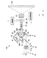
そして、図1に示すように、本実施形態のプロジェクタPJ1においては、液晶ライトバルブ100に、当該液晶ライトバルブ100が備える偏光板101a,101bを移動するための移動機構1(光学素子移動手段)が連結されている。
図4は、移動機構1の概略構成図である。この図に示すように移動機構1は、モータ3と、外部からの信号(M.S)に応じてモータ3を駆動するモータ制御回路2と、液晶ライトバルブ100が備える偏光板101a、101bに接続されかつモータ3によって図中a方向に移動されるスライドギア4とを備えている。そして、モータ制御回路2によってモータ3が駆動されることによって、スライドギア4がa方向に移動され、これによって、スライドギア4に連結された偏光板101a,101bが光の光路Lから外される(相対移動される)。また、モータ制御回路2によってモータ3が逆回転駆動されることによって、偏光板101a,101bが再び液晶パネルを挟み込むように移動される。
As shown in FIG. 1, in the projector PJ1 of the present embodiment, the moving mechanism 1 (optical element moving means) for moving the
FIG. 4 is a schematic configuration diagram of the moving mechanism 1. As shown in this figure, the moving mechanism 1 includes a
投射レンズ110は、液晶ライトバルブ100の表示面上に形成された光学像をスクリーン120上に投射してカラー画像を表示する。
そして、本実施形態のプロジェクタにおいては、投射レンズ110に、当該投射レンズ110の焦点距離を変更するための焦点調整機構5(焦点調整手段)が接続されている。
この焦点調整機構5は、上述の移動機構1が液晶ライトバルブ100の偏光板101a、101bを移動させた場合に生じる焦点距離の変化に応じて、投射レンズ110の焦点距離を変化させるものである。
The
In the projector according to the present embodiment, a focus adjustment mechanism 5 (focus adjustment means) for changing the focal length of the
The
なお、液晶ライトバルブ60B,60G,60R及び液晶ライトバルブ100はいずれも透過光の強度を変調し、その変調度合いに応じた光学像を内包する点では同じであるが、後者の液晶ライトバルブ100は全波長域の光(白色光)を変調するのに対して、前者の液晶ライトバルブ60B,60G,60Rは光分離手段であるダイクロイックミラー30,35で分光された特定波長領域の光(R,G,Bなどの色光)を変調する点で両者は異なっている。したがって、液晶ライトバルブ60B,60G,60Rで行われる光強度変調を色変調、液晶ライトバルブ100で行われる光強度変調を輝度変調と便宜的に呼称して区別する。
The liquid crystal
また、同様の観点から、以下の説明では液晶ライトバルブ60B,60G,60Rを色変調ライトバルブ、液晶ライトバルブ100を輝度変調ライトバルブと呼称して区別する場合がある。
From the same viewpoint, in the following description, the liquid crystal
次に、プロジェクタPJ1の全体的な光伝達の流れを説明する。光源10からの白色光はダイクロイックミラー30,35により赤色(R)、緑色(G)及び青色(B)の3原色光に分光されるとともに、平行化レンズ50B,50G,50Rを含むレンズ及びミラーを介して、液晶ライトバルブ60B,60G,60Rに入射される。液晶ライトバルブ60B,60G,60Rに入射した各々の色光はそれぞれの波長領域に応じた外部データに基づいて色変調され、光学像を内包した変調光として射出される。液晶ライトバルブ60B,60G,60Rからの各変調光は、それぞれクロスダイクロイックプリズム80に入射し、そこで一つの光に合成される。
Next, the overall light transmission flow of the projector PJ1 will be described. The white light from the
その後、クロスダイクロイックプリズム80を射出した光線は、リレーレンズ90を介して液晶ライトバルブ100に入射される。液晶ライトバルブ100に入射した合成光は全波長域に応じた外部データに基づいて輝度変調され、最終的な光学像を内包した変調光として投射レンズ110へ射出される。そして、投射レンズ110において、液晶ライトバルブ100からの最終的な合成光をスクリーン120上に投射し所望の画像を表示する。
Thereafter, the light beam emitted from the cross
このように、プロジェクタPJ1では、第1光変調素子としての液晶ライトバルブ60B,60G,60Rで光学像(画像)を形成した変調光を用いて、最終的な表示画像を第2光変調素子としての液晶ライトバルブ100で形成する形態を採用しており、直列に配置された2つの光変調素子(色変調ライトバルブ及び輝度変調ライトバルブ)を介して、2段階の画像形成過程によって光源10からの光を変調する。なお、画像形成過程については、例えば、「Helge Seetzen, Lorne A. Whitehead “A High Dynamic Range Display Using Low and High Resolution Modulators”, SID Symposium 2003, pp.1450-1453(2003)」に掲載されている。その結果、プロジェクタPJ1は、輝度ダイナミックレンジの拡大と階調数の増大を実現することができる。
Thus, in the projector PJ1, the final display image is used as the second light modulation element by using the modulated light that forms the optical image (image) with the liquid crystal
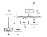
更に、プロジェクタPJ1は、プロジェクタPJ1を制御する表示制御装置200を有している。
図5は、表示制御装置200のハードウェア構成を示すブロック図である。
表示制御装置200は、図5に示すように、制御プログラムに基づいて演算及びシステム全体を制御するCPU170と、所定領域にあらかじめCPU170の制御プログラム等を格納しているROM172と、ROM172等から読み出したデータやCPU170の演算過程で必要な演算結果を格納するためのRAM174と、外部装置に対してデータの入出力を媒介するI/F178とで構成されており、これらは、データを転送するための信号線であるバス179で相互にかつデータ授受可能に接続されている。
Further, the projector PJ1 includes a
FIG. 5 is a block diagram illustrating a hardware configuration of the
As shown in FIG. 5, the
I/F178には、外部装置として、輝度変調ライトバルブ及び色変調ライトバルブを駆動するライトバルブ駆動装置180と、データやテーブル等をファイルとして格納する記憶装置182と、外部のネットワークに接続するための信号線199とが接続されている。なお、本実施形態のプロジェクタPJ1においては、ライトバルブ駆動装置180が、本発明の制御手段としての機能を有している。すなわち、ライトバルブ駆動装置180は、液晶ライトバルブ100の偏光板101a,101bが移動された場合に、液晶ライトバルブ100の液晶パネルが全面白表示となるように駆動する。
The I /
記憶装置182には、輝度変調ライトバルブ及び色変調ライトバルブを駆動するためのHDR表示データおよび制御値登録テーブル等が記憶されている。
The
本実施の形態において、プロジェクタPJ1は、外部からのHDR映像信号及びRGBに基づき表示制御装置200において液晶ライトバルブ60B,60G,60R及び液晶ライトバルブ100の透過率を制御し、スクリーン120上にHDR画像を表示するようになっている。
ここで、HDR画像データは、従来のsRGB等の画像フォーマットでは実現できない高い輝度ダイナミックレンジを実現することができる画像データであり、画素の輝度レベルを示す画素値を画像の全画素について格納している。本実施の形態では、HDR表示データとして、1つの画素についてRGB3原色ごとに輝度レベルを示す画素値を浮動小数点値として格納した形式を用いる。例えば、1つの画素の画素値として(1.2,5.4,2.3)という値が格納されている。
In the present embodiment, the projector PJ1 controls the transmittance of the liquid crystal
Here, the HDR image data is image data capable of realizing a high luminance dynamic range that cannot be realized by a conventional image format such as sRGB, and stores pixel values indicating pixel luminance levels for all pixels of the image. Yes. In the present embodiment, the HDR display data uses a format in which a pixel value indicating a luminance level for each of the three primary colors of RGB is stored as a floating point value for one pixel. For example, the value (1.2, 5.4, 2.3) is stored as the pixel value of one pixel.
また、HDR画像データは、高い輝度ダイナミックレンジのHDR画像を撮影し、撮影したHDR画像に基づいて生成する。
なお、HDR画像データの生成方法の詳細については、例えば公知文献「P.E.Debevec, J.Malik, "Recovering High Dynamic Range Radiance Maps from Photographs", Proceedings of ACM SIGGRAPH97 , p.367-378 , 1997」」に掲載されている。
Also, the HDR image data is generated based on a HDR image having a high luminance dynamic range and a captured HDR image.
For details of the method for generating HDR image data, see, for example, the publicly known document “PEDebevec, J. Malik,“ Recovering High Dynamic Range Radiance Maps from Photographs ”, Proceedings of ACM SIGGRAPH97, p.367-378, 1997”. Has been.
そして、本実施形態のプロジェクタPJ1においては、例えば、外部のネットワークから指示があった場合やHDR画像データが記憶されていないROMがROM172としてセットされた場合には、その外部からの要求に応じてCPU170からその旨を伝える信号が出力される。
In the projector PJ1 of the present embodiment, for example, when an instruction is given from an external network, or when a ROM in which HDR image data is not stored is set as the
そして、その信号が移動機構1のモータ制御回路2に入力されると、モータ制御回路2がモータ3を駆動することによって、スライドギア4が移動され、これによって、液晶ライトバルブ100の偏光板101a,101bが光の光路Lから外される。また、CPU170からの信号は、移動機構1の他に、焦点調整機構5及びライトバルブ駆動装置180にも入力される。そして、焦点調整機構5は、CPU170から信号を入力されることによって、投射レンズ110の焦点距離を調整し、ライトバルブ駆動装置180は、CPU170から信号が入力されることによって、液晶ライトバルブ100の液晶パネルが全面白表示とされるように駆動する。
When the signal is input to the
また、本実施形態のプロジェクタPJ1においては、表示制御装置200は、液晶ライトバルブ100の偏光板101a,101bが光の光路Lから外された場合に、液晶ライトバルブ60R,60G,60Bを駆動するための信号処理を、より良い表示特性が実現できるように変更する。
具体的には、液晶ライトバルブ100の偏光板101a,101bが光の光路Lにある場合のLUT(ルックアップテーブル)と、液晶ライトバルブ100の偏光板101a,101bが光の光路Lから外された場合のLUTとを記憶装置182に予め記憶しておく。そして、CPU170が液晶ライトバルブ100の偏光板101a,101bの状態に応じて記憶装置182に記憶されたLUTを変更することによって、液晶ライトバルブ60R,60G,60Bを駆動するための信号処理を変更することができる。
なお、液晶ライトバルブ100の偏光板101a,101bが光の光路Lにある場合の信号処理データと、液晶ライトバルブ100の偏光板101a,101bが光の光路Lから外された場合のLUTとを1つのLUTとして記憶装置182に記憶しておき、CPU170が液晶ライトバルブ100の偏光板101a,101bの状態に応じてLUTのアドレスの参照先を変更することによって、液晶ライトバルブ60R,60G,60Bを駆動するための信号処理を変更することもできる。
このように、本実施形態のプロジェクタPJ1においては、表示制御装置200が、本発明の信号処理手段としての機能を有している。
In the projector PJ1 of the present embodiment, the
Specifically, the LUT (lookup table) when the
The signal processing data when the
Thus, in the projector PJ1 of this embodiment, the
このような本実施形態のプロジェクタPJ1によれば、光損失の最も大きな光学素子である偏光板101a,101bが光路L上から移動されるため、プロジェクタPJ1の表示特性を明るいものとすることができる。
したがって、本実施形態のプロジェクタPJ1によれば、使用環境に応じて表示特性を変化させることが可能となる。
また、偏光板101a,101bは液晶パネルや照明光の光路程、精密に配置する必要がないため、移動機構1によって、移動させた後、元に戻す場合であっても、比較的に容易に戻すことが可能となる。
また、液晶ライトバルブ100の液晶パネルが全面白表示とされるため、光がほとんど損失せずに液晶パネルを透過するため、より確実にプロジェクタの表示特性を明るいものとすることができる。
また、液晶ライトバルブ100の偏光板101a,101bが光の光路Lから外された場合に、液晶ライトバルブ60R,60G,60Bを駆動するための信号処理が変更可能とされているため、液晶ライトバルブ60R,60G,60Bを好適に駆動することが可能となり、良好な表示特性を得ることが可能となる。
また、焦点調整機構5によって投射レンズ110の焦点距離が、偏光板101a,101bが相対移動されることによって生じる焦点距離の変化に応じて変化されるため、焦点の合った画像をスクリーン120上に表示することができる。
According to the projector PJ1 of this embodiment as described above, since the
Therefore, according to the projector PJ1 of the present embodiment, the display characteristics can be changed according to the use environment.
Further, since it is not necessary to dispose the
Further, since the liquid crystal panel of the liquid crystal
Further, when the
In addition, since the focal length of the
なお、液晶ライトバルブ100の偏光板101a,101bが光の光路Lから外されてる場合においては、液晶パネルは常に全面白表示とされるため、液晶パネルとしてノーマリーホワイト型の液晶パネルを用いることで、プロジェクタPJ1の消費電力を低減させることが可能となる。
Note that when the
また、液晶ライトバルブ100の偏光板101a、101bの両方を光路Lから外すのではなく、どちらか一方を光路Lから外しても良い。
例えば、図6に示すように、液晶ライトバルブ100の偏光板101a(入射側偏光板)のみを移動機構に1と接続することで、偏光板101aのみを光路Lから外しても良い。
ここで、本実施形態のプロジェクタPJ1は、第1光変調素子として液晶ライトバルブ60R,60G,60Bを備えている。このため、液晶ライトバルブ60R,60G,60Bから射出され、第2光変調素子としての液晶ライトバルブ100に入射する光の偏光方向は一方向にほぼ揃えられている。このため、光の偏光方向が偏光板101aの透過軸と平行であれば、偏光板101aのみを光路Lから外した場合であっても、液晶ライトバルブ100を駆動し、液晶ライトバルブ60R,60G,60Bによって変調された光をさらに輝度変調することができる。
ただし、液晶ライトバルブ60R,60G,60Bから射出された光は、途中の光学系(クロスダイクロイックプリズム80やリレーレンズ90)を介して液晶ライトバルブ100に到達するため、その偏光方向が完全に一方向に揃っているわけではない。このため、通常は偏光板101aによって一部が遮光されていた光が、偏光板101aが光路Lから外されることによって、全て液晶ライトバルブ100に入射するため、プロジェクタPJ1の表示特性を明るいものとすることができる。一方で、液晶ライトバルブ100に入射される光の偏光方向にばらつきがあるため、液晶ライトバルブ100における輝度変調の効果が薄れてしまう。
具体的には、偏光板101a及び偏光板101bが共に光路L上にあり液晶ライトバルブ100によって輝度変調が行われる場合には、コントラストが250000:1程度とすることができる。一方で、偏光板101aのみを光路Lから外して液晶ライトバルブ100によって輝度変調が行われる場合には、コントラストが10000:1程度となる。なお、偏光板101a及び偏光板101bを共に光路L上から外して液晶ライトバルブ100によって輝度変調を行わない場合のコントラストは500:1程度である。
また、偏光板101a及び偏光板101bが共に光路L上にあり液晶ライトバルブ100によって輝度変調が行われる場合の輝度を100%とすると、偏光板101aのみを光路Lから外して液晶ライトバルブ100によって輝度変調が行われる場合の輝度は115%程度となり、偏光板101a及び偏光板101bを共に光路L上から外して液晶ライトバルブ100によって輝度変調を行わない場合の輝度は150%程度となる。
Further, instead of removing both the
For example, as shown in FIG. 6, only the
Here, the projector PJ1 of the present embodiment includes liquid
However, since the light emitted from the liquid
Specifically, when both the
If the luminance is 100% when both the
(第2実施形態)
次に、本発明の第2実施形態について説明する。なお、本第2実施形態の説明において、上記第1実施形態と同様の部分については、その説明を省略あるいは簡略化する。
(Second Embodiment)
Next, a second embodiment of the present invention will be described. In the description of the second embodiment, the description of the same parts as in the first embodiment will be omitted or simplified.
図7は、本実施形態のプロジェクタが備える移動機構の概略構成図である。この図に示すように、本実施形態のプロジェクタが備える移動機構においては、スライドギア4が偏光板101a,101bのみでなく、液晶ライトバルブ100そのものに接続されている。
FIG. 7 is a schematic configuration diagram of a moving mechanism provided in the projector according to the present embodiment. As shown in this figure, in the moving mechanism provided in the projector of this embodiment, the slide gear 4 is connected not only to the
このような構成を有する本実施形態のプロジェクタにおいては、外部からの要求があった際に、液晶ライトバルブ100そのものが光路Lから外される。そして、このような構成を有する本実施形態のプロジェクタも、上記第1実施形態のプロジェクタPJ1同様に、使用環境に応じて表示特性を変化させることが可能となる。
In the projector of this embodiment having such a configuration, the liquid crystal
(第3実施形態)
次に、本発明の第3実施形態について説明する。なお、本第3実施形態の説明においても、上記第1実施形態と同様の部分については、その説明を省略あるいは簡略化する。
(Third embodiment)
Next, a third embodiment of the present invention will be described. In the description of the third embodiment, the description of the same parts as those of the first embodiment will be omitted or simplified.
図8は、本実施形態のプロジェクタPJ3の主たる光学構成を示す図である。
この図に示すように、本実施形態のプロジェクタPJ3は、リレーレンズ90と液晶ライトバルブ100との間に波長選択性位相差板300が配置された構成を有している。また、図9の移動機構1の概略構成図に示すように、本実施形態のプロジェクタPJ3においては、移動機構1のスライドギア4が偏光板101a,101bの他、固定板400を介して波長選択性位相差板300と接続された構成を有している。
FIG. 8 is a diagram showing a main optical configuration of the projector PJ3 of the present embodiment.
As shown in this figure, the projector PJ3 of this embodiment has a configuration in which a wavelength-selective
例えば、本実施形態のプロジェクタPJ3のように、RGBの各色の照明光を3つ液晶ライトバルブ60R,60G,60Bによって変調する3板式のプロジェクタである場合には、クロスダイクロイックプリズム80における合成効率の観点から、各液晶ライトバルブにおいて変調された照明光の偏光方向が統一されていない場合がある。このため、各液晶ライトバルブ60R,60G,60Bによって変調された照明光を合成して液晶ライトバルブ100に入射させる場合には、各液晶ライトバルブ60R,60G,60Bによって変調された照明光の偏光方向を統一する必要がある。
そこで、具体的には、液晶ライトバルブ60R,60G,60Bと液晶ライトバルブ100との間に波長選択性を有する位相差板300を配置する。
For example, in the case of a three-plate projector that modulates the illumination light of each color of RGB by three liquid
Therefore, specifically, a
この波長選択性位相差板300は、所定の波長の光(本実施形態においては緑色照明光)にのみ位相差板として作用し、他の波長の光(本実施形態においては赤色照明光及び青色照明光)には位相差板として作用しないものである。このため、波長選択性位相差板300を照明光が通過することによって、所定波長の光の偏光方向のみが変化され、全ての光の偏光方向が統一される。この結果、すべての照明光が偏光方向を統一化され液晶ライトバルブ100に入射可能とされる。
This wavelength-selective
しかしながら、照明光は、このような波長選択性位相差板300を通ることによって多少なりともエネルギーを損失する。具体的には、波長選択性位相差板300を照明光が通ることによって照明光の一部が熱となり、照明光全体としての強度が低下することとなる。
そこで、本実施形態のプロジェクタPJ3のように、液晶ライトバルブ100の偏光板101a,101bを照明光の光路L上から外すような場合、すなわち波長選択性位相差板300が必要とされていない場合には、移動機構1を駆動することによって、液晶ライトバルブ100の偏光板101a,101bとともに波長選択性位相差板300も照明光の光路L上から外すことによって表示画像を明るくすることができる。
However, the illumination light loses some energy by passing through the wavelength selective
Therefore, as in the projector PJ3 of the present embodiment, when the
(第4実施形態)
次に、本発明の第4実施形態について説明する。なお、本第4実施形態の説明において、上記第1実施形態あるいは第2実施形態と同様の部分については、その説明を省略あるいは簡略化する。
(Fourth embodiment)
Next, a fourth embodiment of the present invention will be described. In the description of the fourth embodiment, the description of the same parts as those of the first embodiment or the second embodiment will be omitted or simplified.
図10は、本実施形態のプロジェクタPJ4の主たる光学構成を示す図である。
この図に示すように、本実施形態のプロジェクタPJ4は、液晶ライトバルブ100と一体形成された光路長調整光学素子500を備える構成を有しており、上記第1実施形態のプロジェクタPJ1が備えた焦点調整機構5を備えていない。
FIG. 10 is a diagram showing a main optical configuration of the projector PJ4 of the present embodiment.
As shown in this figure, the projector PJ4 of the present embodiment has a configuration including an optical path length adjusting
光路長調整光学素子500は、照明光の光路長を調整する光学素子であり、液晶ライトバルブ100が光路L上から外された場合に、光路L上に挿入されるものである。具体的には、液晶ライトバルブ100が光路L上から外された場合であっても照明光の光路長が変わらないように、光路長が光路長調整光学素子500によって調整される。
The optical path length adjustment
このような本実施形態のプロジェクタPJ4によれば、液晶ライトバルブ100が光路L上から外された場合であっても光路長調整光学素子500によって照明光の光路長が調整される。このため、焦点調整機構によって投射レンズ110の焦点を調整することなく、焦点の合った画像をスクリーン120上に表示することができる。
According to the projector PJ4 of this embodiment, the optical path length of the illumination light is adjusted by the optical path length adjusting
なお、光路長調整光学素子500としては、照明光に対して透明性を有する光学ガラスやカラーフィルタとして機能する誘電体多層膜ガラス等を用いることができる。そして、誘電体多層膜ガラスを光路長調整光学素子500として用いた場合には、光路長調整光学素子500によって照明光の光路長を調整することができるとともに照明光の色温度補正を行うことができる。
As the optical path length adjusting
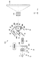
また、本実施形態のプロジェクタPJ4においては、図11の移動機構1の概略構成図に示すように、光学素子である液晶ライトバルブ100と光路長調整光学素子500とが、移動機構1によって液晶ライトバルブ100が移動される方向に直列して接続されることによって一体形成されている。このため、移動機構1によって液晶ライトバルブ100を光路L上から外すと同時に光路長調整光学素子500を光路L上に配置することができる。したがって、別途光路長調整光学素子500を移動する機構を設ける必要がない。なお、本実施形態のプロジェクタPJ4においては、移動機構1が本発明の光路長調整手段の構成要素にも含まれており、移動機構1及び光路長調整光学素子500によって本発明の光路長調整手段が構成されている。
Further, in the projector PJ4 of the present embodiment, as shown in the schematic configuration diagram of the moving mechanism 1 in FIG. 11, the liquid crystal
なお、液晶ライトバルブ100と光路長調整光学素子500とを一体形成する場合には、図12の断面図に示すように、液晶ライトバルブ100が光路長調整光学素子に形成された段差部501に対して貼り付けられることによって一体形成されているという構成を採用することができる。
このような構成を採用することによって、段差部501の高さを調整することによって、液晶ライトバルブ100を光路L上に配置する場合の光路長と、光路長調整光学素子500を光路L上に配置する場合の光路長とを容易に合わせることが可能となる。また、液晶ライトバルブ100以外の光学素子を用いる場合であっても、その光学素子を段差部501に合わせることによって容易に位置決めが可能となるとともに交換作業も容易化される。
In the case where the liquid crystal
By adopting such a configuration, by adjusting the height of the stepped
(第5実施形態)
次に、本発明の第5実施形態について説明する。なお、本第5実施形態の説明においても、上記第1実施形態と同様の部分については、その説明を省略あるいは簡略化する。
(Fifth embodiment)
Next, a fifth embodiment of the present invention will be described. In the description of the fifth embodiment, the description of the same parts as those of the first embodiment will be omitted or simplified.
図13は、本実施形態のプロジェクタPJ5の主たる光学構成を示す図である。
この図に示すように、本実施形態のプロジェクタPJ5は、リレーレンズ90及び液晶ライトバルブ100が、集光レンズ24とダイクロイックミラー30との間に設置されている。なお、本実施形態のプロジェクタPJ5においては、光の進行方向に対して液晶ライトバルブ100、リレーレンズ90の順に配置されている。
FIG. 13 is a diagram showing a main optical configuration of the projector PJ5 of the present embodiment.
As shown in this figure, in the projector PJ5 of this embodiment, the
このような構成を有する本実施形態のプロジェクタPJ5においては、液晶ライトバルブ100によって輝度変調された光がリレーレンズ90を介して各液晶ライトバルブ60R,60G,60Bに入射され、各液晶ライトバルブ60R,60G,60Bにおいて色変調される。すなわち、本実施形態のプロジェクタPJ5においては、本発明の第1光変調素子が液晶ライトバルブ100によって構成され、本発明の第2光変調素子が液晶ライトバルブ60R,60G,60Bによって構成されている。
そして、液晶ライトバルブ100に移動機構1が連結されており、液晶ライトバルブ100そのものを光路L上から外すことが可能とされている。
In the projector PJ5 of this embodiment having such a configuration, light whose luminance is modulated by the liquid crystal
The moving mechanism 1 is connected to the liquid crystal
このような本実施形態のプロジェクタPJ5においても、光損失の大きな光学素子である液晶ライトバルブ100そのものが光路L上から移動可能とされるため、液晶ライトバルブ100を光路L上から外すことによって、プロジェクタPJ5の表示特性を明るいものとすることができる。
Also in the projector PJ5 of this embodiment, since the liquid crystal
また、図13に示すように、液晶ライトバルブ100には位相差板600(1/2波長板)が一体形成されている。位相差板600は、入射する光の偏光方向を変化させるものであり、液晶ライトバルブ100が光路L上から外された場合に、光路L上に挿入される。
液晶ライトバルブ100に入射される光は、偏光変換素子23によってその偏光方向が揃えられており、液晶ライトバルブ100から射出されることによって偏光方向が変化される。ここで、液晶ライトバルブ100が光路L上から外された場合には、光の偏光方向が変化されないため、後段の液晶ライトバルブ60R,60G,60Bに光が入射することができない。このため、液晶ライトバルブ100が光路L上から外された場合に、位相差板600を光路L上に挿入することよって、液晶ライトバルブ60R,60G,60Bに入射可能な偏光方向の光に変換する。
As shown in FIG. 13, the liquid crystal
The polarization direction of the light incident on the liquid crystal
なお、本実施形態においては、移動機構1によって液晶ライトバルブ100そのものを移動させた。しかしながら、本発明はこれに限定されるものではなく、移動機構1によって液晶ライトバルブ100の偏光板101a及び101bのみを移動させても良い。
In the present embodiment, the liquid crystal
(第6実施形態)
次に、本発明の第6実施形態について説明する。なお、本第6実施形態の説明においても、上記第1実施形態と同様の部分については、その説明を省略あるいは簡略化する。
(Sixth embodiment)
Next, a sixth embodiment of the present invention will be described. In the description of the sixth embodiment, the description of the same parts as those in the first embodiment will be omitted or simplified.
上記第1〜第5実施形態のプロジェクタが光学素子を移動させることによって光学素子と光路Lとを相対移動させる構成であるのに対して、本実施形態のプロジェクタは、光路Lを移動させることによって光学素子(液晶ライトバルブ100)と光路Lとを相対移動させる構成を有している。 While the projectors of the first to fifth embodiments are configured to move the optical element and the optical path L relative to each other by moving the optical element, the projector of the present embodiment moves the optical path L. The optical element (liquid crystal light valve 100) and the optical path L are relatively moved.
図14は、本実施形態のプロジェクタPJ6の主たる光学構成を示す図である。
この図に示すように、本実施形態のプロジェクタPJ6においては、集光レンズ24とダイクロイックミラー30との間の光路Lが光路L1と光路L2とに分離されている。なお、本実施形態のプロジェクタPJ6においては、偏光変換素子23から射出される光がs偏光であり、液晶ライトバルブ60R,60G,60Bに入射可能な光がp偏光であるとする。
FIG. 14 is a diagram showing a main optical configuration of the projector PJ6 of the present embodiment.
As shown in this figure, in the projector PJ6 of this embodiment, the optical path L between the
そして、本実施形態のプロジェクタPJ6は、光路Lに対して移動可能であるとともに光路L上においては光を反射することによって光路L1に導光する可動式反射ミラー701(光学素子移動手段)を備えている。すなわち、可動式反射ミラー701が光路L上に設置されている場合には、光が光路L1に導光され、可動式反射ミラー701が光路L上に設置されていない場合には、光が光路L2に導光される。
光路L1上には、複数のリレーレンズ702と、反射ミラー703が設置されており、光路L1に導光された光は、これらの光学系によって偏光ビームスプリッタ704に導光される。
一方、光路L2上には、s偏光を液晶ライトバルブ100側に反射する偏光ビームスプリッタ705、及びリレーレンズ90が設置されており、光路L2に導光された光は、これらの光学系によって偏光ビームスプリッタ704に導光される。なお、本実施形態においては、液晶ライトバルブ100が反射型の液晶ライトバルブとして構成されている。
偏光ビームスプリッタ704は、s偏光を反射することによってダイクロイックミラー30側に導光し、p偏光を透過することによってダイクロイックミラー30側に導光するものである。
また、偏光ビームスプリッタ704とダイクロイックミラー30との間には、光が光路L1を通過してきた場合(可動式反射ミラー701が光路L上にある場合)に光路L上に設置される可動式位相差板706が設置されている。
The projector PJ6 of the present embodiment includes a movable reflective mirror 701 (optical element moving unit) that is movable with respect to the optical path L and that guides the light to the optical path L1 by reflecting light on the optical path L. ing. That is, when the
A plurality of
On the other hand, a
The
Also, a movable position installed on the optical path L between the
このような構成を有する本実施形態のプロジェクタPJ6においては、可動式反射ミラー701が光路L上に移動された場合には、光が光路L1に導光される。そして、光路L1に導光された光(s偏光)が複数のリレーレンズ702と、反射ミラー703によって偏光ビームスプリッタ704に導光される。ここで、偏光ビームスプリッタ704は、s偏光を反射することによってダイクロイックミラー30側に導光するものであるため、光路L1を介して偏光ビームスプリッタ704に導光された光は、偏光ビームスプリッタ704に反射されることによってダイクロイックミラー30側に導光される。また、可動式反射ミラー701が光路L上にある場合には、光路L上に可動式位相差板706が設置されるため、偏光ビームスプリッタ704から射出された光は、可動式位相差板706によって、液晶ライトバルブ60R,60G,60Bに入射可能なp偏光に変化されて射出される。
一方、可動式反射ミラー701が光路L上から外されている場合には、光が光路L2に導光される。そして、光路L2に導光された光は、偏光ビームスプリッタ705によって液晶ライトバルブ100に導光され、輝度変調された後、リレーレンズ90を介して偏光ビームスプリッタ704に導光される。このように光路L2を通って偏光ビームスプリッタ704に導光される光は、液晶ライトバルブ100によってp偏光に変化されているため、偏光ビームスプリッタ704を透過することによってダイクロイックミラー30側に導光される。
In the projector PJ6 of this embodiment having such a configuration, when the movable
On the other hand, when the
このような本実施形態のプロジェクタPJ6においては、光を光路L1に導光するすなわち光路を移動させることによって、液晶ライトバルブ100を光路上から外すことができる。したがって、光を光路L1に導光することによって、上記第1実施形態のプロジェクタと同様に、表示特性を明るいものとすることができる。
In the projector PJ6 of this embodiment, the liquid crystal
また、本実施形態のプロジェクタPJ6においては、液晶ライトバルブ100によって変調された光が各液晶ライトバルブ60R,60G,60Bによって変調されているため、本発明の第1光変調素子が液晶ライトバルブ100によって構成され、本発明の第2光変調素子が液晶ライトバルブ60R,60G,60Bによって構成されている。
In the projector PJ6 of the present embodiment, the light modulated by the liquid crystal
(第7実施形態)
次に、本発明の第7実施形態について説明する。なお、本第7実施形態は、上記第6実施形態の変形例であるため、上記第6実施形態と同様の部分については、その説明を省略あるいは簡略化する。
(Seventh embodiment)
Next, a seventh embodiment of the present invention will be described. Since the seventh embodiment is a modification of the sixth embodiment, the description of the same parts as the sixth embodiment will be omitted or simplified.
図15は、本実施形態のプロジェクタPJ7の主たる光学構成を示す図である。
この図に示すように、本実施形態のプロジェクタPJ7は、上記第6実施形態のプロジェクタPJ6が備えた可動式反射ミラー701の替わりに、光路Lに対して移動可能な可動式位相差板801と、偏光ビームスプリッタ802とを備えている。すなわち、本実施形態のプロジェクタPJ7においては、本発明の光学素子移動手段が可動式位相差板801及び偏光ビームスプリッタ802によって構成されている。
偏光ビームスプリッタ802は、p偏光を反射することによって光路L1に導光し、s偏光を透過することによって光路L2に導光する。
このため、本実施形態のプロジェクタPJ7においては、可動式位相差板801を光路L上に設置することによって、集光レンズ24から射出されたs偏光がp偏光に変化され、偏光ビームスプリッタ802において反射されることで光路L1に導光される。
一方、可動式位相差板801を光路L上から外すことによって、集光レンズ24から射出されたs偏光が偏光ビームスプリッタ802を透過して光路L2に導光される。
すなわち、本実施形態のプロジェクタPJ7によれば、可動式位相差板801を移動することによって、光路を移動することができる。
FIG. 15 is a diagram showing a main optical configuration of the projector PJ7 of the present embodiment.
As shown in this figure, the projector PJ7 of the present embodiment includes a movable
The
For this reason, in the projector PJ7 of the present embodiment, the s-polarized light emitted from the
On the other hand, by removing the
That is, according to the projector PJ7 of this embodiment, the optical path can be moved by moving the
なお、本実施形態においては、光路L1に導光されるのはp偏光であるため、これをs偏光に戻す必要がある。このため、光路L1上に位相差板803が設置されている。
In the present embodiment, since the p-polarized light is guided to the optical path L1, it is necessary to return it to the s-polarized light. For this reason, the
以上、添付図面を参照しながら本発明に係るプロジェクタの好適な実施形態について説明したが、本発明は上記実施形態に限定されないことは言うまでもない。上述した実施形態において示した各構成部材の諸形状や組み合わせ等は一例であって、本発明の主旨から逸脱しない範囲において設計要求等に基づき種々変更可能である。 The preferred embodiments of the projector according to the present invention have been described above with reference to the accompanying drawings. Needless to say, the present invention is not limited to the above embodiments. Various shapes, combinations, and the like of the constituent members shown in the above-described embodiments are examples, and various modifications can be made based on design requirements and the like without departing from the gist of the present invention.
例えば、上記第1実施形態においては、移動機構によって偏光板101a,101bあるいは液晶ライトバルブ100のみを移動した。しかしながら、本発明は、これに限定されるものではなく、偏光板101a,101bあるいは液晶ライトバルブ100と同時にリレーレンズ90も移動機構によって移動させても良い。
For example, in the first embodiment, only the
また、偏光板101a,101bあるいは液晶ライトバルブ100の移動方向及び移動方法も任意である。
Further, the moving direction and moving method of the
また、上記実施形態においては、光変調素子として、透過型の液晶ライトバルブを用いた。しかしながら、本発明は、これに限定されるものではなく、光変調素子として、反射型の液晶ライトバルブや微小ミラーアレイデバイスを用いることも可能である。 In the above embodiment, a transmissive liquid crystal light valve is used as the light modulation element. However, the present invention is not limited to this, and a reflective liquid crystal light valve or a micromirror array device can also be used as the light modulation element.
また、例えば、上記実施形態のスクリーンを筐体の一部に露出して設置し、上記実施形態のスクリーン以外の構成を筐体の内部に収納し、筐体の内部からスクリーンに対して背面投写することによって画像を表示する、いわゆるリアプロジェクタに本発明を適用することも可能である。 In addition, for example, the screen of the above-described embodiment is installed in a part of the housing, the configuration other than the screen of the above-described embodiment is housed in the housing, and rear projection is performed on the screen from the inside of the housing Thus, the present invention can be applied to a so-called rear projector that displays an image.
PJ1,PJ3〜PJ7……プロジェクタ、1……移動機構(光学素子移動手段)、5……焦点調整機構(焦点調整手段)60B,60G,60R……液晶ライトバルブ(第1光変調素子)、100……液晶ライトバルブ(第2光変調素子)、101a,101b……偏光板、110……投射レンズ(投射手段)、180……ライトバルブ駆動装置(制御手段)、300……波長選択性位相差板、500……光路長調整光学素子、701……可動式反射ミラー(光学素子移動手段)、801……可動式位相差板、802……偏光ビームスプリッタ PJ1, PJ3 to PJ7 ... projector, 1 ... moving mechanism (optical element moving means), 5 ... focus adjusting mechanism (focus adjusting means) 60B, 60G, 60R ... liquid crystal light valve (first light modulating element), 100 ... Liquid crystal light valve (second light modulation element), 101a, 101b ... Polarizing plate, 110 ... Projection lens (projection means), 180 ... Light valve drive device (control means), 300 ... Wavelength selectivity Phase difference plate, 500... Optical path length adjusting optical element, 701. Movable reflection mirror (optical element moving means), 801. Movable phase difference plate, 802.
Claims (21)
前記照明光の少なくとも一部を遮る光学素子を前記照明光の光路に対して相対移動させることによって前記光路上から外す光学素子移動手段を備え、
前記光学素子は、前記第2光変調素子である
ことを特徴とするプロジェクタ。 A first light modulation element that modulates illumination light, a second light modulation element that further modulates the illumination light modulated by the first light modulation element, and a projection that projects the modulated illumination light toward a screen A projector comprising means,
Optical element moving means for removing the optical element that blocks at least part of the illumination light from the optical path by moving the optical element relative to the optical path of the illumination light ;
The projector , wherein the optical element is the second light modulation element .
前記照明光の少なくとも一部を遮る光学素子を前記照明光の光路に対して相対移動させることによって前記光路上から外す光学素子移動手段を備え、
前記第2光変調素子が透過型の液晶ライトバルブであり、前記光学素子は、前記第2光変調素子が備える偏光板である
ことを特徴とするプロジェクタ。 A first light modulation element that modulates illumination light, a second light modulation element that further modulates the illumination light modulated by the first light modulation element, and a projection that projects the modulated illumination light toward a screen A projector comprising means,
Optical element moving means for removing the optical element that blocks at least part of the illumination light from the optical path by moving the optical element relative to the optical path of the illumination light ;
The projector, wherein the second light modulation element is a transmissive liquid crystal light valve, and the optical element is a polarizing plate included in the second light modulation element .
前記照明光の少なくとも一部を遮る光学素子を前記照明光の光路に対して相対移動させることによって前記光路上から外す光学素子移動手段を備え、
前記光学素子は、前記第1光変調素子によって変調された前記照明光の偏光方向を前記第2光変調素子の入射偏光方向に揃える波長選択位相差板である
ことを特徴とする請求項1記載のプロジェクタ。 A first light modulation element that modulates illumination light, a second light modulation element that further modulates the illumination light modulated by the first light modulation element, and a projection that projects the modulated illumination light toward a screen A projector comprising means,
Optical element moving means for removing the optical element that blocks at least part of the illumination light from the optical path by moving the optical element relative to the optical path of the illumination light ;
The optical element is a wavelength selection phase difference plate that aligns the polarization direction of the illumination light modulated by the first light modulation element with the incident polarization direction of the second light modulation element. Projector.
前記照明光の少なくとも一部を遮る光学素子を前記照明光の光路に対して相対移動させることによって前記光路上から外す光学素子移動手段と、
前記光学素子が前記光路上から外されている場合に、前記投射手段の焦点距離を合わせる焦点調整手段と
を備えることを特徴とするプロジェクタ。 A first light modulation element that modulates illumination light, a second light modulation element that further modulates the illumination light modulated by the first light modulation element, and a projection that projects the modulated illumination light toward a screen A projector comprising means,
An optical element moving means for removing the optical element that blocks at least a part of the illumination light from the optical path by moving the optical element relative to the optical path of the illumination light ;
A projector comprising: a focus adjustment unit that adjusts a focal length of the projection unit when the optical element is removed from the optical path .
前記照明光の少なくとも一部を遮る光学素子を前記照明光の光路に対して相対移動させることによって前記光路上から外す光学素子移動手段と、
前記光学素子が前記光路上から外されている場合に、前記照明光の光路長を調整する光路長調整手段と
を備えることを特徴とするプロジェクタ。 A first light modulation element that modulates illumination light, a second light modulation element that further modulates the illumination light modulated by the first light modulation element, and a projection that projects the modulated illumination light toward a screen A projector comprising means,
An optical element moving means for removing the optical element that blocks at least a part of the illumination light from the optical path by moving the optical element relative to the optical path of the illumination light ;
A projector comprising: an optical path length adjusting unit configured to adjust an optical path length of the illumination light when the optical element is removed from the optical path .
前記照明光の少なくとも一部を遮る光学素子を前記照明光の光路に対して相対移動させることによって前記光路上から外す光学素子移動手段を備え、
前記光学素子は、前記第1光変調素子である
ことを特徴とするプロジェクタ。 A first light modulation element that modulates illumination light, a second light modulation element that further modulates the illumination light modulated by the first light modulation element, and a projection that projects the modulated illumination light toward a screen A projector comprising means,
Optical element moving means for removing the optical element that blocks at least part of the illumination light from the optical path by moving the optical element relative to the optical path of the illumination light ;
The projector , wherein the optical element is the first light modulation element .
前記照明光の少なくとも一部を遮る光学素子を前記照明光の光路に対して相対移動させることによって前記光路上から外す光学素子移動手段を備え、
前記第1光変調素子が透過型の液晶ライトバルブであり、前記光学素子は、前記第1光変調素子が備える偏光板である
ことを特徴とするプロジェクタ。 A first light modulation element that modulates illumination light, a second light modulation element that further modulates the illumination light modulated by the first light modulation element, and a projection that projects the modulated illumination light toward a screen A projector comprising means,
Optical element moving means for removing the optical element that blocks at least part of the illumination light from the optical path by moving the optical element relative to the optical path of the illumination light ;
The projector, wherein the first light modulation element is a transmissive liquid crystal light valve, and the optical element is a polarizing plate included in the first light modulation element .
前記照明光の少なくとも一部を遮る光学素子を前記照明光の光路に対して相対移動させることによって前記光路上から外す光学素子移動手段を備え、
前記第1光変調素子及び前記第2光変調素子が液晶ライトバルブであり、前記光学素子は、前記第2光変調素子が備える入射側偏光板である
ことを特徴とするプロジェクタ。 A first light modulation element that modulates illumination light, a second light modulation element that further modulates the illumination light modulated by the first light modulation element, and a projection that projects the modulated illumination light toward a screen A projector comprising means,
Optical element moving means for removing the optical element that blocks at least part of the illumination light from the optical path by moving the optical element relative to the optical path of the illumination light ;
The projector according to claim 1, wherein the first light modulation element and the second light modulation element are liquid crystal light valves, and the optical element is an incident side polarizing plate included in the second light modulation element .
Priority Applications (2)
| Application Number | Priority Date | Filing Date | Title |
|---|---|---|---|
| JP2006029343A JP4893004B2 (en) | 2005-03-24 | 2006-02-07 | projector |
| US11/387,859 US7712902B2 (en) | 2005-03-24 | 2006-03-24 | Projector |
Applications Claiming Priority (5)
| Application Number | Priority Date | Filing Date | Title |
|---|---|---|---|
| JP2005085838 | 2005-03-24 | ||
| JP2005085838 | 2005-03-24 | ||
| JP2005316276 | 2005-10-31 | ||
| JP2005316276 | 2005-10-31 | ||
| JP2006029343A JP4893004B2 (en) | 2005-03-24 | 2006-02-07 | projector |
Publications (3)
| Publication Number | Publication Date |
|---|---|
| JP2007148319A JP2007148319A (en) | 2007-06-14 |
| JP2007148319A5 JP2007148319A5 (en) | 2008-10-30 |
| JP4893004B2 true JP4893004B2 (en) | 2012-03-07 |
Family
ID=37034790
Family Applications (1)
| Application Number | Title | Priority Date | Filing Date |
|---|---|---|---|
| JP2006029343A Expired - Fee Related JP4893004B2 (en) | 2005-03-24 | 2006-02-07 | projector |
Country Status (2)
| Country | Link |
|---|---|
| US (1) | US7712902B2 (en) |
| JP (1) | JP4893004B2 (en) |
Families Citing this family (16)
| Publication number | Priority date | Publication date | Assignee | Title |
|---|---|---|---|---|
| JP2009156898A (en) * | 2007-12-25 | 2009-07-16 | Seiko Epson Corp | Display device |
| JP5360683B2 (en) * | 2009-04-01 | 2013-12-04 | セイコーエプソン株式会社 | projector |
| JP2012163944A (en) * | 2011-01-21 | 2012-08-30 | Panasonic Corp | Projection type display device |
| JP2013054142A (en) * | 2011-09-02 | 2013-03-21 | Sony Corp | Polarization optical device, optical device, and projecting device |
| JP6047968B2 (en) * | 2012-07-17 | 2016-12-21 | セイコーエプソン株式会社 | Projector and light emission control method in projector |
| JP6019859B2 (en) | 2012-07-17 | 2016-11-02 | セイコーエプソン株式会社 | Projector and light emission control method in projector |
| JP6237020B2 (en) * | 2013-09-13 | 2017-11-29 | セイコーエプソン株式会社 | Image display device and method for controlling image display device |
| JP6330286B2 (en) | 2013-10-22 | 2018-05-30 | セイコーエプソン株式会社 | projector |
| JP6471424B2 (en) | 2013-11-13 | 2019-02-20 | セイコーエプソン株式会社 | projector |
| JP6331382B2 (en) * | 2013-12-26 | 2018-05-30 | セイコーエプソン株式会社 | Image display device and method for controlling image display device |
| JP6331383B2 (en) * | 2013-12-26 | 2018-05-30 | セイコーエプソン株式会社 | Image display device and method for controlling image display device |
| US20230027499A1 (en) * | 2014-05-15 | 2023-01-26 | Mtt Innovation Incorporated | Optimizing drive schemes for multiple projector systems |
| EP3143763B8 (en) * | 2014-05-15 | 2023-12-27 | MTT Innovation Incorporated | Light projector and method for displaying an image |
| US10036938B2 (en) | 2014-06-27 | 2018-07-31 | Dolby Laboratories Licensing Corporation | Light recycling for projectors with high dynamic range |
| CN107272307B (en) * | 2016-04-08 | 2020-11-17 | 信泰光学(深圳)有限公司 | Projection device |
| CN110830785B (en) * | 2016-09-30 | 2021-09-03 | 杜比实验室特许公司 | Beam combining for highlight projection |
Family Cites Families (20)
| Publication number | Priority date | Publication date | Assignee | Title |
|---|---|---|---|---|
| JPH02144516A (en) * | 1988-11-25 | 1990-06-04 | Toshiba Corp | Liquid crystal projector |
| JPH0481714A (en) * | 1990-07-25 | 1992-03-16 | Canon Inc | Liquid crystal projection device |
| JPH05224155A (en) * | 1992-02-10 | 1993-09-03 | Fujitsu Ltd | Projection type liquid crystal display device |
| JP3316240B2 (en) * | 1992-11-30 | 2002-08-19 | 三洋電機株式会社 | Color lcd projector |
| JPH09189893A (en) * | 1996-01-09 | 1997-07-22 | Nec Corp | Liquid crystal projector |
| GB2317290B (en) * | 1996-09-11 | 2000-12-06 | Seos Displays Ltd | Image display apparatus |
| US5722752A (en) * | 1997-01-10 | 1998-03-03 | In Focus Systems, Inc. | Multimedia projection system with image quality correction |
| JP3495645B2 (en) | 1999-06-04 | 2004-02-09 | 日本アビオニクス株式会社 | Lamp adjustment device for liquid crystal projector and adjustment method using the same |
| JP2001100689A (en) | 1999-09-30 | 2001-04-13 | Canon Inc | Display device |
| DE60237440D1 (en) | 2001-02-27 | 2010-10-07 | Dolby Lab Licensing Corp | IMAGE DISPLAY DEVICES WITH LARGE DYNAMIC RANGE |
| AU2003295989A1 (en) * | 2002-12-04 | 2004-06-23 | Thomson Licensing S.A. | Two-stage projector architecture |
| MXPA05005805A (en) * | 2002-12-04 | 2005-08-16 | Thomson Licensing Sa | Two-stage projection architecture. |
| JP4461703B2 (en) * | 2003-04-23 | 2010-05-12 | セイコーエプソン株式会社 | projector |
| JP4219745B2 (en) * | 2003-06-19 | 2009-02-04 | 株式会社ディーアンドエムホールディングス | Projector device |
| US7070284B2 (en) * | 2003-06-19 | 2006-07-04 | Marantz Japan, Inc. | Projector apparatus |
| TWM245454U (en) * | 2003-08-05 | 2004-10-01 | Benq Corp | Light shielding device of projector and projector having the device |
| JP4244904B2 (en) * | 2003-12-24 | 2009-03-25 | セイコーエプソン株式会社 | Optical system light propagation structure and optical display device, optical system light propagation method, and optical display device display method |
| JP4158757B2 (en) | 2003-12-24 | 2008-10-01 | セイコーエプソン株式会社 | Optical display device and projection display device |
| JP4029852B2 (en) * | 2004-03-23 | 2008-01-09 | セイコーエプソン株式会社 | Optical display device, optical display device control program, and optical display device control method |
| JP4158776B2 (en) * | 2005-03-09 | 2008-10-01 | セイコーエプソン株式会社 | Image display device and projector |
-
2006
- 2006-02-07 JP JP2006029343A patent/JP4893004B2/en not_active Expired - Fee Related
- 2006-03-24 US US11/387,859 patent/US7712902B2/en not_active Expired - Fee Related
Also Published As
| Publication number | Publication date |
|---|---|
| US7712902B2 (en) | 2010-05-11 |
| JP2007148319A (en) | 2007-06-14 |
| US20060215130A1 (en) | 2006-09-28 |
Similar Documents
| Publication | Publication Date | Title |
|---|---|---|
| JP4893004B2 (en) | projector | |
| JP4301304B2 (en) | Image display device | |
| JP4158776B2 (en) | Image display device and projector | |
| US7841725B2 (en) | Image display device and projector | |
| US7443565B2 (en) | Image display apparatus, projector, and polarization compensation system | |
| JP2005250235A (en) | Optical modulating device, optical display device, optical modulation control program, optical display device control program, optical modulation control method, and optical display device control method | |
| CN100374905C (en) | Projector | |
| JP2007206343A (en) | Optical display device and method | |
| JP2009156898A (en) | Display device | |
| JP4059233B2 (en) | Image display device and projector | |
| JP4285425B2 (en) | Image display device and projector | |
| JP2006243477A (en) | Image display device and projector | |
| JP2007264339A (en) | Modulating device and projector | |
| JP4241872B2 (en) | Image display device, projector, polarization compensation optical system | |
| CN113168080B (en) | Image display device | |
| JP2006308641A (en) | Image display device and projector | |
| JP2009156900A (en) | Image quality conversion unit | |
| JP4539099B2 (en) | Projection type display device, control method for projection type display device, and image output device | |
| JP2006106583A (en) | Image display device | |
| JP2009204693A (en) | Projector and manufacturing method thereof | |
| JP2007264340A (en) | Image display device and projector | |
| JP2006084760A (en) | Multi-projection display | |
| JP4788757B2 (en) | Optical display device | |
| JP4715120B2 (en) | Image display device driving method, image display device, and projector | |
| JP2007225970A (en) | Image display device and projector |
Legal Events
| Date | Code | Title | Description |
|---|---|---|---|
| A521 | Written amendment |
Free format text: JAPANESE INTERMEDIATE CODE: A523 Effective date: 20080908 |
|
| A621 | Written request for application examination |
Free format text: JAPANESE INTERMEDIATE CODE: A621 Effective date: 20080908 |
|
| A521 | Written amendment |
Free format text: JAPANESE INTERMEDIATE CODE: A821 Effective date: 20080909 |
|
| A131 | Notification of reasons for refusal |
Free format text: JAPANESE INTERMEDIATE CODE: A131 Effective date: 20110712 |
|
| A521 | Written amendment |
Free format text: JAPANESE INTERMEDIATE CODE: A523 Effective date: 20110908 |
|
| A521 | Written amendment |
Free format text: JAPANESE INTERMEDIATE CODE: A821 Effective date: 20110909 |
|
| TRDD | Decision of grant or rejection written | ||
| A01 | Written decision to grant a patent or to grant a registration (utility model) |
Free format text: JAPANESE INTERMEDIATE CODE: A01 Effective date: 20111122 |
|
| A01 | Written decision to grant a patent or to grant a registration (utility model) |
Free format text: JAPANESE INTERMEDIATE CODE: A01 |
|
| A61 | First payment of annual fees (during grant procedure) |
Free format text: JAPANESE INTERMEDIATE CODE: A61 Effective date: 20111205 |
|
| R150 | Certificate of patent or registration of utility model |
Ref document number: 4893004 Country of ref document: JP Free format text: JAPANESE INTERMEDIATE CODE: R150 Free format text: JAPANESE INTERMEDIATE CODE: R150 |
|
| FPAY | Renewal fee payment (event date is renewal date of database) |
Free format text: PAYMENT UNTIL: 20150106 Year of fee payment: 3 |
|
| S531 | Written request for registration of change of domicile |
Free format text: JAPANESE INTERMEDIATE CODE: R313531 |
|
| R350 | Written notification of registration of transfer |
Free format text: JAPANESE INTERMEDIATE CODE: R350 |
|
| LAPS | Cancellation because of no payment of annual fees |