JP2005250235A - Optical modulating device, optical display device, optical modulation control program, optical display device control program, optical modulation control method, and optical display device control method - Google Patents
Optical modulating device, optical display device, optical modulation control program, optical display device control program, optical modulation control method, and optical display device control method Download PDFInfo
- Publication number
- JP2005250235A JP2005250235A JP2004062294A JP2004062294A JP2005250235A JP 2005250235 A JP2005250235 A JP 2005250235A JP 2004062294 A JP2004062294 A JP 2004062294A JP 2004062294 A JP2004062294 A JP 2004062294A JP 2005250235 A JP2005250235 A JP 2005250235A
- Authority
- JP
- Japan
- Prior art keywords
- light
- modulation element
- light modulation
- pixels
- pixel
- Prior art date
- Legal status (The legal status is an assumption and is not a legal conclusion. Google has not performed a legal analysis and makes no representation as to the accuracy of the status listed.)
- Pending
Links
Images


Classifications
-
- H—ELECTRICITY
- H04—ELECTRIC COMMUNICATION TECHNIQUE
- H04N—PICTORIAL COMMUNICATION, e.g. TELEVISION
- H04N9/00—Details of colour television systems
- H04N9/12—Picture reproducers
- H04N9/31—Projection devices for colour picture display, e.g. using electronic spatial light modulators [ESLM]
- H04N9/3102—Projection devices for colour picture display, e.g. using electronic spatial light modulators [ESLM] using two-dimensional electronic spatial light modulators
- H04N9/3105—Projection devices for colour picture display, e.g. using electronic spatial light modulators [ESLM] using two-dimensional electronic spatial light modulators for displaying all colours simultaneously, e.g. by using two or more electronic spatial light modulators
-
- G—PHYSICS
- G09—EDUCATION; CRYPTOGRAPHY; DISPLAY; ADVERTISING; SEALS
- G09G—ARRANGEMENTS OR CIRCUITS FOR CONTROL OF INDICATING DEVICES USING STATIC MEANS TO PRESENT VARIABLE INFORMATION
- G09G3/00—Control arrangements or circuits, of interest only in connection with visual indicators other than cathode-ray tubes
- G09G3/001—Control arrangements or circuits, of interest only in connection with visual indicators other than cathode-ray tubes using specific devices not provided for in groups G09G3/02 - G09G3/36, e.g. using an intermediate record carrier such as a film slide; Projection systems; Display of non-alphanumerical information, solely or in combination with alphanumerical information, e.g. digital display on projected diapositive as background
- G09G3/002—Control arrangements or circuits, of interest only in connection with visual indicators other than cathode-ray tubes using specific devices not provided for in groups G09G3/02 - G09G3/36, e.g. using an intermediate record carrier such as a film slide; Projection systems; Display of non-alphanumerical information, solely or in combination with alphanumerical information, e.g. digital display on projected diapositive as background to project the image of a two-dimensional display, such as an array of light emitting or modulating elements or a CRT
-
- H—ELECTRICITY
- H04—ELECTRIC COMMUNICATION TECHNIQUE
- H04N—PICTORIAL COMMUNICATION, e.g. TELEVISION
- H04N9/00—Details of colour television systems
- H04N9/12—Picture reproducers
- H04N9/31—Projection devices for colour picture display, e.g. using electronic spatial light modulators [ESLM]
- H04N9/3102—Projection devices for colour picture display, e.g. using electronic spatial light modulators [ESLM] using two-dimensional electronic spatial light modulators
- H04N9/312—Driving therefor
- H04N9/3126—Driving therefor for spatial light modulators in series
-
- G—PHYSICS
- G09—EDUCATION; CRYPTOGRAPHY; DISPLAY; ADVERTISING; SEALS
- G09G—ARRANGEMENTS OR CIRCUITS FOR CONTROL OF INDICATING DEVICES USING STATIC MEANS TO PRESENT VARIABLE INFORMATION
- G09G2310/00—Command of the display device
- G09G2310/02—Addressing, scanning or driving the display screen or processing steps related thereto
- G09G2310/0235—Field-sequential colour display
-
- G—PHYSICS
- G09—EDUCATION; CRYPTOGRAPHY; DISPLAY; ADVERTISING; SEALS
- G09G—ARRANGEMENTS OR CIRCUITS FOR CONTROL OF INDICATING DEVICES USING STATIC MEANS TO PRESENT VARIABLE INFORMATION
- G09G2320/00—Control of display operating conditions
- G09G2320/06—Adjustment of display parameters
- G09G2320/066—Adjustment of display parameters for control of contrast
-
- G—PHYSICS
- G09—EDUCATION; CRYPTOGRAPHY; DISPLAY; ADVERTISING; SEALS
- G09G—ARRANGEMENTS OR CIRCUITS FOR CONTROL OF INDICATING DEVICES USING STATIC MEANS TO PRESENT VARIABLE INFORMATION
- G09G2360/00—Aspects of the architecture of display systems
- G09G2360/16—Calculation or use of calculated indices related to luminance levels in display data
-
- G—PHYSICS
- G09—EDUCATION; CRYPTOGRAPHY; DISPLAY; ADVERTISING; SEALS
- G09G—ARRANGEMENTS OR CIRCUITS FOR CONTROL OF INDICATING DEVICES USING STATIC MEANS TO PRESENT VARIABLE INFORMATION
- G09G3/00—Control arrangements or circuits, of interest only in connection with visual indicators other than cathode-ray tubes
- G09G3/20—Control arrangements or circuits, of interest only in connection with visual indicators other than cathode-ray tubes for presentation of an assembly of a number of characters, e.g. a page, by composing the assembly by combination of individual elements arranged in a matrix no fixed position being assigned to or needed to be assigned to the individual characters or partial characters
- G09G3/2007—Display of intermediate tones
- G09G3/2011—Display of intermediate tones by amplitude modulation
-
- G—PHYSICS
- G09—EDUCATION; CRYPTOGRAPHY; DISPLAY; ADVERTISING; SEALS
- G09G—ARRANGEMENTS OR CIRCUITS FOR CONTROL OF INDICATING DEVICES USING STATIC MEANS TO PRESENT VARIABLE INFORMATION
- G09G3/00—Control arrangements or circuits, of interest only in connection with visual indicators other than cathode-ray tubes
- G09G3/20—Control arrangements or circuits, of interest only in connection with visual indicators other than cathode-ray tubes for presentation of an assembly of a number of characters, e.g. a page, by composing the assembly by combination of individual elements arranged in a matrix no fixed position being assigned to or needed to be assigned to the individual characters or partial characters
- G09G3/2007—Display of intermediate tones
- G09G3/2014—Display of intermediate tones by modulation of the duration of a single pulse during which the logic level remains constant
-
- G—PHYSICS
- G09—EDUCATION; CRYPTOGRAPHY; DISPLAY; ADVERTISING; SEALS
- G09G—ARRANGEMENTS OR CIRCUITS FOR CONTROL OF INDICATING DEVICES USING STATIC MEANS TO PRESENT VARIABLE INFORMATION
- G09G3/00—Control arrangements or circuits, of interest only in connection with visual indicators other than cathode-ray tubes
- G09G3/20—Control arrangements or circuits, of interest only in connection with visual indicators other than cathode-ray tubes for presentation of an assembly of a number of characters, e.g. a page, by composing the assembly by combination of individual elements arranged in a matrix no fixed position being assigned to or needed to be assigned to the individual characters or partial characters
- G09G3/34—Control arrangements or circuits, of interest only in connection with visual indicators other than cathode-ray tubes for presentation of an assembly of a number of characters, e.g. a page, by composing the assembly by combination of individual elements arranged in a matrix no fixed position being assigned to or needed to be assigned to the individual characters or partial characters by control of light from an independent source
- G09G3/36—Control arrangements or circuits, of interest only in connection with visual indicators other than cathode-ray tubes for presentation of an assembly of a number of characters, e.g. a page, by composing the assembly by combination of individual elements arranged in a matrix no fixed position being assigned to or needed to be assigned to the individual characters or partial characters by control of light from an independent source using liquid crystals
- G09G3/3611—Control of matrices with row and column drivers
Landscapes
- Engineering & Computer Science (AREA)
- Multimedia (AREA)
- Signal Processing (AREA)
- Physics & Mathematics (AREA)
- Computer Hardware Design (AREA)
- General Physics & Mathematics (AREA)
- Theoretical Computer Science (AREA)
- Liquid Crystal Display Device Control (AREA)
- Control Of Indicators Other Than Cathode Ray Tubes (AREA)
- Liquid Crystal (AREA)
- Video Image Reproduction Devices For Color Tv Systems (AREA)
- Projection Apparatus (AREA)
Abstract
Description
本発明は、複数の光変調素子を介して光源からの光を変調して画像を表示する装置に係り、特に、輝度ダイナミックレンジおよび階調数の拡大を実現するのに好適な光変調装置、光学表示装置、光変調制御プログラム及び光学表示装置制御プログラム、並びに光変調制御方法及び光学表示装置制御方法に関する。 The present invention relates to an apparatus for displaying an image by modulating light from a light source via a plurality of light modulation elements, and in particular, a light modulation apparatus suitable for realizing an increase in luminance dynamic range and gradation number, The present invention relates to an optical display device, an optical modulation control program, an optical display device control program, an optical modulation control method, and an optical display device control method.
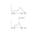
近年、LCD(Liquid Crystal Display)、EL、プラズマディスプレイ、CRT(Cathode Ray Tube)、プロジェクタ等の光学表示装置における画質改善は目覚しく、解像度、色域については人間の視覚特性にほぼ匹敵する性能が実現されつつある。しかしながら、輝度ダイナミックレンジについてみると、その再現範囲は、たかだか1〜102[nit]程度にとどまり、また、階調数は、8ビットが一般的である。一方、人間の視覚は、一度に知覚し得る輝度ダイナミックレンジが10-2〜104[nit]程度であり、また、輝度弁別能力は、0.2[nit]程度で、これを階調数に換算すると、12ビット相当といわれている。このような視覚特性を通じて現在の光学表示装置の表示画像をみると、輝度ダイナミックレンジの狭さが目立ち、加えてシャドウ部やハイライト部の階調が不足しているため表示画像のリアリティさや迫力に対して物足りなさを感じることになる。 In recent years, LCD (Liquid Crystal Display), EL, plasma display, CRT (Cathode Ray Tube), projectors, and other optical display devices have seen remarkable improvements in image quality, and the resolution and color gamut have achieved performance that is almost comparable to human visual characteristics. It is being done. However, regarding the luminance dynamic range, the reproduction range is limited to about 1 to 10 2 [nit], and the number of gradations is generally 8 bits. On the other hand, human visual perception has a luminance dynamic range perceived at a time of about 10 −2 to 10 4 [nit], and the luminance discrimination capability is about 0.2 [nit], which is the number of gradations. Is converted to 12 bits. Looking at the display image of the current optical display device through such visual characteristics, the narrowness of the luminance dynamic range is conspicuous, and in addition, the reality and power of the display image are insufficient due to the lack of gradation in the shadow part and highlight part. Will feel unsatisfactory.
また、映画やゲーム等で使用されるコンピュータグラフィックス(以下、CGと略記する。)では、人間の視覚に近い輝度ダイナミックレンジや階調数を表示データ(以下、HDR(High Dynamic Range)表示データという。)に持たせて描写のリアリティを追求する動きが主流になりつつある。しかしながら、それを表示する光学表示装置の性能が不足しているため、CGコンテンツが本来有する表現力を充分に発揮することができないという課題がある。 Further, in computer graphics (hereinafter abbreviated as CG) used in movies, games, etc., display data (hereinafter referred to as HDR (High Dynamic Range) display data) that represents a luminance dynamic range and gradation number close to human vision. The movement of pursuing the reality of depiction is being mainstream. However, since the performance of the optical display device that displays it is insufficient, there is a problem that the expressive power inherent in the CG content cannot be fully exhibited.
さらに、次期OS(Operating System)においては、16ビット色空間の採用が予定されており、現在の8ビット色空間と比較して輝度ダイナミックレンジや階調数が飛躍的に増大する。そのため、16ビット色空間を生かすことができる光学表示装置の実現が望まれる。
光学表示装置のなかでも、液晶プロジェクタ、DLP(Digital Light Processing、TI社の商標)プロジェクタといった投射型表示装置は、大画面表示が可能であり、表示画像のリアリティさや迫力を再現する上で効果的な装置である。この分野では、上記の課題を解決するために、次のような提案がなされている。
Further, in the next OS (Operating System), the adoption of a 16-bit color space is planned, and the luminance dynamic range and the number of gradations are dramatically increased as compared with the current 8-bit color space. Therefore, it is desired to realize an optical display device that can make use of the 16-bit color space.
Among optical display devices, projection display devices such as liquid crystal projectors and DLP (Digital Light Processing, trademark of TI) projectors are capable of displaying large screens and are effective in reproducing the reality and power of displayed images. Device. In this field, the following proposals have been made to solve the above problems.
高ダイナミックレンジの投射型表示装置としては、例えば、特許文献1、特許文献2及び非特許文献1に開示されている技術があり、光源と、光の全波長領域の輝度を変調する第1光変調素子と、光の波長領域のうちRGB3原色の各波長領域についてその波長領域の輝度を変調する第2光変調素子とを備え、光源からの光を第1光変調素子で変調して所望の輝度分布を形成し、その光学像を第2光変調素子の表示面に結像して色変調し、2次変調した光を投射するというものである。第1光変調素子および第2光変調素子の各画素は、HDR表示データから決定される第1制御値および第2制御値に基づいてそれぞれ別個に制御される。光変調素子としては、透過率が独立に制御可能な画素構造またはセグメント構造を有し、二次元的な透過率分布を制御し得る透過率変調素子が用いられる。その代表例としては、液晶ライトバルブが挙げられる。また、透過率変調素子の代わりに反射率変調素子を用いてもよく、その代表例としては、DMD(Digital Micromirror Device)が挙げられる。
As a high dynamic range projection display device, for example, there are technologies disclosed in
いま、暗表示の透過率が0.2%、明表示の透過率が60%の光変調素子を使用する場合を考える。光変調素子単体では、輝度ダイナミックレンジは、60/0.2=300となる。上記従来の投射型表示装置は、輝度ダイナミックレンジが300の光変調素子を光学的に直列に配置することに相当するので、300×300=90000の輝度ダイナミックレンジを実現することができる。また、階調数についてもこれと同等の考えが成り立ち、8ビット階調の光変調素子を光学的に直列に配置することにより、8ビットを超える階調数を得ることができる。 Consider a case where a light modulation element having a dark display transmittance of 0.2% and a bright display transmittance of 60% is used. With a single light modulation element, the luminance dynamic range is 60 / 0.2 = 300. Since the conventional projection display apparatus corresponds to optically arranging light modulation elements having a luminance dynamic range of 300 in series, a luminance dynamic range of 300 × 300 = 90000 can be realized. The same idea holds for the number of gradations, and an 8-bit gradation light modulation element is optically arranged in series, whereby a gradation number exceeding 8 bits can be obtained.
またその他に、高い輝度ダイナミックレンジを実現する投射型表示装置としては、例えば、非特許文献1に開示されている投射型表示装置、および特許文献2に開示されている表示装置が知られている。
非特許文献1および特許文献2記載の発明とも、第1光変調素子としてLCDを、第2光変調素子としてLEDまたは蛍光灯等の変調可能な照明を用いている。
In the inventions described in Non-Patent
しかしながら、HDR表示データは、従来のsRGB等の画像フォーマットでは実現できない高い輝度ダイナミックレンジを実現することができる画像データであり、画素の輝度レベルを示す画素値を画像の全画素について格納している。HDR表示データにおける画素pの輝度レベルをRp、第1光変調素子の画素pに対応する画素の透過率をT1、第2光変調素子の画素pに対応する画素の透過率をT2とすると、下式(1),(2)が成立する。
Rp = Tp×Rs …(1)
Tp = T1×T2×G …(2)
ただし、上式(1),(2)において、Rsは光源の輝度、Gはゲインであり、いずれも定数である。また、Tpは、光変調率である。
However, the HDR display data is image data that can achieve a high luminance dynamic range that cannot be realized by a conventional image format such as sRGB, and stores pixel values indicating the luminance level of pixels for all the pixels of the image. . When the luminance level of the pixel p in the HDR display data is Rp, the transmittance of the pixel corresponding to the pixel p of the first light modulation element is T1, and the transmittance of the pixel corresponding to the pixel p of the second light modulation element is T2. The following expressions (1) and (2) hold.
Rp = Tp × Rs (1)
Tp = T1 × T2 × G (2)
However, in the above formulas (1) and (2), Rs is the luminance of the light source, G is the gain, and both are constants. Tp is a light modulation rate.
上式(1),(2)から、画素pについてT1およびT2の組み合わせが無数に存在することが分かる。しかしながら、T1およびT2を任意に決定してよいわけではない。決定の仕方によっては画質が劣化することがあるので、T1およびT2は、画質を考慮して適切に決定する必要がある。
非特許文献1記載の発明にあっては、2つの光変調素子を用いた場合に高い輝度ダイナミックレンジを実現できることを概念的に説明するにとどまり、HDR表示データに基づいて第1光変調素子および第2光変調素子の各画素の制御値(すなわち、T1およびT2)をどのように決定し、またその制御値を用いてどのように制御するかについてまでは開示されていない。したがって、T1およびT2の決定の仕方及び決定した制御値による制御の仕方によっては画質が劣化するという問題があった。
From the above equations (1) and (2), it can be seen that there are an infinite number of combinations of T1 and T2 for the pixel p. However, T1 and T2 may not be arbitrarily determined. Since the image quality may deteriorate depending on the method of determination, T1 and T2 need to be appropriately determined in consideration of the image quality.
In the invention described in Non-Patent
一方、特許文献2記載の発明にあっては、バックライトの輝度制御及びLCDの透過率制御により輝度ダイナミックレンジの拡大を実現する方法については詳しく述べているが、第1光変調素子と第2光変調素子に前記したバックライトとLCDとの組み合わせとは異なるものを用いた他の構成や、第1光変調素子と第2光変調素子の解像度が異なる構成については輝度ダイナミックレンジの拡大を実現する具体的な方法が述べられていない。 On the other hand, in the invention described in Patent Document 2, a method for realizing the expansion of the luminance dynamic range by controlling the luminance of the backlight and the transmittance of the LCD is described in detail. The brightness dynamic range can be expanded for other configurations using different combinations of backlight and LCD for the light modulator and configurations with different resolutions of the first and second light modulators. The specific method to do is not described.
そこで、本発明は、このような従来の技術の有する未解決の課題に着目してなされたものであって、第1光変調素子と第2光変調素子とを介して2段階で光源からの光を変調することで表示画像の輝度ダイナミックレンジ及び階調数を拡大し、画質を向上するとともに、第1光変調素子よりも解像度の高い第2光変調素子の解像度に合わせて画像を表示するのに好適な光変調装置、光学表示装置、光変調制御プログラム及び光学表示装置制御プログラム、並びに光変調制御方法及び光学表示装置制御方法を提供することを目的としている。 Therefore, the present invention has been made by paying attention to such an unsolved problem of the conventional technology, and from the light source in two stages through the first light modulation element and the second light modulation element. By modulating the light, the luminance dynamic range and the number of gradations of the display image are expanded, the image quality is improved, and the image is displayed in accordance with the resolution of the second light modulation element having a higher resolution than the first light modulation element. It is an object of the present invention to provide a light modulation device, an optical display device, a light modulation control program, an optical display device control program, a light modulation control method, and an optical display device control method suitable for the above.
〔発明1〕 上記目的を達成するために、発明1の光変調装置は、光伝搬特性を独立に制御可能な複数の画素を有する第1光変調素子と、光伝搬特性を独立に制御可能で且つ前記第1光変調素子より多数の画素を有する第2光変調素子とを備え、前記第1光変調素子の画素と前記第2光変調素子の画素を1:n(nは2以上の整数)で光学的に対応させ、前記第1光変調素子及び前記第2光変調素子を介して光源からの光を変調する光学系に適用される装置であって、
前記第2光変調素子のn個の画素のうちその一部を所定の光伝搬特性とし残部を光の伝搬効率が最低又は略最低となる光伝搬特性にした制御パターンを複数種設定し、
前記第1光変調素子の1個の画素に対応する前記第2光変調素子のn個の画素を前記複数種の制御パターンのいずれかで制御するとともに、前記第1光変調素子の画素の光伝搬特性の切換タイミングに合わせて、前記第2光変調素子の画素の制御パターンを切り換えるようになっていることを特徴としている。
[Invention 1] In order to achieve the above object, the light modulation device of
A plurality of control patterns in which some of the n pixels of the second light modulation element have predetermined light propagation characteristics and the remaining light propagation characteristics have the lowest or substantially the lowest light propagation efficiency are set;
The n pixels of the second light modulation element corresponding to one pixel of the first light modulation element are controlled by any one of the plurality of types of control patterns, and the light of the pixels of the first light modulation element is also controlled. The control pattern of the pixel of the second light modulation element is switched in accordance with the switching timing of the propagation characteristic.
このような構成であれば、前記第1光変調素子の1個の画素に対応する前記第2光変調素子のn個の画素を前記複数種の制御パターンのいずれかで制御するとともに、前記第1光変調素子の画素の光伝搬特性の切換タイミングに合わせて、前記第2光変調素子の画素の制御パターンを切り換えることが可能である。
従って、第2光変調素子における、第1光変調素子の各画素に対応するn個の画素の光伝搬特性を、第1光変調素子の各画素の切換えタイミングに合わせて各画素毎に適切な光伝搬特性に切り換えることによって、第2光変調素子の有する解像度(画素数)の光によって形成される光学像を目的位置に伝達できるという効果が得られる。
With such a configuration, the n pixels of the second light modulation element corresponding to one pixel of the first light modulation element are controlled by any one of the plurality of types of control patterns, and the first The control pattern of the pixel of the second light modulation element can be switched in accordance with the switching timing of the light propagation characteristic of the pixel of the one light modulation element.
Accordingly, the light propagation characteristics of the n pixels corresponding to the pixels of the first light modulation element in the second light modulation element are appropriately set for each pixel in accordance with the switching timing of the pixels of the first light modulation element. By switching to the light propagation characteristics, it is possible to obtain an effect that an optical image formed by light having the resolution (number of pixels) of the second light modulation element can be transmitted to the target position.
また、第1光変調素子および第2光変調素子により光源の光を2段階に変調するので、比較的高い輝度ダイナミックレンジおよび階調数を実現することができるという効果が得られる。
ここで、光伝搬特性とは、光の伝搬に影響を与える特性をいい、例えば、光の透過特性、反射特性、屈折特性その他の伝搬特性が含まれる。以下、発明2の光学表示装置、発明12及び13の光変調装置、発明14、24及び25の光変調制御プログラム、発明15の光学表示装置制御プログラム、発明26、37及び38の光変調制御方法、並びに、発明27の光学表示装置制御方法において同じである。
In addition, since the light from the light source is modulated in two stages by the first light modulation element and the second light modulation element, an effect that a relatively high luminance dynamic range and number of gradations can be realized is obtained.
Here, the light propagation characteristics refer to characteristics that affect light propagation, and include, for example, light transmission characteristics, reflection characteristics, refraction characteristics, and other propagation characteristics. Hereinafter, the optical display device of the invention 2, the light modulation device of the
また、光変調素子は、上記したように画素毎の透過率や反射率等の光伝搬特性を制御可能な液晶ライトバルブやDMD等の素子を含む。以下、発明2の光学表示装置、発明12及び13の光変調装置、発明14、24及び25の光変調制御プログラム、発明15の光学表示装置制御プログラム、発明26、37及び38の光変調制御方法、並びに、発明27の光学表示装置制御方法において同じである。
Further, the light modulation element includes an element such as a liquid crystal light valve or a DMD capable of controlling light propagation characteristics such as transmittance and reflectance for each pixel as described above. Hereinafter, the optical display device of the invention 2, the light modulation device of the
また、第2光変調素子のn個の画素に対する複数種の制御パターンは、第2光変調素子のn個の画素全ての光伝搬効率が最低又は略最低となる光伝搬特性に切り換える組み合わせも含む。以下、発明2の光学表示装置、発明12の光変調制御プログラム、発明13の光学表示装置制御プログラム、発明26の光変調制御方法及び発明27の光学表示装置制御方法において同じである。
In addition, the plurality of types of control patterns for the n pixels of the second light modulation element include a combination for switching to the light propagation characteristic that the light propagation efficiency of all the n pixels of the second light modulation element is the lowest or substantially the lowest. . The same applies to the optical display device of the invention 2, the light modulation control program of the
〔発明2〕 一方、上記目的を達成するために、発明2の光学表示装置は、光伝搬特性を独立に制御可能な複数の画素を有する第1光変調素子と、光伝搬特性を独立に制御可能な複数の画素を有する第2光変調素子とを備え、前記第1光変調素子の画素と前記第2光変調素子の画素を1:n(nは2以上の整数)で光学的に対応させ、前記第1光変調素子及び前記第2光変調素子を介して光源からの光を変調して画像を表示する装置であって、
表示画像データのうち1の画素に対応する画素値を、前記第1光変調素子制御用の画素値及び前記第2光変調素子制御用の画素値にそれぞれ区分し、前記第1光変調素子制御用の画素値をさらに複数の原始画素値に区分し、
前記第2光変調素子制御用の画素値に基づき前記第2光変調素子のn個の画素のうちその一部を所定の光伝搬特性とし残部を光の伝搬効率が最低又は略最低となる光伝搬特性にした制御パターンを複数種設定し、
前記第1光変調素子制御用の各原始画素値に基づいて前記第1光変調素子の画素の光伝搬特性を時分割に切換制御する第1光伝搬特性制御手段と、
前記第1光変調素子の画素の光伝搬特性の切換タイミングに合わせて、前記第2光変調素子の画素の制御パターンを切換制御する第2光伝搬特性制御手段と、を備えることを特徴としている。
[Invention 2] On the other hand, in order to achieve the above object, the optical display device of Invention 2 independently controls the first light modulation element having a plurality of pixels whose light propagation characteristics can be controlled independently, and the light propagation characteristics. A second light modulation element having a plurality of possible pixels, and optically corresponding the pixel of the first light modulation element and the pixel of the second light modulation element by 1: n (n is an integer of 2 or more) And an apparatus for displaying an image by modulating light from a light source via the first light modulation element and the second light modulation element,
A pixel value corresponding to one pixel in the display image data is divided into a pixel value for controlling the first light modulation element and a pixel value for controlling the second light modulation element, respectively, and the first light modulation element control is performed. The pixel value for the image is further divided into a plurality of primitive pixel values,
Based on the pixel value for controlling the second light modulation element, a part of the n pixels of the second light modulation element has a predetermined light propagation characteristic, and the remaining light has the lowest or substantially the lowest light propagation efficiency. Set multiple types of control patterns with propagation characteristics,
First light propagation characteristic control means for switching and controlling the light propagation characteristics of the pixels of the first light modulation element in a time-sharing manner based on the respective primitive pixel values for controlling the first light modulation element;
And second light propagation characteristic control means for switching and controlling the control pattern of the pixel of the second light modulation element in accordance with the switching timing of the light propagation characteristic of the pixel of the first light modulation element. .
このような構成であれば、第1光伝搬特性制御手段によって前記第1光変調素子制御用の各原始画素値に基づいて前記第1光変調素子の画素の光伝搬特性を時分割に切換制御することが可能であり、第2光伝搬特性制御手段によって前記第1光変調素子の画素の光伝搬特性の切換タイミングに合わせて、前記第2光変調素子の画素の制御パターンを切換制御することが可能である。 With such a configuration, the first light propagation characteristic control means switches the light propagation characteristics of the pixels of the first light modulation element in a time-sharing manner based on each primitive pixel value for controlling the first light modulation element. The second light propagation characteristic control means switches the control pattern of the pixel of the second light modulation element in accordance with the switching timing of the light propagation characteristic of the pixel of the first light modulation element. Is possible.
従って、表示画像データに基づき第1光変調素子の各画素の切り換えタイミングに合わせて、第2光変調素子のn個の画素の光伝搬特性の制御パターンを高速且つ時分割で切り換えることで、第2光変調素子の有する解像度で表示画像データの画像を表示することができるという効果が得られる。
また、第1光変調素子および第2光変調素子により光源の光を2段階に変調するので、比較的高い輝度ダイナミックレンジおよび階調数を実現することができるという効果が得られる。
Therefore, by switching the control pattern of the light propagation characteristics of the n pixels of the second light modulation element at high speed and in time division according to the switching timing of each pixel of the first light modulation element based on the display image data, The effect that the image of display image data can be displayed with the resolution which 2 light modulation element has is acquired.
In addition, since the light from the light source is modulated in two stages by the first light modulation element and the second light modulation element, an effect that a relatively high luminance dynamic range and number of gradations can be realized is obtained.
ここで、原始画素値とは、画像の色情報を示す値であり、例えば、表示画像データの画素値が光の3原色であるR(赤),G(緑),B(青)の3つの色情報の値を含んでいる場合は、これらR,G,Bの各値を示す。以下、発明15の光学表示装置制御プログラム及び発明27の光学表示装置制御方法において同じである。
Here, the primitive pixel value is a value indicating the color information of the image. For example, the pixel value of the display image data is 3 (R (red), G (green), and B (blue)), which are the three primary colors of light. When one color information value is included, each of these R, G, and B values is indicated. Hereinafter, the same applies to the optical display device control program of the
〔発明3〕 さらに、発明3の光学表示装置は、発明2の光学表示装置において、前記第1光変調素子の1画素に対応する前記第2光変調素子のn個の画素に対する前記画素値が全て同じ値であるときに、
前記第1光伝搬特性制御手段は、前記第1光変調素子の各画素の光伝搬特性を前記画素値をさらに区分した複数の原始画素値に基づく光伝搬特性に切り換え、且つ、当該切り換えた光伝搬特性を前記n個の画素の制御に応じた時間維持するようになっており、
前記第2光伝搬特性制御手段は、前記第1光変調素子の各画素の切換タイミングに合わせて、前記n個の画素の光伝搬特性を前記画素値に基づく光伝搬特性に切換制御するようになっていることを特徴としている。
[Invention 3] Furthermore, in the optical display device of
The first light propagation characteristic control means switches the light propagation characteristic of each pixel of the first light modulation element to a light propagation characteristic based on a plurality of primitive pixel values obtained by further dividing the pixel value, and the switched light Propagation characteristics are maintained for a time according to the control of the n pixels,
The second light propagation characteristic control means switches and controls the light propagation characteristic of the n pixels to the light propagation characteristic based on the pixel value in accordance with the switching timing of each pixel of the first light modulation element. It is characterized by becoming.
このような構成であれば、前記第1光伝搬特性制御手段は、前記第1光変調素子の各画素の光伝搬特性を前記画素値をさらに区分した複数の原始画素値に基づく光伝搬特性に切り換え、且つ、当該切り換えた光伝搬特性を前記n個の画素の制御に応じた時間維持することが可能であり、前記第2光伝搬特性制御手段は、前記第1光変調素子の各画素の切換タイミングに合わせて、前記n個の画素の光伝搬特性を前記画素値に基づく光伝搬特性に切換制御することが可能である。 With such a configuration, the first light propagation characteristic control means converts the light propagation characteristic of each pixel of the first light modulation element into a light propagation characteristic based on a plurality of primitive pixel values obtained by further dividing the pixel value. It is possible to switch and maintain the switched light propagation characteristics for a time corresponding to the control of the n pixels, and the second light propagation characteristic control means is configured to control each pixel of the first light modulation element. It is possible to switch and control the light propagation characteristics of the n pixels to the light propagation characteristics based on the pixel values in accordance with the switching timing.
従って、n個の画素に対応する表示画像データの画素値が全て同じ値であるときに、第1光変調素子及び第2光変調素子の対応する各画素の光伝搬特性の切り換え回数を減らすことができるので処理負荷を低減できると共に、対応する画素部分の時分割切換制御による輝度低下を防ぐことができるという効果が得られる。 Therefore, when the pixel values of the display image data corresponding to the n pixels are all the same value, the number of switching of the light propagation characteristics of the corresponding pixels of the first light modulation element and the second light modulation element is reduced. Therefore, it is possible to reduce the processing load and to prevent the decrease in luminance due to the time division switching control of the corresponding pixel portion.
〔発明4〕 さらに、発明4の光学表示装置は、発明2又は発明3の光学表示装置において、前記第1光伝搬特性制御手段及び第2光伝搬特性制御手段は、表示する画像が静止画像であるときに前記切換制御を行うようになっていることを特徴としている。
このような構成であれば、前記第1光伝搬特性制御手段及び第2光伝搬特性制御手段は、表示する画像が静止画像であるきに前記切換制御を行う。
[Invention 4] Furthermore, the optical display device of Invention 4 is the optical display device of Invention 2 or
With such a configuration, the first light propagation characteristic control unit and the second light propagation characteristic control unit perform the switching control when the image to be displayed is a still image.
従って、表示画像データが静止画像のときだけ上記切換制御を行い、一方、表示画像データが動画像であった場合は第1光変調素子の画素と第2光変調素子の画素とを一対一に対応させて、第1光変調素子の解像度で画像を表示するうようにすることで、表示画像が動画像のときには処理負荷を軽減でき、一方、表示画像が静止画像のときは高画質で画像を表示できるという効果が得られる。
ここで、静止画とは、画像データ自体が静止画である場合に限らず、動画データ中において、ある領域のデータが変化しない場合も静止画として含む。
Therefore, the above switching control is performed only when the display image data is a still image. On the other hand, when the display image data is a moving image, the pixels of the first light modulation element and the pixels of the second light modulation element are in a one-to-one relationship. Correspondingly, by displaying the image at the resolution of the first light modulation element, the processing load can be reduced when the display image is a moving image, while the display image is a high quality image when the display image is a still image. The effect that can be displayed is obtained.
Here, the still image includes not only a case where the image data itself is a still image but also a case where the data in a certain area does not change in the moving image data.
〔発明5〕 さらに、発明5の光学表示装置は、発明2乃至発明4のいずれか1の光学表示装置において、前記第1光伝搬特性制御手段は、前記表示画像データに基づき前記第1光変調素子の各画素における前記原始画素値に応じた光伝搬特性を、当該各画素に対応する前記第2光変調素子の画素の光の伝搬効率よりも高い伝搬効率となる特性に切り換えるようになっていることを特徴としている。 [Invention 5] The optical display device according to Invention 5 is the optical display device according to any one of Inventions 2 to 4, wherein the first light propagation characteristic control means is based on the display image data. The light propagation characteristic corresponding to the primitive pixel value in each pixel of the element is switched to a characteristic having a propagation efficiency higher than the light propagation efficiency of the pixel of the second light modulation element corresponding to each pixel. It is characterized by being.
このような構成であれば、前記第1光伝搬特性制御手段は、前記表示画像データに基づき前記第1光変調素子の各画素における前記原始画素値に応じた光伝搬特性を、当該各画素に対応する前記第2光変調素子の画素の光の伝搬効率よりも高い伝搬効率となる特性に切換えることが可能である。
従って、上記時分割の切換制御によって低下する表示画像の輝度を第1光変調素子の各画素の光伝搬効率を高めることにより補うことができるという効果が得られる。
With such a configuration, the first light propagation characteristic control means provides each pixel with a light propagation characteristic corresponding to the original pixel value in each pixel of the first light modulation element based on the display image data. It is possible to switch to a characteristic having a propagation efficiency higher than the light propagation efficiency of the pixel of the corresponding second light modulation element.
Therefore, it is possible to compensate for the luminance of the display image, which is reduced by the time-division switching control, by increasing the light propagation efficiency of each pixel of the first light modulation element.
〔発明6〕 さらに、発明6の光学表示装置は、発明2乃至発明4のいずれか1の光学表示装置において、前記第2光伝搬特性制御手段は、前記表示画像データに基づき前記第2光変調素子における画素の前記第2光変調素子制御用の画素値に応じた光伝搬特性を、当該画素に対応する前記第1光変調素子の画素の光の伝搬効率よりも高い伝搬効率となる特性に切り換えることを特徴としている。 [Invention 6] The optical display device according to Invention 6 is the optical display device according to any one of Inventions 2 to 4, wherein the second light propagation characteristic control means is based on the display image data. The light propagation characteristic corresponding to the pixel value for controlling the second light modulation element of the pixel in the element is set to a characteristic that has a higher propagation efficiency than the light propagation efficiency of the pixel of the first light modulation element corresponding to the pixel. It is characterized by switching.
このような構成であれば、前記第2光伝搬特性制御手段は、前記表示画像データに基づき前記第2光変調素子における画素の前記第2光変調素子制御用の画素値に応じた光伝搬特性を、当該画素に対応する前記第1光変調素子の画素の光の伝搬効率よりも高い伝搬効率となる特性に切り換えることが可能である。
従って、上記時分割の切換制御によって低下する表示画像の輝度を第2光変調素子の画素の光伝搬効率を高めることにより補うことができるという効果が得られる。
With such a configuration, the second light propagation characteristic control means has a light propagation characteristic corresponding to the pixel value for controlling the second light modulation element of the pixel in the second light modulation element based on the display image data. Can be switched to a characteristic having a propagation efficiency higher than the light propagation efficiency of the pixel of the first light modulation element corresponding to the pixel.
Therefore, it is possible to compensate for the luminance of the display image, which is reduced by the time-division switching control, by increasing the light propagation efficiency of the pixels of the second light modulation element.
〔発明7〕 さらに、発明7の光学表示装置は、発明2乃至発明6のいずれか1の光学表示装置において、前記第1光変調素子及び前記第2光変調素子は共に前記画素がマトリクス状に配列された構成となっており、前記第2光変調素子の画素数が、前記第1光変調素子の画素数に対して行方向及び列方向共に整数倍であり、前記第1光変調素子の各画素毎に、当該画素と前記第2光変調素子のn個の画素とが規則的に且つ光学的に対応していることを特徴としている。 [Invention 7] The optical display device according to Invention 7 is the optical display device according to any one of Inventions 2 to 6, wherein the first light modulation element and the second light modulation element are both arranged in a matrix. The number of pixels of the second light modulation element is an integer multiple of the number of pixels of the first light modulation element in both the row direction and the column direction. For each pixel, the pixel and the n pixels of the second light modulation element regularly and optically correspond to each other.
このような構成であれば、第1光変調素子の各画素と第2光変調素子のn個の画素とが規則的に対応しているので、切り換え処理を簡易に行うことが可能となり、処理の高速化に加え、回路構成及び光学構成の簡略化などによるコストの低減ができるという効果が得られる。 With such a configuration, each pixel of the first light modulation element and the n pixels of the second light modulation element regularly correspond to each other, so that the switching process can be easily performed. In addition to speeding up, it is possible to reduce the cost by simplifying the circuit configuration and the optical configuration.
〔発明8〕 さらに、発明8の光学表示装置は、発明7の光学表示装置において、異なる複数の波長領域の光に対応した複数の前記第1光変調素子を備え、
前記各第1光変調素子の各画素毎に、当該画素と前記第2光変調素子のn個の画素とが規則的に且つ光学的に対応していることを特徴としている。
[Invention 8] Further, the optical display device of Invention 8 is the optical display device of Invention 7, comprising a plurality of the first light modulation elements corresponding to light of a plurality of different wavelength regions,
For each pixel of each of the first light modulation elements, the pixel and the n pixels of the second light modulation element regularly and optically correspond to each other.
このような構成であれば、例えば、光の3原色の各色光のように波長領域の異なる複数の光にそれぞれ対応した複数の第1光変調素子の各画素と、第2光変調素子のn個の画素とが規則的に対応するので、カラー画像の表示において、例えば、第1光変調素子を1つにして回転型のカラーフィルタ等で構成するような場合に比べ、3つの色光を第1光変調素子で別々に変調することができるので、処理速度を向上でき、また、第2光変調素子として従来の液晶表示素子(LCD、液晶ライトバルブ等)を転用できるのでコストを低減することができるという効果が得られる。 With such a configuration, for example, each pixel of a plurality of first light modulation elements respectively corresponding to a plurality of lights having different wavelength regions such as light of three primary colors of light, and n of the second light modulation element Since the pixels regularly correspond to each other, in the display of the color image, for example, compared with the case where the first light modulation element is used and the rotation type color filter is used, the three color lights are used as the first color light. Since the light can be separately modulated by one light modulation element, the processing speed can be improved, and a conventional liquid crystal display element (LCD, liquid crystal light valve, etc.) can be diverted as the second light modulation element, thereby reducing costs. The effect of being able to be obtained.
〔発明9〕 さらに、発明9の光学表示装置は、発明7又は8の光学表示装置において、前記第2光変調素子の列方向の画素数が、前記第1光変調素子の列方向の画素数の2倍であり、
前記第2光伝搬特性切換手段は、前記第2光変調素子の偶数行及び奇数行のいずれか一方から順番に前記表示画像データの画素値に対応する光伝搬特性の前記切換処理を行い、当該切換処理が行われている間は他方の行の画素の光伝搬特性を光の伝搬効率が最低又は略最低となる特性に切り換えるようになっていることを特徴としている。
[Invention 9] The optical display device of Invention 9 is the optical display device of Invention 7 or 8, wherein the number of pixels in the column direction of the second light modulation element is the number of pixels in the column direction of the first light modulation element. 2 times,
The second light propagation characteristic switching means performs the switching process of the light propagation characteristic corresponding to the pixel value of the display image data in order from either one of the even-numbered row and the odd-numbered row of the second light modulation element, While the switching process is being performed, the light propagation characteristics of the pixels in the other row are switched to a characteristic that minimizes or substantially minimizes the light propagation efficiency.
このような構成であれば、前記第2光伝搬特性制御手段は、前記第2光変調素子の偶数行及び奇数行のいずれか一方の画素から順番に前記切換制御を行い、当該切換制御が行われている間は他方の行の画素の光伝搬特性を光の伝搬効率が最低又は略最低となる特性に切り換えることが可能である。
従って、第2光変調素子において、インターレース走査と同様の手順で光の変調処理を行うことができるので、表示解像度が2倍になっても1倍速動作を2回行うことで画像の表示を行うことができるので、回路構成や光学構成の簡易化によるコスト低減ができるという効果が得られる。
With such a configuration, the second light propagation characteristic control means performs the switching control in order from one of the even-numbered and odd-numbered pixels of the second light modulation element, and the switching control is performed. During this time, it is possible to switch the light propagation characteristics of the pixels in the other row to a characteristic in which the light propagation efficiency is the lowest or substantially the lowest.
Therefore, the second light modulation element can perform light modulation processing in the same procedure as the interlaced scanning. Therefore, even if the display resolution is doubled, the image is displayed by performing the 1 × speed operation twice. Therefore, the cost can be reduced by simplifying the circuit configuration and the optical configuration.
また、インターレース走査と同様の手順により画像を表示するので、動画像の表示品質を向上することができるという効果が得られる。
また、インターレース信号とのマッチングが良くなるためインターレース映像信号による画像表示時の画質が向上する。
In addition, since the image is displayed by the same procedure as the interlace scanning, an effect that the display quality of the moving image can be improved is obtained.
In addition, since the matching with the interlace signal is improved, the image quality at the time of image display by the interlace video signal is improved.
〔発明10〕 さらに、発明10の光学表示装置は、発明7又は8の光学表示装置において、前記第2光変調素子の行方向の画素数が、前記第1光変調素子の行方向の画素数の2倍であり、
前記第2光伝搬特性切換手段は、前記第2光変調素子の偶数列及び奇数列のいずれか一方から順番に前記表示画像データの画素値に対応する光伝搬特性の前記切換処理を行い、当該切換処理が行われている間は他方の列の画素の光伝搬特性を光の伝搬効率が最低又は略最低となる特性に切り換えるようになっていることを特徴としている。
[Invention 10] The optical display device of
The second light propagation characteristic switching means performs the switching process of the light propagation characteristic corresponding to the pixel value of the display image data in order from either one of the even-numbered column and the odd-numbered column of the second light modulation element, While the switching process is being performed, the light propagation characteristics of the pixels in the other column are switched to a characteristic in which the light propagation efficiency is the lowest or substantially the lowest.
このような構成であれば、前記第2光伝搬特性制御手段は、前記第2光変調素子の偶数列及び奇数列のいずれか一方の画素から順番に前記切換制御を行い、当該切換制御が行われている間は他方の列の画素の光伝搬特性を光の伝搬効率が最低又は略最低となる特性に切り換えることが可能である。
従って、第2光変調素子において、インターレース走査と同様の手順で光の変調処理を行うことができるので、表示解像度が2倍になっても1倍速動作を2回行うことで画像の表示を行うことができるので、回路構成や光学構成の簡易化によるコスト低減ができるという効果が得られる。
With such a configuration, the second light propagation characteristic control means performs the switching control in order from one of the even-numbered and odd-numbered pixels of the second light modulation element, and the switching control is performed. During this time, it is possible to switch the light propagation characteristics of the pixels in the other column to a characteristic in which the light propagation efficiency is lowest or substantially lowest.
Therefore, the second light modulation element can perform light modulation processing in the same procedure as the interlaced scanning. Therefore, even if the display resolution is doubled, the image is displayed by performing the 1 × speed operation twice. Therefore, the cost can be reduced by simplifying the circuit configuration and the optical configuration.
また、インターレース走査と同様の手順により画像を表示するので、動画像の表示品質を向上することができるという効果が得られる。
また、インターレース信号とのマッチングが良くなるためインターレース映像信号による画像表示時の画質が向上する。
In addition, since the image is displayed by the same procedure as the interlace scanning, an effect that the display quality of the moving image can be improved is obtained.
In addition, since the matching with the interlace signal is improved, the image quality at the time of image display by the interlace video signal is improved.
〔発明11〕 さらに、発明11の光学表示装置は、発明2乃至発明10のいずれか1の光学表示装置において、前記第2光変調素子は液晶表示素子であることを特徴としている。
このような構成であれば、第2光変調素子として、従来のカラーフィルタ付きのLCDパネルからカラーフィルタを取り外したものを転用したり、従来のカラーフィルタ付きLCDのカラーフィルタをモノクロフィルタに交換したものを転用したりできるので、コストを低減できるという効果が得られる。
[Invention 11] The optical display device of Invention 11 is characterized in that in the optical display device of any one of Inventions 2 to 10, the second light modulation element is a liquid crystal display element.
In such a configuration, the second light modulation element can be diverted from a conventional LCD panel with a color filter and the color filter of the conventional LCD with a color filter is replaced with a monochrome filter. Since a thing can be diverted, the effect that cost can be reduced is acquired.
〔発明12〕 一方、上記目的を達成するために、発明12の光変調装置は、光伝搬特性を独立に制御可能な複数の画素を有する光変調素子と、輝度を独立に調整可能な複数の光源を有する輝度調整光源とを備え、前記光変調素子の画素と前記輝度調整光源の光源を1:n(nは2以上の整数)で光学的に対応させ、前記光変調素子を介して前記輝度調整光源からの光を変調する光学系に適用される装置であって、
前記輝度調整光源のn個の光源のうちその一部を所定輝度で点灯し残部を非点灯とした制御パターンを複数種設定し、
前記光変調素子の1画素に対応する前記輝度調整光源のn個の光源を前記複数種の制御パターンのうちいずれかで制御するとともに、前記光変調素子の各画素の光伝搬特性の切換タイミングに合わせて、前記各画素に対応する前記輝度変調光源のn個の光源の制御パターンを切り換えるようになっていることを特徴としている。
[Invention 12] On the other hand, in order to achieve the above object, the light modulation device of
A plurality of control patterns in which a part of the n light sources of the brightness adjustment light source is turned on at a predetermined brightness and the remaining part is not turned on are set.
The n light sources of the luminance adjustment light source corresponding to one pixel of the light modulation element are controlled by any one of the plurality of types of control patterns, and at the switching timing of the light propagation characteristics of each pixel of the light modulation element. In addition, the control pattern of n light sources of the luminance modulation light source corresponding to each pixel is switched.
このような構成であれば、前記光変調素子の各画素の光伝搬特性を所定特性に時分割で切り替えることが可能であり、前記各画素の光伝搬特性の切り換えタイミングに合わせて、当該各画素に対応するn個の光源の輝度を複数種の制御パターンのいずれかに切り換えることが可能である。
従って、輝度変調光源におけるn個の光源の輝度を、各画素の光伝搬特性の切換えタイミングに合わせて各光源毎に適切な制御パターンに切り換えることによって、輝度変調光源の有する解像度(光源数)の光によって形成される光学像を目的位置に伝達できるという効果が得られる。
With such a configuration, it is possible to switch the light propagation characteristic of each pixel of the light modulation element to a predetermined characteristic in a time-sharing manner, and according to the switching timing of the light propagation characteristic of each pixel, It is possible to switch the luminance of n light sources corresponding to 1 to any one of a plurality of types of control patterns.
Therefore, by switching the luminance of the n light sources in the luminance modulation light source to an appropriate control pattern for each light source in accordance with the switching timing of the light propagation characteristics of each pixel, the resolution (number of light sources) of the luminance modulation light source can be reduced. An effect is obtained that an optical image formed by light can be transmitted to a target position.
また、輝度変調光源および光変調素子により光源の光を2段階に変調するので、比較的高い輝度ダイナミックレンジおよび階調数を実現することができるという効果が得られる。
また、輝度変調光源は、LED(Light Emitting Diode)、OLED (Organic Light Emitting Diode) 、蛍光灯などの輝度を調整可能な光源により構成されたものを含む。以下、発明13の光学表示装置、発明24及び25の光変調制御プログラム、並びに、発明37及び38の光変調制御方法において同じである。
Further, since the light of the light source is modulated in two steps by the luminance modulation light source and the light modulation element, an effect that a relatively high luminance dynamic range and the number of gradations can be realized is obtained.
The luminance modulation light source includes a light source that can adjust the luminance, such as an LED (Light Emitting Diode), an OLED (Organic Light Emitting Diode), or a fluorescent lamp. The same applies to the optical display device of the thirteenth invention, the light modulation control program of the inventions 24 and 25, and the light modulation control method of the inventions 37 and 38.
また、所定数の光源に対する所定輝度への切り換え処理は、光変調素子の各画素の切り換えタイミングに合わせて、n個の光源を全て消灯する組み合わせも含む。以下、発明24の光変調制御プログラム及び発明37の光変調制御方法において同じである。 In addition, the process of switching the predetermined number of light sources to the predetermined luminance includes a combination of turning off all n light sources in accordance with the switching timing of each pixel of the light modulation element. Hereinafter, the same applies to the light modulation control program of the invention 24 and the light modulation control method of the invention 37.
〔発明13〕 一方、上記目的を達成するために、発明13の光変調装置は、輝度を独立に調整可能な複数の光源を有する輝度調整光源と、光伝搬特性を独立に制御可能な複数の画素を有する光変調素子とを備え、前記輝度調整光源の光源と前記光変調素子の画素を1:n(nは2以上の整数)で光学的に対応させ、前記光変調素子を介して前記輝度調整光源からの光を変調する光学系に適用される装置であって、
前記光変調素子のn個の画素のうちその一部を所定の光伝搬特性とし残部を光の伝搬効率が最低又は略最低となる光伝搬特性にした制御パターンを複数種設定し、
前記輝度調整光源の1個の光源に対応する前記光変調素子のn個の画素を前記複数種の制御パターンのうちいずれかで制御するとともに、前記輝度調整光源の各光源の輝度の切換タイミングに合わせて、前記各光源に対応する前記光変調素子のn個の画素の制御パターンを切り換えるようになっていることを特徴としている。
[Invention 13] On the other hand, in order to achieve the above object, the light modulation device of Invention 13 includes a luminance adjustment light source having a plurality of light sources capable of independently adjusting the luminance, and a plurality of light propagation characteristics that can be controlled independently. A light modulation element having a pixel, the light source of the luminance adjustment light source and the pixel of the light modulation element are optically associated with each other at 1: n (n is an integer of 2 or more), and the light modulation element is interposed through the light modulation element. An apparatus applied to an optical system that modulates light from a brightness adjusting light source,
A plurality of control patterns in which a part of the n pixels of the light modulation element has a predetermined light propagation characteristic and the remaining part has a light propagation characteristic at which light propagation efficiency is lowest or substantially lowest are set,
The n pixels of the light modulation element corresponding to one light source of the luminance adjustment light source are controlled by any one of the plurality of types of control patterns, and at the timing of switching the luminance of each light source of the luminance adjustment light source. In addition, the control pattern of n pixels of the light modulation element corresponding to each light source is switched.
このような構成であれば、前記輝度調整光源の各光源の輝度を時分割で切り換えることが可能であり、前記各光源の輝度の切り換えタイミングに合わせて、当該各光源に対応するn個の画素の光伝搬特性を所定特性に切り換えることが可能である。
従って、各光源に対応するn個の画素の光伝搬特性を、各光源の切換えタイミングに合わせて適切な制御パターンに切り換えることによって、光変調素子の有する解像度(画素数)の光によって形成される光学像を目的位置に伝達できるという効果が得られる。
With such a configuration, it is possible to switch the brightness of each light source of the brightness adjustment light source in a time-sharing manner, and n pixels corresponding to each light source according to the switching timing of the brightness of each light source. It is possible to switch the light propagation characteristic to a predetermined characteristic.
Accordingly, the light propagation characteristics of the n pixels corresponding to each light source are switched to an appropriate control pattern in accordance with the switching timing of each light source, thereby forming light with the resolution (number of pixels) of the light modulation element. An effect is obtained that an optical image can be transmitted to a target position.
また、輝度変調光源および光変調素子により光源の光を2段階に変調するので、比較的高い輝度ダイナミックレンジおよび階調数を実現することができるという効果が得られる。
また、複数種の制御パターンは、輝度変調光源の各光源の切り換えタイミングに合わせて、所定数の画素を全て光の伝搬効率が最低又は略最低となる光伝搬特性とする組み合わせも含む。以下、発明25の光変調制御プログラム及び発明38の光変調制御方法において同じである。
Further, since the light of the light source is modulated in two steps by the luminance modulation light source and the light modulation element, an effect that a relatively high luminance dynamic range and the number of gradations can be realized is obtained.
In addition, the plurality of types of control patterns include a combination in which a predetermined number of pixels have light propagation characteristics that make light propagation efficiency minimum or substantially minimum in accordance with the switching timing of each light source of the luminance modulation light source. Hereinafter, the same applies to the light modulation control program of the invention 25 and the light modulation control method of the invention 38.
〔発明14〕 一方、上記目的を達成するために、発明14の光変調制御プログラムは、光伝搬特性を独立に制御可能な複数の画素を有する第1光変調素子と、光伝搬特性を独立に制御可能で且つ前記第1光変調素子より多数の画素を有する第2光変調素子とを備え、前記第1光変調素子の画素と前記第2光変調素子の画素を1:n(nは2以上の整数)で光学的に対応させ、前記第1光変調素子及び前記第2光変調素子を介して光源からの光を変調する光学系に適用されるプログラムであって、
前記第2光変調素子のn個の画素のうちその一部を所定の光伝搬特性とし残部を光の伝搬効率が最低又は略最低となる光伝搬特性にした制御パターンを複数種設定し、
前記第1光変調素子の1個の画素に対応する前記第2光変調素子のn個の画素を前記複数種の制御パターンのいずれかで制御するとともに、前記第1光変調素子の画素の光伝搬特性の切換タイミングに合わせて、前記第2光変調素子の画素の制御パターンを切り換えるようになっていることを特徴としている。
[Invention 14] On the other hand, in order to achieve the above object, an optical modulation control program according to
A plurality of control patterns in which some of the n pixels of the second light modulation element have predetermined light propagation characteristics and the remaining light propagation characteristics have the lowest or substantially the lowest light propagation efficiency are set;
The n pixels of the second light modulation element corresponding to one pixel of the first light modulation element are controlled by any one of the plurality of types of control patterns, and the light of the pixels of the first light modulation element is also controlled. The control pattern of the pixel of the second light modulation element is switched in accordance with the switching timing of the propagation characteristic.
ここで、本発明は、発明1の光変調装置に適用可能なプログラムであり、これにより発明1の光変調装置と同等の効果が得られる。 Here, the present invention is a program that can be applied to the light modulation device of the first invention, and thereby, an effect equivalent to that of the light modulation device of the first invention can be obtained.
〔発明15〕 一方、上記目的を達成するために、発明15の光学表示装置制御プログラムは、光伝搬特性を独立に制御可能な複数の画素を有する第1光変調素子と、光伝搬特性を独立に制御可能な複数の画素を有する第2光変調素子とを備え、前記第1光変調素子の画素と前記第2光変調素子の画素を1:n(nは2以上の整数)で光学的に対応させ、前記第1光変調素子及び前記第2光変調素子を介して前記光源からの光を変調して画像を表示する光学表示装置を制御するためのプログラムであって、
表示画像データのうち1の画素に対応する画素値を、前記第1光変調素子制御用の画素値及び前記第2光変調素子制御用の画素値にそれぞれ区分し、前記第1光変調素子制御用の画素値をさらに複数の原始画素値に区分し、
前記第2光変調素子制御用の画素値に基づき前記第2光変調素子のn個の画素のうちその一部を所定の光伝搬特性とし残部を光の伝搬効率が最低又は略最低となる光伝搬特性にした制御パターンを複数種設定し、
前記第1光変調素子制御用の各原始画素値に基づいて前記第1光変調素子の画素の光伝搬特性を時分割に切換制御する第1光伝搬特性制御手段、及び、
前記第1光変調素子の画素の光伝搬特性の切換タイミングに合わせて、前記第2光変調素子の画素の制御パターンを切換制御する第2光伝搬特性制御手段として実現される処理をコンピュータに実行させるためのプログラムであることを特徴としている。
[Invention 15] On the other hand, in order to achieve the above object, the optical display device control program according to
A pixel value corresponding to one pixel in the display image data is divided into a pixel value for controlling the first light modulation element and a pixel value for controlling the second light modulation element, respectively, and the first light modulation element control is performed. The pixel value for the image is further divided into a plurality of primitive pixel values,
Based on the pixel value for controlling the second light modulation element, a part of the n pixels of the second light modulation element has a predetermined light propagation characteristic, and the remaining light has the lowest or substantially the lowest light propagation efficiency. Set multiple types of control patterns with propagation characteristics,
First light propagation characteristic control means for switching and controlling the light propagation characteristics of the pixels of the first light modulation element in a time-sharing manner based on each primitive pixel value for controlling the first light modulation element; and
The computer executes processing realized as second light propagation characteristic control means for switching and controlling the control pattern of the pixel of the second light modulation element in accordance with the switching timing of the light propagation characteristic of the pixel of the first light modulation element. It is a program for making it happen.
ここで、本発明は、発明2の光学表示装置に適用可能なプログラムであり、これにより発明2の光学表示装置と同等の効果が得られる。 Here, the present invention is a program applicable to the optical display device of the second invention, and thereby, the same effect as that of the optical display device of the second invention is obtained.
〔発明16〕 さらに、発明16の光学表示装置制御プログラムは、発明15の光学表示装置制御プログラムにおいて、前記第1光変調素子の1画素に対応する前記第2光変調素子のn個の画素に対する前記画素値が全て同じ値であるときに、
前記第1光伝搬特性制御手段は、前記第1光変調素子の各画素の光伝搬特性を前記画素値をさらに区分した複数の原始画素値に基づく光伝搬特性に切り換え、且つ、当該切り換えた光伝搬特性を前記n個の画素の制御に応じた時間維持するようになっており、
前記第2光伝搬特性制御手段は、前記第1光変調素子の各画素の切換タイミングに合わせて、前記n個の画素の光伝搬特性を前記画素値に基づく光伝搬特性に切換制御するようになっていることを特徴としている。
[Invention 16] Further, the optical display device control program of the
The first light propagation characteristic control means switches the light propagation characteristic of each pixel of the first light modulation element to a light propagation characteristic based on a plurality of primitive pixel values obtained by further dividing the pixel value, and the switched light Propagation characteristics are maintained for a time according to the control of the n pixels,
The second light propagation characteristic control means switches and controls the light propagation characteristic of the n pixels to the light propagation characteristic based on the pixel value in accordance with the switching timing of each pixel of the first light modulation element. It is characterized by becoming.
ここで、本発明は、発明3の光学表示装置に適用可能なプログラムであり、これにより発明3の光学表示装置と同等の効果が得られる。 Here, the present invention is a program applicable to the optical display device of the third invention, and thereby, an effect equivalent to that of the optical display device of the third invention is obtained.
〔発明17〕 さらに、発明17の光学表示装置制御プログラムは、発明15又は16の光学表示装置制御プログラムにおいて、前記第1光伝搬特性制御手段及び第2光伝搬特性制御手段は、表示する画像が静止画像であるときに前記切換制御を行うようになっていることを特徴としている。
[Invention 17] Furthermore, the optical display device control program of the invention 17 is the optical display device control program of the
ここで、本発明は、発明4の光学表示装置に適用可能なプログラムであり、これにより発明4の光学表示装置と同等の効果が得られる。 Here, the present invention is a program applicable to the optical display device of the fourth invention, and thereby, an effect equivalent to that of the optical display device of the fourth invention is obtained.
〔発明18〕 さらに、発明18の光学表示装置制御プログラムは、発明15乃至17のいずれか1の光学表示装置制御プログラムにおいて、前記第1光伝搬特性制御手段は、前記表示画像データに基づき前記第1光変調素子の各画素における前記原始画素値に応じた光伝搬特性を、当該各画素に対応する前記第2光変調素子の画素の光の伝搬効率よりも高い伝搬効率となる特性に切り換えるようになっていることを特徴としている。
ここで、本発明は、発明5の光学表示装置に適用可能なプログラムであり、これにより発明5の光学表示装置と同等の効果が得られる。
[Invention 18] Further, the optical display device control program according to the invention 18 is the optical display device control program according to any one of the
Here, the present invention is a program applicable to the optical display device of the fifth invention, and thereby, the same effect as that of the optical display device of the fifth invention is obtained.
〔発明19〕 さらに、発明19の光学表示装置制御プログラムは、発明15乃至17のいずれか1の光学表示装置制御プログラムにおいて、前記第2光伝搬特性制御手段は、前記表示画像データに基づき前記第2光変調素子における画素の前記第2光変調素子制御用の画素値に応じた光伝搬特性を、当該画素に対応する前記第1光変調素子の画素の光の伝搬効率よりも高い伝搬効率となる特性に切り換えることを特徴としている。
[Invention 19] Further, the optical display device control program according to the invention 19 is the optical display device control program according to any one of the
ここで、本発明は、発明6の光学表示装置に適用可能なプログラムであり、これにより発明6の光学表示装置と同等の効果が得られる。 Here, the present invention is a program applicable to the optical display device of the sixth aspect, and thereby, the same effect as that of the optical display device of the sixth aspect is obtained.
〔発明20〕 さらに、発明20の光学表示装置制御プログラムは、発明15乃至19のいずれか1の光学表示装置制御プログラムにおいて、前記第1光変調素子及び前記第2光変調素子は共に前記画素がマトリクス状に配列された構成となっており、前記第2光変調素子の画素数が、前記第1光変調素子の画素数に対して行方向及び列方向共に整数倍であり、前記第1光変調素子の各画素毎に、当該画素と前記第2光変調素子のn個の画素とが規則的に且つ光学的に対応していることを特徴としている。
ここで、本発明は、発明7の光学表示装置に適用可能なプログラムであり、これにより発明7の光学表示装置と同等の効果が得られる。
[Invention 20] Furthermore, the optical display device control program according to Invention 20 is the optical display device control program according to any one of
Here, the present invention is a program applicable to the optical display device of the seventh invention, and thereby, the same effect as that of the optical display device of the seventh invention is obtained.
〔発明21〕 さらに、発明21の光学表示装置制御プログラムは、発明20の光学表示装置制御プログラムにおいて、異なる複数の波長領域の光に対応した複数の前記第1光変調素子を備え、
前記各第1光変調素子の各画素毎に、当該画素と前記第2光変調素子のn個の画素とが規則的に且つ光学的に対応していることを特徴としている。
ここで、本発明は、発明8の光学表示装置に適用可能なプログラムであり、これにより発明8の光学表示装置と同等の効果が得られる。
[Invention 21] Furthermore, the optical display device control program of the invention 21 in the optical display device control program of the invention 20 comprises a plurality of the first light modulation elements corresponding to light of a plurality of different wavelength regions,
For each pixel of each of the first light modulation elements, the pixel and the n pixels of the second light modulation element regularly and optically correspond to each other.
Here, the present invention is a program applicable to the optical display device of the eighth invention, and thereby, the same effect as the optical display device of the eighth invention is obtained.
〔発明22〕 さらに、発明22の光学表示装置制御プログラムは、発明20又は21の光学表示装置制御プログラムにおいて、前記第2光変調素子の列方向の画素数が、前記第1光変調素子の列方向の画素数の2倍であり、
前記第2光伝搬特性切換手段は、前記第2光変調素子の偶数行及び奇数行のいずれか一方から順番に前記表示画像データの画素値に対応する光伝搬特性の前記切換処理を行い、当該切換処理が行われている間は他方の行の画素の光伝搬特性を光の伝搬効率が最低又は略最低となる特性に切り換えるようになっていることを特徴としている。
[Invention 22] Further, the optical display device control program of the
The second light propagation characteristic switching means performs the switching process of the light propagation characteristic corresponding to the pixel value of the display image data in order from either one of the even-numbered row and the odd-numbered row of the second light modulation element, While the switching process is being performed, the light propagation characteristics of the pixels in the other row are switched to a characteristic that minimizes or substantially minimizes the light propagation efficiency.
ここで、本発明は、発明9の光学表示装置に適用可能なプログラムであり、これにより発明9の光学表示装置と同等の効果が得られる。 Here, the present invention is a program applicable to the optical display device of the ninth aspect, and thereby, the same effect as that of the optical display device of the ninth aspect is obtained.
〔発明23〕 さらに、発明23の光学表示装置制御プログラムは、発明20又は21の光学表示装置制御プログラムにおいて、前記第2光変調素子の行方向の画素数が、前記第1光変調素子の行方向の画素数の2倍であり、
前記第2光伝搬特性切換手段は、前記第2光変調素子の偶数列及び奇数列のいずれか一方から順番に前記表示画像データの画素値に対応する光伝搬特性の前記切換処理を行い、当該切換処理が行われている間は他方の列の画素の光伝搬特性を光の伝搬効率が最低又は略最低となる特性に切り換えるようになっていることを特徴としている。
[Invention 23] Furthermore, the optical display device control program of the invention 23 is the optical display device control program of the invention 20 or 21, wherein the number of pixels in the row direction of the second light modulation element is the row of the first light modulation element. Twice the number of pixels in the direction,
The second light propagation characteristic switching means performs the switching process of the light propagation characteristic corresponding to the pixel value of the display image data in order from either one of the even-numbered column and the odd-numbered column of the second light modulation element, While the switching process is being performed, the light propagation characteristics of the pixels in the other column are switched to a characteristic in which the light propagation efficiency is the lowest or substantially the lowest.
ここで、本発明は、発明10の光学表示装置に適用可能なプログラムであり、これにより発明10の光学表示装置と同等の効果が得られる。 Here, the present invention is a program applicable to the optical display device of the tenth invention, and thereby, the same effect as the optical display device of the tenth invention can be obtained.
〔発明24〕 一方、上記目的を達成するために、発明24の光変調制御プログラムは、光伝搬特性を独立に制御可能な複数の画素を有する光変調素子と、輝度を独立に調整可能な複数の光源を有する輝度調整光源とを備え、前記光変調素子の画素と前記輝度調整光源の光源を1:n(nは2以上の整数)で光学的に対応させ、前記光変調素子を介して前記輝度調整光源からの光を変調する光学系に適用されるプログラムであって、
前記輝度調整光源のn個の光源のうちその一部を所定輝度で点灯し残部を非点灯とした制御パターンを複数種設定し、
前記光変調素子の1画素に対応する前記輝度調整光源のn個の光源を前記複数種の制御パターンのうちいずれかで制御するとともに、前記光変調素子の各画素の光伝搬特性の切換タイミングに合わせて、前記各画素に対応する前記輝度変調光源のn個の光源の制御パターンを切り換えるようになっていることを特徴としている。
[Invention 24] On the other hand, in order to achieve the above object, an optical modulation control program according to Invention 24 is provided with an optical modulation element having a plurality of pixels whose light propagation characteristics can be controlled independently, and a plurality of which can adjust brightness independently. A brightness adjusting light source having a light source of 1), wherein the pixel of the light modulation element and the light source of the brightness adjustment light source are optically matched by 1: n (n is an integer of 2 or more), and the light modulation element A program applied to an optical system that modulates light from the brightness adjusting light source,
A plurality of control patterns in which a part of the n light sources of the brightness adjustment light source is turned on at a predetermined brightness and the remaining part is not turned on are set.
The n light sources of the luminance adjustment light source corresponding to one pixel of the light modulation element are controlled by any one of the plurality of types of control patterns, and at the switching timing of the light propagation characteristics of each pixel of the light modulation element. In addition, the control pattern of n light sources of the luminance modulation light source corresponding to each pixel is switched.
ここで、本発明は、発明12の光変調装置に適用可能なプログラムであり、これにより発明12の光変調装置と同等の効果が得られる。 Here, the present invention is a program applicable to the light modulation device of the twelfth invention, and thereby, an effect equivalent to that of the light modulation device of the twelfth invention is obtained.
〔発明25〕 一方、上記目的を達成するために、発明25の光変調制御プログラムは、輝度を独立に調整可能な複数の光源を有する輝度調整光源と、光伝搬特性を独立に制御可能な複数の画素を有する光変調素子とを備え、前記輝度調整光源の光源と前記光変調素子の画素を1:n(nは2以上の整数)で光学的に対応させ、前記光変調素子を介して前記輝度調整光源からの光を変調する光学系に適用されるプログラムであって、
前記光変調素子のn個の画素のうちその一部を所定の光伝搬特性とし残部を光の伝搬効率が最低又は略最低となる光伝搬特性にした制御パターンを複数種設定し、
前記輝度調整光源の1個の光源に対応する前記光変調素子のn個の画素を前記複数種の制御パターンのうちいずれかで制御するとともに、前記輝度調整光源の各光源の輝度の切換タイミングに合わせて、前記各光源に対応する前記光変調素子のn個の画素の制御パターンを切り換えるようになっていることを特徴としている。
[Invention 25] On the other hand, in order to achieve the above object, the light modulation control program of Invention 25 includes a brightness adjustment light source having a plurality of light sources capable of independently adjusting the brightness, and a plurality of light propagation characteristics that can be controlled independently. And a light source of the luminance adjustment light source and a pixel of the light modulation element are optically correlated with 1: n (n is an integer of 2 or more), and the light modulation element is interposed through the light modulation element. A program applied to an optical system that modulates light from the brightness adjusting light source,
A plurality of control patterns in which a part of the n pixels of the light modulation element has a predetermined light propagation characteristic and the remaining part has a light propagation characteristic at which light propagation efficiency is lowest or substantially lowest are set,
The n pixels of the light modulation element corresponding to one light source of the luminance adjustment light source are controlled by any one of the plurality of types of control patterns, and at the timing of switching the luminance of each light source of the luminance adjustment light source. In addition, the control pattern of n pixels of the light modulation element corresponding to each light source is switched.
ここで、本発明は、発明13の光変調装置に適用可能なプログラムであり、これにより発明13の光変調装置と同等の効果が得られる。 Here, the present invention is a program applicable to the light modulation device of the thirteenth invention, and thereby, the same effect as the light modulation device of the thirteenth invention can be obtained.
〔発明26〕 一方、上記目的を達成するために、発明26の光変調制御方法は、光伝搬特性を独立に制御可能な複数の画素を有する第1光変調素子と、光伝搬特性を独立に制御可能で且つ前記第1光変調素子より多数の画素を有する第2光変調素子とを備え、前記第1光変調素子の画素と前記第2光変調素子の画素を1:n(nは2以上の整数)で光学的に対応させ、前記第1光変調素子及び前記第2光変調素子を介して光源からの光を変調する光学系に適用される方法あって、
前記第2光変調素子のn個の画素のうちその一部を所定の光伝搬特性とし残部を光の伝搬効率が最低又は略最低となる光伝搬特性にした制御パターンを複数種設定し、
前記第1光変調素子の1個の画素に対応する前記第2光変調素子のn個の画素を前記複数種の制御パターンのいずれかで制御するとともに、前記第1光変調素子の画素の光伝搬特性の切換タイミングに合わせて、前記第2光変調素子の画素の制御パターンを切り換えることを特徴としている。
これにより、発明1の光変調装置と同等の効果が得られる。
[Invention 26] On the other hand, in order to achieve the above object, the light modulation control method of Invention 26 includes a first light modulation element having a plurality of pixels whose light propagation characteristics can be controlled independently, and a light propagation characteristic independently. A second light modulation element that is controllable and has a larger number of pixels than the first light modulation element, wherein the pixels of the first light modulation element and the pixels of the second light modulation element are 1: n (n is 2). And a method applied to an optical system that modulates light from a light source via the first light modulation element and the second light modulation element.
A plurality of control patterns in which some of the n pixels of the second light modulation element have predetermined light propagation characteristics and the remaining light propagation characteristics have the lowest or substantially the lowest light propagation efficiency are set;
The n pixels of the second light modulation element corresponding to one pixel of the first light modulation element are controlled by any one of the plurality of types of control patterns, and the light of the pixels of the first light modulation element is also controlled. The control pattern of the pixel of the second light modulation element is switched in accordance with the switching timing of the propagation characteristic.
Thereby, an effect equivalent to that of the light modulation device of
〔発明27〕 一方、上記目的を達成するために、発明27の光学表示装置制御方法は、光伝搬特性を独立に制御可能な複数の画素を有する第1光変調素子と、光伝搬特性を独立に制御可能な複数の画素を有する第2光変調素子とを備え、前記第1光変調素子の画素と前記第2光変調素子の画素を1:n(nは2以上の整数)で光学的に対応させ、前記第1光変調素子及び前記第2光変調素子を介して光源からの光を変調して画像を表示する光学表示装置を制御するための方法であって、
表示画像データのうち1の画素に対応する画素値を、前記第1光変調素子制御用の画素値及び前記第2光変調素子制御用の画素値にそれぞれ区分し、前記第1光変調素子制御用の画素値をさらに複数の原始画素値に区分し、
前記第2光変調素子制御用の画素値に基づき前記第2光変調素子のn個の画素のうちその一部を所定の光伝搬特性とし残部を光の伝搬効率が最低又は略最低となる光伝搬特性にした制御パターンを複数種設定し、
前記第1光変調素子制御用の各原始画素値に基づいて前記第1光変調素子の画素の光伝搬特性を時分割に切換制御する第1光伝搬特性制御ステップと、
前記第1光変調素子の画素の光伝搬特性の切換タイミングに合わせて、前記第2光変調素子の画素の制御パターンを切換制御する第2光伝搬特性制御ステップとを含むことを特徴としている。
これにより、発明2の光学表示装置と同等の効果が得られる。
[Invention 27] On the other hand, in order to achieve the above object, the optical display device control method of Invention 27 is independent of the first light modulation element having a plurality of pixels whose light propagation characteristics can be controlled independently and the light propagation characteristics. A second light modulation element having a plurality of controllable pixels, and the pixels of the first light modulation element and the pixels of the second light modulation element are optically 1: n (n is an integer of 2 or more). A method for controlling an optical display device that displays an image by modulating light from a light source via the first light modulation element and the second light modulation element,
A pixel value corresponding to one pixel in the display image data is divided into a pixel value for controlling the first light modulation element and a pixel value for controlling the second light modulation element, respectively, and the first light modulation element control is performed. The pixel value for the image is further divided into a plurality of primitive pixel values,
Based on the pixel value for controlling the second light modulation element, a part of the n pixels of the second light modulation element has a predetermined light propagation characteristic, and the remaining light has the lowest or substantially the lowest light propagation efficiency. Set multiple types of control patterns with propagation characteristics,
A first light propagation characteristic control step of switching and controlling light propagation characteristics of the pixels of the first light modulation element in a time-sharing manner based on each primitive pixel value for controlling the first light modulation element;
And a second light propagation characteristic control step of switching and controlling the control pattern of the pixel of the second light modulation element in accordance with the switching timing of the light propagation characteristic of the pixel of the first light modulation element.
Thereby, an effect equivalent to that of the optical display device of aspect 2 is obtained.
〔発明28〕 さらに、発明28の光学表示装置制御方法は、発明27の光学表示装置制御方法において、前記第1光変調素子の1画素に対応する前記第2光変調素子のn個の画素に対する前記画素値が全て同じ値であるときに、
前記第1光伝搬特性制御ステップにおいては、前記第1光変調素子の各画素の光伝搬特性を前記画素値をさらに区分した複数の原始画素値に基づく光伝搬特性に切り換え、且つ、当該切り換えた光伝搬特性を前記n個の画素の制御に応じた時間維持し、
前記第2光伝搬特性制御ステップにおいては、前記第1光変調素子の各画素の切換タイミングに合わせて、前記n個の画素の光伝搬特性を前記画素値に基づく光伝搬特性に切換制御することを特徴としている。
これにより、発明3の光学表示装置と同等の効果が得られる。
[Invention 28] Furthermore, the optical display device control method of the invention 28 is the optical display device control method of the invention 27, wherein n pixels of the second light modulation element corresponding to one pixel of the first light modulation element are applied. When the pixel values are all the same value,
In the first light propagation characteristic control step, the light propagation characteristic of each pixel of the first light modulation element is switched to a light propagation characteristic based on a plurality of primitive pixel values obtained by further dividing the pixel value, and the switching is performed. Maintaining the light propagation characteristics for a time according to the control of the n pixels,
In the second light propagation characteristic control step, the light propagation characteristics of the n pixels are switched and controlled to light propagation characteristics based on the pixel values in accordance with the switching timing of each pixel of the first light modulation element. It is characterized by.
Thereby, an effect equivalent to that of the optical display device of
〔発明29〕 さらに、発明29の光学表示装置制御方法は、発明27又は28の光学表示装置制御方法において、前記第1光伝搬特性制御ステップ及び第2光伝搬特性制御ステップにおいては、表示する画像が静止画像であるときに前記切換制御を行うことを特徴としている。
これにより、発明4の光学表示装置と同等の効果が得られる。
[Invention 29] Further, the optical display device control method according to the invention 29 is the optical display device control method according to the invention 27 or 28, wherein an image to be displayed in the first light propagation characteristic control step and the second light propagation characteristic control step. The switching control is performed when is a still image.
Thereby, an effect equivalent to that of the optical display device of aspect 4 is obtained.
〔発明30〕 さらに、発明30の光学表示装置制御方法は、発明27乃至29のいずれか1の光学表示装置制御方法において、前記第1光伝搬特性制御ステップにおいては、前記表示画像データに基づき前記第1光変調素子の各画素における前記原始画素値に応じた光伝搬特性を、当該各画素に対応する前記第2光変調素子の画素の光の伝搬効率よりも高い伝搬効率となる特性に切り換えることを特徴としている。
これにより、発明5の光学表示装置と同等の効果が得られる。
[Invention 30] Furthermore, the optical display device control method of the
Thereby, an effect equivalent to that of the optical display device of aspect 5 is obtained.
〔発明31〕 さらに、発明31の光学表示装置制御方法は、発明27乃至30のいずれか1の光学表示装置制御方法において、前記第2光伝搬特性制御ステップにおいては、前記表示画像データに基づき前記第2光変調素子における画素の前記第2光変調素子制御用の画素値に応じた光伝搬特性を、当該画素に対応する前記第1光変調素子の画素の光の伝搬効率よりも高い伝搬効率となる特性に切り換えることを特徴としている。
これにより、発明6の光学表示装置と同等の効果が得られる。
[Invention 31] The optical display device control method according to the invention 31 is the optical display device control method according to any one of the inventions 27 to 30, wherein the second light propagation characteristic control step is based on the display image data. A light propagation characteristic corresponding to a pixel value for controlling the second light modulation element of the pixel in the second light modulation element is higher than a light propagation efficiency of the pixel of the pixel of the first light modulation element corresponding to the pixel. It is characterized by switching to the characteristic.
Thereby, an effect equivalent to that of the optical display device of aspect 6 is obtained.
〔発明32〕 さらに、発明32の光学表示装置制御方法は、発明27乃至31のいずれか1の光学表示装置制御方法において、前記第1光変調素子及び前記第2光変調素子は共に前記画素がマトリクス状に配列された構成となっており、前記第2光変調素子の画素数が、前記第1光変調素子の画素数に対して行方向及び列方向共に整数倍であり、前記第1光変調素子の各画素毎に、当該画素と前記第2光変調素子のn個の画素とが規則的に且つ光学的に対応していることを特徴としている。
これにより、発明7の光学表示装置と同等の効果が得られる。
[Invention 32] Furthermore, an optical display device control method according to an invention 32 is the optical display device control method according to any one of inventions 27 to 31, wherein both the first light modulation element and the second light modulation element are the pixels. The number of pixels of the second light modulation element is an integral multiple of the number of pixels of the first light modulation element in both the row direction and the column direction, and the first light For each pixel of the modulation element, the pixel and the n pixels of the second light modulation element regularly and optically correspond to each other.
Thereby, an effect equivalent to that of the optical display device of aspect 7 is obtained.
〔発明33〕 さらに、発明33の光学表示装置制御方法は、発明32の光学表示装置制御方法において、異なる複数の波長領域の光に対応した複数の前記第1光変調素子を備え、
前記各第1光変調素子の各画素毎に、当該画素と前記第2光変調素子のn個の画素とが規則的に且つ光学的に対応していることを特徴としている。
これにより、発明8の光学表示装置と同等の効果が得られる。
[Invention 33] Furthermore, an optical display device control method according to Invention 33 is the optical display device control method according to Invention 32, comprising a plurality of the first light modulation elements corresponding to light in a plurality of different wavelength regions,
For each pixel of each of the first light modulation elements, the pixel and the n pixels of the second light modulation element regularly and optically correspond to each other.
Thereby, an effect equivalent to that of the optical display device of aspect 8 is obtained.
〔発明34〕 さらに、発明34の光学表示装置制御方法は、発明31又は32の光学表示装置制御方法において、前記第2光変調素子の列方向の画素数が、前記第1光変調素子の列方向の画素数の2倍であり、
前記第2光伝搬特性切換ステップにおいては、前記第2光変調素子の偶数行及び奇数行のいずれか一方から順番に前記表示画像データの画素値に対応する光伝搬特性の前記切換処理を行い、当該切換処理が行われている間は他方の行の画素の光伝搬特性を光の伝搬効率が最低又は略最低となる特性に切り換えることを特徴としている。
これにより、発明9の光学表示装置と同等の効果が得られる。
[Invention 34] The optical display device control method according to the invention 34 is the optical display device control method according to the invention 31 or 32, wherein the number of pixels in the column direction of the second light modulation element is the column of the first light modulation element. Twice the number of pixels in the direction,
In the second light propagation characteristic switching step, the switching process of the light propagation characteristic corresponding to the pixel value of the display image data is sequentially performed from either one of the even-numbered row and the odd-numbered row of the second light modulation element, While the switching process is being performed, the light propagation characteristic of the pixels in the other row is switched to a characteristic in which the light propagation efficiency is lowest or substantially lowest.
Thereby, an effect equivalent to that of the optical display device of aspect 9 is obtained.
〔発明35〕 さらに、発明35の光学表示装置制御方法は、発明31又は32の光学表示装置制御方法において、前記第2光変調素子の行方向の画素数が、前記第1光変調素子の行方向の画素数の2倍であり、
前記第2光伝搬特性切換ステップにおいては、前記第2光変調素子の偶数列及び奇数列のいずれか一方から順番に前記表示画像データの画素値に対応する光伝搬特性の前記切換処理を行い、当該切換処理が行われている間は他方の列の画素の光伝搬特性を光の伝搬効率が最低又は略最低となる特性に切り換えることを特徴としている。
これにより、発明10の光学表示装置と同等の効果が得られる。
[Invention 35] Furthermore, the optical display device control method of the invention 35 is the optical display device control method of the invention 31 or 32, wherein the number of pixels in the row direction of the second light modulation element is the row of the first light modulation element. Twice the number of pixels in the direction,
In the second light propagation characteristic switching step, the switching process of the light propagation characteristic corresponding to the pixel value of the display image data is sequentially performed from either one of the even-numbered columns and the odd-numbered columns of the second light modulation element, While the switching process is being performed, the light propagation characteristic of the pixels in the other column is switched to a characteristic in which the light propagation efficiency is the lowest or substantially the lowest.
Thereby, an effect equivalent to that of the optical display device of
〔発明36〕 さらに、発明36の光学表示装置制御方法は、発明31又は32の光学表示装置制御方法において、前記第2光変調素子は液晶表示素子であることを特徴としている。
これにより、発明11の光学表示装置と同等の効果が得られる。
[Invention 36] The optical display device control method of Invention 36 is characterized in that, in the optical display device control method of Invention 31 or 32, the second light modulation element is a liquid crystal display element.
Thereby, the same effect as that of the optical display device of the eleventh aspect can be obtained.
〔発明37〕 一方、上記目的を達成するために発明37の光変調制御方法は、光伝搬特性を独立に制御可能な複数の画素を有する光変調素子と、輝度を独立に調整可能な複数の光源を有する輝度調整光源とを備え、前記光変調素子の画素と前記輝度調整光源の光源を1:n(nは2以上の整数)で光学的に対応させ、前記光変調素子を介して前記輝度調整光源からの光を変調する光学系に適用される方法であって、
前記輝度調整光源のn個の光源のうちその一部を所定輝度で点灯し残部を非点灯とした制御パターンを複数種設定し、
前記光変調素子の1画素に対応する前記輝度調整光源のn個の光源を前記複数種の制御パターンのうちいずれかで制御するとともに、前記光変調素子の各画素の光伝搬特性の切換タイミングに合わせて、前記各画素に対応する前記輝度変調光源のn個の光源の制御パターンを切り換えることを特徴としている。
これにより、発明12の光変調装置と同等の効果が得られる。
[Invention 37] On the other hand, in order to achieve the above object, the light modulation control method of Invention 37 includes a light modulation element having a plurality of pixels whose light propagation characteristics can be controlled independently, and a plurality of elements whose luminance can be adjusted independently. A luminance adjustment light source having a light source, wherein the pixel of the light modulation element and the light source of the luminance adjustment light source are optically correlated with 1: n (n is an integer of 2 or more), and the light modulation element is interposed through the light modulation element. A method applied to an optical system that modulates light from a brightness adjusting light source,
A plurality of control patterns in which a part of the n light sources of the brightness adjustment light source is turned on at a predetermined brightness and the remaining part is not turned on are set.
The n light sources of the luminance adjustment light source corresponding to one pixel of the light modulation element are controlled by any one of the plurality of types of control patterns, and at the switching timing of the light propagation characteristics of each pixel of the light modulation element. In addition, a control pattern of n light sources of the luminance modulation light source corresponding to each pixel is switched.
Thereby, an effect equivalent to that of the light modulation device of
〔発明38〕 一方、上記目的を達成するために発明38の光変調制御方法は、輝度を独立に調整可能な複数の光源を有する輝度調整光源と、光伝搬特性を独立に制御可能な複数の画素を有する光変調素子とを備え、前記輝度調整光源の光源と前記光変調素子の画素を1:n(nは2以上の整数)で光学的に対応させ、前記光変調素子を介して前記輝度調整光源からの光を変調する光学系に適用される方法であって、
前記光変調素子のn個の画素のうちその一部を所定の光伝搬特性とし残部を光の伝搬効率が最低又は略最低となる光伝搬特性にした制御パターンを複数種設定し、
前記輝度調整光源の1個の光源に対応する前記光変調素子のn個の画素を前記複数種の制御パターンのうちいずれかで制御するとともに、前記輝度調整光源の各光源の輝度の切換タイミングに合わせて、前記各光源に対応する前記光変調素子のn個の画素の制御パターンを切り換えることを特徴としている。
これにより、発明13の光変調装置と同等の効果が得られる。
[Invention 38] On the other hand, in order to achieve the above object, the light modulation control method of Invention 38 includes a luminance adjustment light source having a plurality of light sources capable of independently adjusting the luminance and a plurality of light propagation characteristics that can be controlled independently. A light modulation element having a pixel, the light source of the luminance adjustment light source and the pixel of the light modulation element are optically associated with each other at 1: n (n is an integer of 2 or more), and the light modulation element is interposed through the light modulation element. A method applied to an optical system that modulates light from a brightness adjusting light source,
A plurality of control patterns in which a part of the n pixels of the light modulation element has a predetermined light propagation characteristic and the remaining part has a light propagation characteristic at which light propagation efficiency is lowest or substantially lowest are set,
The n pixels of the light modulation element corresponding to one light source of the luminance adjustment light source are controlled by any one of the plurality of types of control patterns, and at the timing of switching the luminance of each light source of the luminance adjustment light source. In addition, the control pattern of n pixels of the light modulation element corresponding to each light source is switched.
Thereby, an effect equivalent to that of the light modulation device of aspect 13 is obtained.
以下、本発明の実施の形態を図面に基づき説明する。図1〜図15は、本発明に係る光変調装置、光学表示装置、光変調制御プログラムおよび光学表示装置制御プログラム、並びに光変調制御方法および光学表示装置制御方法の実施の形態を示す図である。
本実施の形態は、本発明に係る光変調装置、光学表示装置、光変調制御プログラムおよび光学表示装置制御プログラム、並びに光変調制御方法および光学表示装置制御方法を、図1に示すように、投射型表示装置100に適用したものである。
Hereinafter, embodiments of the present invention will be described with reference to the drawings. 1 to 15 are diagrams showing embodiments of a light modulation device, an optical display device, a light modulation control program, an optical display device control program, a light modulation control method, and an optical display device control method according to the present invention. .
In this embodiment, the light modulation device, the optical display device, the light modulation control program, the optical display device control program, the light modulation control method, and the optical display device control method according to the present invention are projected as shown in FIG. This is applied to the
まず、投射型表示装置100の構成を図1に基づき説明する。
図1は、投射型表示装置100の主たる光学構成を示すブロック図である。
投射型表示装置100は、図1に示すように、超高圧水銀ランプやキセノンランプ等から成る光源10と、光源10からの光の輝度むらを分散し、照射面で一様な照度分布を得るための2枚のフライアイレンズ32a,32bと、フライアイレンズ32a,32bを介して入射した光の波長領域のうちRGB3原色の輝度をそれぞれ変調する色変調部14と、色変調部14から入射した光をリレーレンズ50に効率よく入射させるための入射側レンズ47と、入射側レンズ47を介して入射した光を後述する輝度変調部15にその強度分布をほぼ保存した状態で、かつ光損失を殆ど伴うことなく正確に伝達するためのリレーレンズ50と、リレーレンズ50を介して入射した光の全波長領域の輝度を変調する輝度変調部15と、輝度変調部15から入射した光をスクリーン(不図示)に投射する投射部16とで構成されている。
First, the configuration of the
FIG. 1 is a block diagram showing a main optical configuration of the
As shown in FIG. 1, the
色変調部14は、透過率を独立に制御可能な複数の画素をマトリクス状に配列した構成の3枚の液晶ライトバルブ40R,40G,40B(以下、液晶ライトバルブ40R〜40Bと略記する)と、5枚のフィールドレンズ42R,42G,42B1〜42B3と、2枚のダイクロイックミラー44a,44bと、3枚のミラー46a,46b,46cと、ダイクロイックプリズム45とで構成されている。
The
輝度変調部15は、リレーレンズ50を介して入射した光を略平行化して液晶ライトバルブ30に向けて出射するための出射側レンズ48と、透過率を独立に制御可能な複数の画素をマトリクス状に配列しかつ液晶ライトバルブ40R,40G,40Bよりも高い解像度を有する液晶ライトバルブ30とで構成されている。
まず、2枚のフライアイレンズ32a,32bを介して色変調部14に入射した光をダイクロイックミラー44a,44bにより赤色、緑色および青色のRGB3原色に分光するとともに、フィールドレンズ42R,42G,42B1〜42B3およびミラー46a〜46cを介して液晶ライトバルブ40R〜40Bに入射する。そして、分光したRGB3原色の光の輝度を液晶ライトバルブ40R〜40Bによりそれぞれ変調し、変調したRGB3原色の光をダイクロイックプリズム45により集光して入射側レンズ47、リレーレンズ50及び出射側レンズ48を介して液晶ライトバルブ30に入射する。更に、液晶ライトバルブ30により、入射光の全波長領域の輝度を変調し投射部16に出射する。
The
First, light incident on the
ここで、液晶ライトバルブ30,40R〜40Bは、画素電極およびこれを駆動するための薄膜トランジスタ素子や薄膜ダイオード等のスイッチング素子がマトリクス状に形成されたガラス基板と、全面にわたって共通電極が形成されたガラス基板との間にTN型液晶を挟み込むとともに、外面に偏光板を配置したアクティブマトリックス型の液晶表示素子である。制御値(印加電圧)に応じて透過率を変え、液晶ライトバルブを通過する光の強度を変調することができる。例えば、電圧印加状態で白/明(透過)状態、電圧非印加状態で黒/暗(非透過)状態となり、与えられた制御値に応じてその間の階調がアナログ的に制御される。液晶ライトバルブ30,40R〜40Bは、何れも透過光の強度を変調し、その変調度合いに応じた光学像を内包する点では同じであるが、前者の液晶ライトバルブ30は全波長域の光(白色光)を変調するのに対して、後者の液晶ライトバルブ40R〜40Bは分光された特定波長領域の光(R,G,Bなどの色光)を変調する点で両者は異なっている。従って、以下では液晶ライトバルブ40R〜40Bで行われる光強度変調を色変調、液晶ライトバルブ30で行われる光強度変調を輝度変調と便宜的に呼称して区別する。また、同様の観点から、液晶ライトバルブ40R〜40Bを色変調ライトバルブ、液晶ライトバルブ30を輝度変調ライトバルブと呼称して区別する。
Here, in the liquid
投射型表示装置100は、輝度変調ライトバルブおよび色変調ライトバルブを制御する表示制御装置200(不図示)を有している。本実施の形態では、輝度変調ライトバルブは色変調ライトバルブよりも高い解像度を有し、よって、輝度変調ライトバルブが表示解像度(投射型表示装置100の表示画像を観測者が見たときに観測者が知覚する解像度をいう。)を決定する。勿論、表示解像度の関係はこれに限定されず、色変調ライトバルブが表示解像度を決定する構成も可能である。また、本実施の形態では、輝度変調ライトバルブ及び色変調ライトバルブ共に、電圧印加状態で白/明(透過)状態、電圧非印加状態で黒/暗(非透過)状態となるノーマリーブラックモードの液晶ライトバルブを適用している。また、液晶ライトバルブ40R〜40Bにおいて変調され、かつダイクロイックプリズム45により集光された光に内包された光学像は、入射側レンズ47、リレーレンズ50及び出射側レンズ48によって構成されるリレー光学系を介することによって、反転した状態(倒立像)で液晶ライトバルブ30に伝達される。
The
次に、表示制御装置200の構成を図2に基づき説明する。
図2は、表示制御装置200のハードウェア構成を示すブロック図である。
表示制御装置200は、図2に示すように、制御プログラムに基づいて演算およびシステム全体を制御するCPU170と、所定領域にあらかじめCPU170の制御プログラム等を格納しているROM172と、ROM172等から読み出したデータやCPU170の演算過程で必要な演算結果を格納するためのRAM174と、外部装置に対してデータの入出力を媒介するI/F178とで構成されており、これらは、データを転送するための信号線であるバス179で相互にかつデータ授受可能に接続されている。
Next, the configuration of the
FIG. 2 is a block diagram illustrating a hardware configuration of the
As shown in FIG. 2, the
I/F178には、外部装置として、輝度変調ライトバルブ(液晶ライトバルブ30)および色変調ライトバルブ(液晶ライトバルブ40R〜40B)を駆動するライトバルブ駆動装置180と、データやテーブル等をファイルとして格納する記憶装置182と、外部のネットワーク199に接続するための信号線とが接続されている。
記憶装置182は、輝度変調ライトバルブおよび色変調ライトバルブを駆動するためのHDR表示データを記憶している。
In the I /
The
HDR表示データは、従来のsRGB等の画像フォーマットでは実現できない高い輝度ダイナミックレンジを実現することができる画像データであり、画素の輝度レベルを示す画素値を画像の全画素について格納している。本実施の形態では、HDR表示データとして、1つの画素についてRGB3原色ごとに放射輝度レベルを示す画素値を浮動小数点値として格納した形式を用いる。例えば、1つの画素の画素値として(1.2,5.4,2.3)という値が格納されている。 The HDR display data is image data capable of realizing a high luminance dynamic range that cannot be realized by a conventional image format such as sRGB, and stores pixel values indicating pixel luminance levels for all pixels of the image. In the present embodiment, the HDR display data uses a format in which pixel values indicating radiance levels for each of the three primary colors of RGB are stored as floating point values for one pixel. For example, the value (1.2, 5.4, 2.3) is stored as the pixel value of one pixel.
なお、HDR表示データの生成方法の詳細については、例えば、公知文献1「P.E.Debevec, J.Malik, "Recovering High Dynamic Range Radiance Maps from Photographs", Proceedings of ACM SIGGRAPH97 , pp.367-378 (1997)」に掲載されている。
また、記憶装置182は、色変調ライトバルブ及び輝度変調ライトバルブの制御値を登録した制御値登録テーブルを記憶している。
For details of the method of generating the HDR display data, for example, publicly known
The
次に、図3に基づき、色変調ライトバルブと輝度変調ライトバルブとの画素の関係を説明する。図3(a)は、色変調ライトバルブの画素面の構成を示す図であり、(b)は輝度変調ライトバルブの画素面の構成を示す図である。
本実施の形態においては、説明の便宜上、図3(a)に示すように、色変調ライトバルブ(液晶ライトバルブ40R〜40B)の画素面は縦3画素×横4画素から構成されており、図3(b)に示すように、輝度変調ライトバルブ(液晶ライトバルブ30)の画素面は縦3画素×横12画素から構成されている。つまり、輝度変調ライトバルブの横の解像度が色変調ライトバルブの横の解像度の丁度3倍となっている。
Next, the pixel relationship between the color modulation light valve and the luminance modulation light valve will be described with reference to FIG. FIG. 3A is a diagram illustrating the configuration of the pixel surface of the color modulation light valve, and FIG. 3B is a diagram illustrating the configuration of the pixel surface of the luminance modulation light valve.
In the present embodiment, for convenience of explanation, as shown in FIG. 3A, the pixel surface of the color modulation light valve (liquid
本実施の形態においては、色変調ライトバルブの1画素毎に、輝度変調ライトバルブの複数画素を光学的に対応させ、色変調ライトバルブの各画素の透過率とこれと対応する輝度変調ライトバルブの複数画素の透過率とを時分割に切り替えることによって、輝度変調ライトバルブの解像度でHDR画像の高品質表示を行う。ここでは、色変調ライトバルブの1画素と輝度変調ライトバルブの3画素とを光学的に対応させる。 In this embodiment, for each pixel of the color modulation light valve, a plurality of pixels of the luminance modulation light valve are optically associated, and the transmittance of each pixel of the color modulation light valve and the luminance modulation light valve corresponding thereto The high-quality display of the HDR image is performed at the resolution of the luminance modulation light valve by switching the transmittance of the plurality of pixels to the time division. Here, one pixel of the color modulation light valve is optically associated with three pixels of the luminance modulation light valve.
具体的には、図3(a)に示す色変調ライトバルブの画素P11と、図3(b)に示す輝度変調ライトバルブの画素A34〜C34から成る画素ブロックP34とを光学的に対応させる。同様に、色変調ライトバルブの画素P12〜P14,P21〜P24,P31〜P34を、輝度変調ライトバルブの画素ブロックP34(A33〜C33)〜P31(A32〜C32),P24(A31〜C31)〜P21(A21〜C21),P14(A14〜C14)〜P11(A11〜C11)と光学的に対応させる。 Specifically, the pixel P11 of the color modulation light valve shown in FIG. 3A is optically associated with the pixel block P34 composed of the pixels A34 to C34 of the luminance modulation light valve shown in FIG. Similarly, the pixels P12 to P14, P21 to P24, and P31 to P34 of the color modulation light valve are replaced with pixel blocks P34 (A33 to C33) to P31 (A32 to C32), P24 (A31 to C31) of the luminance modulation light valve. Optically correspond to P21 (A21 to C21) and P14 (A14 to C14) to P11 (A11 to C11).
ここで、色変調ライトバルブのP11(左上)と輝度変調ライトバルブのP34(右下)とが対応するのは、上記したように、輝度変調ライトバルブの表示面に結像される光学像が、入射側レンズ47、リレーレンズ50及び出射側レンズ48によって構成されるリレー光学系により倒立像となるためである。
次に、CPU170の構成およびCPU170で実行される処理を説明する。
Here, the color modulation light valve P11 (upper left) and the luminance modulation light valve P34 (lower right) correspond to the optical image formed on the display surface of the luminance modulation light valve as described above. This is because an inverted image is formed by the relay optical system including the incident side lens 47, the
Next, the configuration of the
CPU170は、マイクロプロセッシングユニット(MPU)等からなり、ROM172の所定領域に格納されている所定のプログラムを起動させ、そのプログラムに従って、図4のフローチャートに示す表示制御処理を実行するようになっている。
図4は、表示制御処理を示すフローチャートである。
表示制御処理は、HDR表示データに基づいて輝度変調ライトバルブおよび色変調ライトバルブの制御値をそれぞれ決定し、決定した制御値に基づいて輝度変調ライトバルブおよび色変調ライトバルブを駆動する処理であって、CPU170において実行されると、図4に示すように、まず、ステップS100に移行するようになっている。
The
FIG. 4 is a flowchart showing the display control process.
The display control process is a process of determining the control values of the luminance modulation light valve and the color modulation light valve based on the HDR display data, and driving the luminance modulation light valve and the color modulation light valve based on the determined control value. When executed in the
ステップS100では、HDR表示データを記憶装置182から読み出しステップS102に移行する。
ステップS102では、上記読み出したHDR表示データを解析し、画素値のヒストグラムや、輝度レベルの最大値、最小値および平均値等を算出してステップS104に移行する。ここで、解析結果は、暗めのシーンを明るくしたり、明るすぎるシーンを暗くしたり、中間部コントラストを協調するなどの自動画像補正に使用したり、トーンマッピングに使用したりする。
In step S100, the HDR display data is read from the
In step S102, the read HDR display data is analyzed, a histogram of pixel values, a maximum value, a minimum value, an average value, and the like of the luminance level are calculated, and the process proceeds to step S104. Here, the analysis result is used for automatic image correction such as brightening a dark scene, darkening a scene that is too bright, or coordinating the contrast of an intermediate portion, or used for tone mapping.
ステップS104では、ステップS102の解析結果に基づいて、HDR表示データの輝度レベルを投射型表示装置1の輝度ダイナミックレンジにトーンマッピングしてステップS106に移行する。
ここで、図5は、トーンマッピング処理を説明するための図である。
HDR表示データを解析した結果、HDR表示データに含まれる輝度レベルの最小値がSminで、最大値がSmaxであるとする。また、投射型表示装置1の輝度ダイナミックレンジの最小値がDminで、最大値がDmaxであるとする。図5の例では、SminがDminよりも小さく、SmaxがDmaxよりも大きいので、このままでは、HDR表示データを適切に表示することができない。そこで、Smin〜SmaxのヒストグラムがDmin〜Dmaxのレンジに収まるように正規化する。
In step S104, the luminance level of the HDR display data is tone mapped to the luminance dynamic range of the
Here, FIG. 5 is a diagram for explaining the tone mapping process.
As a result of analyzing the HDR display data, it is assumed that the minimum value of the luminance level included in the HDR display data is Smin and the maximum value is Smax. Further, it is assumed that the minimum value of the luminance dynamic range of the
なお、トーンマッピングの詳細については、例えば、公知文献2「F.Drago, K.Myszkowski, T.Annen, N.Chiba, "Adaptive Logarithmic Mapping For Displaying High Contrast Scenes", Eurographics 2003, (2003)」に掲載されている。
ステップS106では、輝度変調ライトバルブの解像度に合わせてHDR画像をリサイズ(拡大または縮小)してステップS108に移行する。ここで、HDR画像のアスペクト比を保持したままHDR画像をリサイズする。また、リサイズ方法としては、例えば、平均値法、中間値法、ニアレストネイバー法(最近傍法)が挙げられる。
Details of tone mapping are disclosed in, for example, publicly known document 2 “F. Drago, K. Myszkowski, T. Annen, N. Chiba,“ Adaptive Logarithmic Mapping For Displaying High Contrast Scenes ”, Eurographics 2003, (2003)”. It is posted.
In step S106, the HDR image is resized (enlarged or reduced) in accordance with the resolution of the luminance modulation light valve, and the process proceeds to step S108. Here, the HDR image is resized while maintaining the aspect ratio of the HDR image. Examples of the resizing method include an average value method, an intermediate value method, and a nearest neighbor method (nearest neighbor method).
ステップS108では、リサイズ画像の画素の輝度レベルRpおよび光源10の輝度Rsに基づいて、上式(1)により、リサイズ画像の各画素ごとに光変調率Tpを算出してステップS110に移行する。
ステップS110では、色変調ライトバルブの各画素に対応する輝度変調ライトバルブの複数の画素毎にこれら複数画素の透過率T2の組み合わせを決定してステップS112に移行する。本実施の形態においては、色変調ライトバルブの1画素に対して輝度変調ライトバルブの3画素が対応しているので、これら3画素に対応する表示画像データの画素データ(ここでは、画素データa〜cとする)に基づき設定する。例えば、色変調ライトバルブのP11に対応する輝度変調ライトバルブのP34については、A34を表示画像データの対応する画素の輝度情報に応じた透過率T2Aとし、残りのB34及びC34を輝度変調ライトバルブにおける最低の透過率(電圧非印加)とした組み合わせと、B34を表示画像データの対応する画素の輝度情報に応じた透過率T2Bとし、残りのA34及びC34を輝度変調ライトバルブにおける最低の透過率とした組み合わせと、C34を表示画像データの対応する画素の輝度情報に応じた透過率T2Cとし、残りのA34及びB34を輝度変調ライトバルブにおける最低の透過率とした組み合わせとの表示画像データの3画素にそれぞれ対応する3つの組み合わせを決定する。以下、上記した輝度変調ライトバルブの透過率の組み合わせを、透過率T2Aを含むものをT2AS、透過率T2Bを含むものをT2BS、透過率T2Cを含むものをT2CSと称す。
In step S108, based on the luminance level Rp of the pixel of the resized image and the luminance Rs of the
In step S110, the combination of the transmittances T2 of the plurality of pixels is determined for each of the plurality of pixels of the luminance modulation light valve corresponding to each pixel of the color modulation light valve, and the process proceeds to step S112. In this embodiment, since three pixels of the luminance modulation light valve correspond to one pixel of the color modulation light valve, pixel data (here, pixel data a) of display image data corresponding to these three pixels. To c)). For example, for P34 of the luminance modulation light valve corresponding to P11 of the color modulation light valve, A34 is the transmittance T2A corresponding to the luminance information of the corresponding pixel of the display image data, and the remaining B34 and C34 are the luminance modulation light valve. And B34 is the transmittance T2B according to the luminance information of the corresponding pixel of the display image data, and the remaining A34 and C34 are the lowest transmittance in the luminance modulation light valve. 3 of the display image data, and the combination of C34 as the transmittance T2C corresponding to the luminance information of the corresponding pixel of the display image data and the remaining A34 and B34 as the minimum transmittance in the luminance modulation light valve. Three combinations corresponding to the pixels are determined. Hereinafter, the combinations of the transmittances of the above-described luminance modulation light valves are referred to as T2AS including the transmittance T2A, T2BS including the transmittance T2B, and T2CS including the transmittance T2C.
ステップS112では、算出した光変調率Tp、上記決定した透過率T2A〜T2CおよびゲインGに基づいて、上式(2)により、輝度変調ライトバルブの3画素単位で、これら3画素に対応する色変調ライトバルブの1画素の透過率T1を算出してステップS114に移行する。ここでは、上記T2A〜T2Cを用いて輝度変調ライトバルブの3画素に対応した透過率T1A〜T1Cを算出する。ここで、本実施の形態では、投射型表示装置100は、色変調ライトバルブとして、3原色(RGB)の各色にそれぞれ対応した液晶ライトバルブ40R〜40Bを有しているので、透過率T1は各液晶ライトバルブ毎に決定される。従って、実際には、T2Aに対してT1A(R),T1A(G),T1A(B)(以下、T1A(R)〜T1A(B)と略記する)が、T2Bに対してT1B(R),T1B(G),T1B(B)(以下、T1A(R)〜T1A(B)と略記する)が、T2Cに対してT1C(R),T1C(G),T1C(B)(以下、T1C(R)〜T1C(B)と略記する)がそれぞれ決定される。
In step S112, on the basis of the calculated light modulation rate Tp, the determined transmittances T2A to T2C, and the gain G, the color corresponding to these three pixels in units of three pixels of the luminance modulation light valve according to the above equation (2). The transmittance T1 of one pixel of the modulation light valve is calculated, and the process proceeds to step S114. Here, the transmittances T1A to T1C corresponding to the three pixels of the luminance modulation light valve are calculated using the above T2A to T2C. Here, in the present embodiment, the
ステップS114では、ステップS110,S112で決定したT1A〜T1C及びT2AS〜T2CSに対応した制御値を記憶装置182から読み出しライトバルブ駆動装置180に入力してステップS116に移行する。
ステップS116では、ライトバルブ駆動装置180によって、色変調ライトバルブの各画素の透過率を上記算出したT1A〜T1Cの各々に所定時間間隔(例えば、1/120秒間隔)で順番に切り替え、一方、色変調ライトバルブの各画素に対応する輝度変調ライトバルブの3画素の透過率を、色変調ライトバルブの各画素の透過率T1A〜T1Cの切り替えタイミングに合わせて、T2AS〜T2CSの各々に順番に切り替えることにより、投影部16を介してHDR画像をスクリーン上に投影し、一連の処理を終了して元の処理に復帰させる。ここで、色変調ライトバルブの各画素の透過率の切り替え順番と、これに対応する輝度変調ライトバルブの3画素の透過率の切り替え順番とは、HDR表示データの対応する画素に基づいて決定される。
In step S114, the control values corresponding to T1A to T1C and T2AS to T2CS determined in steps S110 and S112 are read from the
In step S116, the light
ここで、図6は、透過率の切り換え処理のタイミングチャートであり、図7は、輝度変調ライトバルブにおける画像の表示結果を示す図である。
図6に示すように、ライトバルブ駆動装置180によって、液晶ライトバルブ40R〜40Bの各画素に対して、それぞれHDR表示データの画素aに対応した透過率T1A(R)〜T1A(B)となるように、駆動電圧V1A(R)〜V1A(B)をそれぞれ印可し、一方、輝度変調ライトバルブの対応する3画素(ここでは、画素A〜C)に対して、HDR表示データの画素データaに対応する画素Aについては、透過率T2Aとなるように駆動電圧V2Aを印可し、残りの画素B及び画素Cについては駆動電圧を印可しない。これにより、色変調ライトバルブの画素データa〜cに対応する画素(液晶ライトバルブ40R〜40B)には、透過率T1A(R)〜T1A(B)が設定され、輝度変調ライトバルブの画素Aには透過率T2Aが設定される。ここで、図6中のTdは、液晶の応答にかかる時間を示しており、液晶は電圧を印可してから所望の透過率に変化するまで時間Tdを要する。
Here, FIG. 6 is a timing chart of the transmittance switching process, and FIG. 7 is a diagram showing a display result of an image in the luminance modulation light valve.
As shown in FIG. 6, the light
そして、駆動電圧V1A(R)〜V1A(B)及び駆動電圧V2Aを印加後、1/120秒が経過すると、液晶ライトバルブ40R〜40Bの各画素に対して、それぞれHDR表示データの画素bに対応した透過率T1B(R)〜T1B(B)となるように、駆動電圧V1B(R)〜V1B(B)をそれぞれ印可し、一方、HDR表示データの画素データbに対応する画素Bについては、透過率T2Bとなるように駆動電圧V2Bを印可し、残りの画素A及び画素Cについては駆動電圧を印可しない。これにより、色変調ライトバルブの画素データa〜cに対応する画素(液晶ライトバルブ40R〜40B)には、透過率T1B(R)〜T1B(B)が設定され、輝度変調ライトバルブの画素Bには透過率T2Bが設定される。
Then, when 1/120 seconds elapse after applying the drive voltages V1A (R) to V1A (B) and the drive voltage V2A, the pixels b of the liquid
更に、駆動電圧V1B(R)〜V1B(B)及び駆動電圧V2Bを印加後、1/120秒が経過すると、液晶ライトバルブ40R〜40Bの各画素に対して、それぞれHDR表示データの画素cに対応した透過率T1C(R)〜T1C(B)となるように、駆動電圧V1C(R)〜V1C(B)をそれぞれ印可し、一方、HDR表示データの画素データcに対応する画素Cについては、透過率T2Cとなるように駆動電圧V2Cを印可し、残りの画素A及び画素Bについては駆動電圧を印可しない。これにより、色変調ライトバルブの画素データa〜cに対応する画素(液晶ライトバルブ40R〜40B)には、透過率T1C(R)〜T1C(B)が設定され、輝度変調ライトバルブの画素Cには透過率T2Cが設定される。
Furthermore, when 1/120 seconds have elapsed after applying the drive voltages V1B (R) to V1B (B) and the drive voltage V2B, the pixels c of the liquid
上記したように、輝度変調ライトバルブにおける3画素(画素A〜C)のうち1画素だけを透過状態にし残り2画素を不透過(最低透過率)の状態にする処理を、1/120秒という短い時間間隔で画素ABCの順に行うことにより、人間の目には輝度変調ライトバルブの画素A、B、Cを透過する光が積分され、その結果、透過した光(画像A、B、C)がスクリーン上に同時に表示されているように見える。 As described above, the process of setting only one of the three pixels (pixels A to C) in the luminance modulation light valve to the transmissive state and the remaining two pixels to the non-transmissive (minimum transmittance) state is 1/120 second. By performing the order of the pixels ABC in a short time interval, the light that passes through the pixels A, B, and C of the luminance modulation light valve is integrated into the human eye. As a result, the transmitted light (images A, B, and C) is integrated. Appears on the screen at the same time.
つまり、図7に示すように、始めの1/120秒において色変調ライトバルブの画素を透過率T1A(R)〜T1A(B)で透過した光が輝度変調ライトバルブの画素Aを透過率T2Aで透過することでスクリーン上には図7中70aに示す表示内容が表示され、次の1/120秒において色変調ライトバルブの画素を透過率T1B(R)〜T1B(B)で透過した光が輝度変調ライトバルブの画素Bを透過率T2Bで透過することでスクリーン上には図7中70bに示す表示内容が表示され、最後の1/120秒において色変調ライトバルブの画素を透過率T1C(R)〜T1C(B)で透過した光が輝度変調ライトバルブの画素Cを透過率T2Cで透過することでスクリーン上には図7中70cに示す表示内容が表示される。図7中の70a〜70cに示す各表示内容は、1/120秒という短い時間間隔で順番に且つ高速に切り替わるため、これらの表示内容を見ると、人間には上記した理由により図7中70dに示す表示内容(A、B、Cが全て表示)として知覚される。従って、上記処理を輝度変調ライトバルブの全画素に対して行うことにより、1フレームあたり1/40秒のHDR画像のフルカラー表示が実現される。 That is, as shown in FIG. 7, the light transmitted through the pixels of the color modulation light valve with the transmittances T1A (R) to T1A (B) in the first 1/120 second passes through the pixels A of the luminance modulation light valve with the transmittance T2A. The display content indicated by 70a in FIG. 7 is displayed on the screen, and the light transmitted through the pixels of the color modulation light valve at the transmittances T1B (R) to T1B (B) in the next 1/120 seconds. Is transmitted through the luminance modulation light valve pixel B at the transmittance T2B, so that the display content shown in 70b in FIG. 7 is displayed on the screen, and the color modulation light valve pixel is transmitted to the transmittance T1C in the last 1/120 second. The light transmitted through (R) to T1C (B) is transmitted through the pixel C of the luminance modulation light valve with the transmittance T2C, so that the display content indicated by 70c in FIG. 7 is displayed on the screen. Each of the display contents indicated by 70a to 70c in FIG. 7 is switched in order and at high speed in a short time interval of 1/120 seconds. Therefore, when these display contents are viewed, it is 70d in FIG. Display contents (A, B, and C are all displayed). Therefore, full-color display of an HDR image of 1/40 second per frame is realized by performing the above processing on all the pixels of the luminance modulation light valve.
なお、上記実施の形態おいては、輝度変調ライトバルブの横の解像度が色変調ライトバルブの3倍である場合を例として説明したが、この倍率は3倍に限らず、2倍でも良いし、制御可能な範囲内であれば4倍以上の倍率であっても良い。
また、上記実施の形態においては、輝度変調ライトバルブの横の解像度が色変調ライトバルブの3倍である場合を例として説明したが、これに限らず、輝度変調ライトバルブの縦の解像度が色変調ライトバルブの縦の解像度より高い場合、あるいは、縦と横の解像度がいずれも高い場合でも上記同様の処理によって、輝度変調ライトバルブの解像度でHDR画像のフルカラー表示を実現することが可能である。
In the above embodiment, the case where the horizontal resolution of the luminance modulation light valve is three times that of the color modulation light valve has been described as an example. However, this magnification is not limited to three times and may be two times. As long as it is within a controllable range, the magnification may be 4 times or more.
In the above embodiment, the case where the horizontal resolution of the luminance modulation light valve is three times that of the color modulation light valve has been described as an example. However, the present invention is not limited to this, and the vertical resolution of the luminance modulation light valve is the color. Even when the vertical resolution of the modulation light valve is higher, or when both the vertical and horizontal resolutions are higher, it is possible to realize full color display of the HDR image with the resolution of the luminance modulation light valve by the same processing as described above. .
以上のような構成の投射型表示装置100に依れば次のような効果を奏する。色変調ライトバルブにおける各画素の透過率を、HDR表示データの対応する3つの画素データa〜cに応じた透過率に1/120秒という短い時間間隔でa〜cの順に切り換え、一方、色変調ライトバルブの透過率の切り換えタイミングに合わせて(同期して)、これに対応する輝度変調ライトバルブにおける3画素(画素A〜C)のうち1画素だけを透過状態にし残り2画素を不透過(最低透過率)の状態にする処理を、1/120秒という短い時間間隔で画素ABCの順に行うことにより、輝度変調ライトバルブの解像度によってHDR画像のフルカラー表示が可能である。
According to the
また、直列に配置された2種類の光変調素子(色変調ライトバルブと輝度変調ライトバルブ)を介して光源10からの光を変調するので、比較的高い輝度ダイナミックレンジおよび階調数を実現することができる。
なお、動画のように表示画像が変化する場合には、人間の視覚の解像度は相対的に落ちるため、上記一連の表示処理を、静止画像にのみ行うようにしても良い。但し、ここで、静止画とは、画像データ自体が静止画である場合に限らず、動画データ中において、ある領域のデータが変化しない場合も静止画として含む。
In addition, since light from the
Note that when the display image changes like a moving image, the human visual resolution is relatively lowered. Therefore, the series of display processes may be performed only on a still image. However, the still image is not limited to the case where the image data itself is a still image, but includes a case where the data of a certain area does not change in the moving image data.
[変形例1]
上記実施の形態においては、色変調ライトバルブの各画素に対応する輝度変調ライトバルブの複数画素(例えば、3画素)に対する表示内容が全て同じ内容のものであっても、上記同様に色変調ライトバルブの各画素及びこれに対応する輝度変調ライトバルブの複数画素を短い時間間隔で順次切り換える処理を行う。しかし、表示処理のアルゴリズムは上記実施の形態の方法に限定されるものではなく、本変形例1においては、投射型表示装置100に、輝度変調ライトバルブの複数画素に対して表示内容が全て同じであった場合に、透過率の切り換え処理を省略する機能を追加した。また、上記実施の形態においては、短い時間間隔で透過率を時分割で切り換えているため、例えば、3画素に対する透過率を時間間隔1/120秒で時分割に切り換える場合には、これらの画素について表示輝度が1/3に低下してしまう。本変形例1においては、投射型表示装置100に、更に透過率の切り換え処理によって低下する表示輝度を補う機能を追加した。
[Modification 1]
In the above embodiment, even if the display contents for the plurality of pixels (for example, three pixels) of the luminance modulation light valve corresponding to each pixel of the color modulation light valve are all the same, the color modulation light is the same as above. A process of sequentially switching each pixel of the bulb and a plurality of pixels of the luminance modulation light valve corresponding thereto is performed at short time intervals. However, the display processing algorithm is not limited to the method of the above-described embodiment, and in the first modification, the
以下、図8に基づき、輝度変調ライトバルブの複数画素に対して表示内容が全て同じであった場合に、透過率の切り換え処理を省略する処理と、透過率の切り換え処理によって低下する表示輝度を補う処理とについて説明する。
ここで、図8(a)は、輝度変調ライトバルブの各画素と表示画像データの画素値との対応関係を示す図であり、(b)は、(a)の表示内容に対応した色変調ライトバルブ側の透過率の切換内容を示す図であり、(c)は、(a)の表示内容に対応した輝度変調ライトバルブ側の透過率の切換内容を示す図であり、(d)は、(b)と(c)の切換処理の組み合わせによる表示結果を示す図であり、(e)は、色変調ライトバルブ側において輝度を補う処理を行う一例を示す図であり、(f)は、輝度変調ライトバルブ側において輝度を補う処理を行う一例を示す図である。但し、図8(a)〜(f)は、色変調ライトバルブの1画素に対して、輝度変調ライトバルブの3画素を対応させた場合のものである。
Hereinafter, based on FIG. 8, when the display contents are all the same for a plurality of pixels of the luminance modulation light valve, the processing for omitting the transmittance switching process and the display luminance reduced by the transmittance switching process are reduced. The supplementing process will be described.
Here, FIG. 8A is a diagram showing the correspondence between each pixel of the luminance modulation light valve and the pixel value of the display image data, and FIG. 8B is a color modulation corresponding to the display content of FIG. It is a figure which shows the switching content of the transmittance | permeability by the side of a light valve, (c) is a figure which shows the switching content of the transmittance | permeability by the side of the luminance modulation light valve corresponding to the display content of (a), (d) is a figure. , (B) and (c) is a diagram showing a display result by a combination of switching processing, (e) is a diagram showing an example of processing for compensating for luminance on the color modulation light valve side, (f) is a diagram It is a figure which shows an example which performs the process which compensates a brightness | luminance in the brightness | luminance modulation light valve side. However, FIGS. 8A to 8F are cases in which three pixels of the luminance modulation light valve are associated with one pixel of the color modulation light valve.
図8(a)に示すように、色変調ライトバルブの4画素(1画素×4)に対応する輝度変調ライトバルブの12画素(3画素×4)に対して、その表示内容が真中上の3画素に対してはそれぞれ異なる内容(ABC)であり、それ以外の左上(AAA)、右上(CCC)及び真中下(BBB)の9画素に対しては各3画素のブロック毎に同じ内容である場合に、真中上の3画素に対しては、上記実施の形態と同様に時系列の表示処理を行う。 As shown in FIG. 8A, the display content is in the middle for 12 pixels (3 pixels × 4) of the luminance modulation light valve corresponding to 4 pixels (1 pixel × 4) of the color modulation light valve. The three pixels have different contents (ABC), and the other nine pixels at the upper left (AAA), upper right (CCC), and middle lower (BBB) have the same contents for each block of three pixels. In some cases, time-series display processing is performed on the three pixels in the middle as in the above embodiment.
一方、残りの9画素については、例えば、左上の3画素については、これに対応する色変調ライトバルブの画素の透過率を画素データに応じた透過率(3画素に共通の透過率)に切り換えた後に1/40秒が経過するまで同じ透過率を維持し、一方、色変調ライトバルブの切り換えタイミングに合わせて、輝度変調ライトバルブの左上の3画素に対する透過率も3画素とも画素データに応じた透過率(3画素に共通の透過率)に設定して、これも1/40秒維持する。この処理は、右上の3画素及び真中下の3画素についても同様に行う。これにより、真中上の3画素に対して行う色変調ライトバルブ及び輝度変調ライトバルブによる表示処理よりも、残りの9画素に対して行う表示処理の負荷を軽減することが可能である。 On the other hand, for the remaining nine pixels, for example, for the upper left three pixels, the transmittance of the corresponding color modulation light valve pixel is switched to the transmittance corresponding to the pixel data (transmittance common to the three pixels). After that, the same transmittance is maintained until 1/40 second elapses. On the other hand, in accordance with the switching timing of the color modulation light valve, the transmittance for the upper left three pixels of the luminance modulation light valve also depends on the pixel data. The transmittance (the transmittance common to the three pixels) is set and maintained for 1/40 second. This process is similarly performed for the upper right three pixels and the middle lower three pixels. Thereby, it is possible to reduce the load of the display process performed on the remaining nine pixels, rather than the display process using the color modulation light valve and the luminance modulation light valve performed on the three pixels in the middle.
ここで、上記一連の切換処理を、図8(b)及び(c)に示すように、色変調ライトバルブにおいて表示画像の輝度情報に対応した透過率T1A〜T1Cを用い、且つ輝度変調ライトバルブにおいて表示画像の輝度情報に対応した透過率T2A〜T2Cを用いて行った場合は、図8(d)に示すような表示結果が得られる。つまり、図8(d)に示すように、真中上の3画素においは、表示結果の画像の輝度が周りの9画素に比べて1/3になっている。これは、真中上の3画素に対する時系列表示処理(1/120秒による切り換え表示)に比べ、周りの9画素においては切り換え処理を省略している分(1/40秒間表示を維持している分)だけ光の透過時間が長くなるためである。これにより、周りの9画素においては、真中上の3画素に比して3倍量の光が透過することになるので表示画像の輝度が約3倍となる。 Here, as shown in FIGS. 8B and 8C, the series of switching processes are performed using the transmittances T1A to T1C corresponding to the luminance information of the display image in the color modulation light valve, and the luminance modulation light valve. In FIG. 8D, display results as shown in FIG. 8D are obtained when the transmittances T2A to T2C corresponding to the luminance information of the display image are used. That is, as shown in FIG. 8 (d), the luminance of the image of the display result is 1/3 of the three pixels in the middle compared to the surrounding nine pixels. Compared with the time-series display processing (switching display at 1/120 seconds) for the three pixels in the middle, this is because the switching processing is omitted at the surrounding nine pixels (displaying for 1/40 seconds). This is because the light transmission time becomes longer by (min). As a result, the surrounding nine pixels transmit three times as much light as the three pixels in the middle, so that the luminance of the display image is about three times.
本変形例1においては、図8(e)に示すように、図8(a)の真中上の3画素に対応する色変調ライトバルブの1画素に対して、これに対応するHDR表示データの3つの画素値の輝度情報に基づきこれら3画素の各表示輝度値を3倍にする透過率を時分割で設定するように透過率T1A〜T1Cの値を決定することが可能である。従って、表示輝度が3倍となる透過率T1A〜T1Cを用いて上記実施の形態と同様の切換処理を行うことで、色変調ライトバルブの対応する画素を透過する光の量を約3倍に増やすことが可能である。これにより、真中上の3画素については、図8(d)の表示結果に比べて約3倍の輝度でスクリーン上に画像が表示される。つまり、真中上の3画素による表示画像の輝度は、切換処理を省略した周りの9画素による表示画像の輝度と略同じものとなる。 In the first modified example, as shown in FIG. 8E, the HDR display data corresponding to one pixel of the color modulation light valve corresponding to the three pixels in the middle in FIG. Based on the luminance information of the three pixel values, it is possible to determine the values of the transmittances T1A to T1C so as to set the transmittance to triple the display luminance values of these three pixels in a time division manner. Therefore, the amount of light transmitted through the corresponding pixel of the color modulation light valve is approximately tripled by performing the same switching process as in the above embodiment using the transmittances T1A to T1C at which the display luminance is tripled. It is possible to increase. As a result, for the three pixels in the middle, an image is displayed on the screen with a luminance about three times that of the display result of FIG. That is, the luminance of the display image by the three pixels in the middle is substantially the same as the luminance of the display image by the surrounding nine pixels from which the switching process is omitted.
また、上記図8(e)に示す輝度の補正方法に限らず、図8(f)に示すように、輝度変調ライトバルブ側の透過率を3倍の輝度となるように設定することによって、真中上の3画素について表示画像の輝度を3倍に上げることも可能である。なお、図8(e)及び図8(f)に示す表示輝度の補正処理を組み合わせて表示輝度を上げるようにしても良い。 In addition to the luminance correction method shown in FIG. 8 (e) above, by setting the transmittance on the luminance modulation light valve side to be three times as shown in FIG. 8 (f), It is also possible to increase the brightness of the display image three times for the three pixels in the middle. Note that the display luminance may be increased by combining the display luminance correction processing shown in FIGS. 8E and 8F.
以上、本変形例1の投射型表示装置100に依れば、上記切換処理の省略と輝度の補正処理を組み合わせることによって、表示画像の輝度をバランス良く上げることが可能である。
[変形例2]
また、上記実施の形態において、投射型表示装置100は、色変調部14および輝度変調部15を内蔵して構成したが、これに限らず、図9に示すように、投射部16を取り除き、RGB3原色ごとに光の輝度を変調する3板式投射型表示装置310と、3板式投射型表示装置310からの投影光を受ける投光性のフレネルレンズ312と、フレネルレンズ312の出射側に設けかつ光の全波長領域の輝度を変調する直視型の輝度変調パネル314とからなる直視型表示システム300として構成することもできる。
As described above, according to the
[Modification 2]
Moreover, in the said embodiment, although the projection
図9は、直視型表示システム300の主たる光学構成を示すブロック図である。
ここで、3板式投射型表示装置310は、3板高温ポリシリコンTFT液晶色パネル投射系であり、その解像度は横18画素×縦12画素である。一方、輝度変調パネル314は、カラーフィルター無し単板輝度アモルファスシリコンTFT液晶表示パネルであり、その解像度は横54×縦12画素である。つまり、輝度変調パネル314の行方向の解像度が3板式投射型表示装置310の行方向の解像度の2倍となっている。従って、本変形例2の直視型表示システム300においても、上記実施の形態と同様にHDR画像の時系列表示処理を行うことが可能である。
FIG. 9 is a block diagram showing the main optical configuration of the direct-
Here, the three-plate
また、直視型表示システム300のような構成においては、上記した時系列表示処理を行うときに、輝度変調パネル314を3倍速で駆動する必要がある。従って、液晶材料・液晶モード(高速TN、OCB)、実装方法(狭液晶層等)等を考慮して、3倍速駆動に耐える仕様の液晶表示パネルの選定が必要となる。
近年の液晶表示パネルの分野における技術の発達により、輝度変調パネル314としては、一般的なアモルファスシリコンTFT液晶表示パネルの画素構造をそのまま使用することが可能である。つまり、一般的なアモルファスシリコンTFT液晶表示パネルからカラーフィルタを取り外すか、あるいは、カラーフィルタをモノクロのフィルターに置き換えるだけで利用が可能である。従って、従来の生産ラインをそのまま利用することも可能であり、コスト的に非情に有利となる。つまり、低コストで高画質を実現することが可能である。
In the configuration such as the direct-
With the recent development of technology in the field of liquid crystal display panels, the pixel structure of a general amorphous silicon TFT liquid crystal display panel can be used as it is as the
また、図9の構成に限らず、図10に示すように、光の全波長領域の輝度を変調する単板式投射型表示装置320と、単板式投射型表示装置320からの投影光を受ける投光性のフレネルレンズ312と、フレネルレンズ312の出射側に設けかつRGB3原色ごとに光の輝度を変調する色変調パネル324とからなる直視型表示システム300として構成することもできる。この場合も、上記同様の時系列表示処理を行うことが可能である。
In addition to the configuration of FIG. 9, as shown in FIG. 10, a single-plate
また、上記実施の形態において、投射型表示装置100は、色変調部14および輝度変調部15を内蔵して構成したが、これに限らず、図11に示すように、投射部16を取り除き、バックライト410と、バックライト410の出射側に設けかつ光の全波長領域の輝度を変調する輝度変調パネル412と、輝度変調パネル412の出射側に設けかつRGB3原色ごとに光の輝度を変調する色変調パネル414とからなるディスプレイ400として構成することもできる。この場合も、上記同様の時系列表示処理を行うことが可能である。
Moreover, in the said embodiment, although the projection
[変形例3]
上記実施の形態において、投射型表示装置100は、色変調ライトバルブの後段に輝度変調ライトバルブを配置した構成となっているが、これに限らず、図12に示すように、輝度変調ライトバルブを色変調ライトバルブの前段に配置する構成としても良い。
ここで、図12は、投射型表示装置100における輝度変調ライトバルブを色変調ライトバルブの前段に設けた場合の主たる光学構成を示す図である。
[Modification 3]
In the above embodiment, the
Here, FIG. 12 is a diagram showing a main optical configuration in the case where the luminance modulation light valve in the
本変形例3における投射型表示装置100は、図12に示すように、光源10と、光源10から入射した光の全波長領域の輝度を変調する輝度変調部12と、輝度変調部12から入射した光の波長領域のうちRGB3原色の輝度をそれぞれ変調する色変調部14と、色変調部14から入射した光をスクリーン(不図示)に投射する投射部16とで構成されている。
As shown in FIG. 12, the
輝度変調部12は、透過率を独立に制御可能な複数の画素をマトリクス状に配列した液晶ライトバルブ30と、2枚のフライアイレンズ32a,32bとで構成されている。そして、光源10からの光の全波長領域の輝度を液晶ライトバルブ30により変調し、変調した光をフライアイレンズ32a,32bを介して色変調部14に出射する。
本変形例3において、色変調ライトバルブ(液晶ライトバルブ40R〜40B)の画素面は横960画素×縦540画素から構成されており、輝度変調ライトバルブ(液晶ライトバルブ30)の画素面は横1920画素×縦1080画素から構成されている。つまり、輝度変調ライトバルブの横及び縦の解像度が色変調ライトバルブの横及び縦の解像度の丁度2倍となっている。図12に示す構成の投射型表示装置100において、上記実施の形態と同様の処理を行うことができるが、本変形例3においては、色変調ライトバルブの各画素と輝度変調ライトバルブの隣り合う4画素(横2画素×縦2画素)とが光学的に対応させ、色変調ライトバルブの各画素に対応する輝度変調ライトバルブの4画素に対して上記実施の形態における時系列の表示処理と公知のインターレース走査とを組み合わせた表示処理を行う。以下、図13に基づき、本変形例3におけるHDR画像の表示処理について説明する。図13は、変形例3におけるHDR画像の表示処理の流れを示す図である。
The
In the third modification, the pixel surface of the color modulation light valve (liquid
図13に示すように、色変調ライトバルブの1画素(ここでは、説明の便宜上、代表して画素Xに対して説明する)に対して、輝度変調ライトバルブの画素A〜Dが対応している。従って、本変形例3においては、HDR表示データの対応する4つの画素データa〜dについて、色変調ライトバルブの画素Xに対する透過率T1A(R)〜T1A(B)、T1B(R)〜T1B(B)、T1C(R)〜T1C(B)及びT1D(R)〜T1D(B)を決定する必要がある。透過率の決定は、上記実施の形態と同様に上式(1)及び(2)に基づいて決定する。輝度変調ライトバルブの画素A〜Dに対しては、画素a〜dに対する各透過率毎に、画素A〜Dに設定する透過率の組み合わせを決定する。この場合は、4つの画素のうち1つが透過状態にあるときに、他の3つの画素を不透過(電圧非印加)の状態に設定する。従って、画素Aを画素aに応じた透過率T2Aに設定し、画素B〜Dを不透過の状態に設定する組み合わせ(T2ASと称す)と、画素Bを画素bに応じた透過率T2Bに設定し、画素A,C,Dを不透過の状態に設定する組み合わせ(T2BSと称す)と、画素Cを画素cに応じた透過率T2Cに設定し、画素A,B,Dを不透過の状態に設定する組み合わせ(T2CSと称す)と、画素Dを画素dに応じた透過率T2Dに設定し、画素A〜Cを不透過の状態に設定する組み合わせ(T2DSと称す)との4つ組み合わせとなる。 As shown in FIG. 13, the pixels A to D of the luminance modulation light valve correspond to one pixel of the color modulation light valve (here, for the sake of convenience of explanation, the pixel X will be representatively described). Yes. Accordingly, in the third modification, the transmittances T1A (R) to T1A (B) and T1B (R) to T1B with respect to the pixel X of the color modulation light valve for the four pixel data a to d corresponding to the HDR display data. (B), T1C (R) to T1C (B) and T1D (R) to T1D (B) need to be determined. The transmittance is determined based on the above formulas (1) and (2) as in the above embodiment. For the pixels A to D of the luminance modulation light valve, a combination of transmittances set for the pixels A to D is determined for each transmittance for the pixels a to d. In this case, when one of the four pixels is in a transmissive state, the other three pixels are set in a non-transmissive (no voltage applied) state. Therefore, the pixel A is set to the transmittance T2A corresponding to the pixel a, the pixels B to D are set to the non-transparent state (referred to as T2AS), and the pixel B is set to the transmittance T2B corresponding to the pixel b. Then, a combination (referred to as T2BS) that sets the pixels A, C, and D in a non-transparent state, a pixel C is set to a transmittance T2C corresponding to the pixel c, and the pixels A, B, and D are in a non-transparent state. And a combination (referred to as T2DS) in which the pixel D is set to a transmittance T2D corresponding to the pixel d and the pixels A to C are set in a non-transparent state. Become.
色変調ライトバルブの各画素の透過率と対応する輝度変調ライトバルブの4画素毎の透過率の組み合わせとが決定すると、これら透過率に対応した制御値を記憶装置182から読み出し、ライトバルブ制御装置180に入力する。以下、画素X及び画素A〜Dに対して行われる透過率の設定処理について説明する。
ライトバルブ制御装置180は、入力された制御値に応じて、図13に示すように、色変調ライトバルブの各画素Xの透過率をT1A(R)〜T1A(B)となるように、駆動電圧V1A(R)〜V1A(B)を印可する。一方、V1A(R)〜V1A(B)の印加タイミングに合わせて、輝度変調ライトバルブの対応する画素A〜Dに対して、上記T2ASに応じた印加電圧を印可する。これにより、色変調ライトバルブの各画素Xの透過率はT1A(R)〜T1A(B)に設定され、輝度変調ライトバルブの画素Aの透過率はT2Aに、画素C〜Dは不透過(最低透過率)に設定される。更に、この設定から1/120秒後に、上記同様に、上記T2BSに基づき色変調ライトバルブの各画素Xの透過率をT1B(R)〜T1B(B)に設定し、輝度変調ライトバルブの画素Bの透過率をT2Bに、画素A,C,Dを不透過(最低透過率)に設定し、この設定から1/120秒後に、上記T2CSに基づき色変調ライトバルブの各画素Xの透過率をT1C(R)〜T1C(B)に設定し、輝度変調ライトバルブの画素Cの透過率をT2Cに、画素A,B,Dを不透過(最低透過率)に設定し、この設定から1/120秒後に、上記T2DSに基づき色変調ライトバルブの各画素Xの透過率をT1D(R)〜T1D(B)に設定し、輝度変調ライトバルブの画素Dの透過率をT2Dに、画素A〜Cを不透過(最低透過率)に設定する。
When the transmittance of each pixel of the color modulation light valve and the corresponding combination of the transmittance of every four pixels of the luminance modulation light valve are determined, control values corresponding to these transmittances are read from the
The light
上記した切り換え処理を、輝度変調ライトバルブの全画素に行うことにより、始めの1/60秒においては、第1インターレース期間として、輝度変調ライトバルブの偶数行又は奇数行のいずれか一方の画素から画素データに対応した透過率が設定され、他方の行の画素については全て不透過(最低透過率)の状態に設定される。第1インターレース期間においては、1/120秒単位で上記4つの画素のうち2つに対する画素データに対応した透過率の設定が行われる。そして、第1インターレース期間経過後は、第2インタレース期間(1/60秒)に移行し、他方の行の画素に対して1/120秒単位で上記4つの画素のうち2つに対する画素データに対応した透過率の設定が行われる。第2インタレース期間においては、一方の行の画素は全て不透過(最低透過率)の状態に設定される。 By performing the switching process described above for all the pixels of the luminance modulation light valve, in the first 1/60 seconds, as the first interlace period, the pixels from either the even row or the odd row of the luminance modulation light valve are used. The transmittance corresponding to the pixel data is set, and the pixels in the other row are all set to a non-transparent (minimum transmittance) state. In the first interlace period, the transmittance corresponding to the pixel data for two of the four pixels is set in units of 1/120 seconds. Then, after the first interlace period has elapsed, the second interlace period (1/60 second) is entered, and pixel data for two of the four pixels in units of 1/120 second with respect to the pixels in the other row. The transmittance corresponding to is set. In the second interlace period, all the pixels in one row are set in a non-transparent (minimum transmittance) state.
つまり、色変調ライトバルブにおける各画素Xに対して、第1インターレース期間において、最初の1/120秒でT1A(R)〜T1A(B)を設定し、後の1/120秒でT1B(R)〜T1B(B)を設定し、輝度変調ライトバルブの画素A,Bに対して、最初の1/120秒で画素Aに透過率T2Aを設定(画素C〜Dは不透過)し、後の1/120秒で画素Bに透過率T2Bを設定(画素A,C,Dは不透過)する。こうすることで、第1インターレース期間においては、上記した人間の視覚特性により、上側の画素A,Bを透過した光による画像が表示される。 That is, for each pixel X in the color modulation light valve, T1A (R) to T1A (B) are set in the first 1/120 second in the first interlace period, and T1B (R in the subsequent 1/120 second. ) To T1B (B), the transmittance T2A is set to the pixel A in the first 1/120 seconds for the pixels A and B of the luminance modulation light valve (the pixels C to D are not transmitted), and The transmissivity T2B is set for the pixel B in 1/120 seconds (pixels A, C, and D are not transmitted). By doing so, during the first interlace period, an image of light transmitted through the upper pixels A and B is displayed due to the above-described human visual characteristics.
一方、第2インターレース期間において、最初の1/120秒でT1C(R)〜T1C(B)を設定し、後の1/120秒でT1D(R)〜T1D(B)を設定し、輝度変調ライトバルブの画素C,Dに対して、最初の1/120秒で画素Cに透過率T2Cを設定(画素A,B,Dは不透過)し、後の1/120秒で画素Dに透過率T2Dを設定(画素A〜Cは不透過)する。こうすることで、第2インターレース期間においては、上記した人間の視覚特性により、下側の画素C,Dを透過した光による画像が表示される。 On the other hand, in the second interlace period, T1C (R) to T1C (B) are set in the first 1/120 seconds, and T1D (R) to T1D (B) are set in the subsequent 1/120 seconds, and luminance modulation is performed. For the light valve pixels C and D, the transmittance T2C is set to the pixel C in the first 1/120 second (the pixels A, B, and D are not transmitted), and the light is transmitted to the pixel D in the subsequent 1/120 second. The rate T2D is set (pixels A to C are opaque). In this way, during the second interlace period, an image of light transmitted through the lower pixels C and D is displayed due to the above-described human visual characteristics.
第1インターレース期間及び第2インターレース期間による各ラインの画像表示は、1/60秒という短い時間間隔で行われるため、最終的に人間の目には、図13に示すように画素A〜Dを透過した光による画像が知覚される。
また、本変形例3において、投射型表示装置100は、輝度変調部12および色変調部14を光学的に直接接続して構成したが、これに限らず、図14に示すように、輝度変調部12および色変調部14の間にリレーレンズ50を設けて構成することもできる。
Since the image display of each line in the first interlace period and the second interlace period is performed at a short time interval of 1/60 seconds, the human eye finally has the pixels A to D as shown in FIG. An image by the transmitted light is perceived.
In the third modification, the
また、本変形例3において、投射型表示装置100は、色変調部14を3板式(3つの液晶ライトバルブ40R〜40Bにより色変調を行う方式)として構成したが、これに限らず、図15に示すように、色変調部14を単板式(1つの液晶ライトバルブ40により色変調を行う方式)として構成することもできる。単板式の色変調ライトバルブは、例えば、液晶ライトバルブにカラーフィルターを設けることにより構成することができる。この場合、結像精度を向上させるため、輝度変調部12および色変調部14の間にリレーレンズ50を設けるのが好ましい。
Further, in the third modification, the
上記図14及び図15に示す構成の投射型表示装置100においては、色変調ライトバルブと輝度変調ライトバルブの解像度の関係が、輝度変調ライトバルブの方が行及び列について偶数倍であれば、上記実施の形態における時系列表示処理及び本変形例3の時系列表示処理のいずれも適用することが可能である。一方、色変調ライトバルブと輝度変調ライトバルブの解像度の関係が、輝度変調ライトバルブの方が行又は列のいずれかが整数倍であれば、上記実施の形態における時系列表示処理を適用することが可能である。
In the
また、上記図9及び図10の直視型表示システム300、図11のディスプレイ400においても、色変調ライトバルブと輝度変調ライトバルブの解像度の関係が行及び列について偶数倍であれば、上記実施の形態における時系列表示処理及び本変形例3の時系列表示処理のいずれも適用することが可能である。一方、色変調ライトバルブと輝度変調ライトバルブの解像度の関係が、輝度変調ライトバルブの方が行又は列のいずれかが整数倍であれば、上記実施の形態における時系列表示処理を適用することが可能である。
9 and FIG. 10 and the
以上、変形例3に対応した投射型表示装置100に依れば次のような効果を奏する。まず、インターレース表示をしない場合を考えると、色変調ライトバルブの1画素に対して、輝度変調ライトバルブの4画素が対応するため、上記実施の形態における時系列表示処理を行うと、色変調ライトバルブ及び輝度変調ライトバルブは共に4倍速駆動をしなければならない。液晶の応答速度を考えると4倍速駆動による表示処理を実現することは難しい。一方、変形例3のように、インターレース表示を行うことで、色変調ライトバルブ及び輝度変調ライトバルブは共に2倍速駆動をすれば良く、液晶表示パネルを用いても容易に実現ができる。また、ホールド型の表示素子である液晶表示パネルは動画表示性能に劣ると言われているが、インターレース表示をすることによりホールド性が緩和され動画表示性能を向上することが可能となる。また、1080i等のインターレース映像信号との相性も良い。また、輝度変調ライトバルブの解像度の半分の色変調ライトバルブにより、輝度変調ライトバルブの解像度によるHDR画像の表示が可能であるので、コストを低減することも可能である。
As described above, according to the projection
上記実施の形態において、輝度変調ライトバルブ(液晶ライトバルブ30)は、発明1〜11、14〜16、18〜23、26〜28及び30〜36のいずれか1の第2光変調素子に対応する。
また、上記実施の形態において、色変調ライトバルブ(液晶ライトバルブ40R〜40B)は、発明1〜10、14〜16、18〜23、26〜28及び30〜35のいずれか1の第1光変調素子に対応する。
In the said embodiment, a brightness | luminance modulation | alteration light valve (liquid crystal light valve 30) respond | corresponds to the 1st 2nd light modulation element of invention 1-11, 14-16, 18-23, 26-28, and 30-36. To do.
Moreover, in the said embodiment, a color modulation light valve (liquid crystal
また、上記実施の形態において、表示制御装置200による色変調ライトバルブ(液晶ライトバルブ40R〜40B)の画素の透過率の時分割切り換え処理は、発明2〜5及び15〜18のいずれか1の第1光伝搬特性制御手段に対応する。
また、上記実施の形態において、表示制御装置200による輝度変調ライトバルブ(液晶ライトバルブ40R〜40B)の画素の透過率の時分割切り換え処理は、発明2〜6、9、10、15〜17、19、22及び23のいずれか1の第2光伝搬特性制御手段に対応する。
In the above embodiment, the time-division switching processing of the transmittance of the pixels of the color modulation light valve (liquid
Moreover, in the said embodiment, the time-division switching process of the transmittance | permeability of the pixel of the luminance modulation light valve (liquid crystal
また、上記実施の形態において、ステップS116は、発明2〜5及び15〜18のいずれか1の第1光伝搬特性制御手段、または発明27〜30のいずれか1の第1光伝搬特性切換ステップに対応する。
また、上記実施の形態において、ステップS116は、発明2〜6、9、10、15〜17、19、22及び23のいずれか1の第2光伝搬特性制御手段、または発明27〜29、31、34及び35のいずれか1の第2光伝搬特性切換ステップに対応する。
Moreover, in the said embodiment, step S116 is the 1st light propagation characteristic control means of any one of invention 2-5 and 15-18, or the 1st light propagation characteristic switching step of any one of invention 27-30. Corresponding to
Moreover, in the said embodiment, step S116 is the 2nd light propagation characteristic control means of invention 2-6, 9, 10, 15-17, 19, 22, and 23, or invention 27-29,31. , 34 and 35, which corresponds to the second light propagation characteristic switching step.
また、上記実施の形態においては、液晶ライトバルブ30,40B,40G,40Rとしてアクティブマトリックス型の液晶表示素子を用いて構成したが、これに限らず、液晶ライトバルブ30,40B,40G,40Rとしてパッシブマトリックス型の液晶表示素子およびセグメント型の液晶表示素子を用いて構成することもできる。アクティブマトリックス型の液晶表示は、精密な階調表示ができるという利点があり、パッシブマトリックス型の液晶表示素子およびセグメント型の液晶表示素子は、安価に製造できるという利点を有する。
In the above embodiment, the liquid
また、上記実施の形態において、投射型表示装置100は、透過型の光変調素子を設けて構成したが、これに限らず、輝度変調ライトバルブまたは色変調ライトバルブをDMD(Digital Micromirror Device)等の反射型の光変調素子で構成することもできる。
また、上記実施の形態において、投射型表示装置100は、色変調ライトバルブの各画素を、1つの輝度変調ライトバルブの複数画素に光学的に対応させるようにしたが、これに限らず、色変調ライトバルブの各画素に複数の輝度変調ライトバルブの1画素又は複数画素を光学的に対応させて、上記時系列の表示処理を行うようにしても良い。
In the above-described embodiment, the
Further, in the above embodiment, the
また、上記実施の形態において、輝度変調ライトバルブとして透過型の液晶素子を用いているが、これに限らず、輝度自体を変調可能な光源型の変調素子(例えば、LED、OLED、レーザ等)を用いても良い。
また、上記実施の形態において、図7のフローチャートに示す処理を実行するにあたっては、ROM172にあらかじめ格納されている制御プログラムを実行する場合について説明したが、これに限らず、これらの手順を示したプログラムが記憶された記憶媒体から、そのプログラムをRAM174に読み込んで実行するようにしてもよい。
In the above embodiment, a transmissive liquid crystal element is used as the luminance modulation light valve. However, the present invention is not limited to this, and a light source type modulation element (for example, LED, OLED, laser, etc.) capable of modulating the luminance itself is used. May be used.
Further, in the above embodiment, the case where the control program stored in advance in the
ここで、記憶媒体とは、RAM、ROM等の半導体記憶媒体、FD、HD等の磁気記憶型記憶媒体、CD、CDV、LD、DVD等の光学的読取方式記憶媒体、MO等の磁気記憶型/光学的読取方式記憶媒体であって、電子的、磁気的、光学的等の読み取り方法のいかんにかかわらず、コンピュータで読み取り可能な記憶媒体であれば、あらゆる記憶媒体を含むものである。 Here, the storage medium is a semiconductor storage medium such as RAM or ROM, a magnetic storage type storage medium such as FD or HD, an optical reading type storage medium such as CD, CDV, LD, or DVD, or a magnetic storage type such as MO. / Optical reading type storage media, including any storage media that can be read by a computer regardless of electronic, magnetic, optical, or other reading methods.
100…投射型表示装置, 10…光源, 12,15…輝度変調部, 30…液晶ライトバルブ, 32a,32b…フライアイレンズ, 14…色変調部, 40,40R〜40B…液晶ライトバルブ, 42R,42G,42B1〜42B3…フィールドレンズ, 44a,44b…ダイクロイックミラー, 46a〜46c…ミラー, 45…ダイクロイックプリズム, 48…出射側レンズ, 16…投射部, 170…CPU, 172…ROM, 174…RAM, 178…I/F, 179…バス, 180…ライトバルブ駆動装置, 182…記憶装置, 199…ネットワーク, 50…リレーレンズ, 300…直視型表示システム, 310…単板式投射型表示装置, 312…フレネルレンズ, 314…色変調パネル, 320…3板式投射型表示装置, 324…輝度変調パネル, 400…ディスプレイ, 410…バックライト, 412…輝度変調パネル, 414…色変調パネル
DESCRIPTION OF
Claims (21)
前記第2光変調素子のn個の画素のうちその一部を所定の光伝搬特性とし残部を光の伝搬効率が最低又は略最低となる光伝搬特性にした制御パターンを複数種設定し、
前記第1光変調素子の1個の画素に対応する前記第2光変調素子のn個の画素を前記複数種の制御パターンのいずれかで制御するとともに、前記第1光変調素子の画素の光伝搬特性の切換タイミングに合わせて、前記第2光変調素子の画素の制御パターンを切り換えるようになっていることを特徴とする光変調装置。 A first light modulation element having a plurality of pixels capable of independently controlling light propagation characteristics; and a second light modulation element capable of independently controlling light propagation characteristics and having a larger number of pixels than the first light modulation element. The first light modulation element and the second light modulation element are optically associated with each other at a ratio of 1: n (n is an integer of 2 or more), and the first light modulation element and the second light modulation element An apparatus applied to an optical system that modulates light from a light source via an element,
A plurality of control patterns in which some of the n pixels of the second light modulation element have predetermined light propagation characteristics and the remaining light propagation characteristics have the lowest or substantially the lowest light propagation efficiency are set;
The n pixels of the second light modulation element corresponding to one pixel of the first light modulation element are controlled by any one of the plurality of types of control patterns, and the light of the pixels of the first light modulation element is also controlled. A light modulation device, wherein a control pattern of a pixel of the second light modulation element is switched in accordance with a switching timing of propagation characteristics.
表示画像データのうち1の画素に対応する画素値を、前記第1光変調素子制御用の画素値及び前記第2光変調素子制御用の画素値にそれぞれ区分し、前記第1光変調素子制御用の画素値をさらに複数の原始画素値に区分し、
前記第2光変調素子制御用の画素値に基づき前記第2光変調素子のn個の画素のうちその一部を所定の光伝搬特性とし残部を光の伝搬効率が最低又は略最低となる光伝搬特性にした制御パターンを複数種設定し、
前記第1光変調素子制御用の各原始画素値に基づいて前記第1光変調素子の画素の光伝搬特性を時分割に切換制御する第1光伝搬特性制御手段と、
前記第1光変調素子の画素の光伝搬特性の切換タイミングに合わせて、前記第2光変調素子の画素の制御パターンを切換制御する第2光伝搬特性制御手段と、を備えることを特徴とする光学表示装置。 A first light modulation element having a plurality of pixels whose light propagation characteristics can be controlled independently; and a second light modulation element having a plurality of pixels whose light propagation characteristics can be controlled independently. And the pixel of the second light modulation element are optically correlated with 1: n (n is an integer of 2 or more), and light from a light source is transmitted through the first light modulation element and the second light modulation element. A device for displaying an image by modulating
A pixel value corresponding to one pixel in the display image data is divided into a pixel value for controlling the first light modulation element and a pixel value for controlling the second light modulation element, respectively, and the first light modulation element control is performed. The pixel value for the image is further divided into a plurality of primitive pixel values,
Based on the pixel value for controlling the second light modulation element, a part of the n pixels of the second light modulation element has a predetermined light propagation characteristic, and the remaining light has the lowest or substantially the lowest light propagation efficiency. Set multiple types of control patterns with propagation characteristics,
First light propagation characteristic control means for switching and controlling the light propagation characteristics of the pixels of the first light modulation element in a time-sharing manner based on the respective primitive pixel values for controlling the first light modulation element;
And second light propagation characteristic control means for switching and controlling the control pattern of the pixel of the second light modulation element in accordance with the switching timing of the light propagation characteristic of the pixel of the first light modulation element. Optical display device.
前記第1光伝搬特性制御手段は、前記第1光変調素子の各画素の光伝搬特性を前記画素値をさらに区分した複数の原始画素値に基づく光伝搬特性に切り換え、且つ、当該切り換えた光伝搬特性を前記n個の画素の制御に応じた時間維持するようになっており、
前記第2光伝搬特性制御手段は、前記第1光変調素子の各画素の切換タイミングに合わせて、前記n個の画素の光伝搬特性を前記画素値に基づく光伝搬特性に切換制御するようになっていることを特徴とする請求項2記載の光学表示装置。 When the pixel values for the n pixels of the second light modulation element corresponding to one pixel of the first light modulation element are all the same value,
The first light propagation characteristic control means switches the light propagation characteristic of each pixel of the first light modulation element to a light propagation characteristic based on a plurality of primitive pixel values obtained by further dividing the pixel value, and the switched light Propagation characteristics are maintained for a time according to the control of the n pixels,
The second light propagation characteristic control means switches and controls the light propagation characteristic of the n pixels to the light propagation characteristic based on the pixel value in accordance with the switching timing of each pixel of the first light modulation element. The optical display device according to claim 2, wherein:
前記各第1光変調素子の各画素毎に、当該画素と前記第2光変調素子のn個の画素とが規則的に且つ光学的に対応していることを特徴とする請求項7記載の光学表示装置。 A plurality of the first light modulation elements corresponding to light in a plurality of different wavelength regions,
8. The pixel according to claim 7, wherein for each pixel of each of the first light modulation elements, the pixel and n pixels of the second light modulation element correspond regularly and optically. Optical display device.
前記第2光伝搬特性切換手段は、前記第2光変調素子の偶数行及び奇数行のいずれか一方から順番に前記表示画像データの画素値に対応する光伝搬特性の前記切換処理を行い、当該切換処理が行われている間は他方の行の画素の光伝搬特性を光の伝搬効率が最低又は略最低となる特性に切り換えるようになっていることを特徴とする請求項7又は請求項8記載の光学表示装置。 The number of pixels in the column direction of the second light modulation element is twice the number of pixels in the row direction of the first light modulation element,
The second light propagation characteristic switching means performs the switching process of the light propagation characteristic corresponding to the pixel value of the display image data in order from either one of the even-numbered row and the odd-numbered row of the second light modulation element, 9. The light propagation characteristic of the pixels in the other row is switched to a characteristic at which the light propagation efficiency is lowest or substantially lowest during the switching process. The optical display device described.
前記第2光伝搬特性切換手段は、前記第2光変調素子の偶数列及び奇数列のいずれか一方から順番に前記表示画像データの画素値に対応する光伝搬特性の前記切換処理を行い、当該切換処理が行われている間は他方の列の画素の光伝搬特性を光の伝搬効率が最低又は略最低となる特性に切り換えるようになっていることを特徴とする請求項7又は請求項8記載の光学表示装置。 The number of pixels in the row direction of the second light modulation element is twice the number of pixels in the column direction of the first light modulation element;
The second light propagation characteristic switching means performs the switching process of the light propagation characteristic corresponding to the pixel value of the display image data in order from either one of the even-numbered column and the odd-numbered column of the second light modulation element, 9. The light propagation characteristics of the pixels in the other column are switched to a characteristic that minimizes or substantially minimizes the light propagation efficiency while the switching process is being performed. The optical display device described.
前記輝度調整光源のn個の光源のうちその一部を所定輝度で点灯し残部を非点灯とした制御パターンを複数種設定し、
前記光変調素子の1画素に対応する前記輝度調整光源のn個の光源を前記複数種の制御パターンのうちいずれかで制御するとともに、前記光変調素子の各画素の光伝搬特性の切換タイミングに合わせて、前記各画素に対応する前記輝度変調光源のn個の光源の制御パターンを切り換えるようになっていることを特徴とする光変調装置。 A light modulation element having a plurality of pixels whose light propagation characteristics can be controlled independently; and a luminance adjustment light source having a plurality of light sources capable of independently adjusting the luminance, the pixels of the light modulation element and the luminance adjustment light source An apparatus that is applied to an optical system that optically corresponds a light source by 1: n (n is an integer of 2 or more) and modulates light from the luminance adjustment light source via the light modulation element,
A plurality of control patterns in which a part of the n light sources of the brightness adjustment light source is turned on at a predetermined brightness and the remaining part is not turned on are set.
The n light sources of the luminance adjustment light source corresponding to one pixel of the light modulation element are controlled by any one of the plurality of types of control patterns, and at the switching timing of the light propagation characteristics of each pixel of the light modulation element. In addition, the light modulation device is configured to switch a control pattern of n light sources of the luminance modulation light source corresponding to each pixel.
前記光変調素子のn個の画素のうちその一部を所定の光伝搬特性とし残部を光の伝搬効率が最低又は略最低となる光伝搬特性にした制御パターンを複数種設定し、
前記輝度調整光源の1個の光源に対応する前記光変調素子のn個の画素を前記複数種の制御パターンのうちいずれかで制御するとともに、前記輝度調整光源の各光源の輝度の切換タイミングに合わせて、前記各光源に対応する前記光変調素子のn個の画素の制御パターンを切り換えるようになっていることを特徴とする光変調装置。 A luminance adjustment light source having a plurality of light sources capable of independently adjusting the luminance, and a light modulation element having a plurality of pixels capable of independently controlling light propagation characteristics, the light source of the luminance adjustment light source and the light modulation element An apparatus that is applied to an optical system that optically corresponds pixels by 1: n (n is an integer of 2 or more) and modulates light from the luminance adjustment light source via the light modulation element,
A plurality of control patterns in which a part of the n pixels of the light modulation element has a predetermined light propagation characteristic and the remaining part has a light propagation characteristic at which light propagation efficiency is lowest or substantially lowest are set,
The n pixels of the light modulation element corresponding to one light source of the luminance adjustment light source are controlled by any one of the plurality of types of control patterns, and at the timing of switching the luminance of each light source of the luminance adjustment light source. In addition, the light modulation device is configured to switch the control pattern of n pixels of the light modulation element corresponding to each light source.
前記第2光変調素子のn個の画素のうちその一部を所定の光伝搬特性とし残部を光の伝搬効率が最低又は略最低となる光伝搬特性にした制御パターンを複数種設定し、
前記第1光変調素子の1個の画素に対応する前記第2光変調素子のn個の画素を前記複数種の制御パターンのいずれかで制御するとともに、前記第1光変調素子の画素の光伝搬特性の切換タイミングに合わせて、前記第2光変調素子の画素の制御パターンを切り換えるようになっていることを特徴とする光変調制御プログラム。 A first light modulation element having a plurality of pixels capable of independently controlling light propagation characteristics; and a second light modulation element capable of independently controlling light propagation characteristics and having a larger number of pixels than the first light modulation element. The first light modulation element and the second light modulation element are optically associated with each other at a ratio of 1: n (n is an integer of 2 or more), and the first light modulation element and the second light modulation element A program applied to an optical system that modulates light from a light source via an element,
A plurality of control patterns in which some of the n pixels of the second light modulation element have predetermined light propagation characteristics and the remaining light propagation characteristics have the lowest or substantially the lowest light propagation efficiency are set;
The n pixels of the second light modulation element corresponding to one pixel of the first light modulation element are controlled by any one of the plurality of types of control patterns, and the light of the pixels of the first light modulation element is also controlled. A light modulation control program, wherein a control pattern of a pixel of the second light modulation element is switched in accordance with a switching timing of propagation characteristics.
表示画像データのうち1の画素に対応する画素値を、前記第1光変調素子制御用の画素値及び前記第2光変調素子制御用の画素値にそれぞれ区分し、前記第1光変調素子制御用の画素値をさらに複数の原始画素値に区分し、
前記第2光変調素子制御用の画素値に基づき前記第2光変調素子のn個の画素のうちその一部を所定の光伝搬特性とし残部を光の伝搬効率が最低又は略最低となる光伝搬特性にした制御パターンを複数種設定し、
前記第1光変調素子制御用の各原始画素値に基づいて前記第1光変調素子の画素の光伝搬特性を時分割に切換制御する第1光伝搬特性制御手段、及び、
前記第1光変調素子の画素の光伝搬特性の切換タイミングに合わせて、前記第2光変調素子の画素の制御パターンを切換制御する第2光伝搬特性制御手段として実現される処理をコンピュータに実行させるためのプログラムであることを特徴とする光学表示装置制御プログラム。 A first light modulation element having a plurality of pixels whose light propagation characteristics can be controlled independently; and a second light modulation element having a plurality of pixels whose light propagation characteristics can be controlled independently. And the pixel of the second light modulation element are optically correlated with 1: n (n is an integer of 2 or more), and the light source from the light source is passed through the first light modulation element and the second light modulation element. A program for controlling an optical display device that displays an image by modulating light,
A pixel value corresponding to one pixel in the display image data is divided into a pixel value for controlling the first light modulation element and a pixel value for controlling the second light modulation element, respectively, and the first light modulation element control is performed. The pixel value for the image is further divided into a plurality of primitive pixel values,
Based on the pixel value for controlling the second light modulation element, a part of the n pixels of the second light modulation element has a predetermined light propagation characteristic, and the remaining light has the lowest or substantially the lowest light propagation efficiency. Set multiple types of control patterns with propagation characteristics,
First light propagation characteristic control means for switching and controlling the light propagation characteristics of the pixels of the first light modulation element in a time-sharing manner based on each primitive pixel value for controlling the first light modulation element; and
The computer executes processing realized as second light propagation characteristic control means for switching and controlling the control pattern of the pixel of the second light modulation element in accordance with the switching timing of the light propagation characteristic of the pixel of the first light modulation element. What is claimed is: 1. A program for controlling an optical display device, comprising:
前記輝度調整光源のn個の光源のうちその一部を所定輝度で点灯し残部を非点灯とした制御パターンを複数種設定しておき、
前記光変調素子の1画素に対応する前記輝度調整光源のn個の光源を前記複数種の制御パターンのうちいずれかで制御するとともに、前記光変調素子の各画素の光伝搬特性の切換タイミングに合わせて、前記各画素に対応する前記輝度変調光源のn個の光源の制御パターンを切り換えるようになっていることを特徴とする光変調制御プログラム。 A light modulation element having a plurality of pixels whose light propagation characteristics can be controlled independently; and a luminance adjustment light source having a plurality of light sources capable of independently adjusting the luminance, the pixels of the light modulation element and the luminance adjustment light source A program applied to an optical system that optically corresponds a light source by 1: n (n is an integer of 2 or more) and modulates light from the luminance adjustment light source via the light modulation element,
Among the n light sources of the brightness adjustment light source, a plurality of control patterns in which a part thereof is turned on at a predetermined brightness and the remaining part is not turned on are set.
The n light sources of the luminance adjustment light source corresponding to one pixel of the light modulation element are controlled by any one of the plurality of types of control patterns, and at the switching timing of the light propagation characteristics of each pixel of the light modulation element. In addition, the light modulation control program is configured to switch the control pattern of n light sources of the luminance modulation light source corresponding to each pixel.
前記光変調素子のn個の画素のうちその一部を所定の光伝搬特性とし残部を光の伝搬効率が最低又は略最低となる光伝搬特性にした制御パターンを複数種設定し、
前記輝度調整光源の1個の光源に対応する前記光変調素子のn個の画素を前記複数種の制御パターンのうちいずれかで制御するとともに、前記輝度調整光源の各光源の輝度の切換タイミングに合わせて、前記各光源に対応する前記光変調素子のn個の画素の制御パターンを切り換えるようになっていることを特徴とする光変調制御プログラム。 A luminance adjustment light source having a plurality of light sources capable of independently adjusting the luminance, and a light modulation element having a plurality of pixels capable of independently controlling light propagation characteristics, the light source of the luminance adjustment light source and the light modulation element A program that is applied to an optical system that optically associates pixels with 1: n (n is an integer of 2 or more) and modulates light from the luminance adjustment light source via the light modulation element,
A plurality of control patterns in which a part of the n pixels of the light modulation element has a predetermined light propagation characteristic and the remaining part has a light propagation characteristic at which light propagation efficiency is lowest or substantially lowest are set,
The n pixels of the light modulation element corresponding to one light source of the luminance adjustment light source are controlled by any one of the plurality of types of control patterns, and at the timing of switching the luminance of each light source of the luminance adjustment light source. In addition, the light modulation control program is configured to switch the control pattern of n pixels of the light modulation element corresponding to each light source.
前記第2光変調素子のn個の画素のうちその一部を所定の光伝搬特性とし残部を光の伝搬効率が最低又は略最低となる光伝搬特性にした制御パターンを複数種設定し、
前記第1光変調素子の1個の画素に対応する前記第2光変調素子のn個の画素を前記複数種の制御パターンのいずれかで制御するとともに、前記第1光変調素子の画素の光伝搬特性の切換タイミングに合わせて、前記第2光変調素子の画素の制御パターンを切り換えることを特徴とする光変調制御方法。 A first light modulation element having a plurality of pixels capable of independently controlling light propagation characteristics; and a second light modulation element capable of independently controlling light propagation characteristics and having a larger number of pixels than the first light modulation element. The first light modulation element and the second light modulation element are optically associated with each other at a ratio of 1: n (n is an integer of 2 or more), and the first light modulation element and the second light modulation element There is a method applied to an optical system that modulates light from a light source via an element,
A plurality of control patterns in which some of the n pixels of the second light modulation element have predetermined light propagation characteristics and the remaining light propagation characteristics have the lowest or substantially the lowest light propagation efficiency are set;
The n pixels of the second light modulation element corresponding to one pixel of the first light modulation element are controlled by any one of the plurality of types of control patterns, and the light of the pixels of the first light modulation element is also controlled. A light modulation control method characterized by switching a control pattern of a pixel of the second light modulation element in accordance with a switching timing of propagation characteristics.
表示画像データのうち1の画素に対応する画素値を、前記第1光変調素子制御用の画素値及び前記第2光変調素子制御用の画素値にそれぞれ区分し、前記第1光変調素子制御用の画素値をさらに複数の原始画素値に区分し、
前記第2光変調素子制御用の画素値に基づき前記第2光変調素子のn個の画素のうちその一部を所定の光伝搬特性とし残部を光の伝搬効率が最低又は略最低となる光伝搬特性にした制御パターンを複数種設定し、
前記第1光変調素子制御用の各原始画素値に基づいて前記第1光変調素子の画素の光伝搬特性を時分割に切換制御する第1光伝搬特性制御ステップと、
前記第1光変調素子の画素の光伝搬特性の切換タイミングに合わせて、前記第2光変調素子の画素の制御パターンを切換制御する第2光伝搬特性制御ステップとを含むことを特徴とする光学表示装置制御方法。 A first light modulation element having a plurality of pixels whose light propagation characteristics can be controlled independently; and a second light modulation element having a plurality of pixels whose light propagation characteristics can be controlled independently. And the pixel of the second light modulation element are optically correlated with 1: n (n is an integer of 2 or more), and the light source from the light source is passed through the first light modulation element and the second light modulation element. A method for controlling an optical display device that modulates light and displays an image,
A pixel value corresponding to one pixel in the display image data is divided into a pixel value for controlling the first light modulation element and a pixel value for controlling the second light modulation element, respectively, and the first light modulation element control is performed. The pixel value for the image is further divided into a plurality of primitive pixel values,
Based on the pixel value for controlling the second light modulation element, a part of the n pixels of the second light modulation element has a predetermined light propagation characteristic, and the remaining light has the lowest or substantially the lowest light propagation efficiency. Set multiple types of control patterns with propagation characteristics,
A first light propagation characteristic control step of switching and controlling light propagation characteristics of the pixels of the first light modulation element in a time-sharing manner based on each primitive pixel value for controlling the first light modulation element;
And a second light propagation characteristic control step of switching and controlling the control pattern of the pixel of the second light modulation element in accordance with the switching timing of the light propagation characteristic of the pixel of the first light modulation element. Display device control method.
前記輝度調整光源のn個の光源のうちその一部を所定輝度で点灯し残部を非点灯とした制御パターンを複数種設定し、
前記光変調素子の1画素に対応する前記輝度調整光源のn個の光源を前記複数種の制御パターンのうちいずれかで制御するとともに、前記光変調素子の各画素の光伝搬特性の切換タイミングに合わせて、前記各画素に対応する前記輝度変調光源のn個の光源の制御パターンを切り換えることを特徴とする光変調制御方法。 A light modulation element having a plurality of pixels whose light propagation characteristics can be controlled independently; and a luminance adjustment light source having a plurality of light sources capable of independently adjusting the luminance, the pixels of the light modulation element and the luminance adjustment light source A method in which a light source is optically associated with 1: n (n is an integer of 2 or more) and applied to an optical system that modulates light from the luminance adjustment light source via the light modulation element,
A plurality of control patterns in which a part of the n light sources of the brightness adjustment light source is turned on at a predetermined brightness and the remaining part is not turned on are set.
The n light sources of the luminance adjustment light source corresponding to one pixel of the light modulation element are controlled by any one of the plurality of types of control patterns, and at the switching timing of the light propagation characteristics of each pixel of the light modulation element. In addition, a light modulation control method characterized by switching control patterns of n light sources of the luminance modulation light source corresponding to each pixel.
前記光変調素子のn個の画素のうちその一部を所定の光伝搬特性とし残部を光の伝搬効率が最低又は略最低となる光伝搬特性にした制御パターンを複数種設定し、
前記輝度調整光源の1個の光源に対応する前記光変調素子のn個の画素を前記複数種の制御パターンのうちいずれかで制御するとともに、前記輝度調整光源の各光源の輝度の切換タイミングに合わせて、前記各光源に対応する前記光変調素子のn個の画素の制御パターンを切り換えることを特徴とする光変調制御方法。 A luminance adjustment light source having a plurality of light sources capable of independently adjusting the luminance, and a light modulation element having a plurality of pixels capable of independently controlling light propagation characteristics, the light source of the luminance adjustment light source and the light modulation element It is a method applied to an optical system in which pixels are optically associated with 1: n (n is an integer of 2 or more), and modulates light from the luminance adjustment light source via the light modulation element,
A plurality of control patterns in which a part of the n pixels of the light modulation element has a predetermined light propagation characteristic and the remaining part has a light propagation characteristic at which light propagation efficiency is lowest or substantially lowest are set,
The n pixels of the light modulation element corresponding to one light source of the luminance adjustment light source are controlled by any one of the plurality of types of control patterns, and at the timing of switching the luminance of each light source of the luminance adjustment light source. In addition, the light modulation control method is characterized in that the control pattern of n pixels of the light modulation element corresponding to each light source is switched.
Priority Applications (3)
| Application Number | Priority Date | Filing Date | Title |
|---|---|---|---|
| JP2004062294A JP2005250235A (en) | 2004-03-05 | 2004-03-05 | Optical modulating device, optical display device, optical modulation control program, optical display device control program, optical modulation control method, and optical display device control method |
| US11/068,899 US20050195223A1 (en) | 2004-03-05 | 2005-03-02 | Light modulating apparatus, optical display apparatus, light modulation control program, optical display apparatus control program, light modulation control method, and optical display apparatus control method |
| CNB2005100515441A CN100423047C (en) | 2004-03-05 | 2005-03-04 | Light modulating apparatus, optical display apparatus, light modulation control program and method |
Applications Claiming Priority (1)
| Application Number | Priority Date | Filing Date | Title |
|---|---|---|---|
| JP2004062294A JP2005250235A (en) | 2004-03-05 | 2004-03-05 | Optical modulating device, optical display device, optical modulation control program, optical display device control program, optical modulation control method, and optical display device control method |
Related Child Applications (1)
| Application Number | Title | Priority Date | Filing Date |
|---|---|---|---|
| JP2008291982A Division JP4788757B2 (en) | 2008-11-14 | 2008-11-14 | Optical display device |
Publications (2)
| Publication Number | Publication Date |
|---|---|
| JP2005250235A true JP2005250235A (en) | 2005-09-15 |
| JP2005250235A5 JP2005250235A5 (en) | 2005-11-04 |
Family
ID=34909267
Family Applications (1)
| Application Number | Title | Priority Date | Filing Date |
|---|---|---|---|
| JP2004062294A Pending JP2005250235A (en) | 2004-03-05 | 2004-03-05 | Optical modulating device, optical display device, optical modulation control program, optical display device control program, optical modulation control method, and optical display device control method |
Country Status (3)
| Country | Link |
|---|---|
| US (1) | US20050195223A1 (en) |
| JP (1) | JP2005250235A (en) |
| CN (1) | CN100423047C (en) |
Cited By (7)
| Publication number | Priority date | Publication date | Assignee | Title |
|---|---|---|---|---|
| JP2009527787A (en) * | 2006-02-22 | 2009-07-30 | コーニンクレッカ フィリップス エレクトロニクス エヌ ヴィ | Method of color image projection using spatial light modulation and light source adjustment |
| JP2012525789A (en) * | 2009-04-30 | 2012-10-22 | ドルビー ラボラトリーズ ライセンシング コーポレイション | High dynamic range projection system |
| JP2013008062A (en) * | 2012-09-28 | 2013-01-10 | Hitachi Ltd | Display device and projection type illuminating device |
| TWI393992B (en) * | 2009-02-05 | 2013-04-21 | Nat Univ Chung Cheng | High dynamic range image synthesis method |
| RU2490816C2 (en) * | 2008-02-08 | 2013-08-20 | Конинклейке Филипс Электроникс Н.В. | Modular lighting unit |
| US8723961B2 (en) | 2008-02-26 | 2014-05-13 | Aptina Imaging Corporation | Apparatus and method for forming and displaying high dynamic range (HDR) images |
| JP2016184919A (en) * | 2015-03-25 | 2016-10-20 | 株式会社Jvcケンウッド | Display device |
Families Citing this family (29)
| Publication number | Priority date | Publication date | Assignee | Title |
|---|---|---|---|---|
| US6879731B2 (en) * | 2003-04-29 | 2005-04-12 | Microsoft Corporation | System and process for generating high dynamic range video |
| US8199100B1 (en) * | 2006-05-31 | 2012-06-12 | The Board Of Trustees Of The Leland Stanford Junior University | Display arrangement and approaches therefor |
| GB0624092D0 (en) * | 2006-12-01 | 2007-01-10 | Seos Ltd | Image display apparatus |
| DE102008029921B4 (en) * | 2008-06-24 | 2013-11-07 | Carl Zeiss Ag | Projector and method for projecting an image |
| WO2009156129A1 (en) | 2008-06-24 | 2009-12-30 | Carl Zeiss Ag | Projector and method for projecting an image |
| JP6053767B2 (en) * | 2011-06-14 | 2016-12-27 | コーニンクレッカ フィリップス エヌ ヴェKoninklijke Philips N.V. | Graphic processing for high dynamic range video |
| CN103376626B (en) | 2012-04-12 | 2015-09-09 | 中强光电股份有限公司 | Projection arrangement |
| CN103905738B (en) * | 2012-12-31 | 2018-12-21 | 博世汽车部件(苏州)有限公司 | High dynamic range images generate system and method |
| ES2880740T3 (en) | 2013-05-07 | 2021-11-25 | Dolby Laboratories Licensing Corp | Multiple halftone imaging and dual modulation projection / dual modulation laser projection |
| US10341622B2 (en) | 2013-05-07 | 2019-07-02 | Dolby Laboratories Licensing Corporation | Multi-half-tone imaging and dual modulation projection/dual modulation laser projection |
| CN114554123B (en) * | 2014-05-15 | 2024-06-25 | Mtt创新公司 | Method for displaying an image defined by image data |
| US20230027499A1 (en) * | 2014-05-15 | 2023-01-26 | Mtt Innovation Incorporated | Optimizing drive schemes for multiple projector systems |
| ES2765451T3 (en) | 2014-06-27 | 2020-06-09 | Dolby Laboratories Licensing Corp | Light recycling for projectors with high dynamic range |
| US11003062B2 (en) * | 2015-03-31 | 2021-05-11 | Sony Corporation | Information processing device, method of information processing, and image display system |
| US20190082151A1 (en) * | 2016-02-24 | 2019-03-14 | Hon Hai Precision Industry Co., Ltd. | Projector |
| EP4120678A1 (en) | 2016-09-30 | 2023-01-18 | Dolby Laboratories Licensing Corporation | Beam combining for highlight projection |
| CN108227356B (en) | 2016-12-21 | 2020-11-17 | 深圳光峰科技股份有限公司 | Projection display system |
| CN111818317B (en) * | 2017-03-23 | 2021-12-14 | 深圳光峰科技股份有限公司 | Display system |
| CN108693687B (en) * | 2017-04-06 | 2021-03-05 | 深圳光峰科技股份有限公司 | Display system |
| CN108810498B (en) * | 2017-08-04 | 2021-04-30 | 成都理想境界科技有限公司 | Scanning projection method and scanning projection equipment |
| US10930709B2 (en) | 2017-10-03 | 2021-02-23 | Lockheed Martin Corporation | Stacked transparent pixel structures for image sensors |
| CN109729323B (en) * | 2017-10-27 | 2021-06-15 | 马娟庸 | Projection system |
| CN109727582A (en) * | 2017-10-31 | 2019-05-07 | 深圳富泰宏精密工业有限公司 | The bearing calibration of electronic device and its display screen |
| US10652529B2 (en) | 2018-02-07 | 2020-05-12 | Lockheed Martin Corporation | In-layer Signal processing |
| US11616941B2 (en) | 2018-02-07 | 2023-03-28 | Lockheed Martin Corporation | Direct camera-to-display system |
| US10951883B2 (en) * | 2018-02-07 | 2021-03-16 | Lockheed Martin Corporation | Distributed multi-screen array for high density display |
| CN108965838B (en) * | 2018-06-29 | 2020-04-03 | 长春理工大学 | High dynamic range scene generation method, device and system |
| WO2020045025A1 (en) * | 2018-08-31 | 2020-03-05 | ソニー株式会社 | Illumination device and display device |
| JP6992769B2 (en) * | 2019-01-17 | 2022-01-13 | セイコーエプソン株式会社 | Display control method, display device and display system |
Citations (9)
| Publication number | Priority date | Publication date | Assignee | Title |
|---|---|---|---|---|
| JPH01222586A (en) * | 1988-03-02 | 1989-09-05 | Toshiba Corp | Liquid crystal picture display device |
| JPH0273225A (en) * | 1988-09-08 | 1990-03-13 | Fujitsu Ltd | Projection type liquid crystal display device |
| JPH02127617A (en) * | 1988-11-07 | 1990-05-16 | Sharp Corp | Liquid crystal display panel |
| JPH02267525A (en) * | 1989-04-10 | 1990-11-01 | Semiconductor Energy Lab Co Ltd | Liquid crystal electrooptical device and display method thereof |
| JPH04240689A (en) * | 1991-01-24 | 1992-08-27 | Mitsubishi Electric Corp | Liquid crystal video projector and its driving method |
| JPH06167690A (en) * | 1992-11-30 | 1994-06-14 | Sanyo Electric Co Ltd | Color liquid crystal projector |
| JP2003241163A (en) * | 2002-02-19 | 2003-08-27 | Ricoh Co Ltd | Light deflection element and image display device |
| JP2003244577A (en) * | 2002-02-20 | 2003-08-29 | Ricoh Co Ltd | Image display equipment |
| JP2005520188A (en) * | 2002-03-13 | 2005-07-07 | ザ ユニバーシティ オブ ブリティッシュ コロンビア | High dynamic range display device |
Family Cites Families (13)
| Publication number | Priority date | Publication date | Assignee | Title |
|---|---|---|---|---|
| EP0116103A1 (en) * | 1983-02-09 | 1984-08-22 | Sumitomo Chemical Company, Limited | Substituted hydantoins, and their production and use |
| US5519450A (en) * | 1994-11-14 | 1996-05-21 | Texas Instruments Incorporated | Graphics subsystem for digital television |
| US5732205A (en) * | 1994-12-30 | 1998-03-24 | Intel Corporation | Color conversion using 4.5 bit palette |
| JP3505115B2 (en) * | 1999-04-28 | 2004-03-08 | 富士通株式会社 | Image processing device and program recording medium |
| US6069979A (en) * | 1997-02-25 | 2000-05-30 | Eastman Kodak Company | Method for compressing the dynamic range of digital projection radiographic images |
| JP2001100689A (en) * | 1999-09-30 | 2001-04-13 | Canon Inc | Display device |
| EP1158484A3 (en) * | 2000-05-25 | 2008-12-31 | Seiko Epson Corporation | Processing of image data supplied to image display apparatus |
| JP3523170B2 (en) * | 2000-09-21 | 2004-04-26 | 株式会社東芝 | Display device |
| CN101004518B (en) * | 2001-02-27 | 2018-07-20 | 杜比实验室特许公司 | High dynamic range display devices |
| JP2003029713A (en) * | 2001-07-06 | 2003-01-31 | Internatl Business Mach Corp <Ibm> | Liquid crystal display device, liquid crystal display drive circuit, driving method of the liquid crystal display and program therefor |
| US7091944B2 (en) * | 2002-11-03 | 2006-08-15 | Lsi Logic Corporation | Display controller |
| GB0228089D0 (en) * | 2002-12-02 | 2003-01-08 | Seos Ltd | Dynamic range enhancement of image display apparatus |
| US6850352B1 (en) * | 2004-01-08 | 2005-02-01 | Hewlett-Packard Development Company, L.P. | Method and system for generating color using a low-resolution spatial color modulator and a high-resolution modulator |
-
2004
- 2004-03-05 JP JP2004062294A patent/JP2005250235A/en active Pending
-
2005
- 2005-03-02 US US11/068,899 patent/US20050195223A1/en not_active Abandoned
- 2005-03-04 CN CNB2005100515441A patent/CN100423047C/en not_active Expired - Fee Related
Patent Citations (9)
| Publication number | Priority date | Publication date | Assignee | Title |
|---|---|---|---|---|
| JPH01222586A (en) * | 1988-03-02 | 1989-09-05 | Toshiba Corp | Liquid crystal picture display device |
| JPH0273225A (en) * | 1988-09-08 | 1990-03-13 | Fujitsu Ltd | Projection type liquid crystal display device |
| JPH02127617A (en) * | 1988-11-07 | 1990-05-16 | Sharp Corp | Liquid crystal display panel |
| JPH02267525A (en) * | 1989-04-10 | 1990-11-01 | Semiconductor Energy Lab Co Ltd | Liquid crystal electrooptical device and display method thereof |
| JPH04240689A (en) * | 1991-01-24 | 1992-08-27 | Mitsubishi Electric Corp | Liquid crystal video projector and its driving method |
| JPH06167690A (en) * | 1992-11-30 | 1994-06-14 | Sanyo Electric Co Ltd | Color liquid crystal projector |
| JP2003241163A (en) * | 2002-02-19 | 2003-08-27 | Ricoh Co Ltd | Light deflection element and image display device |
| JP2003244577A (en) * | 2002-02-20 | 2003-08-29 | Ricoh Co Ltd | Image display equipment |
| JP2005520188A (en) * | 2002-03-13 | 2005-07-07 | ザ ユニバーシティ オブ ブリティッシュ コロンビア | High dynamic range display device |
Cited By (9)
| Publication number | Priority date | Publication date | Assignee | Title |
|---|---|---|---|---|
| JP2009527787A (en) * | 2006-02-22 | 2009-07-30 | コーニンクレッカ フィリップス エレクトロニクス エヌ ヴィ | Method of color image projection using spatial light modulation and light source adjustment |
| RU2490816C2 (en) * | 2008-02-08 | 2013-08-20 | Конинклейке Филипс Электроникс Н.В. | Modular lighting unit |
| US8723961B2 (en) | 2008-02-26 | 2014-05-13 | Aptina Imaging Corporation | Apparatus and method for forming and displaying high dynamic range (HDR) images |
| TWI393992B (en) * | 2009-02-05 | 2013-04-21 | Nat Univ Chung Cheng | High dynamic range image synthesis method |
| JP2012525789A (en) * | 2009-04-30 | 2012-10-22 | ドルビー ラボラトリーズ ライセンシング コーポレイション | High dynamic range projection system |
| KR101405026B1 (en) * | 2009-04-30 | 2014-06-20 | 돌비 레버러토리즈 라이쎈싱 코오포레이션 | High dynamic range projection system |
| US9022582B2 (en) | 2009-04-30 | 2015-05-05 | Dolby Laboratories Licensing Corporation | High dynamic range projection system |
| JP2013008062A (en) * | 2012-09-28 | 2013-01-10 | Hitachi Ltd | Display device and projection type illuminating device |
| JP2016184919A (en) * | 2015-03-25 | 2016-10-20 | 株式会社Jvcケンウッド | Display device |
Also Published As
| Publication number | Publication date |
|---|---|
| US20050195223A1 (en) | 2005-09-08 |
| CN100423047C (en) | 2008-10-01 |
| CN1664888A (en) | 2005-09-07 |
Similar Documents
| Publication | Publication Date | Title |
|---|---|---|
| JP2005250235A (en) | Optical modulating device, optical display device, optical modulation control program, optical display device control program, optical modulation control method, and optical display device control method | |
| JP4029852B2 (en) | Optical display device, optical display device control program, and optical display device control method | |
| JP4432818B2 (en) | Image display device, image display method, and image display program | |
| JP4893004B2 (en) | projector | |
| JP4289269B2 (en) | Optical display device, optical display device control program, and optical display device control method | |
| US7973781B2 (en) | Image display device and projector | |
| JP3843973B2 (en) | projector | |
| TWI559287B (en) | Image display apparatus and method of controlling image display apparatus | |
| KR20070077801A (en) | Light propagation characteristic control apparatus, optical display apparatus, light propagation characteristic control program storage medium, optical display apparatus control program storage medium, light propagation characteristic control method and optical display apparatus control method | |
| JP4341398B2 (en) | Light propagation characteristic control device, optical display device, light propagation characteristic control program, optical display device control program, light propagation characteristic control method, and optical display device control method | |
| US20150022554A1 (en) | Image display device and image display method | |
| JP2007241097A (en) | Image display device and projector | |
| JP4923383B2 (en) | Optical display device, optical display device control program | |
| JP2002207192A (en) | Video display unit and driving circuit | |
| US11443705B2 (en) | Image display device for displaying moving images | |
| JP5392345B2 (en) | Projector and projector control method | |
| JP4788757B2 (en) | Optical display device | |
| JP4461703B2 (en) | projector | |
| JP2009175771A (en) | Control method of projector | |
| JP2019041189A (en) | Image projection apparatus and control method of the same | |
| JP4715120B2 (en) | Image display device driving method, image display device, and projector | |
| JP2009156900A (en) | Image quality conversion unit | |
| JP4581409B2 (en) | Optical display device, control program for optical display device, and control method for optical display device | |
| JP2004138733A (en) | Video display device | |
| JP2006098670A (en) | Image display apparatus and its drive method |
Legal Events
| Date | Code | Title | Description |
|---|---|---|---|
| A521 | Written amendment |
Free format text: JAPANESE INTERMEDIATE CODE: A523 Effective date: 20050912 |
|
| A621 | Written request for application examination |
Free format text: JAPANESE INTERMEDIATE CODE: A621 Effective date: 20050912 |
|
| RD04 | Notification of resignation of power of attorney |
Free format text: JAPANESE INTERMEDIATE CODE: A7424 Effective date: 20070403 |
|
| A977 | Report on retrieval |
Free format text: JAPANESE INTERMEDIATE CODE: A971007 Effective date: 20080909 |
|
| A131 | Notification of reasons for refusal |
Free format text: JAPANESE INTERMEDIATE CODE: A131 Effective date: 20080916 |
|
| A521 | Written amendment |
Free format text: JAPANESE INTERMEDIATE CODE: A523 Effective date: 20081113 |
|
| A131 | Notification of reasons for refusal |
Free format text: JAPANESE INTERMEDIATE CODE: A131 Effective date: 20100209 |
|
| A521 | Written amendment |
Free format text: JAPANESE INTERMEDIATE CODE: A523 Effective date: 20100330 |
|
| A02 | Decision of refusal |
Free format text: JAPANESE INTERMEDIATE CODE: A02 Effective date: 20110405 |