JP4889598B2 - Microphone holder and microphone device using the same - Google Patents
Microphone holder and microphone device using the same Download PDFInfo
- Publication number
- JP4889598B2 JP4889598B2 JP2007225133A JP2007225133A JP4889598B2 JP 4889598 B2 JP4889598 B2 JP 4889598B2 JP 2007225133 A JP2007225133 A JP 2007225133A JP 2007225133 A JP2007225133 A JP 2007225133A JP 4889598 B2 JP4889598 B2 JP 4889598B2
- Authority
- JP
- Japan
- Prior art keywords
- microphone
- holder
- microphones
- sound receiving
- sound
- Prior art date
- Legal status (The legal status is an assumption and is not a legal conclusion. Google has not performed a legal analysis and makes no representation as to the accuracy of the status listed.)
- Expired - Fee Related
Links
Images


Classifications
-
- H—ELECTRICITY
- H04—ELECTRIC COMMUNICATION TECHNIQUE
- H04R—LOUDSPEAKERS, MICROPHONES, GRAMOPHONE PICK-UPS OR LIKE ACOUSTIC ELECTROMECHANICAL TRANSDUCERS; DEAF-AID SETS; PUBLIC ADDRESS SYSTEMS
- H04R1/00—Details of transducers, loudspeakers or microphones
- H04R1/08—Mouthpieces; Microphones; Attachments therefor
-
- H—ELECTRICITY
- H04—ELECTRIC COMMUNICATION TECHNIQUE
- H04R—LOUDSPEAKERS, MICROPHONES, GRAMOPHONE PICK-UPS OR LIKE ACOUSTIC ELECTROMECHANICAL TRANSDUCERS; DEAF-AID SETS; PUBLIC ADDRESS SYSTEMS
- H04R5/00—Stereophonic arrangements
- H04R5/027—Spatial or constructional arrangements of microphones, e.g. in dummy heads
-
- H—ELECTRICITY
- H04—ELECTRIC COMMUNICATION TECHNIQUE
- H04M—TELEPHONIC COMMUNICATION
- H04M1/00—Substation equipment, e.g. for use by subscribers
- H04M1/64—Automatic arrangements for answering calls; Automatic arrangements for recording messages for absent subscribers; Arrangements for recording conversations
- H04M1/65—Recording arrangements for recording a message from the calling party
- H04M1/656—Recording arrangements for recording a message from the calling party for recording conversations
Description
本発明は、使用者の耳に装着可能な複数のマイクロフォンを具えて複数チャンネルの録音が可能なマイクロフォン装置に関するものである。 The present invention relates to a microphone device that includes a plurality of microphones that can be worn on a user's ear and that can record a plurality of channels.
従来、2つのマイクロフォンの内、一方のマイクロフォンを使用者の耳に装着すると共に、他方のマイクロフォンを使用者の口元から近い位置に取り付けた状態で、前記一方のマイクロフォンが装着されている耳に電話機の受話部を押し当てて、通話を行なうことにより、前記一方のマイクロフォンによって相手の音声を録音すると同時に、前記他方のマイクロフォンによって自己の音声を録音することが可能なマイクロフォン装置が提案されている(特許文献1)。
該マイクロフォン装置によれば、電話機の機種や形状に拘わらず通話の内容を録音することが可能である。
According to the microphone device, it is possible to record the contents of a call regardless of the type and shape of the telephone.
しかしながら、上述のマイクロフォン装置は、電話機による通話時に通話の内容を録音するという用途に限定され、例えば前記2つのマイクロフォンを左チャンネル用マイクロフォンと右チャンネル用マイクロフォンとしてステレオ録音を行なうという用途には、使用が困難なものであった。
又、高い臨場感を得るための録音方式としてバイノーラル録音方式が注目を集めているが、この様なバイノーラル録音方式で録音を行なうという用途には、使用が困難なものであった。
However, the above-described microphone device is limited to the use of recording the contents of a call during a telephone call. For example, the above-described microphone device is used for a stereo recording using the two microphones as a left channel microphone and a right channel microphone. It was difficult.
In addition, the binaural recording method is attracting attention as a recording method for obtaining a high sense of reality, but it has been difficult to use for recording in such a binaural recording method.
そこで本発明の目的は、電話機による通話内容の録音と、ステレオ録音等の複数チャンネル録音と、バイノーラル録音の3つの録音方式を実現することが出来るマイクロフォン装置と、該マイクロフォン装置の構成に好適なマイクロフォンホルダーを提供することである。 SUMMARY OF THE INVENTION An object of the present invention is to provide a microphone device capable of realizing three recording methods such as recording of telephone conversation content, multi-channel recording such as stereo recording, and binaural recording, and a microphone suitable for the configuration of the microphone device. Is to provide a holder.
本発明に係るマイクロフォン装置は、複数チャンネルの録音を行なうための複数のマイクロフォン(2)と、これらのマイクロフォン(2)を保持するためのマイクロフォンホルダー(1)とから構成されている。
マイクロフォン(2)のケーシング(22)は、第1受音部と第2受音部を有し、両受音部によって受音が可能であると共に、第2受音部から第1受音部へ向けて音響の通過が可能である。
マイクロフォンホルダー(1)のホルダー本体(15)には、複数のマイクロフォン(2)がそれぞれ着脱可能に係合すべき複数のマイクロフォン係合凹部(10)が、互いに異なる向きに形成され、これらのマイクロフォン係合凹部(10)には、複数のマイクロフォン(2)がそれぞれの第2受音部をホルダー本体(15)の外側へ向けると共にそれぞれの第1受音部をホルダー本体(15)の内側へ向けて係合する。
マイクロフォン(2)には、ホルダー本体(15)を使用者の身体に係止するための係止手段を設けることが可能である。
The microphone device according to the present invention includes a plurality of microphones (2) for recording a plurality of channels and a microphone holder (1) for holding these microphones (2).
The casing (22) of the microphone (2) has a first sound receiving portion and a second sound receiving portion, and can receive sound by both sound receiving portions, and from the second sound receiving portion to the first sound receiving portion. Sound can be passed toward
In the holder body (15) of the microphone holder (1), a plurality of microphone engaging recesses (10) to which the plurality of microphones (2) are detachably engaged are formed in different directions. In the engaging recess (10), a plurality of microphones (2) orient each second sound receiving part to the outside of the holder body (15) and each first sound receiving part to the inside of the holder body (15). Engage towards.
The microphone (2) can be provided with locking means for locking the holder body (15) to the user's body.
上記本発明のマイクロフォン装置において、複数チャンネル録音を行なう場合には、マイクロフォンホルダー(1)に複数のマイクロフォン(2)を装着し、係止手段によりマイクロフォンホルダー(1)を使用者の身体に係止した状態で、複数のマイクロフォン(2)から伸びるコード(20)をICレコーダ等の複数チャンネル録音装置に接続する。
複数のマイクロフォン(2)がマイクロフォンホルダー(1)に保持された状態で、これらのマイクロフォン(2)の第1受音部は、ホルダー本体(15)の外側に向き、且つ互いに異なる方向に向くので、複数方向からの音響を受音することなり、これによって複数チャンネル録音が実現される。
In the above microphone device of the present invention, when performing multi-channel recording, a plurality of microphones (2) are attached to the microphone holder (1), and the microphone holder (1) is locked to the user's body by the locking means. In this state, the cord (20) extending from the plurality of microphones (2) is connected to a multi-channel recording device such as an IC recorder.
Since the plurality of microphones (2) are held by the microphone holder (1), the first sound receiving parts of these microphones (2) are directed to the outside of the holder body (15) and to different directions. In this way, sound from a plurality of directions is received, thereby realizing multi-channel recording.
電話機による通話内容の録音を行なう場合には、マイクロフォンホルダー(1)から1つのマイクロフォン(2)を取り外し、該マイクロフォン(2)を耳に装着する。他のマイクロフォン(2)はマイクロフォンホルダー(1)に保持したままで、該マイクロフォンホルダー(1)を係止手段によって使用者の身体に係止する。この状態で、複数のマイクロフォン(2)から伸びるコード(20)をICレコーダ等の複数チャンネル録音装置に接続する。そして、マイクロフォン(2)を装着した耳に電話機の受話部を押し付けて、通話を行なう。
耳に装着されたマイクロフォン(2)は、第2受音部が耳の外側に向き、第1受音部が耳の内側に向く。従って、電話機の受話部から発せられる相手の声は、第2受音部により受音されて、該マイクロフォン(2)によって録音される。一方、使用者自身の声は、係止手段によって身体に取り付けられている他のマイクロフォン(2)によって録音されることになる。尚、電話機の受話部から発せられる相手の声は、マイクロフォン(2)の第2受音部から第1受音部を通過して、使用者の耳の内部へ伝わるので、相手の声は明瞭に聞き取ることが出来る。
When recording the contents of a call using a telephone, one microphone (2) is removed from the microphone holder (1), and the microphone (2) is attached to the ear. The other microphone (2) is held by the microphone holder (1), and the microphone holder (1) is locked to the user's body by the locking means. In this state, the cord (20) extending from the plurality of microphones (2) is connected to a multi-channel recording device such as an IC recorder. Then, the telephone receiver is pressed against the ear equipped with the microphone (2) to make a call.
In the microphone (2) attached to the ear, the second sound receiving unit faces the outside of the ear, and the first sound receiving unit faces the inside of the ear. Accordingly, the voice of the other party uttered from the telephone receiver is received by the second sound receiver and recorded by the microphone (2). On the other hand, the user's own voice is recorded by another microphone (2) attached to the body by the locking means. The voice of the other party uttered from the telephone receiver is transmitted from the second sound receiver of the microphone (2) through the first sound receiver to the inside of the user's ear. Can be heard.
バイノーラル録音を行なう場合には、マイクロフォンホルダー(1)から2つのマイクロフォン(2)(2)を取り外し、両マイクロフォン(2)(2)を両耳に装着する。この状態で、両マイクロフォン(2)(2)から伸びるコード(20)(20)をICレコーダ等の複数チャンネル録音装置に接続する。
両耳に装着されたマイクロフォン(2)(2)は、それらの第2受音部が耳の外側に向いているので、使用者の周囲から使用者に向けて送られてくる音響は、両マイクロフォン(2)(2)の第2受音部により受音され、録音される。
When performing binaural recording, remove the two microphones (2) and (2) from the microphone holder (1), and put both microphones (2) and (2) on both ears. In this state, the
Since the microphones (2) and (2) attached to both ears have their second sound receiving parts facing the outside of the ear, the sound transmitted from the user's surroundings to the user is Sounds are received and recorded by the second sound receivers of the microphones (2) and (2).
具体的構成において、マイクロフォンホルダー(1)のホルダー本体(15)には、複数のマイクロフォン係合凹部(10)を互いに仕切る仕切り壁(13)が形成されている。
該具体的構成によれば、複数チャンネル録音において複数のマイクロフォン(2)によって録音すべき複数チャンネルの音声が、第1受音部から第2受音部を通過したとしても、これらの音声は仕切り壁(13)によって互いに遮断され、混ざり合うことはない。
In a specific configuration, the holder body (15) of the microphone holder (1) is formed with a partition wall (13) that partitions the plurality of microphone engaging recesses (10) from each other.
According to the specific configuration, even when sound of a plurality of channels to be recorded by the plurality of microphones (2) passes through the second sound receiving section from the first sound receiving section, the sound is divided. They are blocked from each other by the wall (13) and do not mix.
他の具体的な構成において、マイクロフォンホルダー(1)のホルダー本体(15)の複数のマイクロフォン係合凹部(10)は、ホルダー本体(15)と交差する1平面上の1点を中心として点対称の位置に形成されている。
該具体的構成によれば、複数チャンネル録音において複数のマイクロフォン(2)が互いに点対称の位置関係に保持されることとなり、周囲から均等に受音するので、バランスの良い複数チャンネル録音が実現される。
In another specific configuration, the plurality of microphone engaging recesses (10) of the holder body (15) of the microphone holder (1) are point-symmetric about one point on one plane intersecting the holder body (15). It is formed at the position.
According to this specific configuration, in the multi-channel recording, the plurality of microphones (2) are held in a point-symmetrical positional relationship with each other, and the sound is received evenly from the surroundings, so that balanced multi-channel recording is realized. The
更に具体的な構成において、マイクロフォンホルダー(1)のホルダー本体(15)には、マイクロフォン係合凹部(10)に係合したマイクロフォン(2)から伸びるコード(20)の基端部を保持するための保持部が形成されている。
該具体的構成によれば、マイクロフォン(2)がマイクロフォン係合凹部(10)に係合すると同時に、該マイクロフォン(2)から伸びるコード(20)の基端部が保持部によって保持されるので、マイクロフォン(2)はマイクロフォンホルダー(1)に確実に保持されることとなる。
In a more specific configuration, the holder body (15) of the microphone holder (1) holds the base end of the cord (20) extending from the microphone (2) engaged with the microphone engaging recess (10). Is formed.
According to the specific configuration, since the base end portion of the cord (20) extending from the microphone (2) is held by the holding portion at the same time when the microphone (2) is engaged with the microphone engaging recess (10), The microphone (2) is securely held by the microphone holder (1).
本発明に係るマイクロフォンホルダー及びこれを用いたマイクロフォン装置によれば、電話機による通話内容の録音と、ステレオ録音等の複数チャンネル録音と、バイノーラル録音の3つの録音方式を、従来よりも容易に実現することが出来る。 According to the microphone holder and the microphone device using the same according to the present invention, three recording methods, that is, recording of telephone conversation contents, multi-channel recording such as stereo recording, and binaural recording can be realized more easily than before. I can do it.
以下、本発明の実施の形態につき、図面に沿って具体的に説明する。
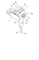
本発明に係るマイクロフォン装置は、図1に示す如く、2チャンネルの録音を行なうための2つのマイクロフォン(2a)(2b)と、これらのマイクロフォン(2a)(2b)を保持するためのマイクロフォンホルダー(1)とから構成されている。
マイクロフォンホルダー(1)は、例えばエラストマー樹脂等の比較的柔軟な合成樹脂から形成されたホルダー本体(15)にクリップ(3)を取り付けて構成され、該クリップ(3)を用いてマイクロフォンホルダー(1)を使用者の衣類に係止することが可能である。
Hereinafter, embodiments of the present invention will be specifically described with reference to the drawings.
As shown in FIG. 1, the microphone device according to the present invention includes two microphones (2a) (2b) for recording two channels and a microphone holder (2) for holding these microphones (2a) (2b). 1).
The microphone holder (1) is configured by attaching a clip (3) to a holder main body (15) formed of a relatively flexible synthetic resin such as an elastomer resin, and the microphone holder (1) is used by using the clip (3). ) Can be locked to the user's clothing.
マイクロフォン(2)は、図2に示す如く、前面カバー(23)よって前面が覆われたケーシング(22)を具え、該ケーシング(22)内の空間(29)に音響−電気変換器(21)が収容されている。ケーシング(22)には円筒壁部(27)が下向きに突設され、音響−電気変換器(21)から伸びるコード(20)が該円筒壁部(27)の内部を貫通して伸びている。又、ケーシング(22)には、前面カバー(23)の外周部を覆って耳パッド(25)が取り付けられている。 As shown in FIG. 2, the microphone (2) includes a casing (22) whose front surface is covered by a front cover (23), and an acoustic-electric converter (21) is placed in a space (29) in the casing (22). Is housed. The casing (22) has a cylindrical wall portion (27) protruding downward, and a cord (20) extending from the acoustic-electric converter (21) extends through the inside of the cylindrical wall portion (27). . The ear pad (25) is attached to the casing (22) so as to cover the outer periphery of the front cover (23).
前面カバー(23)には複数の前面貫通孔(24)が開設されて、第1の受音部を形成する一方、ケーシング(22)の背面壁部(26)及び円筒壁部(27)には、前面貫通孔(24)とは反対方向に開口する複数の背面貫通孔(28)が開設されて、第2の受音部を形成している。前面貫通孔(24)と背面貫通孔(28)は空間(29)に連通しており、背面貫通孔(28)から空間(29)を経て前面貫通孔(24)への音響の通過が可能である。 A plurality of front through holes (24) are formed in the front cover (23) to form the first sound receiving portion, while the rear wall portion (26) and the cylindrical wall portion (27) of the casing (22) are formed. Are provided with a plurality of back surface through holes (28) that open in the direction opposite to the front surface through holes (24) to form a second sound receiving portion. The front through hole (24) and the back through hole (28) communicate with the space (29), and sound can pass from the back through hole (28) through the space (29) to the front through hole (24). It is.
マイクロフォン(2)の前方側から伝わってくる音響は、前面カバー(23)の前面貫通孔(24)を通過し、音響−電気変換器(21)によって電気信号に変換される。又、マイクロフォン(2)の後方側から伝わってくる音響は、背面壁部(26)の背面貫通孔(28)を通過し、音響−電気変換器(21)によって電気信号に変換される。 Sound transmitted from the front side of the microphone (2) passes through the front through hole (24) of the front cover (23) and is converted into an electric signal by the sound-electric converter (21). The sound transmitted from the rear side of the microphone (2) passes through the back through hole (28) of the back wall (26) and is converted into an electric signal by the sound-electric converter (21).
上記マイクロフォン(2)は、前面カバー(23)側から耳道入口に挿入して耳に装着することが可能であり、この状態で前面貫通孔(24)は耳道奥部に通じると共に、背面貫通孔(28)は耳の外部空間へ通じることになる。 The microphone (2) can be inserted into the ear canal entrance from the front cover (23) side and attached to the ear. In this state, the front through-hole (24) leads to the back of the ear canal and the back surface. The through hole (28) leads to the external space of the ear.
マイクロフォンホルダー(1)のホルダー本体(15)は、図3及び図4に示す如く、中央部の仕切り壁(13)と、該仕切り壁(13)の左右に反対向きに突設された一対の第1筒壁部(11)(11)と、各第1筒壁部(11)から下方へ向けて突設された一対の第2筒壁部(12)(12)と、両第1筒壁部(11)(11)の側部に突設された凸部(14)とから構成され、両第1筒壁部(11)(11)と仕切り壁(13)とによって、互いに反対側を向いた左右一対のマイクロフォン係合凹部(10)(10)が形成されている。 As shown in FIGS. 3 and 4, the holder body (15) of the microphone holder (1) has a partition wall (13) at the center and a pair of protrusions projecting in opposite directions on the left and right of the partition wall (13). First cylinder wall portions (11) (11), a pair of second cylinder wall portions (12) (12) projecting downward from each first cylinder wall portion (11), and both first cylinders Consists of convex portions (14) projecting from the side portions of the wall portions (11) and (11), and the first cylindrical wall portions (11) (11) and the partition wall (13) are opposite to each other A pair of left and right microphone engaging recesses (10), (10) facing toward is formed.
図5に示す如く、マイクロフォンホルダー(1)の左右一対のマイクロフォン係合凹部(10)(10)には、左右一対のマイクロフォン(2a)(2b)をそれぞれ、背面壁部(26)側から挿入して着脱可能に係合させると共に、両マイクロフォン(2a)(2b)から伸びるコード(20)(20)の基端部をそれぞれ、マイクロフォンホルダー(1)の第2筒壁部(12)に着脱可能に係合させることが出来る。 As shown in FIG. 5, the pair of left and right microphones (2a) and (2b) are respectively inserted into the pair of left and right microphone engaging recesses (10) and (10) of the microphone holder (1) from the back wall (26) side. The base ends of the cords (20) and (20) extending from both microphones (2a) and (2b) are respectively attached to and detached from the second tube wall (12) of the microphone holder (1). Can be engaged.
この状態で、左右一対のマイクロフォン(2a)(2b)は、それぞれの前面貫通孔(24)がマイクロフォンホルダー(1)の両側部から外向きに開口し、両側から伝わってくる音響を音響−電気変換器(21)(21)によって電気信号に変換する。 In this state, the pair of left and right microphones (2a) and (2b) has a front through hole (24) that opens outward from both sides of the microphone holder (1), and the sound transmitted from both sides is acousto-electric. It converts into an electric signal by the converter (21) (21).
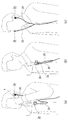
上記本発明のマイクロフォン装置において、電話機による通話内容の録音を行なう場合には、図6(a)の如く、マイクロフォンホルダー(1)から一方のマイクロフォン(2a)を取り外し、該マイクロフォン(2a)を耳に装着する。他方のマイクロフォン(2b)はマイクロフォンホルダー(1)に保持したままで、該マイクロフォンホルダー(1)を前記クリップ(3)によって使用者の衣服に係止する。この状態で、両マイクロフォン(2a)(2b)から伸びるコード(20)(20)をICレコーダ等のステレオ録音装置(図示省略)に接続する。そして、マイクロフォン(2a)を装着した耳に電話機(4)の受話部を押し付けて、通話を行なう。
In the above microphone device of the present invention, when recording the contents of a call using a telephone, one microphone (2a) is removed from the microphone holder (1) as shown in FIG. 6 (a), and the microphone (2a) is listened to. Attach to. The other microphone (2b) is held by the microphone holder (1), and the microphone holder (1) is locked to the user's clothes by the clip (3). In this state, the
ここで、耳に装着されたマイクロフォン(2a)は、背面貫通孔(28)が耳の外側に向き、前面貫通孔(24)が耳の内側に向いているので、電話機(4)の受話部から発せられる相手の声は、背面貫通孔(28)を通過して、音響−電気変換器(21)に至り、該マイクロフォン(2a)によって録音される。一方、使用者自身の声は、クリップ(3)によって使用者の衣服に取り付けられているマイクロフォン(2b)によって録音されることになる。尚、電話機(4)の受話部から発せられる相手の声は、マイクロフォン(2a)の背面貫通孔(28)から空間(29)を経て前面貫通孔(24)を通過し、使用者の耳の内部へ伝わるので、相手の声は明瞭に聞き取ることが出来る。 Here, the microphone (2a) attached to the ear has the back through hole (28) facing the outside of the ear and the front through hole (24) facing the inside of the ear. The voice of the other party emitted from the sound passes through the back through hole (28), reaches the acoustic-electric converter (21), and is recorded by the microphone (2a). On the other hand, the user's own voice is recorded by the microphone (2b) attached to the user's clothes by the clip (3). The other party's voice uttered from the receiver of the telephone (4) passes through the front through hole (24) from the rear through hole (28) of the microphone (2a) through the space (29), and passes through the front through hole (24). Because it is transmitted to the inside, the other party's voice can be heard clearly.
ステレオ録音を行なう場合には、図6(b)の如く、マイクロフォンホルダー(1)に両マイクロフォン(2a)(2b)を装着し、前記クリップ(3)によりマイクロフォンホルダー(1)を使用者の衣服に係止した状態で、両マイクロフォン(2a)(2b)から伸びるコード(20)(20)をICレコーダ等のステレオ録音装置(図示省略)に接続する。
両マイクロフォン(2a)(2b)がマイクロフォンホルダー(1)に保持された状態で、これらのマイクロフォン(2a)(2b)の前面貫通孔(24)は、ホルダー本体(15)の外側に向き、且つ互いに逆方向に向くので、使用者の左右から送られてくる音響を受音することになる。
When performing stereo recording, as shown in FIG. 6 (b), both microphones (2a) and (2b) are attached to the microphone holder (1), and the microphone holder (1) is attached to the user's clothes by the clip (3). The
With both microphones (2a) and (2b) being held by the microphone holder (1), the front through holes (24) of these microphones (2a) and (2b) are directed to the outside of the holder body (15), and Since they are directed in opposite directions, sound received from the left and right of the user is received.
ここで、マイクロフォンホルダー(1)に保持された両マイクロフォン(2a)(2b)は、マイクロフォンホルダー(1)の仕切り壁(13)によって互いに遮音されているので、左右の音響が混ざり合って録音されることはない。
この結果、両マイクロフォン(2a)(2b)によってステレオ録音を行なうことが出来る。
Here, since both microphones (2a) and (2b) held in the microphone holder (1) are sound-insulated by the partition wall (13) of the microphone holder (1), the left and right sounds are mixed and recorded. Never happen.
As a result, stereo recording can be performed using both
バイノーラル録音を行なう場合には、図6(c)に示す如く、マイクロフォンホルダー(1)から2つのマイクロフォン(2a)(2b)を取り外し、両マイクロフォン(2a)(2b)を両耳に装着する。この状態で、両マイクロフォン(2a)(2b)から伸びるコード(20)(20)をICレコーダ等のステレオ録音装置(図示省略)に接続する。
両耳に装着されたマイクロフォン(2a)(2b)は、それらの背面貫通孔(28)(28)が耳の外側に向いているので、使用者の周囲から使用者に向けて送られてくる音響は、両マイクロフォン(2)(2)の背面貫通孔(28)(28)を通過して音響−電気変換器(21)(21)に至る。これによって、バイノーラル録音が行なわれることになる。
When binaural recording is performed, as shown in FIG. 6C, the two
The microphones (2a) and (2b) attached to both ears are sent from the user's surroundings to the user because their back through holes (28) and (28) face the outside of the ear. The sound passes through the back through holes (28) and (28) of both microphones (2) and (2) and reaches the sound-electric converters (21) and (21). As a result, binaural recording is performed.
上述の如く、本発明に係るマイクロフォン装置によれば、電話機による通話内容の録音と、ステレオ録音と、バイノーラル録音の3つの録音方式を容易に実現することが可能である。 As described above, according to the microphone device of the present invention, it is possible to easily realize the three recording methods of recording the contents of a call by the telephone, stereo recording, and binaural recording.
尚、本発明の各部構成は上記実施の形態に限らず、特許請求の範囲に記載の技術的範囲内で種々の変形が可能である。例えばクリップ(3)に替えて、安全ピンによってマイクロフォンホルダー(1)を身体に係止する方法や、マイクロフォンホルダー(1)に首ベルトを取り付けてマイクロフォン装置を首からぶら下げる方法等を採用することが出来る。 In addition, each part structure of this invention is not restricted to the said embodiment, A various deformation | transformation is possible within the technical scope as described in a claim. For example, instead of the clip (3), a method of locking the microphone holder (1) to the body with a safety pin, a method of attaching a neck belt to the microphone holder (1), and hanging the microphone device from the neck may be adopted. I can do it.
又、マイクロフォンホルダー(1)に装着すべきマイクロフォン(2)の数は2つに限らず、3つ以上の複数のマイクロフォン(2)をマイクロフォンホルダー(1)に対してそれぞれ着脱可能に係合させた構成を採用することも可能である。これによって多チャンネルの録音が可能となる。 The number of microphones (2) to be attached to the microphone holder (1) is not limited to two, but three or more microphones (2) are detachably engaged with the microphone holder (1). It is also possible to adopt a different configuration. This enables multi-channel recording.
又、上記実施例では、マイクロフォン(2)をマイクロフォンホルダー(1)に装着した状態で、第1受音部が外向きに、第2受音部が内向きとなるようにしたが、第1受音部が内向きに、第2受音部が外向きとなるように装着する構成も採用可能である。これによって、ユーザは、マイクロフォン(2)の向きに注意を払うことなくマイクロフォンホルダー(1)への装着が可能となる。
更には、マイクロフォン(2)自体にホルダー機能を設け、複数のマイクロフォン(2)を互いに直接に連結してもよい。
In the above-described embodiment, the first sound receiving portion is directed outward and the second sound receiving portion is directed inward with the microphone (2) attached to the microphone holder (1). A configuration in which the sound receiving unit is mounted inward and the second sound receiving unit is mounted outward may be employed. Thus, the user can attach the microphone (1) to the microphone holder (1) without paying attention to the direction of the microphone (2).
Furthermore, the microphone (2) itself may be provided with a holder function, and the plurality of microphones (2) may be directly connected to each other.
(1) マイクロフォンホルダー
(10) マイクロフォン係合凹部
(11) 第1筒壁部
(12) 第2筒壁部
(13) 仕切り壁
(2) マイクロフォン
(20) コード
(21) 音響−電気変換器
(22) ケーシング
(23) 前面カバー
(24) 前面貫通孔
(26) 背面壁部
(28) 背面貫通孔
(29) 空間
(3) クリップ
(1) Microphone holder
(10) Microphone engagement recess
(11) First tube wall
(12) Second tube wall
(13) Partition wall
(2) Microphone
(20) Code
(21) Acoustic-electric converter
(22) Casing
(23) Front cover
(24) Front through hole
(26) Back wall
(28) Rear through hole
(29) Space
(3) Clip
Claims (9)
本体の外側へ向けると共にそれぞれの第2受音部をホルダー本体の内側へ向けて係合するマイクロフォン装置。 The microphone comprises a plurality of microphones for recording a plurality of channels and a microphone holder for holding these microphones. The microphone has a first sound receiving unit and a second sound receiving unit, and a second sound receiving unit. Sound can be passed from the first part to the first sound receiving part, and a plurality of microphone engaging recesses to which the plurality of microphones should be detachably engaged are arranged in different directions on the holder body of the microphone holder. These microphone engaging recesses are formed, and a plurality of microphones engage the respective first sound receiving portions toward the outside of the holder body and engage the respective second sound receiving portions toward the inside of the holder body. apparatus.
Priority Applications (3)
| Application Number | Priority Date | Filing Date | Title |
|---|---|---|---|
| JP2007225133A JP4889598B2 (en) | 2007-08-31 | 2007-08-31 | Microphone holder and microphone device using the same |
| US12/200,149 US8081789B2 (en) | 2007-08-31 | 2008-08-28 | Microphone holder and microphone device using same |
| CNA2008102151335A CN101378599A (en) | 2007-08-31 | 2008-09-01 | Microphone holder and microphone device using same |
Applications Claiming Priority (1)
| Application Number | Priority Date | Filing Date | Title |
|---|---|---|---|
| JP2007225133A JP4889598B2 (en) | 2007-08-31 | 2007-08-31 | Microphone holder and microphone device using the same |
Publications (3)
| Publication Number | Publication Date |
|---|---|
| JP2009060318A JP2009060318A (en) | 2009-03-19 |
| JP2009060318A5 JP2009060318A5 (en) | 2010-03-11 |
| JP4889598B2 true JP4889598B2 (en) | 2012-03-07 |
Family
ID=40407528
Family Applications (1)
| Application Number | Title | Priority Date | Filing Date |
|---|---|---|---|
| JP2007225133A Expired - Fee Related JP4889598B2 (en) | 2007-08-31 | 2007-08-31 | Microphone holder and microphone device using the same |
Country Status (3)
| Country | Link |
|---|---|
| US (1) | US8081789B2 (en) |
| JP (1) | JP4889598B2 (en) |
| CN (1) | CN101378599A (en) |
Families Citing this family (6)
| Publication number | Priority date | Publication date | Assignee | Title |
|---|---|---|---|---|
| US20090229083A1 (en) * | 2008-03-11 | 2009-09-17 | Plantronics, Inc. | Headset Clip System |
| CN101841751A (en) * | 2010-05-17 | 2010-09-22 | 苏州佳世达电通有限公司 | Speaker device |
| CN105100971A (en) * | 2014-05-09 | 2015-11-25 | 北京声望声电技术有限公司 | Mic fixing support and voice recording device |
| US9301037B1 (en) * | 2014-12-16 | 2016-03-29 | Clip & Talk Llc | Wireless phone accessory |
| WO2018006918A1 (en) * | 2016-07-05 | 2018-01-11 | Jan Juhler | Mount for miniature microphone |
| USD967076S1 (en) * | 2019-03-28 | 2022-10-18 | Sony Group Corporation | Microphone |
Family Cites Families (10)
| Publication number | Priority date | Publication date | Assignee | Title |
|---|---|---|---|---|
| GB1296882A (en) * | 1970-03-02 | 1972-11-22 | ||
| JP3031609B2 (en) * | 1994-11-30 | 2000-04-10 | 国際電気株式会社 | Small wireless communication device |
| JP2001048428A (en) * | 1999-08-05 | 2001-02-20 | Hosiden Corp | Cord storing device |
| WO2002039600A2 (en) * | 2000-11-07 | 2002-05-16 | Research In Motion Limited | Communication device with multiple detachable communication modules |
| US6316706B1 (en) * | 2000-11-10 | 2001-11-13 | Marvin L. Sammons | Multi-purpose entertainer stand |
| JP3905377B2 (en) * | 2001-12-27 | 2007-04-18 | 株式会社オーディオテクニカ | Microphone holder |
| US7436974B2 (en) * | 2004-07-06 | 2008-10-14 | Patrick Sean Harper | System and method for securing headphone transducers |
| US7877115B2 (en) * | 2005-01-24 | 2011-01-25 | Broadcom Corporation | Battery management in a modular earpiece microphone combination |
| JP4873936B2 (en) | 2005-11-15 | 2012-02-08 | 三洋電機株式会社 | Microphone device |
| EP2064815A4 (en) * | 2006-09-06 | 2009-11-11 | Newton Peripherals Llc | Wireless headset |
-
2007
- 2007-08-31 JP JP2007225133A patent/JP4889598B2/en not_active Expired - Fee Related
-
2008
- 2008-08-28 US US12/200,149 patent/US8081789B2/en not_active Expired - Fee Related
- 2008-09-01 CN CNA2008102151335A patent/CN101378599A/en active Pending
Also Published As
| Publication number | Publication date |
|---|---|
| US20090060247A1 (en) | 2009-03-05 |
| US8081789B2 (en) | 2011-12-20 |
| CN101378599A (en) | 2009-03-04 |
| JP2009060318A (en) | 2009-03-19 |
Similar Documents
| Publication | Publication Date | Title |
|---|---|---|
| JP4889598B2 (en) | Microphone holder and microphone device using the same | |
| US20050064915A1 (en) | Wireless headset for communications device | |
| US20110002498A1 (en) | In-ear headphone and headset | |
| JP2008193688A (en) | Headset | |
| KR20130110332A (en) | Soundproof housing and wire-wireless earset having the same | |
| WO2016036220A1 (en) | Earset | |
| CN115516872A (en) | Earphone communication system | |
| JP2007158924A (en) | Headphone unit | |
| CN211880590U (en) | Bone conduction earphone | |
| CN211880592U (en) | Earphone communication system | |
| CN211702356U (en) | Bone conduction earphone | |
| WO2016186344A1 (en) | Earset | |
| WO2019237647A1 (en) | Earphone capable of being flexibly worn | |
| US20230276156A1 (en) | Sound output device | |
| CN212628327U (en) | Bone conduction earphone | |
| KR20200111194A (en) | Hearing device | |
| TWM524643U (en) | Helmet with Bluetooth module | |
| CN212463474U (en) | Bone conduction earphone | |
| CN211880589U (en) | Bone conduction earphone | |
| CN211702355U (en) | Bone conduction earphone | |
| CN211702354U (en) | Bone conduction earphone | |
| CN115486093A (en) | Acoustic output device | |
| JP4873936B2 (en) | Microphone device | |
| JP2001333478A (en) | Speaker using helmet as component and helmet having speaker function | |
| CN210042156U (en) | Novel waterproof bone conduction bluetooth headset |
Legal Events
| Date | Code | Title | Description |
|---|---|---|---|
| A521 | Written amendment |
Free format text: JAPANESE INTERMEDIATE CODE: A523 Effective date: 20100126 |
|
| A621 | Written request for application examination |
Free format text: JAPANESE INTERMEDIATE CODE: A621 Effective date: 20100126 |
|
| RD03 | Notification of appointment of power of attorney |
Free format text: JAPANESE INTERMEDIATE CODE: A7423 Effective date: 20110328 |
|
| A977 | Report on retrieval |
Free format text: JAPANESE INTERMEDIATE CODE: A971007 Effective date: 20111109 |
|
| TRDD | Decision of grant or rejection written | ||
| A01 | Written decision to grant a patent or to grant a registration (utility model) |
Free format text: JAPANESE INTERMEDIATE CODE: A01 Effective date: 20111115 |
|
| A01 | Written decision to grant a patent or to grant a registration (utility model) |
Free format text: JAPANESE INTERMEDIATE CODE: A01 |
|
| A61 | First payment of annual fees (during grant procedure) |
Free format text: JAPANESE INTERMEDIATE CODE: A61 Effective date: 20111213 |
|
| FPAY | Renewal fee payment (event date is renewal date of database) |
Free format text: PAYMENT UNTIL: 20141222 Year of fee payment: 3 |
|
| S111 | Request for change of ownership or part of ownership |
Free format text: JAPANESE INTERMEDIATE CODE: R313113 |
|
| R350 | Written notification of registration of transfer |
Free format text: JAPANESE INTERMEDIATE CODE: R350 |
|
| LAPS | Cancellation because of no payment of annual fees |