JP4885200B2 - Gas turbine rotor blade having platform and method for forming the same - Google Patents
Gas turbine rotor blade having platform and method for forming the same Download PDFInfo
- Publication number
- JP4885200B2 JP4885200B2 JP2008305597A JP2008305597A JP4885200B2 JP 4885200 B2 JP4885200 B2 JP 4885200B2 JP 2008305597 A JP2008305597 A JP 2008305597A JP 2008305597 A JP2008305597 A JP 2008305597A JP 4885200 B2 JP4885200 B2 JP 4885200B2
- Authority
- JP
- Japan
- Prior art keywords
- platform
- blade
- gas turbine
- sealing plate
- shank
- Prior art date
- Legal status (The legal status is an assumption and is not a legal conclusion. Google has not performed a legal analysis and makes no representation as to the accuracy of the status listed.)
- Active
Links
Images


Classifications
-
- F—MECHANICAL ENGINEERING; LIGHTING; HEATING; WEAPONS; BLASTING
- F01—MACHINES OR ENGINES IN GENERAL; ENGINE PLANTS IN GENERAL; STEAM ENGINES
- F01D—NON-POSITIVE DISPLACEMENT MACHINES OR ENGINES, e.g. STEAM TURBINES
- F01D5/00—Blades; Blade-carrying members; Heating, heat-insulating, cooling or antivibration means on the blades or the members
- F01D5/12—Blades
- F01D5/14—Form or construction
- F01D5/18—Hollow blades, i.e. blades with cooling or heating channels or cavities; Heating, heat-insulating or cooling means on blades
- F01D5/187—Convection cooling
-
- F—MECHANICAL ENGINEERING; LIGHTING; HEATING; WEAPONS; BLASTING
- F05—INDEXING SCHEMES RELATING TO ENGINES OR PUMPS IN VARIOUS SUBCLASSES OF CLASSES F01-F04
- F05D—INDEXING SCHEME FOR ASPECTS RELATING TO NON-POSITIVE-DISPLACEMENT MACHINES OR ENGINES, GAS-TURBINES OR JET-PROPULSION PLANTS
- F05D2240/00—Components
- F05D2240/55—Seals
-
- F—MECHANICAL ENGINEERING; LIGHTING; HEATING; WEAPONS; BLASTING
- F05—INDEXING SCHEMES RELATING TO ENGINES OR PUMPS IN VARIOUS SUBCLASSES OF CLASSES F01-F04
- F05D—INDEXING SCHEME FOR ASPECTS RELATING TO NON-POSITIVE-DISPLACEMENT MACHINES OR ENGINES, GAS-TURBINES OR JET-PROPULSION PLANTS
- F05D2240/00—Components
- F05D2240/80—Platforms for stationary or moving blades
- F05D2240/81—Cooled platforms
-
- F—MECHANICAL ENGINEERING; LIGHTING; HEATING; WEAPONS; BLASTING
- F05—INDEXING SCHEMES RELATING TO ENGINES OR PUMPS IN VARIOUS SUBCLASSES OF CLASSES F01-F04
- F05D—INDEXING SCHEME FOR ASPECTS RELATING TO NON-POSITIVE-DISPLACEMENT MACHINES OR ENGINES, GAS-TURBINES OR JET-PROPULSION PLANTS
- F05D2260/00—Function
- F05D2260/20—Heat transfer, e.g. cooling
- F05D2260/221—Improvement of heat transfer
- F05D2260/2212—Improvement of heat transfer by creating turbulence
-
- F—MECHANICAL ENGINEERING; LIGHTING; HEATING; WEAPONS; BLASTING
- F05—INDEXING SCHEMES RELATING TO ENGINES OR PUMPS IN VARIOUS SUBCLASSES OF CLASSES F01-F04
- F05D—INDEXING SCHEME FOR ASPECTS RELATING TO NON-POSITIVE-DISPLACEMENT MACHINES OR ENGINES, GAS-TURBINES OR JET-PROPULSION PLANTS
- F05D2260/00—Function
- F05D2260/20—Heat transfer, e.g. cooling
- F05D2260/221—Improvement of heat transfer
- F05D2260/2214—Improvement of heat transfer by increasing the heat transfer surface
Description
本発明はプラットフォームを有するガスタービン動翼およびその形成方法、封止プレート、並びにそれらガスタービン動翼および封止プレートを有するガスタービンに関する。 The present invention relates to a gas turbine blade having a platform, a method for forming the same, a sealing plate, and a gas turbine having the gas turbine blade and the sealing plate.
図9は第1段動翼として主に使用されるガスタービン動翼101の代表的なプラットフォーム103の斜視図である。構造上、動翼は、翼102を形成するプロファイルと一体化したプラットフォーム、及び、プロファイル付根を有する。プラットフォームの下方には、クリスマスツリー形状の翼根151が形成され、図10に示すように、ロータディスク161の溝として同形状に形成された溝162に係合される。このような複数枚の動翼が、ロータディスクに設けられた溝に同じ方法で固定される。そして、同段のプラットフォームと動翼のシャンク104とにより形成される空洞(キャビティ)117がある。空洞は、ロータ側からのシール空気を供給するため、そしてこれにより、高温燃焼ガスがプラットフォーム間に存在する間隙を通じて高温燃焼ガスのガス通路から漏れるのを防ぐために設けられる。プラットフォームを冷却する手段の一つを、下記に記載している。従来技術による実施例において、特許文献1及び2に示すような、ガスタービン動翼のプラットフォーム103を、図11に示す。図11の(a)はプラットフォーム103の平面図であり、図11の(b)は(a)のA−A部断面図である。参照符号117はプラットフォーム103の内部空洞を提供し、この空洞はプラットフォームの一方の側に形成されている。参照符号123も空洞を提供し、この空洞はプラットフォーム103の他方の側に形成されている。参照符号122a、122b、122c及び122dは複数の冷却穴の一列をそれぞれ提供する。これらの冷却穴の列は、それぞれの空洞に個別に通じ、プラットフォーム103の一方の側の周辺に斜めにそれぞれ穿設される。これらの冷却穴の列は、上向き方向に空気の斜めの流れを得るように、そしてプラットフォームの表面を冷却するためのシール用空気として空気を拡散するように設けられている。この実施例において、シール空気は冷却するために使用されており、プラットフォーム103の下面の空洞117、123のそれぞれにおいて、インピンジ板171が空洞117,123を塞ぐように取付けられている。シール空気はインピンジ冷却を提供するように、インピンジ板171にある多数のインピンジ穴172から空洞中に冷却空気として導かれる。
FIG. 9 is a perspective view of a
プラットフォームの底にある空洞にシール空気を導き、そして空気が表面に設けられた冷却穴を経由して、空洞からさらにプラットフォームの表面に流れるのを可能にすることにより、プラットフォームの表面を冷却する一定の効果を作り出す。 Constant cooling of the platform surface by directing sealing air into the cavity at the bottom of the platform and allowing the air to flow from the cavity to the surface of the platform via cooling holes provided in the surface To produce the effect.
シール空気は主流の高温ガスが漏れるのを防ぐことを目的としており、普通は温度をコントロールしない。また、多量のシール空気が他の目的に使用されることは得策ではない。しかしながら、翼を冷却するために使用される空気は、シール空気とは無関係に、必要な場合には冷却された後に、翼に供給される。従ってシール空気に比べて、冷却空気は、それを冷却温度コントロールの目的に使用でき、その流量を調整できるという利点を有する。 Sealing air is intended to prevent the mainstream hot gas from leaking, and usually does not control the temperature. Also, it is not a good idea to use a large amount of sealing air for other purposes. However, the air used to cool the blades is supplied to the blades after being cooled if necessary, regardless of the sealing air. Therefore, compared with sealing air, cooling air has the advantage that it can be used for cooling temperature control purposes and its flow rate can be adjusted.
簡潔に言うと、本発明は、プラットフォームを有する動翼を冷却するのに適しており、かつシール空気だけで冷却するプラットフォーム冷却に依存しない方法及び手段を提供するためになされたものである。 Briefly, the present invention has been made to provide a method and means that are suitable for cooling a blade having a platform and that do not rely on platform cooling to cool only with sealed air.
前述のように、ガスタービンの動翼において、冷却空気は、それぞれの翼とプラットフォームとを冷却し、これにより高温燃焼ガスによるそれぞれのメタルの温度上昇を抑えるために提供される。ガスタービンの動翼において、プラットフォームと各翼のプロファイル部は質量に大きな差があるため、大きな温度差が両者の間に生じると、この温度差により大きな熱応力が発生する。プラットフォームと翼のプロファイル部との間に大きな熱応力が発生すると、クラックが発生しやすい。特にクラックが発生し易い部分は熱的に最も厳しい状況にさらされている部分、例えば、翼、及び、プラットフォームが据えられる後縁に位置するハブである。本発明は、特に、プラットフォームの熱応力、及び、燃損部分に焦点を合わせる。このような損傷は、長年の高温、高応力運転に基づくクリープ破壊と、各開始/停止運転で繰返し加えられた応力による金属疲労に基づく破壊との組合せにより引き起こされる。従って損傷を防ぐためには、応力が集中しやすい部分(即ち、翼の前縁及び後縁部のプラットフォーム付根部分)の温度及び(熱)応力をできるだけ下げることが必要である。 As described above, in the moving blades of the gas turbine, cooling air is provided to cool the respective blades and the platform, thereby suppressing the temperature rise of the respective metals due to the high-temperature combustion gas. In a moving blade of a gas turbine, since there is a large difference in mass between the platform and the profile portion of each blade, if a large temperature difference occurs between the two, a large thermal stress is generated due to this temperature difference. If a large thermal stress is generated between the platform and the profile portion of the blade, cracks are likely to occur. Particularly prone to cracking are the parts that are exposed to the most severe thermal conditions, such as the wings and the hub located at the trailing edge where the platform is placed. The present invention focuses specifically on the thermal stress and the burn-off portion of the platform. Such damage is caused by a combination of creep failure based on years of high temperature, high stress operation and failure based on metal fatigue due to stress repeatedly applied at each start / stop operation. Therefore, in order to prevent damage, it is necessary to reduce as much as possible the temperature and (thermal) stress of the portion where stress is likely to concentrate (that is, the platform root portion of the leading edge and the trailing edge of the blade).
そこで本発明は、熱応力の影響を特に受けやすい構造部分(即ち、翼内部の冷却通路から離れた部分の冷却構造)に改良を施し、熱応力によるクラックの発生及び熱損傷の発生を抑え、そしてプラットフォームの耐用年数を延ばすことにより、その信頼性を向上することができるガスタービン動翼およびその形成方法を提供することを目的としてなされたものである。
本発明の別の目的は、ガスタービン動翼キャビティ用封止プレートを提供することである。
本発明のさらに別の目的は、プラットフォームを有するガスタービン動翼を使用するガスタービンを提供することである。
Therefore, the present invention improves the structural part that is particularly susceptible to the influence of thermal stress (that is, the cooling structure in the part away from the cooling passage inside the blade) to suppress the generation of cracks and thermal damage due to thermal stress, The object of the present invention is to provide a gas turbine rotor blade and a method of forming the same that can improve the reliability of the platform by extending the service life of the platform.
Another object of the present invention is to provide a sealing plate for a gas turbine blade cavity.
Yet another object of the present invention is to provide a gas turbine that uses a gas turbine blade having a platform.
前述の課題を解決するため、本発明は次のとおりに具体化される。 In order to solve the above-described problems, the present invention is embodied as follows.
本発明の一つの実施形態において、プラットフォームを有するガスタービン動翼は、プラットフォームの周縁、プラットフォームの底面、及び、動翼のシャンクにより構成された凹部を有し、凹部はプラットフォームの周縁とシャンクとの間に封止プレートを配置することにより閉じられたキャビティで形成され、キャビティはシャンクの内部を通って冷却通路からキャビティまで空気を供給する供給路で形成され、冷却通路のそれぞれはガスタービン動翼の内部を空気冷却するために構成され、そしてキャビティは空気が前記キャビティから前記プラットフォームの表面に流れるのを各々可能にするための複数の冷却通路穴を設けられる。上記構造は熱応力によるクラック及び熱損傷を抑え、プラットフォームの耐用年数を延ばし、ガスタービン動翼の信頼性を向上させることに有効である。 In one embodiment of the present invention, a gas turbine blade having a platform has a recess comprised of a platform periphery, a platform bottom, and a blade shank, wherein the recess is between the platform periphery and the shank. Formed by closed cavities by placing a sealing plate in between, the cavities are formed by supply passages that supply air from the cooling passages to the cavities through the interior of the shank, each of the cooling passages being a gas turbine blade And the cavity is provided with a plurality of cooling passage holes to each allow air to flow from the cavity to the surface of the platform. The above structure is effective in suppressing cracks and thermal damage due to thermal stress, extending the service life of the platform, and improving the reliability of the gas turbine rotor blade.
封止プレートを、プラットフォームの周縁の下端に設けられた溝か、シャンクに設けられた溝のいずれかの、少なくとも一端に固定してもよい。これにより冷却に有効なキャビティが形成される。 You may fix a sealing plate to at least one end of either the groove | channel provided in the lower end of the periphery of a platform, or the groove | channel provided in the shank. Thereby, a cavity effective for cooling is formed.
プラットフォームの表面から、翼から離れる方向に放射状に空気が流れるように、冷却通路のそれぞれを穿孔してもよい。これによりプラットフォームの冷却がより有効になされる。 Each of the cooling passages may be perforated so that air flows radially away from the platform surface away from the wings. This makes the cooling of the platform more effective.
キャビティの縦断面において、断面部の幅を、プラットフォームの周縁に沿って狭くしてもよい。これにより冷却は最小限の冷却空気で行われる。 In the longitudinal section of the cavity, the width of the section may be narrowed along the periphery of the platform. Thereby, cooling is performed with a minimum amount of cooling air.
封止プレートを溝に挿入し、それから固定のために溶接又はロウ付けしてもよい。これはキャビティに封止プレートの取付けをする工程で容易かつ確実な好ましい効果をもたらす。 The sealing plate may be inserted into the groove and then welded or brazed for fixation. This provides an advantageous effect that is easy and reliable in the process of attaching the sealing plate to the cavity.
封止プレートをプラットフォームの周縁に向かって傾斜させてもよい。これにより冷却は最小限の冷却空気で行われる。 The sealing plate may be inclined toward the periphery of the platform. Thereby, cooling is performed with a minimum amount of cooling air.
ディンプル加工した板を封止プレートとして使用してもよい。これにより封止プレートへ強度を与え、熱伸びによる封止プレートの逃げを最小にする効果が生じる。 A dimple-processed plate may be used as the sealing plate. This gives strength to the sealing plate and produces the effect of minimizing escape of the sealing plate due to thermal elongation.
封止プレートは、細長い形状のディンプルを有してもよい。この配置は、構造上、封止プレートの強度及び熱伸びによる封止プレートの逃げなどを封止プレートの形状に適合させることができるという効果を有する。 The sealing plate may have an elongated dimple. This arrangement has an effect that the strength of the sealing plate and the escape of the sealing plate due to thermal elongation can be adapted to the shape of the sealing plate.
封止プレートは、お互いに独立した複数のディンプルを有する。これは、構造上、封止プレートの強度及び熱伸びによる封止プレートの逃げなどを封止プレートの形状に適合させることができるという効果を実現する。 The sealing plate has a plurality of dimples independent of each other. This realizes an effect that the strength of the sealing plate and the escape of the sealing plate due to thermal elongation can be adapted to the shape of the sealing plate.
封止プレートは、複数のプレートを横方向にお互いに接続することにより形成されたプレートである。これは、構造上、封止プレートの強度及び熱伸びによる封止プレートの逃げなどを封止プレートの形状に適合させることができるという効果を実現する。 The sealing plate is a plate formed by connecting a plurality of plates to each other in the lateral direction. This realizes an effect that the strength of the sealing plate and the escape of the sealing plate due to thermal elongation can be adapted to the shape of the sealing plate.
封止プレートは、湾曲形状のプレートである。これは、構造上、封止プレートの強度及び熱伸びによる封止プレートの逃げなどを封止プレートの形状に適合させることができるという効果を実現する。 The sealing plate is a curved plate. This realizes an effect that the strength of the sealing plate and the escape of the sealing plate due to thermal elongation can be adapted to the shape of the sealing plate.
本発明のもう一つの実施形態において、ガスタービン動翼キャビティのための封止プレートは、封止プレートの周辺部に複数の突起片を有する。封止プレートは複数の突起片のそれぞれに貫通穴を含んでもよい。封止プレートは穴が開いた複数の突起片のそれぞれの外側に切り欠きを含んでもよい。この配置はキャビティへの封止プレートの取付けを容易かつ確実にする。 In another embodiment of the present invention, the sealing plate for the gas turbine blade cavity has a plurality of protrusions on the periphery of the sealing plate. The sealing plate may include a through hole in each of the plurality of protruding pieces. The sealing plate may include a notch on the outer side of each of the plurality of protruding pieces with holes. This arrangement makes it easy and reliable to attach the sealing plate to the cavity.
本発明のもう一つの実施形態において、プラットフォームを有するガスタービン動翼を形成する方法は、プラットフォームの周縁、プラットフォームの底面、及び、動翼のシャンクを使用することにより凹部を形成すること、突起片を有する封止プレートの少なくとも一端を、プラットフォームの周縁の下端部か動翼のシャンク部のいずれかにあらかじめ設けられた溝に挿入すること、突起片のそれぞれを溝へ固定すること、及び、封止プレートの周縁を固定することを含む。このプラットフォーム形成方法は、作業性を向上させる。突起片のそれぞれに形成された切り欠きを、固定するために切り開いてそして外側に広げてもよい。この配置に基づいて、封止プレートを、容易かつ確実に取付けることができる。 In another embodiment of the present invention, a method of forming a gas turbine blade having a platform includes forming a recess by using a periphery of the platform, a bottom surface of the platform, and a shank of the blade, and a protruding piece. Inserting at least one end of a sealing plate having a groove into a groove provided in advance in either the lower end of the peripheral edge of the platform or the shank of the rotor blade, fixing each of the protruding pieces to the groove, and sealing Including fixing the periphery of the stop plate. This platform forming method improves workability. The notches formed in each of the protrusions may be cut open and spread outward to secure. Based on this arrangement, the sealing plate can be easily and reliably attached.
本発明のもう一つの実施形態において、プラットフォームを有するガスタービン動翼を使用するガスタービンは、プラットフォームの周縁、プラットフォームの底面、及び、動翼のシャンクにより構成された凹部を含み、凹部はプラットフォームの周縁とシャンクとの間に封止プレートを配置することにより閉じられたキャビティで形成され、キャビティはシャンクの内部を通って冷却通路からキャビティまで空気を供給する供給路で形成され、冷却通路のそれぞれはガスタービン動翼の内部を各々空気冷却し、そしてキャビティは複数の冷却通路穴を設けられ、空気がキャビティからプラットフォーム表面に流れるのを各々可能にする。 In another embodiment of the present invention, a gas turbine using a gas turbine blade having a platform includes a recess formed by a periphery of the platform, a bottom surface of the platform, and a shank of the blade. Formed by closed cavities by placing a sealing plate between the perimeter and the shank, the cavities being formed by supply channels that feed air from the cooling passages to the cavities through the interior of the shank, each of the cooling passages Each air cools the interior of the gas turbine blades and the cavities are provided with a plurality of cooling passage holes, each allowing air to flow from the cavities to the platform surface.
上記ガスタービン構造において、ガスタービン全体が冷却空気を有効に使用することができる。 In the gas turbine structure, the entire gas turbine can effectively use the cooling air.
本発明によるガスタービン動翼において、プラットフォームの周縁、プラットフォームの底面、及び、動翼のシャンクにより構成された凹部は、プラットフォームの熱応力により損傷しやすい部分に形成される。一方、封止プレートによって塞がれたキャビティは、プラットフォームの周縁とシャンクとの間に配置される。シャンクの内部を通ってキャビティに供給され、そしてキャビティから大変熱くなるプラットフォームの表面へ吹き出されて、動翼の内部を冷却する冷却空気により、他の部分について温度変化を引き起こすことなく損傷やクラックを防ぐことが可能である。上述した従来技術にあるようなシール空気を使用する場合に、シール空気の本来の目的を達成することは、多量の空気が冷却のために使用されるのを防ぐ。更に、従来技術と比べて、ガスタービン動翼の内部冷却通路から供給される冷却空気は十分な冷却性能を有し、従って冷却に対して大いに効果がある。 In the gas turbine rotor blade according to the present invention, the periphery of the platform, the bottom surface of the platform, and the recess formed by the shank of the rotor blade are formed in a portion that is easily damaged by the thermal stress of the platform. On the other hand, the cavity closed by the sealing plate is disposed between the periphery of the platform and the shank. Cooling air that is fed into the cavity through the interior of the shank and blown out of the cavity onto the surface of the platform, where it gets very hot, cools the interior of the blade, causing damage and cracking without causing temperature changes in other parts. It is possible to prevent. When using sealed air as in the prior art described above, achieving the original purpose of the sealed air prevents a large amount of air from being used for cooling. Furthermore, compared with the prior art, the cooling air supplied from the internal cooling passages of the gas turbine blades has sufficient cooling performance and is therefore very effective for cooling.
さらに、本発明においては、キャビティを形成する場合に、キャビティに隣接するプラットフォームの周縁とシャンクの両方の適当な部分に溝を設けたので、封止プレートを、溶接やロウ付けにより所定の位置に確実に固定することができる。 Furthermore, in the present invention, when forming the cavity, grooves are provided in appropriate portions of both the peripheral edge of the platform adjacent to the cavity and the shank, so that the sealing plate is put into a predetermined position by welding or brazing. It can be fixed securely.
本発明はもう一つの利点、先に述べた封止プレートの固定のより確実な方法、即ち、プレートに対する作業性がそれによって高められるような封止プレートの突起片の連結を有する。 The present invention has another advantage, a more reliable method of fixing the sealing plate as described above, i.e. the connection of the protrusions of the sealing plate such that the workability to the plate is enhanced.
本発明によるガスタービン動翼プラットフォームの実施例を、添付した図面に基づいて以下に詳細に説明する。 Embodiments of a gas turbine blade platform according to the present invention will be described in detail below with reference to the accompanying drawings.
図1の(a)は、本発明の実施例1による第1段ガスタービン動翼の縦断面図を示し、(b)は、(a)におけるA−A部の横断面図である。 FIG. 1A is a longitudinal sectional view of a first stage gas turbine rotor blade according to a first embodiment of the present invention, and FIG. 1B is a transverse sectional view taken along line AA in FIG.
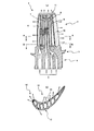
ガスタービン動翼1は、プロファイルを形成する翼2、翼2の付根部と接合しているプラットフォーム3、及び、プラットフォーム3の下に位置するシャンク4を含む。翼2の内部は、冷却空気が翼の下に配置されたロータ(図示せず)へ通じる翼根(ここでは図示していないクリスマスツリーのような形状)から冷却空気通路5へ最初に供給されるように構成されている。それから冷却空気は、翼内部を冷却するように、翼の内部に各々配置された前縁通路6及びサーペンタイン流路7、8へ供給される。冷却通路9において、冷却空気の一部は後縁10を冷却するために後縁10から吹き出され、そして冷却空気の残りは翼頂11からガス通路に吹き出される。また前縁通路6は、翼の前縁に位置する流出穴から冷却空気を流出させ、そして冷却空気の残りは翼頂11からガス通路に放出される。さらに(b)に示すように、翼の翼頭12、翼凸部13、及び、翼凹部14では、それらの表面が複数の流出穴15を有しており、それによっても冷却がもたらされる。
The
図2は、図1の(a)におけるB−B断面から見た場合のプラットフォーム3の一つの形態を示す。プラットフォーム3の下には、図2におけるC部の拡大断面図として図3において詳細に示されているように、周縁16が図3の下部に下端16aを有し、そしてキャビティ17が下端16aとシャンク4とによって形成されている。キャビティを閉じるための封止プレート18も取付けられている。このプレートを確実に保持するために、前述のシャンクと前述の周縁にはそれぞれ溝19aと19bが設けられており、プレート18が2つの溝の間に取付けられる。一方、プレートの周縁が溶接やロウ付けなどにより固定される。
FIG. 2 shows one form of the
キャビティ17への冷却通路20は、翼内部まで伸びる冷却通路5のいずれかから通じており、キャビティ内で特に熱が蓄積しやすく、そのため熱損傷を被りやすい部分21を冷却する。冷却通路20からの冷却空気は、複数の冷却通路22a、22b、22c及び22dを通り、それからプラットフォームの表面を冷却するためにプラットフォームから流出する。この場合において、一つの好ましい実施例は、冷却通路のそれぞれから放射状に流出する空気で形成されてもよい。冷却通路が側面に集中する代わりに周辺に分配されている場合に、冷却はより有効になる。
The
プラットフォームにおけるもう一つのキャビティ23は、封止プレートを備えておらず、シール空気を使用するように構成されている。またプラットフォームの周縁冷却通路24は、通路25に通じている。さらに他の冷却通路26及び27も設けられているが、これらの通路は本発明のプラットフォームにおけるキャビティの通路とは別に構成されている。即ち、キャビティ17は封止プレートにより塞がれているが、キャビティ23は封止プレートにより塞がれていない。
Another
図4は、本発明の実施例1におけるプラットフォ−ム3の底面から見た主要部の半截斜視図である。図4において、キャビティ17を塞ぐために取付けられた封止プレート18を有する構造が示されており、封止プレート18は4つの突起片18a、18b、18c及び18dを有する。しかしながら突起片の数は4つに限定されない。
FIG. 4 is a semi-perforated perspective view of the main part viewed from the bottom surface of the
図5は、図4におけるD−D部の横断面図であり、キャビティ17における封止プレート18の取付け状態を示している。封止プレート18は、溶接やロウ付けによって固定されるプレートの周辺と一体となっている突起片18a及び18bによって、シャンクの溝19aとプラットフォ−ムの周縁の溝19bとの間に挿入される。突起片18a及び18bが、溝19a及び19bに挿入されることにより溝19a及び19bに固定される前に、溝がシャンクに対して角度α(αは90度から135度までの適切な角度である)を取るように配置されれば、工具をシャンクから少し離れたところで容易に使用することができ、プレートを容易に取り付けることができるので、溶接やロウ付けなどに使用される工具での作業性は高められる。
FIG. 5 is a cross-sectional view taken along the line DD in FIG. 4 and shows a state in which the sealing
ガスタービン動翼のプラットフォーム表面は、燃焼ガスが通過する部分であるので、高温にさらされる。翼とプラットフォームの付根も高温にさらされ、温度も上昇するが、プラットフォームの表面が最も著しく熱くなる。プラットフォームの表面や、翼とプラットフォームの付根と比べると、プラットフォームの底面やシャンクは、大変低い温度状態に置かれている。そのために熱応力がプラットフォームに生じ、引張りを引き起こし、それ故にクラックを引き起こすかもしれない。従って、これらの要素の熱特性を超える温度に熱しないように、これらの要素を均一に冷却することが必要になる。この点を考慮して、本発明においては、キャビティがこの部分の冷却を向上させるために、プラットフォームの底面に形成される。 The platform surface of the gas turbine blade is exposed to high temperatures because it is the part through which the combustion gas passes. The roots of the wing and platform are also exposed to high temperatures and the temperature rises, but the surface of the platform is most heated. Compared to the surface of the platform and the base of the wing and the platform, the bottom surface and the shank of the platform are in a very low temperature state. This may cause thermal stresses on the platform, causing tension and hence cracking. It is therefore necessary to cool these elements uniformly so that they do not heat to a temperature that exceeds the thermal properties of these elements. In view of this point, in the present invention, a cavity is formed on the bottom surface of the platform in order to improve the cooling of this part.
図6は、もう一つの実施例による封止プレートの取付けの形態を示しており、プラットフォーム周端の下端16aとシャンク溝19aとの間に取付けられた湾曲した封止プレート18が示されている。この取付け形態は、大きなキャビティが形成されるべき場合に、またプラットフォームの下端に溝を容易につけることができない場合に、適している。
FIG. 6 shows a form of attachment of the sealing plate according to another embodiment, in which a
図7の(a)から(g)までは、様々な種類の封止プレートの平面及び側面形状を示す。(a)は一枚の平坦なプレートからなるフラット型を示し、(b)はプレートのほぼ全長に沿って伸びている細長いディンプル18−1を有するアーチ型のプレートを示す。(c)は中央に平坦な凹所を形成している弁当型のディンプル18−2を設けた封止プレートを示す。さらに(d)は略中央に独立した二つの細長いディンプル18−3及び18−4を有するへこみ型の封止プレートを示す。また(e)はプレートの表面と裏面の両方に細長いディンプル18−5又は18−6を有するへこみ組合せ型の封止プレートを示す。(f)は封止プレートの表面又は裏面に複数の独立した突起球状のディンプル18−7を有する封止プレートを示す。(g)は(a)の変形型として、溶接やロウ付けなどによりお互いに接合された数枚のプレート18−8及び18−9により構成された継ぎ型の封止プレートを示す。これらの種類のそれぞれは、封止プレートの熱伸びによる封止プレートの変形を防ぎ、例えプレートが薄くても十分な強度を持つことができる。 FIGS. 7A to 7G show the planar and side shapes of various types of sealing plates. (A) shows the flat type which consists of one flat plate, (b) shows the arch type plate which has the elongate dimple 18-1 extended along the substantially full length of the plate. (C) shows a sealing plate provided with a lunch box type dimple 18-2 having a flat recess in the center. Furthermore, (d) shows a dent-type sealing plate having two elongated dimples 18-3 and 18-4 which are independent at substantially the center. (E) shows a dent combination type sealing plate having elongated dimples 18-5 or 18-6 on both the front and back surfaces of the plate. (F) shows a sealing plate having a plurality of independent protruding spherical dimples 18-7 on the front or back surface of the sealing plate. (G) shows a joint type sealing plate constituted by several plates 18-8 and 18-9 joined to each other by welding, brazing or the like as a modified type of (a). Each of these types can prevent deformation of the sealing plate due to thermal elongation of the sealing plate, and can have sufficient strength even if the plate is thin.
図8の(a)から(c)までは、封止プレートの取付け工程を示す。(a)は、4つの周辺部に突起片18a、18b、18c及び18dを有するフラットプレート18の平面図である。4つの突起片の代表的な一つとして18bを参照すると、穴が突起片の略中央に設けられており、そして切り欠き18b−1が突起片の先端に設けられている。次に、プラットフォームの下端にある溝19bに挿入される一端を持つ上述したプレート18の部分拡大図である(b)に示すように、プラットフォーム3の周縁16の一端が突起片18bに嵌合され、その後に、部分的な封止が周縁16と突起片18bの連結から与えられる。次に、(b)におけるC−C断面の部分拡大図である(c)に示すように、突起片の切り欠き18b−1の両端が、プレートを溝に完全に挿入するために広げられる。この後に、プレートの周辺が固定のために溶接又はロウ付けされる。
(A) to (c) of FIG. 8 show the process of attaching the sealing plate. (A) is a top view of the
本発明は図解されたような実施例に関して記述されている一方で、本発明はそれらによって限定されないが、特許請求の範囲に様々な構造上の変更を当然含んでもよい。 While the invention has been described with reference to illustrative embodiments, the invention is not so limited, but various structural changes may naturally be included in the claims.
本発明によるガスタービン動翼のプラットフォームは、冷却性能を向上させ、従って耐用年数性能を向上させ、その形成方法が作業性を高める産業上の利用に対して非常に有意義である。 The gas turbine blade platform according to the present invention is of great significance for industrial applications that improve the cooling performance and thus the service life performance, and the formation method of which enhances workability.
1、101 ガスタービン動翼
2、102 翼
3、103 プラットフォーム
4、104 シャンク
5 冷却空気通路
6 前縁通路
7、8 サーペンタイン流路
9、20、22a、22b、22c、22d 24、26、27 冷却通路
10 後縁
11 翼頂
12 翼頭
13 翼凸部
14 翼凹部
15 流出穴
16 周縁
16a 下端
17、23 キャビティ
18 封止プレート
18a、18b、18c、18d 突起片
18−1、18−2、18−3、18−4、18−5、18−6、18−7 ディンプル
18b−1 切り欠き
18−8、18−9 プレート
19a、19b、162 溝
21 部分
25 通路
117、123 空洞
122a、122b、122c、122d 複数列の冷却穴の一列
151 翼根
161 ロータディスク
171 インピンジ板
172 インピンジ穴
α 角度
DESCRIPTION OF SYMBOLS 1,101 Gas turbine rotor blade 2,102 Blade 3,103 Platform 4,104
Claims (16)
前記プラットフォームの周縁、前記プラットフォームの底面、及び、前記動翼のシャンクにより構成された凹部を前記動翼の翼凹部側と前記動翼の翼凸部側とにそれぞれ備え、前記翼凹部側の前記凹部は、前記プラットフォームの周縁と前記シャンクとの間に封止プレートを配置することにより閉じられたキャビティで形成され、前記動翼の翼凸部側の前記凹部は、封止プレートにより塞がれておらず、
前記キャビティは、前記シャンクの内部を通って冷却通路から前記キャビティまで空気を供給する供給路で形成され、前記冷却通路のそれぞれは、前記ガスタービン動翼の内部を空気冷却するために構成され、
前記キャビティは、複数の冷却通路穴を設けられており、前記冷却通路穴のそれぞれは、前記冷却通路から供給された空気が前記キャビティから前記プラットフォームの表面に流れ、前記プラットフォームの表面をフィルム冷却するのを可能にするために構成され、そして、
前記動翼の翼凸部側の前記凹部は、ロータ側からのシール空気により冷却される構成であることを特徴とする、プラットフォームを有するガスタービン動翼。 In a gas turbine blade having a platform,
A peripheral edge of the platform, a bottom surface of the platform, and a concave portion formed by a shank of the moving blade are provided on a blade concave portion side of the moving blade and a blade convex portion side of the moving blade, respectively. The recess is formed by a cavity that is closed by disposing a sealing plate between the periphery of the platform and the shank, and the recess on the blade protrusion side of the moving blade is closed by the sealing plate. Not
The cavities are formed by supply passages that supply air from the cooling passages to the cavities through the interior of the shank, each of the cooling passages configured to air cool the interior of the gas turbine blades;
The cavity is provided with a plurality of cooling passage holes, and each of the cooling passage holes causes air supplied from the cooling passage to flow from the cavity to the surface of the platform to cool the surface of the platform. And is configured to enable
The gas turbine moving blade having a platform, wherein the concave portion on the blade convex portion side of the moving blade is cooled by seal air from the rotor side.
前記複数の突起片のそれぞれに貫通穴を設けられ、
前記貫通穴を設けた複数の突起片のそれぞれの外側に切り欠きを有し、
前記突起片を、前記プラットフォームの周縁の下端に設けられた溝か、前記シャンクに設けられた溝のいずれかの、少なくとも一端に挿入し、その外周が前記溝と対向している状態で、前記切り欠きを外側に開くことで、前記プラットフォームまたは前記シャンクに固定されることを特徴とする請求項1に記載の、プラットフォームを有するガスタービン動翼。 The sealing plate includes a plurality of protruding pieces on the periphery,
A through hole is provided in each of the plurality of protruding pieces,
Having a notch on the outside of each of the plurality of protruding pieces provided with the through hole,
The protruding piece is inserted into at least one end of either the groove provided at the lower end of the peripheral edge of the platform or the groove provided in the shank, and the outer periphery thereof is opposed to the groove, The gas turbine rotor blade having a platform according to claim 1, wherein the blade is fixed to the platform or the shank by opening a notch outward.
前記プラットフォームの周縁、前記プラットフォームの底面、及び、前記動翼のシャンクを使用して前記動翼の翼凹部側と前記動翼の翼凸部側とにそれぞれ凹部を形成すること、
突起片を有する封止プレートの少なくとも一端を、前記翼凹部側の前記プラットフォームの周縁の下端部か、前記動翼の翼凹部側の前記動翼のシャンク部のいずれかにあらかじめ設けられた溝に挿入すること、
前記突起片のそれぞれを前記溝へ固定すること、及び、
前記封止プレートの周縁を固定し、前記翼凹部側の前記凹部を前記封止プレートで閉じられたキャビティとし、前記キャビティで前記シャンクの内部を通って前記ガスタービン動翼の内部を空気冷却するための空気を流通させる冷却通路から前記キャビティまで空気を供給する供給路を形成し、前記キャビティに複数の冷却通路穴を設け、前記キャビティを前記冷却通路から供給された空気が前記冷却通路穴から前記プラットフォームの表面に流れ、前記プラットフォームの表面をフィルム冷却するのを可能にするとともに、前記動翼の翼凸部側の前記凹部は、前記封止プレートを設けずロータ側からのシール空気により冷却される構成とすることを含むことを特徴とする、プラットフォームを有するガスタービン動翼の形成方法。 In a method for forming a gas turbine rotor blade having a platform,
Using the peripheral edge of the platform, the bottom surface of the platform, and the shank of the moving blade to form recesses on the blade recessed portion side of the moving blade and the blade protruding portion side of the moving blade,
At least one end of the sealing plate having the projecting piece is provided in a groove provided in advance in either the lower end of the peripheral edge of the platform on the blade recess side or the shank portion of the rotor blade on the blade recess side of the blade. Inserting,
Fixing each of the protruding pieces to the groove; and
The periphery of the sealing plate is fixed, the recess on the blade recess side is a cavity closed by the sealing plate, and the inside of the gas turbine rotor blade is air-cooled by the cavity through the inside of the shank. Forming a supply passage for supplying air from the cooling passage for circulating air to the cavity, and providing a plurality of cooling passage holes in the cavity, and the air supplied from the cooling passage to the cavity is formed from the cooling passage hole. It flows on the surface of the platform and enables film cooling of the surface of the platform, and the concave portion on the blade convex portion side of the moving blade is cooled by sealing air from the rotor side without providing the sealing plate. A method of forming a gas turbine rotor blade having a platform, comprising:
前記プラットフォームの周縁、前記プラットフォームの底面、及び、前記動翼のシャンクにより構成された凹部を前記動翼の翼凹部側と前記動翼の翼凸部側とにそれぞれ備え、前記翼凹部側の前記凹部は、前記プラットフォームの周縁と前記シャンクとの間に封止プレートを配置することにより閉じられたキャビティで形成され、前記動翼の翼凸部側の前記凹部は、封止プレートにより塞がれておらず、
前記キャビティは、前記シャンクの内部を通って冷却通路から前記キャビティまで空気を供給する供給路で形成され、前記冷却通路のそれぞれは、前記ガスタービン動翼の内部を空気冷却するために構成され、そして、
前記キャビティは、複数の冷却通路穴を設けられており、前記冷却通路穴のそれぞれは、前記冷却通路から供給された空気が前記キャビティから前記プラットフォームの表面に流れ、前記プラットフォームの表面をフィルム冷却するのを可能にするために構成され、そして、
前記動翼の翼凸部側の前記凹部は、ロータ側からのシール空気により冷却される構成であることを特徴とする、ガスタービン。 In a gas turbine using a gas turbine blade having a platform,
A peripheral edge of the platform, a bottom surface of the platform, and a concave portion formed by a shank of the moving blade are provided on a blade concave portion side of the moving blade and a blade convex portion side of the moving blade, respectively. The recess is formed by a cavity that is closed by disposing a sealing plate between the periphery of the platform and the shank, and the recess on the blade protrusion side of the moving blade is closed by the sealing plate. Not
The cavities are formed by supply passages that supply air from the cooling passages to the cavities through the interior of the shank, each of the cooling passages configured to air cool the interior of the gas turbine blades; And
The cavity is provided with a plurality of cooling passage holes, and each of the cooling passage holes causes air supplied from the cooling passage to flow from the cavity to the surface of the platform to cool the surface of the platform. And is configured to enable
The gas turbine according to claim 1, wherein the concave portion on the blade convex portion side of the moving blade is cooled by seal air from the rotor side.
前記複数の突起片のそれぞれに貫通穴を設けられ、
前記貫通穴を設けた複数の突起片のそれぞれの外側に切り欠きを有し、
前記突起片を、前記プラットフォームの周縁の下端に設けられた溝か、前記シャンクに設けられた溝のいずれかの、少なくとも一端に挿入し、その外周が前記溝と対向している状態で、前記切り欠きを外側に開くことで、前記プラットフォームまたは前記シャンクに固定されることを特徴とする請求項15に記載の、ガスタービン。
The sealing plate includes a plurality of protruding pieces on the periphery,
A through hole is provided in each of the plurality of protruding pieces,
Having a notch on the outside of each of the plurality of protruding pieces provided with the through hole,
The protruding piece is inserted into at least one end of either the groove provided at the lower end of the peripheral edge of the platform or the groove provided in the shank, and the outer periphery thereof is opposed to the groove, The gas turbine according to claim 15, wherein the gas turbine is fixed to the platform or the shank by opening a notch to the outside.
Applications Claiming Priority (2)
| Application Number | Priority Date | Filing Date | Title |
|---|---|---|---|
| US11/138,449 US20060269409A1 (en) | 2005-05-27 | 2005-05-27 | Gas turbine moving blade having a platform, a method of forming the moving blade, a sealing plate, and a gas turbine having these elements |
| US11/138,449 | 2005-05-27 |
Related Parent Applications (1)
| Application Number | Title | Priority Date | Filing Date |
|---|---|---|---|
| JP2006031227A Division JP4302109B2 (en) | 2005-05-27 | 2006-02-08 | Gas turbine rotor blade having platform and method for forming the same |
Publications (2)
| Publication Number | Publication Date |
|---|---|
| JP2009047177A JP2009047177A (en) | 2009-03-05 |
| JP4885200B2 true JP4885200B2 (en) | 2012-02-29 |
Family
ID=37387825
Family Applications (2)
| Application Number | Title | Priority Date | Filing Date |
|---|---|---|---|
| JP2006031227A Active JP4302109B2 (en) | 2005-05-27 | 2006-02-08 | Gas turbine rotor blade having platform and method for forming the same |
| JP2008305597A Active JP4885200B2 (en) | 2005-05-27 | 2008-11-28 | Gas turbine rotor blade having platform and method for forming the same |
Family Applications Before (1)
| Application Number | Title | Priority Date | Filing Date |
|---|---|---|---|
| JP2006031227A Active JP4302109B2 (en) | 2005-05-27 | 2006-02-08 | Gas turbine rotor blade having platform and method for forming the same |
Country Status (4)
| Country | Link |
|---|---|
| US (1) | US20060269409A1 (en) |
| JP (2) | JP4302109B2 (en) |
| CN (1) | CN1869409A (en) |
| DE (1) | DE102006004437A1 (en) |
Families Citing this family (50)
| Publication number | Priority date | Publication date | Assignee | Title |
|---|---|---|---|---|
| US7416391B2 (en) * | 2006-02-24 | 2008-08-26 | General Electric Company | Bucket platform cooling circuit and method |
| US20100322767A1 (en) * | 2009-06-18 | 2010-12-23 | Nadvit Gregory M | Turbine Blade Having Platform Cooling Holes |
| US7695247B1 (en) * | 2006-09-01 | 2010-04-13 | Florida Turbine Technologies, Inc. | Turbine blade platform with near-wall cooling |
| JP2008145479A (en) | 2006-12-06 | 2008-06-26 | Konica Minolta Business Technologies Inc | Image forming apparatus |
| JP5281245B2 (en) * | 2007-02-21 | 2013-09-04 | 三菱重工業株式会社 | Gas turbine rotor platform cooling structure |
| EP2093381A1 (en) * | 2008-02-25 | 2009-08-26 | Siemens Aktiengesellschaft | Turbine blade or vane with cooled platform |
| CN101586477B (en) * | 2008-05-23 | 2011-04-13 | 中国科学院工程热物理研究所 | Turbulent baffle heat transfer enhancing device with jet impact function |
| US8096772B2 (en) * | 2009-03-20 | 2012-01-17 | Siemens Energy, Inc. | Turbine vane for a gas turbine engine having serpentine cooling channels within the inner endwall |
| US8529194B2 (en) * | 2010-05-19 | 2013-09-10 | General Electric Company | Shank cavity and cooling hole |
| US9416666B2 (en) | 2010-09-09 | 2016-08-16 | General Electric Company | Turbine blade platform cooling systems |
| US8840369B2 (en) * | 2010-09-30 | 2014-09-23 | General Electric Company | Apparatus and methods for cooling platform regions of turbine rotor blades |
| US8851846B2 (en) * | 2010-09-30 | 2014-10-07 | General Electric Company | Apparatus and methods for cooling platform regions of turbine rotor blades |
| US8777568B2 (en) | 2010-09-30 | 2014-07-15 | General Electric Company | Apparatus and methods for cooling platform regions of turbine rotor blades |
| US8814517B2 (en) | 2010-09-30 | 2014-08-26 | General Electric Company | Apparatus and methods for cooling platform regions of turbine rotor blades |
| US8794921B2 (en) * | 2010-09-30 | 2014-08-05 | General Electric Company | Apparatus and methods for cooling platform regions of turbine rotor blades |
| US8684664B2 (en) * | 2010-09-30 | 2014-04-01 | General Electric Company | Apparatus and methods for cooling platform regions of turbine rotor blades |
| US8814518B2 (en) * | 2010-10-29 | 2014-08-26 | General Electric Company | Apparatus and methods for cooling platform regions of turbine rotor blades |
| CH704252A1 (en) * | 2010-12-21 | 2012-06-29 | Alstom Technology Ltd | Built shovel arrangement for a gas turbine and method for operating such a blade arrangement. |
| US8628300B2 (en) * | 2010-12-30 | 2014-01-14 | General Electric Company | Apparatus and methods for cooling platform regions of turbine rotor blades |
| US8641368B1 (en) * | 2011-01-25 | 2014-02-04 | Florida Turbine Technologies, Inc. | Industrial turbine blade with platform cooling |
| US8641377B1 (en) * | 2011-02-23 | 2014-02-04 | Florida Turbine Technologies, Inc. | Industrial turbine blade with platform cooling |
| US8550783B2 (en) * | 2011-04-01 | 2013-10-08 | Alstom Technology Ltd. | Turbine blade platform undercut |
| US8651799B2 (en) * | 2011-06-02 | 2014-02-18 | General Electric Company | Turbine nozzle slashface cooling holes |
| US8858160B2 (en) | 2011-11-04 | 2014-10-14 | General Electric Company | Bucket assembly for turbine system |
| US8845289B2 (en) * | 2011-11-04 | 2014-09-30 | General Electric Company | Bucket assembly for turbine system |
| US9249673B2 (en) * | 2011-12-30 | 2016-02-02 | General Electric Company | Turbine rotor blade platform cooling |
| US9249674B2 (en) * | 2011-12-30 | 2016-02-02 | General Electric Company | Turbine rotor blade platform cooling |
| US10180067B2 (en) | 2012-05-31 | 2019-01-15 | United Technologies Corporation | Mate face cooling holes for gas turbine engine component |
| US9243501B2 (en) * | 2012-09-11 | 2016-01-26 | United Technologies Corporation | Turbine airfoil platform rail with gusset |
| EP2956627B1 (en) | 2013-02-15 | 2018-07-25 | United Technologies Corporation | Gas turbine engine component with combined mate face and platform cooling |
| US9810070B2 (en) * | 2013-05-15 | 2017-11-07 | General Electric Company | Turbine rotor blade for a turbine section of a gas turbine |
| CN103266310B (en) * | 2013-05-24 | 2015-05-20 | 上海和辉光电有限公司 | Dispersing plate and film coating device provided with same |
| EP3030751B8 (en) * | 2013-08-05 | 2021-04-07 | Raytheon Technologies Corporation | Gas turbine engine component and corresponding method of forming a gas turbine engine component |
| JP5606648B1 (en) * | 2014-06-27 | 2014-10-15 | 三菱日立パワーシステムズ株式会社 | Rotor blade and gas turbine provided with the same |
| US20160160652A1 (en) * | 2014-07-14 | 2016-06-09 | United Technologies Corporation | Cooled pocket in a turbine vane platform |
| US9982542B2 (en) * | 2014-07-21 | 2018-05-29 | United Technologies Corporation | Airfoil platform impingement cooling holes |
| CN106661946B (en) * | 2014-09-08 | 2018-05-22 | 西门子能源公司 | Include the cooling turbine guide vane platform of forepart, centre and blade trailing cooling chamber wherein |
| JP5905631B1 (en) * | 2015-09-15 | 2016-04-20 | 三菱日立パワーシステムズ株式会社 | Rotor blade, gas turbine provided with the same, and method of manufacturing rotor blade |
| US10280762B2 (en) * | 2015-11-19 | 2019-05-07 | United Technologies Corporation | Multi-chamber platform cooling structures |
| US10054055B2 (en) * | 2015-11-19 | 2018-08-21 | United Technology Corporation | Serpentine platform cooling structures |
| US10082033B2 (en) * | 2016-01-12 | 2018-09-25 | United Technologies Corporation | Gas turbine blade with platform cooling |
| US10260356B2 (en) * | 2016-06-02 | 2019-04-16 | General Electric Company | Nozzle cooling system for a gas turbine engine |
| EP3361056A1 (en) | 2017-02-10 | 2018-08-15 | Siemens Aktiengesellschaft | Guide blade for a flow engine |
| KR101873156B1 (en) * | 2017-04-12 | 2018-06-29 | 두산중공업 주식회사 | Turbine vane and gas turbine having the same |
| US10746033B2 (en) | 2017-08-02 | 2020-08-18 | Raytheon Technologies Corporation | Gas turbine engine component |
| US20190264569A1 (en) * | 2018-02-23 | 2019-08-29 | General Electric Company | Turbine rotor blade with exiting hole to deliver fluid to boundary layer film |
| JP7129277B2 (en) | 2018-08-24 | 2022-09-01 | 三菱重工業株式会社 | airfoil and gas turbine |
| US10882158B2 (en) | 2019-01-29 | 2021-01-05 | General Electric Company | Peening coated internal surfaces of turbomachine components |
| CN113404549A (en) * | 2021-07-26 | 2021-09-17 | 中国船舶重工集团公司第七0三研究所 | Turbine movable vane with root-extending air supply hole and edge plate air film hole |
| FR3127251A1 (en) * | 2021-09-23 | 2023-03-24 | Safran | Cooling of turbomachinery turbine blades |
Family Cites Families (22)
| Publication number | Priority date | Publication date | Assignee | Title |
|---|---|---|---|---|
| US4073599A (en) * | 1976-08-26 | 1978-02-14 | Westinghouse Electric Corporation | Hollow turbine blade tip closure |
| JPS56145858A (en) * | 1980-04-15 | 1981-11-12 | Unitika Ltd | Purifier for body fluid |
| JP2577937B2 (en) * | 1987-12-25 | 1997-02-05 | 松下電器産業株式会社 | Electronic device housing |
| JPH0211801A (en) * | 1988-06-29 | 1990-01-16 | Hitachi Ltd | Gas turbine cooling movable vane |
| JP2538412B2 (en) * | 1990-10-25 | 1996-09-25 | 三洋電機株式会社 | Lead frame and semiconductor device |
| US5382135A (en) * | 1992-11-24 | 1995-01-17 | United Technologies Corporation | Rotor blade with cooled integral platform |
| JP3399662B2 (en) * | 1994-10-20 | 2003-04-21 | 石川島播磨重工業株式会社 | Convection cooling structure |
| JP3040674B2 (en) * | 1994-11-16 | 2000-05-15 | 三菱重工業株式会社 | Gas turbine cooling blade |
| JP3411775B2 (en) * | 1997-03-10 | 2003-06-03 | 三菱重工業株式会社 | Gas turbine blade |
| JP2955252B2 (en) * | 1997-06-26 | 1999-10-04 | 三菱重工業株式会社 | Gas turbine blade tip shroud |
| JP3546135B2 (en) * | 1998-02-23 | 2004-07-21 | 三菱重工業株式会社 | Gas turbine blade platform |
| JP3510477B2 (en) * | 1998-04-02 | 2004-03-29 | 三菱重工業株式会社 | Gas turbine blade platform |
| JP3426952B2 (en) * | 1998-03-03 | 2003-07-14 | 三菱重工業株式会社 | Gas turbine blade platform |
| US6019572A (en) * | 1998-08-06 | 2000-02-01 | Siemens Westinghouse Power Corporation | Gas turbine row #1 steam cooled vane |
| EP1028228A1 (en) * | 1999-02-10 | 2000-08-16 | Siemens Aktiengesellschaft | Cooling device for a turbine rotor blade platform |
| FR2810365B1 (en) * | 2000-06-15 | 2002-10-11 | Snecma Moteurs | SYSTEM FOR VENTILATION OF A PAIR OF JUXTAPOSED DAWN PLATFORMS |
| US6341939B1 (en) * | 2000-07-31 | 2002-01-29 | General Electric Company | Tandem cooling turbine blade |
| US6402471B1 (en) * | 2000-11-03 | 2002-06-11 | General Electric Company | Turbine blade for gas turbine engine and method of cooling same |
| DE10059997B4 (en) * | 2000-12-02 | 2014-09-11 | Alstom Technology Ltd. | Coolable blade for a gas turbine component |
| US6478540B2 (en) * | 2000-12-19 | 2002-11-12 | General Electric Company | Bucket platform cooling scheme and related method |
| US7175391B2 (en) * | 2004-07-08 | 2007-02-13 | United Technologies Corporation | Turbine blade |
| US7131817B2 (en) * | 2004-07-30 | 2006-11-07 | General Electric Company | Method and apparatus for cooling gas turbine engine rotor blades |
-
2005
- 2005-05-27 US US11/138,449 patent/US20060269409A1/en not_active Abandoned
- 2005-11-29 CN CNA2005101269656A patent/CN1869409A/en active Pending
-
2006
- 2006-01-31 DE DE102006004437A patent/DE102006004437A1/en not_active Withdrawn
- 2006-02-08 JP JP2006031227A patent/JP4302109B2/en active Active
-
2008
- 2008-11-28 JP JP2008305597A patent/JP4885200B2/en active Active
Also Published As
| Publication number | Publication date |
|---|---|
| JP2009047177A (en) | 2009-03-05 |
| CN1869409A (en) | 2006-11-29 |
| DE102006004437A1 (en) | 2006-11-30 |
| JP4302109B2 (en) | 2009-07-22 |
| US20060269409A1 (en) | 2006-11-30 |
| JP2006329183A (en) | 2006-12-07 |
Similar Documents
| Publication | Publication Date | Title |
|---|---|---|
| JP4885200B2 (en) | Gas turbine rotor blade having platform and method for forming the same | |
| US7704045B1 (en) | Turbine blade with blade tip cooling notches | |
| US7303376B2 (en) | Turbine airfoil with outer wall cooling system and inner mid-chord hot gas receiving cavity | |
| US7309212B2 (en) | Gas turbine bucket with cooled platform leading edge and method of cooling platform leading edge | |
| EP1087102B1 (en) | Gas turbine bucket with impingement cooled platform | |
| US6602052B2 (en) | Airfoil tip squealer cooling construction | |
| JP2006083851A (en) | Cooling system for trailing edge of turbine bucket airfoil part | |
| EP2162598B1 (en) | Turbine airfoil cooling system with rotor impingement cooling | |
| EP1734228B1 (en) | Tip cap piece for a turbine bucket | |
| JP2006083850A (en) | Device and method for cooling turbine bucket platform | |
| EP2607624B1 (en) | Vane for a turbomachine | |
| JP6239163B2 (en) | Turbine blade cooling system with leading edge impingement cooling system and adjacent wall impingement system | |
| US20100135772A1 (en) | Turbine airfoil cooling system with platform cooling channels with diffusion slots | |
| EP1614860A2 (en) | Turbine blade | |
| US7708525B2 (en) | Industrial gas turbine blade assembly | |
| US10323520B2 (en) | Platform cooling arrangement in a turbine rotor blade | |
| JP2015521706A (en) | Turbine airfoil with cast platform cooling circuit | |
| US7905706B1 (en) | Turbine blade with spar and shell cooling | |
| US20070009349A1 (en) | Impingement box for gas turbine shroud | |
| JP5022097B2 (en) | Turbine blade | |
| US20110223036A1 (en) | Blade for a gas turbine | |
| KR20160056821A (en) | Cooling for turbine blade platform-aerofoil joints | |
| JP5047078B2 (en) | gas turbine | |
| JPS59160009A (en) | Stationary blade for gas turbine |
Legal Events
| Date | Code | Title | Description |
|---|---|---|---|
| A621 | Written request for application examination |
Free format text: JAPANESE INTERMEDIATE CODE: A621 Effective date: 20081128 |
|
| A131 | Notification of reasons for refusal |
Free format text: JAPANESE INTERMEDIATE CODE: A131 Effective date: 20101124 |
|
| A521 | Written amendment |
Free format text: JAPANESE INTERMEDIATE CODE: A523 Effective date: 20110124 |
|
| A131 | Notification of reasons for refusal |
Free format text: JAPANESE INTERMEDIATE CODE: A131 Effective date: 20110531 |
|
| A521 | Written amendment |
Free format text: JAPANESE INTERMEDIATE CODE: A523 Effective date: 20110714 |
|
| TRDD | Decision of grant or rejection written | ||
| A01 | Written decision to grant a patent or to grant a registration (utility model) |
Free format text: JAPANESE INTERMEDIATE CODE: A01 Effective date: 20111115 |
|
| A01 | Written decision to grant a patent or to grant a registration (utility model) |
Free format text: JAPANESE INTERMEDIATE CODE: A01 |
|
| A61 | First payment of annual fees (during grant procedure) |
Free format text: JAPANESE INTERMEDIATE CODE: A61 Effective date: 20111207 |
|
| FPAY | Renewal fee payment (event date is renewal date of database) |
Free format text: PAYMENT UNTIL: 20141216 Year of fee payment: 3 |
|
| R151 | Written notification of patent or utility model registration |
Ref document number: 4885200 Country of ref document: JP Free format text: JAPANESE INTERMEDIATE CODE: R151 |
|
| FPAY | Renewal fee payment (event date is renewal date of database) |
Free format text: PAYMENT UNTIL: 20141216 Year of fee payment: 3 |
|
| S111 | Request for change of ownership or part of ownership |
Free format text: JAPANESE INTERMEDIATE CODE: R313111 |
|
| R350 | Written notification of registration of transfer |
Free format text: JAPANESE INTERMEDIATE CODE: R350 |
|
| S533 | Written request for registration of change of name |
Free format text: JAPANESE INTERMEDIATE CODE: R313533 |
|
| R350 | Written notification of registration of transfer |
Free format text: JAPANESE INTERMEDIATE CODE: R350 |