JP4884591B2 - Code reader, entertainment system and recording medium - Google Patents
Code reader, entertainment system and recording medium Download PDFInfo
- Publication number
- JP4884591B2 JP4884591B2 JP2001062090A JP2001062090A JP4884591B2 JP 4884591 B2 JP4884591 B2 JP 4884591B2 JP 2001062090 A JP2001062090 A JP 2001062090A JP 2001062090 A JP2001062090 A JP 2001062090A JP 4884591 B2 JP4884591 B2 JP 4884591B2
- Authority
- JP
- Japan
- Prior art keywords
- code
- randomness
- imparting
- recording medium
- read
- Prior art date
- Legal status (The legal status is an assumption and is not a legal conclusion. Google has not performed a legal analysis and makes no representation as to the accuracy of the status listed.)
- Expired - Lifetime
Links
Images


Classifications
-
- G—PHYSICS
- G06—COMPUTING OR CALCULATING; COUNTING
- G06K—GRAPHICAL DATA READING; PRESENTATION OF DATA; RECORD CARRIERS; HANDLING RECORD CARRIERS
- G06K7/00—Methods or arrangements for sensing record carriers, e.g. for reading patterns
- G06K7/10—Methods or arrangements for sensing record carriers, e.g. for reading patterns by electromagnetic radiation, e.g. optical sensing; by corpuscular radiation
- G06K7/10544—Methods or arrangements for sensing record carriers, e.g. for reading patterns by electromagnetic radiation, e.g. optical sensing; by corpuscular radiation by scanning of the records by radiation in the optical part of the electromagnetic spectrum
-
- A—HUMAN NECESSITIES
- A63—SPORTS; GAMES; AMUSEMENTS
- A63F—CARD, BOARD, OR ROULETTE GAMES; INDOOR GAMES USING SMALL MOVING PLAYING BODIES; VIDEO GAMES; GAMES NOT OTHERWISE PROVIDED FOR
- A63F13/00—Video games, i.e. games using an electronically generated display having two or more dimensions
- A63F13/80—Special adaptations for executing a specific game genre or game mode
- A63F13/825—Fostering virtual characters
-
- A—HUMAN NECESSITIES
- A63—SPORTS; GAMES; AMUSEMENTS
- A63F—CARD, BOARD, OR ROULETTE GAMES; INDOOR GAMES USING SMALL MOVING PLAYING BODIES; VIDEO GAMES; GAMES NOT OTHERWISE PROVIDED FOR
- A63F13/00—Video games, i.e. games using an electronically generated display having two or more dimensions
- A63F13/90—Constructional details or arrangements of video game devices not provided for in groups A63F13/20 or A63F13/25, e.g. housing, wiring, connections or cabinets
- A63F13/92—Video game devices specially adapted to be hand-held while playing
Landscapes
- Physics & Mathematics (AREA)
- Engineering & Computer Science (AREA)
- Electromagnetism (AREA)
- General Physics & Mathematics (AREA)
- Toxicology (AREA)
- General Health & Medical Sciences (AREA)
- Artificial Intelligence (AREA)
- Computer Vision & Pattern Recognition (AREA)
- Health & Medical Sciences (AREA)
- Theoretical Computer Science (AREA)
- Optical Recording Or Reproduction (AREA)
- Record Information Processing For Printing (AREA)
- Control Or Security For Electrophotography (AREA)
- Accessory Devices And Overall Control Thereof (AREA)
- Signal Processing For Digital Recording And Reproducing (AREA)
- Credit Cards Or The Like (AREA)
Description
【0001】
【発明の属する技術分野】
本発明は、データを光学的に読み取り可能なコードとして記録した記録媒体からそのコードを光学的に読み取るコード読取装置、及び、そのような記録媒体、並びに、そのようなコード読取装置を用いた娯楽システムに関する。
【0002】
【従来の技術】
データを光学的に読み取り可能なコード、例えば一次元または二次元バーコートとして記録した記録媒体からそのコードを光学的に読み取るコード読取装置が各種知られている。
【0003】
【発明が解決しようとする課題】
上記のような従来のコード読取装置は、操作者によるコードの読み取り操作に対して、出力する情報が略一義的に決まっていたものであったため、これをゲーム機器等の娯楽システムや教育機器に応用した場合、単純な遊び方や機械的な学習方法しか提供できず、操作者に興趣を増したり、或いは興味を引き起こしたりするのにはどうしても一定の限界があった。
【0004】
本発明は、上記の点に鑑みてなされたものであり、本発明の一つの目的は、コード読取装置において、そのコードの読み取り結果にランダム性を付与するためのランダム性付与手段を具備することにより、操作者に対して、コードの読み取り操作に対する結果の意外性を簡単に提示できるようにし、もって、ゲーム機器等の娯楽システムや教育機器に好適に応用できるようにしたコード読取装置を提供することにある。
【0005】
また、本発明のもう一つの目的は、そのランダム性を活用し、遊びに豊富な変化を与えて操作者の楽しみを拡張する娯楽システムを提供することにある。
【0006】
【課題を解決するための手段】
上記の目的を達成するために、本発明によるコード読取装置は、データを光学的に読み取り可能なコードとして記録した記録媒体から上記コードを光学的に読み取るコード読取装置において、上記コードの読み取り結果にランダム性を付与するためのランダム性付与手段を具備することを特徴とする。
或いは、本発明によるコード読取装置は、データを光学的に読み取り可能なコードとして記録した記録媒体から前記コードを光学的に読み取るコード読取装置において、前記コードの読み取り結果にランダム性を付与するためのランダム性付与手段を具備し、前記ランダム性付与手段は、前記コードの読み取りに関するパラメータを検出することにより読み取り結果にランダム性を付与するパラメータ検出及びランダム性付与手段を含むことを特徴とする。
更に、本発明によるコード読取装置は、データを光学的に読み取り可能なコードとして記録した記録媒体から前記コードを光学的に読み取るコード読取装置において、前記コードの読み取り結果にランダム性を付与するためのランダム性付与手段を具備し、前記ランダム性付与手段は、前記記録媒体に関するパラメータを検出することにより読み取り結果にランダム性を付与する検出及び付与手段を含むことを特徴とする。
また、本発明によるコード読取装置は、データを光学的に読み取り可能なコードとして記録した記録媒体から前記コードを光学的に読み取るコード読取装置において、前記コードの読み取り結果にランダム性を付与するためのランダム性付与手段を具備し、前記ランダム性付与手段は、自己のコード読取装置固有のパラメータを検出することにより読み取り結果にランダム性を付与する検出及び付与手段を含むことを特徴とする。
或いは、本発明によるコード読取装置は、データを光学的に読み取り可能なコードとして記録した記録媒体から前記コードを光学的に読み取るコード読取装置において、前記コードの読み取り結果にランダム性を付与するためのランダム性付与手段を具備し、前記ランダム性付与手段は、前記コードを構成する所定の構成要素間の位置関係に関するパラメータを検出することにより読み取り結果にランダム性を付与する手段を含むことを特徴とする。
更に、本発明によるコード読取装置は、データを光学的に読み取り可能なコードとして記録した記録媒体から前記コードを光学的に読み取るコード読取装置において、前記コードの読み取り結果にランダム性を付与するためのランダム性付与手段を具備し、前記ランダム性付与手段は、前記コードを構成する所定の構成要素の輝度情報に関するパラメータを検出することにより読み取り結果にランダム性を付与する手段を含むことを特徴とする。
また、本発明によるコード読取装置は、データを光学的に読み取り可能なコードとして記録した記録媒体から前記コードを光学的に読み取るコード読取装置において、前記コードの読み取り結果にランダム性を付与するためのランダム性付与手段を具備し、前記ランダム性付与手段は、前記コードを構成する所定の構成要素の大きさに関するパラメータを検出することにより読み取り結果にランダム性を付与する手段を含むことを特徴とする。
或いは、本発明によるコード読取装置は、データを光学的に読み取り可能なコードとして記録した記録媒体から前記コードを光学的に読み取るコード読取装置において、前記コードの読み取り結果にランダム性を付与するためのランダム性付与手段を具備し、前記ランダム性付与手段は、前記コードを構成する所定の構成要素の形状に関するパラメータを検出することにより読み取り結果にランダム性を付与する手段を含むことを特徴とする。
更に、本発明によるコード読取装置は、データを光学的に読み取り可能なコードとして記録した記録媒体から前記コードを光学的に読み取るコード読取装置において、前記コードの読み取り結果にランダム性を付与するためのランダム性付与手段を具備し、前記ランダム性付与手段は、前記読み取られたコードから欠落した欠落情報に関するパラメータを検出することにより読み取り結果にランダム性を付与する手段を含むことを特徴とする。
【0007】
なお、上記コード読取装置を用いて娯楽システムを構成することができる。
【0008】
また、本発明による記録媒体は、ランダム性が付加されるべき情報とランダム性の付加に用いられる複数個の情報とを含むデータが、光学的に読み取り可能なコードとして記録され、上記コードがコード読取装置によって読み取られることにより、当該記録媒体から読み取られた上記複数個のランダム性の付加に用いられる情報から選択を行うことで、その読み取られたランダム性が付加されるべき情報の出力が変化されることを特徴とする。
【0009】
或いは、本発明による記録媒体は、ランダム性が付加されるべき情報と複数個の動きを選択可能なプログラムとを含むデータが、光学的に読み取り可能なコードとして記録され、上記コードがコード読取装置によって読み取られることにより、上記プログラムの動きが選択されて、その読み取られたランダム性が付加されるべき情報の出力が変化されることを特徴とする。
【0010】
更に、本発明による記録媒体は、ランダム性が付加されるべき情報とプログラムパラメータを取り扱うプログラムとを含むデータが、光学的に読み取り可能なコードとして記録され、上記コードがコード読取装置によって読み取られることにより、上記プログラムパラメータが変化され、それによってプログラムの動作が変化されるこで、その読み取られたランダム性が付加されるべき情報の出力が変化されることを特徴とする。
【0011】
即ち、本発明のコード読取装置、娯楽システム及び記録媒体によれば、コードの読み取り結果にランダム性を付与することができるので、操作者に対して、コードの読み取り操作に対する結果の意外性を簡単に提示できるようになる。
【0012】
【発明の実施の形態】
以下、本発明の実施の形態を図面を参照して詳細に説明する。
【0013】
[第1の実施の形態]
図1の(A)は、本発明の第1の実施の形態に係るコード読取装置の構成を示す図である。
【0014】
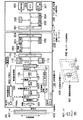
即ち、このコード読取装置は、読取装置本体100と、アプリケーションプログラム格納カートリッジ200と、プログラム処理装置300とから構成されている。上記読取装置本体100は、照明用LED101,結像レンズ102,撮像素子103,A/D変換回路104,2値化回路105,2値化メモリ106,CPU(マイコン)107,タイミング発生器108,照明駆動回路109,操作釦110,媒体センサ111,システムROM112,ワークRAM113,バスブリッジ114,及び電源部115からなる。また、上記アプリケーションプログラム格納カートリッジ200は、プログラムROM201,データRAM202,環境検出センサ203,及びコネクタ204を含んでいる。そして、上記プログラム処理装置300は、コネクタ301,CPU302,ROM303,RAM304,操作部305,液晶表示器(LCD)306,及び音声出力部307から構成されている。
【0015】
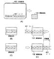
ここで、上記読取装置本体100内の照明用LED101は、記録媒体400上の、データが光学的に読み取り可能に記録されたコード401を照明するためのものであり、そのコード401からの反射光が上記結像レンズ102を介して上記撮像素子103によって撮像される。このとき、操作者が上記読取装置本体100又は上記記録媒体400を把持して当該読取装置本体100と記録媒体400とを相対的に移動させる、即ち手動走査することで、コード401がワンショットで撮像できないものであっても、そのコード全体を撮像することが可能である。勿論、コード401が、図1の(B)に示すように、ワンショットで撮像可能な場合には、そのような手動走査は不要である。更には、手動ではなく、記録媒体400を機械的に移動させるような自走式で撮像することも可能である。
【0016】
上記撮像素子103からのアナログ映像信号は、上記A/D変換回路104によって多値画像信号に変換され、更に、上記2値化回路105によって2値画像に変換されて、上記2値化メモリ106に記憶される。
【0017】
上記CPU107は、この2値化メモリ106に記憶された2値画像を処理して、上記コード401として記録された元のデータを復元する。また、このCPU107は、上記撮像素子103,A/D変換回路104,2値化回路105,及び2値化メモリ106に駆動信号を与える上記タイミング発生器108を制御することで、それら各部の駆動タイミングを制御する。更に、上記2値化回路105に閾値設定情報を与えることで2値化の閾値を制御し、上記照明駆動回路109に発光パルス信号を与えることで、上記照明用LED101の発光を制御する。
【0018】
なお、このCPU107による各部の制御動作は、上記操作釦110の操作に応じた操作指示情報により開始されることができる。或いは、上記媒体センサ111からの上記記録媒体400の検出信号により開始するようにしても良い。即ち、上記操作釦110と媒体センサ111とは択一的に設けても良いし、両方備えるようにしても構わない。
【0019】
上記システムROM112は、上記CPU107の動作プログラムや各種データを不揮発性に記憶しているメモリであり、上記ワークRAM113は、上記CPU107の動作中に各種データを一時記憶するのに用いられるメモリである。
【0020】
上記バスブリッジ114は、上記CPU107のシステムバスと上記アプリケーションプログラム格納カートリッジ200内のバスとを結合するためのものであり、これにより、上記CPU107から、上記復元したデータ等の各種データを上記アプリケーションプログラム格納カートリッジ200側へ通信できるようになっている。
【0021】
また、詳細は後述するが、上記CPU107は、上記A/D変換回路104からの多値画像情報より輝度情報等のパラメータを検出して、上記バスブリッジ114を介して上記アプリケーションプログラム格納カートリッジ200側へ送ったり、上記2値化メモリ106からの2値画像情報を処理して元のデータを復元する処理の途中で得られる各種パラメータを上記アプリケーションプログラム格納カートリッジ200側へ送ることも可能にされている。
【0022】
なお、上記電源部115は、該読取装置本体100内の各部へ電源を供給するためのものである。勿論、このような電源部115を設ける代わりに、該読取装置本体100内の各部への電源を、アプリケーションプログラム格納カートリッジ200を介してプログラム処理装置300側から供給するようにしても良い。
【0023】
一方、上記アプリケーションプログラム格納カートリッジ200の上記プログラムROM201は、上記プログラム処理装置300のCPU302で実行されるアプリケーションプログラムを不揮発性に記憶しているメモリである。
【0024】
また、上記データRAM202は、上記バスブリッジ114を介して上記CPU107から供給された上記復元されたデータや各種パラメータを保存するメモリである。
【0025】
そして、上記環境検出センサ203は、温度,湿度,時間,位置,気圧,等を検出するためのセンサである。なおこの場合、位置の検出は、GPSを利用したり、PHSの位置取得サービスを利用したりすることで行うことができる。
【0026】
上記コネクタ204は、上記プログラム処理装置300のコネクタ301と該アプリケーションプログラム格納カートリッジ200を電気的に接続するもので、例えば基板の端部に複数の接点を形成したエッジコネクタ等が用いられる。このコネクタ204と上記コネクタ301により、該アプリケーションプログラム格納カートリッジ200内のバスと上記プログラム処理装置300内のシステムバスとが結合され、上記プログラムROM201に記憶されたアプリケーションプログラム、データRAM202に保存されたデータやパラメータ、及び上記環境検出センサ203の検出値を、上記プログラム処理装置300のCPU302が読み出せるようになる。
【0027】
なお、特に図示はしていないが、該アプリケーションプログラム格納カートリッジ200内の各部への電源は、プログラム処理装置300側から供給されるようになっている。
【0028】
また、上記プログラム処理装置300の上記ROM303は上記CPU302の動作プログラムや各種データを不揮発性に記憶しているメモリであり、上記RAM304は、上記CPU302の動作中に各種データを一時記憶するのに用いられるメモリである。
【0029】
上記操作部305は、操作者が上記CPU302に対して所望の動作を指示するの用いられる釦等である。上記LCD306は、上記CPU302の制御によって画像表示データを表示出力するためのものであり、上記音声出力部307は、上記CPU302の制御によって音声データを音声出力するためのものである。
【0030】
なお、該プログラム処理装置300がビデオゲーム機の場合は、上記LCD306に代えて、テレビモニタ(図示せず)を接続するための端子(図示せず)と、上記CPU302の制御によって画像表示データを映像信号(ビデオ信号又はRGB信号)に変換する映像信号発生回路(図示せず)とが設けられることになる。
【0031】
而して、以上のような構成のコード読取装置では、プログラム処理装置300のCPU302がアプリケーションプログラム格納カートリッジ200のROM201に格納されたアプリケーションプログラムに従って、操作部305の操作に応じてLCD306の表示出力を変更したり、音声出力部307から音声出力を行う。そして、必要に応じて、記録媒体400に光学的に読み取り可能なコード401として記録されたデータが読取装置本体100によって読み取られ、その読み取り結果がアプリケーションプログラム格納カートリッジ200のRAM202に格納されるので、プログラム処理装置300のCPU302はそのコードの読み取り結果を読み出して、コードの読み取り結果に応じた表示出力又は音声出力を上記LCD306又は音声出力部307により行うものである。
【0032】
以上の動作は、従来のコード読取装置と同様であるが、本実施の形態に係るコード読取装置では、更に、読取装置本体100又はアプリケーションプログラム格納カートリッジ200で、上記コードの読み取りにおいて詳細は後述するようなパラメータを検出してRAM202に格納しておき、プログラム処理装置300のCPU302はそのパラメータに基づいて、上記コードの読み取り結果にランダム性を付与するものであり、それによって、操作者にコード401の読み取り操作に対する結果の意外性を提示できるようにしている。
【0033】
以下に、そのようなランダム性を付与するための手段と、ランダム性の内容について順に説明する。
【0034】
まず、ランダム性を付与するための手段について説明する。
【0035】
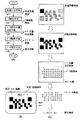
上記読取装置本体100の機能は、図2の(A)に示すように表すことができる。即ち、上記照明用LED101,結像レンズ102,撮像素子103,及びA/D変換回路104に対応する画像入力手段121によって、光学的に読み取り可能な上記コード401を撮像して、多値画像を得る。次に、上記2値化回路105,2値化メモリ106,及びCPU107に対応する2値化手段122により、上記多値画像を2値化して2値画像を得る。そして、上記CPU107に対応するデータ読取位置決定手段123により、上記2値画像におけるデータ読取点を決定すると共に、コード位置・形状情報を得る。その後、上記CPU107に対応するデータ読取手段124によって、上記2値画像から上記データ読取点の画像データを読み取ることで、コードデータを得る。そして、上記CPU107に対応するデータ復元手段125によって、上記コードデータに対し復号等の処理を行って、元のデータである復元情報を得る。
【0036】
例えば、記録媒体400に記録されたコード401が、図2の(B)に示すように、コード401であることを表すコード指標402と、記録されるべきデータの「1」又は「0」に応じて黒又は白の四角として示されるデータ403とからなるものであるとした場合、上記画像入力手段121で得られる多値画像情報,上記2値化手段122で得られる2値画像情報,上記データ読取位置決定手段123で得られるコード位置・形状情報,上記データ読取手段124で得られるコードデータ情報,及び上記データ復元手段125で得られる復元情報はそれぞれ、図2の(C)に示すようになる。
【0037】
これら、多値画像情報,2値画像情報,コード位置・形状情報,コードデータ情報,及び復元情報は、CPU107から上記バスブリッジ114を介して上記アプリケーションプログラム格納カートリッジ200のRAM202に格納され、プログラム処理装置300のCPU302によって読み出されて、その情報内容に応じて、上記復元情報であるコード401として記録されていたデータの出力にランダム性を付与することができる。
【0038】
ここで、上記多値画像情報からは、図3の(A)中の右上に示すように各画素の輝度を検出することで、最大輝度、最小輝度、又は平均輝度のパラメータを得ることができる。或いは、同図中の右下に示すように各輝度の発生頻度を検出することで、黒メジアン、白メジアン、又は極値のパラメータを得ることができる。更には、同図中の左下に示すような撮像領域内に所定領域を設けて、それぞれの平均輝度のパラメータを得ることもできる。勿論、そのような所定領域における最大輝度や黒メジアン等のパラメータを得ることも可能である。
【0039】
また、上記2値画像情報からは、図3の(B)中の右上に示すような黒画素と白画素の発生頻度のパラメータを得ることができる。或いは、同図中の右下に示すように、所定位置画素が黒画素であるのか白画素であるかという画素属性のパラメータを得ることができる。更には、同図中の左下に示すように、所定領域に黒画素と白画素が何パーセント存在するかという所定領域の画素分布のパラメータを得ることもできる。
【0040】
また、上記コード位置・形状情報からは、図4の(A)中の右上に示すようなコード構成要素の位置、大きさ、又は形状のパラメータを得ることができる。或いは、同図中の右下に示すようなデータの読取位置のパラメータを得ることができる。更には、同図中の左下に示すように、コード構成要素、例えばコード指標402、の検出数のパラメータを得ることもできる。
【0041】
また、上記コードデータ情報からは、図4の(B)に示すように、0の数や1の数、0と1の反転数、データ長、所定長毎の0と1の数、0の連続数や1の連続数、等々のパラメータを得ることができる。
【0042】
そして、上記復元情報からは、図4の(C)に示すように、情報の種類(それが絵なのか、文字なのか、音なのか、等)、情報の長さ(バイト数、時間、等)、情報の内容(作成者、コードや記録媒体のID、等)、等々のパラメータを得ることができる。
【0043】
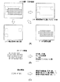
なお、コード401としては、図5の(A)に示すような二次元コードや同図の(B)に示すような一次元バーコードを利用することができる。
【0044】
ここで、図5の(A)に示すような二次元コードにおいては、コードの四隅のうち3つの角にコード指標402が配され、データ領域404中に、記録すべきデータに応じたデータセル403Aが記録されるようになっている。そして、データセル403Aの量が多い場合に、位置決めを精度良くするために、コード指標間402に位置決め指標405が配置されている。
【0045】
また、図5の(B)に示すような一次元バーコードは、コードの両脇にコード指標402が配され、それらの間に記録すべきデータ403に応じたバーが記録されて構成されるものである。
【0046】
更に、図5の(A)に示すようなコードにアドレス情報を加えてブロック化することで、図5の(C)に示すような複数のブロックからなるコードを構成することかできる。
【0047】
また、そのような複数ブロックからなるコードとしては、特開平8-171620号公報に開示されているようなドットコードが知られている。これは、図5の(D)に示すように、各ブロックが、記録すべきデータに対応したドットイメージが所定の2次元配列にて存在するブロックデータ404Aを有しており、更に、そのブロックデータ404A内の各ドット(データドット403B)を読み取るための読取基準点を見つけるために使用される各ブロックの四隅に配置された一定の黒の連続数を有するコード指標としてのマーカ402Aと、その読取基準点を更に精度良く見つけるために使用されるマーカ402A間に配置された孤立ドットの集合体である位置決め指標としてのパターンドット405Aと、各ブロックを識別するために同じくマーカ402A間に配置されたエラー検出又はエラー訂正符号を含むブロックアドレスパターン406と、を有しているものである。
【0048】
なお、上記2値化手段122は、図6の(A)に示すように、輝度情報検出手段122A、閾値制御手段122B、及び2値判定手段122Cから構成することができる。勿論、実際には、上記輝度情報検出手段122A及び上記閾値制御手段122Bは上記CPU107で、上記2値判定手段122Cは上記2値化回路105で構成されることになる。
【0049】
即ち、上記画像入力手段121からの多値画像情報の輝度を上記輝度情報検出手段122Aで検出し、上記閾値制御手段122Bは、この輝度情報を使用して、2値化の閾値を決定する(例えば、最大輝度と最小輝度の中間値を閾値とするなど)。そして、この決定された閾値の情報が上記閾値設定情報として、上記2値判定手段122Cとしての2値化回路105に与えられ、上記画像入力手段121からの多値画像情報を2値化することになる。
【0050】
このような構成によれば、上記輝度情報検出手段122Aからは、輝度情報が得られ、これにより、例えば前述したような輝度の最大値等のパラメータを抽出することが可能となる。また、上記閾値制御手段122Bからは、閾値情報が得られる。
【0051】
また、コード401として、図5の(A)や図5の(D)に示すような位置決め指標を有するコードを用いた場合には、上記データ読取位置決定手段123は、図6の(B)に示すように、コード指標検出手段123A、位置決め指標検出手段123B、データ読取位置算出手段123Cから構成されることができる。
【0052】
即ち、上記コード指標検出手段123Aにより、上記2値化手段122からの2値画像中よりコード指標402(マーカ402A)の画像を検出し、上記位置決め指標検出手段123Bにより、そのコード指標402間に配されている位置決め指標405(パターンドット405A)の画像を検出する。そして、上記データ読取位置算出手段123Cにより、そのコード指標及び位置決め指標の画像位置に基づいて2値画像中のデータ読取位置を算出する。
【0053】
このような構成によれば、上記コード指標検出手段123Aからは、コード指標の位置、数、形状情報が得られ、また、上記位置決め指標検出手段123Bからは、位置決め指標の位置、数、形状情報が得られることになる。
【0054】
また、コード401として、図5の(C)や図5の(D)に示したような複数のブロックからなるコードを用いた場合には、図6の(C)に示すように、アドレス検出手段126を更に含むことが必要となる。
【0055】
即ち、上記データ読取位置決定手段123で決定されたデータ読取位置のデータをデータ読取手段124で読み取るのと並行して、上記アドレス検出手段126により該データの含まれるブロックのアドレスを検出する。そして、上記データ復元手段125において、上記データ読取手段124で読み取ったデータを上記アドレス検出手段126で検出したアドレスに基づいて並び替えた上で、復元していくことになる。
【0056】
この場合には、上記アドレス検出手段126からは、アドレス情報を得ることが可能である。
【0057】
また、一般にコードデータには、変調をかけたり、エラー訂正データを付加することが行われる場合があるが、そのようなコードを用いた場合には、上記データ復元手段125は、図6の(D)に示すように、復調手段125A、エラー訂正情報抽出手段125B、及びエラー訂正手段125Cから構成される。
【0058】
即ち、例えば特開平6−231466号公報に開示されているように、データを光学的に読み取り可能なコード401として記録する際には一般に変調が施されているため、上記復調手段125Aによりその変調に対応する復調を上記データ読取手段124で読み取られたデータに対して行う。そして、上記エラー訂正情報抽出手段125Bにより、上記復調手段125Aで復調されたデータからエラー訂正情報を抽出し、上記エラー訂正手段125Cで、その抽出したエラー訂正情報に従って、上記復調手段125Aで復調されたデータのエラー訂正を行う。
【0059】
このような構成においては、上記復調手段125Aからは、復調後データ情報が得られ、また、上記エラー訂正情報抽出手段125Bからは、エラー訂正数や訂正位置などのエラー訂正情報が得られる。
【0060】
一方、コード401を手動走査する場合には、例えば図7の(A)に示すように、コード401はカード状の記録媒体400の一の辺に沿って記録され、このような記録媒体400を把持し、それを読取装置本体100に設けられたスリット131に沿って移動させることで、上記コード401の全体を上記スリット131の所定位置に位置決めされた撮像素子103の撮像領域132に入れていくことになる。
【0061】
或いは、図7の(B)に示すように、コード401はシート状の記録媒体400上に記録され、ペン型形状に形成され且つ上記アプリケーションプログラム格納カートリッジ200とケーブル500で接続された読取装置本体100を把持し、該読取装置本体100をコード401をなぞるように移動させることで、その先端に配された図示しない撮像領域にコード401の全体を入れていくことになる。
【0062】
そして、このようにコードを手動走査する場合には、更に、以下のような情報も取得できる。
【0063】
即ち、図8の(A)に示すように、コード401として図5の(C)や(D)に示すようなアドレス情報を持ちそのアドレスが順に並んでいるコードを使用して、撮像領域132に対して相対的に走査した場合には、相対的移動情報として速度のパラメータを求めることができる。これは、ある時点で図8の(B)に示すような撮像画面が得られ、次の撮像で同図の(C)に示すような撮像画面が得られたとすると、各撮像画面に含まれるアドレス情報より、同図の(D)に示すようにコードの移動量が求められる。そして、その移動量と撮像間隔(時間)とにより、コードの相対的移動速度を算出することができる。
【0064】
また、この算出された相対的移動速度を微分することで加速度のパラメータが求められる。
【0065】
或いは、図9の(A)に示すように、コード401として図5の(C)や(D)に示すようなアドレス情報を持ちそのアドレスが順に並んでいるコードを使用して、ペン型形状の読取装置本体100でコード401を走査した場合には、相対的移動情報として蛇行性に関するパラメータを求めることができる。これは、ある時点で図9の(B)に示すような撮像画面が得られ、次の撮像で同図の(C)に示すような撮像画面が得られたとすると、同図の(D)に示すように撮像領域132に対してコード401が移動していることが判る。従って、この場合には、同図の(E)に示すように、2つの撮像画面のアドレスを対応させることで、撮像画面間での移動量、つまりどれだけ蛇行したかが求められる。
【0066】
また、コード401として図5の(C)や(D)に示すようなアドレス情報を持ちそのアドレスが順に並んでいるコードを使用した場合には、相対的移動情報として、その相対移動の方向又は回数に関するパラメータを求めることも可能である。即ち、アドレスが昇順で検出されたのか、降順で検出されたのかにより、移動方向が判別できる。また、図7の(C)に示すように、「1,2,3,4,5,6,7,8,7,6,5,4,5,6,5,6,7,8,9,10,…」とアドレスが検出されたならば、そのアドレスの検出順により、同図中に丸数字で示す順にコード401が相対移動された、つまり移動方向と移動回数を共に求めることができる。
【0067】
また、以下のようにして、コード読取装置に関するパラメータも得ることができる。
【0068】
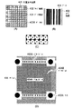
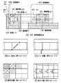
即ち、読取装置本体100が、図7の(A)に示したようなスリット131にカード状の記録媒体400を通すことでコード401を読み取るタイプの場合、照明用LED101,結像レンズ102,及び撮像素子103は、図10の(A)に示すように、記録媒体400がスリット131の底である走査ガイド133に当て付けながら移動されるときに、撮像領域132がコード401の位置となるように組み付けられる。
【0069】
このとき、図10の(B)に示すように、撮像画面より、例えばコード指標402の読取位置の情報等を利用して、コード401を構成するブロックの対角線長を検出することで、予めコード401のサイズが先見情報として与えられていれば、結像レンズ102の倍率に関するパラメータを求めることができる。
【0070】
或いは、図10の(C)に示すように、撮像画面の画面端からコード指標402までの距離を検出することで、走査ガイド133の位置に関するパラメータを求めることができる。
【0071】
また、図10の(D)に示すように、輝度情報(ここでは、所定領域毎の平均輝度の情報)を検出することで、照明用LED101の照明状態に関するパラメータを取得したり、図10の(E)に示すように、コードを構成するブロックの形状、例えばそれぞれの縦又は横方向長さを検出することで、結像レンズ102の歪み状態に関するパラメータを取得することができる。
【0072】
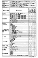
ここまでは、検出できるパラメータの種類やその検出方法について説明してきたが、図11は、ランダム性を出すために効果的なパラメータの例をまとめたものである。即ち、検出された情報と、その情報から得られるパラメータ、並びに、そのパラメータが「読取に関するパラメータ」、「読取方に関するパラメータ」、「記録媒体に関するパラメータ」、及び「読取装置に関するパラメータ」の何れとして特に有効であるかを一覧形式で示している。
【0073】
なお、「読取方に関するパラメータ」とは、同じ記録媒体で、操作者の操作の仕方により結果をコントロールできるような使い方が可能となるパラメータである。また、「記録媒体に関するパラメータ」とは、同じ読取装置で、同じように操作しても、読み取る媒体によって結果の出方がコントロールされるような使い方が可能となるパラメータである。そして、「読取装置に関するパラメータ」とは、同じ記録媒体で、同じように操作しても、読取装置によって結果の出方がコントロールされるような使い方が可能となるパラメータである。
【0074】
即ち、環境情報を検出すれば、温度、湿度、時間、位置、気圧、等々の読取環境パラメータが得られ、このパラメータは「読取に関するパラメータ」又は「読取装置に関するパラメータ」として利用して特に有効である。また、この環境情報としては、電源立ち上がり時間や電源電圧のパラメータを得ることも可能で、このパラメータは「読取装置に関するパラメータ」として利用して特に有効である。
【0075】
一方、多値画像情報を検出すれば、最大輝度、最小輝度、平均輝度、輝度分布、所定領域の平均輝度、等のパラメータが得られ、これらのパラメータは、例えばペン型形状の読取装置本体100の浮きや傾きのパラメータとなるので「読取方に関するパラメータ」として利用でき、また、例えば記録媒体400の反射率のパラメータでもあるので「記録媒体に関するパラメータ」として利用でき、或いは、照明用LED101の照明量やシェーディング、撮像素子103のセンサ感度のパラメータでもあるので「読取装置に関するパラメータ」として利用することができる。また、この多値画像情報からは、例えば最大輝度と最小輝度の比を演算することでコード401の記録濃度のパラメータを得ることができ、この濃度パラメータは「記録媒体に関するパラメータ」として利用できる。或いは、コード構成要素の輝度、例えばコード指標の輝度や背景の輝度のパラメータを得ることも可能で、このパラメータは「記録媒体に関するパラメータ」や「読取装置に関するパラメータ」として利用できる。
【0076】
また、閾値情報を検出すれば、閾値パラメータが得られ、これは、記録媒体の記録濃度や読取装置の照明量によって変化するので、「記録媒体に関するパラメータ」や「読取装置に関するパラメータ」として利用して特に有効である。
【0077】
一方、2値画像情報を検出すれば、黒画素数や白画素数、白/黒画素数比、等のパラメータが得られ、このパラメータはコードやその周辺のデザインに依存するので「記録媒体に関するパラメータ」として利用できる。また、特に黒画素数パラメータについては、照明量やシェーディング量にも関係するので、「読取装置に関するパラメータ」としても利用できる。
【0078】
更に、コード指標(位置決め指標)位置・数・形状情報を検出すれば、コード指標(位置決め指標)検出位置、コード指標(位置決め指標)検出数、コード指標大きさ、コード指標形状、コード指標重心/中心位置、コード指標間距離(コードやブロック大きさ)、コード指標位置関係(コードやブロック形状)、コード指標欠落情報、等のパラメータが得られる。これらのパラメータは「読取に関するパラメータ」及び「読取方に関するパラメータ」として利用して特に有効である。また、例えば印刷濃度や結像レンズ102の倍率で変化することから、コード指標検出位置、コード指標大きさ、コード指標形状、コード指標重心/中心位置、コード指標間距離、コード指標位置関係、及びコード指標欠落情報パラメータは、「記録媒体に関するパラメータ」及び「読取装置に関するパラメータ」として利用することができる。
【0079】
或いは、アドレス情報を検出すれば、アドレス、また、アドレスにエラー訂正符号を付加していればアドレスのエラー訂正数(アドレスデータ欠落)、アドレスエラー訂正位置、アドレス欠落情報、等のパラメータが得られる。ここで、アドレスパラメータは、例えばアドレス「10」が検出された/されない、或いは、アドレス「10」が何フレーム目で検出された(読み取り開始後、何mSで検出された)という情報であり、「読取に関するパラメータ」及び「読取方に関するパラメータ」として利用して特に有効である。また、アドレスエラー訂正数(アドレスデータ欠落)パラメータは、アドレスが幾つ誤ったかという情報であり、走査速度や蛇行、媒体上の汚れなどに依存するので「読取に関するパラメータ」、「読取方に関するパラメータ」、及び「記録媒体に関するパラメータ」として利用できる。また、アドレスエラー訂正位置パラメータは、アドレスのどこが誤ったかという情報であり、「記録媒体に関するパラメータ」として利用できる。更に、アドレス欠落情報パラメータは、読取方によってアドレスが欠落したり、記録状態によって欠落したり、或いは結像レンズ103が汚れていたり撮像素子103に欠損があることで欠落する等考えられるので、「読取に関するパラメータ」、「読取方に関するパラメータ」、「記録媒体に関するパラメータ」及び「読取装置に関するパラメータ」として利用して特に有効である。
【0080】
一方、コードデータ情報からは、データ読取位置、黒数、白数、黒/白比、データ長、ブロック読取数、等のパラメータが得られる。これらのパラメータは、どういうコードが記録されているかに起因するので、「記録媒体に関するパラメータ」として利用して特に有効である。また、データ読取位置パラメータについては、蛇行などに起因することもあるので、「読取に関するパラメータ」及び「読取方に関するパラメータ」としても利用できる。更に、ブロック読取数パラメータは、例えば走査速度が速すぎで全てのブロックを読み取れないというようなことがあるので、「読取に関するパラメータ」及び「読取方に関するパラメータ」としても利用できる。
【0081】
また、復調後データ情報を検出した場合には、1の数、0の数、1/0の比等のパラメータが得られ、これらのパラメータは、コードに起因するので、「記録媒体に関するパラメータ」として利用して特に有効である。
【0082】
一方、エラー訂正情報を検出した場合には、エラー訂正数(データ欠落)及びエラー訂正位置パラメータが得られる。ここで、エラー訂正数(データ欠落)パラメータは、走査速度や記録媒体の状態に依存するので、「読取に関するパラメータ」、「読取方に関するパラメータ」及び「記録媒体に関するパラメータ」として利用される。エラー訂正位置パラメータは、記録状態に依存するところが大きいので、「記録媒体に関するパラメータ」として利用して特に有効である。
【0083】
また、復元情報を検出した場合には、ID、作成者、情報の種類、記録時間、データ量、等のパラメータが得られ、これらのパラメータは、コードに記録されている情報に依存するので、「記録媒体に関するパラメータ」として利用して特に有効である。
【0084】
そして、相対的移動情報が検出された場合には、移動速度、移動方向、移動回数、等のパラメータが得られ、これらのパラメータは「読取に関するパラメータ」及び「読取方に関するパラメータ」として利用して特に有効である。また、蛇行性パラメータも得られるが、このパラメータは、ペン型形状の読取装置本体100を使用する場合には「読取に関するパラメータ」、「読取方に関するパラメータ」として利用され、また、スリット131にカード型の記録媒体400を通してコードを読み取るタイプの読取装置本体100が使用される場合には、記録媒体400の裁断辺の裁断誤差に起因するので「記録媒体に関するパラメータ」として、更には、裁断辺と接する走査ガイド133と撮像素子103との組み付け誤差等にも起因するので、「読取装置に関するパラメータ」としても利用できる。
【0085】
また、この相対的移動情報からは、上記操作釦110の操作又は媒体センサ111による媒体検出に応じた入力指示がなされた時点から実際にコードの所定位置を撮像するまでの時間をパラメータとして得ることができ、このパラメータは、「読取に関するパラメータ」及び「読取方に関するパラメータ」として利用することができる。
【0086】
なお、図11中に丸で示すのは、特に有効という意味であり、丸が付されていなくても、当該パラメータが「読取に関するパラメータ」、「読取方に関するパラメータ」、「記録媒体に関するパラメータ」、又は「読取装置に関するパラメータ」として利用できる場合もある。
【0087】
また、「読取方に関するパラメータ」としては、図12の(A)に示すようなマスキングカードを利用することも考えられる。
【0088】
即ち、マスキングカード400Mは、寸法形状同一のものが複数セット存在し、それぞれ上記カード型の記録媒体400に対応するデータカード400D上のデータコード401Dに対応する位置に孔411が設けられ、その孔411の横に制御コード401Cが配されている。ここで、制御コード401Cの大きさ及び印刷位置は同一であり、よって、操作者から見たマスキングカード400Mはどれも同じである。
【0089】
また、データカード400Dは、データコード401Dのコードブロック構成、印刷位置は同一であり、マスキングカード400Mによって選択される情報を含んだデータコード401Dを記録したデータカード400Dを複数種類制作するものである。
【0090】
そして、同図の(B)に示すように、欲しい情報カード(データカード400D)の上に、任意に選択したマスキングカード400Mを重ねて、コードの読取操作を行うと、制御コード412とデータコード401Dとが読み取られ、その制御コード412の情報に従って、データコード401Dから読み取られるブロックが決定される。
【0091】
即ち、同図の(C)に示すように、データコード401Dのみをコード読取装置で読み取った場合には、そのデータコード401DのZのブロックのみが読まれ、そのZには、例えば「マスキングカードを重ねて読んでね」というメッセージが表示出力又は音声出力されるようなデータが記録されている。そして、制御コード401Cとして制御コード“A”が記録されたマスキングカード400Mを重ねて読み取ると、データコード401DのAのブロックのみが読まれる。
【0092】
このように重ねるマスキングカードとデータコードの組み合わせにより、出力が異なってくるものである。
【0093】
次に、上記のようなランダム性を付与するための手段を用いて、コードの読取結果にどのようなランダム性を与えることができるかを説明する。
【0094】
ここでは、本実施の形態に係るデータ読取装置が娯楽システムであるものとして説明する。
【0095】
この場合、図13の(A)に示すように、上記プログラム処理装置300は携帯型のゲーム機本体として提供され、偏平に形状をしたハウジング311の一方主面(図示の表面)に上記操作部305及びLCD306を装着している。ハウジング311の背面上部には、ゲームカートリッジとして提供される上記アプリケーションプログラム格納カートリッジ200を挿入するための挿入孔312が形成されている。一方、ゲームカートリッジとしてのアプリケーションプログラム格納カートリッジ200は、上記挿入孔312に挿入される側と反対側に上記読取装置本体100が一体的に取り付けられている。この場合、該カートリッジ200がゲーム機本体としての上記プログラム処理装置300に装着されたときに上部となる位置に、上記記録媒体400が通されるスリット131が露出するように形成されている。
【0096】
一方、記録媒体400は、図1の(C)に示すような遊戯カードのセットとして提供される。即ち、この遊戯カードとしての記録媒体400は、その一方主面に、図柄表示領域431と、能力データ記録領域432と、データを光学的に読み取り可能に記録したコード401とが記録形成されたものである。
【0097】
ここで、上記図柄表示領域431は、例えば記録媒体400が縦長の長方形であれば、最も目立つ上部(上半分)領域又は上半分よりも多少広い領域の領域に形成され、その中に動物又は人物若しくは架空のモンスター等の種々のキャラクタが印刷等によって描かれる。また、この図柄表示領域431に描かれるキャラクタは、遊戯カードの特徴を表すために、カード毎に異なる種類又はデザイン若しくは図柄のキャラクタであり、ゲームカートリッジとしてのアプリケーションプログラム格納カートリッジ200のROM201に記憶されたゲームプログラムを実行したときにゲーム画面に登場するキャラクタ(主人公キャラクタ又は味方や敵のキャラクタ若しくは収集対象となるキャラクタ等)を含む。このキャラクタは、好ましくは収集家(コレクター)が収集したくなるような珍しいキャラクタや可愛らしいキャラクタが任意の確率で含まれるように、多数枚(例えば30枚〜40枚)組み合わせてセット販売(これを「スタータキット」という)されるか、読取装置本体100及びアプリケーションプログラム格納カートリッジ200と同梱してセット販売される。また、これらの多数枚のセット販売とは別に、少ない枚数で複数枚組み合わせてセット販売(これを「拡張パック」という)される場合もある。更に、読取装置本体100がアプリケーションプログラム格納カートリッジ200と別体として提供される時には、上記スタータキットをアプリケーションプログラム格納カートリッジ200と同梱してセット販売して良い。
【0098】
また、上記能力データ記録領域432は、上記図柄表示領域431に描かれたキャラクタの能力データ(属性データという場合もある)を文字,記号,数値若しくはこれらの組み合わせで表示する領域であり、例えば、キャラクタの名称とキャラクタ番号、キャラクタの使用できる武器又は魔法、体力,パワー,ヒットポイント,攻撃力,防禦力等を表す文字又は記号とその量を示す数値、その他種々のデータが目視可能(視覚的に認識可能)に印刷される。さらに、必要に応じて、この能力データ記録領域432には、キャラクタの描かれた記録媒体400の稀少価値の程度を表す記号(レア度マーク)が印刷される。
【0099】
上記コード401は、遊戯カードとしての記録媒体400の少なくとも一辺に沿って目立たないように形成される。このコード401は、必要に応じて、上記記録媒体400の上記図柄表示領域431及び能力データ記録領域432を除く領域であって、対向する二辺に沿って形成しても良く、また、上記図柄表示領域431及び能力データ記録領域432を囲む三辺又は四辺に沿って形成しても良い。このコード401として記録されるデータは、例えば、上記能力データ記録領域432に記録されているキャラクタの識別コード,ゲームに使用できる技又は武器,特徴を説明した単語又は文章等の文字(又はテキスト)データ等の能力データと同じデータであったり、それに追加するデータ(例えば、音声データ,キャラクタの図柄を示すドットデータ若しくはグラフィックデータ)等の複数の情報を含む。
【0100】
なおここで、上記能力データ及び追加データは、ゲーム内容に応じて適宜選択されるデータである。追加データは、キャラクタが人間であれば話し声,動物や架空のモンスターであれば鳴き声等の音声データ、目視可能な態様で記録されている能力データ以外の追加能力データ(魔法を使えるアイテムや一定時間無敵状態になる等の隠し能力データ)等が含まれる。
【0101】
例えば、ゲーム内容が架空のモンスターの捕獲又は育成ゲームの場合は、図柄表示領域431に描かれるキャラクタがモンスターであり、コード401として記録されるデータ(能力データ及び/又は追加データ)がモンスター毎の技のデータ,鳴き声の音声データ,進化に関するデータ,モンスターの特徴を説明する単語又は文章等の説明文(文字又はテキストデータ),これらの説明文の翻訳データ等である。また、ゲーム内容が野球又はサッカー等のスポーツゲームの場合は、キャラクタがスポーツ(野球又はサッカー)選手の写真であり、コード401として記録されるデータが写真の選手のチーム名,背番号,年令に加えて成績データ(野球の場合は、打者ならば打率,ホームラン数,打点,盗塁数,走力等、投手ならば防禦率,奪三振数,自責点等。サッカーの場合は、身体能力,得点,アシスト数等)である。また、ゲーム内容がロールプレイングゲーム又はアクションゲームの場合は、キャラクタがゲーム登場人物又は動物若しくは架空の動植物であり、個性表現データが登場人物のライフ,パワー,能力,使用可能なアイテム(武器・防具・魔法)等である。
【0102】
また、複数枚の遊戯カードとしての記録媒体400を組み合わせて1つのミニゲームをプレイ可能にする場合は、ミニゲームのためのプログラムが複数個に分割され、分割されたミニゲーム用プログラムの一部と順序データとが各遊戯カードとしての記録媒体400のコード401に分けて記録されることもできる。この場合、ミニゲームのプログラムを複数種類準備しておき、カードの種類(カードが水系,火系,草系等のモンスターの種類)によって、ミニゲームの種類を異ならせても良い。
【0103】
さらに、コード401への記録は、複数種類のデータを適宜の組み合わせで記録するようにしても良い。
【0104】
また、図13の(B)に示すように、各種類のデータのデータ種類やデータ量(バイト数)を判別するための属性と、当該記録媒体400を特定するためのカードIDとを、ヘッダとして記録しておき、記録データの種類毎にそのデータを判別して電子ゲームに反映させるようにしても良い。
【0105】
このような遊戯カードとしての記録媒体400は、図柄表示領域431に印刷される図柄の魅力により、収集カード(トレーディングカード)として収集され、能力データ記録領域432に記録した情報を用いてカードゲーム単独のゲームにも使用できる。
【0106】
なお、以下の説明では、電子ゲーム内容が架空のモンスターの捕獲又は育成ゲームであり、遊戯カードとしての記録媒体400の図柄が電子ゲームに登場するモンスターである場合を例に説明する。
【0107】
この場合、ゲームカートリッジとしてのアプリケーションプログラム格納カートリッジ200のROM201には、上記のような遊戯カードとしての記録媒体400のコード401から読み取られたデータと、前述のようにして得られた「読取に関するパラメータ」,「読取方に関するパラメータ」,「記録媒体に関するパラメータ」,及び/又は「読取装置に関するパラメータ」とを使用して、電子ゲームの内容に変化を与えるためのプログラムが記憶されている。例えば、上記個性表現データがキャラクタの能力を高めるアイテム(武器又は魔法等)であれば、上記パラメータに応じて決定されるアイテムを本来のゲーム中に使用可能にするプログラム等が含まれる。また、個性表現データがゲームソフトに登場するキャラクタにないキャラクタのドット(又はグラフィック若しくはイメージ)データの場合は、遊戯カードとしての記録媒体400から読み取られたキャラクタのドット(グラフィック)データをそれぞれ異なるアニメーション表示するためのプログラムを含み、どのようなアニメーション表示するかが上記パラメータにより決定される。その他の例としては、記録媒体400に記録されている個性表現データが複数のミニゲーム用プログラムのそれぞれの一部を所定のデータ単位に分割したものの場合は、パラメータによってどのミニプログラムかが決定されて、複数の記録媒体400から読み出した当該ミニプログラムの各一部を予め定める順序に組み立てて1つのミニゲームプログラムを構成し、ミニゲームを実行する制御プログラムであることも考えられる。
【0108】
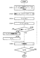
図14は、上記のような構成の娯楽システムの動作を説明するためのフローチャートを示している。
【0109】
即ち、携帯ゲーム機本体としてのプログラム処理装置300の電源スイッチ(図示せず)が投入されると、読取装置本体100のCPU107は、システムROM112のプログラムに基づいてこの動作をスタートする。そして、まず、上記媒体センサ111の出力に基づいて遊戯カードとしての記録媒体400の挿入検出があったか否か(或いは、上記操作釦110の操作による操作指示情報があるか否か)を判断する(ステップS11)。ここで、挿入検出のない場合には、媒体センサ111が遊戯カードとしての記録媒体400を検出するまで待機する。
【0110】
これに対して、遊戯カードとしての記録媒体400がスリット131に挿入されると、媒体センサ111が遊戯カードとしての記録媒体400を検出する。これに応じて、CPU107は、上記照明用LED101を点灯駆動する(ステップS12)。そして、コード401の形成されている辺に沿うように、操作者が記録媒体400をスリット131の底の走査ガイド133に当て付けながらの移動を開始するので(ステップS13)、CPU107は、上記撮像素子103によって上記記録媒体400上のコード401を撮像させ(ステップS14)、その撮像結果を上記2値化回路105に2値化させて、2値化メモリに2値画像として取り込ませる(ステップS15)。その後、前述したようにして、この2値画像よりデータ読取位置を決定して(ステップS16)、データを読み取り(ステップS17)、元のデータに復元して(ステップS18)、ゲームカートリッジとしてのアプリケーションプログラム格納カートリッジ200のRAM202にその復元されたデータを書き込む。また、この処理の途中で得られた、前述したようなパラメータもRAM202に格納される。
【0111】
そしてここで、遊戯カードとしての記録媒体400の移動が終了したか否か(或いは、上記操作釦110の操作による操作指示情報がなくなったか否か)が判断され(ステップS19)、まだ媒体センサ111が記録媒体400の検出期間中であれば前述のステップS14へ戻り、記録媒体400を検出しなくなるまでステップS14〜S19の動作が繰り返される。つまり、このステップS14〜S19の動作は、コード401に記録されている全てのブロックのデータが読み出されるまで繰り返される。
【0112】
而して、ステップS19において、遊戯カードとしての記録媒体400の移動終了が検出されると、照明用LED101が消灯される(ステップS20)。そして、上記RAM202に記憶されている、1枚の遊戯カードとしての記録媒体400のコード401から読み取られたデータ及び処理途中で得られたパラメータは、携帯ゲーム機本体としてのプログラム処理装置300のCPU302によって順次読み出されて、RAM304に一時記憶される(ステップS21)。そして、CPU302は、このRAM304に記憶されている読取データを解析し(ステップS22)、その解析後の読取データとゲームカートリッジとしてのアプリケーションプログラム格納カートリッジ200のROM201に記憶されているプログラムとに基づいて、本来のゲーム処理に基づく処理に対して解析後の読取データに応じたランダム性を加えた処理を行う(ステップS23)。このランダム性を加えた処理としては、例えばコード401に記録されているデータがテキストデータであれば、読み取った文字又は文章をLCD306に表示するが、その際に、パラメータに応じてフォントを変えたり、語尾を変化させる等の処理が行われる(ステップS23A)。また、コード401に記録されているデータがキャラクタを表示するためのグラフィック(又はドット)データであれば、そのグラフィックデータがLCD306に表示されるが、その際、パラメータに応じて表示間隔を変えたりするランダム性を加える(ステップS23B)。さらに、コード401に記録されているデータがモンスターの鳴き声等の音声データであれば、音声データがD/A変換されて音声出力部307から音声として出力されるが、その際、パラメータに応じて音声の出力時間を変える等のランダム性を加える(ステップS23C)。
【0113】
次に、上記パラメータに応じてどのうよにしてランダム性が付加されるかを、例えば、上記エラー訂正数のパラメータを使う場合を例に、より詳細に説明する。
【0114】
今、遊戯カードとしての記録媒体400には、図13の(B)に示す論理形式でデータがコード401として記録されており、このコード401から読み取られたデータは、エラーがある場合にはエラーを訂正され、著しくエラーが多い場合を除いてデータが読み出されることが保証されている。
【0115】
ここで、データ部には、画像データが収容され、これに画像データのもう一つの要素であるアニメーションパターンが加わって、アニメーションパターン通りの動きをLCD306に表示するように構成されている。また、記録媒体400のコード401の読み取り時に検出したエラー訂正数(エラーレート)がCPU107からCPU302にRAM202,304を介して伝えられるようになっている。
【0116】
また、ゲームカートリッジとしてのアプリケーションプログラム格納カートリッジ200のROM201には、図13の(C)に示すように、エラーレートとアニメーションパターンの組が記憶されている。ここで、例えば、アニメーションパターン[0]には弱いアニメーションを、パターンが[1],[2],[3],…となるにつれて力強いアニメーションにすることにより、使い込むに従ってキャラクタが強くなるカードとなる遊びが実現できる。
【0117】
このようなアニメーションパターンをROM201に持つ場合、携帯型ゲーム機本体としてのプログラム処理装置300のCPU302は、上記ゲームカートリッジとしてのアプリケーションプログラム格納カートリッジ200のROM201に記憶されたゲームプログラムに従って、図15に示すようにして、アニメーションを実現する。
【0118】
即ち、この場合には、前述のステップS21に相当する処理として、上記コード401から読み取られたキャラクタデータと、そのキャラクタデータ取得の処理中に得られたパラメータであるエラーレートEとを、アプリケーションプログラム格納カートリッジ200のRAM202から読み出して、RAM304に記憶する(ステップS111)。なお、この例では、ROM201に記憶されている情報により、コード401から読み出されるデータがキャラクタデータであることが予め判っているので、上記ステップS22の読み取りデータの解析処理は省略される。
【0119】
そして、CPU302は、内部カウンタα(図示せず)に初期値として「0」をセットし(ステップS112)、その後、その内部カウンタαの値で示されるエラーレート[α]と上記RAM304に記憶したエラーレートEとを比較し、エラーレートEがエラーレート[α]以上であるか否かを判別する(ステップS113)。
【0120】
ここで、エラーレートEがエラーレート[α]以上でない場合には、上記内部カウンタαの値を「+1」する(ステップS114)。そして、その「+1」後の内部カウンタαの値が上記ROM201に記憶されているエラーレートとアニメーションパターンの組の数nを越えたか否かを判別し(ステップS115)、まだ越えていなければ上記ステップS113に戻る。これに対して、上記組の数nを越えてしまった時には、所定のエラー表示出力やエラー音声の出力を行うことになる。
【0121】
また、エラーレートEがエラーレート[α]以上となった場合には、上記ステップS113においてYESと判定され、この場合には、そのエラーレート[α]に対応するアニメーションパターン[α]をアプリケーションプログラム格納カートリッジ200のROM201から読み出し、それを上記RAM304に記憶されているキャラクタデータと組み合わせて表示することにより、アニメーション表示を行う(ステップS116)。
【0122】
このように、遊戯カードとしての記録媒体400のコード401から読み取られるキャラクタデータは一つであるにもかかわらず、その読み取りのエラーレートEに応じて複数のアニメーションパターンの一つを選択することで、異なるアニメーションが表示される。
【0123】
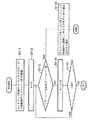
また、13の(C)に示すようなアニメーションパターンを持たずに、プログラムそのものでアニメーションを実現することも可能である。この場合は、CPU302は、ROM201に記憶されたゲームプログラムに従って、図16の(A)に示すように動作する。
【0124】
即ち、この場合には、上記コード401から読み取られたキャラクタデータと、そのキャラクタデータ取得の処理中に得られたパラメータであるエラーレートEとを、アプリケーションプログラム格納カートリッジ200のRAM202から読み出して、RAM304に記憶する(ステップS121)。
【0125】
そして、そのRAM304に記憶したエラーレートEを、ROM201に記憶されたゲームプログラムにより与えられる2つのエラーレート定数β1,β2と比較する(ステップS122)。
【0126】
ここで、エラーレートEが第1のエラーレート定数β1以下であれば、上記ROM201に記憶されたゲームプログラムのアニメーション1サブルーチンが実行され(ステップS123)、上記RAM304に記憶されているキャラクタデータを用いた第1のアニメーション表示が行われる。
【0127】
また、エラーレートEが上記第1のエラーレート定数β1よりも大きいが第2のエラーレート定数β2以下であれば、上記ROM201に記憶されたゲームプログラムのアニメーション2サブルーチンが実行され(ステップS124)、上記RAM304に記憶されているキャラクタデータを用いた第2のアニメーション表示が行われる。
【0128】
そして、エラーレートEが上記第2のエラーレート定数β2よりも大きければ、上記ROM201に記憶されたゲームプログラムのアニメーション3サブルーチンが実行され(ステップS125)、上記RAM304に記憶されているキャラクタデータを用いた第3のアニメーション表示が行われる。
【0129】
このように、遊戯カードとしての記録媒体400のコード401から読み取られるキャラクタデータは一つであるにもかかわらず、その読み取りのエラーレートEに応じてプログラムの動きを選択することで、異なるアニメーションが表示される。
【0130】
また、図17に示すように、エラーレートEの大きさに従い、アニメーションのフレームレート、つまりアニメーションの動くスピードを変化させるよう構成することも可能である。
【0131】
即ち、まず、上記コード401から読み取られたキャラクタデータと、そのキャラクタデータ取得の処理中に得られたパラメータであるエラーレートEとを、アプリケーションプログラム格納カートリッジ200のRAM202から読み出して、RAM304に記憶する(ステップS131)。
【0132】
そして、このRAM304に記憶したエラーレートEで、ROM201に記憶されたゲームプログラムにより与えられる定数Fを割り、その結果の値を書替インターバルとして内部レジスタに記憶する(ステップS132)。また、内部カウンタTに初期値として「0」をセットすると共に、内部カウンタAに初期値として「0」をセットする(ステップS133)。
【0133】
その後、上記内部カウンタTの値を「+1」すると共に、内部カウンタAの値を「+1」する(ステップS134)。そして、その内部カウンタAの値が上記内部レジスタに記憶した書替インターバルよりも小さいか否かを判別する(ステップS135)。
【0134】
ここで、内部カウンタAの値が書替インターバルよりも小さい場合には、上記RAM304に記憶されているキャラクタデータを用いた一画面表示を行う(ステップS136)。そしてその後、上記内部カウンタTの値が150以下であるか否かを判別し(ステップS137)、そうであれば、上記ステップS134に戻る。
【0135】
また、上記ステップS135で、内部カウンタAの値が書替インターバル以上となったと判別された時には、上記RAM304に記憶されているキャラクタデータの画像を書き替える(ステップS138)。そして、上記内部カウンタAの値を「0」にリットとした後(ステップS139)、上記ステップS136に進み、その書き替えられたキャラクタデータを用いた一画面表示を行うことになる。
【0136】
こうして、上記ステップS137で上記内部カウンタTの値が150を越えるまで、上記処理が繰り返される。
【0137】
即ち、画像は30分の1秒毎に一回書き替えを行うようになっており、上記書替インターバルは、その30分の1秒毎の画面書き替えの何回毎にキャラクタデータに変更を加えるかを示している。エラーレートEが大きくなると、この書替インターバルが小さくなり、頻繁に書き替えられるため、アニメーションが早く動くようになる。このフローチャートにおいては、150フレームつまり5秒間ループをして、処理を終了するようになっている。
【0138】
このように、遊戯カードとしての記録媒体400のコード401から読み取られるキャラクタデータは一つであるにもかかわらず、その読み取りのエラーレートEをプログラムパラメータとして使用することでプログラムの動作を変化させ、異なるアニメーションが表示される。
【0139】
なお、上記アニメーションパターンデータや図15,図16の(A)及び図17のフローチャートで示された動作を行うプログラムを、ROM201に収納せずに記録媒体400上のコード401に収納し、RAM202を介してRAM304に転送して動作させる構成でも実現できる。即ち、基本的には、図13の(C)に括弧書きで示すように、ROM201をRAM202に置き換えるだけで良い。
【0140】
このようにコード401に記録する場合には、これらの情報を置くスペースが記録媒体400に必要となるために、記録媒体400上の他のスペース、即ち図柄表示領域431及び能力データ記録領域432が圧迫されるというデメリットがある一方で、アメーションパターンやプログラムが、ゲームカートリッジとしてのアプリケーションプログラム格納カートリッジ200側のROM201内に固定化されず、コード401として記録されるデータを変更することにより様々に変化させることができるので、非常に柔軟性に富んだ娯楽を提供することができる。
【0141】
また、上記エラーレートのパラメータを前述したような別のパラメータとしても、同様に、コードの読み取り結果にランダム性を付与できる。
【0142】
以上詳述したように、本第1の実施の形態によれば、記録媒体またはコード読取装置または操作者または読取環境において、同一の条件であれば同一の結果が得られつつ、この条件が異なる時にはランダム性を有する多様な結果が得られるという効果を奏することができる。
【0143】
例えば、トレーディングカードと呼ばれる収集を目的とするカードに光学的に読み取り可能なコードを付加し、そのコードを読み取らせて結果の画像を画面に表示させて楽しむ娯楽システムにおいて、遊びに変化を持たせようとした場合、従来のようにコードを読み込ませる毎にプログラムで乱数を発生させ、その乱数によって遊びに変化を持たせる方法を取ると、この方法はプログラムであるために変化を容易に発生させることができるが、その一方で、ある任意の表示画面は、繰り返し操作を行えば誰でもそれを見ることができ、遊びの幅が広がらないものとなってしまっていた。また、一度見ることができたその任意の表示画面をユーザがもう一度見ようとしても、乱数に基づくために再現性はなく、同じ画像を表示させるためにはコード読み取り操作を繰り返し行うしかなく、ユーザにフラストレーションを与える原因になってしまっていた。
【0144】
一方、カードに印刷されたコードは、カードの印刷の具合や、汚れや劣化などによるデータ欠落やなどにより、カード毎に異なる特性を持っている。また、コード読取装置も、機械的、電子的な製造上のバラツキがあり、そのためにそのバラツキを修正する調整値や読み取り時の自動調整値は、コード読取装置毎に異なる特性を持っている。読み取り操作を行う環境条件においても、温度や、コード読取装置に入り込む外来光などによって変化する特性を持っている。さらに、人間がカードを操作する際に、カードの走査方向や、速度や、手ぶれや、コードが複数ある場合にはそれを読み取る順番など、人毎に異なる癖があり、異なる特性が得られる。
【0145】
本実施の形態を使用することにより、コードを読ませる時に得られるこれらの異なる特性を活用することで、ランダム性を持つ多種多様な変化を生成する娯楽システムを提供することができ、カードの違い、コード読取装置の違い、環境条件の違い、操作者の違いにより、個性や変化が付けられようになり、ユーザの遊びの幅を広げられるという効果が得られる。
【0146】
特に、具体的な効果としては次のようなものがある。
【0147】
1:トレーディングカードは、色々なカードを集めたり交換したりすることや、お互いに情報を交換することが楽しみの中心となる。本実施の形態によれば、カードに印刷されたコードのバラツキにより多様な結果を生成することができ、同じ種類のカードでも自分の持っている物と友人の持っている物とで異なる結果が得られ、カードを交換する楽しみ、収集する楽しみを強化することができる。
【0148】
2:コードのドットの大きさや輝度情報の違いにより、結果が変化するように娯楽システムを構成しておくことにより、印刷時にインクの乗りや濃度を積極的に変えていくことにより、コストが掛かるデータや版下に変更を加えることなく動作の異なる多様なカードを作成することができるようになり、容易にカードのバリエーションを増やすことができる。
【0149】
3:また、本実施の形態によれば、コード読取装置のバラツキによっても、多様な結果を生成することができ、同一のカードでも自分の持っているコード読取装置と友人の持っているコード読取装置で異なる結果が得られるようになり、お互いに自分のカードを相手のコード読取装置に読み取らせてどのような結果が出てくるかを試して楽しむ、という遊びを生み出すことができる。またこの場合、コード読取装置に通信機能を持たせれば、自分のカードを相手のコード読取装置に読み取らせて得られた結果を、自分のコード読取装置に取り込むという使用法も考えられる。
【0150】
4:同様に、本実施の形態によれば、操作者の癖に依存するものであるカードをコード読取装置に読み込ませる時の操作方法の違いにより、操作者によって異なる結果が得られるようになり、同一カード同一装置であっても人によって出力されるものが異なるようになる。例えばモンスターが描かれているカードに、それが画面で演技をするように構成されていた場合、同じモンスターが人によって演技が異なるようになり、「友人のモンスターはのろまだが、自分のモンスターはせっかちだ」というような、人とは違う自分だけのモンスターへの愛着心を育むことができ、モンスターと自分との一体感を演出することができる。
【0151】
5:更に、本実施の形態によれば、カードをコード読取装置に読み込ませるための環境条件の違いにより、異なる結果を得られるようになり、外来光が多い時に読み込ませると、モグラのようなモンスターは出現しない、という演出をすることができる。或いは、氷系,火系,草系等のモンスターの種類があるとき、GPS等で得た位置が北国であるとか、測定した温度が低いというときに、氷系のモンスターが強くなる等の演出をすることも可能である。
【0152】
6:同様に、本実施の形態によれば、エラーによるデータ欠損量が増えるに従い最初はそのカードの力が強く、その後弱くなるように変化する娯楽システムを構成することができ、欠損量はカードを使い込むに従って増えることから、画面上のアニメーションあるいはゲーム上の能力が、使い込むに従って最初は成長して強いモンスターとなり、そのうちに老化した弱いモンスターになるというような演出や遊びを付加することができる。
【0153】
7:更に、エラーを活用するものにおいては、エラーによりコードデータを取得できなかった場合に、エラーの量や内容により色々な演出を行うように構成することにより、通常であればユーザのフラストレーションの元となるエラーそのものも遊びにすることができ、ユーザの楽しみの拡大を図ることができる。
【0154】
[第2の実施の形態]
次に、本発明の第2の実施の形態を説明する。
【0155】
上記第1の実施の形態においては、コードの読み取り結果に、その読み取り処理中に得られたパラメータに応じてランダム性を付加するようにしているが、例えば、移動速度等の人間にとって予測可能なものについては、最高速度や平均速度といった値をそのままパラメータとして使用したのでは、操作者に与えるランダム性のインパクトが弱い。
【0156】
そこで、本第2の実施の形態では、更にランダム性の度合いを増すための構成を付加するものである。
【0157】
即ち、ゲームカートリッジとしてのアプリケーションプログラム格納カートリッジ200のROM201に、最高速度や平均速度といった速度の値ではなくて、図18の(A)に示すように、その速度の変化の状態を示す速度パターンを複数記憶しておく。そして、同図の(B)に示すように、測定した速度の変化パターンを、上記ROM21に記憶された速度パターンと同様の単位時間となるよう正規化し、それを上記記憶されている各パターンと順次パターンマッチングして、最も近い速度パターンをパラメータとして選択する。
【0158】
或いは、図16の(B)に示すように、測定した速度範囲の値に応じて、昇順や降順ではないパラメータ値が得られるようなテーブルを、ゲームカートリッジとしてのアプリケーションプログラム格納カートリッジ200のROM201に記憶、もしくは、コード401に記録しておくようにしても良い。
【0159】
なお、このような構成は、上記速度パラメータ以外の他のパラメータについても、同様に適用することが可能なことは勿論である。
【0160】
このように、本第2の実施の形態によれば、更にランダム性を増すことができるという効果を奏することができる。
【0161】
以上実施の形態に基づいて本発明を説明したが、本発明は上述した実施の形態に限定されるものではなく、本発明の要旨の範囲内で種々の変形や応用が可能なことは勿論である。
【0162】
例えば、上記実施の形態では、プログラム処理装置300をLCD付の携帯ゲーム機とした場合について説明したが、この発明の技術思想はこれに限定されるものではなく、ビデオゲーム機やパソコンを使用するゲームにも適用可能である。その場合は、ゲームカートリッジとしてのアプリケーションプログラム格納カートリッジ200のROM201の記憶データがビデオゲーム機用の情報記憶媒体、例えばメモリカートリッジ,磁気ディスク,CD−ROM,又はDVD(ディジタル多用途ディスク)等に記憶され、読取装置本体100がビデオゲーム機又はパソコンに一体的に又は外付けで接続されることになる。
【0163】
また、上述の実施の形態では、電子ゲームの内容の一例として、モンスターを捕獲・育成・収集等するゲームの場合を説明したが、この発明の技術思想は、実施の形態のゲームに限定されるものではなく、遊戯カードと電子ゲームを組み合わせたゲームであれば、任意のゲームに適用可能であることを指摘しておく。
【0164】
なお、キャラクタの識別コードは、キャラクタ毎に1個に限ることなく、同一キャラクタでも個性表現データが異なる複数種類のカードが存在する場合であれは、1つのキャラクタにつき複数個の識別データを持つようにしても良い。
【0165】
また、本発明は、上記実施の形態で説明したような娯楽システムだけでなく、教育機器等、その他のシステムにも利用可能なことは勿論である。
【0166】
【発明の効果】
以上詳述したように、本発明によれば、コード読取装置において、そのコードの読み取り結果にランダム性を付与するためのランダム性付与手段を具備することにより、操作者に対して、コードの読み取り操作に対する結果の意外性を簡単に提示できるようにし、もって、ゲーム機器等の娯楽システムや教育機器に好適に応用できるようにしたコード読取装置を提供することができる。
【0167】
また、本発明によれば、そのランダム性を活用し、遊びに豊富な変化を与えて操作者の楽しみを拡張する娯楽システムを提供することができる。
【図面の簡単な説明】
【図1】(A)は本発明の第1の実施の形態に係るコード読取装置の構成を示す図、(B)はワンショット撮像可能なコードを示す図であり、(C)は遊戯カードとしての記録媒体を示す図である。
【図2】(A)は読取装置本体の機能ブロック図、(B)は記録媒体に記録されたコードの例を示す図であり、(C)は読取装置本体の各機能ブロックから取得できる情報を説明するための図である。
【図3】(A)は多値画像情報から得られる輝度情報に関するパラメータを説明するための図であり、(B)は2値画像情報から得られる画素属性に関するパラメータを説明するための図である。
【図4】(A)はコード位置・形状情報から得られる位置・形状に関するパラメータを説明するための図、(B)はコードデータ情報から得られるコードデータに関するパラメータを説明するための図であり、(C)は復元情報から得られる復元情報に関するパラメータを説明するための図である。
【図5】(A)及び(B)はそれぞれ一般的なコードを示す図、(C)は複数のブロックからなるコードを示す図であり、(D)はドットコードのブロックの構成例を示す図である。
【図6】(A)は2値化手段の構成と取得できる情報を示す図、(B)はデータ読取位置決定手段の構成と取得できる情報を示す図、(C)はアドレス検出手段を含む構成を示す図であり、(D)はデータ復元手段の構成と取得できる情報を示す図である。
【図7】(A)は記録媒体を把持して手動走査を行う場合の構成を示す図、(B)は読取装置本体を把持して手動走査を行う場合の構成を示す図であり、(C)は相対移動方向、回数に関するパラメータの検出方法を説明するための図である。
【図8】(A)は記録媒体に記録されたコードと撮像領域との関係を示す図、(B)はある時点での撮像画面を示す図、(C)は次の撮像での撮像画面を示す図であり、(D)は相対移動速度に関するパラメータの検出方法を説明するための図である。
【図9】(A)は読取装置本体を把持して手動走査を行う様子を示す図、(B)はある時点での撮像画面を示す図、(C)は次の撮像での撮像画面を示す図、(D)は各撮像時点での撮像領域に対するコードの関係を示す図であり、(E)は蛇行性に関するパラメータの検出方法を説明するための図である。
【図10】(A)は走査ガイドと撮像素子の組み付け位置関係を示す図、(B)はレンズ倍率に関するパラメータの取得方法を説明するための図、(C)は走査ガイド位置に関するパラメータの取得方法を説明するための図、(D)は照明状態に関するパラメータの取得方法を説明するための図であり、(E)は結像レンズの歪み状態に関するパラメータの取得方法を説明するための図である。
【図11】ランダム性を出すために効果的なパラメータの例をまとめて示す図である。
【図12】(A)はマスキングカード及びデータカードを示す図、(B)はマスキングカードとデータコードとを重ね合わせた状態を示す図であり、(C)は制御コードの読取に応じてコード読取結果に付加されるランダム性を説明するための図である。
【図13】(A)は第1の実施の形態に係るコード読取装置を娯楽システムに適用した場合の構成を示す図、(B)はコードの論理フォーマットを示す図であり、(C)はゲームカートリッジとしてのアプリケーションプログラム格納カートリッジのROMの記憶データを示す図である。
【図14】娯楽システムの動作を説明するためのフローチャートを示す図である。
【図15】娯楽システムにおける携帯型ゲーム機本体としてのプログラム処理装置のCPUの動作を説明するためのフローチャートを示す図である。
【図16】(A)はプログラム処理装置のCPUの動作の別の例を説明するためのフローチャートを示す図であり、(B)は第2の実施の形態に係るコード読取装置における速度に関するパラメータ取得のために用いられるアプリケーションプログラム格納カートリッジのROMの記憶データを説明するための図である。
【図17】プログラム処理装置のCPUの動作の更に別の例を説明するためのフローチャートを示す図である。
【図18】(A)は本発明の第2の実施の形態に係るコード読取装置におけるアプリケーションプログラム格納カートリッジのROMの記憶データを説明するための図であり、(B)は速度に関するパラメータの取得方法を説明するための図である。
【符号の説明】
100 読取装置本体
101 照明用LED
102 結像レンズ
103 撮像素子
105 2値化回路
106 2値化メモリ
107,302 CPU
110 操作釦
111 媒体センサ
121 画像入力手段
122 2値化手段
122A 輝度情報検出手段
122B 閾値制御手段
122C 2値判定手段
123 データ読取位置決定手段
123A コード指標検出手段
123B 位置決め指標検出手段
123C データ読取位置算出手段
124 データ読取手段
125 データ復元手段
125A 復調手段
125B エラー訂正情報抽出手段
125C エラー訂正手段
126 アドレス検出手段
200 アプリケーションプログラム格納カートリッジ
201,303 ROM
202,304 RAM
203 環境検出センサ
204 コネクタ
300 プログラム処理装置
301 コネクタ
305 操作部
306 LCD
307 音声出力部
400 記録媒体
401 コード[0001]
BACKGROUND OF THE INVENTION
The present invention relates to a code reader that optically reads a code from a recording medium in which data is recorded as an optically readable code, and such a recording medium and entertainment using such a code reader. About the system.
[0002]
[Prior art]
Various types of code readers are known that optically read a code from a recording medium that records data as an optically readable code, for example, a one-dimensional or two-dimensional bar code.
[0003]
[Problems to be solved by the invention]
In the conventional code reading apparatus as described above, the information to be output is determined almost unambiguously for the code reading operation by the operator. When applied, only a simple way of playing and a mechanical learning method can be provided, and there is a certain limit to increasing interest or intriguing the operator.
[0004]
The present invention has been made in view of the above points, and one object of the present invention is to provide a code reader with randomness imparting means for imparting randomness to the code reading result. Accordingly, it is possible to easily present the unexpectedness of the result of the code reading operation to the operator, and to provide a code reading device that can be suitably applied to entertainment systems such as game machines and educational equipment. There is.
[0005]
Another object of the present invention is to provide an entertainment system that utilizes the randomness and gives abundant changes in play to extend the enjoyment of the operator.
[0006]
[Means for Solving the Problems]
In order to achieve the above object, a code reading device according to the present invention provides a code reading device that optically reads the code from a recording medium on which data is recorded as an optically readable code. Randomness imparting means for imparting randomness is provided.
Alternatively, the code reading device according to the present invention is a code reading device for optically reading the code from a recording medium in which data is recorded as an optically readable code, for imparting randomness to the code reading result. Randomness imparting means is provided, and the randomness imparting means includes parameter detection and randomness imparting means for imparting randomness to the reading result by detecting a parameter related to reading of the code.
Furthermore, the code reading device according to the present invention is a code reading device for optically reading the code from a recording medium in which data is recorded as an optically readable code, for imparting randomness to the code reading result. Randomness imparting means is provided, and the randomness imparting means includes detection and imparting means for imparting randomness to the read result by detecting a parameter relating to the recording medium.
The code reader according to the present invention is a code reader for optically reading the code from a recording medium in which data is recorded as an optically readable code, for imparting randomness to the code reading result. Randomness imparting means is provided, and the randomness imparting means includes detection and imparting means for imparting randomness to the read result by detecting a parameter specific to the code reader of the device itself.
Alternatively, the code reading device according to the present invention is a code reading device for optically reading the code from a recording medium in which data is recorded as an optically readable code, for imparting randomness to the code reading result. Randomness imparting means is provided, and the randomness imparting means includes means for imparting randomness to a read result by detecting a parameter relating to a positional relationship between predetermined constituent elements constituting the code. To do.
Furthermore, the code reading device according to the present invention is a code reading device for optically reading the code from a recording medium in which data is recorded as an optically readable code, for imparting randomness to the code reading result. Randomness imparting means is provided, and the randomness imparting means includes means for imparting randomness to the read result by detecting a parameter relating to luminance information of a predetermined component constituting the code. .
The code reader according to the present invention is a code reader for optically reading the code from a recording medium in which data is recorded as an optically readable code, for imparting randomness to the code reading result. Randomness imparting means is provided, and the randomness imparting means includes means for imparting randomness to the read result by detecting a parameter relating to the size of a predetermined component constituting the code. .
Alternatively, the code reading device according to the present invention is a code reading device for optically reading the code from a recording medium in which data is recorded as an optically readable code, for imparting randomness to the code reading result. Randomness imparting means is provided, and the randomness imparting means includes means for imparting randomness to the read result by detecting a parameter relating to the shape of a predetermined component constituting the code.
Furthermore, the code reading device according to the present invention is a code reading device for optically reading the code from a recording medium in which data is recorded as an optically readable code, for imparting randomness to the code reading result. Randomness imparting means is provided, and the randomness imparting means includes means for imparting randomness to the read result by detecting a parameter relating to missing information missing from the read code.
[0007]
An entertainment system can be configured using the code reader.
[0008]
In the recording medium according to the present invention, data including information to be added with randomness and a plurality of pieces of information used for adding randomness is recorded as an optically readable code. The output of the information to be added with the read randomness is changed by selecting from the plurality of information used for adding the randomness read from the recording medium by being read by the reading device. It is characterized by being.
[0009]
Alternatively, in the recording medium according to the present invention, data including information to be added with randomness and a program capable of selecting a plurality of movements are recorded as an optically readable code, and the code is read by the code reader. The movement of the program is selected and the output of the information to which the read randomness is to be added is changed.
[0010]
Furthermore, in the recording medium according to the present invention, data including information to be added with randomness and a program for handling program parameters is recorded as an optically readable code, and the code is read by a code reader. Thus, the output of the information to which the read randomness should be added is changed by changing the program parameter and thereby changing the operation of the program.
[0011]
That is, according to the code reading device, the entertainment system, and the recording medium of the present invention, randomness can be given to the code reading result, so that the unexpectedness of the result with respect to the code reading operation can be simplified for the operator. Can be presented.
[0012]
DETAILED DESCRIPTION OF THE INVENTION
Hereinafter, embodiments of the present invention will be described in detail with reference to the drawings.
[0013]
[First Embodiment]
FIG. 1A is a diagram showing a configuration of a code reading apparatus according to the first embodiment of the present invention.
[0014]
In other words, the code reading device includes a reading device
[0015]
Here, the
[0016]
The analog video signal from the image sensor 103 is converted into a multi-value image signal by the A /
[0017]
The
[0018]
The control operation of each part by the
[0019]
The
[0020]
The
[0021]
Although details will be described later, the
[0022]
The
[0023]
On the other hand, the
[0024]
The
[0025]
The
[0026]
The
[0027]
Although not specifically shown, power to each unit in the application
[0028]
The
[0029]
The
[0030]
In the case where the
[0031]
Thus, in the code reading device configured as described above, the
[0032]
The above operation is the same as that of the conventional code reading device. However, in the code reading device according to the present embodiment, the reading device
[0033]
Below, the means for imparting such randomness and the contents of the randomness will be described in order.
[0034]
First, means for imparting randomness will be described.
[0035]
The function of the reading apparatus
[0036]
For example, as shown in FIG. 2B, the
[0037]
These multi-value image information, binary image information, code position / shape information, code data information, and restoration information are stored in the
[0038]
Here, from the multi-valued image information, the parameters of maximum luminance, minimum luminance, or average luminance can be obtained by detecting the luminance of each pixel as shown in the upper right in FIG. . Alternatively, the black median, white median, or extreme parameter can be obtained by detecting the frequency of occurrence of each luminance as shown in the lower right in the figure. Furthermore, it is also possible to provide a predetermined area in the imaging area as shown in the lower left in the figure, and obtain the respective average luminance parameters. Of course, it is also possible to obtain parameters such as maximum luminance and black median in such a predetermined area.
[0039]
Further, from the binary image information, it is possible to obtain parameters of the occurrence frequency of black pixels and white pixels as shown in the upper right in FIG. Alternatively, as shown in the lower right in the figure, a pixel attribute parameter indicating whether the pixel at the predetermined position is a black pixel or a white pixel can be obtained. Furthermore, as shown in the lower left of the figure, it is possible to obtain a pixel distribution parameter of a predetermined area such as what percentage of black pixels and white pixels are present in the predetermined area.
[0040]
Further, from the code position / shape information, it is possible to obtain the parameters of the position, size, or shape of the code components as shown in the upper right in FIG. Alternatively, it is possible to obtain data reading position parameters as shown in the lower right in the figure. Furthermore, as shown in the lower left in the figure, it is also possible to obtain a parameter for the number of detected code components, for example, the
[0041]
Further, from the code data information, as shown in FIG. 4B, the number of 0s, the number of 1s, the inverted number of 0s and 1s, the data length, the number of 0s and 1s for each predetermined length, Parameters such as the number of continuations and the number of continuations of 1 can be obtained.
[0042]
From the restoration information, as shown in FIG. 4C, the type of information (whether it is a picture, a character, a sound, etc.), the length of information (number of bytes, time, Etc.), information content (creator, code, ID of recording medium, etc.), etc. can be obtained.
[0043]
As the
[0044]
Here, in the two-dimensional code as shown in FIG. 5A,
[0045]
Further, the one-dimensional barcode as shown in FIG. 5B is configured such that a
[0046]
Furthermore, by adding address information to the code as shown in FIG. 5A and making it into a block, a code consisting of a plurality of blocks as shown in FIG. 5C can be configured.
[0047]
Further, as such a code composed of a plurality of blocks, a dot code as disclosed in JP-A-8-171620 is known. As shown in FIG. 5D, each block has block data 404A in which dot images corresponding to data to be recorded are present in a predetermined two-dimensional array. A
[0048]
The binarization means 122 can be composed of a luminance information detection means 122A, a threshold control means 122B, and a binary determination means 122C, as shown in FIG. Of course, the luminance information detection means 122A and the threshold control means 122B are actually constituted by the
[0049]
That is, the luminance information detection unit 122A detects the luminance of the multi-value image information from the
[0050]
According to such a configuration, the luminance information is obtained from the luminance information detecting unit 122A, and thereby, for example, parameters such as the maximum value of luminance as described above can be extracted. Further, threshold information is obtained from the threshold control means 122B.
[0051]
When a code having a positioning index as shown in FIG. 5A or FIG. 5D is used as the
[0052]
That is, the code index detection unit 123A detects the image of the code index 402 (
[0053]
According to such a configuration, the position, number, and shape information of the code index is obtained from the code index detection means 123A, and the position, number, and shape information of the positioning index is obtained from the positioning index detection means 123B. Will be obtained.
[0054]
When a code composed of a plurality of blocks as shown in FIG. 5C or FIG. 5D is used as the
[0055]
That is, in parallel with reading the data at the data reading position determined by the data reading position determining means 123 by the data reading means 124, the address detecting means 126 detects the address of the block containing the data. In the data restoring means 125, the data read by the data reading means 124 is rearranged based on the address detected by the
[0056]
In this case, address information can be obtained from the
[0057]
In general, the code data may be modulated or error correction data may be added. When such a code is used, the data restoring means 125 in FIG. As shown in FIG. 4D), it comprises a demodulation means 125A, an error correction information extraction means 125B, and an error correction means 125C.
[0058]
That is, for example, as disclosed in JP-A-6-231466, when data is recorded as an optically
[0059]
In such a configuration, demodulated data information is obtained from the demodulation means 125A, and error correction information such as the number of error corrections and correction positions is obtained from the error correction information extraction means 125B.
[0060]
On the other hand, when the
[0061]
Alternatively, as shown in FIG. 7B, the
[0062]
When the code is manually scanned in this way, the following information can also be acquired.
[0063]
That is, as shown in FIG. 8A, using the
[0064]
Further, an acceleration parameter is obtained by differentiating the calculated relative movement speed.
[0065]
Alternatively, as shown in FIG. 9 (A), a
[0066]
Further, when a
[0067]
Further, parameters relating to the code reader can be obtained as follows.
[0068]
That is, when the reader
[0069]
At this time, as shown in FIG. 10B, by using the information on the reading position of the
[0070]
Alternatively, as shown in FIG. 10C, a parameter related to the position of the scanning guide 133 can be obtained by detecting the distance from the screen edge of the imaging screen to the
[0071]
Further, as shown in FIG. 10D, by detecting luminance information (in this case, information on the average luminance for each predetermined area), parameters relating to the illumination state of the
[0072]
Up to this point, the types of parameters that can be detected and the detection methods thereof have been described. FIG. 11 summarizes examples of parameters that are effective for achieving randomness. That is, the detected information, the parameters obtained from the information, and the parameters are any of “parameters relating to reading”, “parameters relating to reading”, “parameters relating to the recording medium”, and “parameters relating to the reading device”. It is shown in list form whether it is particularly effective.
[0073]
Note that the “parameters relating to reading” are parameters that can be used on the same recording medium so that the result can be controlled according to the way the operator operates. Further, the “parameters relating to the recording medium” are parameters that can be used in such a manner that the output of the result is controlled by the read medium even when the same operation is performed by the same reading apparatus. The “parameters relating to the reading device” are parameters that can be used in such a way that the reading device controls the output of the result even if the same operation is performed on the same recording medium.
[0074]
In other words, if environmental information is detected, reading environment parameters such as temperature, humidity, time, position, atmospheric pressure, etc. are obtained, and these parameters are particularly effective when used as “parameters relating to reading” or “parameters relating to reading devices”. is there. Further, as the environmental information, it is possible to obtain parameters of the power supply rise time and the power supply voltage, and these parameters are particularly effective when used as “parameters relating to the reading device”.
[0075]
On the other hand, if multi-value image information is detected, parameters such as maximum luminance, minimum luminance, average luminance, luminance distribution, average luminance of a predetermined area, and the like are obtained. These parameters are, for example, a pen-shaped reading device
[0076]
Further, when threshold information is detected, a threshold parameter is obtained, which varies depending on the recording density of the recording medium and the illumination amount of the reading device, and is used as a “parameter relating to the recording medium” and “parameter relating to the reading device”. Is particularly effective.
[0077]
On the other hand, if binary image information is detected, parameters such as the number of black pixels, the number of white pixels, the ratio of white / black pixels, and the like can be obtained. Since these parameters depend on the code and the surrounding design, It can be used as a parameter. In particular, the black pixel number parameter is also related to the illumination amount and the shading amount, and can therefore be used as a “parameter relating to the reading apparatus”.
[0078]
Further, if the code index (positioning index) position / number / shape information is detected, the code index (positioning index) detection position, the number of code index (positioning index) detections, the code index size, the code index shape, the code index centroid / Parameters such as a center position, a distance between code indices (code and block size), a code index positional relationship (code and block shape), code index missing information, and the like are obtained. These parameters are particularly effective when used as “parameters relating to reading” and “parameters relating to reading”. Further, since it changes depending on, for example, the print density and the magnification of the imaging lens 102, the code index detection position, the code index size, the code index shape, the code index centroid / center position, the code index distance, the code index position relationship, and The code index missing information parameter can be used as a “parameter relating to a recording medium” and a “parameter relating to a reading device”.
[0079]
Alternatively, if address information is detected, parameters such as the address, and if an error correction code is added to the address, parameters such as the number of address error corrections (address data missing), address error correction position, address missing information, etc. are obtained. . Here, the address parameter is information that, for example, the address “10” is detected / not detected, or in what frame the address “10” is detected (detected in ms after the start of reading), It is particularly effective when used as a “parameter for reading” and a “parameter for reading”. Further, the number of address error correction (address data missing) parameter is information on how many addresses are wrong, and depends on the scanning speed, meandering, contamination on the medium, etc., so “reading parameters”, “reading parameters” And “parameters relating to the recording medium”. The address error correction position parameter is information indicating where the address is wrong, and can be used as a “parameter relating to the recording medium”. Furthermore, the address missing information parameter is considered to be missing depending on how it is read, missing due to the recording state, or missing due to the imaging lens 103 being dirty or the imaging element 103 being missing. It is particularly effective when used as a “parameter relating to reading”, “parameter relating to reading”, “parameter relating to recording medium”, and “parameter relating to reading device”.
[0080]
On the other hand, parameters such as data reading position, black number, white number, black / white ratio, data length, block read number, and the like are obtained from the code data information. Since these parameters are caused by what codes are recorded, they are particularly effective when used as “parameters relating to a recording medium”. Further, since the data reading position parameter may be caused by meandering or the like, it can be used as a “parameter relating to reading” and a “parameter relating to reading”. Further, the block reading number parameter may be used as “a parameter relating to reading” and “a parameter relating to reading” because, for example, all the blocks cannot be read because the scanning speed is too high.
[0081]
In addition, when the post-demodulation data information is detected, parameters such as the number of 1s, the number of 0s, and the ratio of 1/0 are obtained. It is especially effective when used as.
[0082]
On the other hand, when error correction information is detected, an error correction number (data missing) and an error correction position parameter are obtained. Here, since the error correction number (data missing) parameter depends on the scanning speed and the state of the recording medium, it is used as a “parameter for reading”, a “parameter for reading”, and a “parameter for recording medium”. Since the error correction position parameter largely depends on the recording state, it is particularly effective when used as a “parameter relating to the recording medium”.
[0083]
Further, when the restoration information is detected, parameters such as ID, creator, information type, recording time, data amount, etc. are obtained, and these parameters depend on the information recorded in the code. It is particularly effective when used as a “parameter relating to a recording medium”.
[0084]
When the relative movement information is detected, parameters such as a movement speed, a movement direction, and the number of movements are obtained. These parameters are used as “parameters for reading” and “parameters for reading”. It is particularly effective. In addition, meandering parameters can be obtained. These parameters are used as “parameters relating to reading” and “parameters relating to reading” when the pen-shaped reading device
[0085]
Also, from this relative movement information, the time from when the input instruction corresponding to the operation of the operation button 110 or the medium detection by the
[0086]
Note that circles in FIG. 11 mean that they are particularly effective, and even if they are not circled, the parameters are “parameters relating to reading”, “parameters relating to reading”, and “parameters relating to recording medium”. In some cases, it may be used as a “parameter relating to a reading device”.
[0087]
Further, as a “parameter regarding the reading method”, a masking card as shown in FIG.
[0088]
That is, the masking
[0089]
The
[0090]
Then, as shown in FIG. 5B, when a code reading operation is performed with the arbitrarily selected masking
[0091]
That is, as shown in FIG. 6C, when only the data code 401D is read by the code reader, only the Z block of the data code 401D is read. The data is recorded so that the message “Please read and repeat” is displayed or voiced. When the
[0092]
The output varies depending on the combination of the masking card and the data code that are overlapped in this way.
[0093]
Next, what kind of randomness can be given to the read result of the code by using the means for imparting randomness as described above will be described.
[0094]
Here, the data reading apparatus according to the present embodiment will be described as an entertainment system.
[0095]
In this case, as shown in FIG. 13A, the
[0096]
On the other hand, the
[0097]
Here, if the
[0098]
Further, the ability data recording area 432 is an area for displaying the ability data (also referred to as attribute data) of the character drawn in the symbol display area 431 as characters, symbols, numerical values, or a combination thereof. Character name and number, character or symbol that can be used by the character, weapons or magic that can be used, physical strength, power, hit points, attack power, defense power, etc., numerical values indicating the amount, and other various data are visible (visual Can be recognized). Furthermore, a symbol (rareness mark) indicating the degree of rarity of the
[0099]
The
[0100]
Here, the ability data and the additional data are data appropriately selected according to the game content. Additional data includes voice data such as talking voice if the character is a human being, screaming voice if it is an animal or a fictional monster, and additional ability data other than ability data recorded in a visible manner (such as items that can use magic or a certain amount of time) Hidden ability data such as becoming invincible).
[0101]
For example, if the game content is a fictitious monster capture or breeding game, the character drawn in the symbol display area 431 is a monster, and the data (ability data and / or additional data) recorded as the
[0102]
Further, when a single mini game can be played by combining a plurality of
[0103]
Furthermore, the recording on the
[0104]
Also, as shown in FIG. 13B, an attribute for determining the data type and data amount (number of bytes) of each type of data, and a card ID for specifying the
[0105]
The
[0106]
In the following description, the case where the electronic game content is a fictional monster capture or breeding game and the pattern of the
[0107]
In this case, the
[0108]
FIG. 14 shows a flowchart for explaining the operation of the entertainment system configured as described above.
[0109]
That is, when a power switch (not shown) of the
[0110]
On the other hand, when the
[0111]
Here, it is determined whether or not the movement of the
[0112]
Thus, when the end of movement of the
[0113]
Next, how the randomness is added in accordance with the above parameters will be described in more detail with reference to, for example, the case of using the above error correction number parameter.
[0114]
Now, data is recorded as a
[0115]
Here, the data portion stores image data, and an animation pattern, which is another element of the image data, is added to the data portion, and the movement according to the animation pattern is displayed on the
[0116]
Also, the
[0117]
When such an animation pattern is stored in the
[0118]
That is, in this case, as a process corresponding to the above-described step S21, the character data read from the
[0119]
Then, the
[0120]
If the error rate E is not equal to or higher than the error rate [α], the value of the internal counter α is incremented by “+1” (step S114). Then, it is determined whether or not the value of the internal counter α after “+1” has exceeded the number n of combinations of error rate and animation pattern stored in the ROM 201 (step S115). The process returns to step S113. On the other hand, when the number n of sets is exceeded, a predetermined error display output and error sound output are performed.
[0121]
If the error rate E is equal to or higher than the error rate [α], it is determined YES in step S113. In this case, an animation pattern [α] corresponding to the error rate [α] is applied to the application program. An animation is displayed by reading from the
[0122]
Thus, even though there is only one character data read from the
[0123]
It is also possible to realize an animation with the program itself without having an animation pattern as shown in 13 (C). In this case, the
[0124]
That is, in this case, the character data read from the
[0125]
Then, the error rate E stored in the
[0126]
Here, if the error rate E is equal to or less than the first error rate constant β1, the
[0127]
If the error rate E is greater than the first error rate constant β1 but not greater than the second error rate constant β2, the
[0128]
If the error rate E is larger than the second error rate constant β2, the
[0129]
Thus, even though there is only one character data read from the
[0130]
Further, as shown in FIG. 17, it is possible to change the frame rate of the animation, that is, the moving speed of the animation in accordance with the magnitude of the error rate E.
[0131]
That is, first, the character data read from the
[0132]
Then, a constant F given by the game program stored in the
[0133]
Thereafter, the value of the internal counter T is incremented by “+1” and the value of the internal counter A is incremented by “+1” (step S134). Then, it is determined whether or not the value of the internal counter A is smaller than the rewrite interval stored in the internal register (step S135).
[0134]
Here, when the value of the internal counter A is smaller than the rewrite interval, one-screen display using the character data stored in the
[0135]
If it is determined in step S135 that the value of the internal counter A is equal to or greater than the rewrite interval, the character data image stored in the
[0136]
In this way, the above process is repeated until the value of the internal counter T exceeds 150 in step S137.
[0137]
That is, the image is rewritten once every 1/30 second, and the rewriting interval is changed to the character data every time the screen is rewritten every 1/30 second. Indicates whether to add. When the error rate E increases, the rewriting interval decreases and the rewriting is frequently performed, so that the animation moves faster. In this flowchart, processing is completed after a loop of 150 frames, that is, 5 seconds.
[0138]
In this way, even though there is only one character data read from the
[0139]
Note that the animation pattern data and the program for performing the operations shown in the flowcharts of FIGS. 15, 16 and 17 are stored in the
[0140]
When recording in the
[0141]
Similarly, if the error rate parameter is another parameter as described above, the code reading result can be given randomness.
[0142]
As described above in detail, according to the first embodiment, in the recording medium, the code reading device, the operator, or the reading environment, the same result is obtained under the same condition, but this condition is different. Sometimes, it is possible to obtain various effects with randomness.
[0143]
For example, in an entertainment system in which an optically readable code is added to a collection card called a trading card, and the code is read and the resulting image is displayed on the screen, the play is changed. If this is the case, a random number is generated by the program every time the code is read and the play is changed by the random number. This method is a program, so the change is easily generated. On the other hand, an arbitrary display screen can be viewed by anyone with repeated operations, and the range of play is not widened. In addition, even if the user tries to view the arbitrary display screen once viewed, there is no reproducibility because it is based on random numbers, and in order to display the same image, the code reading operation must be repeated, It was causing frustration.
[0144]
On the other hand, the code printed on the card has different characteristics depending on the card depending on how the card is printed or data missing due to dirt or deterioration. In addition, the code reader also has variations in mechanical and electronic manufacturing, and therefore, an adjustment value for correcting the variation and an automatic adjustment value at the time of reading have different characteristics for each code reader. Even in the environmental conditions for performing the reading operation, it has characteristics that change depending on temperature, external light entering the code reading device, and the like. Furthermore, when a person operates a card, there are different habits for each person, such as the card scanning direction, speed, camera shake, and the order of reading codes when there are a plurality of codes, and different characteristics can be obtained.
[0145]
By using this embodiment, it is possible to provide an entertainment system that generates a wide variety of changes with randomness by taking advantage of these different characteristics obtained when reading a code. In addition, individuality and changes can be added due to differences in code readers, environmental conditions, and operators, and the effect of widening the range of play for the user can be obtained.
[0146]
In particular, the specific effects are as follows.
[0147]
1: Trading cards are the center of fun to collect and exchange various cards and to exchange information with each other. According to the present embodiment, various results can be generated due to variations in the codes printed on the cards, and even with the same type of cards, different results are obtained depending on what is possessed by the friend and possessed by the friend. Can be enjoyed to enhance the fun of exchanging and collecting cards.
[0148]
2: Cost is increased by configuring the entertainment system so that the result changes depending on the size of the dot of the code and the luminance information, and actively changing the ink loading and density during printing. A variety of cards with different operations can be created without changing data and composition, and the number of card variations can be easily increased.
[0149]
3: In addition, according to the present embodiment, various results can be generated due to variations in the code reading device, and even with the same card, the code reading device that the user has and the code reading that the friend has. Different results can be obtained with the device, and it is possible to create a game in which each other's own card reader is read by the other's code reader and the user can try and enjoy what results come out. In this case, if the code reader has a communication function, a method of reading the result of reading the card of the other party into the code reader of the other party may be considered.
[0150]
4: Similarly, according to the present embodiment, different results can be obtained depending on the operator due to the difference in the operation method when the code reading device reads a card that depends on the operator's trap. Even if the same card is the same device, what is output by a person is different. For example, if a card on which a monster is drawn is configured to perform on the screen, the same monster will perform differently depending on the person. You can cultivate an attachment to your own monster that is different from people, and you can create a sense of unity between the monster and yourself.
[0151]
5: Furthermore, according to the present embodiment, different results can be obtained due to the difference in environmental conditions for reading the card into the code reading device. It is possible to produce an effect that no monster appears. Or, when there are monster types such as ice, fire, grass, etc., when the position obtained by GPS etc. is the northern country, or when the measured temperature is low, the effect that the ice monster becomes stronger etc. It is also possible to do.
[0152]
6: Similarly, according to the present embodiment, it is possible to configure an entertainment system that changes so that the power of the card is stronger at first and then becomes weaker as the amount of data loss due to errors increases. As you use more and more, you can add an effect or play that your screen animation or game ability grows and becomes a strong monster as you use it, and then you become a weak and weak monster.
[0153]
7: Furthermore, in the case of using an error, when code data cannot be acquired due to an error, it is configured so that various effects are produced depending on the amount and content of the error. The error itself that is the cause of the error can be played, and the enjoyment of the user can be expanded.
[0154]
[Second Embodiment]
Next, a second embodiment of the present invention will be described.
[0155]
In the first embodiment, randomness is added to the code reading result in accordance with the parameters obtained during the reading process. As for things, if the values such as the maximum speed and the average speed are used as parameters as they are, the impact of randomness on the operator is weak.
[0156]
Therefore, in the second embodiment, a configuration for further increasing the degree of randomness is added.
[0157]
That is, the
[0158]
Alternatively, as shown in FIG. 16B, a table in which parameter values that are not in ascending order or descending order are obtained according to the measured speed range values is stored in the
[0159]
Of course, such a configuration can be similarly applied to parameters other than the speed parameter.
[0160]
Thus, according to the second embodiment, it is possible to further increase the randomness.
[0161]
Although the present invention has been described based on the above embodiments, the present invention is not limited to the above-described embodiments, and various modifications and applications are possible within the scope of the gist of the present invention. is there.
[0162]
For example, in the above embodiment, the case where the
[0163]
In the above-described embodiment, the case of a game that captures, nurtures, and collects monsters has been described as an example of the contents of the electronic game. However, the technical idea of the present invention is limited to the game of the embodiment. It should be pointed out that any game that combines a game card and an electronic game is applicable to any game.
[0164]
Note that the character identification code is not limited to one for each character, and even if there are a plurality of types of cards with different personality expression data even for the same character, each character has a plurality of identification data. Anyway.
[0165]
In addition, the present invention can be used not only for the entertainment system as described in the above embodiment, but also for other systems such as educational equipment.
[0166]
【The invention's effect】
As described above in detail, according to the present invention, the code reading device is provided with randomness imparting means for imparting randomness to the result of reading the code. It is possible to provide a code reading device that can easily present the unexpectedness of the result of the operation and can be suitably applied to an entertainment system such as a game device or an educational device.
[0167]
Further, according to the present invention, it is possible to provide an entertainment system that utilizes the randomness and gives abundant changes in play to extend the enjoyment of the operator.
[Brief description of the drawings]
FIG. 1A is a diagram showing a configuration of a code reading device according to a first embodiment of the present invention, FIG. 1B is a diagram showing a one-shot image-capable code, and FIG. 1C is a game card FIG.
2A is a functional block diagram of the reading device main body, FIG. 2B is a diagram illustrating an example of codes recorded on a recording medium, and FIG. 2C is information that can be acquired from each functional block of the reading device main body. It is a figure for demonstrating.
FIG. 3A is a diagram for explaining parameters related to luminance information obtained from multi-value image information, and FIG. 3B is a diagram for explaining parameters related to pixel attributes obtained from binary image information. is there.
4A is a diagram for explaining parameters related to position / shape obtained from code position / shape information; FIG. 4B is a diagram for explaining parameters related to code data obtained from code data information; (C) is a figure for demonstrating the parameter regarding the restoration information obtained from restoration information.
FIGS. 5A and 5B are diagrams illustrating general codes, FIG. 5C is a diagram illustrating a code including a plurality of blocks, and FIG. 5D is a configuration example of a dot code block; FIG.
6A is a diagram showing a configuration of binarization means and information that can be acquired, FIG. 6B is a diagram showing a configuration of data reading position determination means and information that can be acquired, and FIG. 6C includes address detection means; It is a figure which shows a structure, (D) is a figure which shows the structure of a data decompression | restoration means, and the information which can be acquired.
7A is a diagram illustrating a configuration when manual scanning is performed while holding a recording medium, and FIG. 7B is a diagram illustrating a configuration when manual scanning is performed while gripping a reading apparatus main body; C) is a diagram for explaining a method for detecting a parameter related to the relative movement direction and the number of times.
8A is a diagram showing a relationship between a code recorded on a recording medium and an imaging area, FIG. 8B is a diagram showing an imaging screen at a certain point in time, and FIG. 8C is an imaging screen in the next imaging; (D) is a figure for demonstrating the detection method of the parameter regarding a relative moving speed.
FIGS. 9A and 9B are diagrams illustrating a state in which manual scanning is performed by holding the reading device main body, FIG. 9B is a diagram illustrating an imaging screen at a certain time point, and FIG. 9C is an imaging screen in the next imaging. FIG. 4D is a diagram showing a relationship of codes with respect to an imaging region at each imaging time point, and FIG. 4E is a diagram for explaining a method for detecting parameters relating to meandering.
FIGS. 10A and 10B are diagrams illustrating an assembling position relationship between a scanning guide and an image sensor, FIG. 10B is a diagram for explaining a method for obtaining parameters relating to lens magnification, and FIG. 10C is a parameter obtaining relating to scanning guide positions; FIG. 4D is a diagram for explaining a method, FIG. 4D is a diagram for explaining a method for obtaining a parameter relating to an illumination state, and FIG. 5E is a diagram for explaining a method for obtaining a parameter concerning a distortion state of the imaging lens. is there.
FIG. 11 is a diagram collectively showing examples of parameters effective for obtaining randomness.
12A is a diagram showing a masking card and a data card, FIG. 12B is a diagram showing a state in which the masking card and a data code are superimposed, and FIG. 12C is a code corresponding to the reading of the control code. It is a figure for demonstrating the randomness added to a reading result.
13A is a diagram showing a configuration when the code reading apparatus according to the first embodiment is applied to an entertainment system, FIG. 13B is a diagram showing a logical format of a code, and FIG. It is a figure which shows the memory | storage data of ROM of the application program storage cartridge as a game cartridge.
FIG. 14 is a flowchart for explaining the operation of the entertainment system.
FIG. 15 is a flowchart for explaining the operation of a CPU of a program processing device as a portable game machine body in the entertainment system.
FIG. 16A is a flowchart for explaining another example of the operation of the CPU of the program processing apparatus, and FIG. 16B is a parameter related to speed in the code reading apparatus according to the second embodiment. It is a figure for demonstrating the memory | storage data of ROM of the application program storage cartridge used for acquisition.
FIG. 17 is a flowchart for explaining yet another example of the operation of the CPU of the program processing apparatus.
FIG. 18A is a diagram for explaining data stored in a ROM of an application program storage cartridge in a code reading device according to a second embodiment of the present invention, and FIG. It is a figure for demonstrating a method.
[Explanation of symbols]
100 Reader body
101 LED for lighting
102 Imaging lens
103 Image sensor
105 Binary circuit
106 Binary memory
107,302 CPU
110 Operation buttons
111 Media sensor
121 Image input means
122 Binarization means
122A Luminance information detection means
122B Threshold control means
122C binary determination means
123 Data reading position determining means
123A code index detection means
123B Positioning index detection means
123C data reading position calculating means
124 Data reading means
125 Data restoration means
125A demodulation means
125B error correction information extraction means
125C error correction means
126 Address detection means
200 Application program storage cartridge
201,303 ROM
202,304 RAM
203 Environment detection sensor
204 connector
300 Program processing device
301 connector
305 Operation unit
306 LCD
307 Audio output unit
400 recording media
401 code
Claims (48)
前記コードの読み取り結果にランダム性を付与するためのランダム性付与手段を具備することを特徴とするコード読取装置。In a code reader that optically reads the code from a recording medium in which data is recorded as an optically readable code,
A code reading apparatus comprising: randomness providing means for imparting randomness to the code reading result.
前記コードの読み取り結果にランダム性を付与するためのランダム性付与手段を具備し、
前記ランダム性付与手段は、前記コードの読み取りに関するパラメータを検出することにより読み取り結果にランダム性を付与するパラメータ検出及びランダム性付与手段を含むことを特徴とするコード読取装置。 In a code reader that optically reads the code from a recording medium in which data is recorded as an optically readable code,
Randomness imparting means for imparting randomness to the code reading result,
The code reader according to claim 1, wherein the randomness imparting means includes parameter detection and randomness imparting means for imparting randomness to the read result by detecting a parameter relating to the code reading.
前記検出及び付与手段は、前記相対的移動速度に関するパラメータを検出することにより読み取り結果にランダム性を付与する手段を含むことを特徴とする請求項5に記載のコード読取装置。The code reader is configured to optically read the code by gripping the code reader or the recording medium and relatively moving the code reader and the recording medium. When
6. The code reading apparatus according to claim 5, wherein the detection and provision means includes means for imparting randomness to the read result by detecting a parameter relating to the relative movement speed.
前記検出及び付与手段は、前記相対的移動時の蛇行性に関するパラメータを検出することにより読み取り結果にランダム性を付与する手段を含むことを特徴とする請求項5に記載のコード読取装置。The code reader is configured to optically read the code by gripping the code reader or the recording medium and relatively moving the code reader and the recording medium. When
6. The code reading apparatus according to claim 5, wherein the detection and provision means includes means for imparting randomness to the read result by detecting a parameter relating to the meandering property during the relative movement.
前記検出及び付与手段は、前記相対的移動方向に関するパラメータを検出することにより読み取り結果にランダム性を付与する手段を含むことを特徴とする請求項5に記載のコード読取装置。The code reader is configured to optically read the code by gripping the code reader or the recording medium and relatively moving the code reader and the recording medium. When
The code reading apparatus according to claim 5, wherein the detection and provision unit includes a unit that imparts randomness to the read result by detecting a parameter related to the relative movement direction.
前記検出及び付与手段は、前記相対的移動回数に関するパラメータを検出することにより読み取り結果にランダム性を付与する手段を含むことを特徴とする請求項5に記載のコード読取装置。The code reader is configured to optically read the code by gripping the code reader or the recording medium and relatively moving the code reader and the recording medium. When
6. The code reading apparatus according to claim 5, wherein the detection and provision means includes means for imparting randomness to the read result by detecting a parameter relating to the relative number of times of movement.
前記コードの読み取り結果にランダム性を付与するためのランダム性付与手段を具備し、
前記ランダム性付与手段は、前記記録媒体に関するパラメータを検出することにより読み取り結果にランダム性を付与する検出及び付与手段を含むことを特徴とするコード読取装置。 In a code reader that optically reads the code from a recording medium in which data is recorded as an optically readable code,
Randomness imparting means for imparting randomness to the code reading result,
The code reader according to claim 1, wherein the randomness imparting means includes a detection and imparting means for imparting randomness to the read result by detecting a parameter relating to the recording medium.
前記コードの読み取り結果にランダム性を付与するためのランダム性付与手段を具備し、
前記ランダム性付与手段は、自己のコード読取装置固有のパラメータを検出することにより読み取り結果にランダム性を付与する検出及び付与手段を含むことを特徴とするコード読取装置。 In a code reader that optically reads the code from a recording medium in which data is recorded as an optically readable code,
Randomness imparting means for imparting randomness to the code reading result,
Said randomness providing means, the code reading device which comprises detecting and providing means for imparting randomness to the read result by detecting its own code reader specific parameters.
前記コードの読み取り結果にランダム性を付与するためのランダム性付与手段を具備し、
前記ランダム性付与手段は、前記コードを構成する所定の構成要素間の位置関係に関するパラメータを検出することにより読み取り結果にランダム性を付与する手段を含むことを特徴とするコード読取装置。 In a code reader that optically reads the code from a recording medium in which data is recorded as an optically readable code,
Randomness imparting means for imparting randomness to the code reading result,
The code reader according to claim 1, wherein the randomness imparting means includes means for imparting randomness to the read result by detecting a parameter relating to a positional relationship between predetermined constituent elements constituting the code.
前記コードの読み取り結果にランダム性を付与するためのランダム性付与手段を具備し、
前記ランダム性付与手段は、前記コードを構成する所定の構成要素の輝度情報に関するパラメータを検出することにより読み取り結果にランダム性を付与する手段を含むことを特徴とするコード読取装置。 In a code reader that optically reads the code from a recording medium in which data is recorded as an optically readable code,
Randomness imparting means for imparting randomness to the code reading result,
The code reader according to claim 1, wherein the randomness imparting means includes means for imparting randomness to a read result by detecting a parameter relating to luminance information of a predetermined component constituting the code.
前記コードの読み取り結果にランダム性を付与するためのランダム性付与手段を具備し、
前記ランダム性付与手段は、前記コードを構成する所定の構成要素の大きさに関するパラメータを検出することにより読み取り結果にランダム性を付与する手段を含むことを特徴とするコード読取装置。 In a code reader that optically reads the code from a recording medium in which data is recorded as an optically readable code,
Randomness imparting means for imparting randomness to the code reading result,
The code reader according to claim 1, wherein the randomness imparting means includes means for imparting randomness to a read result by detecting a parameter relating to a size of a predetermined component constituting the code.
前記コードの読み取り結果にランダム性を付与するためのランダム性付与手段を具備し、
前記ランダム性付与手段は、前記コードを構成する所定の構成要素の形状に関するパラメータを検出することにより読み取り結果にランダム性を付与する手段を含むことを特徴とするコード読取装置。 In a code reader that optically reads the code from a recording medium in which data is recorded as an optically readable code,
Randomness imparting means for imparting randomness to the code reading result,
The code reader according to claim 1, wherein the randomness imparting means includes means for imparting randomness to a read result by detecting a parameter relating to a shape of a predetermined component constituting the code.
前記コードの読み取り結果にランダム性を付与するためのランダム性付与手段を具備し、
前記ランダム性付与手段は、前記読み取られたコードから欠落した欠落情報に関するパラメータを検出することにより読み取り結果にランダム性を付与する手段を含むことを特徴とするコード読取装置。 In a code reader that optically reads the code from a recording medium in which data is recorded as an optically readable code,
Randomness imparting means for imparting randomness to the code reading result,
Said randomness providing means, the code reading device which comprises a means for applying a randomness to the read result by detecting parameters relating to the missing information lost from the read code.
前記ランダム性付与手段は、前記記憶手段に記憶されている複数個の情報から選択を行うことで、前記記憶されている情報の出力を変化させる手段を含むこと特徴とする請求項1乃至35の何れかに記載のコード読取装置。A storage means for storing a plurality of pieces of information;
Said randomness providing means, by making a selection from the plurality of information stored in said storage means, of claims 1 to 35, characterized by including means for varying the output of the information that is the storage The code reader according to any one of the above.
前記ランダム性付与手段は、前記プログラムの動きを選択する手段を含むことを特徴とする請求項36に記載のコード読取装置。The information stored in the storage means includes a program capable of selecting a plurality of movements,
37. The code reading apparatus according to claim 36 , wherein the randomness imparting means includes means for selecting a motion of the program.
前記ランダム性付与手段は、前記プログラムパラメータを変化させ、それによってプログラムの動作を変化させる手段を含むことを特徴とする請求項36に記載のコード読取装置。The information stored in the storage means includes a program that handles program parameters,
37. The code reading apparatus according to claim 36 , wherein the randomness imparting means includes means for changing the program parameter and thereby changing the operation of the program.
前記ランダム性付与手段は、前記記録媒体から読み取られた複数個の情報から選択を行うことで、前記記録されている情報の出力を変化させる手段を含むこと特徴とする請求項1乃至35の何れかに記載のコード読取装置。The data recorded on the recording medium as the optically readable code includes a plurality of information,
Said randomness providing means, by making a selection from the plurality of information read from the recording medium, any of claims 1 to 35, characterized by including means for varying the output of the information that is the record A code reader according to any one of the above.
前記ランダム性付与手段は、前記プログラムの動きを選択する手段を含むことを特徴とする請求項40に記載のコード読取装置。The information recorded on the recording medium includes a program capable of selecting a plurality of movements,
41. The code reading apparatus according to claim 40 , wherein the randomness imparting means includes means for selecting a motion of the program.
前記ランダム性付与手段は、前記プログラムパラメータを変化させ、それによってプログラムの動作を変化させる手段を含むことを特徴とする請求項40に記載のコード読取装置。The information recorded on the recording medium includes a program that handles program parameters,
41. The code reading device according to claim 40 , wherein the randomness imparting means includes means for changing the program parameter and thereby changing the operation of the program.
前記コードがコード読取装置によって読み取られることにより、当該記録媒体から読み取られた前記複数個のランダム性の付加に用いられる情報から選択を行うことで、その読み取られたランダム性が付加されるべき情報の出力が変化されることを特徴とする記録媒体。Data including information to be added with randomness and a plurality of information used for adding randomness is recorded as an optically readable code,
Information to be added with the read randomness by selecting from the information used for adding the plurality of randomness read from the recording medium when the code is read by the code reader. Recording medium characterized in that the output of is changed.
前記コードがコード読取装置によって読み取られることにより、前記プログラムの動きが選択されて、その読み取られたランダム性が付加されるべき情報の出力が変化されることを特徴とする記録媒体。Data including information to be added with randomness and a program capable of selecting a plurality of movements is recorded as an optically readable code,
A recording medium, wherein the code is read by a code reading device, the movement of the program is selected, and the output of information to which the read randomness is to be added is changed.
前記コードがコード読取装置によって読み取られることにより、前記プログラムパラメータが変化され、それによってプログラムの動作が変化されることで、その読み取られたランダム性が付加されるべき情報の出力が変化されることを特徴とする記録媒体。Data including information to be added with randomness and a program for handling program parameters is recorded as an optically readable code,
By the code is read by the code reader, the program parameters are changed, whereby by operation of a program is changed, the output of the read information to randomness is added is varied A recording medium characterized by the above.
Priority Applications (6)
| Application Number | Priority Date | Filing Date | Title |
|---|---|---|---|
| JP2001062090A JP4884591B2 (en) | 2001-03-06 | 2001-03-06 | Code reader, entertainment system and recording medium |
| US10/086,422 US6811084B2 (en) | 2001-03-06 | 2002-03-01 | Code reading apparatus, entertainment system and recording medium |
| DE60212473T DE60212473T8 (en) | 2001-03-06 | 2002-03-05 | Code reader and entertainment system |
| EP02004964A EP1239402B1 (en) | 2001-03-06 | 2002-03-05 | Code reading apparatus and entertainment system |
| AU20333/02A AU785110B2 (en) | 2001-03-06 | 2002-03-05 | Code reading apparatus, entertainment system and recording medium |
| CA002374528A CA2374528C (en) | 2001-03-06 | 2002-03-05 | Code reading apparatus, entertainment system and recording medium |
Applications Claiming Priority (1)
| Application Number | Priority Date | Filing Date | Title |
|---|---|---|---|
| JP2001062090A JP4884591B2 (en) | 2001-03-06 | 2001-03-06 | Code reader, entertainment system and recording medium |
Publications (2)
| Publication Number | Publication Date |
|---|---|
| JP2002269740A JP2002269740A (en) | 2002-09-20 |
| JP4884591B2 true JP4884591B2 (en) | 2012-02-29 |
Family
ID=18921287
Family Applications (1)
| Application Number | Title | Priority Date | Filing Date |
|---|---|---|---|
| JP2001062090A Expired - Lifetime JP4884591B2 (en) | 2001-03-06 | 2001-03-06 | Code reader, entertainment system and recording medium |
Country Status (6)
| Country | Link |
|---|---|
| US (1) | US6811084B2 (en) |
| EP (1) | EP1239402B1 (en) |
| JP (1) | JP4884591B2 (en) |
| AU (1) | AU785110B2 (en) |
| CA (1) | CA2374528C (en) |
| DE (1) | DE60212473T8 (en) |
Families Citing this family (43)
| Publication number | Priority date | Publication date | Assignee | Title |
|---|---|---|---|---|
| US6944421B2 (en) * | 2001-11-15 | 2005-09-13 | T.F.H. Publications, Inc. | Method and apparatus for providing training information regarding a pet |
| US20040248653A1 (en) * | 2003-06-05 | 2004-12-09 | Mark Barros | System and method for providing user interactive experiences according to user's physical location |
| JP3725143B2 (en) * | 2003-12-10 | 2005-12-07 | コナミ株式会社 | Card game system and cards used in the card system |
| JP2005261645A (en) * | 2004-03-18 | 2005-09-29 | Sony Computer Entertainment Inc | Card for entertainment system |
| JP3819911B2 (en) * | 2004-03-18 | 2006-09-13 | 株式会社ソニー・コンピュータエンタテインメント | Entertainment equipment |
| JP3853796B2 (en) * | 2004-03-18 | 2006-12-06 | 株式会社ソニー・コンピュータエンタテインメント | Information processing apparatus and entertainment apparatus |
| US8926437B2 (en) * | 2004-07-10 | 2015-01-06 | Nokia Corporation | Device and system for playing a game and a method for controlling a game |
| DE602005026145D1 (en) * | 2004-10-15 | 2011-03-10 | Sony Computer Entertainment Inc | CARD AND IMAGE DATA TRANSMISSION PROCEDURE |
| US8382567B2 (en) | 2004-11-03 | 2013-02-26 | Mattel, Inc. | Interactive DVD gaming systems |
| JP2006311965A (en) * | 2005-05-09 | 2006-11-16 | Sega Corp | Card folder |
| US20080303787A1 (en) * | 2005-10-21 | 2008-12-11 | Zheng Yu Brian | Touch Screen Apparatus And Methods |
| US8469766B2 (en) * | 2005-10-21 | 2013-06-25 | Patent Category Corp. | Interactive toy system |
| US20080153594A1 (en) * | 2005-10-21 | 2008-06-26 | Zheng Yu Brian | Interactive Toy System and Methods |
| US20080305873A1 (en) * | 2005-10-21 | 2008-12-11 | Zheng Yu Brian | Universal Toy Controller System And Methods |
| US20070093170A1 (en) * | 2005-10-21 | 2007-04-26 | Yu Zheng | Interactive toy system |
| US7808385B2 (en) * | 2005-10-21 | 2010-10-05 | Patent Category Corp. | Interactive clothing system |
| US20080300061A1 (en) * | 2005-10-21 | 2008-12-04 | Zheng Yu Brian | Online Interactive Game System And Methods |
| US8157611B2 (en) * | 2005-10-21 | 2012-04-17 | Patent Category Corp. | Interactive toy system |
| US20080032275A1 (en) * | 2006-07-21 | 2008-02-07 | Yu Zheng | Interactive system |
| US20080032276A1 (en) * | 2006-07-21 | 2008-02-07 | Yu Zheng | Interactive system |
| WO2008060517A2 (en) * | 2006-11-14 | 2008-05-22 | Wms Gaming Inc. | Wagering game machine with three-dimensional wagering game effects |
| US7909697B2 (en) * | 2007-04-17 | 2011-03-22 | Patent Catefory Corp. | Hand-held interactive game |
| US20080288870A1 (en) * | 2007-05-14 | 2008-11-20 | Yu Brian Zheng | System, methods, and apparatus for multi-user video communications |
| US20080288989A1 (en) * | 2007-05-14 | 2008-11-20 | Zheng Yu Brian | System, Methods and Apparatus for Video Communications |
| KR101534361B1 (en) | 2007-07-27 | 2015-07-07 | 인터트러스트 테크놀로지즈 코포레이션 | Content publishing systems and methods |
| JP2009076172A (en) * | 2007-09-25 | 2009-04-09 | Hitachi Ltd | Data transmission method, optical disc recording method, and optical disc recording apparatus |
| US8926395B2 (en) * | 2007-11-28 | 2015-01-06 | Patent Category Corp. | System, method, and apparatus for interactive play |
| DE102008004560A1 (en) * | 2008-01-15 | 2009-09-24 | Tim Harbig | Device for presenting events |
| JP5476684B2 (en) * | 2008-04-16 | 2014-04-23 | 株式会社リコー | Information processing apparatus, image processing apparatus, information processing apparatus control method, information processing program, and recording medium |
| US20100255908A1 (en) * | 2009-01-29 | 2010-10-07 | Stephen Michael Grimes | Multimedia-enabled physical trading card |
| JP5325311B2 (en) * | 2012-03-23 | 2013-10-23 | 株式会社コナミデジタルエンタテインメント | GAME DEVICE, GAME DEVICE CONTROL METHOD, AND PROGRAM |
| US9669296B1 (en) | 2012-07-31 | 2017-06-06 | Niantic, Inc. | Linking real world activities with a parallel reality game |
| US9621635B1 (en) | 2012-07-31 | 2017-04-11 | Niantic, Inc. | Using side channels in remote procedure calls to return information in an interactive environment |
| US9604131B1 (en) | 2012-07-31 | 2017-03-28 | Niantic, Inc. | Systems and methods for verifying player proximity within a location-based game |
| US9226106B1 (en) | 2012-07-31 | 2015-12-29 | Niantic, Inc. | Systems and methods for filtering communication within a location-based game |
| US9539498B1 (en) | 2012-07-31 | 2017-01-10 | Niantic, Inc. | Mapping real world actions to a virtual world associated with a location-based game |
| US9669293B1 (en) | 2012-07-31 | 2017-06-06 | Niantic, Inc. | Game data validation |
| US9782668B1 (en) | 2012-07-31 | 2017-10-10 | Niantic, Inc. | Placement of virtual elements in a virtual world associated with a location-based parallel reality game |
| US9128789B1 (en) | 2012-07-31 | 2015-09-08 | Google Inc. | Executing cross-cutting concerns for client-server remote procedure calls |
| US8968099B1 (en) | 2012-11-01 | 2015-03-03 | Google Inc. | System and method for transporting virtual objects in a parallel reality game |
| US10463953B1 (en) | 2013-07-22 | 2019-11-05 | Niantic, Inc. | Detecting and preventing cheating in a location-based game |
| US9545565B1 (en) | 2013-10-31 | 2017-01-17 | Niantic, Inc. | Regulating and scoring player interactions within a virtual world associated with a location-based parallel reality game |
| US10717005B2 (en) | 2017-07-22 | 2020-07-21 | Niantic, Inc. | Validating a player's real-world location using activity within a parallel reality game |
Family Cites Families (18)
| Publication number | Priority date | Publication date | Assignee | Title |
|---|---|---|---|---|
| US577213A (en) * | 1897-02-16 | Nail selecting and distributing machine | ||
| US4939354A (en) * | 1988-05-05 | 1990-07-03 | Datacode International, Inc. | Dynamically variable machine readable binary code and method for reading and producing thereof |
| CA1329263C (en) * | 1989-03-01 | 1994-05-03 | Mark Krichever | Bar code scanner |
| JP2774690B2 (en) | 1990-10-09 | 1998-07-09 | シャープ株式会社 | Disc playback device |
| JPH0535288A (en) * | 1991-07-31 | 1993-02-12 | Ricos:Kk | 'karaoke' reproduction device |
| JP3265604B2 (en) | 1991-12-18 | 2002-03-11 | カシオ計算機株式会社 | Sound generator |
| KR100225112B1 (en) | 1992-09-28 | 1999-10-15 | 기시모토 마사도시 | DOT CODE AND INFORMATION RECORDING / REPRODUCING SYSTEM FOR RECORDING / REPRODUCING THE SAME |
| US5481103A (en) * | 1994-07-26 | 1996-01-02 | Metanetics Corporation | Packet bar code with data sequence encoded in address/data packets |
| JPH08123919A (en) * | 1994-10-28 | 1996-05-17 | Mitsubishi Electric Corp | Non-contact IC card system and communication method thereof |
| JP3659675B2 (en) | 1995-01-31 | 2005-06-15 | オリンパス株式会社 | Information playback device |
| US5772213A (en) | 1995-06-07 | 1998-06-30 | Mcglew; John James | Game based on data base of characters of different geographic regions |
| US5790264A (en) | 1995-06-23 | 1998-08-04 | Olympus Optical Co., Ltd. | Information reproduction apparatus |
| JP3745823B2 (en) | 1996-04-05 | 2006-02-15 | 株式会社キーエンス | Optical information reader |
| JPH10154202A (en) | 1996-11-21 | 1998-06-09 | Olympus Optical Co Ltd | Information reproducing device, and printing medium |
| JP2999433B2 (en) | 1997-05-23 | 2000-01-17 | 三和ニューテック株式会社 | Recording medium processing device |
| US6267672B1 (en) * | 1998-10-21 | 2001-07-31 | Ayecon Entertainment, L.L.C. | Product sales enhancing internet game system |
| JP2000051534A (en) * | 1999-09-01 | 2000-02-22 | Casio Comput Co Ltd | Game device and game data correction method |
| US6554279B1 (en) * | 2000-06-09 | 2003-04-29 | Russell Vanderhye | Secret demise |
-
2001
- 2001-03-06 JP JP2001062090A patent/JP4884591B2/en not_active Expired - Lifetime
-
2002
- 2002-03-01 US US10/086,422 patent/US6811084B2/en not_active Expired - Lifetime
- 2002-03-05 AU AU20333/02A patent/AU785110B2/en not_active Expired
- 2002-03-05 EP EP02004964A patent/EP1239402B1/en not_active Expired - Lifetime
- 2002-03-05 DE DE60212473T patent/DE60212473T8/en active Active
- 2002-03-05 CA CA002374528A patent/CA2374528C/en not_active Expired - Lifetime
Also Published As
| Publication number | Publication date |
|---|---|
| EP1239402B1 (en) | 2006-06-21 |
| AU2033302A (en) | 2002-09-12 |
| DE60212473T8 (en) | 2007-11-29 |
| DE60212473D1 (en) | 2006-08-03 |
| DE60212473T2 (en) | 2007-06-14 |
| US6811084B2 (en) | 2004-11-02 |
| CA2374528C (en) | 2009-07-21 |
| EP1239402A3 (en) | 2003-10-08 |
| CA2374528A1 (en) | 2002-09-06 |
| JP2002269740A (en) | 2002-09-20 |
| EP1239402A2 (en) | 2002-09-11 |
| US20020125318A1 (en) | 2002-09-12 |
| AU785110B2 (en) | 2006-09-14 |
Similar Documents
| Publication | Publication Date | Title |
|---|---|---|
| JP4884591B2 (en) | Code reader, entertainment system and recording medium | |
| US7118482B2 (en) | Game system using game cards and game machine | |
| AU784458B2 (en) | Game system using game cards and game machine | |
| US7384340B2 (en) | Trading cards interactive with electronic game machine and game system | |
| US7502759B2 (en) | Digital watermarking methods and related toy and game applications | |
| CN116196624B (en) | Program, game device, and game system | |
| US9636576B2 (en) | Gaming system and gaming device | |
| CN116196623B (en) | Computer program product, game device, and game system | |
| JP2002336399A (en) | Collection card, game system using collection card, and method of manufacturing collection card | |
| JP2002263361A (en) | Game card cartridge with game card data reading function | |
| US6620042B1 (en) | Target-game execution method, game machine, and recording medium | |
| CN111420400A (en) | Display method, device, equipment and medium for game elements in AR game | |
| JP2024012360A (en) | Play equipment and play programs | |
| KR20230030888A (en) | Nature learning method using game | |
| EP0541673B1 (en) | Device for recording stages of play, particularly tennis rallies | |
| JPH11319317A (en) | Game equipment | |
| WO2002088904A2 (en) | Digital watermarking methods and related toy and game applications | |
| WO2024176718A1 (en) | Program and game device | |
| JP3356042B2 (en) | Electronic game device | |
| JPH11104354A (en) | Game equipment | |
| FR2677144A1 (en) | Device for recording phases of sport, and especially tennis rallies, database constructed with the aid of such a device, and use of such a database |
Legal Events
| Date | Code | Title | Description |
|---|---|---|---|
| A621 | Written request for application examination |
Free format text: JAPANESE INTERMEDIATE CODE: A621 Effective date: 20080219 |
|
| A131 | Notification of reasons for refusal |
Free format text: JAPANESE INTERMEDIATE CODE: A131 Effective date: 20101214 |
|
| A521 | Request for written amendment filed |
Free format text: JAPANESE INTERMEDIATE CODE: A523 Effective date: 20110214 |
|
| A711 | Notification of change in applicant |
Free format text: JAPANESE INTERMEDIATE CODE: A711 Effective date: 20110214 |
|
| A521 | Request for written amendment filed |
Free format text: JAPANESE INTERMEDIATE CODE: A821 Effective date: 20110215 |
|
| A521 | Request for written amendment filed |
Free format text: JAPANESE INTERMEDIATE CODE: A523 Effective date: 20110414 |
|
| A521 | Request for written amendment filed |
Free format text: JAPANESE INTERMEDIATE CODE: A821 Effective date: 20110415 |
|
| TRDD | Decision of grant or rejection written | ||
| A01 | Written decision to grant a patent or to grant a registration (utility model) |
Free format text: JAPANESE INTERMEDIATE CODE: A01 Effective date: 20111108 |
|
| A01 | Written decision to grant a patent or to grant a registration (utility model) |
Free format text: JAPANESE INTERMEDIATE CODE: A01 |
|
| A61 | First payment of annual fees (during grant procedure) |
Free format text: JAPANESE INTERMEDIATE CODE: A61 Effective date: 20111207 |
|
| FPAY | Renewal fee payment (event date is renewal date of database) |
Free format text: PAYMENT UNTIL: 20141216 Year of fee payment: 3 |
|
| R150 | Certificate of patent or registration of utility model |
Ref document number: 4884591 Country of ref document: JP Free format text: JAPANESE INTERMEDIATE CODE: R150 Free format text: JAPANESE INTERMEDIATE CODE: R150 |
|
| R250 | Receipt of annual fees |
Free format text: JAPANESE INTERMEDIATE CODE: R250 |
|
| R250 | Receipt of annual fees |
Free format text: JAPANESE INTERMEDIATE CODE: R250 |
|
| R250 | Receipt of annual fees |
Free format text: JAPANESE INTERMEDIATE CODE: R250 |
|
| R250 | Receipt of annual fees |
Free format text: JAPANESE INTERMEDIATE CODE: R250 |
|
| R250 | Receipt of annual fees |
Free format text: JAPANESE INTERMEDIATE CODE: R250 |
|
| R250 | Receipt of annual fees |
Free format text: JAPANESE INTERMEDIATE CODE: R250 |
|
| S531 | Written request for registration of change of domicile |
Free format text: JAPANESE INTERMEDIATE CODE: R313531 |
|
| R350 | Written notification of registration of transfer |
Free format text: JAPANESE INTERMEDIATE CODE: R350 |
|
| R250 | Receipt of annual fees |
Free format text: JAPANESE INTERMEDIATE CODE: R250 |
|
| EXPY | Cancellation because of completion of term |