JP4884590B2 - A subjective optometry device - Google Patents
A subjective optometry device Download PDFInfo
- Publication number
- JP4884590B2 JP4884590B2 JP2001054378A JP2001054378A JP4884590B2 JP 4884590 B2 JP4884590 B2 JP 4884590B2 JP 2001054378 A JP2001054378 A JP 2001054378A JP 2001054378 A JP2001054378 A JP 2001054378A JP 4884590 B2 JP4884590 B2 JP 4884590B2
- Authority
- JP
- Japan
- Prior art keywords
- optometry
- target
- display
- optotype
- stage
- Prior art date
- Legal status (The legal status is an assumption and is not a legal conclusion. Google has not performed a legal analysis and makes no representation as to the accuracy of the status listed.)
- Expired - Lifetime
Links
Images


Description
【0001】
【発明の属する技術分野】
本発明は、被検者に視標を提示し、その見え方に対する被検者からの応答に基づいて、被検眼の種々の視機能を順を追って検査する自覚式検眼装置に関する。
【0002】
【従来の技術】
自覚式検眼装置における検査においては、レフラクトメータやレンズメータからの測定データに基づいて被検眼の検査を開始し、球面度数検査、レッドグリーン検査、乱視軸検査、乱視度数検査、両眼バランス検査等の多種類の検査手順を経て最適な矯正屈折力が決定される。
【0003】
こうした一連の検査手順の各々においては、直近の手順におけるデータを利用して検査を進めていく。
【0004】
このため、こうした多種類の検査手順の途中においてミスが生じると、その後の検査手順にも影響し、最終的に得られた最適矯正屈折力にもエラーが生じることが起こり得る。
【0005】
【発明が解決しようとする課題】
しかし、従来の自覚式検眼装置においては、多種類の検査手順を経て最終的に得られた測定データが出力されるだけであった。
【0006】
このため、検者が最終の測定データに疑念を持った場合にも、どの検眼時点にミスがあったのかを知ることができなかった。この結果、検者は被検者に対する自覚式検査手順を経る測定を最初からやり直すことを強いられていた。
【0007】
本発明は、上記のような従来技術の欠点に鑑み、再測定の煩雑さを最小限に抑えることができ、もって検眼の迅速化を図ることができる自覚式検眼装置を提供することを目的とする。
【0008】
【課題を解決するための手段】
上記課題を解決するために、本発明は次のような構成を有することを特徴としている。
【0009】
請求項1記載の発明の自覚式検眼装置は、被検眼に視標を提示する視標提示手段と、各種の光学素子を保持し、被検者からの応答に応じた該光学素子を被検眼前に配置する光学素子配置手段と、被検者からの応答に応じて前記視標提示手段と前記光学素子配置手段を制御する制御手段と、前記視標提示手段及び/又は前記光学素子配置手段の状態を表示する表示手段と、各検眼段階で提示される視標に関する情報としてのその視標を示す図柄若しくは名称又はその視標より実行される検査の名称と、その視標が提示された段階での検眼結果とを関連付けて記憶する記憶手段とを備え、前記表示手段は、前記図柄、前記名称又は前記検査の名称のうちいずれの情報を表示するかを切替可能とし、当該いずれかの情報と該検眼結果とを関連付けて表示することを特徴とするものである。
【0010】
この発明によれば、被検眼の自覚式検眼を実行して行く際に、視標提示手段は、被検眼に視標を提示し、光学素子配置手段は、制御手段の制御の基に被検者からの応答に対応した光学素子を被検眼前に配置する。また、表示手段は前記視標提示手段及び/又は前記光学素子配置手段の状態を表示する。
【0011】
さらに、前記記憶手段は、検眼段階で提示される視標に関する情報とその視標が提示された段階での検眼結果とを関連付けて記憶する。
【0012】
このようにして自覚式検眼が行われ、前記表示手段は、前記視標と該検眼結果とを関連付けて表示する。
【0013】
この結果、検者は、自覚式検眼における各検査で被検者に提示していた視標と、その検眼段階で検眼結果とを確実に把握でき、再測定の煩雑さを最小限に抑えることができ、検眼の迅速化を図ることができる。
【0014】
また、請求項1記載の発明は、前記検眼段階で提示される視標を示す情報を、その視標を示す図柄若しくは名称又はその視標より実行される検査の名称としたことを特徴とするものである。
【0015】
また、請求項1記載の発明は、前記図柄、前記名称又は前記検査の名称のいずれを表示するかを切替可能としたことを特徴とするものである。
【0016】
この発明によれば、前記図柄、名称又は前記検査の名称のいずれを表示するかを切替可能としているので、検者は、検眼段階で提示される視標を図柄のパターン認識により又は前記名称又は検査の名称の文字認識により把握しつつ自覚式検眼を進行することができる。
【0017】
請求項4記載の発明は、請求項1乃至3のいずれかに記載の自覚式検眼装置において、前記検眼結果は、各検眼段階で最終的に決定された検眼結果であることを特徴とするものである。
【0018】
この発明によれば、前記検眼結果は、各検眼段階で最終的に決定された検眼結果としているので、検者は、既に行われた各検眼段階での最終的に決定された検眼結果を把握しつつ後続する自覚式自覚式検眼を進行することができる。
【0019】
請求項2記載の発明は、被検眼に視標を提示する視標提示手段と、各種の光学素子を保持し、被検者からの応答に応じた該光学素子を被検眼前に配置する光学素子配置手段と、被検者からの応答に応じて前記視標提示手段と前記光学素子配置手段を制御する制御手段と、前記視標提示手段及び/又は前記光学素子配置手段の状態を表示する表示手段と、各検眼段階で提示される視標に関する情報とその視標が提示された段階での検眼結果とを関連付けて記憶する記憶手段と、所定の手順で視標を提示する検眼プログラムを登録する登録手段とを備え、前記表示手段は、該検眼プログラムが実行される際、該検眼プログラムの実行手順に沿って、前記視標に関する情報と該検眼結果とを関連付けて表示することを特徴とするものである。
【0020】
この発明によれば、登録手段により所定の手順で視標を提示する検眼プログラムを登録し、前記表示手段は、該検眼プログラムが実行される際、該検眼プログラムの実行手順に沿って表示を行うようにしているので、前記検眼プログラムにより定めた手順により被検者の自覚式検眼を順次実行できる。
【0021】
請求項5記載の発明は、請求項2記載の自覚式検眼装置において、前記表示手段は、実行済みの検査手順と、実行中又実行されていない検査手順とを視覚的に区別して表示することを特徴とするものである。
【0022】
この発明によれば、前記表示手段により、実行済みの検査手順と、実行中又実行されていない検査手順とを視覚的に区別して表示するようにしているので、検者は、自覚式検眼の進行状況を視覚を通じて明確に区別しつつ被検者の自覚式検眼を実行できる。
【0023】
請求項6記載の発明は、請求項2に記載の自覚式検眼装置において、前記表示手段は、実行済みの検査手順、実行中の検査手順、実行されていない検査手順をそれぞれ視覚的に区別して表示することを特徴とするものである。
【0024】
この発明によれば、前記表示手段により、実行済みの検査手順と、実行中の検査手順と、実行されていない検査手順とを視覚的に区別して表示するようにしているので、検者は、実行済み実行中、未実行の検査手順を視覚を通じて明確に区別しつつ被検者の自覚式検眼を実行できる。
【0025】
請求項3記載の発明は、被検眼に視標を提示する視標提示手段と、各種の光学素子を保持し、被検者からの応答に応じた該光学素子を被検眼前に配置する光学素子配置手段と、被検者からの応答に応じて前記視標提示手段と前記光学素子配置手段を制御する制御手段と、前記視標提示手段及び/又は前記光学素子配置手段の状態を表示する表示手段と、各検眼段階で提示される視標に関する情報とその視標が提示された段階での検眼結果とを関連付けて記憶する記憶手段と、表示された検眼段階のうち任意のものを指定する指定手段とを備え、前記表示手段は、前記視標に関する情報と該検眼結果とを関連付けて表示することを特徴とするものである。
【0026】
この発明によれば、表示された検眼段階のうち任意のものを指定する指定手段を備えているので、検者は任意の検眼段階に関する検査手順を再度指定して当該検査手順をやり直す等の選択を行うことができ、検眼結果の疑念が生じた場合等に対応できる。
【0027】
請求項7記載の発明は、請求項3記載の自覚式検眼装置において、前記制御手段は、前記指定手段による指定動作に応じて、該指定された検眼段階に対応する状態を再現するように前記視標提示手段及び前記光学素子配置手段を制御することを特徴とするものである。
【0028】
この発明によれば、前記制御手段は、指定手段による指定動作に応じて、該指定された検眼段階に対応する状態を再現するように前記視標提示手段及び前記光学素子配置手段を制御するようにしているので、検者が任意の検眼段階に関する検査手順を再度指定した場合等に視標提示手段及び前記光学素子配置手段をその検査手順に対応する状態にすることができ、検者の指定に応じた検査手順を支障なく実行できる。
【0029】
【発明の実施の形態】
以下に、本発明の実施の形態を詳細に説明する。
【0030】
(実施の形態1)
図1に示す本発明の実施の形態1の検眼装置は、検眼テーブル1、検眼ユニット8、コントローラC及び視標提示装置80(図5に示す)により概略構成される。検眼テーブル1は、上面が平坦で、トライアルレンズ、掛枠テスト用フレーム等を入れる引き出し1aを備え、被検者用の椅子12を近傍に備えている。 この検眼テーブル1上には、支柱6が立設されるとともに、コントローラCが載置されている。
【0031】
コントローラCは、各種検眼情報の入力操作を行う操作部2及び検眼手順、検眼結果データ等を表示する表示部10を有している。
【0032】
尚、支柱6は、上下方向に伸縮可能となっている。
【0033】
この支柱6により、横アーム4が支持され、この横アーム4の突出端部において後述する自覚式検眼用の検眼ユニット8が懸架されている。
【0034】
また、前記横アーム4の突出端部からは、例えば電磁式のロック機構を搭載した操作アーム5が突出され、操作アーム5を操作することで、前記横アーム4とともに検眼ユニット8を支柱6を支軸として図1に示す矢印a、b方向に回動させて、検眼ユニット8を図1に示す検眼位置と、この検眼位置から90度程度回動した非検眼位置とに移動可能としている。
【0035】
前記検眼ユニット8は、被検者Mの右眼用の右眼ユニット8aと、左眼用の左眼ユニット8bとからなる分離配置に構成されるとともに、横アーム4に連結される調整機構部7により図1に示す矢印方向(水平方向)に各々スライド可能となっている。
【0036】
また、前記検眼ユニット8の右眼ユニット8a、左眼ユニット8bは、各々右眼用、左眼用の検眼窓8c、8dを備えている。この検眼窓8c、8d内に、球面レンズ群、円柱レンズ群等の各種光学素子を配置するとともに、被検者に検眼窓8c、8dを介して指標を見せることにより、自覚式検眼を行うようになっている。
【0037】
尚、図1において、9は前記支柱6の頂部に取り付けた照明装置である。
【0038】
前記右眼ユニット8a及び左眼ユニット8bの例えば5m前方には、図5に概略的に示すように視力値チャート、レッドグリーンテストチャート等の各種の視標を提示する視標提示装置80が配置されるようになっている。
【0039】
前記検眼ユニット8は、図5に示すように、各種の光学部材材を搭載した数枚のターレット板17を備えている。周知のように、ターレット板17は、円中心を回転軸として回転可能に構成され、円周付近に各種光学部材を嵌め込むための複数の孔部を有している。この孔部に数Dずつ度数の異なる球面レンズ群、数Dずつ度数の異なる円柱レンズ群、クロスシリンダレンズ、ロータリープリズム、補助光学部材(偏光板、赤緑フィルタ、遮光板等)が嵌め込まれる。これにより、任意の光学部材を検眼窓8c、8dに配置することができるようになっている。この構造は周知であり、本件発明とは関係が薄いので詳細な説明は省略する。
【0040】
図6は、本実施の形態1の検眼装置の制御系を示すものであり、制御手段110は、自覚式検眼用のプログラムを格納したプログラムメモリ101と、全体の制御を行う制御部100と、記憶部であるRAM115を具備している。制御部100により、コントローラCの操作部2、表示部10、視標提示装置80、検眼ユニット8に搭載したレンズ群を切り替え駆動するターレット板駆動部111の制御を行うようになっている。また、前記操作部2には、検者が各種操作を行うマウス140が接続されている。マウス140以外のポインティングデバイスを使用することも可能である。
【0041】
前記操作部2、視標提示装置80には、図示していないが赤外線通信等の通信手段により通信を行うインターフェースが各々設けられ、操作部2により設定する視標キーに応じた視標が視標提示装置80により提示されるようになっている。
【0042】
前記コントローラCの操作部2は、図3の外観図に示すように、視標選択スイッチ群43を備えている。視標選択スイッチ群43は、提示させたい視標を選択するためのスイッチ群であり、マニュアル検眼時、又は検眼プログラムの途中で任意の視標による検査を割り込ませて実行する場合に使用される。
【0043】
視標選択スイッチ群43の1つが押されると、そのスイッチに対応した視標が視標提示装置80から提示されるとともに、その視標による検査に必要な光学素子が検眼窓8c、8dに配置される。
【0044】
ダイヤル44は、指定されている判定項目を段階的に切替えるのに使用する。例えば、球面度数Sが測定項目として指定されている場合には、ダイヤル44の回転により、検眼窓8c又は8dに配置される球面レンズが、例えば0.25D刻みで変化する。
【0045】
プラススイッチ46、マイナススイッチ47、プラススイッチ48、マイナススイッチ49は、ダイヤル44と同一の機能を持つ。送りスイッチ45は、検眼プログラムを次の段階に進行させる場合その他各種の決定の際に操作される。
【0046】
マスク選択スイッチ50は、視標にマスクをかける場合に操作するものである。マスク移動スイッチ51は、選択されたマスクを移動させるのに使用するものである。
【0047】
測定眼選択スイッチ52は、両眼、右眼、左眼の中から測定対象とするものを選択するためのスイッチである。「右眼」ボタンが押されると、左眼の検眼窓8dに遮光板が挿入され、「左眼」ボタンが押されると、右眼の検眼窓8cに遮光板が挿入される。
【0048】
コーススイッチ54は、検眼プログラムを実行する場合に押されるものである。すなわち、コーススイッチ54を押すと、図2に示すように、登録済みのコース名が書かれたアイコンが表示部10に表示される。アイコンのうちの1つが二重線で表示されており、ダイヤル44を回すと、二重線表示されるアイコンが次々に切り替わる。
【0049】
検者は、実行したいコースのアイコンを二重線表示にし、送りスイッチ45を押す。これにより、任意の検眼プログラムが実行される。
【0050】
項目選択スイッチ群55は、球面度数S、乱視度数C、乱視軸A等の項目を指定するためのスイッチ群である。56はデータ入出力スイッチ群で、レンズメータやレフラクトメータのデータを入力したい場合に使用される。57はデータを途中で記憶させたい場合に使用する記憶スイッチ、58は検眼結果を印刷するためのプリントスイッチである。
【0051】
リセットスイッチ59は、データをクリアし、検眼ユニット8の検眼窓8c、8dに配置される光学素子をいずれも開口のみにするためのスイッチである。
【0052】
ファンクションスイッチ60は、プログラムの進行に合せて、種々の機能が与えられるスイッチであり、その機能の内容が後述するように表示部10の下部に表示される。履歴スイッチ61は、後述するような履歴表示を行う場合に操作される。
【0053】
図4は、表示部10に表示される画面の一例を示すものである。
【0054】
本実施の形態1の自覚式検眼装置では、図4に示すように、表示部10のに表示面10aに、検眼進行用画面IPと、検眼履歴表示画面IHとが同時に表示される。
【0055】
検眼進行用画面IPには、検眼を進行するのに必要又は有用な各種のデータが区分けされて表示されている。検眼履歴表示画面IHには、検眼プログラムを構成する複数個ののテストの種類、及びその各テストを終了した段階での検眼の途中経過を表示している。
【0056】
通常は検眼進行用画面IPの方がアクティブ(キー繰作により操作できる状態)になっているが、マウス140により検眼履歴表示画面IHの一部(例えばタイトルバー)をクリックすると、検眼履歴表示画面IHの方を上側に表示するようにすることもできる。
【0057】
元に戻すときは、検眼進行用画面IPの一部をクリックすればよい。はじめから両画面を並列的に表示することも可能であるし、また、検眼履歴表示画面IHは最初は閉じておき、必要に応じて呼び出せるようにすることも可能である。
【0058】
次に、検眼進行用画面IPの表示内容について説明する。
【0059】
データ表示部91は、球面度数、乱視度数。乱視軸角度、加入度・水平/垂直プリズム値等の測定項目データを表示するものである。
【0060】
それぞれの数値は、検眼窓8c、8dに配置される光学部材の光学特性に対応して変化する。その数値は、ダイヤル44又はプラススイッチ46及びマイナススイッチ48の操作により段階的に切り替えられる。図4に示すように、反転表示される部分が、ダイヤル44等による切り替えの対象となる。
【0061】
反転表示部分は、提示される視標の種類により自動的に切り換えられるが、履歴スイッチ61によっても切り替え可能である。
【0062】
ダイヤル操作表示部92はダイヤル44の機能を表示するものである。ファンクョンスイッチ表示部93は、ファンクションスイッチ60の機能を表示するものである。
【0063】
外部データ表示部91は、データ入出力スイッチ群56より入力された外部データを表示する部分であり、図4では、レフラクトメータによる他覚検眼データが表示されている。
【0064】
チャート表示部94は、視標提示装置80により提示されている視標の種類をグラフィック表示する部分である。
【0065】
補助光学素子表示部95は、検眼窓8c、8d内に配置されている補助光学部材(遮光板、開口、偏光板、赤緑フィルタ等)の種類をグラフィック表示する欄である。
【0066】
次に、検眼履歴表示画面IHの表示内容について、図4を参照して説明する。検眼履歴表示画面IHには、検眼プログラムにより提示された又は提示される予定の視標をグラフィック表示する視標表示欄121、その視標による検眼の結果を表示する検眼結果表示欄131とが表示されている。
【0067】
視標表示欄121は、ある検眼プログラムにおいて提示される複数の視標(通常は左右眼合せて10〜14個程度である)を、提示される順に沿って上から表示するものである。これにより、検者は視標はどのような順序で提示されるのか(又はされたのか)を見ることができる。指標の図柄の替わりに、その名称を表示させてもよい。
【0068】
尚、図4では2番目のレッドグリーンテスト視標から6番目の加入度テストの視標までの6個のみが表示されているが、その前後の視標も、検眼履歴表示画面IHをアクティブにし、スクロールバーSBを操作することにより、表示させることができる。
【0069】
検眼結果表示欄131は、視標表示欄121に表示される検査視標により実行される検査の名称と、その視標による検査結果を対応付けて表示する。尚、検査の名称の表示を切換操作により非表示にすることもできる。
【0070】
ここで、検査の名称とは、対応する視標表示欄121に表示される指標により実行される検査の名称である。指標と検査の名称の対応関係は、デフォルトとして記憶されており、このデフォルトに基づいて表示されるのが通常であるが、状況に応じて表示を切り替えることもできる。
【0071】
これを、図4に示す例に沿って説明する。図4では、いくつか登録されている検眼プログラム(コース)のうち「自覚検眼コース1」なるコースが実行され、4番目の検査である視力値テストまでが終了し、5番目の両眼バランステストが実行中であることを示している。
【0072】
検眼結果表示欄131−2は、2番目の検査であるレッドグリーンテストが終了した段階(送りスイッチ45が押された段階)での検査の途中経過を示している。
【0073】
同様に、検眼結果表示欄131−3は3番目の検査であるクロスシリンダーテストが終了した段階での検査の途中経過を、検眼結果表示欄131−4は4番目の検査である視力値テストが終了した段階での検査の途中経過を示している。
【0074】
両眼バランス検査は現在実行中であり、加入度テストは両眼バランス検査終了後に実行されるので、検眼結果表示欄131−5、131−6の欄は空欄となっている。
【0075】
既に終了した4番目以前の検眼結果表示欄131−2、131−3、131−4は白色の背景で表示され、これにより検者は検査の進行状況、及び各段階での途中経過を知ることができる。
【0076】
また、実行中の両眼バランステストの検眼結果表示欄131−5は黒の網掛け(クロス斜線で示す)表示とされており、数値は表示されていない。
【0077】
両眼バランス検査が送りスイッチ45の操作により終了すると、その直前におけるデータ表示部91の数値が検眼結果表示欄131−5の欄に表示される。
未実行の加入度テストの検眼結果表示欄131−6は灰色の網掛け(斜線で示す)表示とされている。
【0078】
検者は、検眼結果表示欄131を見ることにより、各検査段階による検査の途中経過を知ることができ,また、検査の結果に疑念を持った場合には、この検眼結果表示欄131を調べることにより、どの段階で入力ミスをしたかを知ることができる。
【0079】
また、検者は、検眼履歴表示画面IHを見ることにより、入力ミスが生じたと疑われる検眼段階を知った場合には、最初から検眼をやり直すのではなく、その入力ミスが生じたと疑われる段階から検眼をやり直すことができる。
【0080】
この場合の手順を図7、図8を参照して説明する。
【0081】
ここでは、5番目の検査である両眼バランステストの実行中において、検者が3番目の橡査であるクロスシリンダテストの検眼結果に疑念を持ったものとして説明する。
【0082】
まず、検者はマウス140により、検眼履歴表示画面IHのタイトルバーをクリックし、検眼履歴表示画面IHをアクティブにする。
【0083】
次に、やり直したい検眼段階であるクロスシリンダテストの検眼結果表示欄131−3をマウス140で右クリックする。すると、図7に示すように、黒太線囲みで表示されるとともに、メニュー200が表示される。メニュー200の中から「やり直し」を選択する、すると、図8に示すように、検眼結果表示欄131−3が白表示から黒の網掛け(クロス斜線で示す)表示に変わる。これと同時に、コントローラCから制御部100を介して視標提示装置80及び検眼ユニット8に命令信号が出力され、これにより、視標提示装置80にはクロスシリンダテスト用の点群チャートが表示される。
【0084】
コントローラCの表示部10の表示は、点群チャートを使用したクロスシリンダテストの表示に切り替わる。さらに、検眼ユニット8も、検眼結果表示欄131−3に表示されていた矯正状態を再現するように再設定される。こうして、クロスシリンダテストを再度やり直すことができる。尚、検査をやり直し、再度送りスイッチ45が押されるまでは、既に測定済みの3番目の検査以降の検査途中経過データは保持されている。
【0085】
即ち、やり直しの選択後、送りスイッチ45の操作がされる前においては、図7の検眼結果表示欄131−3においては黒の網かけ表示背景上に検査途中の経過データが依然表示される。
【0086】
検者が、検査のやり直し作業を中止したい場合には、マウス140のポインタを検眼結果表示欄131−3に移動させ、マウス140を右クリックする。すると、図8に示すように、再度メニューが表示されるので、その中から「やり直し中止」を選択する。これにより、検眼履歴表示画面IHは「やり直し」選択以前の状態、すなわち、両眼バランステストを実行中の画面に戻り、視標提示装置80、検眼ユニット8も元の状態に戻る。
【0087】
このようにして、検者自身が前記プログラムに従った検眼手順を進行している途中で随時手順を実行済みの手順に移動し再度その手順をやり直すことができ、実行済みの手順の検眼結果に疑念を持ったような場合に対応でき、各手順の検眼結果の正確性を期することができる。
【0088】
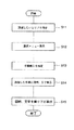
次に、図9乃至図11を参照して、検者自身が前記プログラムに従った検眼手順に新たに手順を追加する場合について説明する。尚、図9は手順を追加する処理の流れを示すフローチャート、図10は手順追加前の表示部10の表示態様、図11は手順追加後の表示部10の表示態様を示すものである。
【0089】
前記表示部10は、自覚式検眼のプログラムに従い、検眼を進める段階に応じて、例えば図10に示すように、レッドグリーンテスト、クロスシリンダーテスト、視力値テスト、両眼バランステスト、加入度テスト等を意味する各視標の図柄を視標表示欄121に各々表示し、これらに対応する検眼結果表示欄131−2乃至131−6は未実行の表示態様(図10では斜線を付して示す)で表示しているものとする。
【0090】
このとき、前記検眼結果表示欄131−2乃至131−6には、各々レッドグリーンテスト、クロスシリンダーテスト、視力値テスト、両眼バランステスト、加入度テストの各文字も併せて表示される。
【0091】
この状態で、検者が例えば両眼バランステストの視標表示欄121及び検眼結果表示欄131−5のエリアを新たに追加したい手順のエリアとして指定すると(ステップS11)、前記表示部10には図11に示すようにメニュー200が重ねて表示される(ステップS12)。
【0092】
次に、検者が前記マウス140を操作してメニュー200のうちの「手順を挿入」を指定し(ステップS13)、更に追加したい手順としてレッドグリーンテストを指定する(ステップS14)。
【0093】
これにより、図11に示すように、追加したい手順であるレッドグリーンテストを示す図柄が視標表示欄121に表示され、レッドグリーンテストの文字が検眼結果表示欄131−5に表示される(ステップS14)。
【0094】
そして、手順追加前において視標表示欄121に表示されていた両眼バランステストの図柄は一段繰り下がって表示され、両眼バランステストの文字も結果表示欄131−6に繰り下がって表示される(ステップS15)。即ち、新たに追加した手順以降の両眼バランステスト、加入度テスト等の手順は各々一段ずつ繰り下がる。
【0095】
手順追加後においても、前記検眼結果表示欄131−2乃至131−6は未実行の表示態様(図11では斜線を付して示す)で表示される。
【0096】
尚、上述したメニュー200としては、図10に示すように、「手順を挿入」の他、「手順をコピー」、「手順を切り取り」、「コピー先に手順を挿入」、「手順を削除」の各項目が表示される。
【0097】
また、図9乃至図11で説明した例では、重複することになるレッドグリーンテストの手順を追加した場合について説明したが、図示しない自覚式検眼に関する種々の手順についても同様に追加できることはいうまでもない。
【0098】
このようにして、検者自身が前記プログラムに従った検眼手順に対して新たに重複した又は別の手順を随時追加することができ、被検眼Eの屈折力等の程度に応じて最適の手順を実行することが可能となる。
【0099】
尚、上述した図9乃至図11では手順の追加を行う場合について説明したが、プログラムに基づいた一連の手順の中から特定の手順を削除する場合についても、上述した場合と同様、削除したいエリアの指定、メニュー200のうちの「手順の削除」の各操作を行うことで同様に実行できる。
【0100】
(実施の形態2)
次に本発明の実施の形態2について説明する。上述した実施の形態1では、プログラム検眼を行う場合に本発明を適用した場合の例を示したが、本発明はこれに限らず、マニュアル検眼、すなわち、検者が視標選択スイッチ43の中から任意のスイッチを適宜選択することにより検眼を進める場合にも適用できる。
【0101】
図12に沿って本実施の形態2について説明する。
【0102】
図12は、マニュアル検眼途中において、実行済みの手順に関する検眼履歴の表示態様を示すものである。
【0103】
前記表示部10は、マニュアル検眼により実行された各種の検査、例えば、図12に示すように、レッドグリーンテスト、クロスシリンダーテスト、視力値テストを意味する各視標の図柄を視標表示欄121に上から順に3段で表示し、かつ、これらに対応する検眼結果表示欄131−2、131−3、131−4には、各々レッドグリーンテスト、クロスシリンダーテスト、視力値テストの検眼結果の数値データを白色の通常表示の表示態様で表示する。
【0104】
また、検眼未実行の4段目、5段目の視標表示欄121及びこれらに対応する検眼結果表示欄131−5、131−6は、例えばグレー表示等による未実行表示(図12では斜線を付して示す)としている。
【0105】
このような前記表示部10における検眼履歴の表示態様により、検者は、自己が一連の検眼手順のうちのいずれの段階までの検眼手順を実行済みかを表示部10を視認するだけで直ちに把握できる。
【0106】
この状態で、検者が前記操作部2の視標選択スイッチ群43の中の両眼バランステスト用のスイッチを押すと、図13に示すように、4段目の視標表示欄121に両眼バランステストを意味する図柄が表示され、また、検眼結果表示欄131−5には両眼バランステストの文字が表示される。そして、検眼結果表示欄131−5は黒の網掛け(クロス斜線で示す)表示に変わる。これと同時に、コントローラCから制御部100を介して視標提示装置80及び検眼ユニット8に命令信号が出力され、これにより、視標提示装置80には両眼バランステスト用のチャートが表示される。
【0107】
【発明の効果】
本発明によれば、以下の効果を奏する。
【0108】
請求項1記載の発明によれば、検者は、自覚式検眼における被検者に提示したた視標と、その検眼段階で検眼結果とを確実に把握でき、再測定の煩雑さを最小限に抑えることができ、検眼の迅速化を図ることができる自覚式検眼装置を提供することができる。
【0109】
また、請求項1記載の発明によれば、検者は、検眼段階で提示される視標を図柄のパターン認識により若しくは視標の名称又は検査の名称により速やかに把握しつつ自覚式検眼を進行することができる自覚式検眼装置を提供することができる。
【0110】
また、請求項1記載の発明によれば、検者は、検眼段階で提示される視標を図柄のパターン認識により又は視標の名称、検査の名称の文字認識により把握しつつ自覚式検眼を進行することができる自覚式検眼装置を提供することができる。
【0111】
請求項4記載の発明によれば、検者は、既に行われた各検眼段階での最終的に決定された検眼結果を把握しつつ後続する自覚式自覚式検眼を進行することができる自覚式検眼装置を提供することができる。
【0112】
請求項2記載の発明によれば、検眼プログラムにより定めた手順により被検者の自覚式検眼を順次実行できる自覚式検眼装置を提供することができる。
【0113】
請求項5記載の発明によれば、検者は、自覚式検眼の進行状況を視覚を通じて明確に区別しつつ被検者の自覚式検眼を実行できる自覚式検眼装置を提供することができる。
【0114】
請求項6記載の発明によれば、検者は、実行済み、実行中、未実行の検査手順を視覚を通じて明確に区別しつつ被検者の自覚式検眼を実行できる自覚式検眼装置を提供することができる。
【0115】
請求項3記載の発明によれば、検者は任意の検眼段階に関する検査手順を再度指定して当該検査手順をやり直す等の選択を行うことができ、検眼結果の疑念が生じた場合等に対応できる自覚式検眼装置を提供することができる。
【0116】
請求項7記載の発明によれば、検者が任意の検眼段階に関する検査手順を再度指定した場合等に視標提示手段及び前記光学素子配置手段をその検査手順に対応する状態にすることができ、検者の指定に応じた検査手順を支障なく実行できる自覚式検眼装置を提供することができる。
【図面の簡単な説明】
【図1】本発明の実施の形態1の自覚式検眼装置を示す正面図である。
【図2】本発明の実施の形態1の自覚式検眼装置におけるコントローラの操作部及び表示部を示す斜視図である。
【図3】本発明の実施の形態1の自覚式検眼装置における操作部を示す平面図である。
【図4】本発明の実施の形態1の自覚式検眼装置における表示部の検眼進行用画面及び検眼履歴表示画面の表示例を示す平面図である。
【図5】本発明の実施の形態1の自覚式検眼装置の検眼ユニットの概略斜視図である。
【図6】本発明の実施の形態1の自覚式検眼装置の制御系を示すブロック図である。
【図7】本発明の実施の形態の検査手順移動前の表示部の表示態様を示す説明図である。
【図8】本発明の実施の形態1の検査手順移動後の表示部の表示態様を示す説明図である。
【図9】本発明の実施の形態1の検査手順を変更する処理の流れを示すフローチャートである。
【図10】本発明の実施の形態1の検査手順変更前の表示部の表示態様を示す説明図である。
【図11】本発明の実施の形態1の検査手順変更後の表示部の表示態様を示す説明図である。
【図12】本発明の実施の形態2の自覚式検眼装置のマニュアル検眼の場合の表示部の検査手順及び検眼結果の表示例を示す説明図である。
【図13】本発明の実施の形態2の自覚式検眼装置のマニュアル検眼の表示部の検査手順の追加例を示す説明図である。
【符号の説明】
1 検眼テーブル
2 操作部
8 検眼ユニット
8a 右眼ユニット
8b 左眼ユニット
8c 検眼窓
8d 検眼窓
10 表示部
10a 表示面
17 ターレット板
43 視標選択スイッチ群
44 ダイヤル
45 送りスイッチ
61 履歴スイッチ
80 視標提示装置
100 制御部
101 プログラムメモリ
110 制御手段
111 ターレット板駆動部
115 RAM
121 視標表示欄
131 検眼結果表示欄
131−2〜131−6 検眼結果表示欄
140 マウス
200 メニュー
E 被検眼
M 被検者
C コントローラ
IP 検眼進行用画面
IH 検眼履歴表示画面[0001]
BACKGROUND OF THE INVENTION
The present invention relates to a subjective optometry apparatus that presents a visual target to a subject and inspects various visual functions of the subject's eye in order based on responses from the subject with respect to the appearance.
[0002]
[Prior art]
In the inspection with the subjective optometry device, the examination of the eye to be examined is started based on the measurement data from the refractometer or lens meter, and the spherical power test, red green test, astigmatic axis test, astigmatism power test, binocular balance test. The optimal corrective refractive power is determined through various types of inspection procedures.
[0003]
In each of such a series of inspection procedures, the inspection is advanced using data in the latest procedure.
[0004]
For this reason, if a mistake occurs in the middle of these various types of inspection procedures, it will affect the subsequent inspection procedures, and errors may occur in the optimum corrected refractive power finally obtained.
[0005]
[Problems to be solved by the invention]
However, the conventional subjective optometry apparatus only outputs measurement data finally obtained through various types of examination procedures.
[0006]
For this reason, even when the examiner has doubts about the final measurement data, it was impossible to know which optometry point had a mistake. As a result, the examiner was forced to redo the measurement through the subjective examination procedure for the subject from the beginning.
[0007]
An object of the present invention is to provide a subjective optometry apparatus capable of minimizing the complexity of re-measurement and thus speeding up optometry in view of the above-described drawbacks of the prior art. To do.
[0008]
[Means for Solving the Problems]
In order to solve the above problems, the present invention is characterized by having the following configuration.
[0009]
According to a first aspect of the present invention, there is provided a subjective optometry apparatus that includes a target presentation means for presenting a target to an eye to be examined and various optical elements, and tests the optical elements according to responses from a subject. Optical element placement means arranged in front of the eye, control means for controlling the target presentation means and the optical element placement means in response to a response from the subject, the target presentation means and / or the optical element placement means Display means for displaying the state of the target, the design or name indicating the target as information on the target presented at each optometry stage, or the name of the test performed from the target, and the target Storage means for associating and storing the optometry results at the stage, and the display means for the design, the name or the name of the examination home Either It is possible to switch the information to be displayed, and any of the information And the optometry result are displayed in association with each other.
[0010]
According to the present invention, when performing subjective optometry of the eye to be examined, the visual target presenting means presents the visual target to the eye to be examined, and the optical element arranging means is subject to the examination based on the control of the control means. An optical element corresponding to the response from the person is placed in front of the eye to be examined. The display means displays the state of the visual target presenting means and / or the optical element arranging means.
[0011]
Further, the storage means stores information relating to the optotype presented at the optometry stage in association with the optometry result at the stage where the optotype is presented.
[0012]
In this way, subjective optometry is performed, and the display means displays the optotype and the optometry result in association with each other.
[0013]
As a result, the examiner can reliably grasp the visual target presented to the subject in each examination in the subjective optometry and the optometry result at the optometry stage, and minimize the complexity of remeasurement. And optometry can be speeded up.
[0014]
Also,
[0015]
Also,
[0016]
According to this invention, since it is possible to switch between the display of the symbol, the name, or the name of the examination, the examiner selects the target presented at the optometry stage by the pattern recognition of the symbol or the name or The subjective optometry can be advanced while grasping by the character recognition of the name of the examination.
[0017]
The invention according to claim 4 is the invention according to
[0018]
According to the present invention, since the optometry result is the optometry result finally determined at each optometry stage, the examiner grasps the optometry result finally determined at each optometry stage. However, the subsequent subjective optometry can be advanced.
[0019]
[0020]
According to the present invention, the registration means registers the optometry program that presents the optotype in a predetermined procedure, and the display means displays the optometry program according to the execution procedure of the optometry program when the optometry program is executed. Thus, the subject's subjective optometry can be sequentially executed according to the procedure determined by the optometry program.
[0021]
[0022]
According to the present invention, the display means visually distinguishes between the inspection procedure that has been executed and the inspection procedure that is being executed or not being executed. Subject's subjective optometry can be executed while clearly distinguishing the progress status visually.
[0023]
[0024]
According to the present invention, the display means visually displays the inspection procedure that has already been executed, the inspection procedure that is being executed, and the inspection procedure that has not been executed. During the execution, the subject's subjective optometry can be executed while clearly distinguishing the unexecuted examination procedure visually.
[0025]
Claim 3 The described invention An optotype presenting means for presenting an optotype to the eye to be examined, an optical element arranging means for holding various optical elements and arranging the optical element in response to a response from the subject, and the subject Control means for controlling the optotype presenting means and the optical element arranging means in response to a response from the display means, display means for displaying the status of the optotype presenting means and / or the optical element arranging means, and at each optometry stage Storage means for associating and storing information on the presented optotype and an optometry result at the stage where the optotype is presented; Designating means for designating any of the displayed optometry stages The display means displays information relating to the visual target in association with the optometry result. It is characterized by this.
[0026]
According to the present invention, since the designation means for designating any one of the displayed optometry stages is provided, the examiner selects the examination procedure relating to the optometry stage again and selects the examination procedure again. It is possible to cope with a case where suspicion of the optometry result occurs.
[0027]
Claim 7 The described invention is claimed. 3 In the subjective optometry apparatus described above, the control means causes the target presentation means and the optical element placement means to reproduce a state corresponding to the designated optometry stage in accordance with a designation operation by the designation means. It is characterized by controlling.
[0028]
According to this invention, the control means controls the optotype presenting means and the optical element arranging means so as to reproduce the state corresponding to the designated optometry stage according to the designation operation by the designation means. Therefore, when the examiner designates the examination procedure relating to an arbitrary optometry stage again, the target presentation means and the optical element arrangement means can be brought into a state corresponding to the examination procedure. The inspection procedure can be executed without any problems.
[0029]
DETAILED DESCRIPTION OF THE INVENTION
Hereinafter, embodiments of the present invention will be described in detail.
[0030]
(Embodiment 1)
The optometry apparatus according to
[0031]
The controller C includes an
[0032]
In addition, the support |
[0033]
The horizontal arm 4 is supported by the
[0034]
Further, an
[0035]
The
[0036]
Further, the right eye unit 8a and the
[0037]
In FIG. 1,
[0038]
A visual
[0039]
As shown in FIG. 5, the
[0040]
FIG. 6 shows a control system of the optometry apparatus according to the first embodiment. The control means 110 includes a
[0041]
The
[0042]
The
[0043]
When one of the optotype
[0044]
The
[0045]
The
[0046]
The
[0047]
The measurement
[0048]
The
[0049]
The examiner changes the icon of the course to be executed to a double line and presses the
[0050]
The item
[0051]
The
[0052]
The
[0053]
FIG. 4 shows an example of a screen displayed on the
[0054]
In the subjective optometry apparatus of the first embodiment, as shown in FIG. 4, the optometry progress screen IP and the optometry history display screen IH are simultaneously displayed on the
[0055]
On the optometry progress screen IP, various data necessary or useful for proceeding with optometry are displayed separately. The optometry history display screen IH displays a plurality of types of tests constituting the optometry program and the progress of optometry at the stage when each test is completed.
[0056]
Normally, the optometry progress screen IP is more active (a state in which it can be operated by keystrokes), but when a part of the optometry history display screen IH (for example, the title bar) is clicked with the
[0057]
To return to the original state, a part of the optometry progress screen IP may be clicked. Both screens can be displayed in parallel from the beginning, and the optometry history display screen IH can be initially closed so that it can be called up as necessary.
[0058]
Next, display contents of the optometry progress screen IP will be described.
[0059]
The
[0060]
Each numerical value changes corresponding to the optical characteristic of the optical member arranged in the optometry windows 8c and 8d. The numerical value is switched stepwise by operating the
[0061]
The reverse display portion is automatically switched depending on the type of the target to be presented, but can also be switched by the
[0062]
The dial
[0063]
The external
[0064]
The
[0065]
The auxiliary optical
[0066]
Next, display contents of the optometry history display screen IH will be described with reference to FIG. On the optometry history display screen IH, there are displayed an
[0067]
The
[0068]
In FIG. 4, only six from the second red-green test target to the sixth addition test target are displayed, but the target before and after that also activates the optometry history display screen IH. It can be displayed by operating the scroll bar SB.
[0069]
The optometry result
[0070]
Here, the name of the examination is the name of the examination executed by the index displayed in the corresponding
[0071]
This will be described along the example shown in FIG. In FIG. 4, a course called “
[0072]
The optometry result display column 131-2 indicates the progress of the test at the stage where the red-green test as the second test is completed (the stage when the
[0073]
Similarly, the optometry result display column 131-3 shows the progress of the examination at the stage when the cross cylinder test, which is the third examination, is completed, and the optometry result display column 131-4 shows the visual acuity value test, which is the fourth examination. It shows the progress of the inspection at the finished stage.
[0074]
Since the binocular balance test is currently being performed and the addition test is performed after the binocular balance test is completed, the columns of the optometry result display columns 131-5 and 131-6 are blank.
[0075]
The fourth and earlier optometry result display columns 131-2, 131-3, and 131-4 are displayed with a white background, so that the examiner knows the progress of the examination and the progress at each stage. Can do.
[0076]
Further, the optometry result display field 131-5 of the binocular balance test being executed is displayed in black shaded (indicated by cross diagonal lines), and no numerical value is displayed.
[0077]
When the binocular balance test is ended by operating the
The optometry result display field 131-6 of the unexecuted addition power test is displayed with gray shading (shown by diagonal lines).
[0078]
The examiner can know the progress of the examination at each examination stage by looking at the optometry
[0079]
Further, when the examiner knows the optometry stage in which the input error is suspected to have occurred by looking at the optometry history display screen IH, the stage in which the input mistake is suspected is not performed again from the beginning. You can redo the optometry.
[0080]
The procedure in this case will be described with reference to FIGS.
[0081]
Here, it is assumed that the examiner has doubts about the optometry result of the third examination, the cross-cylinder test, during the execution of the binocular balance test, which is the fifth examination.
[0082]
First, the examiner uses the
[0083]
Next, the
[0084]
The display on the
[0085]
In other words, after the selection of redoing and before the operation of the
[0086]
If the examiner wishes to cancel the rework of the examination, the examiner moves the pointer of the
[0087]
In this way, the examiner himself can move to the procedure that has been executed at any time while the optometry procedure according to the program is in progress, and can redo the procedure again. It is possible to deal with cases where there is doubt, and to ensure the accuracy of the optometry results of each procedure.
[0088]
Next, the case where the examiner himself adds a new procedure to the optometry procedure according to the program will be described with reference to FIGS. 9 to 11. 9 is a flowchart showing a flow of processing for adding a procedure, FIG. 10 shows a display mode of the
[0089]
The
[0090]
At this time, in the optometry result display columns 131-2 to 131-6, characters of red green test, cross cylinder test, visual acuity value test, binocular balance test, and addition test are also displayed.
[0091]
In this state, when the examiner designates, for example, the areas of the
[0092]
Next, the examiner operates the
[0093]
As a result, as shown in FIG. 11, a symbol indicating the red-green test, which is the procedure to be added, is displayed in the
[0094]
The binocular balance test symbols displayed in the
[0095]
Even after the procedure is added, the optometry result display columns 131-2 to 131-6 are displayed in an unexecuted display mode (shown by hatching in FIG. 11).
[0096]
As shown in FIG. 10, the
[0097]
In the example described with reference to FIGS. 9 to 11, the case where the procedure of the red-green test that overlaps is described. However, it goes without saying that various procedures relating to the subjective optometry which are not shown can be added in the same manner. Nor.
[0098]
In this way, the examiner himself / herself can add a new overlapping or different procedure to the optometry procedure according to the program as needed, and the optimum procedure according to the degree of refractive power of the eye E to be examined. Can be executed.
[0099]
9 to 11 described the case where the procedure is added. However, in the case where a specific procedure is deleted from a series of procedures based on the program, the area to be deleted is the same as the case described above. Can be executed in the same manner by performing each operation of “deletion of procedure” in the
[0100]
(Embodiment 2)
Next, a second embodiment of the present invention will be described. In the first embodiment described above, an example in which the present invention is applied when performing a program optometry is shown. However, the present invention is not limited to this, and the manual optometry, that is, the examiner is in the
[0101]
The second embodiment will be described with reference to FIG.
[0102]
FIG. 12 shows a display form of an optometry history relating to a procedure that has been executed during manual optometry.
[0103]
The
[0104]
In addition, the fourth-stage and fifth-stage
[0105]
By such a display form of the optometry history in the
[0106]
In this state, when the examiner presses the binocular balance test switch in the target
[0107]
【Effect of the invention】
The present invention has the following effects.
[0108]
According to the first aspect of the present invention, the examiner can surely grasp the visual target presented to the subject in the subjective optometry and the optometry result at the optometry stage, thereby minimizing the complexity of remeasurement. It is possible to provide a subjective optometry apparatus that can suppress the optometry and speed up the optometry.
[0109]
Also,
[0110]
Also,
[0111]
According to the invention described in claim 4, the examiner can proceed with the subsequent subjective optometry while grasping the optometry result finally determined at each optometry stage already performed. An optometry apparatus can be provided.
[0112]
[0113]
[0114]
[0115]
Claim 3 According to the described invention, the examiner can select the examination procedure relating to an arbitrary optometry stage again and perform the examination procedure again, and the like, and can respond to a case where suspicion of the optometry result occurs. An optometry apparatus can be provided.
[0116]
Claim 7 According to the described invention, when the examiner designates again an examination procedure relating to an arbitrary optometry stage, the target presentation means and the optical element arranging means can be brought into a state corresponding to the examination procedure. It is possible to provide a subjective optometry apparatus that can execute an examination procedure according to the designation without any trouble.
[Brief description of the drawings]
FIG. 1 is a front view showing a subjective optometry apparatus according to a first embodiment of the present invention.
FIG. 2 is a perspective view showing an operation unit and a display unit of a controller in the subjective optometry apparatus according to the first embodiment of the present invention.
FIG. 3 is a plan view showing an operation unit in the subjective optometry apparatus according to the first embodiment of the present invention.
4 is a plan view showing a display example of an optometry progress screen and an optometry history display screen of a display unit in the subjective optometry apparatus according to the first embodiment of the present invention. FIG.
FIG. 5 is a schematic perspective view of an optometry unit of the subjective optometry apparatus according to the first embodiment of the present invention.
FIG. 6 is a block diagram showing a control system of the subjective optometry apparatus according to the first embodiment of the present invention.
FIG. 7 is an explanatory diagram illustrating a display mode of the display unit before moving the inspection procedure according to the embodiment of this invention.
FIG. 8 is an explanatory diagram showing a display mode of the display unit after moving the inspection procedure according to the first embodiment of the present invention.
FIG. 9 is a flowchart showing a flow of processing for changing the inspection procedure according to the first embodiment of the present invention.
FIG. 10 is an explanatory diagram showing a display mode of the display unit before changing the inspection procedure according to the first embodiment of the present invention.
FIG. 11 is an explanatory diagram showing a display mode of the display unit after changing the inspection procedure according to the first embodiment of the present invention.
FIG. 12 is an explanatory diagram showing a display procedure of the display unit and a display result of the optometry result in the case of manual optometry of the subjective optometry apparatus according to the second embodiment of the present invention.
FIG. 13 is an explanatory diagram showing an additional example of the examination procedure of the display unit of the manual optometry of the subjective optometry apparatus according to the second embodiment of the present invention.
[Explanation of symbols]
1 Optometry table
2 Operation part
8 Optometrist unit
8a Right eye unit
8b Left eye unit
8c optometry window
8d optometry window
10 Display section
10a Display surface
17 Turret plate
43 Target selection switch group
44 dial
45 Feed switch
61 History switch
80 Target presentation device
100 Control unit
101 Program memory
110 Control means
111 Turret plate drive
115 RAM
121 Target display column
131 Optometry result display field
131-2 to 131-6 Optometry result display field
140 mice
200 menu
E Eye to be examined
M Subject
C controller
IP optometry progress screen
IH optometry history display screen
Claims (7)
各種の光学素子を保持し、被検者からの応答に応じた該光学素子を被検眼前に配置する光学素子配置手段と、
被検者からの応答に応じて前記視標提示手段と前記光学素子配置手段を制御する制御手段と、
前記視標提示手段及び/又は前記光学素子配置手段の状態を表示する表示手段と、
各検眼段階で提示される視標に関する情報としてのその視標を示す図柄若しくは名称又はその視標より実行される検査の名称と、その視標が提示された段階での検眼結果とを関連付けて記憶する記憶手段とを備え、
前記表示手段は、前記図柄、前記名称又は前記検査の名称のうちいずれの情報を表示するかを切替可能とし、当該いずれかの情報と該検眼結果とを関連付けて表示することを特徴とする自覚式検眼装置。A target presentation means for presenting a target to the eye to be examined;
Optical element placement means for holding various optical elements and placing the optical elements according to the response from the subject before the eye to be examined;
Control means for controlling the optotype presenting means and the optical element arranging means in response to a response from a subject;
Display means for displaying the state of the target presentation means and / or the optical element placement means;
Associating the design or name indicating the target as information on the target presented at each optometry stage, or the name of the examination performed from the target and the optometry result at the stage where the target is presented Storage means for storing,
Subjective said display means, said pattern, and whether a possible switch to display any information of the name or names of the test, and displaying in association with the one of the information and該検eye results Type optometry device.
各種の光学素子を保持し、被検者からの応答に応じた該光学素子を被検眼前に配置する光学素子配置手段と、
被検者からの応答に応じて前記視標提示手段と前記光学素子配置手段を制御する制御手段と、
前記視標提示手段及び/又は前記光学素子配置手段の状態を表示する表示手段と、
各検眼段階で提示される視標に関する情報とその視標が提示された段階での検眼結果とを関連付けて記憶する記憶手段と、
所定の手順で視標を提示する検眼プログラムを登録する登録手段とを備え、
前記表示手段は、該検眼プログラムが実行される際、該検眼プログラムの実行手順に沿って、前記視標に関する情報と該検眼結果とを関連付けて表示することを特徴とする自覚式検眼装置。A target presentation means for presenting a target to the eye to be examined;
Optical element placement means for holding various optical elements and placing the optical elements according to the response from the subject before the eye to be examined;
Control means for controlling the optotype presenting means and the optical element arranging means in response to a response from a subject;
Display means for displaying the state of the target presentation means and / or the optical element placement means;
Storage means for storing information relating to the optotype presented at each optometry stage in association with the optometry result at the stage where the optotype was presented;
Registration means for registering an optometry program that presents the optotype in a predetermined procedure,
When the optometry program is executed, the display means displays information relating to the visual target and the optometry result in association with an execution procedure of the optometry program, and is a subjective optometry apparatus.
各種の光学素子を保持し、被検者からの応答に応じた該光学素子を被検眼前に配置する光学素子配置手段と、
被検者からの応答に応じて前記視標提示手段と前記光学素子配置手段を制御する制御手段と、
前記視標提示手段及び/又は前記光学素子配置手段の状態を表示する表示手段と、
各検眼段階で提示される視標に関する情報とその視標が提示された段階での検眼結果とを関連付けて記憶する記憶手段と、
表示された検眼段階のうち任意のものを指定する指定手段とを備え、
前記表示手段は、前記視標に関する情報と該検眼結果とを関連付けて表示することを特徴とする自覚式検眼装置。A target presentation means for presenting a target to the eye to be examined;
Optical element placement means for holding various optical elements and placing the optical elements according to the response from the subject before the eye to be examined;
Control means for controlling the optotype presenting means and the optical element arranging means in response to a response from a subject;
Display means for displaying the state of the target presentation means and / or the optical element placement means;
Storage means for storing information relating to the optotype presented at each optometry stage in association with the optometry result at the stage where the optotype was presented;
Specifying means for specifying any of the displayed optometry stages,
The said display means displays the information regarding the said optotype and this optometry result in association with each other, and is a subjective optometry apparatus,
Priority Applications (1)
| Application Number | Priority Date | Filing Date | Title |
|---|---|---|---|
| JP2001054378A JP4884590B2 (en) | 2001-02-28 | 2001-02-28 | A subjective optometry device |
Applications Claiming Priority (1)
| Application Number | Priority Date | Filing Date | Title |
|---|---|---|---|
| JP2001054378A JP4884590B2 (en) | 2001-02-28 | 2001-02-28 | A subjective optometry device |
Publications (2)
| Publication Number | Publication Date |
|---|---|
| JP2002253503A JP2002253503A (en) | 2002-09-10 |
| JP4884590B2 true JP4884590B2 (en) | 2012-02-29 |
Family
ID=18914720
Family Applications (1)
| Application Number | Title | Priority Date | Filing Date |
|---|---|---|---|
| JP2001054378A Expired - Lifetime JP4884590B2 (en) | 2001-02-28 | 2001-02-28 | A subjective optometry device |
Country Status (1)
| Country | Link |
|---|---|
| JP (1) | JP4884590B2 (en) |
Families Citing this family (11)
| Publication number | Priority date | Publication date | Assignee | Title |
|---|---|---|---|---|
| JP4498806B2 (en) * | 2004-04-06 | 2010-07-07 | 株式会社トプコン | Inspection information input support system and inspection information input support program |
| JP4535867B2 (en) | 2004-12-28 | 2010-09-01 | 株式会社トプコン | Optometry equipment |
| JP4749836B2 (en) * | 2005-11-04 | 2011-08-17 | 株式会社ニデック | Ophthalmic equipment |
| JP4920282B2 (en) * | 2006-03-30 | 2012-04-18 | 株式会社トプコン | A subjective optometry device |
| JP4916753B2 (en) * | 2006-03-31 | 2012-04-18 | 株式会社トプコン | A subjective optometry device |
| JP4791232B2 (en) * | 2006-04-10 | 2011-10-12 | 株式会社トプコン | A subjective optometry device |
| JP4976042B2 (en) * | 2006-04-11 | 2012-07-18 | 株式会社トプコン | A subjective optometry device |
| JP4989215B2 (en) * | 2006-12-26 | 2012-08-01 | 株式会社トプコン | A subjective optometry device |
| JP6168514B2 (en) * | 2013-05-21 | 2017-07-26 | 東海光学株式会社 | Refractive power measurement method in the dark |
| JP6753123B2 (en) * | 2016-04-12 | 2020-09-09 | 株式会社ニデック | Controller for subjective optometry device and subjective optometry device |
| WO2023203992A1 (en) * | 2022-04-19 | 2023-10-26 | キヤノン株式会社 | Information processing device, method for controlling information processing device, and program |
Family Cites Families (4)
| Publication number | Priority date | Publication date | Assignee | Title |
|---|---|---|---|---|
| JPS5596773A (en) * | 1979-01-19 | 1980-07-23 | Hitachi Ltd | Discrimination unit |
| JP2846633B2 (en) * | 1987-09-10 | 1999-01-13 | 株式会社ニデック | Refractive power inspection device |
| JPH0690902A (en) * | 1992-09-16 | 1994-04-05 | Canon Inc | Ophthalmic refractometer |
| JPH07194539A (en) * | 1993-12-30 | 1995-08-01 | Topcon Corp | Optometric device |
-
2001
- 2001-02-28 JP JP2001054378A patent/JP4884590B2/en not_active Expired - Lifetime
Also Published As
| Publication number | Publication date |
|---|---|
| JP2002253503A (en) | 2002-09-10 |
Similar Documents
| Publication | Publication Date | Title |
|---|---|---|
| JP6206430B2 (en) | Ophthalmic device control method | |
| JP4884590B2 (en) | A subjective optometry device | |
| JP3330968B2 (en) | Subjective optometry device | |
| JP5701494B2 (en) | Fundus image processing apparatus and fundus image processing method | |
| JP4629853B2 (en) | A subjective optometry device | |
| KR101521653B1 (en) | Optometric apparatus | |
| US7537342B2 (en) | Subjective optometric apparatus | |
| US5627612A (en) | Ophthalmic apparatus having program storing means | |
| JP3504381B2 (en) | Optometrist | |
| JP5016348B2 (en) | A subjective optometry device | |
| JP2002209850A (en) | Ophthalmometer | |
| JP2009005903A (en) | Eye target presentation device, optometric apparatus, and eye test method using optometric apparatus | |
| JP3953557B2 (en) | Optometry equipment | |
| JP2002224034A (en) | Subjective optometrical device | |
| JP2022079772A (en) | Optometric apparatus, method, and program | |
| JPH08308799A (en) | Optometric apparatus | |
| JP2020146284A (en) | Optotype display device and optotype display control method thereof | |
| JP3660076B2 (en) | Optometry equipment | |
| JPH07194539A (en) | Optometric device | |
| JP4989215B2 (en) | A subjective optometry device | |
| JP2002034917A (en) | Optometry apparatus | |
| JP6685351B2 (en) | Aware optometry device, operating device and program | |
| JPH10328138A (en) | Optometric device and optometry system | |
| JP4791232B2 (en) | A subjective optometry device | |
| JP3623323B2 (en) | Optometry equipment |
Legal Events
| Date | Code | Title | Description |
|---|---|---|---|
| A621 | Written request for application examination |
Free format text: JAPANESE INTERMEDIATE CODE: A621 Effective date: 20080206 |
|
| RD02 | Notification of acceptance of power of attorney |
Free format text: JAPANESE INTERMEDIATE CODE: A7422 Effective date: 20081217 |
|
| A977 | Report on retrieval |
Free format text: JAPANESE INTERMEDIATE CODE: A971007 Effective date: 20101213 |
|
| A131 | Notification of reasons for refusal |
Free format text: JAPANESE INTERMEDIATE CODE: A131 Effective date: 20101221 |
|
| A521 | Written amendment |
Free format text: JAPANESE INTERMEDIATE CODE: A523 Effective date: 20110216 |
|
| A131 | Notification of reasons for refusal |
Free format text: JAPANESE INTERMEDIATE CODE: A131 Effective date: 20110524 |
|
| A521 | Written amendment |
Free format text: JAPANESE INTERMEDIATE CODE: A523 Effective date: 20110721 |
|
| TRDD | Decision of grant or rejection written | ||
| A01 | Written decision to grant a patent or to grant a registration (utility model) |
Free format text: JAPANESE INTERMEDIATE CODE: A01 Effective date: 20111206 |
|
| A01 | Written decision to grant a patent or to grant a registration (utility model) |
Free format text: JAPANESE INTERMEDIATE CODE: A01 |
|
| A61 | First payment of annual fees (during grant procedure) |
Free format text: JAPANESE INTERMEDIATE CODE: A61 Effective date: 20111207 |
|
| FPAY | Renewal fee payment (event date is renewal date of database) |
Free format text: PAYMENT UNTIL: 20141216 Year of fee payment: 3 |
|
| R150 | Certificate of patent or registration of utility model |
Ref document number: 4884590 Country of ref document: JP Free format text: JAPANESE INTERMEDIATE CODE: R150 Free format text: JAPANESE INTERMEDIATE CODE: R150 |
|
| R250 | Receipt of annual fees |
Free format text: JAPANESE INTERMEDIATE CODE: R250 |
|
| R250 | Receipt of annual fees |
Free format text: JAPANESE INTERMEDIATE CODE: R250 |
|
| R250 | Receipt of annual fees |
Free format text: JAPANESE INTERMEDIATE CODE: R250 |
|
| R250 | Receipt of annual fees |
Free format text: JAPANESE INTERMEDIATE CODE: R250 |
|
| R250 | Receipt of annual fees |
Free format text: JAPANESE INTERMEDIATE CODE: R250 |
|
| R250 | Receipt of annual fees |
Free format text: JAPANESE INTERMEDIATE CODE: R250 |
|
| R250 | Receipt of annual fees |
Free format text: JAPANESE INTERMEDIATE CODE: R250 |
|
| EXPY | Cancellation because of completion of term |