JP4882863B2 - Hanging device - Google Patents
Hanging device Download PDFInfo
- Publication number
- JP4882863B2 JP4882863B2 JP2007132877A JP2007132877A JP4882863B2 JP 4882863 B2 JP4882863 B2 JP 4882863B2 JP 2007132877 A JP2007132877 A JP 2007132877A JP 2007132877 A JP2007132877 A JP 2007132877A JP 4882863 B2 JP4882863 B2 JP 4882863B2
- Authority
- JP
- Japan
- Prior art keywords
- cord
- winding
- plug
- connecting member
- groove
- Prior art date
- Legal status (The legal status is an assumption and is not a legal conclusion. Google has not performed a legal analysis and makes no representation as to the accuracy of the status listed.)
- Expired - Fee Related
Links
Images


Classifications
-
- A—HUMAN NECESSITIES
- A45—HAND OR TRAVELLING ARTICLES
- A45F—TRAVELLING OR CAMP EQUIPMENT: SACKS OR PACKS CARRIED ON THE BODY
- A45F5/00—Holders or carriers for hand articles; Holders or carriers for use while travelling or camping
- A45F5/004—Holders or carriers for hand articles; Holders or carriers for use while travelling or camping with an automatic spring reel
-
- H—ELECTRICITY
- H04—ELECTRIC COMMUNICATION TECHNIQUE
- H04R—LOUDSPEAKERS, MICROPHONES, GRAMOPHONE PICK-UPS OR LIKE ACOUSTIC ELECTROMECHANICAL TRANSDUCERS; DEAF-AID SETS; PUBLIC ADDRESS SYSTEMS
- H04R1/00—Details of transducers, loudspeakers or microphones
- H04R1/10—Earpieces; Attachments therefor ; Earphones; Monophonic headphones
- H04R1/1033—Cables or cables storage, e.g. cable reels
-
- A—HUMAN NECESSITIES
- A45—HAND OR TRAVELLING ARTICLES
- A45F—TRAVELLING OR CAMP EQUIPMENT: SACKS OR PACKS CARRIED ON THE BODY
- A45F5/00—Holders or carriers for hand articles; Holders or carriers for use while travelling or camping
- A45F2005/006—Holders or carriers for hand articles; Holders or carriers for use while travelling or camping comprising a suspension strap or lanyard
-
- A—HUMAN NECESSITIES
- A45—HAND OR TRAVELLING ARTICLES
- A45F—TRAVELLING OR CAMP EQUIPMENT: SACKS OR PACKS CARRIED ON THE BODY
- A45F2200/00—Details not otherwise provided for in A45F
- A45F2200/05—Holder or carrier for specific articles
- A45F2200/0516—Portable handheld communication devices, e.g. mobile phone, pager, beeper, PDA, smart phone
-
- A—HUMAN NECESSITIES
- A45—HAND OR TRAVELLING ARTICLES
- A45F—TRAVELLING OR CAMP EQUIPMENT: SACKS OR PACKS CARRIED ON THE BODY
- A45F5/00—Holders or carriers for hand articles; Holders or carriers for use while travelling or camping
-
- H—ELECTRICITY
- H04—ELECTRIC COMMUNICATION TECHNIQUE
- H04R—LOUDSPEAKERS, MICROPHONES, GRAMOPHONE PICK-UPS OR LIKE ACOUSTIC ELECTROMECHANICAL TRANSDUCERS; DEAF-AID SETS; PUBLIC ADDRESS SYSTEMS
- H04R1/00—Details of transducers, loudspeakers or microphones
- H04R1/10—Earpieces; Attachments therefor ; Earphones; Monophonic headphones
- H04R1/1016—Earpieces of the intra-aural type
-
- H—ELECTRICITY
- H04—ELECTRIC COMMUNICATION TECHNIQUE
- H04R—LOUDSPEAKERS, MICROPHONES, GRAMOPHONE PICK-UPS OR LIKE ACOUSTIC ELECTROMECHANICAL TRANSDUCERS; DEAF-AID SETS; PUBLIC ADDRESS SYSTEMS
- H04R1/00—Details of transducers, loudspeakers or microphones
- H04R1/10—Earpieces; Attachments therefor ; Earphones; Monophonic headphones
- H04R1/1041—Mechanical or electronic switches, or control elements
-
- H—ELECTRICITY
- H04—ELECTRIC COMMUNICATION TECHNIQUE
- H04R—LOUDSPEAKERS, MICROPHONES, GRAMOPHONE PICK-UPS OR LIKE ACOUSTIC ELECTROMECHANICAL TRANSDUCERS; DEAF-AID SETS; PUBLIC ADDRESS SYSTEMS
- H04R5/00—Stereophonic arrangements
- H04R5/033—Headphones for stereophonic communication
Description
本発明は吊下げ装置に係り、とくにコードが接続される電子機器を吊下げる吊下げ装置に関する。 The present invention relates to a hoisting equipment, about the suspended equipment, especially hanging the electronic device in which the code is connected.
携帯電話機の技術の進歩に伴って、各種の機能が取付けられるようになっている。すなわち携帯電話機に、デジタルカメラやミュージックプレーヤ等の機能のみならず、ワンセグテレビと称されるテレビジョン放送の受像機としての機能や、Suica(登録商標)やFelica(登録商標)等のような決済機能等の様々な付加機能が追加される傾向にある。これによって音楽の再生プレーヤを首からネックストラップによって吊下げ、また胸のポケットや鞄の中に入れて使用し、さらにその他に財布や定期券を持って行動する行動様式に代えて、携帯電話機をネックストラップによって首から吊下げて、テレビジョン放送の視聴や電車での移動、あるいは買い物等を行なうことが可能になっている。 With the advancement of mobile phone technology, various functions can be attached. That is, not only functions such as digital cameras and music players, but also functions as a television broadcast receiver called one-segment television, payment such as Suica (registered trademark), Felica (registered trademark), etc. Various additional functions such as functions tend to be added. This allows the music player to be hung from the neck with a neck strap, placed in a chest pocket or bag, and used as a mobile phone instead of acting with a wallet or commuter pass. It can be hung from the neck with a neck strap to watch television broadcasts, move by train, or shop.
一方で、電源や音声信号を伝達するためのコードが付いた電子機器において、コードを巻取るための巻取り装置を設けることは、例えば特公平5−34840号公報や、実開昭57−91389号公報に開示されているように、従来から広く行なわれている。ヘッドホンやヘッドセットにおいても、収納時におけるコードの絡みを防止することを目的として、コードを巻取る巻取り機構を用いることは、とくに珍しくなくなっている。このような状況下において、携帯電話機の多機能化や、数百、数千の曲や映像を再生する携帯式デジタルプレーヤ等のような携帯式電子機器の進化によって、より便利な携帯性能を考慮した使用方法が求められる傾向にある。 On the other hand, it is possible to provide a winding device for winding a cord in an electronic device with a cord for transmitting a power source or an audio signal, for example, Japanese Patent Publication No. 5-34840 or Japanese Utility Model Publication No. 57-91389. As disclosed in the Gazette, it has been widely performed conventionally. Even in headphones and headsets, the use of a winding mechanism for winding a cord for the purpose of preventing the cord from being entangled at the time of storage is not uncommon. Under such circumstances, more convenient portable performance is considered by the development of portable electronic devices such as a portable digital player that reproduces hundreds or thousands of songs and videos, etc. There is a tendency to require the use method.
しかるに、とくに多機能化する携帯電話機に対し、便利なストラップ式のヘッドホン、ヘッドセットは、存在しなかった。何故ならば、従来の小型プレーヤをネックストラップによって首から吊下げるタイプのものであって、ワンセグのテレビジョン受像機の機能や、決済機能を有する携帯電話機を首に吊下げて使用する場合には、ネックストラップから携帯電話機までの吊下げ長さが首から胸までで一定の値になる。従ってそのままの状態で、携帯電話機によってワンセグ機能を利用してテレビジョン受像機を視聴しようとすると、胸からの距離が20cm程度の値になってしまい、ディスプレイの位置が近すぎる位置になる。このことから、携帯電話機によってテレビジョン受像機を視聴する場合には、ネックストラップを取外す必要があった。また自動改札機も腰の高さ程度の位置に自動改札機のタッチセンサがあるために、ネックストラップによって首から吊下げた携帯電話機を自動改札機のタッチセンサにかざすためには不自然な姿勢をとらなければならず、このために、いちいち携帯電話機を首から取外して携帯電話機を自動改札機のタッチセンサにアクセスする必要があった。 However, there are no convenient strap-type headphones or headsets for mobile phones that are especially multifunctional. This is because when a conventional small player is of a type that is suspended from the neck by a neck strap, and a mobile phone having a one-segment television receiver function or a settlement function is suspended from the neck. The hanging length from the neck strap to the mobile phone is a constant value from the neck to the chest. Therefore, if an attempt is made to watch a television receiver using the one-segment function with a mobile phone in the state as it is, the distance from the chest becomes a value of about 20 cm, and the position of the display becomes too close. For this reason, it is necessary to remove the neck strap when viewing the television receiver with a mobile phone. The automatic ticket gate also has an automatic ticket gate touch sensor at a waist level, so it is unnatural to hold a mobile phone suspended from the neck by a neck strap over the automatic ticket gate touch sensor. Therefore, it was necessary to remove the cellular phone from the neck and access the cellular phone to the touch sensor of the automatic ticket gate.
また巻取り装置によって巻取られるコードは、最大引出し長さを想定して全長が定められる。ところが実際には、使用する態様や、使用するユーザの好み等に応じて、使用されるコードの長さが変化する。従って、最大長さに設定された場合には、多かれ少なかれ、コードが余剰部分を生ずる。従ってこのような余剰部分は、何等かの巻取り手段によって巻取っておかないと、コードが他の部位に引掛かったり、扱いが面倒になったりする問題がある。
本願発明の課題は、首に巻付けられているネックストラップによって吊下げられるとともに、コードが巻取り装置によって巻取り可能であって、しかも使用位置が任意に調整可能な携帯式電子機器の吊下げ装置を提供することである。 An object of the present invention is to suspend a portable electronic device that is suspended by a neck strap wound around a neck, and a cord can be wound by a winding device, and the use position can be arbitrarily adjusted. Is to provide a device.
本願発明の別の課題は、電子機器の荷重がコードにかからないようにした吊下げ装置を提供することである。 Another object of the present invention is to provide a suspension device in which the load of the electronic device is not applied to the cord.
本願発明のさらに別の課題は、重量が重い電子機器であっても、巻取り装置から引出されてずり落ちることがないようにした吊下げ装置を提供することである。 Still another object of the present invention is to provide a suspending device that prevents a heavy electronic device from being pulled out and pulled out of a winding device.
本願発明のさらに別の課題は、コードの長さを任意に調整可能にし、これによって首から吊下げたままでテレビ放送の視聴を可能にした吊下げ装置を提供することである。 Still another object of the present invention is to provide a suspension device that allows the length of a cord to be arbitrarily adjusted, thereby enabling viewing of a television broadcast while being suspended from the neck.
本願発明のさらに別の課題は、携帯情報端末を吊下げたままの状態で、しかも自動改札機のタッチセンサにアクセス可能な吊下げ装置を提供することである。 Still another object of the present invention is to provide a suspension device that can access a touch sensor of an automatic ticket gate while the portable information terminal is suspended.
本願発明の上記の課題および別の課題は、以下に述べる本願発明の技術的思想およびその実施の形態によって明らかにされる。 The above-described problems and other problems of the present invention will be clarified by the technical idea of the present invention and the embodiments thereof described below.
本願の主要な発明は、コードを巻取るリールを有し、該リールの回転によって電子機器または電子部品に接続された前記コードを筐体の口部から引出すとともに、前記口部を通して巻取るようにした巻取り部と、
前記巻取り部の口部の近傍に設けられた係合部と、
前記コードに取付けられており、前記口部の係合部と係合および解除可能な連結部材と、
を備え、
前記コードは、前記連結部材内を挿通されるとともに前記連結部材の側部から引き出され、該引き出されたコードの先端にプラグを有し、前記プラグを介して前記電子機器又は電子部品に接続され、
前記連結部材には吊下げ紐が取り付けられ、前記吊下げ紐を介して前記電子機器又は電子部品が吊下げられ、
前記係合部は、前記連結部材と係合および解除する方向に対して垂直な方向に溝を有し、
前記連結部材は、前記溝に対して前記垂直な方向から係合および離間するクリップ部を有し、該クリップ部が前記溝に係合および離間することにより前記係合部との係合および解除が行われる
吊下げ装置に関するものである。
A main invention of the present application has a reel for winding a cord, and the cord connected to the electronic device or the electronic component is pulled out from the mouth portion of the housing by the rotation of the reel, and is wound through the mouth portion. Winding part,
An engaging portion provided in the vicinity of the mouth of the winding portion;
A connecting member attached to the cord and capable of engaging and releasing with an engaging portion of the mouth;
With
The cord is inserted through the coupling member and pulled out from a side portion of the coupling member. The cord has a plug at the leading end of the drawn cord, and is connected to the electronic device or electronic component through the plug. ,
A hanging string is attached to the connecting member, and the electronic device or electronic component is suspended through the hanging string ,
The engagement portion has a groove in a direction perpendicular to a direction in which the engagement member is engaged and released.
The connecting member has a clip portion that engages and separates from the direction perpendicular to the groove, and the clip portion engages and separates from the groove when the clip portion engages and separates from the groove. The present invention relates to a hanging device in which
ここで、前記プラグの内部に、マイクロホンを有してよい。また前記プラグには、操作釦が取り付けられてよい。また前記巻取り部は、前記コードの引出し長さが0〜0.6mの範囲内であってよい。 Here, in the interior of the previous Symbol plug, it may have a microphone. An operation button may be attached to the plug. Further, the winding portion may have a cord drawing length of 0 to 0.6 m.
またここで、前記リールはロック手段を有し、該ロック手段によってリールのロックが行なわれると前記コードの巻取りができなくなり、ロック状態において前記コードを引出すと前記ロック手段によるロックが解除されるようにしてよい。 Further, the reel has a locking means, and when the reel is locked by the locking means, the cord cannot be wound, and when the cord is pulled out in the locked state, the locking by the locking means is released. You may do it.
また、前記コードに取り付けられ、前記プラグと前記連結部材との間の所定の位置に配置される第2の巻取り部と、
をさらに有し、
前記第2の巻取り部は、前記コードの余分な長さの部分を巻き取るようにしてよい。
A second winding portion attached to the cord and disposed at a predetermined position between the plug and the connecting member ;
Further comprising
The second winding unit may wind up an extra length of the cord.
本願発明の好ましい態様は、ネックストラップタイプのヘッドホン・ヘッドセットの吊下げ装置において、プラグ付きコードをぜんまいばね付きのリールで巻取るようにし、携帯電話機と連結された連結部材を備え、この連結部材にコードの引出しを防止する係合機構を設けるようにしたものである。ここで、コードの引出し長さを0〜0.6mの範囲内で調整可能にしている。またコードの引出し長さの固定手段を、コードをさらに引出すことによって解除することを可能にしている。また連結部材に携帯電話機を吊下げる吊下げ紐の長さを調整可能にしている。またコードの先端側のプラグにマイクロホンと着信スイッチとを設けるようにしている。またコードの余分な長さの部分を連結部材に収納可能にするか、あるいは巻取り手段を設けるか、若しくはカールコードにする。 A preferred embodiment of the present invention is a hanging device for a neck strap type headphone / headset, wherein a cord with a plug is wound up by a reel with a mainspring spring, and a coupling member coupled to a mobile phone is provided. An engagement mechanism for preventing the cord from being pulled out is provided. Here, the lead length of the cord can be adjusted within a range of 0 to 0.6 m. Further, the cord drawing length fixing means can be released by further drawing the cord. In addition, the length of the hanging strap that suspends the mobile phone from the connecting member can be adjusted. Also, a microphone and an incoming call switch are provided on the plug on the tip side of the cord. Further, the extra length of the cord can be accommodated in the connecting member, a winding means is provided, or a curled cord is used.
このような態様によると、コードをぜんまいばね付きのリールで巻取るストラップ装着方式のヘッドホン・ヘッドセットにおいて、連結部材に係合機構を設けることによって、重量がある携帯電話機でも、その重さに関係なくずり下がることがなく、しかもコードを引出す際にも軽快でしかも巻取り力をも強すぎずに設定することが可能になる。また携帯電話機を巻取り可能なコードに連結したことによって、コードの長さを調整できるために、携帯電話機のワンセグ機能を利用して、テレビ放送を視聴する際に、ネックストラップによって首から吊下げたままの状態で、視聴することができる。また自動改札機を通過する際に、ネックストラップによって首から下げた携帯電話機をタッチセンサに容易にアクセスさせることができ、このためにいちいちネックストラップを首から外す必要がなくなる。またヘッドセットに構成する場合には、プラグの内部にマイクロホンを配置することによって、マイクロホン用のシールド線をマイク内部で完結することができ、巻取りコード部はオーディオ信号だけで済むようになり、線材構成が簡単で、コードも細くできる。また巻取り部分の小型軽量化とコード断線防止による耐久性の向上が可能になる。また接続用プラグ付きコードの余剰な長さを糸巻きに巻いたり、カールコードにしたりすることによって、余分なコードが外にはみ出すことがなくなる。 According to such an aspect, in the headphone / headset of the strap mounting method in which the cord is wound with the reel having the mainspring spring, the connection member is provided with the engagement mechanism, so that even the heavy mobile phone is related to the weight. There is no slipping down, and it is possible to set the cord without pulling out the cord without pulling out the cord. In addition, since the length of the cord can be adjusted by connecting the cellular phone to a windable cord, it is suspended from the neck strap with a neck strap when watching TV broadcasting using the one-segment function of the cellular phone. You can watch it as it is. Further, when passing through the automatic ticket gate, the mobile phone lowered from the neck by the neck strap can be easily accessed by the touch sensor, and therefore, it is not necessary to remove the neck strap from the neck every time. In addition, when configuring the headset, by placing the microphone inside the plug, the shield wire for the microphone can be completed inside the microphone, and the winding cord portion can be only an audio signal, The wire composition is simple and the cord can be made thin. In addition, it is possible to improve durability by reducing the size and weight of the winding portion and preventing the cord from being disconnected. Further, by winding the extra length of the cord with the connecting plug around a spool or by using a curled cord, the extra cord is prevented from protruding outside.
本願の主要な発明は、コードを巻取るリールを有し、該リールの回転によって電子機器または電子部品に接続された前記コードを筐体の口部から引出すとともに、前記口部を通して巻取るようにした巻取り部と、前記巻取り部の口部の近傍に設けられた係合部と、前記コードに取付けられており、前記口部の係合部と係合および解除可能な連結部材と、を備え、前記コードは、前記連結部材内を挿通されるとともに前記連結部材の側部から引き出され、該引き出されたコードの先端にプラグを有し、前記プラグを介して前記電子機器又は電子部品に接続され、前記連結部材には吊下げ紐が取り付けられ、前記吊下げ紐を介して前記電子機器又は電子部品が吊下げられ、係合部は連結部材と係合および解除する方向に対して垂直な方向に溝を有し、連結部材は、溝に対して垂直な方向から係合および離間するクリップ部を有し、該クリップ部が溝に係合および離間することにより係合部との係合および解除が行われるようにしたものである。 A main invention of the present application has a reel for winding a cord, and the cord connected to the electronic device or the electronic component is pulled out from the mouth portion of the housing by the rotation of the reel, and is wound through the mouth portion. A winding member, an engaging portion provided in the vicinity of the mouth portion of the winding portion, a connecting member that is attached to the cord and can be engaged with and released from the engaging portion of the mouth portion, The cord is inserted through the connecting member and pulled out from a side portion of the connecting member, and has a plug at the leading end of the drawn cord, and the electronic device or electronic component is inserted through the plug. A suspension string is attached to the coupling member, the electronic device or electronic component is suspended via the suspension string , and the engaging portion is engaged with and released from the coupling member. Has a groove in the vertical direction , Connecting member has a clip portion which engages and separates from a direction perpendicular to the grooves, so that the engagement and release of the engaging portion is performed by the clip portion engages and spaced grooves It is a thing.
従ってこのような吊下げ装置によると、連結部材を巻取り部から離脱させるとともに、電子機器又は電子部品を手で任意の位置に移動させる際に、この電子機器又は電子部品に接続されているコードが巻取り部から引出されるようになり、これによって任意の位置で電子機器又は電子部品を使用することが可能になる。 Therefore, according to such a suspension device, with disengaging the coupling member from the winding unit, when moving to an arbitrary position by hand electronic devices or electronic components, it is connected to the child device or electronic component electrostatic this and has the code is to be pulled out from the winding unit, thereby it is possible to use the child devices or electronic components conductive at any position.
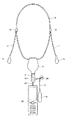
以下本願発明を図示の実施の形態によって説明する。図1は本実施の形態の携帯電話機の吊下げ装置の全体の構成を示しており、この吊下げ装置はネックストラップ10を備えている。ネックストラップ10は首に巻付けることによって、携帯電話機20を吊下げて保持するようになっている。そしてネックストラップ10にはその長さ方向に沿ってコード11が配索されるとともに、押え14の位置でこのコード11がネックストラップ10から分離されるようになっている。そしてコード11の先端にはイヤホン12あるいはヘッドホンが接続される。イヤホン12は、携帯電話機20をミュージックプレーヤとして使用する場合の再生装置として機能する。あるいはまた携帯電話機20によってハンズフリーで用いるときの受話器としてイヤホン12が用いられる。
The present invention will be described below with reference to embodiments shown in the drawings. FIG. 1 shows the overall configuration of a hanging device for a mobile phone according to the present embodiment, and this hanging device includes a
上記ネックストラップ10のペンダントに当たる部位に、巻取り装置13が取付けられる。この巻取り装置13の下端側の筒状口部15に連結部材16が接続されるとともに、この連結部材16の側方からコード17が引出され、このコード17の先端部にプラグ18が接続されている。プラグ18は、携帯電話機20の側面側のジャックに挿入されるようになっている。そして携帯電話機20は、上記連結部材16に、吊下げ紐21を介して吊下げられるようになっている。
A winding
この携帯電話機20の吊下げ方式の特徴は、携帯電話機20の荷重を、巻取り装置13、連結部材16、および吊下げ紐21を介してネックストラップ10によって吊下げるものである。ここで巻取り装置13によって引出しおよび巻取り自在になっているコード17には、携帯電話機20の荷重がかからないようになっている。これは連結部材16に係合機構が設けられ、この係合機構によって、連結部材16が巻取り装置13の筐体の筒状口部15に係合保持される構造を採用しているからである。
A feature of the hanging system of the
巻取り装置13の筒状口部15と連結部材16との係合を解除すると、図2に示すように、連結部材16が筒状口部15から離脱する。従って携帯電話機20を手で持って、巻取り装置13から離れるように移動させると、この携帯電話機20に接続されているプラグ18が接続されているコード17が、巻取り装置13の筒状口部15から引出されるようになる。従ってこの巻取り装置13に巻取られているコード17の最大長まで任意に引出して携帯電話機20を任意の位置に移動させることができる。従って、例えば自動改札機のタッチセンサにアクセスさせる場合においても、連結部材16を筒状口部15から離脱させて携帯電話機20を自動改札機のタッチセンサの上に容易にかざすことができる。
When the engagement between the
図3は巻取り装置13および連結部材16の構成を示している。巻取り装置13はシャーシ25を備え、このシャーシ25の中心部に立設して支軸26が設けられている。そして支軸26によって上記コード17を巻取るためのリール27が回転自在に支持される。リール27の上部は凹部28になっており、この凹部28内にぜんまいばね29が収納される。ぜんまいばね29は、リール27の外周面上にコード17を巻取るための弾性復元力をチャージするようになっている。またリール27の下面にはスリップリングが設けられ、このスリップリングと接触するようにブラシ30がシャーシ25の底部に取付けられている。ブラシ30は、上記ネックストラップ10に沿って配索されるコード11に接続される。従ってリール27によって巻取り可能なコード17と、ネックストラップ10に沿って配索されるコード11とが、上記スリップリングとブラシ30とによって互いに電気的に接続される。
FIG. 3 shows the configuration of the winding
シャーシ25の下面にはフロントカバー35が取付けられる。これに対してシャーシ25の上側にはリヤカバー36が取付けられる。リヤカバー36の下面には、支軸37が立設されるとともに、支軸37の側部にホルダ38が配され、このホルダ38によってボール39を支持するようにしてる。ボール39は鋼球から構成され、ロック円板40の溝に嵌り込むようになっている。しかもロック円板40が上記リール27に結合されるために、このロック円板40を介してコード17の引出しおよびロックを行なうようにしている。
A
上記フロントカバー35とリヤカバー36とによって閉塞される巻取り装置の下端側の部分には、シャーシ25から延出された半筒状部43と、リヤカバー36によって押さえられる半筒状部44とが互いに結合され、これによって筒状口部15が組立てられるようになっている。そして筒状口部15の外周面上には係合溝45が形成され、この係合溝45によって連結部材16と巻取り装置13との係合を達成するようにしている。また筒状口部15を構成する半筒状部43、44を結合状態で保持するために押えリング46が筒状口部15の根元側に取付けられる。以上のような構成に係る巻取り装置の断面構成が、図5に示される。
A
次に上記巻取り装置13の筒状口部15に係合および離脱可能に連結される連結部材16の構成を説明する。連結部材16は図3および図6に示すように、筒状をなすコードホルダ51を備え、このコードホルダ51内をコード17が挿通されるとともに、側方に引出されるようになっている。そしてコードホルダ51の上部には背面側押え52が、下端側には操作部材53が取付けられるようになっている。また操作部材53の内側には、互いに対向するように支軸54が突設されている。この支軸54は、コードホルダ51の下面に設けられている軸受55によって回転可能に支持されるようになっている。すなわち操作部材53は、上記支軸54と軸受55とを介して、コードホルダ51の下面において回動可能に支持されるようになっている。しかも上記支軸54の周囲に巻ばね56が取付けられており、この巻ばね56によって、図7Aに示すように、操作部材53は支軸54を中心として反時計方向に回動付勢されるようになっている。
Next, the configuration of the connecting
上記操作部材53の内表面には、一対のフック57が一体に形成され、このフック57によってクリップばね58が支持される。クリップばね58はほぼU字状の形状をなし、コードホルダ51の両側部に形成されているスリット59内に受入れられるとともに、このクリップばね58が上記筒状口部15の外周面の係合溝45に係合されることによって、連結部材16と巻取り装置13の筒状口部15とが互いに係合状態になる。従ってこれにより、連結部材16は、その荷重が筒状口部15を介して巻取り装置13によって受けられるようになり、コード17に携帯電話機20の荷重がかからなくなる。
A pair of
コードホルダ51の端部には取付け部材62が取付けられる。取付け部材62は、上記吊下げ紐21を取付けるようにしている。この吊下げ紐21は、携帯電話機の紐挿通孔に挿通されるようになっている。従って連結部材16は、取付け部材62に取付けられる吊下げ紐21を介して携帯電話機20を吊下げて支持することになる。
An
次に上記コード17の先端部であってコードホルダ51の側部から引出されたコード17の先端に接続されるプラグ18の構造について説明する。図3および図6に示すように、プラグは両側から互いに接合されるプラグケース67、68を備えるとともに、とくに図3に示すように、このプラグケース67、68内に回路基板69が配されている。そして回路基板69上にマイクロホン70が実装されている。またプラグケース67、68の上部には、操作釦71が取付けられるようになっている。
Next, the structure of the
次に上記巻取り装置13によるコード17の巻取りの動作を説明する。ロック円板42は図4に示すように、その外周側に外周側の溝75が形成される。外周側の溝75には、その円周方向の所定の位置に壁部76が形成されている。壁部76は、比較的低い高さになっている。そしてこの壁部76の近傍に、V字状ロック部77が形成されている。またロック円板40の中心側には、内周側の溝78が形成されている。そして内周側の溝78と外周側の溝75とを連通させるように連通溝79が形成されるようになっている。
Next, the operation of winding the
このようなロック円板40を用いたコード17の巻取り機構部は、コード17を引出したときに、リール27が少し戻って止まり、巻取る際にはコード17を少し引くと巻取りが始まる動作を行なうようにしている。ここでこの動作を図4A、B、Cによって説明する。なおこの巻取り装置は、巻取り円板40がリール27に結合されており、これに対してボール39はホルダ38によって半径方向に移動するようになっている。しかるにここでは、説明の便宜上、ロック円板40に対してボール39が相対的に回転することに鑑みて、ボール39をロック円板40に対して回転動作させた状態で説明をする。
In the winding mechanism portion of the
ボール39は、コード17の引出し時に図4Aに示すロック円板40の外周側の溝75上を時計回りに移動する。ここでコード17が引出されている間は、この外周側の溝75を遮断する壁部76を乗越えることを繰返すようにしており、これによってリール27に巻取られているコード17の全長をも巻出すことを可能にしている。
The
コード17の引出しを停止すると、図4Bに示すように、ぜんまいばね29の弾性復元力によってリール27が反時計方向に回転し、このリール27にコード17が巻込まれる。このときにボール39は、ロック円板40の外周側の溝75内を時計方向に移動し、内側の溝78と連続するV字状ロック部77に引掛かるために、図4Bに示す状態でロック動作が行なわれる。すなわちこのような状態において、ボール39とロック円板40との相対運動が停止することになり、リール27がロックされる。なお図4Bにおける最大引込み位置80の位置にボール39が位置した場合が、ボール39が最も長い経路を反時計回りにロック位置まで戻ることになり、これによって最大で80mm程度のコード17が引込まれて止まることになる。
When the drawing of the
このようにボール39がV字状ロック部77にロックされた状態でさらにコード17を引張ると、ボール39はV字状ロック部77から内周側の溝78を時計回りに移動する。V字状ロック部77と内周側の溝78とを隔てる壁部81は、ボール39が反時計方向の回転を行なうときには乗越えることができないものの、時計方向に移動する場合にはこの壁部81を乗越えることが可能になる。そしてこの後に、内周側の溝78を通過したボールは、連通溝79によって外周側の溝75内を移動するようになり、このために図4Aに示す動作と同じ動作を行なう。なおボール39が内周側の溝78内にある内に、コード17を戻すと、ボール39は内周側の溝78を反時計方向に回り続けるために、ロック動作が行われず、これによってコード17はその全長を巻戻されることになる。コード17の引出し長さは0.5mであって、ロックできる最大長さは0.45mになる。
When the
上記ロック円板40の下側に配されるぜんまいばね29としては、板圧が0.1mm程度の板ばねが用いられている。一般にワンセグ機能と決済機能が付いた160g程度の携帯電話機を吊下げるのに要する力を、このぜんまいばね29が負担することができない。従ってロック円板40によるロックが解除された状態で手を離すと、コード17が巻取り装置13のリール27から引出された状態で、携帯電話機20が落下するものの、このときにリール27の動作によって、携帯電話機20の落下が緩衝されるために、携帯電話機20に対して大きな衝撃が加わることが防止される。また巻取りを行なうためには、コード17を引張るだけでよく、このために巻取り釦が不要になる。そして巻取り釦を無くすことによって、ストラップ装着時に不用意な巻取りを防止することができる。
As the
次に連結部材16と筒状口部15との係合および離脱の構造を図7によって説明する。連結部材16を巻取り装置13の筒状口部15と接続させると、図7Aに示すように、コードホルダ51の中心孔の部分に筒状口部15が侵入することになる。従ってコードホルダ51のスリット59に臨むクリップばね58が、筒状口部15の先端側のテーパ部を乗越えて係合溝45に落込むようになる。すなわちクリップばね58によって、筒状口部15と連結部材16との係合構造が達成される。従って、吊下げ紐21を介して連結部材61に吊下げられる携帯電話機20は、上記のクリップばね58の係合構造によって、巻取り装置13の筐体によってその荷重が負担される状態になる。
Next, the engagement and disengagement structure between the connecting
次にこのような連結部材16の操作部材53を図8に示すように押圧し、巻ばね56に抗して支軸54を中心としてこの操作部材53を時計方向に回転操作すると、この操作部材53の背面側のフック57がクリップばね58を下方に引張るようになる。これによってスリット59内に臨んでいるクリップばね58が筒状口部15の係合溝45から離脱する。これによって、巻取り装置13の筒状口部15と連結部材16との係合が解除されるようになる。
Next, when the operating
従って例えばワンセグ機能を利用して、携帯電話機20によってテレビジョン放送を視聴する場合や、自動改札機のタッチセンサに携帯電話機20をアクセスさせる場合には、図2に示すように、この携帯電話機20を大きく下方に位置させるようにすることができる。なおこのときに、携帯電話機20に接続されているプラグ18を有するコード17は、上記巻取り装置13の筒状口部15から引出されることになる。すなわち携帯電話機20によって自動改札を通過する際には、この携帯電話機20を片手で握りながら吊下げ紐21が取付けられている連結部材16の操作部材53を操作することによって、筒状口部15から連結部材16を外すことが可能になる。
Therefore, for example, when watching a television broadcast with the
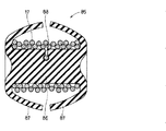
次に上記連結部材16の側部から引出されるとともに、先端部にプラグ18が接続されているコード17(図1参照)の巻取り装置85について説明する。この巻取り装置85は、図9〜図11に示すように、弾性材料、例えばゴムによって一体に成形された成形体であって、中間部分が棒状をなす巻取り部86に構成されている。なお巻取り部86は、必ずしも無空の棒状である必要はなく、筒体から構成されてもよい。また巻取り部86の両側にはそれぞれカップ状、あるいは半球状のフランジ87が一体に連結されている。なおフランジ87は、図9A、Bに示すように、両側のフランジ87が互いに背中合わせの状態と、図9Cに示すように、両側のフランジ87の外周縁が互いに接触あるいは近接する近接位置の2つの姿勢をとるようになっており、フランジ87を弾性変形させることによって、ある位置を境にして離反位置と近接位置の何れかの姿勢をとることになる。また上記巻取り部86には、その中間位置に、図10に示すような凹部から成る引掛け部88が形成され、この引掛け部88によって、巻取るコード17の一部を挿入して引掛けるようにしている。
Next, the winding
このようにゴムによって一体成形された巻取り装置85によってコード17を巻取る場合には、図9Aおよび図10に示すように、巻取り部86の引掛け部88にコード17を引掛ける。このような状態で、コード17を巻取り部86の外周部に図9Bおよび図10に示すように巻取る。なお巻取り量は、図1に示されるように、このコード17の必要長さよりも長い余剰の部分を巻取る長さとする。
Thus, when winding the
巻取り部86によってコード17を巻取る際には、図9A、B、および図10に示すように、巻取り部86の両側のカップ状をなすフランジ87を互いにそれらが背中合わせになるように弾性変形させておく。これによって巻取り部86に対するコード17の巻取りが容易になる。そして巻取りを終わったならば、両側のフランジ87を図9Cおよび図11に示すように、近接状態となるように弾性変形させる。このフランジ87の変形動作は、フランジ87を所定の位置を越えて弾性変形させることによって、フランジ87の外周縁の部分が互いに近接あるいは当接する姿勢をとるようにする。このような姿勢に変化させると、とくに図9Cに示すように、巻取り装置85が全体としてほぼ球状をなすとともに、巻取り部86によって巻取られたコード17が外からほとんど見えなくなる。しかもフランジ87によって内部の巻取り部を覆っているために、コード17が不測に解けることがなくなる。
When winding the
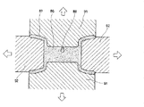
このような巻取り装置85を成形するための成形装置は、図12に示される。すなわちここでは、巻取り部86の軸線方向と直交する上下の方向に開閉自在な一対の第1の成形型91と、巻取り部86の軸線方向に開閉自在な第2の成形型92とを備えている。これらの成形型91、92を互いに閉じることによって、これらの成形型の間に形成されるキャビティ内に、溶融したゴムを射出し、成形することによって、巻取り装置85が一体成形されるようになる。このような巻取り装置は、上述の如く、ゴムの射出成形体であるために、一体であるとともに、フランジ87が弾性変形可能な構造をなしている。また単一の部品点数の巻取り装置85が製造されるようになる。
A forming apparatus for forming such a winding
このように本実施の形態においては、携帯電話機20と接続されたコード17をぜんまいばね29を内蔵するリール27で巻取るストラップ装置方式のヘッドホン・ヘッド装置において、クリップばね58を有する連結部材16を用いることによって、重量がある携帯電話機20であっても、この携帯電話機20の重量に関係なくずり下がることがなくなり、しかも引出す際にも、弱い弾性復元力のぜんまいばね29に抗して軽快に引出すことができ、またぜんまいばね29によるリール27の巻取り力も強すぎることがなくなる。また携帯電話機20をコード17にプラグ18を介して連結したことによって、コード17の長さを調整できるために、携帯電話機20によって、ワンセグの機能を利用してテレビジョン受像機を視聴する際に、ネックストラップ10によって携帯電話機20を首から下げたままの状態で視聴することができる。また自動改札機のタッチセンサとアクセスする際にも、図2に示すように、携帯電話機20を容易にタッチセンサにかざすことができ、その際にネックストラップ10をいちいち胸元から取外す必要がなくなる。またヘッドセットとして用いる場合に、プラグ18の内部にマイクロホン70を配置することによって、マイクロホン70のシールド線をマイクロホン内部で完結させることができ、巻取り装置で巻取られるコード17はオーディオ信号だけで済むために、線材構成が簡単で、コード17も細くできるために、巻取り部分の小型軽量化と、コードの断線防止による耐久性の向上が可能になる。また接続用プラグ付きコード17の余剰部分を巻取り装置85(図1参照)によって巻取ったり、あるいはまたコード17のこの部分をカールコードとすることによって、コード17の余分な部分がはみ出すことがなくなる。
As described above, in the present embodiment, in the headphone / head device of the strap device type in which the
すなわち、コード17の連結部材16の側部から引出された部位であって、プラグ18を先端に接続しているコード17の余剰部分が、巻取り装置85によって巻取られるようになっている。このような巻取り装置85は、上述の如く、一体成形されたゴムから構成されている。そしてこのような巻取り装置は、図9AおよびBに示すように、巻取り部86の両側のフランジ87を互いに離反状態にし、この状態で巻取り部86上にコード17を巻取るとともに、所定の長さのコード17を巻取った後に、図9Cに示すように、両側のフランジ87を、それらの外周縁が互いに当接または近接する近接位置となるように弾性変形させるようにしている。従って図9Cに示すように、ほぼ球状をなす巻取り装置内に余剰のコード17が巻取られることになり、これによって余剰のコード17の処理が容易に行なわれることになる。
That is, a surplus portion of the
以上本願発明を図示の実施の形態によって説明したが、本願発明は上記実施の形態によって限定されることなく、本願発明の技術的思想の範囲内において各種の変更が可能である。例えば上記実施の形態における連結部材16と巻取り装置13の筒状口部15との係合構造としては、必ずしもクリップばね58を用いた構造にする必要はなく、その他各種の係合構造を任意に選択可能である。またこの吊下げ装置は、必ずしも携帯電話機20の吊下げ装置に限定されることなく、その他各種の携帯式電子機器の吊下げ装置として広く利用可能である。
Although the present invention has been described above with reference to the illustrated embodiments, the present invention is not limited to the above-described embodiments, and various modifications can be made within the scope of the technical idea of the present invention. For example, the engagement structure between the connecting
本願発明は、携帯電話機をネックストラップによって吊下げるための吊下げ装置として広く利用可能である。 The present invention can be widely used as a hanging device for hanging a mobile phone with a neck strap.
10…ネックストラップ、11…コード、12…イヤホン、13…巻取り装置、14…押え、15…筒状口部、16…連結部材、17…コード、18…プラグ、20…携帯電話機、21…吊下げ紐、25…シャーシ、26…支軸、27…リール、28…凹部、29…ぜんまいばね、30…ブラシ、35…フロントカバー、36…リヤカバー、37…支軸、38…ホルダ、39…ボール、40…ロック円板、43、44…半筒状部、45…係合溝、46…押えリング、51…コードホルダ、52…背面側押え、53…操作部材、54…支軸、55…軸受、56…巻ばね、57…フック、58…クリップばね、59…スリット、62…取付け部材、67、68…プラグケース、69…回路基板、70…マイクロホン、71…操作釦、75…外周側の溝、76…壁部、77…V字状ロック部、78…内周側の溝、79…連通溝、80…最大引込み位置、81…壁部、85…巻取り装置、86…巻取り部、87…フランジ、88…引掛け部、91…第1の成形型、92…第2の成形型
DESCRIPTION OF
Claims (5)
前記巻取り部の口部の近傍に設けられた係合部と、
前記コードに取付けられており、前記口部の係合部と係合および解除可能な連結部材と、
を備え、
前記コードは、前記連結部材内を挿通されるとともに前記連結部材の側部から引き出され、該引き出されたコードの先端にプラグを有し、前記プラグを介して前記電子機器又は電子部品に接続され、
前記連結部材には吊下げ紐が取り付けられ、前記吊下げ紐を介して前記電子機器又は電子部品が吊下げられ、
前記係合部は、前記連結部材と係合および解除する方向に対して垂直な方向に溝を有し、
前記連結部材は、前記溝に対して前記垂直な方向から係合および離間するクリップ部を有し、該クリップ部が前記溝に係合および離間することにより前記係合部との係合および解除が行われる
吊下げ装置。 A winding portion that has a reel for winding a cord, and draws out the cord connected to the electronic device or electronic component by rotation of the reel from the mouth portion of the housing, and winds the cord through the mouth portion;
An engaging portion provided in the vicinity of the mouth of the winding portion;
A connecting member attached to the cord and capable of engaging and releasing with an engaging portion of the mouth;
With
The cord is inserted through the coupling member and pulled out from a side portion of the coupling member. The cord has a plug at the leading end of the drawn cord, and is connected to the electronic device or electronic component through the plug. ,
A hanging string is attached to the connecting member, and the electronic device or electronic component is suspended through the hanging string ,
The engagement portion has a groove in a direction perpendicular to a direction in which the engagement member is engaged and released.
The connecting member has a clip portion that engages and separates from the direction perpendicular to the groove, and the clip portion engages and separates from the groove when the clip portion engages and separates from the groove. The hanging device where is performed .
請求項1に記載の吊下げ装置。 The suspension device according to claim 1, further comprising a microphone inside the plug.
請求項1に記載の吊下げ装置。 The suspension device according to claim 1, wherein an operation button is attached to the plug.
請求項1に記載の吊下げ装置。 The suspension device according to claim 1, wherein the winding portion has a length in which the cord is drawn out in a range of 0 to 0.6 m.
をさらに有し、
前記第2の巻取り部は、前記コードの余分な長さの部分を巻き取る
請求項1に記載の吊下げ装置。 A second winding portion attached to the cord and disposed at a predetermined position between the plug and the connecting member;
Further comprising
The suspension device according to claim 1, wherein the second winding unit winds up an extra length portion of the cord.
Priority Applications (4)
| Application Number | Priority Date | Filing Date | Title |
|---|---|---|---|
| JP2007132877A JP4882863B2 (en) | 2007-05-18 | 2007-05-18 | Hanging device |
| TW097115744A TWI373269B (en) | 2007-05-18 | 2008-04-29 | Hanging device |
| CN200810099067XA CN101309564B (en) | 2007-05-18 | 2008-05-16 | Hanging device |
| US12/122,182 US7802746B2 (en) | 2007-05-18 | 2008-05-16 | Hanging device |
Applications Claiming Priority (1)
| Application Number | Priority Date | Filing Date | Title |
|---|---|---|---|
| JP2007132877A JP4882863B2 (en) | 2007-05-18 | 2007-05-18 | Hanging device |
Publications (3)
| Publication Number | Publication Date |
|---|---|
| JP2008288960A JP2008288960A (en) | 2008-11-27 |
| JP2008288960A5 JP2008288960A5 (en) | 2009-09-10 |
| JP4882863B2 true JP4882863B2 (en) | 2012-02-22 |
Family
ID=40026511
Family Applications (1)
| Application Number | Title | Priority Date | Filing Date |
|---|---|---|---|
| JP2007132877A Expired - Fee Related JP4882863B2 (en) | 2007-05-18 | 2007-05-18 | Hanging device |
Country Status (4)
| Country | Link |
|---|---|
| US (1) | US7802746B2 (en) |
| JP (1) | JP4882863B2 (en) |
| CN (1) | CN101309564B (en) |
| TW (1) | TWI373269B (en) |
Families Citing this family (34)
| Publication number | Priority date | Publication date | Assignee | Title |
|---|---|---|---|---|
| JP4882863B2 (en) * | 2007-05-18 | 2012-02-22 | ソニー株式会社 | Hanging device |
| US8777075B2 (en) * | 2008-09-05 | 2014-07-15 | Velopass, Llc | Combination hydration, nutrition, and pack apparatus for a bicycle |
| US8624836B1 (en) | 2008-10-24 | 2014-01-07 | Google Inc. | Gesture-based small device input |
| CN102348395A (en) * | 2009-03-10 | 2012-02-08 | 中谷进 | Article with fixing cord |
| JP2011082933A (en) * | 2009-10-09 | 2011-04-21 | Audio Technica Corp | Cord winding holder |
| US8746519B2 (en) * | 2010-01-15 | 2014-06-10 | West Coast Chain Mfg. Co. | Releasable attachment apparatus |
| AT509384A1 (en) | 2010-02-11 | 2011-08-15 | Proell Florian | HEAD SET |
| CH704484B1 (en) * | 2011-02-03 | 2013-09-13 | Huber+Suhner Ag | Cable carrier with a coil unit. |
| US9392349B2 (en) | 2012-03-30 | 2016-07-12 | Hybrid Skillz Inc. | Cable retraction system |
| US11432641B2 (en) | 2012-03-30 | 2022-09-06 | Advanced Access Technologies Llc | Retractable storage system |
| US8774446B2 (en) | 2012-03-30 | 2014-07-08 | Hybrid Skillz Inc. | Retractable storage system for handheld electronic device |
| US10237990B2 (en) | 2012-03-30 | 2019-03-19 | Advanced Access Technologies Llc | Retractable storage system |
| US10225639B2 (en) | 2012-03-30 | 2019-03-05 | Advanced Access Technologies Llc | Cable retraction system |
| US11412627B2 (en) | 2012-03-30 | 2022-08-09 | Advanced Access Technologies Llc | Multipurpose accessory and storage system |
| EP2845378A4 (en) | 2012-05-03 | 2016-03-30 | Turtlecell Llc | Case with headset retraction device |
| GB2509487A (en) * | 2012-11-12 | 2014-07-09 | Phonecatcher Ltd | Restraining means |
| US20140185856A1 (en) * | 2013-01-03 | 2014-07-03 | Koss Corporation | Lanyards for portable electronic devices |
| CN103825156A (en) * | 2014-02-21 | 2014-05-28 | 沁源县旺庄养殖专业合作社 | Pull type microphone cord of fixed-line telephone |
| US9277744B1 (en) * | 2014-04-16 | 2016-03-08 | Hunter Kane Sanders | Lanyard game strap |
| US9718640B2 (en) * | 2014-09-05 | 2017-08-01 | Buttonsmith Inc. | Retractable badge reel with button display |
| JP6202279B2 (en) * | 2014-09-08 | 2017-09-27 | カシオ計算機株式会社 | Stringed input pen and portable electronic device |
| US9936793B2 (en) | 2014-12-28 | 2018-04-10 | Emma Van Fox Grossman | Signal cable lanyard |
| US9144293B1 (en) * | 2015-01-21 | 2015-09-29 | Ducks, Ducks & More Ducks, LLC | Duck call organizer |
| USD772821S1 (en) | 2015-06-11 | 2016-11-29 | Oculus Vr, Llc | Remote control unit |
| US9801295B2 (en) * | 2015-11-05 | 2017-10-24 | Oculus Vr, Llc | Remote control unit with lanyard attachment mechanism |
| CN107197060B (en) * | 2016-03-15 | 2021-01-15 | 富泰华工业(深圳)有限公司 | Suspension device |
| CN106535023A (en) * | 2016-12-26 | 2017-03-22 | 歌尔股份有限公司 | Beck-wearing earphone and control mode thereof |
| US10187105B2 (en) * | 2017-06-19 | 2019-01-22 | Shenzhen Shengmalinuo Science and Technology Co., LTD. | Portable product lanyard |
| US10926576B2 (en) | 2017-09-21 | 2021-02-23 | Comsero Inc. | Retractable boundary apparatus and system |
| US10413805B2 (en) | 2017-10-10 | 2019-09-17 | Tosbl, LLC | Slip prevention apparatus and method for snow equipment |
| US10633217B2 (en) * | 2017-12-20 | 2020-04-28 | Precision Dynamics Corporation | Reel housing for dual use |
| WO2020039437A1 (en) * | 2018-08-22 | 2020-02-27 | Igc Tek Inc. | Device for hands-free hanging a hand-operated tool |
| RU2688056C1 (en) * | 2018-09-04 | 2019-05-20 | Владимир Александрович Парамошко | Method of protecting a mobile phone from falling to the floor |
| CN113233326A (en) * | 2021-05-21 | 2021-08-10 | 刘曙光 | Crane trolley set carrying and fixing device |
Family Cites Families (27)
| Publication number | Priority date | Publication date | Assignee | Title |
|---|---|---|---|---|
| US3314696A (en) * | 1964-02-11 | 1967-04-18 | Perfecting Service Company | Quick connect coupling |
| JPS5791389A (en) | 1980-11-28 | 1982-06-07 | Toyoda Autom Loom Works Ltd | Swash plate type compressor |
| JPS61183081A (en) * | 1985-02-08 | 1986-08-15 | 株式会社日立製作所 | Handrail for man conveyor |
| US4802638A (en) * | 1987-07-29 | 1989-02-07 | Motorola, Inc. | Cord stowage apparatus |
| JPH03284U (en) * | 1989-05-25 | 1991-01-07 | ||
| JPH0371119U (en) * | 1989-11-13 | 1991-07-18 | ||
| JPH03113889U (en) * | 1990-03-09 | 1991-11-21 | ||
| JP2743223B2 (en) | 1991-08-01 | 1998-04-22 | キヤノン株式会社 | Document scanning device |
| JPH07312791A (en) * | 1993-06-08 | 1995-11-28 | Naohiro Murakami | Headphone carrying device with two-stage cord automatic winding type remote controller |
| FI107002B (en) * | 1994-01-13 | 2001-05-15 | Nokia Mobile Phones Ltd | Hands free or HF device for mobile phone |
| JPH08237349A (en) * | 1995-02-22 | 1996-09-13 | Meiku Kogyo:Kk | Earphone cord winder for portable telephone set |
| US5954288A (en) * | 1998-08-24 | 1999-09-21 | Shih; Yung-Le | Extensible hanging device |
| JP2000115875A (en) * | 1998-09-30 | 2000-04-21 | Olympus Optical Co Ltd | Microphone device |
| TW421356U (en) * | 1999-05-17 | 2001-02-01 | Liau Sheng Shing | Improved structure of wire reel |
| JP2001197919A (en) * | 2000-01-17 | 2001-07-24 | Sakan:Kk | Neck strap |
| JP2001292218A (en) * | 2000-04-05 | 2001-10-19 | Teimusu Works:Kk | Earphone cord take-up winder |
| JP2001313991A (en) * | 2000-05-01 | 2001-11-09 | Casio Comput Co Ltd | Headphone |
| US7665684B2 (en) * | 2001-08-10 | 2010-02-23 | Hammerhead Industries, Inc | Retracting tether for cell phones, pagers and PDA's |
| US20030142817A1 (en) * | 2002-01-31 | 2003-07-31 | Liao Sheng Hsin | Earphone cable-receiving device with power recharge function |
| US6966519B2 (en) * | 2002-06-13 | 2005-11-22 | Hammerhead Industries | Rotatable retracting apparatus |
| TW576610U (en) * | 2002-12-19 | 2004-02-11 | Guo-Yang Wei | Improved coaxial line storage wheel device |
| JP2006166973A (en) * | 2004-12-13 | 2006-06-29 | Kyosuke Natori | Strap for cellular phone |
| US7957541B2 (en) * | 2006-01-27 | 2011-06-07 | Sony Ericsson Mobile Communications Ab | Acoustic compliance adjuster |
| JP4899770B2 (en) * | 2006-10-11 | 2012-03-21 | ソニー株式会社 | Headphone device |
| JP4882863B2 (en) * | 2007-05-18 | 2012-02-22 | ソニー株式会社 | Hanging device |
| JP2008288961A (en) * | 2007-05-18 | 2008-11-27 | Sony Corp | Stringlike body winder and manufacturing method thereof |
| JP4985125B2 (en) * | 2007-06-08 | 2012-07-25 | ソニー株式会社 | Winding device and suspension device using the winding device |
-
2007
- 2007-05-18 JP JP2007132877A patent/JP4882863B2/en not_active Expired - Fee Related
-
2008
- 2008-04-29 TW TW097115744A patent/TWI373269B/en not_active IP Right Cessation
- 2008-05-16 CN CN200810099067XA patent/CN101309564B/en not_active Expired - Fee Related
- 2008-05-16 US US12/122,182 patent/US7802746B2/en not_active Expired - Fee Related
Also Published As
| Publication number | Publication date |
|---|---|
| CN101309564A (en) | 2008-11-19 |
| TW200911003A (en) | 2009-03-01 |
| US7802746B2 (en) | 2010-09-28 |
| CN101309564B (en) | 2011-11-23 |
| US20080283651A1 (en) | 2008-11-20 |
| TWI373269B (en) | 2012-09-21 |
| JP2008288960A (en) | 2008-11-27 |
Similar Documents
| Publication | Publication Date | Title |
|---|---|---|
| JP4882863B2 (en) | Hanging device | |
| US20130129138A1 (en) | Multi-function phone case integrating retractable earphones | |
| US7416099B2 (en) | Neck strap for mobile electronic device | |
| US6731956B2 (en) | Retractable cord for a mobile phone or other wireless device | |
| US7151912B1 (en) | Cable retractor for an electronic device | |
| US20120314351A1 (en) | Attachable Extendable and Retractable Earpiece Cable Assembly for Mobile Communication and Sound Devices | |
| US20100224714A1 (en) | Cord adjustment device | |
| CN215499103U (en) | Electronic equipment protective housing and vehicle-mounted electronic equipment support | |
| CN112566525A (en) | Holding member | |
| JP4985125B2 (en) | Winding device and suspension device using the winding device | |
| KR101216318B1 (en) | Mobile phone having funcion of winding wire of earphone | |
| CN107027078B (en) | Wearable earphone accessory, wireless earphone and earphone product | |
| KR20000059278A (en) | Hands-free device for mobile telephones | |
| JP2008288961A (en) | Stringlike body winder and manufacturing method thereof | |
| KR101731827B1 (en) | Holder for portable terminal | |
| KR100725628B1 (en) | Wireless headset | |
| WO2002071795A1 (en) | Fixable-wire earphone | |
| JP3237622B2 (en) | Mobile terminal device strap structure | |
| KR100760341B1 (en) | Sound instrument | |
| JP3361304B2 (en) | Mobile phone attachment and mobile phone with attachment | |
| CN220023020U (en) | From wired earphone of taking in function | |
| KR200364568Y1 (en) | Earphone | |
| KR101479605B1 (en) | eardog earphone | |
| KR200204783Y1 (en) | A neckwear type portable audio player | |
| KR200430647Y1 (en) | Case of Sound instrument |
Legal Events
| Date | Code | Title | Description |
|---|---|---|---|
| A521 | Request for written amendment filed |
Free format text: JAPANESE INTERMEDIATE CODE: A523 Effective date: 20090724 |
|
| A621 | Written request for application examination |
Free format text: JAPANESE INTERMEDIATE CODE: A621 Effective date: 20090724 |
|
| RD02 | Notification of acceptance of power of attorney |
Free format text: JAPANESE INTERMEDIATE CODE: A7422 Effective date: 20100118 |
|
| RD04 | Notification of resignation of power of attorney |
Free format text: JAPANESE INTERMEDIATE CODE: A7424 Effective date: 20100326 |
|
| A977 | Report on retrieval |
Free format text: JAPANESE INTERMEDIATE CODE: A971007 Effective date: 20101018 |
|
| A131 | Notification of reasons for refusal |
Free format text: JAPANESE INTERMEDIATE CODE: A131 Effective date: 20101104 |
|
| A521 | Request for written amendment filed |
Free format text: JAPANESE INTERMEDIATE CODE: A523 Effective date: 20101224 |
|
| A02 | Decision of refusal |
Free format text: JAPANESE INTERMEDIATE CODE: A02 Effective date: 20110531 |
|
| A521 | Request for written amendment filed |
Free format text: JAPANESE INTERMEDIATE CODE: A523 Effective date: 20110831 |
|
| A911 | Transfer to examiner for re-examination before appeal (zenchi) |
Free format text: JAPANESE INTERMEDIATE CODE: A911 Effective date: 20110909 |
|
| TRDD | Decision of grant or rejection written | ||
| A01 | Written decision to grant a patent or to grant a registration (utility model) |
Free format text: JAPANESE INTERMEDIATE CODE: A01 Effective date: 20111108 |
|
| A01 | Written decision to grant a patent or to grant a registration (utility model) |
Free format text: JAPANESE INTERMEDIATE CODE: A01 |
|
| A61 | First payment of annual fees (during grant procedure) |
Free format text: JAPANESE INTERMEDIATE CODE: A61 Effective date: 20111121 |
|
| FPAY | Renewal fee payment (event date is renewal date of database) |
Free format text: PAYMENT UNTIL: 20141216 Year of fee payment: 3 |
|
| FPAY | Renewal fee payment (event date is renewal date of database) |
Free format text: PAYMENT UNTIL: 20141216 Year of fee payment: 3 |
|
| LAPS | Cancellation because of no payment of annual fees |