JP4881285B2 - Lead storage device for pets - Google Patents

Lead storage device for pets Download PDF

Info

Publication number
JP4881285B2
JP4881285B2 JP2007315987A JP2007315987A JP4881285B2 JP 4881285 B2 JP4881285 B2 JP 4881285B2 JP 2007315987 A JP2007315987 A JP 2007315987A JP 2007315987 A JP2007315987 A JP 2007315987A JP 4881285 B2 JP4881285 B2 JP 4881285B2
Authority
JP
Japan
Prior art keywords
reel
lead
pin
main body
storage device
Prior art date
Legal status (The legal status is an assumption and is not a legal conclusion. Google has not performed a legal analysis and makes no representation as to the accuracy of the status listed.)
Expired - Fee Related
Application number
JP2007315987A
Other languages
Japanese (ja)
Other versions
JP2009136213A5 (en
JP2009136213A (en
Inventor
博文 木根
Current Assignee (The listed assignees may be inaccurate. Google has not performed a legal analysis and makes no representation or warranty as to the accuracy of the list.)
DoggyMan H A Co Ltd
Original Assignee
DoggyMan H A Co Ltd
Priority date (The priority date is an assumption and is not a legal conclusion. Google has not performed a legal analysis and makes no representation as to the accuracy of the date listed.)
Filing date
Publication date
Application filed by DoggyMan H A Co Ltd filed Critical DoggyMan H A Co Ltd
Priority to JP2007315987A priority Critical patent/JP4881285B2/en
Publication of JP2009136213A publication Critical patent/JP2009136213A/en
Publication of JP2009136213A5 publication Critical patent/JP2009136213A5/ja
Application granted granted Critical
Publication of JP4881285B2 publication Critical patent/JP4881285B2/en
Expired - Fee Related legal-status Critical Current
Anticipated expiration legal-status Critical

Links

Images

Classifications

    • AHUMAN NECESSITIES
    • A01AGRICULTURE; FORESTRY; ANIMAL HUSBANDRY; HUNTING; TRAPPING; FISHING
    • A01KANIMAL HUSBANDRY; CARE OF BIRDS, FISHES, INSECTS; FISHING; REARING OR BREEDING ANIMALS, NOT OTHERWISE PROVIDED FOR; NEW BREEDS OF ANIMALS
    • A01K27/00Leads or collars, e.g. for dogs
    • A01K27/003Leads, leashes
    • A01K27/004Retractable leashes

Description

本発明は、例えば犬の散歩の際に使用され犬との距離に応じてリードの引き出しおよび収納が行われるペット用のリード収納装置に関する。   The present invention relates to a lead storage device for a pet that is used when a dog walks, for example, and a lead is pulled out and stored according to the distance from the dog.

家庭で飼われる犬は、通常は1日に1回または2回の散歩のために敷地外に連れ出される。この散歩には、散歩用のリード(引き紐)が使用される。散歩用のリードとして、未使用時にはケースの中にリードが収納され、散歩時には活動する犬との距離に応じて繰り返しリードがケースから引き出され、繰り返しケースの中に収納されるリード収納装置も用意されている。   Dogs kept at home are usually taken out of the premises for a walk once or twice a day. For this walk, a walk lead (drawn string) is used. As a lead for walking, a lead storage device is also provided in which the lead is stored in the case when not in use, and the lead is repeatedly pulled out of the case according to the distance from the active dog when walking, and stored repeatedly in the case Has been.

また、散歩時においては、犬の自由な活動を規制する必要があるため、この種のリード収納装置には、リードがケースから自由に引き出されるのを防止するためのロック機構が設けられたものも開発されている(特許文献1、特許文献2)。
特開平4−360634号公報 特開2003−319729号公報
In addition, since it is necessary to regulate the free activity of the dog during a walk, this type of lead storage device is provided with a lock mechanism to prevent the lead from being pulled out of the case freely Have also been developed (Patent Document 1, Patent Document 2).
JP-A-4-360634 JP 2003-319729 A

しかし、特許文献1および特許文献2に記載されたリード収納装置は、いずれもリードが巻かれたリールに設けられたラチェット歯(特許文献1)または係合爪(特許文献2)に係合してリールをロックするストッパ(特許文献1)またはロック爪(特許文献2)の移動はリールの回転中心に向けて行われる。このようなストッパまたはロック爪は、一定以上の長さおよび一定以上の移動距離を要する。   However, each of the lead storage devices described in Patent Document 1 and Patent Document 2 is engaged with ratchet teeth (Patent Document 1) or engaging claws (Patent Document 2) provided on a reel around which a lead is wound. The stopper (Patent Document 1) or the lock pawl (Patent Document 2) that locks the reel is moved toward the rotation center of the reel. Such a stopper or lock claw requires a certain length or more and a certain moving distance.

そのため、ロック機構が大型化しリード収納装置も大型化するという問題があり、デザインの選択が制約されるという問題がある。
本発明は、上述の問題に鑑みてなされたもので、リードの繰り出しおよび巻き取りをロックすることができかつ小型化可能でデザインへの制約が少ないリード収納装置を提供することを目的とする。
Therefore, there is a problem that the lock mechanism is enlarged and the lead storage device is also enlarged, and there is a problem that design selection is restricted.
The present invention has been made in view of the above-described problems, and an object of the present invention is to provide a lead storage device that can lock lead feeding and winding, can be miniaturized, and has few restrictions on design.

前記目的を達成するため、本発明においては以下の技術的手段を講じた。
すなわち、本発明に係るペット用のリード収納装置は、付勢力を蓄える部材を備えリードが繰り出されるときに正回転して前記付勢力を蓄え前記付勢力により逆回転してリードを巻き取るリールと、前記リールと一体化されて前記リールの回転中心を中心とする円の周上に等間隔に複数配され前記円の径方向外方に凸であって前記リールとともに回転し停止する爪と、記爪よりも前記径方向外方において前記リールの回転軸に平行なピン軸を中心に回動可能であり、前記ピン軸に直交する方向に伸びて隣り合う前記爪の間に位置するときに前記リールの正回転および逆回転を阻止する係合部を有するロックピンと、その付勢力により隣り合う前記爪の間に前記係合部が位置するように前記ロックピンを回動させる付勢部材と、前記円の法線方向に往復移動可能でありその一方の移動端側に移動するとき前記ロックピンを押圧して隣り合う前記爪の間から前記係合部が抜け出るように回動させるロック解除部材と、板バネと、前記リール前記爪、前記ロックピン、前記付勢部材、前記ロック解除部材および前記板バネを内部に収納する本体と、を有し、前記ロック解除部材は、前記ピン軸に平行な面である当接面を有し、前記板バネは、湾曲する第1の部分と、前記第1の部分の一方の端に連続し前記第1の部分よりも小さな曲率半径で湾曲してかつその曲率中心が前記第1の部分の曲率中心の反対側にある第2の部分と、を有しおよび前記第1の部分および前記第2の部分の母線が前記リールの回転軸に平行となるように配されてその両端が移動不能に前記本体内に保持され、前記第2の部分が前記当接面を押圧して前記ロック解除部材の移動を妨げるように構成される
In order to achieve the above object, the present invention takes the following technical means.
That is, the lead storage device for a pet according to the present invention includes a reel that includes a member that stores an urging force, rotates forward when the lead is fed out, stores the urging force, and rotates backward by the urging force to wind the lead. a pawl which rotates stop with a plurality disposed is the reel a convex outward in the radial direction of the circle at equal intervals on the circumference of a circle centered on the rotation center of the is integrated with the reel reel , before tight it is rotatable about a parallel pin shaft to the rotation shaft of the reel in the outside of the front Ki径 direction than, between the pawl adjacent extending in a direction perpendicular to the pin axis wherein a lock pin having an engaging portion for preventing the forward rotation and reverse rotation of the reel, the locking pin is rotating such that the engagement portion between the claw adjacent the biasing force thereof is positioned when the position and a biasing member, of the circle A lock release member that is reciprocally movable in a linear direction and that rotates to move the engagement portion out of between the adjacent claws by pressing the lock pin when moving toward one of the moving ends; and a leaf spring When, the reel, the pawl, the Rokkupi down, before Symbol urging member, anda body for accommodating the lock releasing member and the plate spring therein, said lock release member is parallel to the pin axis The leaf spring is curved with a first portion that is curved, a curvature radius that is continuous with one end of the first portion and is smaller than the first portion, and A second portion whose center of curvature is opposite to the center of curvature of the first portion, and a bus line of the first portion and the second portion is parallel to the rotation axis of the reel It is arranged so that both ends are immovable and held in the main body. Is, the second portion is configured to prevent movement of the unlocking member to press the abutment surface.

記板バネは、前記ロック解除部材が前記一方の移動端に位置するときに、前記第2の部分が前記当接面から外れて前記ロック解除部材における他方の移動端側の端面に当接するように配置される
また、前記当接面は、前記ロック解除部材が前記他方の移動端から前記一方の移動端に移動するにしたがって前記第2の部分をその曲率中心側に移動させて前記板バネの第1の部分の曲率半径を小さくするように前記往復移動方向に対して傾斜している。
Before SL leaf spring, when the unlocking member is located at the moving end of the one, the second portion abuts against the end face of the second movement end side of the unlocking member disengaged from said abutment surface Are arranged as follows .
The abutment surface moves the second portion toward the center of curvature as the unlocking member moves from the other moving end to the one moving end , thereby causing the first spring of the leaf spring to move. It is inclined with respect to the reciprocating direction so as to reduce the radius of curvature of the portion .

好ましくは、前記付勢部材は、一方の腕が前記係合部の先端側に保持され他方の腕が前記本体に保持されそのコイル部分が前記ピン軸の外周にはめ込まれたコイルバネである。Preferably, the biasing member is a coil spring in which one arm is held on the distal end side of the engaging portion, the other arm is held on the main body, and a coil portion thereof is fitted on the outer periphery of the pin shaft.

本発明によると、リードの繰り出しおよび巻き取りをロックすることができかつ小型化可能でデザインへの制約が少ないリード収納装置を提供することができる。   ADVANTAGE OF THE INVENTION According to this invention, the lead | read | reed accommodation apparatus which can lock | feed out and wind up of a lead, can be reduced in size, and there are few restrictions on a design can be provided.

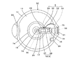
図1は本発明に係るリード収納装置1の正面図、図2はリード収納装置1の平面図、図3はリード収納装置1の本体2の左側面図、図4は第1本体カバー3の裏面図、図5はスライドスイッチ4の平面図、図6は板バネ5の斜視図、図7は第1本体カバー3を取り外した本体2の正面図、図8はリール停止装置11の概略図、および図9は本体2の組立概要図である。なお、図9において(c)はロックピン56の側面図、および(d)はロックピン56の正面図である。   1 is a front view of the lead storage device 1 according to the present invention, FIG. 2 is a plan view of the lead storage device 1, FIG. 3 is a left side view of the main body 2 of the lead storage device 1, and FIG. 5 is a plan view of the slide switch 4, FIG. 6 is a perspective view of the leaf spring 5, FIG. 7 is a front view of the main body 2 with the first main body cover 3 removed, and FIG. 8 is a schematic view of the reel stop device 11. FIG. 9 is an assembly schematic diagram of the main body 2. 9C is a side view of the lock pin 56, and FIG. 9D is a front view of the lock pin 56.

リード収納装置1は、本体2、リード6およびナスカン7からなる。
本体2は、第1本体カバー3、第2本体カバー8、リール9、ゼンマイバネ10、リール停止装置11およびキャップ12からなる。
第1本体カバー3は、第2本体カバー8とともに本体2の略円柱状の外観を形成する。また、第1本体カバー3は、第2本体カバー8と組み合わされて、内部にリール9、ゼンマイバネ10、リール停止装置11および巻き取られたリード6を収納する。
The lead storage device 1 includes a main body 2, a lead 6, and an eggplant 7.
The main body 2 includes a first main body cover 3, a second main body cover 8, a reel 9, a mainspring spring 10, a reel stop device 11, and a cap 12.
The first main body cover 3 forms a substantially cylindrical appearance of the main body 2 together with the second main body cover 8. The first main body cover 3 is combined with the second main body cover 8 to house the reel 9, the mainspring spring 10, the reel stop device 11, and the wound lead 6.

図4を参照して、第1本体カバー3は、略円板状の第1壁部13および第1壁部13の端縁から第1壁部13に対して垂直に連続する略円筒状の第1側壁部14、スライドスイッチ4および板バネ5で形成される。
第1壁部13には、内面の内方に、第1壁部13と同心円であって第1壁部13よりも高さが低い略円筒状のリール隔離部15が設けられている。リール隔離部15は、その円筒状の一部が欠落しており、両欠落端の間における第1壁部13には、リール隔離部15の法線方向に延びたスイッチ案内孔16が貫通している。スイッチ案内孔16の周囲は、リール隔離部15の欠落部分に略等しい幅でスイッチ案内溝17が設けられている。スイッチ案内溝17の長手方向両端は、後に説明するスライドスイッチ4におけるロック部18の長手方向端面の湾曲に合わせた、外方に凸となる曲面となっている。
Referring to FIG. 4, the first main body cover 3 has a substantially disc-shaped first wall portion 13 and a substantially cylindrical shape that is perpendicular to the first wall portion 13 from the edge of the first wall portion 13. The first side wall part 14, the slide switch 4 and the leaf spring 5 are formed.
The first wall portion 13 is provided with a substantially cylindrical reel separating portion 15 concentrically with the first wall portion 13 and having a height lower than that of the first wall portion 13 inside the inner surface. A part of the cylindrical shape of the reel isolating portion 15 is missing, and a switch guide hole 16 extending in the normal direction of the reel isolating portion 15 passes through the first wall portion 13 between both missing ends. ing. A switch guide groove 17 is provided around the switch guide hole 16 with a width substantially equal to the missing portion of the reel separating portion 15. Both ends in the longitudinal direction of the switch guide groove 17 are curved outwardly convex in accordance with the curvature of the longitudinal end surface of the lock portion 18 in the slide switch 4 described later.

また、第1壁部13は、スイッチ案内溝17の第1側壁部14に近い側の端面19の最先端部における接線が第1壁部13の端縁と交わる部分に、断面が円形のピン支持孔20を有する。
第1側壁部14は、スイッチ案内孔16の長手方向延長線上に、異なる曲率半径を有し断面形状が半円形であって隣あうそれぞれが段を有して連なる凹状の第1キャップ収容溝21を有する。第1側壁部14には、第1キャップ収容溝21の反対側に、ストラップを取り付けるための第1ストラップ用溝22が設けられている。
The first wall portion 13 is a pin having a circular cross section at a portion where the tangent at the most distal end portion of the end surface 19 of the switch guide groove 17 close to the first side wall portion 14 intersects the edge of the first wall portion 13. A support hole 20 is provided.
The first side wall portion 14 has a concave first cap housing groove 21 having a different curvature radius and a semicircular cross section on the longitudinal extension line of the switch guide hole 16 and having adjacent steps. Have The first side wall portion 14 is provided with a first strap groove 22 for attaching a strap on the opposite side of the first cap housing groove 21.

スライドスイッチ4は、スイッチ案内孔16に取り付けられており、図5に示されるように、操作部23とロック部18とからなる。操作部23は、主体が長円形の操作面24を有する板状体であって、操作面24の反対側の面25からは、長手方向に伸び断面形状が長円の連結部26が突出する。連結部26の厚さ(長円形断面の半円の直径)は、スイッチ案内孔16の幅に略等しく、連結部26は、スイッチ案内孔16内を支障なく移動可能である。   The slide switch 4 is attached to the switch guide hole 16 and includes an operation part 23 and a lock part 18 as shown in FIG. The operation portion 23 is a plate-like body having an oval operation surface 24 as a main body, and a connection portion 26 that extends in the longitudinal direction and has an oval cross-sectional shape protrudes from a surface 25 opposite to the operation surface 24. . The thickness of the connecting portion 26 (diameter of a semicircle having an oval cross section) is substantially equal to the width of the switch guide hole 16, and the connecting portion 26 can move within the switch guide hole 16 without any trouble.

ロック部18は、バネ押さえ部27とピン押さえ部28とからなり、図4における正面視では、全体として、スイッチ案内溝17の長手方向に伸びて、伸びた端面が曲面となった形状を有する。
バネ押さえ部27は、長手方向の一方の端から他方の端に向けて全体の略4分の3の範囲を占め、バネ押さえ部27の一方の側面29(図4における上側の側面。以下「当接面29」という。)は、内側に向かうにつれて他方の側面との距離が短くなるように内方に傾斜している。バネ押さえ部27には、連結部26の断面形状に略等しい断面形状の連結孔30が、その長手方向をロック部18の長手方向に一致させて設けられている。
The lock portion 18 includes a spring pressing portion 27 and a pin pressing portion 28, and has a shape in which the extended end surface is a curved surface extending in the longitudinal direction of the switch guide groove 17 as a whole in a front view in FIG. .
The spring pressing portion 27 occupies a substantially three-quarter range from one end in the longitudinal direction to the other end, and one side surface 29 of the spring pressing portion 27 (the upper side surface in FIG. The abutting surface 29 ") is inclined inward so that the distance from the other side surface becomes shorter toward the inside. A connecting hole 30 having a cross-sectional shape substantially equal to the cross-sectional shape of the connecting portion 26 is provided in the spring holding portion 27 so that the longitudinal direction thereof coincides with the longitudinal direction of the lock portion 18.

ピン押さえ部28は、スイッチ案内溝17に略等しい幅を有し、一方の表面がバネ押さえ部27の表面と同一面にあって、他方の表面(外面)31がバネ押さえ部27の他方の表面と段を形成している。つまり、ピン押さえ部28は、バネ押さえ部27よりも大きな厚さを有する。
スライドスイッチ4のスイッチ案内孔16への取り付けは、次のようにして行われる。最初に、操作部23の連結部26が、第1壁部13の外面側からスイッチ案内孔16にはめ込まれる。続いて、第1壁部13の内面側において、スイッチ案内孔16を突き抜けた連結部26が、ロック部18の連結孔30にはめ込まれる。このとき、ロック部18は、段を有しない面側から連結部26がはめ込まれる。連結部26は、スイッチ案内溝17の厚さとバネ押さえ部27の厚さとを加えた長さを有する。連結部26は、連結孔30において接着剤により固定される。
The pin pressing portion 28 has a width substantially equal to the switch guide groove 17, one surface is flush with the surface of the spring pressing portion 27, and the other surface (outer surface) 31 is the other surface of the spring pressing portion 27. Forms a step with the surface. That is, the pin pressing portion 28 has a larger thickness than the spring pressing portion 27.
The slide switch 4 is attached to the switch guide hole 16 as follows. First, the connecting portion 26 of the operation portion 23 is fitted into the switch guide hole 16 from the outer surface side of the first wall portion 13. Subsequently, on the inner surface side of the first wall portion 13, the connecting portion 26 penetrating the switch guide hole 16 is fitted into the connecting hole 30 of the lock portion 18. At this time, as for the lock part 18, the connection part 26 is engage | inserted from the surface side which does not have a step. The connecting portion 26 has a length obtained by adding the thickness of the switch guide groove 17 and the thickness of the spring pressing portion 27. The connecting part 26 is fixed in the connecting hole 30 with an adhesive.

スライドスイッチ4は、スイッチ案内孔16に取り付けられたときに、ロック部18におけるピン押さえ部28の外面31がリール隔離部15における環状の端面74よりも低くなるように構成されている。
スイッチ案内孔16に取り付けられたスライドスイッチ4は、連結部26がスイッチ案内孔16に案内され、ロック部18の段を有しない面側がスイッチ案内溝17に案内されて、円滑にリール隔離部15の法線方向に移動する。
When the slide switch 4 is attached to the switch guide hole 16, the outer surface 31 of the pin pressing portion 28 in the lock portion 18 is configured to be lower than the annular end surface 74 in the reel isolation portion 15.
In the slide switch 4 attached to the switch guide hole 16, the connecting portion 26 is guided to the switch guide hole 16, and the surface side without the step of the lock portion 18 is guided to the switch guide groove 17, so that the reel separating portion 15 is smoothly smoothed. Move in the normal direction of.

板バネ5は、大きな曲率半径を有して湾曲する第1部分32、第1部分32に連続しこれよりも小さな曲率半径で湾曲しかつその曲率中心が第1部分32の曲率中心の反対側にある第2部分33、第1部分32側の端である第1端34および第2部分33側の端である第2端35からなる。板バネ5は、第1部分32の曲率中心がリール隔離部15の内側なるようにしてリール隔離部15の内側に配される。板バネ5は、第1部分32の曲率半径が変化可能な状態で、第1端34がリール隔離部15に固定され、第2端35が欠落部分における一方の欠落端に固定されている。なお、ここでいう「固定」とは、例えば第1端34がリール隔離部15に設けられた孔に、第2端35が欠落端に設けられた孔にはめ込まれ、第1部分32に蓄えられた付勢力によって抜け出ないように保持された状態も含む。   The leaf spring 5 has a first portion 32 that is curved with a large radius of curvature, is continuous with the first portion 32 and is curved with a smaller radius of curvature, and the center of curvature is opposite to the center of curvature of the first portion 32. The second portion 33, the first end 34 on the first portion 32 side, and the second end 35 on the second portion 33 side. The leaf spring 5 is disposed inside the reel isolation portion 15 so that the center of curvature of the first portion 32 is inside the reel isolation portion 15. The leaf spring 5 has a first end 34 fixed to the reel separating portion 15 and a second end 35 fixed to one missing end of the missing portion in a state where the radius of curvature of the first portion 32 can be changed. Here, “fixed” means, for example, that the first end 34 is fitted into the hole provided in the reel separating portion 15 and the second end 35 is fitted into the hole provided at the missing end, and is stored in the first portion 32. It also includes a state where it is held so as not to escape by the applied urging force.

板バネ5は、スライドスイッチ4がスイッチ案内孔16に取り付けられる前にリール隔離部15に取り付けられる。そして、スライドスイッチ4がスイッチ案内孔16に取り付けられると、第2部分33の凸側の面は、ロック部18の当接面29側に押圧状態で当接する。
また、板バネ5は、スライドスイッチ4がスイッチ案内孔16に案内されて第1キャップ収容溝21側に移動するにしたがって、第2端35と当接面29との距離が短くなるように配されている。
The leaf spring 5 is attached to the reel isolation portion 15 before the slide switch 4 is attached to the switch guide hole 16. When the slide switch 4 is attached to the switch guide hole 16, the convex surface of the second portion 33 comes into contact with the contact surface 29 of the lock portion 18 in a pressed state.
Further, the leaf spring 5 is arranged so that the distance between the second end 35 and the contact surface 29 becomes shorter as the slide switch 4 is guided to the switch guide hole 16 and moves to the first cap housing groove 21 side. Has been.

第2本体カバー8は、第1本体カバー3と接合されて本体2の外観を形成し、接合面について第1本体カバー3と面対称となる形状を有する。したがって、第2本体カバー8は、略円板状の第2壁部36、および第2壁部36の端縁から第2壁部36に対して垂直に連続する略円筒状の第2側壁部37により形成される。第2側壁部37には、第1側壁部14の第1キャップ収容溝21に対応する位置に第2キャップ収容溝38、および第1側壁部14における第1ストラップ用溝22に対応する位置に第1ストラップ用溝22と面対称となる形状の第2ストラップ用溝39が設けられている。   The second main body cover 8 is joined to the first main body cover 3 to form the appearance of the main body 2, and has a shape that is plane-symmetric with the first main body cover 3 with respect to the joining surface. Therefore, the second main body cover 8 includes a substantially disc-shaped second wall portion 36 and a substantially cylindrical second side wall portion that is perpendicular to the second wall portion 36 from the edge of the second wall portion 36. 37. The second side wall 37 has a second cap housing groove 38 in a position corresponding to the first cap housing groove 21 in the first side wall 14 and a position corresponding to the first strap groove 22 in the first side wall 14. A second strap groove 39 having a shape symmetrical to the first strap groove 22 is provided.

第2壁部36には、第1壁部13におけるピン支持孔20に対応する位置に、後に説明するロックピン56における断面円形の径大部58を回動可能に支持するピン支持部40(図9参照)が設けられている。
ピン支持部40は、第2側壁部37の内周面の直近に垂直に伸びる、その断面が円の4分の1を切り取ったような形状のピン支持溝41を形成している。ピン支持部40における第2キャップ収容溝38側は、第2側壁部37と同じ高さのピン支持部40における他の部分よりも高くなっている。この、ピン支持部40における第2側壁部37よりも高い部分を誘導部42というものとする(図8および図9(a)参照)。
The second wall portion 36 is provided with a pin support portion 40 (in a position corresponding to the pin support hole 20 in the first wall portion 13) that rotatably supports a large diameter portion 58 having a circular cross section in the lock pin 56 described later. 9) is provided.
The pin support portion 40 forms a pin support groove 41 that extends perpendicularly to the immediate vicinity of the inner peripheral surface of the second side wall portion 37 and has a shape in which the cross section is cut out of a quarter of a circle. The second cap housing groove 38 side of the pin support portion 40 is higher than other portions of the pin support portion 40 having the same height as the second side wall portion 37. A portion higher than the second side wall portion 37 in the pin support portion 40 is referred to as a guide portion 42 (see FIGS. 8 and 9A).

第2側壁部37における第2キャップ収容溝38とピン支持部40との間には、後に説明するねじりコイルバネ57の端部が挿入される孔72が設けられている。
第2壁部36は、その内側の中心に、垂直に伸び外周断面が略円形のリール軸43を有する。リール軸43には、その軸心を含む係止溝44により2分されている。また、第2壁部36は、第1壁部13におけるリール隔離部15に対応する位置(接合面に対して面対称となる位置)に、リール隔離部15よりも高さの低い、リール軸43と同心円の環状のリール隔離部が設けられている。
A hole 72 into which an end portion of a torsion coil spring 57 described later is inserted is provided between the second cap housing groove 38 and the pin support portion 40 in the second side wall portion 37.
The second wall portion 36 has a reel shaft 43 that extends vertically and has a substantially circular outer peripheral cross section at the center of the inside thereof. The reel shaft 43 is divided into two by a locking groove 44 including the axis. In addition, the second wall portion 36 is positioned at a position corresponding to the reel isolation portion 15 in the first wall portion 13 (a position that is plane-symmetric with respect to the joining surface), and has a lower reel shaft than the reel isolation portion 15. An annular reel separating portion concentric with 43 is provided.

図9(b)を参照して、リール9は、円筒状の胴部45、胴部45の一端を閉じる下底部46、および胴部45の他端を閉じる上底部47からなる。
胴部45は、リード6を巻き取るためのものである。
下底部46は、略円形の板状であって、中心にはリール軸43が貫通可能な孔48が設けられている。
Referring to FIG. 9B, the reel 9 includes a cylindrical body portion 45, a lower bottom portion 46 that closes one end of the body portion 45, and an upper bottom portion 47 that closes the other end of the body portion 45.
The body 45 is for winding the lead 6.
The lower bottom portion 46 has a substantially circular plate shape, and a hole 48 through which the reel shaft 43 can pass is provided at the center.

図7をも参照して、上底部47は、基板49と爪部50とからなる。
基板49は、下底部46と略同じ径を有する円形板状であり、中心にはリール軸43が貫通可能な孔51が設けられている。
爪部50は、基板49の外側の面71上に肉厚部分として形成され、基板49と同心円である環状の支持面52、および同一形状の8つの爪53を有する。
Referring also to FIG. 7, the upper bottom portion 47 includes a substrate 49 and a claw portion 50.
The substrate 49 has a circular plate shape having substantially the same diameter as the lower bottom portion 46, and a hole 51 through which the reel shaft 43 can pass is provided at the center.
The claw portion 50 is formed as a thick portion on the outer surface 71 of the substrate 49, and has an annular support surface 52 that is concentric with the substrate 49, and eight claws 53 having the same shape.

支持面52は、その外側端縁の径がリール隔離部15の外径と同じまたはそれより大きく、その内側端縁の径がリール隔離部15の外径よりも小さい。
爪53は、支持面52よりも肉厚となっており、支持面52の外側端縁の外方に、周方向に等間隔に配されている。爪53は、正面視(図7および図8)において、鈍角と1つの頂角とを支持面52の外側端縁の近傍に配した鈍角三角形を基礎とする形状を有する。爪53は、鈍角三角形おける鈍角を形成しない辺に相当する面が外方に凸状の曲線で形成され、かつこの面の外方端において他の1辺に相当する面との間に形成される頂角を湾曲線(湾曲面)に置き換えたような形状である。以下、爪53における、鈍角から外方に伸び正面視がこの湾曲線の面に至る面を係合面54といい、この係合面54と外方において連続する「鈍角三角形おける鈍角を形成しない辺」に相当する面を湾曲側面55という。係合面54は平面であるが、外方に向けて凸状の曲面または内方に向けて凹状の曲面とすることができる。
The diameter of the outer edge of the support surface 52 is the same as or larger than the outer diameter of the reel separating part 15, and the diameter of the inner edge is smaller than the outer diameter of the reel separating part 15.
The claws 53 are thicker than the support surface 52, and are arranged at equal intervals in the circumferential direction outside the outer edge of the support surface 52. The nail | claw 53 has a shape based on the obtuse angle triangle which distribute | arranged the obtuse angle and one apex angle to the vicinity of the outer edge of the support surface 52 in front view (FIG. 7 and FIG. 8). The claw 53 is formed between the surface corresponding to the side that does not form the obtuse angle in the obtuse triangle and the surface corresponding to the other side at the outer end of the surface. The vertical angle is replaced with a curved line (curved surface). Hereinafter, a surface of the claw 53 that extends outward from the obtuse angle and reaches the surface of the curved line when viewed from the front is referred to as an engagement surface 54. The obtuse angle in the obtuse triangle that does not form the obtuse angle triangle is continuous with the engagement surface 54. A surface corresponding to “side” is referred to as a curved side surface 55. The engaging surface 54 is a flat surface, but may be a curved surface convex toward the outside or a curved surface concave toward the inside.

爪53は、その外方の最先端が基板49の端縁よりも内方に、基板49の端縁と適度な距離を有して配されている。
ゼンマイバネ10は、幅に比べて極めて長い弾性を有する金属板が渦巻き状に巻かれて形成されたバネである。ゼンマイバネ10の内側端部は、内側に鋭角に折り曲げられている。
The claw 53 is arranged at an appropriate distance from the edge of the substrate 49 such that the outermost tip of the claw 53 is inward of the edge of the substrate 49.
The mainspring 10 is a spring formed by spirally winding a metal plate having elasticity that is extremely longer than its width. The inner end of the spring spring 10 is bent at an acute angle inward.

図7ないし図9において、リール停止装置11は、ロックピン56およびねじりコイルバネ57からなる。
ロックピン56は、円柱状の径大部58、径大部58の一端に段を有して連続し径大部58よりも径小で長さの短い径小部59、および径大部58の径小部59側端から直角に伸びる係合部60からなる。径大部58は、第2本体カバー8におけるピン支持溝41の内面の曲率半径よりも僅かに小さい半径を有し、ピン支持溝41内で回動可能である。径小部59は、ピン支持孔20の径よりも僅かに小さい径を有し、ピン支持孔20内で回動可能である。
7 to 9, the reel stop device 11 includes a lock pin 56 and a torsion coil spring 57.
The lock pin 56 has a cylindrical large diameter portion 58, a step having one end of the large diameter portion 58, a continuous small diameter portion 59 having a smaller diameter and a shorter length than the large diameter portion 58, and a large diameter portion 58. The engagement portion 60 extends at a right angle from the side end of the small diameter portion 59. The large-diameter portion 58 has a radius slightly smaller than the radius of curvature of the inner surface of the pin support groove 41 in the second main body cover 8, and can rotate within the pin support groove 41. The small diameter portion 59 has a diameter slightly smaller than the diameter of the pin support hole 20, and can rotate within the pin support hole 20.

係合部60は、爪53の厚さと同等またはやや小さな厚さを有する基部61、および先端側において長手方向に一定の長さを有し基部61の略2倍であって爪53の厚さよりも大きな厚さを有する係止部62からなる。係合部60の先端面73(係止部62の先端側面でもある)は、湾曲する曲面となっている。係止部62(である肉厚部分)は、基部61に対して径小部59側に偏っており(図9(c)参照)、基部61の径大部58側の面63は係合部60全体に渡り平坦である。基部61の先端側には、ねじりコイルバネ57の一方の腕部分64を挿入させて保持する孔65が貫通している。係合部60において長手方向に伸びリール9側に向く側面は、凹状に湾曲した曲面(「係合部湾曲面66」という)となっており、その湾曲の度合いは、爪53における湾曲側面55よりも小さい。   The engaging portion 60 has a base portion 61 having a thickness that is equal to or slightly smaller than the thickness of the claw 53, and has a constant length in the longitudinal direction on the distal end side, and is approximately twice the base portion 61. The locking portion 62 has a large thickness. The distal end surface 73 of the engaging portion 60 (also the distal end side surface of the locking portion 62) is a curved surface that is curved. The locking portion 62 (which is a thick portion) is biased toward the small diameter portion 59 with respect to the base portion 61 (see FIG. 9C), and the surface 63 on the large diameter portion 58 side of the base portion 61 is engaged. The entire portion 60 is flat. A hole 65 for inserting and holding one arm portion 64 of the torsion coil spring 57 passes through the distal end side of the base 61. A side surface extending in the longitudinal direction toward the reel 9 in the engagement portion 60 is a curved surface curved in a concave shape (referred to as an “engagement portion curved surface 66”). Smaller than.

ねじりコイルバネ57は、コイル部分の両端に連続するそれぞれの腕部分64,67が付勢方向に対して直角に曲げられている。
キャップ12は、第1本体カバー3と第2本体カバー8とが接合されたときに第1キャップ収容溝21と第2キャップ収容溝38とが形成する貫通孔に保持される。したがって、キャップ12は、貫通孔の内面形状と略等しい外形を有する。キャップ12には、軸心を貫通する孔68が設けられている。
In the torsion coil spring 57, the respective arm portions 64 and 67 continuous at both ends of the coil portion are bent at right angles to the urging direction.
The cap 12 is held in a through hole formed by the first cap housing groove 21 and the second cap housing groove 38 when the first main body cover 3 and the second main body cover 8 are joined. Therefore, the cap 12 has an outer shape substantially equal to the inner shape of the through hole. The cap 12 is provided with a hole 68 that passes through the shaft center.

第1本体カバー3および第2本体カバー8はポリプロピレン樹脂、スライドスイッチ4およびリール9はポリアミド樹脂で製作される。
リード6は、ナイロン繊維で編まれた丸紐である。
ナスカン7は、リード6を、例えば犬の首輪に取り付けられたDカンに連結するためのものである。ナスカン7は、熱可塑性エラストマー(合成ゴム)で製作された接続具69によりリード6に連結されている。ナスカン7は、ダイキャスト製品であり、一般に広く使用されるものである。
The first main body cover 3 and the second main body cover 8 are made of polypropylene resin, and the slide switch 4 and the reel 9 are made of polyamide resin.
The lead 6 is a round string knitted with nylon fibers.
The eggplant 7 is for connecting the lead 6 to a D-can attached to, for example, a dog collar. The eggplant 7 is connected to the lead 6 by a connecting tool 69 made of a thermoplastic elastomer (synthetic rubber). Naskan 7 is a die-cast product and is generally widely used.

次に、リード収納装置1の組立方法を説明する。
ゼンマイバネ10を胴部45内に収納させてリール9が組み立てられる。ゼンマイバネ10の外側の端は、胴部45の内面に直接にまたは間接に固定される。また、ゼンマイバネ10は、爪53との関係において爪53が傾く方向とは逆側に巻き径が小さくなるように、つまり、爪53が傾く方向とは逆の方向(図7における矢印R方向)にゼンマイバネ10の付勢力が働くように、胴部45内に収納される。
Next, a method for assembling the lead storage device 1 will be described.
The mainspring 10 is housed in the body 45 and the reel 9 is assembled. The outer end of the spring spring 10 is fixed directly or indirectly to the inner surface of the body 45. Further, the spring spring 10 has a winding diameter that is smaller than the direction in which the claw 53 is inclined in relation to the claw 53, that is, the direction opposite to the direction in which the claw 53 is inclined (direction of arrow R in FIG. 7). The mainspring spring 10 is housed in the body portion 45 so that the urging force of the mainspring spring 10 is applied.

次に、リード6の一端がリール9の基板49に固定されて、胴部45の外周に巻かれる。リード6の他端は、キャップ12の孔68に通された後に、接続具69を介してナスカン7に接続される。
ナスカン7がキャップ12に接触する程度にまでリード6が巻かれたリール9の下底部46側の孔48に、第2本体カバー8のリール軸43を挿通させる。続いて、上底部47の孔51からゼンマイバネ10の内側の鋭角に曲げられた端が操作されて、この鋭角に曲げられた端がリール軸43に設けられた係止溝44にはめ込まれる。この後、上底部47の孔51にリール軸43が通されて、リール9は第2本体カバー8に回動可能に取り付けられる。第2本体カバー8のピン支持部40における誘導部42は、その先端面70がリール9が第1本体カバー3に取り付けられた後の基板49の外側の面71が属する面内に存在するように、その高さが決定されている。
Next, one end of the lead 6 is fixed to the substrate 49 of the reel 9 and wound around the outer periphery of the body 45. The other end of the lead 6 is passed through the hole 68 of the cap 12, and then connected to the eggplant 7 via the connection tool 69.
The reel shaft 43 of the second main body cover 8 is inserted into the hole 48 on the lower bottom 46 side of the reel 9 around which the lead 6 is wound so that the eggplant 7 comes into contact with the cap 12. Subsequently, an end bent at an acute angle inside the mainspring spring 10 is operated from the hole 51 of the upper bottom portion 47, and the end bent at the acute angle is fitted into a locking groove 44 provided in the reel shaft 43. Thereafter, the reel shaft 43 is passed through the hole 51 of the upper bottom portion 47, and the reel 9 is rotatably attached to the second main body cover 8. Guiding section 42 of the pin support portion 40 of the second body cover 8 has its distal end surface 70, the reel 9 is present on the outer surface 71 belongs in the plane of the substrate 49 after being attached to the first cover 3 As such, its height has been determined.

次に、ロックピン56の径大部58がピン支持溝41内にはめ込まれる。ロックピン56は、係合部60における径大部58側の平坦な面63が、同一平面内にあるリール9の基板49の外側の面71および誘導部42の先端面70に当接する。ねじりコイルバネ57は、そのコイル部分が径小部59にはめ込まれ、その一方の腕部分64が係合部60の孔65に、他方の腕部分67が第2側壁部37に設けられた孔72に差し込まれて、ロックピン56を係合部60が爪部50側に回動するように付勢する。   Next, the large diameter portion 58 of the lock pin 56 is fitted into the pin support groove 41. In the lock pin 56, the flat surface 63 on the large diameter portion 58 side of the engaging portion 60 abuts on the outer surface 71 of the substrate 49 of the reel 9 and the distal end surface 70 of the guide portion 42 in the same plane. The coil portion of the torsion coil spring 57 is fitted into the small diameter portion 59, and one arm portion 64 is provided in the hole 65 of the engaging portion 60 and the other arm portion 67 is provided in the second side wall portion 37. Then, the lock pin 56 is urged so that the engaging portion 60 rotates toward the claw portion 50 side.

次に、第1本体カバー3が第2本体カバー8に接合される。このとき、第1本体カバー3におけるスライドスイッチ4は、第1キャップ収容溝21側の移動端とは逆側の移動端(ロック位置)に移動させておく。そうすると、接合時にロック部18のピン押さえ部28がロックピン56の係止部62よりも内側に位置することになり、第1本体カバー3と第2本体カバー8とを容易に接合することができる。   Next, the first main body cover 3 is joined to the second main body cover 8. At this time, the slide switch 4 in the first main body cover 3 is moved to the moving end (lock position) opposite to the moving end on the first cap housing groove 21 side. If it does so, the pin press part 28 of the lock part 18 will be located inside the latching part 62 of the lock pin 56 at the time of joining, and the 1st main body cover 3 and the 2nd main body cover 8 can be joined easily. it can.

最後に、ネジにより第1本体カバー3と第2本体カバー8とが一体化されて、リード収納装置1が完成する。
本体2内では、リール9の支持面52はリール隔離部15に当接し、リール9がリール軸43を軸方向に不規則に移動するのを防止する。リール9の下底部46も、第2本体カバー8の第2壁部36に設けられたリール隔離部に当接し、リール9の不規則な移動を防止する効果を高めている。
Finally, the first main body cover 3 and the second main body cover 8 are integrated by screws, and the lead storage device 1 is completed.
In the main body 2, the support surface 52 of the reel 9 abuts on the reel separating portion 15, and the reel 9 is prevented from irregularly moving the reel shaft 43 in the axial direction. The lower bottom portion 46 of the reel 9 also abuts on the reel isolation portion provided on the second wall portion 36 of the second main body cover 8, thereby enhancing the effect of preventing irregular movement of the reel 9.

以下に、リード収納装置1の動作について説明する。
スライドスイッチ4がキャップ12側の移動端(図1におけるロック解除位置)に位置するとき、スライドスイッチ4のピン押さえ部28は、ロックピン56の係止部62におけるリール軸43側の側面75を押圧し、ねじりコイルバネ57の付勢力に逆らって、ロックピン56をキャップ12側の回動端に保持する(図8における2点鎖線のロックピン56参照)。
The operation of the lead storage device 1 will be described below.
When the slide switch 4 is positioned at the moving end (the unlocking position in FIG. 1) on the cap 12 side, the pin pressing portion 28 of the slide switch 4 moves the side surface 75 on the reel shaft 43 side in the locking portion 62 of the lock pin 56. The lock pin 56 is held at the rotating end on the cap 12 side against the biasing force of the torsion coil spring 57 (see the two-dot chain line lock pin 56 in FIG. 8).

この状態では、上底部47の爪53がロックピン56の係合部60に係止されることがないので、リール9は、リール停止装置11に妨げられることなく、リード6の繰り出しおよび巻き取り(図7の矢印R方向への回転)を行うことができる。リード収納装置1では、ペットが遠くへ駆け出してリード6が繰り出されるときは、ゼンマイバネ10が巻きあげられて付勢力が蓄えられ、ペットとの距離が縮まったときは、ゼンマイバネ10の付勢力よりリード6が巻き取られる。   In this state, since the claw 53 of the upper bottom portion 47 is not locked to the engaging portion 60 of the lock pin 56, the reel 9 is unhindered by the reel stop device 11, and the lead 6 is fed out and taken up. (Rotation in the direction of arrow R in FIG. 7) can be performed. In the lead storage device 1, when the pet runs away and the lead 6 is fed out, the mainspring 10 is wound up to store the urging force, and when the distance from the pet is reduced, the lead is driven by the urging force of the mainspring spring 10. 6 is wound up.

また、このとき、スライドスイッチ4は、ロック部18のリール軸43側の端面76が、板バネ5の第1部分32の曲率半径を大きくしようとする付勢力を受けた第2部分33によってキャップ12側に押圧される(図4における2点鎖線の板バネ5参照)。したがって、スライドスイッチ4は、ロック解除位置にロックされてロック位置に移動することがなく、散歩時の振動等によって突然にリール9がロックされ、リード6の繰り出しおよび巻き取りが停止されるおそれがない。   At this time, the slide switch 4 is capped by the second portion 33 in which the end surface 76 of the lock portion 18 on the reel shaft 43 side receives an urging force to increase the radius of curvature of the first portion 32 of the leaf spring 5. 12 (refer to the two-dot chain line leaf spring 5 in FIG. 4). Therefore, the slide switch 4 is locked at the unlocked position and does not move to the locked position, and the reel 9 is suddenly locked by vibration during walking, etc., and there is a possibility that the feeding and winding of the lead 6 are stopped. Absent.

スライドスイッチ4が、リール軸43側の移動端(図1におけるロック位置)に移動されると、係止部62による回動の制約がなくなったロックピン56は、ねじりコイルバネ57の付勢力によりリール軸43側(図7の矢印S方向)に回動し、係合部60がいずれかの爪53と爪53との間にはまり込む(図7における実線のロックピン56参照)。このロックピン56の回動は、誘導部42の先端面70と基板49の外側の面71とが同一の面内にあるため、極めて円滑に行われる。   When the slide switch 4 is moved to the moving end (locked position in FIG. 1) on the reel shaft 43 side, the lock pin 56, which is no longer restricted by the locking portion 62, is moved to the reel by the biasing force of the torsion coil spring 57. It rotates to the axis | shaft 43 side (arrow S direction of FIG. 7), and the engaging part 60 fits between either of the nail | claws 53 and the nail | claw 53 (refer the solid line lock pin 56 in FIG. 7). The rotation of the lock pin 56 is performed very smoothly because the distal end surface 70 of the guide portion 42 and the outer surface 71 of the substrate 49 are in the same plane.

係合部60がいずれかの爪53と爪53との間にはまり込んだ後は、リード6の繰り出しは、爪53の係合面54が係合部60の先端面73に係止されて阻止される。また、リード6の巻き取りは、係合部湾曲面66がねじりコイルバネ57の付勢力を受けて爪53の湾曲側面55を押圧し、この押圧力によってゼンマイバネ10によるリール9の回転が停止されることにより阻止される。   After the engaging portion 60 is caught between any of the claws 53, the lead 6 is extended so that the engaging surface 54 of the claw 53 is locked to the distal end surface 73 of the engaging portion 60. Be blocked. Further, the winding of the lead 6 is such that the curved surface 66 of the engaging portion receives the urging force of the torsion coil spring 57 and presses the curved side surface 55 of the claw 53, and the rotation of the reel 9 by the mainspring spring 10 is stopped by this pressing force. To be prevented.

ロック位置へのスライドスイッチ4の移動が開始されると、ロック部18のリール軸43側の端面76を押圧していた板バネ5の第2部分33は、スライドスイッチ4の移動に伴ってバネ押さえ部27の内方に傾斜する当接面29に対して相対移動する。スライドスイッチ4がリール軸43側の移動端(ロック位置)に達したとき、第2部分35が押圧されることにより板バネ5の第1部分32の曲率半径は減少し、板バネ5に付勢力が蓄えられて第2部分33が強く当接面29を押圧する((図4における実線の板バネ5参照))。この板バネ5の付勢力により、スライドスイッチ4はロック位置からロック解除位置への移動が制限され、ペットがリード6を引っ張ってもリード6が繰り出されることがなく、リード6にたるみが生じてもリード6が意に反して巻き取られることがない。   When the movement of the slide switch 4 to the lock position is started, the second portion 33 of the leaf spring 5 that has pressed the end surface 76 on the reel shaft 43 side of the lock portion 18 is moved in accordance with the movement of the slide switch 4. It moves relative to the contact surface 29 inclined inward of the pressing portion 27. When the slide switch 4 reaches the moving end (locking position) on the reel shaft 43 side, the radius of curvature of the first portion 32 of the leaf spring 5 is reduced by pressing the second portion 35 and attached to the leaf spring 5. The force is stored, and the second portion 33 strongly presses the contact surface 29 (see the solid spring 5 in FIG. 4). Due to the urging force of the leaf spring 5, the movement of the slide switch 4 from the locked position to the unlocked position is restricted, and even if the pet pulls the lead 6, the lead 6 is not drawn out, and the lead 6 is slackened. However, the lead 6 will not be wound unintentionally.

ここで、スライドスイッチ4がロック位置にあるときに、リール停止装置11によりリール9の巻き取りが制限される仕組みについて説明する。
図8を参照して、スライドスイッチ4がロック位置にあるとき、ロックピン56は、ねじりコイルバネ57による付勢力により爪53側に回動する。そして、係合部60は、爪53と爪53との間にはまり込む。係合部60は、この状態で、爪53における湾曲側面55の曲がりよりも小さい係合部湾曲面66が、ロックピン56の回動中心Oに近い部分Pで湾曲側面55に当接するように形成されている。
Here, a mechanism in which the reel stop device 11 restricts winding of the reel 9 when the slide switch 4 is in the lock position will be described.
Referring to FIG. 8, when the slide switch 4 is in the lock position, the lock pin 56 is rotated toward the claw 53 by the urging force of the torsion coil spring 57. The engaging portion 60 fits between the claw 53 and the claw 53. In this state, the engagement portion 60 is such that the engagement portion curved surface 66 smaller than the curvature of the curved side surface 55 of the claw 53 contacts the curved side surface 55 at a portion P close to the rotation center O of the lock pin 56. Is formed.

さて、リード6を巻き取る方向にリール9を回転させようとするゼンマイバネ10による力F1が、ロックピン56をキャップ12側に回動させようとする回転モーメントは、F1×L1である。一方、ねじりコイルバネ57による付勢力F2が、ロックピン56を爪53の湾曲側面55側に回動させようとする回転モーメントは、F2×L2である。L1はロックピン56の回動中心Oから係合部湾曲面66が湾曲側面55に当接する点Pまでの距離であり、L2はロックピン56の回動中心Oから係合部60の孔65迄の距離である。   Now, the rotational moment when the force F1 caused by the mainspring 10 that rotates the reel 9 in the winding direction of the lead 6 tries to rotate the lock pin 56 toward the cap 12 is F1 × L1. On the other hand, the rotational moment that the urging force F2 by the torsion coil spring 57 tries to rotate the lock pin 56 toward the curved side surface 55 of the claw 53 is F2 × L2. L1 is the distance from the rotation center O of the lock pin 56 to the point P where the engagement portion curved surface 66 contacts the curved side surface 55, and L2 is the hole 65 of the engagement portion 60 from the rotation center O of the lock pin 56. It is the distance to.

リール停止装置11は、F1が最大となるリード6が全て繰り出されたときにもF2×L2>F1×L1となるように、L1,L2の値およびねじりコイルバネ57が決定される。ねじりコイルバネ57の付勢力に逆らうスライドスイッチ4のロック解除位置への移動を無理なく(特に強い力を要することなく)行うには、つまり、ロック解除を力を要さずに行える適度な大きさの付勢力を有するねじりコイルバネを使用するには、L1の値をL2の値の25〜50%とするのが好ましい。L2の値に対するL1の値の割合はリード6の長さにも関係し、長いリード6が使用される場合には、L2の値に対するL1の値の割合はより小さく設定される。   In the reel stop device 11, the values of L1 and L2 and the torsion coil spring 57 are determined so that F2 × L2> F1 × L1 even when all the leads 6 having the maximum F1 are drawn. In order to move the slide switch 4 to the unlocking position against the urging force of the torsion coil spring 57 without difficulty (particularly without requiring a strong force), that is, an appropriate size that allows the unlocking to be performed without requiring a force. In order to use the torsion coil spring having the urging force, it is preferable to set the value of L1 to 25 to 50% of the value of L2. The ratio of the L1 value to the L2 value is also related to the length of the lead 6, and when the long lead 6 is used, the ratio of the L1 value to the L2 value is set smaller.

スライドスイッチ4のロック部18におけるピン押さえ部28の外面31は、リール隔離部15の端面74よりも低くなるように形成され、ロックピン56の係止部62は、その厚さが爪53の厚さよりも大きくなるように形成される。スライドスイッチ4およびロックピン56がこのように構成されていることにより、これらが組み込まれた本体2は、スライドスイッチ4の移動がリール9に妨げられず、かつスライドスイッチ4が確実にロックピン56をロック位置からロック解除位置にまで移動させることができる。   The outer surface 31 of the pin pressing portion 28 in the lock portion 18 of the slide switch 4 is formed to be lower than the end surface 74 of the reel separating portion 15, and the locking portion 62 of the lock pin 56 has a thickness of the claw 53. It is formed to be larger than the thickness. Since the slide switch 4 and the lock pin 56 are configured in this way, the main body 2 in which these are incorporated does not hinder the movement of the slide switch 4 by the reel 9, and the slide switch 4 is surely locked. Can be moved from the locked position to the unlocked position.

なお、係合部湾曲面66における湾曲側面55に当接する部分を点Pとしたが、当接する部分Pを点ではなく一定の面積を有する面となるように係合部湾曲面66および湾曲側面55を構成してもよい。
また、リール停止装置11の設計において、係合部60が湾曲側面55に当接する点Pの設定の精度を高めたい場合等には、図10に示されるロックピン56Bのように、係合部60Bにおける爪側53の側面66Bに、2〜5mm突出するピン状の突起物77Bを設けるのが好ましい。そして、このようなロックピン56Bが使用されるリール停止装置では、リード6の巻き取りを阻止する際にピン状の突起物77Bに押圧される爪の側面(爪53における湾曲側面55に対応する側面)を湾曲面でなく平面とすることができる。
In addition, although the part which contact | abuts the curved side surface 55 in the engaging part curved surface 66 was made into the point P, the engaging part curved surface 66 and curved side surface are set so that the contact part P may become a surface which has a fixed area instead of a point. 55 may be configured.
Further, in the design of the reel stop device 11, when it is desired to increase the setting accuracy of the point P where the engaging portion 60 contacts the curved side surface 55, the engaging portion is changed like a lock pin 56 </ b> B shown in FIG. 10. It is preferable to provide a pin-like projection 77B protruding 2 to 5 mm on the side surface 66B of the claw side 53 in 60B. In such a reel stop device in which the lock pin 56B is used, the side surface of the claw pressed against the pin-shaped protrusion 77B when the winding of the lead 6 is prevented (corresponding to the curved side surface 55 of the claw 53). The side surface can be a flat surface instead of a curved surface.

板バネ5は、図11に示される第1本体カバー3Cのように、第1端34を第1側壁部14に固定し、第2端35をリール隔壁部15に固定して、第2部分33の凸側の面がスライドスイッチ4の当接面29に当接するように配することができる。第1本体カバー3Cにおいても第1本体カバー3と同様に、板バネ5は、スライドスイッチ4がスイッチ案内孔16に案内されて第1キャップ収容溝21側に移動するにしたがって、第2端35と当接面29との距離が短くなるように配されている。   As in the first main body cover 3 </ b> C shown in FIG. 11, the leaf spring 5 has the first end 34 fixed to the first side wall portion 14 and the second end 35 fixed to the reel partition wall portion 15. The convex surface 33 can be arranged so as to abut against the abutment surface 29 of the slide switch 4. Also in the first main body cover 3C, as in the first main body cover 3, the leaf spring 5 has the second end 35 as the slide switch 4 is guided by the switch guide hole 16 and moves to the first cap housing groove 21 side. And the contact surface 29 are arranged so that the distance between them is short.

図12は他の実施形態に係るリール停止装置11Cの概略図である。
リール停止装置11Cは、その形状に対応した爪53Cが設けられたリール9Cとともに使用される。
以下の説明および図12において、リール停止装置11が使用されたリード収納装置1と略同一の構成を有するものについては、リード収納装置1におけるものと同一の符合を付し、その説明を省略することがある。
FIG. 12 is a schematic view of a reel stop device 11C according to another embodiment.
The reel stop device 11C is used together with a reel 9C provided with a claw 53C corresponding to its shape.
In the following description and FIG. 12, components having substantially the same configuration as the lead storage device 1 in which the reel stop device 11 is used are denoted by the same reference numerals as those in the lead storage device 1, and description thereof is omitted. Sometimes.

最初に、爪53Cについて説明する。爪53Cは、上に説明したリール9における爪53と同様に、同一形状のものが周方向に等間隔に8つ並べられて爪部の一部を形成している。爪53Cは、略鈍角三角形を基礎とする形状を有し、鈍角から外方に伸びる面である係合面54および鈍角を形成しない辺に相当する面である湾曲側面55Cを有する。爪53Cは、湾曲側面55Cに段を有し、その前後に対して不連続な面は、ゼンマイバネ10の付勢力が働く方向(矢印R)を向く被掛止面78Cとなっている。   First, the claw 53C will be described. As with the claw 53 in the reel 9 described above, the claw 53C has eight parts of the same shape arranged at equal intervals in the circumferential direction to form a part of the claw part. The claw 53C has a shape based on a substantially obtuse angle triangle, and has an engagement surface 54 that is a surface extending outward from the obtuse angle and a curved side surface 55C that is a surface corresponding to a side that does not form the obtuse angle. The claw 53C has a step on the curved side surface 55C, and a discontinuous surface with respect to the front and rear thereof is a hooked surface 78C that faces the direction in which the urging force of the mainspring spring 10 works (arrow R).

リール停止装置11Cは、ロックピン56Cおよびねじりコイルバネ57からなる。
ロックピン56Cは、径大部58、径小部59、および径大部58の径小部59側端から直角に伸びる係合部60Cからなる。ロックピン56Cにおける径大部58および径小部59は、それぞれロックピン56における径大部58および径小部59と同じ構成である。
The reel stop device 11C includes a lock pin 56C and a torsion coil spring 57.
The lock pin 56 </ b> C includes a large-diameter portion 58, a small-diameter portion 59, and an engagement portion 60 </ b> C that extends at right angles from the small-diameter portion 59 side end of the large-diameter portion 58. The large diameter portion 58 and the small diameter portion 59 in the lock pin 56C have the same configuration as the large diameter portion 58 and the small diameter portion 59 in the lock pin 56, respectively.

係合部60Cは、爪53Cの厚さと同等またはやや小さな厚さを有する基部61、および先端側において長手方向に一定の長さを有し基部61の略2倍であって爪53Cの厚さよりも大きな厚さを有する係止部62Cからなる。係合部60Cの先端面73(係止部62Cの先端側面でもある)は、湾曲する曲面となっている。係合部60Cにおいて長手方向に伸びリール9C側に向く側面は、凹状に湾曲した曲面である係合部湾曲面66Cとなっている。   The engaging portion 60C has a base portion 61 having a thickness that is equal to or slightly smaller than the thickness of the claw 53C, and a constant length in the longitudinal direction on the distal end side, and is approximately twice the base portion 61. Is also formed of a locking portion 62C having a large thickness. The distal end surface 73 of the engaging portion 60C (also the distal end side surface of the locking portion 62C) is a curved surface. A side surface of the engaging portion 60C that extends in the longitudinal direction and faces the reel 9C side is an engaging portion curved surface 66C that is a curved surface curved in a concave shape.

係合部湾曲面66Cは、途中に段が設けられ、段には先端面73側を向く面である掛止面79Cが形成されている。
掛止面79Cは、先端面73の先端からの距離が、隣り合う爪53C,53Cの一方の係合面54と他方の被掛止面78Cとの距離より若干小さくなる位置に形成される。
ねじりコイルバネ57は、リール停止装置11におけるものと同一である。
The engaging portion curved surface 66C is provided with a step in the middle, and a latching surface 79C that is a surface facing the distal end surface 73 side is formed on the step.
79 C of latching surfaces are formed in the position where the distance from the front-end | tip of the front end surface 73 is a little smaller than the distance of one engaging surface 54 of the adjacent nail | claw 53C, 53C, and the other to-be-latched surface 78C.
The torsion coil spring 57 is the same as that in the reel stop device 11.

リール停止装置11Cでは、リール9によるリード6の繰り出しおよび巻き取りの制限は、ねじりコイルバネ57の付勢力により回動されたロックピン56Cの係合部湾曲面66Cにおける掛止面79Cから先端面73までの部分が、隣り合う爪53C,53Cの間に嵌り込むことにより行われる。リード6の繰り出しの制限方法は、リール停止装置11と同じである。   In the reel stop device 11 </ b> C, the restriction of the lead 6 being drawn out and taken up by the reel 9 is limited to the engagement surface 79 </ b> C to the distal end surface 73 of the engagement portion curved surface 66 </ b> C of the lock pin 56 </ b> C rotated by the urging force of the torsion coil spring 57. The above-described part is performed by fitting between the adjacent claws 53C and 53C. The method of restricting the lead 6 is the same as that of the reel stop device 11.

リード6の巻き取りの制限は、より具体的には、掛止面79Cが爪53Cの被掛止面78Cに当接してリール9の回転を止めることにより行われる。
上述の実施形態において、本体2、スライドスイッチ4、リール9,9Cおよびその他のリード収納装置1を構成する各部の形状を、種々のものとすることができる。
例えば、ロックピン56,56Cにおける係合部60,60Cの先端面73は、湾曲する曲面でなく平面であってもよい。リール9,9Cに設けられた爪53,53Cの基本形状は鈍角三角形に限られない。爪の形状は、ロックピンの係合部の先端面が爪の係合面に当接するときに、爪の係合面への当接を解除する方向にロックピンを回動させる回転モーメントよりもねじりコイルバネ57の付勢力による爪の係合面への当接を維持する回転モーメントが大きくなるようにロックピン56,56Cと当接するものであれば、2等辺三角形、矩形または台形等の任意の基本形状を選択することができる。
More specifically, the winding of the lead 6 is restricted by stopping the rotation of the reel 9 with the hooking surface 79C coming into contact with the hooked surface 78C of the claw 53C.
In the above-described embodiment, the main body 2, the slide switch 4, the reels 9, 9C, and other parts constituting the lead storage device 1 can have various shapes.
For example, the tip surfaces 73 of the engaging portions 60 and 60C in the lock pins 56 and 56C may be flat surfaces instead of curved surfaces. The basic shapes of the claws 53 and 53C provided on the reels 9 and 9C are not limited to obtuse triangles. The shape of the claw is more than the rotational moment that rotates the lock pin in the direction to release the contact with the engagement surface of the claw when the tip surface of the engagement portion of the lock pin contacts the engagement surface of the claw. Any isosceles triangle, rectangle, trapezoid, etc., as long as it abuts the lock pins 56, 56C so that the rotational moment that maintains the abutment of the claw on the engagement surface by the urging force of the torsion coil spring 57 increases. A basic shape can be selected.

また、ねじりコイルバネ57に換えて他の形式のバネまたは付勢力を蓄えることができる部材を使用してもよい。
その他、リード収納装置1、およびリード収納装置1の各構成または全体の構造、形状、寸法、個数、材質などは、本発明の趣旨に沿って適宜変更することができる。
Further, instead of the torsion coil spring 57, another type of spring or a member capable of storing an urging force may be used.
In addition, each structure or overall structure, shape, size, number, material, and the like of the lead storage device 1 and the lead storage device 1 can be appropriately changed in accordance with the spirit of the present invention.

本発明は、例えば犬の散歩の際に使用され犬との距離に応じてリードの引き出しおよび巻き取りが行われるペット用のリード収納装置に利用することができる。   INDUSTRIAL APPLICABILITY The present invention can be used, for example, in a pet lead storage device that is used when a dog walks and the lead is drawn out and wound according to the distance from the dog.

図1は本発明に係るリード収納装置の正面図である。FIG. 1 is a front view of a lead storage device according to the present invention. 図2はリード収納装置の平面図である。FIG. 2 is a plan view of the lead storage device. 図3はリード収納装置の本体の左側面図である。FIG. 3 is a left side view of the main body of the lead storage device. 図4は第1本体カバーの裏面図である。FIG. 4 is a rear view of the first main body cover. 図5はスライドスイッチの平面図である。FIG. 5 is a plan view of the slide switch. 図6は板バネの斜視図である。FIG. 6 is a perspective view of the leaf spring. 図7は第1本体カバーを取り外した本体の正面図である。FIG. 7 is a front view of the main body with the first main body cover removed. 図8はリール停止装置の概略図である。FIG. 8 is a schematic view of a reel stop device. 図9は本体の組立概要図である。FIG. 9 is an assembly schematic diagram of the main body. 図10は他の実施形態によるロックピンを示す図である。FIG. 10 is a view showing a lock pin according to another embodiment. 図11は他の実施形態による第1本体カバーの裏面図である。FIG. 11 is a back view of a first main body cover according to another embodiment. 図12は他の実施形態に係るリール停止装置の概略図である。FIG. 12 is a schematic view of a reel stop device according to another embodiment.

1 リード収納装置
3 本体(第1本体カバー)
5 板バネ
6 リード
8 本体(第2本体カバー)
9,9C リール
10 付勢力を蓄える部材(ゼンマイバネ)
18 ロック解除部材(ロック部
9 当接面
32 第1の部分(第1部分)
33 第2の部分(第2部分
3,53C
6,56C ロックピン
57 付勢部材(ねじりコイルバネ)
58 ピン軸(径大部)
59 ピン軸(径小部)
60,60C 係合部
64 一方の腕(腕部分
7 他方の腕(腕部分
6 ロック解除部材における他方の移動端端面(ロック部のリール軸側の端面
1 Lead storage device
3 Body (first body cover)
5 Leaf spring 6 Lead
8 Body (2nd body cover)
9, 9C Reel 10 Member for storing urging force (spring spring)
18 Lock release member (lock part )
2 9 contact surface 32 a first portion (first portion)
33 Second part (second part )
5 3,53C nails
5, 6, 56C Lock pin 57 Energizing member (torsion coil spring)
58 Pin shaft (large diameter part)
59 Pin shaft (small diameter part)
60, 60C engagement part 64 One arm (arm part )
6 7 The other arm (arm part )
7 6 End surface on the other moving end side of the unlocking member (end surface on the reel shaft side of the lock portion )

Claims (4)

付勢力を蓄える部材を備えリードが繰り出されるときに正回転して前記付勢力を蓄え前記付勢力により逆回転してリードを巻き取るリールと、
前記リールと一体化されて前記リールの回転中心を中心とする円の周上に等間隔に複数配され前記円の径方向外方に凸であって前記リールとともに回転し停止する爪と、
記爪よりも前記径方向外方において前記リールの回転軸に平行なピン軸を中心に回動可能であり、前記ピン軸に直交する方向に伸びて隣り合う前記爪の間に位置するときに前記リールの正回転および逆回転を阻止する係合部を有するロックピンと、
その付勢力により隣り合う前記爪の間に前記係合部が位置するように前記ロックピンを回動させる付勢部材と、
前記円の法線方向に往復移動可能でありその一方の移動端側に移動するとき前記ロックピンを押圧して隣り合う前記爪の間から前記係合部が抜け出るように回動させるロック解除部材と、
板バネと、
前記リール前記爪、前記ロックピン、前記付勢部材、前記ロック解除部材および前記板バネを内部に収納する本体と、を有し、
前記ロック解除部材は、
前記ピン軸に平行な面である当接面を有し、
前記板バネは、
湾曲する第1の部分と、
前記第1の部分の一方の端に連続し前記第1の部分よりも小さな曲率半径で湾曲してかつその曲率中心が前記第1の部分の曲率中心の反対側にある第2の部分と、を有し
および前記第1の部分および前記第2の部分の母線が前記リールの回転軸に平行となるように配されてその両端が移動不能に前記本体内に保持され、
前記第2の部分が前記当接面を押圧して前記ロック解除部材の移動を妨げるように構成され
ことを特徴とするペット用のリード収納装置。
A reel that includes a member that stores an urging force and rotates forward when the lead is drawn out, stores the urging force, and rotates backward by the urging force to wind the lead;
A pawl which rotates stop together with the reel outwardly a convex radial plurality arranged is the circle at equal intervals on the circumference of a circle centered on the rotation center of the reel is integral with the reel,
Before before tight is rotatable about a parallel pin shaft to the rotation shaft of the reel in the outside of Ki径 direction, located between said pawl adjacent extending in a direction perpendicular to the pin axis A lock pin having an engaging portion that prevents forward and reverse rotation of the reel when
The lock pin and the biasing member for rotating such that the engagement portion between the claw adjacent to the position by the biasing force,
An unlocking member that can reciprocate in the normal direction of the circle and rotates the engagement portion to come out from between the adjacent claws by pressing the lock pin when moving toward one of the moving ends. When,
Leaf springs,
Said reel, said pawl, said Rokkupi down, before Symbol urging member, anda body for accommodating the lock releasing member and the plate spring therein,
The unlocking member is
A contact surface that is parallel to the pin axis;
The leaf spring is
A curved first portion;
A second portion continuous to one end of the first portion and curved with a smaller radius of curvature than the first portion, the center of curvature being opposite to the center of curvature of the first portion; Have
And the buses of the first part and the second part are arranged so as to be parallel to the rotation axis of the reel, and both ends thereof are immovably held in the main body,
Lead storage device for pets, wherein the second portion is configured to prevent movement of the unlocking member to press the abutment surface.
前記板バネは、
前記ロック解除部材が前記一方の移動端に位置するときに、前記第2の部分が前記当接面から外れて前記ロック解除部材における他方の移動端側の端面に当接するように配置された
請求項1に記載のペット用のリード収納装置。
The leaf spring is
When the unlocking member is located at the one moving end, the second portion is disposed so as to be detached from the abutting surface and abut on the other moving end side end surface of the unlocking member. Item 2. A lead storage device for pets according to item 1.
前記当接面は、
前記ロック解除部材が前記他方の移動端から前記一方の移動端に移動するにしたがって前記第2の部分をその曲率中心側に移動させて前記板バネの第1の部分の曲率半径を小さくするように前記往復移動方向に対して傾斜する
請求項2に記載のペット用のリード収納装置。
The contact surface is
As the unlocking member moves from the other moving end to the one moving end, the second portion is moved toward the center of curvature to reduce the radius of curvature of the first portion of the leaf spring. The lead storage device for pets according to claim 2, which is inclined with respect to the reciprocating direction .
前記付勢部材は、
一方の腕が前記係合部の先端側に保持され他方の腕が前記本体に保持されそのコイル部分が前記ピン軸の外周にはめ込まれたコイルバネである
請求項1ないし請求項3のいずれか1項に記載のペット用のリード収納装置。
The biasing member is
4. The coil spring in which one arm is held on the distal end side of the engaging portion, the other arm is held on the main body, and a coil portion thereof is fitted on an outer periphery of the pin shaft. 5. The lead storage device for pets according to the item.
JP2007315987A 2007-12-06 2007-12-06 Lead storage device for pets Expired - Fee Related JP4881285B2 (en)

Priority Applications (1)

Application Number Priority Date Filing Date Title
JP2007315987A JP4881285B2 (en) 2007-12-06 2007-12-06 Lead storage device for pets

Applications Claiming Priority (1)

Application Number Priority Date Filing Date Title
JP2007315987A JP4881285B2 (en) 2007-12-06 2007-12-06 Lead storage device for pets

Publications (3)

Publication Number Publication Date
JP2009136213A JP2009136213A (en) 2009-06-25
JP2009136213A5 JP2009136213A5 (en) 2010-09-24
JP4881285B2 true JP4881285B2 (en) 2012-02-22

Family

ID=40867541

Family Applications (1)

Application Number Title Priority Date Filing Date
JP2007315987A Expired - Fee Related JP4881285B2 (en) 2007-12-06 2007-12-06 Lead storage device for pets

Country Status (1)

Country Link
JP (1) JP4881285B2 (en)

Cited By (2)

* Cited by examiner, † Cited by third party
Publication number Priority date Publication date Assignee Title
WO2021030365A3 (en) * 2019-08-12 2021-05-06 Dave Alexander Pet leash control device
USD998909S1 (en) 2020-07-30 2023-09-12 Dave Alexander Pet leash

Families Citing this family (6)

* Cited by examiner, † Cited by third party
Publication number Priority date Publication date Assignee Title
JP4923119B2 (en) * 2010-02-23 2012-04-25 重暁 岩崎 Pet reed
JP5832086B2 (en) * 2010-12-10 2015-12-16 株式会社ヤマヒサ Reel lead
US8978594B2 (en) 2013-02-28 2015-03-17 Pet Projx, LLC Retractable pet leash
JP5843994B1 (en) * 2015-05-19 2016-01-13 ドギーマンハヤシ株式会社 Lead container
DE102016213670A1 (en) 2016-07-26 2018-02-01 Doggyman H. A. Co., Ltd. Linen storage device
JP7024999B2 (en) * 2017-11-14 2022-02-24 ドギーマンハヤシ株式会社 Lead containment device

Family Cites Families (2)

* Cited by examiner, † Cited by third party
Publication number Priority date Publication date Assignee Title
JPS525971A (en) * 1975-07-02 1977-01-18 Kubota Ltd Excreta purifying tank
JPH0466919A (en) * 1990-07-04 1992-03-03 Seiko Epson Corp Production of liquid crystal display device

Cited By (3)

* Cited by examiner, † Cited by third party
Publication number Priority date Publication date Assignee Title
WO2021030365A3 (en) * 2019-08-12 2021-05-06 Dave Alexander Pet leash control device
US11445706B2 (en) 2019-08-12 2022-09-20 Dave Alexander Pet leash control device
USD998909S1 (en) 2020-07-30 2023-09-12 Dave Alexander Pet leash

Also Published As

Publication number Publication date
JP2009136213A (en) 2009-06-25

Similar Documents

Publication Publication Date Title
JP4881285B2 (en) Lead storage device for pets
JP2009136213A5 (en)
US9814217B2 (en) Pet leash
US6293485B1 (en) Two-stage retractable cord reel
JP6321537B2 (en) Film transfer tool
JP5101483B2 (en) Recoil starter
US20160338323A1 (en) Lead storage apparatus
US20070131190A1 (en) Recoil starter
CN212448830U (en) Tensioning belt capable of being automatically rolled
JP2008074137A (en) Webbing winding device
JP2007108106A (en) Tape measure
KR20140009187A (en) Recoil starter
EP3023629B1 (en) Recoil starter
JP4615781B2 (en) Film transfer tool
JP4016784B2 (en) Reinforcing bar binding machine and reel used therefor
JP2007255014A (en) Key unit
JP6654217B2 (en) Click sound generator for fishing reels
JP3680052B2 (en) Engine recoil starter
JP5394829B2 (en) Transfer tool with mute reversal prevention mechanism
JP4161810B2 (en) Winding device
CN114364873B (en) recoil starter
JPH0542012U (en) Tension reduuser
US20240049840A1 (en) Fastening device and lace tightening and releasing method
JP6694276B2 (en) Strap storage device
JP6805056B2 (en) Webbing winder

Legal Events

Date Code Title Description
A521 Request for written amendment filed

Free format text: JAPANESE INTERMEDIATE CODE: A523

Effective date: 20100805

A621 Written request for application examination

Free format text: JAPANESE INTERMEDIATE CODE: A621

Effective date: 20100805

A977 Report on retrieval

Free format text: JAPANESE INTERMEDIATE CODE: A971007

Effective date: 20110905

A131 Notification of reasons for refusal

Free format text: JAPANESE INTERMEDIATE CODE: A131

Effective date: 20110913

A521 Request for written amendment filed

Free format text: JAPANESE INTERMEDIATE CODE: A523

Effective date: 20111025

TRDD Decision of grant or rejection written
A01 Written decision to grant a patent or to grant a registration (utility model)

Free format text: JAPANESE INTERMEDIATE CODE: A01

Effective date: 20111115

A01 Written decision to grant a patent or to grant a registration (utility model)

Free format text: JAPANESE INTERMEDIATE CODE: A01

A61 First payment of annual fees (during grant procedure)

Free format text: JAPANESE INTERMEDIATE CODE: A61

Effective date: 20111202

R150 Certificate of patent or registration of utility model

Ref document number: 4881285

Country of ref document: JP

Free format text: JAPANESE INTERMEDIATE CODE: R150

Free format text: JAPANESE INTERMEDIATE CODE: R150

FPAY Renewal fee payment (event date is renewal date of database)

Free format text: PAYMENT UNTIL: 20141209

Year of fee payment: 3

R250 Receipt of annual fees

Free format text: JAPANESE INTERMEDIATE CODE: R250

R250 Receipt of annual fees

Free format text: JAPANESE INTERMEDIATE CODE: R250

R250 Receipt of annual fees

Free format text: JAPANESE INTERMEDIATE CODE: R250

R250 Receipt of annual fees

Free format text: JAPANESE INTERMEDIATE CODE: R250

R250 Receipt of annual fees

Free format text: JAPANESE INTERMEDIATE CODE: R250

R250 Receipt of annual fees

Free format text: JAPANESE INTERMEDIATE CODE: R250

R250 Receipt of annual fees

Free format text: JAPANESE INTERMEDIATE CODE: R250

LAPS Cancellation because of no payment of annual fees